Embed Size (px)
Citation preview
Owner’s ManualMODEL CW.01.01 (Machines with a C Serial Number)
Manual Revision 1.59 (CX Machines) This manual is revised regularly. Please visit us at www.carvewright.com to download the latest version of this manual.
CAUTION: Read and follow all Safety Rules and Operating Instructions before using this product.
Please keep the box, protective corners, and packaging foam from the CarveWright machine. This box will be used for shipping in the event that the unit needs servicing.
Owner Assistance Line: 713-473-6572LHR Technologies, Incwww.carvewright.com
· Warranty· Specifications· Safety· Setup· Features· Operation· Maintenance· Tips· Troubleshooting

Minimum Limited Warranty StatementEvery CarveWright Machine comes with, at least, the following Minimum Warranty. In addition, each CarveWright Machine may have additional warranty protection based on the product you purchased. Please retain, and consult, the warranty documentation that comes with your system for specific rights and privileges afforded to you by that purchase. Product phone support is also provided for the duration of the purchased warranty.
Minimum WarrantyLHR Technologies, Inc. (“LHR”) warrants product parts against defects in material or workmanship for the time period of 30 days from the original date of purchase or 10 hours of use, whichever comes first. Parts and labor for work performed under warranty are covered for 30 days from the date of repair, or 30 days from the date of purchase in the case of a CRU. Pursuant to this Limited Warranty, LHR will, at its option, (i) repair the product using new or remanufactured parts; or, (ii) replace the product with a new or remanufactured product. You will be responsible for shipping on all parts and services. For purposes of this Limited Warranty, “remanufactured” means a product or part that has been returned to its original operational specifications. In the event of a warranty issue, these are your exclusive remedies.This warranty applies to the original purchaser only and is not transferable. The CarveWright is warranted for use in the United States only. This product is for personal home use only. Any commercial or industrial use voids the warranty. Please use reasonable care in the operation and maintenance of the product as described on the Owner’s Manual(s).This warranty does not apply to any refurbished, reconditioned or remanufactured Machines. Nor does it apply to any Machines that have been re-packaged or re-sold in any manner.Please retain original cash register sales receipt or receipt from LHR as proof of purchase for warranty work. Also retain the original box and packaging materials. This product must be registered with LHR before obtaining any warranty service.
MAKING A WARRANTY CLAIM:To process a warranty claim on this product please call the LHR customer service line at (713) 473-6572. DO NOT return the Machine to the retailer. The product must be evaluated by an LHR Technologies Authorized Service Technician. Service technicians can be reached at (713) 473-6572 or by email at [email protected] you contact customer service, you must follow the problem determination and resolution procedures that the LHR service technician(s) specifies. You are responsible for following the instructions that LHR provides.If your problem can be resolved with a Customer Replaceable Unit (“CRU”), LHR will ship the CRU to you for you to install. CRU information and replacement instructions are available electronically. Installation of a CRU is your responsibility. If LHR installs a CRU at your request, you will be charged for the installation labor. In some cases, LHR requires a base charge for the CRU (commonly referred to as a “Return Rebate”) to insure that the part taken out of the Machine will be returned. The Rebate will be refunded if the used part is received within 75 days.If the Machine does not function as warranted during the warranty period and your problem cannot be resolved over the telephone, electronically, or with a CRU, LHR will either, at its discretion, 1) repair it to make it function as warranted, or 2) replace it with one that is at least functionally equivalent.If CarveWright customer service deems it necessary to return the Machine to LHR for warranty service, customer service will issue a Return Material Authorization (RMA). Upon obtaining an RMA from customer service, you must ship the Machine to an LHR Authorized Service Center with a copy of your proof of purchase and a completed RMA form containing your name, return shipping address, and a brief written description of the problem. The RMA number must appear on the outside of the shipping box. Only Machines bearing a valid RMA will be accepted by LHR.
Freight costs, if any, must be prepaid by the owner. Once the shipping has been paid, LHR will issue call ticket to have the machine picked up and delivered. LHR will insure this shipment. Product should be shipped in its original packaging or in approved packing material, which can be obtained from LHR by calling (713) 473-6572 or purchased through the online store at (http://store.carvewright.com).CarveWright Machines not packed in the original packaging can be damaged in shipping and result in a shipping claim being denied. Customers are responsible for this damage, which can cost as much as the total price of the machine. Shipping damage is not covered by the warranty. It is strongly recommended that customers obtain adequate insurance on any shipments they arrange themselves to LHR. The costs
LHR Technologies, Inc. CarveWright™ System (Rev 1.59) 08/18/17 2

of such insuring/shipping are your responsibility. LHR, at its sole discretion, will either repair or replace your Machine, and return it shipping prepaid to the address you provide in the letter included with your RMA.
THIS WARRANTY DOES NOT COVER:• Merchandise sold as reconditioned, used, rental equipment, and floor and display models unless
otherwise noted at the time of sale.•
• Merchandise that has become damaged or inoperative because of ordinary wear, misuse, cold, heat, rain, excessive humidity, wetness, freeze damage, use of improper chemicals, negligence, accident, failure to operate the product in accordance with the instructions provided in the Owner’s Manual(s), improper installation of CRU’s and damage caused by said installation, commercial or industrial use, acts of God, limitations of technology, the use of accessories or attachments not specified by LHR, or unauthorized repairs, modifications or alterations.
•
• Costs associated with improper initial set-up of Machine as detailed in the Operators manual.•
• Repair and transportation costs of merchandise determined not to be defective.•
• Costs associated with assembly, required cleaning and maintenance, adjustments or other installation and start up costs.
•
• Structural and/or cosmetic damage, as these do not result from standard operation.•
• Expendable parts or accessories supplied with the product which are expected to become inoperative or unusable after a reasonable period of use including but not limited to flex shafts, cutting/router bits, quick-change mechanism, grit surface drive belts, bit adapters, and lubricants.
•
• Using the Machine with unapproved bits or material will void the warranty. Warranty is null and void if Machine is used to cut metals, stone, or any other hard material.
•
• Electronic parts supplied under the warranty, and installed by the customer, are not covered.•
• Any unauthorized repairs, modifications, or alterations will void the warranty.•
• ANY INCIDENTAL, INDIRECT OR CONSEQUENTIAL LOSS, DAMAGE, OR EXPENSE THAT MAY RESULT FROM ANY DEFECT, FAILURE OR MALFUNCTION OF THE PRODUCT IS NOT COVERED BY THIS WARRANTY. Some states do not allow the exclusion of or limitation of incidental or consequential damages, so the above limitation or exclusion may not apply to you.
OTHER WARRANTY CONDITIONS:This warranty only includes the cost of parts and labor when applicable for items covered by the warranty. The sole liability of LHR with respect to this warranty shall be repair and/or replacement as set forth herein.No claim of breach of warranty shall be cause for cancellation or rescission of the contract of sale of any CarveWright Machine. This warranty gives you specific legal rights, and you may also have other rights, which vary from state to state.IMPLIED WARRANTIES (INCLUDING THOSE OF MERCHANTABILITY OR FITNESS FOR A PARTICULAR PURPOSE) ARE LIMITED IN DURATION, WHICH IS NOT TO EXCEED THE DURATION OF THIS WARRANTY. Some states do not allow limitations on how long an implied warranty lasts, so the above limitations or exclusion may not apply to you.Please keep the box and packaging from the CarveWright Machine. Machines not packed in the original packaging are damaged in shipping most of the time. Customers are responsible for this damage which can cost as much as the total price of the Machine. Also, make sure to retain the protective cardboard edge protectors and insert them inside the box around the foam in the corners.
LHR Technologies Inc., Warranty Dept.4930 Allen Genoa Road, Suite DPasadena, TX 77504Customer Service Line: (713) 473-6572
LHR Technologies, Inc. CarveWright™ System (Rev 1.59) 08/18/17 3

IntroductionThe CarveWright™ System, with its computer-controlled 3D carving and general woodworking capabilities, is a revolutionary breakthrough in bench-top power tool design. This manual will explain the many features of the CarveWright machine to help make creative carving operations pleasant and rewarding.Safety, performance, and dependability have been given top priority in the design of the CarveWright System. Read carefully through this entire operator's manual before using the new CarveWright System. Pay close attention to the Rules for Safe Operation section and all Safety Alert Symbols. If the CarveWright System is used properly and only for what it is intended, it will provide many hours of safe, reliable service.For access to online information about the CarveWright Design Software visit http://www.carvewright.com.
WARNING or CAUTION:Look for this symbol to point out important safety precautions. It means attention -- Personal safety is involved!
Look for this symbol to point out helpful information and hints that will allow maximum efficiency and enjoyment of the CarveWright system.
Please keep the box, protective cardboard corners, and packaging from the CarveWright machine. This box will be used for shipping in the event that the unit needs servicing.
WARNING: Machines not packed in the original packaging are damaged in shipping most of the time. Customers are responsible for this damage, which can cost as much as the total price of the machine in some cases.
Be sure to check out the Learning Guide, Tutorials, Blog, and Support Knowledgebase on our website to Maximize your use of your CarveWright System.
www.carvewright.com
LHR Technologies, Inc. CarveWright™ System (Rev 1.59) 08/18/17 4

Table of Contents............................................................................................................SPECIFICATIONS 6
....................................................................................RULES FOR SAFE OPERATION 7.....................................................................................ELECTRICAL CONNECTIONS 10
..............................................................................................STORING THE MACHINE 10....................................................................................................................GLOSSARY 11
............................................................UNPACKING THE CARVEWRIGHT MACHINE 12ITEMS INCLUDED WITH THE CARVEWRIGHT SYSTEM ........................................................ 12
..............................................................................................HARDWARE FEATURES 15...................................................................................................................OPERATION 18
USING THE CARVEWRIGHT SYSTEM ................................................................................ 18CREATING PROJECTS WITH THE CARVEWRIGHT™ SOFTWARE.......................................... 18NAVIGATING THE MENUS VIA THE KEYPAD AND .........................................................LCD 19
.................................................................................................................Keypad Data Entry 20BUILT-IN FUNCTIONS ...................................................................................................... 20
....................................................................................................................Rip or Cross Cut 21............................................................................................................Jointing and Squaring 21.............................................................................................................Bevel and Miter Cuts 22
....................................................................................................................Routing an Edge 22................................................................................................................Measuring a Board 23
..................................................................................................Configuration Menu Options 23CARVING A PROJECT ...................................................................................................... 24
............................................................................................................Selecting the Material 24...................................................................................................................Inserting a Board 25
..........................................................................................................Workpiece Preparation 28......................................................................................................Jogging the Cutting Truck 30
............................................................................................................Auto Jigging Function 30...................................................................................................Workpiece Size Limitations 31
..........................................................................CARVEWRIGHT SPINDLE SYSTEMS 32....................................................................................................CarveTight Spindle System 32...................................................................................................Quick Release Chuck (QC) 33
..............................................................................................................CUTTING BITS 35..............................................................................INITIAL SET-UP AND ALIGNMENT 39
.................................................................................................Adjusting the Head Pressure 39............................................................GENERAL TIPS AND HELPFUL REMINDERS 43
...................................................................................................TROUBLESHOOTING 46TESTING THE X, Y, Z AND CUT MOTORS .......................................................................... 51
....................................................................CALIBRATING THE MACHINE OFFSETS 53CHECKING THE MACHINE’S ONBOARD SENSORS .............................................................. 58
LHR Technologies, Inc. CarveWright™ System (Rev 1.59) 08/18/17 5
Specifications
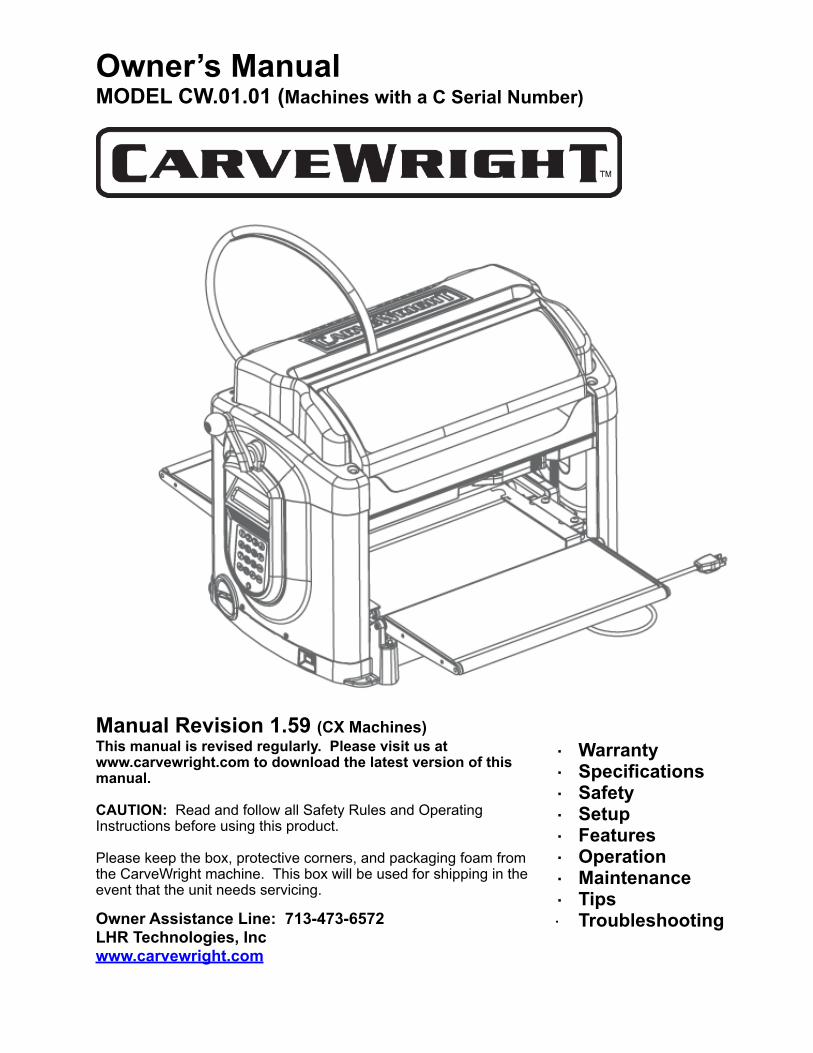
...................................................................................Package Size 28.5” Long x 20.25” Wide x 18” Deep
....................................................................................................................Package Weight 8 lbs (35.4 kg)
..................................................................................................................Machine Weight 70 lbs (31.8 kg)
......................................................................................................Cut Motor Speed (No Load) 20,000 rpm
............................................................................................................Cut Motor Horsepower (Peak) 1.0Hp
........................................................................................................Electrical Rating 110VAC at 8 A, 60 HZ
............................................................................................................................Power Cord Length 6 feet
......................................................................................Maximum Cut Depth 1” (or length of cutting flutes)
Movement Velocity:..................................................................................................................Length Axis 2 inches per second
..................................................................................................................Width Axis 12 inches per second
.............................................................................................................Up/down Axis 12 inches per second
Workpiece Size (Min):............................................................................................................................Length 7.0 inches
..............................................................................................................................Width 1.5 inches
............................................................................................................................Height .0.5 inches
Workpiece Size (Max):............................................................................................Length 144 inches (Limited by weight)
............................................................................................................................Width 14.5 inches
.............................................................................................................................Height 5.0 inches
LHR Technologies, Inc. CarveWright™ System (Rev 1.59) 08/18/17 6
Rules for Safe Operation
CAUTION: Read and follow all Safety Rules and all Operating Instructions before using this product.
General Safety Rules For Power Tools
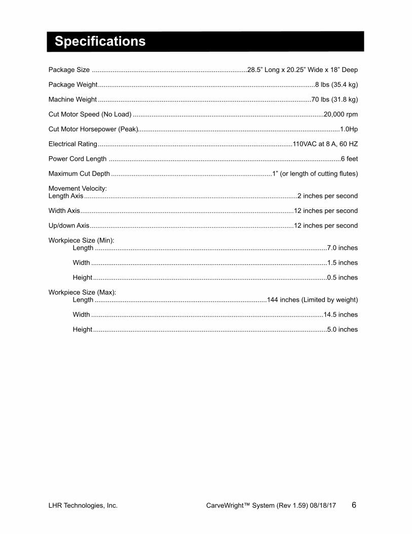
ALWAYS WEAR EYE PROTECTION. The operation of any power tool can result in foreign objects being thrown into the eyes, which can result in severe injury. Before beginning tool operation, always wear safety goggles or safety glasses with side shields and a full-face shield when needed. A Wide Vision Safety Mask is recommended for use over eyeglasses or standard safety glasses with side shields. Always wear eye protection that is marked to comply with ANSI Z87.1.
ALWAYS WEAR EAR PROTECTION. Power tools can generate high levels of noise that will cause permanent hearing loss. Before beginning tool operation, always don hearing protection to minimize the risk of damaging hearing.
ALWAYS BE ALERT. Operating electrically powered machinery poses a risk of serious physical injury to hands and fingers. Always operate machinery with ALL guards in place and in good working order. DO NOT attempt to defeat safety guards!
• KNOW THE POWER TOOL. Read the operator's manual carefully. Learn the machine’s applications and limitations as well as any specific potential hazards related to this tool.
• MAINTAIN TOOLS WITH CARE. Keep cutting tools sharp and clean for better and safer performance. Follow instructions for lubricating and changing accessories.
• USE THE RIGHT TOOL FOR THE JOB. Do not force the tool or attachment to do a job for which it was not designed. Use it only the way it was intended.
• DO NOT OVERREACH. Keep proper footing and balance at all times.• KEEP WORK AREA CLEAN. Cluttered work areas and workbenches invite accidents. Keep floors
clean and free of accumulated dust. DO NOT leave tools or pieces of wood on top of the machine or on support extensions while it is in operation.
• KEEP WORK AREA WELL LIGHTED. Good lighting promotes safety and good output.• DO NOT USE IN DANGEROUS ENVIRONMENT. Do not use power tools near gasoline or other
flammable liquids or explosive fumes. Do not use in damp or wet conditions. • WEAR A DUST MASK to keep from inhaling fine particles. Use wood dust collection systems
whenever possible.• NEVER LEAVE A RUNNING TOOL UNATTENDED. Turn the power off and do not leave the tool until
it comes to a complete stop.• USE THE PROPER EXTENSION CORD. Make sure the extension cord is in good condition. Use only
a cord heavy enough to carry the current the product will draw (see under Electrical Connections the proper gauges and lengths to use.)
• DISCONNECT TOOL from the outlet when not in use or before servicing.
LHR Technologies, Inc. CarveWright™ System (Rev 1.59) 08/18/17 7
• DRESS PROPERLY. Do not wear loose clothing, gloves, neckties, rings, bracelets, or other jewelry near a running machine. They can get caught and draw the user into moving parts. Wear protective hair covering to contain long hair. Non-slip footwear is recommended.
• GUARD AGAINST ELECTRICAL SHOCK by preventing body contact with grounded surfaces such as pipes, radiators, or appliances while using the tool.
• GROUND ALL TOOLS. When using an external dust collection system or vacuum make sure to use only grounded equipment to reduce the risk that harmful static electricity will accumulate due to the air flow. (Also See Electrical Connections)
• DO NOT ABUSE POWER CORD. Never yank the cord to disconnect it from receptacle. Keep the cord from heat, oil, and sharp edges. Inspect power cords regularly and repair or replace if damaged.
• PROTECT VISITORS AND CHILDREN. All visitors should wear safety glasses, hearing protection, and be kept a safe distance from work area. Do not let visitors contact the tool or extension cord while it is operating.
• MAKE WORKSHOP CHILDPROOF. Use padlocks and master switches, and remove switch keys • AVOID ACCIDENTAL STARTING. Be sure switch is off when plugging in the tool.• DO NOT OPERATE ANY POWER TOOL WHILE UNDER THE INFLUENCE OF DRUGS, ALCOHOL,
OR ANY MEDICATION AFFECTING ALERTNESS.• STAY ALERT AND EXERCISE CONTROL. Stay alert and use common sense. Do not operate the tool
when tired. Do not rush.
Specific Safety Rules & Precautions For The CarveWright.WARNING: Look for this symbol throughout this manual. It points out important safety precautions. It means attention -- Personal safety is involved!
• WHILE USING MACHINE, make sure that the power to the machine is kept constant. Using other high power draw machines on the same power leg may cause the machine to lose position and damage the workpiece.
• BEFORE MAKING A CUT, be sure that all mechanical adjustments and settings are secure. Until thoroughly familiar with the operation, it is a good idea to create a checklist to help ensure all are secure.
• REMOVE WRENCHES AND ADJUSTING KEYS. Get in the habit of checking - before turning on the tool - that any hex keys or adjusting wrenches are removed from tool.
• CHECK FOR DAMAGE. Before using the tool, routinely check for any damaged parts, including guards. Look for anything that could interfere with proper operation and performance, such as any binding or misalignment of moving parts or any sign of instability in the carving system. A damaged part must be properly repaired or replaced by a qualified service technician at a repair center to avoid risk of personal injury.
• BE SURE THE BIT CLEARS THE WORKPIECE. Never start the system with the bit touching the work piece.
• DO NOT HOLD OR STRESS THE FLEX SHAFT DURING OPERATION. Placing stress on the shaft during operation will accelerate wear and cause premature failure.
• NEVER ATTEMPT TO DEFEAT SAFETY DEVICES OR INTERLOCKS. Guards and other safety devices protect the user from injury; do not try to bypass or remove them.
• KEEP HANDS AWAY FROM CUTTING AREA. When the machine is running, never reach underneath the workpiece or into the blade-cutting path for any reason.
• DO NOT PLACE HANDS ON THE GRIT SURFACE DRIVE BELTS DURING OPERATION. Belts in motion could drag a hand into the machine and cause injury.
• AVOID AWKWARD OPERATIONS AND HAND POSITIONS where a sudden slip could cause hands to move into the cutting area.
• NEVER OPERATE THE MACHINE WITHOUT THE MUFFLER BAG IN PLACE. The bag captures dust and debris from machining operations.
• NEVER LOOK INTO THE VACUUM OUTLET DURING MACHINE OPERATION. Machining debris could be thrown out at high speed and cause eye injury.
• TURN OFF THE SYSTEM IF A STRANGE NOISE OR HEAVY VIBRATION OCCURS. Immediately turn off the system. Then locate and correct the source of the problem before restarting.
• USE A SUPPORT FOR LONG WORKPIECES. To minimize the risk of over stressing the machine, use a sturdy “outrigger” support when carving a long workpiece more than 36 inches in length. Never substitute a person for a proper support.
• USE RECOMMENDED ACCESSORIES. Using improper accessories may risk injury. Consult the accessories section for recommended accessories.
LHR Technologies, Inc. CarveWright™ System (Rev 1.59) 08/18/17 8
• USE ONLY APPROVED CUTTING BITS to ensure quality and to avoid equipment damage or injury.• KEEP BITS CLEAN AND SHARP. Sharp bits minimize workpiece burning, poor cut quality, and stress
to the system. Keep bits free of rust, grease, and pitch.• USE GLOVES TO HANDLE HOT CUTTING BITS. Recently used cutting bits are hot, and all bits have
sharp edges; gloves will help prevent cuts and burns.• USE ONLY ORIGINAL REPLACEMENT PARTS. Repairs using other than original replacement parts
may create a hazard as well as damage to the machine. To ensure proper repair using original replacement parts, a qualified service technician at a CarveWright service center should make all repairs, whether electrical or mechanical.
• DO NOT USE THE TOOL IF THE POWER SWITCH DOES NOT TURN IT ON AND OFF. Have defective switches replaced by a CarveWright service center.
• CUT ONLY WOOD, PLASTIC OR WOOD-LIKE MATERIALS. Do not cut metal.• NEVER cut more than one piece at a time. • DO NOT STACK more than one workpiece in the CarveWright at a time.• BE SURE THE WORKPIECE PATH IS FREE OF NAILS. Inspect for, and remove all nails, staples,
and protruding features from the lumber before cutting.• KEEP TOOL DRY, CLEAN, AND FREE FROM OIL AND GREASE. Always use a clean cloth when
cleaning. Never use brake fluids, gasoline, petroleum-based products, or any solvents to clean the system.
• DO NOT STAND ON TOOL. Serious injury can occur if tool is tipped or if the cutting tool is unintentionally contacted.
WARNING: Operation of this tool should not be attempted until all instructions, safety rules, etc. contained in this manual have been read thoroughly and understood completely. Failure to do so can result in accidents involving fire, electric shock, or serious personal injury. Save the operator's manual and review it frequently for continuing safe operation and for instructing others who may use this tool.
WARNING! Some dust created by power sanding, cutting, and drilling contains chemicals known to cause cancer, birth defects, allergic reactions, or reproductive damage. Some examples of these chemicals are: Lead from lead-based paints, Arsenic, copper, and chromium from chemically treated lumber, Wood resin, Plastic solvents, and Silica Dust.
To reduce exposure to these chemicals: 1) Work in a well ventilated area, 2) Work with approved safety equipment, such as dust masks that are specially designed to filter out microscopic particles AND 3) Keep the machine and work area clean.
IMPORTANT NOTE: Servicing requires much care and specialized knowledge of the system and should be performed only by a qualified service technician. For service, return the machine to the nearest repair center in the original packaging.
LHR Technologies, Inc. CarveWright™ System (Rev 1.59) 08/18/17 9
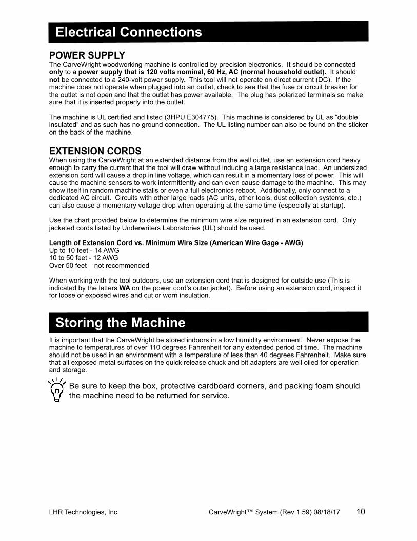
Electrical ConnectionsPOWER SUPPLYThe CarveWright woodworking machine is controlled by precision electronics. It should be connected only to a power supply that is 120 volts nominal, 60 Hz, AC (normal household outlet). It should not be connected to a 240-volt power supply. This tool will not operate on direct current (DC). If the machine does not operate when plugged into an outlet, check to see that the fuse or circuit breaker for the outlet is not open and that the outlet has power available. The plug has polarized terminals so make sure that it is inserted properly into the outlet.
The machine is UL certified and listed (3HPU E304775). This machine is considered by UL as “double insulated” and as such has no ground connection. The UL listing number can also be found on the sticker on the back of the machine.
EXTENSION CORDSWhen using the CarveWright at an extended distance from the wall outlet, use an extension cord heavy enough to carry the current that the tool will draw without inducing a large resistance load. An undersized extension cord will cause a drop in line voltage, which can result in a momentary loss of power. This will cause the machine sensors to work intermittently and can even cause damage to the machine. This may show itself in random machine stalls or even a full electronics reboot. Additionally, only connect to a dedicated AC circuit. Circuits with other large loads (AC units, other tools, dust collection systems, etc.) can also cause a momentary voltage drop when operating at the same time (especially at startup).
Use the chart provided below to determine the minimum wire size required in an extension cord. Only jacketed cords listed by Underwriters Laboratories (UL) should be used.
Length of Extension Cord vs. Minimum Wire Size (American Wire Gage - AWG)Up to 10 feet - 14 AWG10 to 50 feet - 12 AWGOver 50 feet – not recommended
When working with the tool outdoors, use an extension cord that is designed for outside use (This is indicated by the letters WA on the power cord's outer jacket). Before using an extension cord, inspect it for loose or exposed wires and cut or worn insulation.
Storing the MachineIt is important that the CarveWright be stored indoors in a low humidity environment. Never expose the machine to temperatures of over 110 degrees Fahrenheit for any extended period of time. The machine should not be used in an environment with a temperature of less than 40 degrees Fahrenheit. Make sure that all exposed metal surfaces on the quick release chuck and bit adapters are well oiled for operation and storage.
Be sure to keep the box, protective cardboard corners, and packing foam should the machine need to be returned for service.
LHR Technologies, Inc. CarveWright™ System (Rev 1.59) 08/18/17 10
GlossaryBevel Cut - A cut made across a workpiece that results in an angle other than 90˚ to the table surface.Cross Cut - A cutting operation across the grain or width of the workpiece.Head Screw - The threaded shaft on each side of the machine by which the head is raised and lowered when activated by the head crank.Joint or Jointing - A trim cut parallel to the grain of the wood on the edges of a board to create 90-degree angle with the top and bottom surface. A joint will create a smooth and, most important, straight edge and is often used in preparation for a glue joint to attach the board to another piece of wood.LCD - Liquid Crystal Display – The two-line text display found above the keypad.Miter Cut - A vertical cut made at any angle other than 0˚ across the workpiece.Molding - A shaping cut that gives a varied profile to the workpiece.Pitch - A sticky, sap-based substance found in some woods.Raster Carving - A carving produced by taking many small passes with the carving bit, building the image one line at a time. Rip Cut - A cut made parallel to the grain or length of the workpiece.Rout - To hollow, scoop or carve out.Snipe - An unwanted depression formed near the end of a workpiece caused by the uneven transition of the workpiece from one support surface to another. Minimize snipe by ensuring that the auxiliary outfeed supports are properly adjusted. The free end of the workpiece should also be well supported so that its weight does not place lifting pressure at the end of the workpiece being carved.Squaring Cut - A smoothing trim cut across the grain of the wood on the end of a board to create 90-degree angles with the top, bottom, and side edges.Vector Cut - A cutting operation that is composed of a group of strokes from one point to another. These can be lines, circles, splines or any other number of geometric elements.Workpiece - Is the item on which the cutting operation is being performed. The surfaces of a workpiece are commonly referred to as faces, ends, and edges.
LHR Technologies, Inc. CarveWright™ System (Rev 1.59) 08/18/17 11
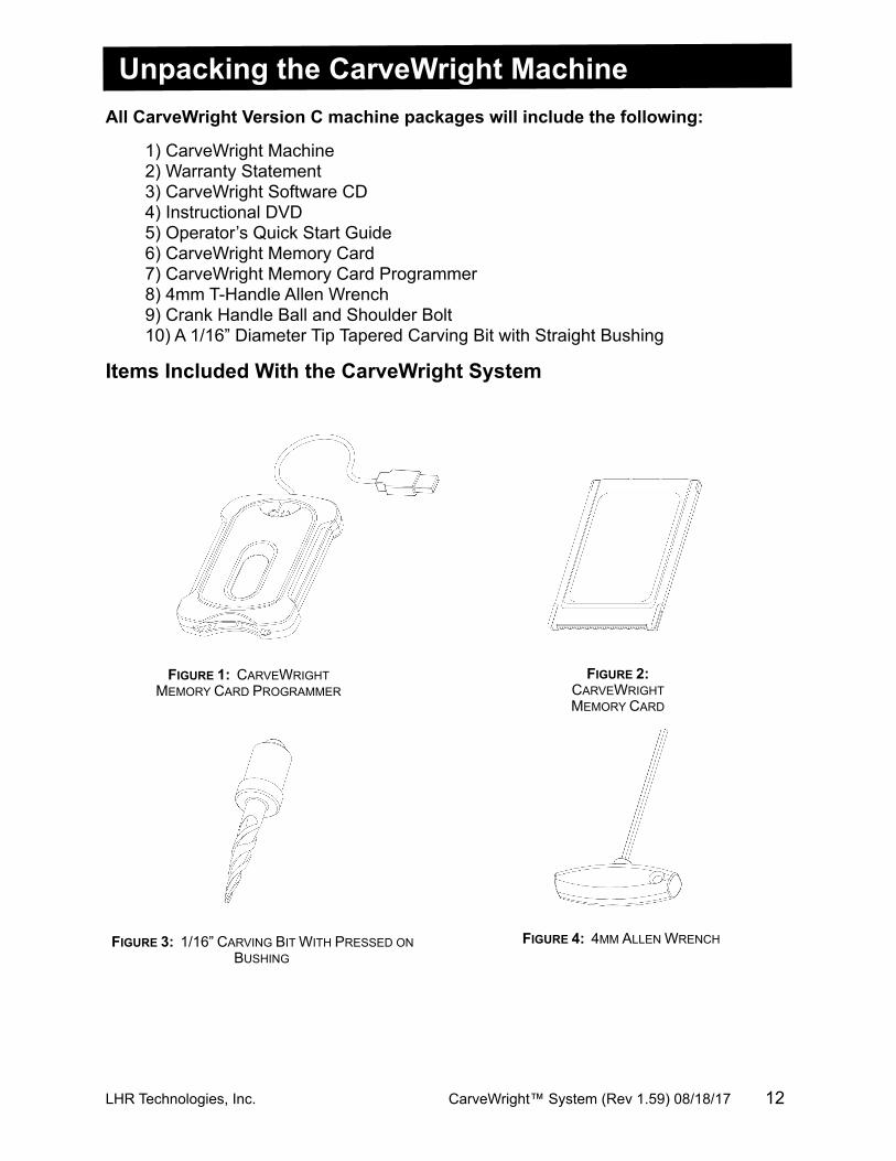
Unpacking the CarveWright MachineAll CarveWright Version C machine packages will include the following:
1) CarveWright Machine2) Warranty Statement3) CarveWright Software CD4) Instructional DVD5) Operator’s Quick Start Guide6) CarveWright Memory Card7) CarveWright Memory Card Programmer8) 4mm T-Handle Allen Wrench9) Crank Handle Ball and Shoulder Bolt10) A 1/16” Diameter Tip Tapered Carving Bit with Straight Bushing
Items Included With the CarveWright System
LHR Technologies, Inc. CarveWright™ System (Rev 1.59) 08/18/17 12
FIGURE 2: CARVEWRIGHT MEMORY CARD
FIGURE 1: CARVEWRIGHT MEMORY CARD PROGRAMMER
FIGURE 3: 1/16” CARVING BIT WITH PRESSED ON BUSHING
FIGURE 4: 4MM ALLEN WRENCH
Unpacking and Setting Up the CarveWright System1. Remove the top packaging foam: After opening the shipping box, carefully
remove the top molded foam packing from the machine. Located in the top tray are items B through K listed above.
2. Remove the machine from box: With a helper, lift out the machine and place it on a sturdy table or bench. Fold down the Outfeed Support Tables. Remove the plastic film covering the top clear safety cover.
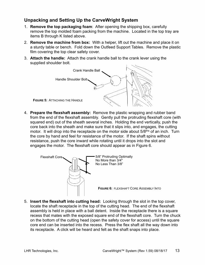
3. Attach the handle: Attach the crank handle ball to the crank lever using the supplied shoulder bolt.
4. Prepare the flexshaft assembly: Remove the plastic wrapping and rubber band from the end of the flexshaft assembly. Gently pull the protruding flexshaft core (with squared end) out of the sheath several inches. Holding the end vertically, push the core back into the sheath and make sure that it slips into, and engages, the cutting motor. It will drop into the receptacle on the motor side about 5/8ths of an inch. Turn the core by hand and feel for resistance of the motor. If the shaft spins without resistance, push the core inward while rotating until it drops into the slot and engages the motor. The flexshaft core should appear as in Figure 6.
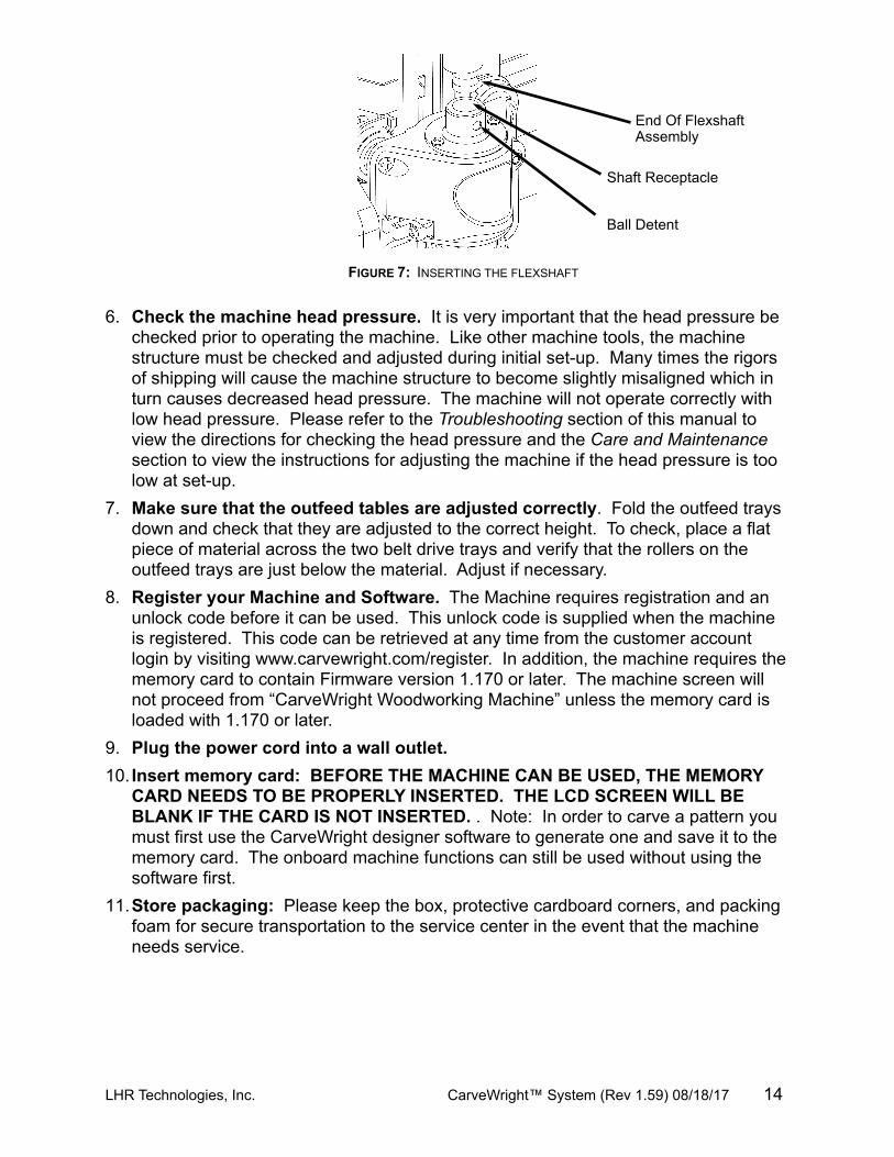
5. Insert the flexshaft into cutting head: Looking through the slot in the top cover, locate the shaft receptacle in the top of the cutting head. The end of the flexshaft assembly is held in place with a ball detent. Inside the receptacle there is a square recess that mates with the exposed square end of the flexshaft core. Turn the chuck on the bottom of the cutting head (open the safety cover for access) until the square core end can be inserted into the recess. Press the flex shaft all the way down into its receptacle. A click will be heard and felt as the shaft snaps into place.
LHR Technologies, Inc. CarveWright™ System (Rev 1.59) 08/18/17 13
FIGURE 5: ATTACHING THE HANDLE
FIGURE 6: FLEXSHAFT CORE ASSEMBLY INTO
Handle Shoulder Bolt
Crank Handle Ball
Flexshaft Core 5/8” Protruding OptimallyNo More than 3/4"No Less Than 3/8”
6. Check the machine head pressure. It is very important that the head pressure be checked prior to operating the machine. Like other machine tools, the machine structure must be checked and adjusted during initial set-up. Many times the rigors of shipping will cause the machine structure to become slightly misaligned which in turn causes decreased head pressure. The machine will not operate correctly with low head pressure. Please refer to the Troubleshooting section of this manual to view the directions for checking the head pressure and the Care and Maintenance section to view the instructions for adjusting the machine if the head pressure is too low at set-up.
7. Make sure that the outfeed tables are adjusted correctly. Fold the outfeed trays down and check that they are adjusted to the correct height. To check, place a flat piece of material across the two belt drive trays and verify that the rollers on the outfeed trays are just below the material. Adjust if necessary.
8. Register your Machine and Software. The Machine requires registration and an unlock code before it can be used. This unlock code is supplied when the machine is registered. This code can be retrieved at any time from the customer account login by visiting www.carvewright.com/register. In addition, the machine requires the memory card to contain Firmware version 1.170 or later. The machine screen will not proceed from “CarveWright Woodworking Machine” unless the memory card is loaded with 1.170 or later.
9. Plug the power cord into a wall outlet.10. Insert memory card: BEFORE THE MACHINE CAN BE USED, THE MEMORY
CARD NEEDS TO BE PROPERLY INSERTED. THE LCD SCREEN WILL BE BLANK IF THE CARD IS NOT INSERTED. . Note: In order to carve a pattern you must first use the CarveWright designer software to generate one and save it to the memory card. The onboard machine functions can still be used without using the software first.
11.Store packaging: Please keep the box, protective cardboard corners, and packing foam for secure transportation to the service center in the event that the machine needs service.
LHR Technologies, Inc. CarveWright™ System (Rev 1.59) 08/18/17 14
FIGURE 7: INSERTING THE FLEXSHAFT
Shaft Receptacle
End Of Flexshaft Assembly
Ball Detent
Flexshaft Assembly
Head Crank Handle
LCD Display
Keypad
Head Locking Lever (Shown in
Non-Locked Position)
Memory Card Slot
Vertical Corner Post
Power Switch
Folding Outfeed Table
Sliding Guide Plate Release Lever
Top Safety Cover
Cutting Trucks
Display Contrast Control
Outfeed Table Height Adjuster
Head
Sliding Guide Plate
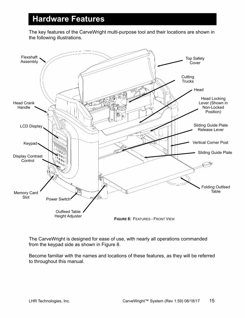
Hardware FeaturesThe key features of the CarveWright multi-purpose tool and their locations are shown in the following illustrations.
The CarveWright is designed for ease of use, with nearly all operations commanded from the keypad side as shown in Figure 8.
Become familiar with the names and locations of these features, as they will be referred to throughout this manual.
LHR Technologies, Inc. CarveWright™ System (Rev 1.59) 08/18/17 15
FIGURE 8: FEATURES - FRONT VIEW
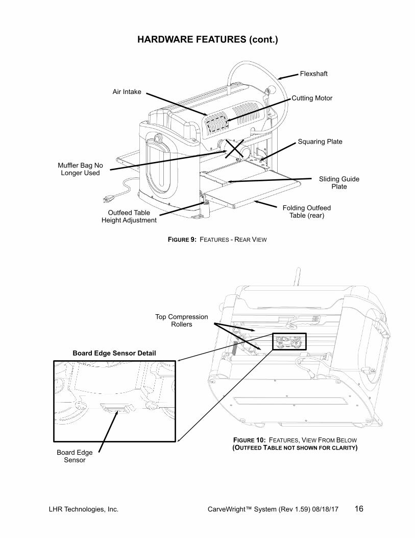
Board EdgeSensor
Top Compression Rollers
HARDWARE FEATURES (cont.)
LHR Technologies, Inc. CarveWright™ System (Rev 1.59) 08/18/17 16
FIGURE 9: FEATURES - REAR VIEW
Muffler Bag No Longer Used
Flexshaft
Folding Outfeed Table (rear)
Sliding Guide Plate
Outfeed Table Height Adjustment
Squaring Plate
Cutting MotorAir Intake
FIGURE 10: FEATURES, VIEW FROM BELOW (OUTFEED TABLE NOT SHOWN FOR CLARITY)
Board Edge Sensor Detail
HARDWARE FEATURES (cont.)
LHR Technologies, Inc. CarveWright™ System (Rev 1.59) 08/18/17 17
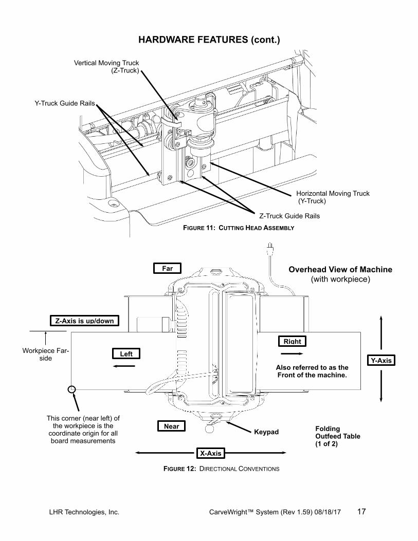
Y-Truck Guide Rails
Z-Truck Guide Rails
Vertical Moving Truck(Z-Truck)
Horizontal Moving Truck (Y-Truck)
FIGURE 12: DIRECTIONAL CONVENTIONS
Near
Far
X-Axis
Y-Axis
Right
Left
Z-Axis is up/down
Overhead View of Machine(with workpiece)
Keypad
This corner (near left) of the workpiece is the
coordinate origin for all board measurements
Workpiece Far-side
Also referred to as the Front of the machine.
FIGURE 11: CUTTING HEAD ASSEMBLY
Folding Outfeed Table (1 of 2)
OperationUsing the CarveWright System Before the CarveWright can begin to function, the CarveWright memory card must be installed. With the power off, push the memory card gently into the memory card slot until it stops, making sure the label is up.
WARNING: Never remove the memory card from the machine while it is on. Doing so can result in damage to the workpiece.At any point during operation the CarveWright machine can be stopped by pressing the STOP key or by lifting the cover. If desired the machine can be restarted by closing the cover and pressing ENTER. The machine will resume cutting at the point where it was stopped. Pressing the STOP button a second time will abort the project, so be careful when restarting.
Note for reading this manual: all keypad button selections will be shown in bold and all LCD menu displays will be shown in italics.
Once the CarveWright memory card is installed, the machine can be turned on with the power switch. Look at the LCD display, and rotate the contrast control knob (located directly under the keypad) until the display is readable from a comfortable angle.The CompuCarve may be used in two complementary ways. First, and most powerfully, the CompuCarve can carve intricate patterns and designs created through the CarveWright design software running on a computer. In order to carve a pattern you must first use the software to generate one and save it to the memory card. Second, there are built-in woodworking functions on-board the machine including:· Rip and Cross Cuts· Edge Jointing· End Squaring· Miter Cuts· Bevel Cuts· Edge RoutingThese built-in functions are generally used to prepare a board for carving, but they can be used to dress up a board if desired. (See section titled Built-In Functions below.)
Creating Projects with the CarveWright™ SoftwareDiscussion of the usage of the CarveWright design software is beyond the scope of this manual and is covered separately. Please refer to the CarveWright design software Help Menu along with the other resources available on the website (tutorials, forum, classes, etc.).
It is advisable to have a supply of suitably sized scrap wood on hand for trial cuts. Very often it is desirable to tweak details in a design before doing a final carving.
LHR Technologies, Inc. CarveWright™ System (Rev 1.59) 08/18/17 18
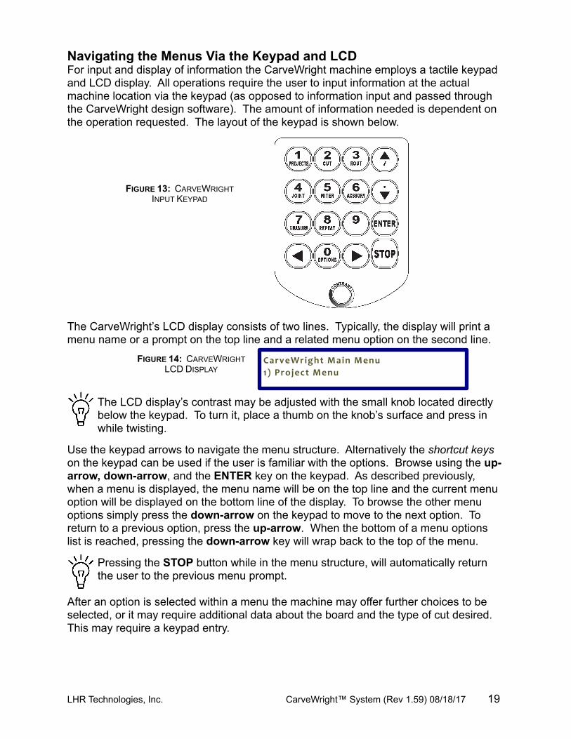
Navigating the Menus Via the Keypad and LCDFor input and display of information the CarveWright machine employs a tactile keypad and LCD display. All operations require the user to input information at the actual machine location via the keypad (as opposed to information input and passed through the CarveWright design software). The amount of information needed is dependent on the operation requested. The layout of the keypad is shown below.
The CarveWright’s LCD display consists of two lines. Typically, the display will print a menu name or a prompt on the top line and a related menu option on the second line.
The LCD display’s contrast may be adjusted with the small knob located directly below the keypad. To turn it, place a thumb on the knob’s surface and press in while twisting.
Use the keypad arrows to navigate the menu structure. Alternatively the shortcut keys on the keypad can be used if the user is familiar with the options. Browse using the up-arrow, down-arrow, and the ENTER key on the keypad. As described previously, when a menu is displayed, the menu name will be on the top line and the current menu option will be displayed on the bottom line of the display. To browse the other menu options simply press the down-arrow on the keypad to move to the next option. To return to a previous option, press the up-arrow. When the bottom of a menu options list is reached, pressing the down-arrow key will wrap back to the top of the menu.
Pressing the STOP button while in the menu structure, will automatically return the user to the previous menu prompt.
After an option is selected within a menu the machine may offer further choices to be selected, or it may require additional data about the board and the type of cut desired. This may require a keypad entry.
LHR Technologies, Inc. CarveWright™ System (Rev 1.59) 08/18/17 19
FIGURE 13: CARVEWRIGHT INPUT KEYPAD
FIGURE 14: CARVEWRIGHT LCD DISPLAY
CarveWright Main Menu1) Project Menu
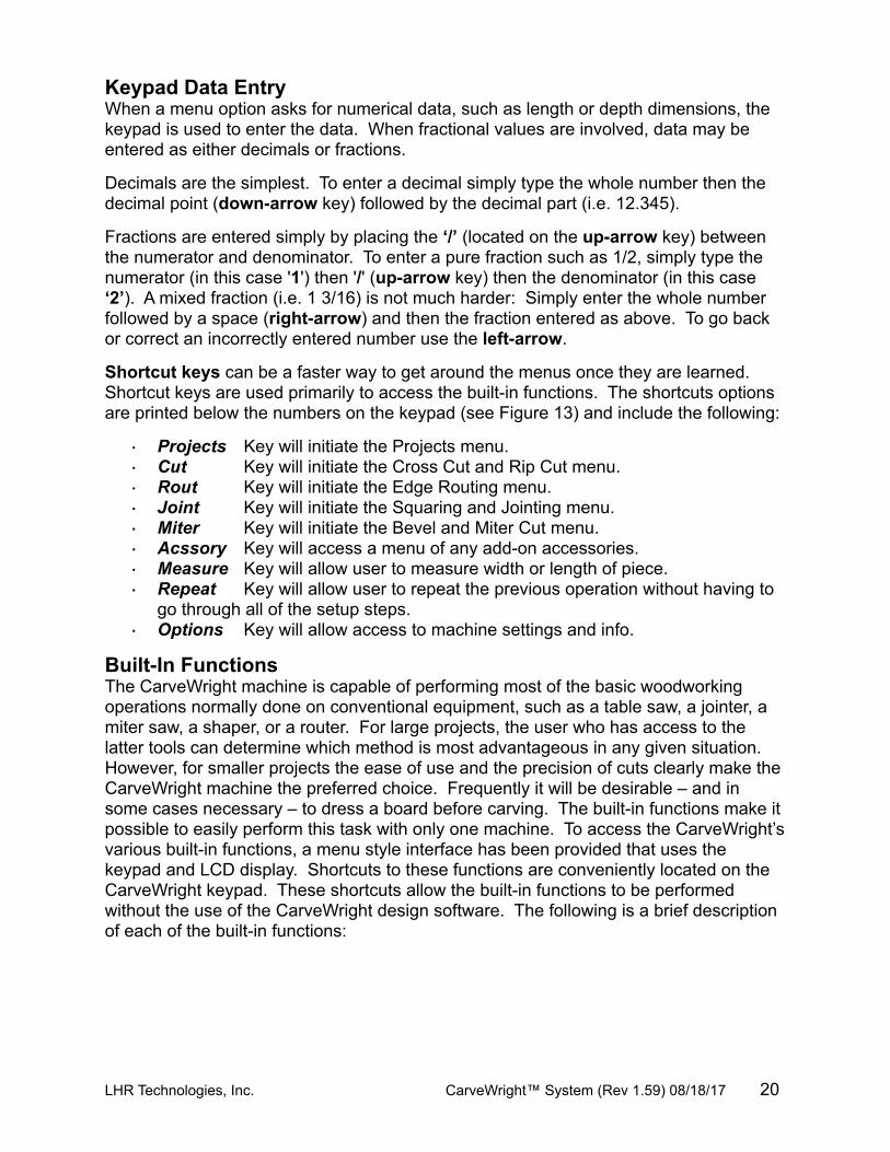
Keypad Data EntryWhen a menu option asks for numerical data, such as length or depth dimensions, the keypad is used to enter the data. When fractional values are involved, data may be entered as either decimals or fractions.
Decimals are the simplest. To enter a decimal simply type the whole number then the decimal point (down-arrow key) followed by the decimal part (i.e. 12.345).
Fractions are entered simply by placing the ‘/’ (located on the up-arrow key) between the numerator and denominator. To enter a pure fraction such as 1/2, simply type the numerator (in this case '1') then '/' (up-arrow key) then the denominator (in this case ‘2’). A mixed fraction (i.e. 1 3/16) is not much harder: Simply enter the whole number followed by a space (right-arrow) and then the fraction entered as above. To go back or correct an incorrectly entered number use the left-arrow.
Shortcut keys can be a faster way to get around the menus once they are learned. Shortcut keys are used primarily to access the built-in functions. The shortcuts options are printed below the numbers on the keypad (see Figure 13) and include the following:
· Projects Key will initiate the Projects menu.· Cut Key will initiate the Cross Cut and Rip Cut menu.· Rout Key will initiate the Edge Routing menu.· Joint Key will initiate the Squaring and Jointing menu.· Miter Key will initiate the Bevel and Miter Cut menu.· Acssory Key will access a menu of any add-on accessories.· Measure Key will allow user to measure width or length of piece.· Repeat Key will allow user to repeat the previous operation without having to
go through all of the setup steps.· Options Key will allow access to machine settings and info.
Built-In FunctionsThe CarveWright machine is capable of performing most of the basic woodworking operations normally done on conventional equipment, such as a table saw, a jointer, a miter saw, a shaper, or a router. For large projects, the user who has access to the latter tools can determine which method is most advantageous in any given situation. However, for smaller projects the ease of use and the precision of cuts clearly make the CarveWright machine the preferred choice. Frequently it will be desirable – and in some cases necessary – to dress a board before carving. The built-in functions make it possible to easily perform this task with only one machine. To access the CarveWright’s various built-in functions, a menu style interface has been provided that uses the keypad and LCD display. Shortcuts to these functions are conveniently located on the CarveWright keypad. These shortcuts allow the built-in functions to be performed without the use of the CarveWright design software. The following is a brief description of each of the built-in functions:
LHR Technologies, Inc. CarveWright™ System (Rev 1.59) 08/18/17 20
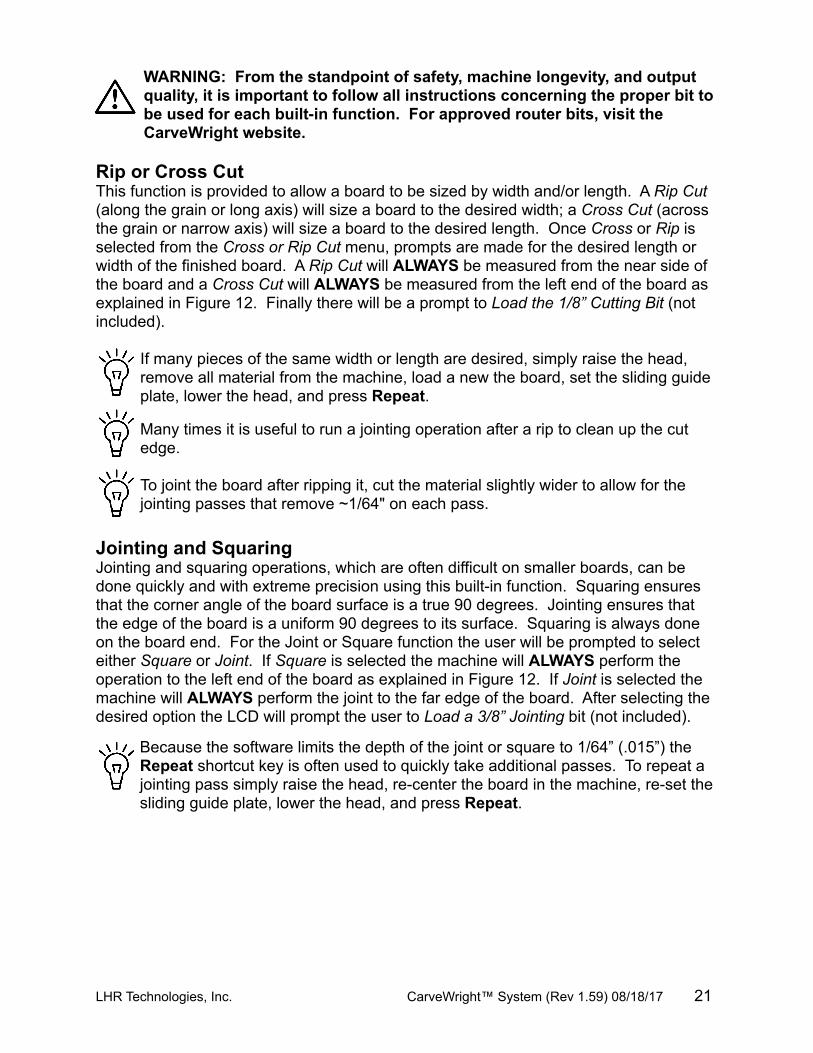
WARNING: From the standpoint of safety, machine longevity, and output quality, it is important to follow all instructions concerning the proper bit to be used for each built-in function. For approved router bits, visit the CarveWright website.
Rip or Cross CutThis function is provided to allow a board to be sized by width and/or length. A Rip Cut (along the grain or long axis) will size a board to the desired width; a Cross Cut (across the grain or narrow axis) will size a board to the desired length. Once Cross or Rip is selected from the Cross or Rip Cut menu, prompts are made for the desired length or width of the finished board. A Rip Cut will ALWAYS be measured from the near side of the board and a Cross Cut will ALWAYS be measured from the left end of the board as explained in Figure 12. Finally there will be a prompt to Load the 1/8” Cutting Bit (not included).
If many pieces of the same width or length are desired, simply raise the head, remove all material from the machine, load a new the board, set the sliding guide plate, lower the head, and press Repeat.
Many times it is useful to run a jointing operation after a rip to clean up the cut edge.
To joint the board after ripping it, cut the material slightly wider to allow for the jointing passes that remove ~1/64" on each pass.
Jointing and SquaringJointing and squaring operations, which are often difficult on smaller boards, can be done quickly and with extreme precision using this built-in function. Squaring ensures that the corner angle of the board surface is a true 90 degrees. Jointing ensures that the edge of the board is a uniform 90 degrees to its surface. Squaring is always done on the board end. For the Joint or Square function the user will be prompted to select either Square or Joint. If Square is selected the machine will ALWAYS perform the operation to the left end of the board as explained in Figure 12. If Joint is selected the machine will ALWAYS perform the joint to the far edge of the board. After selecting the desired option the LCD will prompt the user to Load a 3/8” Jointing bit (not included).
Because the software limits the depth of the joint or square to 1/64” (.015”) the Repeat shortcut key is often used to quickly take additional passes. To repeat a jointing pass simply raise the head, re-center the board in the machine, re-set the sliding guide plate, lower the head, and press Repeat.
LHR Technologies, Inc. CarveWright™ System (Rev 1.59) 08/18/17 21
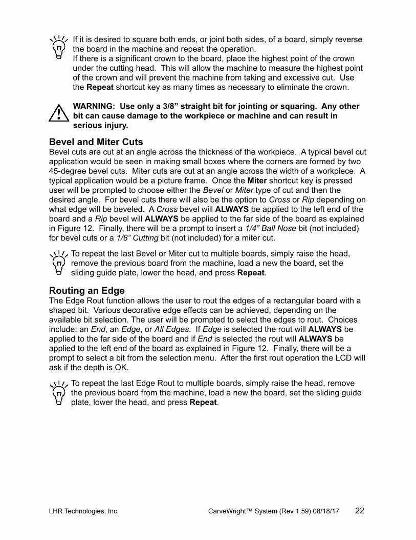
If it is desired to square both ends, or joint both sides, of a board, simply reverse the board in the machine and repeat the operation. If there is a significant crown to the board, place the highest point of the crown under the cutting head. This will allow the machine to measure the highest point of the crown and will prevent the machine from taking and excessive cut. Use the Repeat shortcut key as many times as necessary to eliminate the crown.
WARNING: Use only a 3/8” straight bit for jointing or squaring. Any other bit can cause damage to the workpiece or machine and can result in serious injury.
Bevel and Miter CutsBevel cuts are cut at an angle across the thickness of the workpiece. A typical bevel cut application would be seen in making small boxes where the corners are formed by two 45-degree bevel cuts. Miter cuts are cut at an angle across the width of a workpiece. A typical application would be a picture frame. Once the Miter shortcut key is pressed user will be prompted to choose either the Bevel or Miter type of cut and then the desired angle. For bevel cuts there will also be the option to Cross or Rip depending on what edge will be beveled. A Cross bevel will ALWAYS be applied to the left end of the board and a Rip bevel will ALWAYS be applied to the far side of the board as explained in Figure 12. Finally, there will be a prompt to insert a 1/4” Ball Nose bit (not included) for bevel cuts or a 1/8” Cutting bit (not included) for a miter cut.
To repeat the last Bevel or Miter cut to multiple boards, simply raise the head, remove the previous board from the machine, load a new the board, set the sliding guide plate, lower the head, and press Repeat.
Routing an EdgeThe Edge Rout function allows the user to rout the edges of a rectangular board with a shaped bit. Various decorative edge effects can be achieved, depending on the available bit selection. The user will be prompted to select the edges to rout. Choices include: an End, an Edge, or All Edges. If Edge is selected the rout will ALWAYS be applied to the far side of the board and if End is selected the rout will ALWAYS be applied to the left end of the board as explained in Figure 12. Finally, there will be a prompt to select a bit from the selection menu. After the first rout operation the LCD will ask if the depth is OK.
To repeat the last Edge Rout to multiple boards, simply raise the head, remove the previous board from the machine, load a new the board, set the sliding guide plate, lower the head, and press Repeat.
LHR Technologies, Inc. CarveWright™ System (Rev 1.59) 08/18/17 22
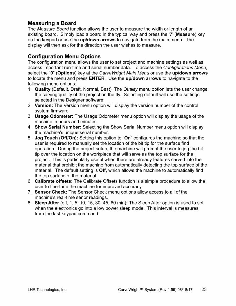
Measuring a BoardThe Measure Board function allows the user to measure the width or length of an existing board. Simply load a board in the typical way and press the ‘7’ (Measure) key on the keypad or use the up/down arrows to navigate from the main menu. The display will then ask for the direction the user wishes to measure.
Configuration Menu OptionsThe configuration menu allows the user to set project and machine settings as well as access important run-time and serial number data. To access the Configurations Menu, select the “0” (Options) key at the CarveWright Main Menu or use the up/down arrows to locate the menu and press ENTER. Use the up/down arrows to navigate to the following menu options:1. Quality (Default, Draft, Normal, Best): The Quality menu option lets the user change
the carving quality of the project on the fly. Selecting default will use the settings selected in the Designer software.
2. Version: The Version menu option will display the version number of the control system firmware.
3. Usage Odometer: The Usage Odometer menu option will display the usage of the machine in hours and minutes.
4. Show Serial Number: Selecting the Show Serial Number menu option will display the machine’s unique serial number.
5. Jog Touch (Off/On): Setting this option to “On” configures the machine so that the user is required to manually set the location of the bit tip for the surface find operation. During the project setup, the machine will prompt the user to jog the bit tip over the location on the workpiece that will serve as the top surface for the project. This is particularly useful when there are already features carved into the material that prohibit the machine from automatically detecting the top surface of the material. The default setting is Off, which allows the machine to automatically find the top surface of the material.
6. Calibrate offsets: The Calibrate Offsets function is a simple procedure to allow the user to fine-tune the machine for improved accuracy.
7. Sensor Check: The Sensor Check menu options allow access to all of the machine’s real-time senor readings.
8. Sleep After (off, 1, 5, 10, 15, 30, 45, 60 min): The Sleep After option is used to set when the electronics go into a low power sleep mode. This interval is measures from the last keypad command.
LHR Technologies, Inc. CarveWright™ System (Rev 1.59) 08/18/17 23
Carving a ProjectA project is a set of related design elements (patterns or figures) created with the CarveWright design software and stored on the memory card. These stored projects are accessed from the keypad. Simply press the ‘1’ (Projects) shortcut key to open the Projects Menu which can then be browsed using the up and down arrows. Once located, the desired project can be selected by pressing ENTER. Upon selection of a project from the project menu, the CarveWright will lead the user through the preparation process. The first instruction will be to insert a board.
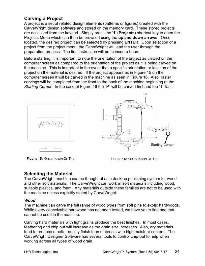
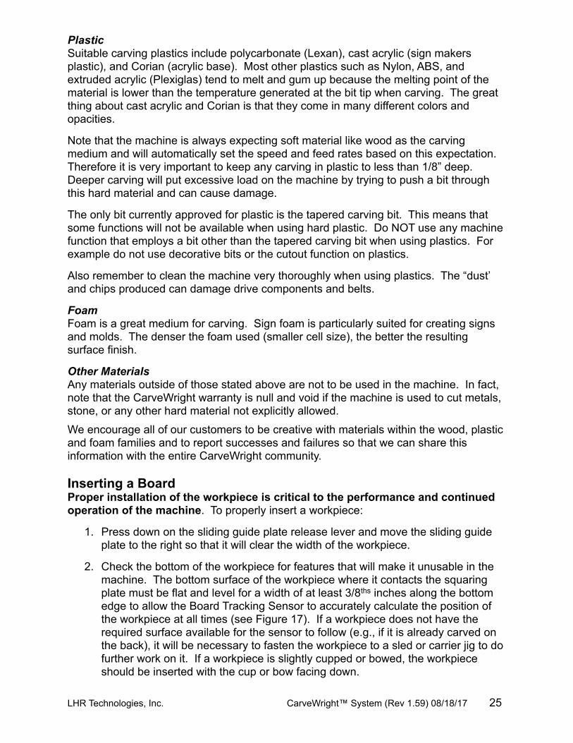
Before starting, it is important to note the orientation of the project as viewed on the computer screen as compared to the orientation of the project as it is being carved on the machine. This is important in the event that a specific orientation or location of the project on the material is desired. If the project appears as in Figure 15 on the computer screen it will be carved in the machine as seen in Figure 16. Also, raster carvings will be completed from the front to the back of the machine beginning at the Starting Corner. In the case of Figure 16 the “P” will be carved first and the “T” last.
Selecting the MaterialThe CarveWright machine can be thought of as a desktop publishing system for wood and other soft materials. The CarveWright can work in soft materials including wood, suitable plastics, and foam. Any materials outside these families are not to be used with the machine unless explicitly stated by CarveWright.
WoodThe machine can carve the full range of wood types from soft pine to exotic hardwoods. While every conceivable hardwood has not been tested, we have yet to find one that cannot be used in the machine.
Carving hard materials with tight grains produce the best finishes. In most cases, feathering and chip out will increase as the grain size increases. Also, dry materials tend to produce a better quality finish than materials with high moisture content. The CarveWright Designer Software has several tools to control chip-out to help when working across all types of wood grain.
LHR Technologies, Inc. CarveWright™ System (Rev 1.59) 08/18/17 24
FIGURE 16: ORIENTATION OF THE FIGURE 15: ORIENTATION OF THE
Starting Corner
PlasticSuitable carving plastics include polycarbonate (Lexan), cast acrylic (sign makers plastic), and Corian (acrylic base). Most other plastics such as Nylon, ABS, and extruded acrylic (Plexiglas) tend to melt and gum up because the melting point of the material is lower than the temperature generated at the bit tip when carving. The great thing about cast acrylic and Corian is that they come in many different colors and opacities.
Note that the machine is always expecting soft material like wood as the carving medium and will automatically set the speed and feed rates based on this expectation. Therefore it is very important to keep any carving in plastic to less than 1/8” deep. Deeper carving will put excessive load on the machine by trying to push a bit through this hard material and can cause damage.
The only bit currently approved for plastic is the tapered carving bit. This means that some functions will not be available when using hard plastic. Do NOT use any machine function that employs a bit other than the tapered carving bit when using plastics. For example do not use decorative bits or the cutout function on plastics.
Also remember to clean the machine very thoroughly when using plastics. The “dust’ and chips produced can damage drive components and belts.
FoamFoam is a great medium for carving. Sign foam is particularly suited for creating signs and molds. The denser the foam used (smaller cell size), the better the resulting surface finish.
Other MaterialsAny materials outside of those stated above are not to be used in the machine. In fact, note that the CarveWright warranty is null and void if the machine is used to cut metals, stone, or any other hard material not explicitly allowed.
We encourage all of our customers to be creative with materials within the wood, plastic and foam families and to report successes and failures so that we can share this information with the entire CarveWright community.
Inserting a BoardProper installation of the workpiece is critical to the performance and continued operation of the machine. To properly insert a workpiece:
1. Press down on the sliding guide plate release lever and move the sliding guide plate to the right so that it will clear the width of the workpiece.
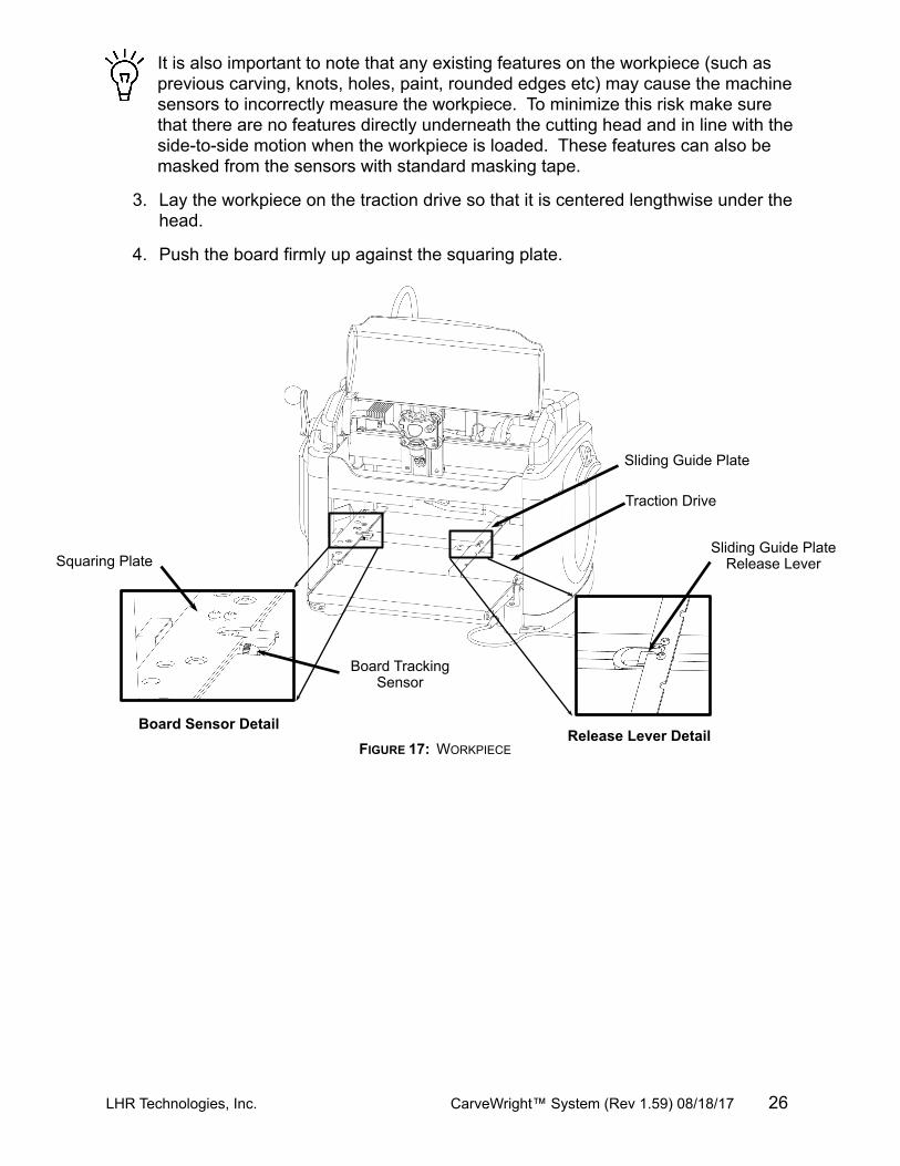
2. Check the bottom of the workpiece for features that will make it unusable in the machine. The bottom surface of the workpiece where it contacts the squaring plate must be flat and level for a width of at least 3/8ths inches along the bottom edge to allow the Board Tracking Sensor to accurately calculate the position of the workpiece at all times (see Figure 17). If a workpiece does not have the required surface available for the sensor to follow (e.g., if it is already carved on the back), it will be necessary to fasten the workpiece to a sled or carrier jig to do further work on it. If a workpiece is slightly cupped or bowed, the workpiece should be inserted with the cup or bow facing down.
LHR Technologies, Inc. CarveWright™ System (Rev 1.59) 08/18/17 25
It is also important to note that any existing features on the workpiece (such as previous carving, knots, holes, paint, rounded edges etc) may cause the machine sensors to incorrectly measure the workpiece. To minimize this risk make sure that there are no features directly underneath the cutting head and in line with the side-to-side motion when the workpiece is loaded. These features can also be masked from the sensors with standard masking tape.
3. Lay the workpiece on the traction drive so that it is centered lengthwise under the head.
4. Push the board firmly up against the squaring plate.
LHR Technologies, Inc. CarveWright™ System (Rev 1.59) 08/18/17 26
FIGURE 17: WORKPIECE
Board Sensor DetailRelease Lever Detail
Board Tracking Sensor
Traction Drive
Sliding Guide Plate
Squaring Plate Sliding Guide Plate
Release Lever
Locking LeverIn Locked Position
(Out Position)
5. Gently push the sliding plate up against the inside edge of the workpiece. DO NOT push the sliding plate against the workpiece with significant force. The sliding plate is used to guide the workpiece and is not intended to lock the piece in position.
6. At this point it is critical to assure that the workpiece can travel freely in and out of the machine along its entire length without binding or encountering significant drag. Do this by moving the workpiece in and out of the machine by hand while it is lying flat on the traction drive.WARNING: Do not attempt to load a workpiece that has a significant taper to the sides. A tapered workpiece will bind between the sliding plate and the squaring plate and will damage the traction drive.WARNING: Do not attempt to load a workpiece that varies in thickness by more than 1/16” along its entire length. Using a workpiece with a larger thickness variation than 1/16” can lead to damage to the machine.
7. Next, lower the head by turning the head crank handle counter-clockwise. Once the correct pressure loading of the head is reached the clutch will begin to ratchet (causing a clicking sound). It is recommended that the crank be rotated at least two full revolutions once the clicking sound is heard to assure full loading.The clutch is intended to load the board against the traction drive with consistent force. In certain cases the machine can sense if the workpiece is not loaded enough and repeatably display Please Load Board on the LCD. Most often this decreased loading is caused by insufficient lubrication of the four vertical corner posts or the two vertical leadscrews. Please see the Checking the Head Pressure in the troubleshooting section for the proper lubrication procedure.
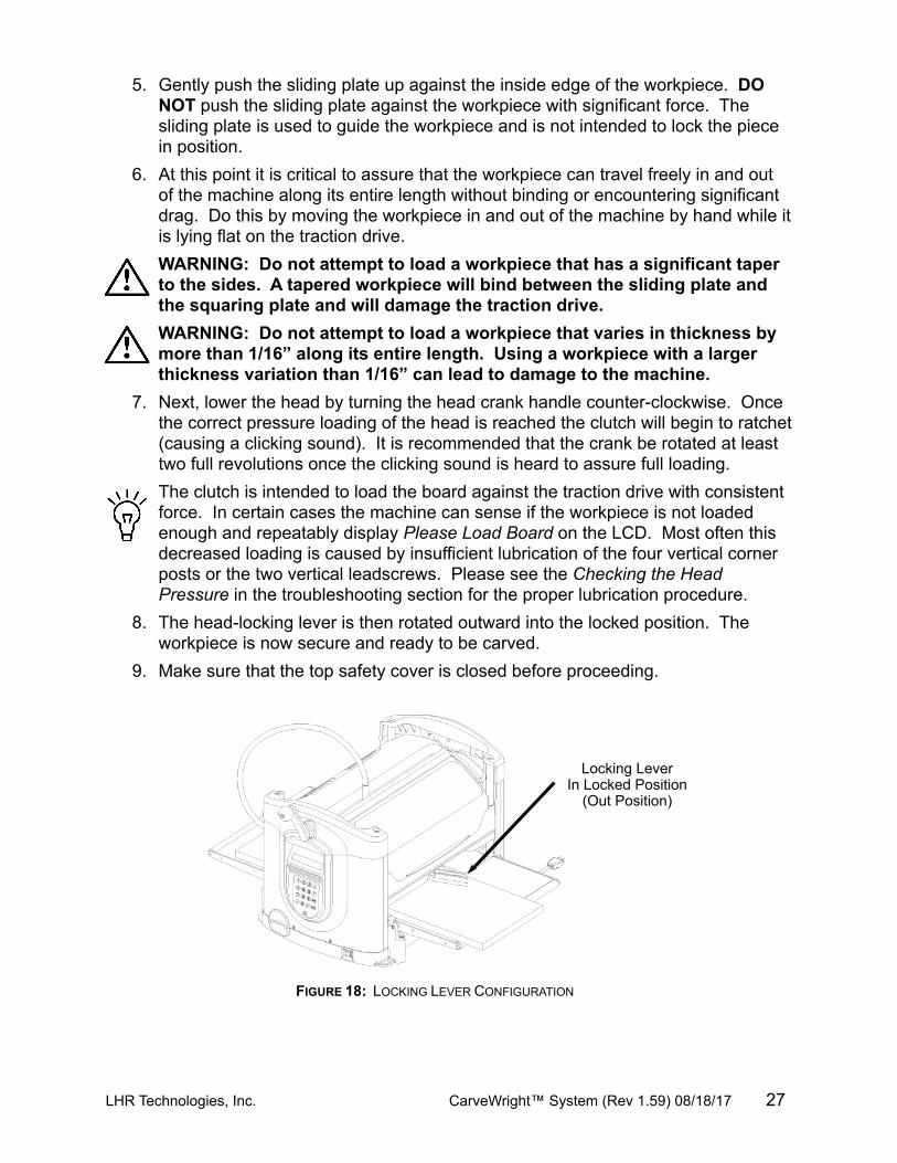
8. The head-locking lever is then rotated outward into the locked position. The workpiece is now secure and ready to be carved.
9. Make sure that the top safety cover is closed before proceeding.
LHR Technologies, Inc. CarveWright™ System (Rev 1.59) 08/18/17 27
FIGURE 18: LOCKING LEVER CONFIGURATION
Make sure that the locking lever is released (pushed in) after finishing carving. If the locking lever is NOT released the head will not be able to move up and down.
WARNING: Failure to correctly load the workpiece by ratcheting the clutch at least at least two full revolutions after the clicking begins may result in diminished carving quality.
As a matter of regular maintenance, check that the Y and Z Cutting Trucks (Figure 11) are tight and do not have any play in them. Simply grab each one by hand and wiggle back and forth. If either of these trucks is loose they will need to be tightened. Failure to tighten these trucks will result in decreased carving quality. Please call the service help line for tightening instructions.
Workpiece PreparationBefore carving can begin a number of menu prompts and machine operations must be navigated. First, the machine will ask if the workpiece is to Stay Under Rollers.
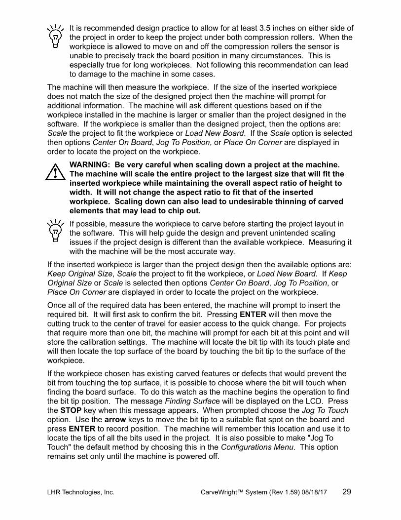
If YES to Stay Under Rollers is selected the machine will automatically assure that there is 3-1/2" extra length on either side of the project. In most cases a longer piece of material will have to be inserted to account for this extra length. The other option is to have the project scaled to the board size while accounting for the length needed to keep under rollers. Most times this will not produce the desired effect.
Keeping the workpiece under the top rollers is a way of avoiding undesirable snipe in the cut and maintaining contact with the Board Tracking Sensor at all times. It is highly recommended that this option be used whenever possible but especially under the following circumstances:
· When best carving quality is desired.
· When the project includes vector carving.
· When the project has routing to or near the ends of the board.
· When the project has cutting to or near the ends of the board.
· When the project is longer than 20 inches and there is carving to the ends of the board.
LHR Technologies, Inc. CarveWright™ System (Rev 1.59) 08/18/17 28
FIGURE 19: GRAPHIC DESCRIPTION OF STAY UNDER ROLLER OPTION (AREAS A&B ADDED)
Workpiece size as shown in the design
software
Workpiece size as shown in the design
softwareA B
It is recommended design practice to allow for at least 3.5 inches on either side of the project in order to keep the project under both compression rollers. When the workpiece is allowed to move on and off the compression rollers the sensor is unable to precisely track the board position in many circumstances. This is especially true for long workpieces. Not following this recommendation can lead to damage to the machine in some cases.
The machine will then measure the workpiece. If the size of the inserted workpiece does not match the size of the designed project then the machine will prompt for additional information. The machine will ask different questions based on if the workpiece installed in the machine is larger or smaller than the project designed in the software. If the workpiece is smaller than the designed project, then the options are: Scale the project to fit the workpiece or Load New Board. If the Scale option is selected then options Center On Board, Jog To Position, or Place On Corner are displayed in order to locate the project on the workpiece.
WARNING: Be very careful when scaling down a project at the machine. The machine will scale the entire project to the largest size that will fit the inserted workpiece while maintaining the overall aspect ratio of height to width. It will not change the aspect ratio to fit that of the inserted workpiece. Scaling down can also lead to undesirable thinning of carved elements that may lead to chip out. If possible, measure the workpiece to carve before starting the project layout in the software. This will help guide the design and prevent unintended scaling issues if the project design is different than the available workpiece. Measuring it with the machine will be the most accurate way.
If the inserted workpiece is larger than the project design then the available options are: Keep Original Size, Scale the project to fit the workpiece, or Load New Board. If Keep Original Size or Scale is selected then options Center On Board, Jog To Position, or Place On Corner are displayed in order to locate the project on the workpiece.
Once all of the required data has been entered, the machine will prompt to insert the required bit. It will first ask to confirm the bit. Pressing ENTER will then move the cutting truck to the center of travel for easier access to the quick change. For projects that require more than one bit, the machine will prompt for each bit at this point and will store the calibration settings. The machine will locate the bit tip with its touch plate and will then locate the top surface of the board by touching the bit tip to the surface of the workpiece.
If the workpiece chosen has existing carved features or defects that would prevent the bit from touching the top surface, it is possible to choose where the bit will touch when finding the board surface. To do this watch as the machine begins the operation to find the bit tip position. The message Finding Surface will be displayed on the LCD. Press the STOP key when this message appears. When prompted choose the Jog To Touch option. Use the arrow keys to move the bit tip to a suitable flat spot on the board and press ENTER to record position. The machine will remember this location and use it to locate the tips of all the bits used in the project. It is also possible to make "Jog To Touch" the default method by choosing this in the Configurations Menu. This option remains set only until the machine is powered off.
LHR Technologies, Inc. CarveWright™ System (Rev 1.59) 08/18/17 29
The machine will then proceed to carve the project. A real time carving completion estimator will be displayed on the LCD and provides an estimate of how much of the current carving is completed. This completion estimator gives a completion estimate for the element that is carving at the time and does provide and estimate for the entire project. A time estimate for the entire project can be obtained in the design software when the project is uploaded to the memory card.
When the carving is completed, lift the top safety cover, release the head lockdown lever, and crank the head up to free the workpiece. The workpiece can then be removed and examined.
After removal from the machine, it is advisable to brush any “whiskers” from the carving with a small brass utility brush, and to blow it free of dust with compressed air.
Jogging the Cutting TruckAs described above, the machine offers several options for positioning the carving on the workpiece, one of which is “Jog to Position.” This is accomplished using the up and down arrows on the keypad to move the cutting truck across the width of the workpiece (near-to-far), and the left and right arrows will move the workpiece along its length (left or right).
This option allows the user to place a carving at some location on a workpiece other than center or left-front corner of the material. This is especially useful if one wishes to avoid a blemish in the wood or to incorporate some feature like a knot into the carving. Jog the tip of the bit to the location of the Starting Corner as seen in Figure 16.
Also it is important to note that the machine knows the size of the material loaded and the size of the project being carved. It will not jog to a starting corner that will position any part of the carving outside the boundary of the loaded material.
Holding an arrow key down results in a fast movement. Precise final positioning is accomplished using short bumps on the key.
In addition to jogging to position with the arrow keys, if any number key is pressed while in jog mode, the machine will enter coordinate mode. In coordinate mode, there will be a prompt for the X and Y coordinate destination. The machine coordinates will be the distances from the near-left hand corner of the workpiece (when facing the keypad).
Auto Jigging FunctionOccasionally a project will contain carvings or routs that can interfere with the mechanical operation of the machine. Types of interference fall into the following categories:
1. Wide vertical cuts across the top surface if the workpiece can cause the compression rollers to fall during a project, affecting the machine's ability to move the workpiece.
2. Cuts through the board along the top edge of the workpiece (as viewed in the software) can interfere with the Board Tracking Sensor and affect the machine's ability to track the position of the workpiece.
LHR Technologies, Inc. CarveWright™ System (Rev 1.59) 08/18/17 30
3. Carvings on the rear face of the workpiece and near the bottom of the workpiece (as viewed in the software) can also interfere with the Board Tracking Sensor when the workpiece is flipped over.
4. Cuts with the Cut Tool along the right side of the workpiece can potentially break the cutting bit if the workpiece leaves the Board Tracking Sensor and the machine loses high-precision tracking of the workpiece.
In the event that the CarveWright designer software recognizes that any of these conditions are met within a project, the software will display a warning when the project is uploaded to the memory card. The specific conditions will be listed, and the user may choose to ignore the warning (which may result in undesired machine operation), manually jig the project, or allow the machine to automatically jig the project (Auto-Jig).When Auto-Jig is selected, the machine will prompt for a workpiece that is slightly wider or longer than the project's dimensions in order to prevent interference with the machine's mechanics. When the project is complete the machine can cut off the extra material if desired.
WARNING: Whenever using the 1/8” cutting bit, it is strongly recommended that the Stay Under Rollers option be set to Yes. It is likely that the 1/8” cutting bit will be broken during operations near either end of the workpiece or undesirable stair stepping can occur.
Workpiece Size LimitationsSmall Workpiece - The minimum acceptable size of a workpiece that can be inserted into the CarveWright is 1.5 inches wide x 0.5 inches thick x 7 inches long. It will be necessary to mount the workpiece onto a jig if any single dimension is smaller than the stated minimums.Large Workpiece - The maximum size of a workpiece is limited only by the physical size of the CarveWright machine, and is 14.5 inches wide x 5 inches high x12 feet long. A workpiece over 3 feet long will require that additional stand-alone outfeed support rollers be used. The support rollers should be adjusted properly to avoid letting the workpiece sag or rise, as any transition going on and off the rollers will be reflected in the carved surface in a manner similar to a snipe.
The weight of the workpiece is also a limiting factor, related to both quality of the carving and longevity of the drive mechanism. Any workpiece more than 20 lbs in weight places increased stress on the drive mechanism and will accelerate wear of the system.
LHR Technologies, Inc. CarveWright™ System (Rev 1.59) 08/18/17 31
Spindle Shaft
4mm Allen Wrench
Grab Paw with Screw
Carving Bit in Straight Bushing
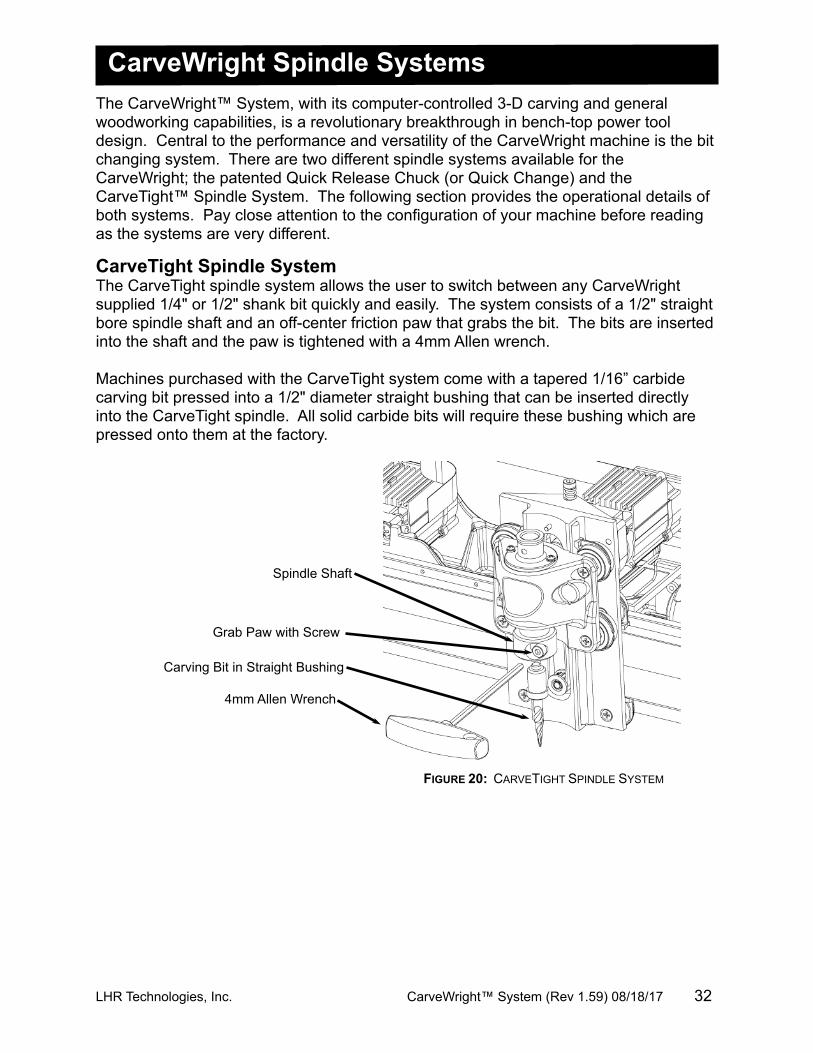
CarveWright Spindle SystemsThe CarveWright™ System, with its computer-controlled 3-D carving and general woodworking capabilities, is a revolutionary breakthrough in bench-top power tool design. Central to the performance and versatility of the CarveWright machine is the bit changing system. There are two different spindle systems available for the CarveWright; the patented Quick Release Chuck (or Quick Change) and the CarveTight™ Spindle System. The following section provides the operational details of both systems. Pay close attention to the configuration of your machine before reading as the systems are very different.
CarveTight Spindle SystemThe CarveTight spindle system allows the user to switch between any CarveWright supplied 1/4" or 1/2" shank bit quickly and easily. The system consists of a 1/2" straight bore spindle shaft and an off-center friction paw that grabs the bit. The bits are inserted into the shaft and the paw is tightened with a 4mm Allen wrench.
Machines purchased with the CarveTight system come with a tapered 1/16” carbide carving bit pressed into a 1/2" diameter straight bushing that can be inserted directly into the CarveTight spindle. All solid carbide bits will require these bushing which are pressed onto them at the factory.
LHR Technologies, Inc. CarveWright™ System (Rev 1.59) 08/18/17 32
FIGURE 20: CARVETIGHT SPINDLE SYSTEM
1/2" Stop Collar
1/4" Stop Collar
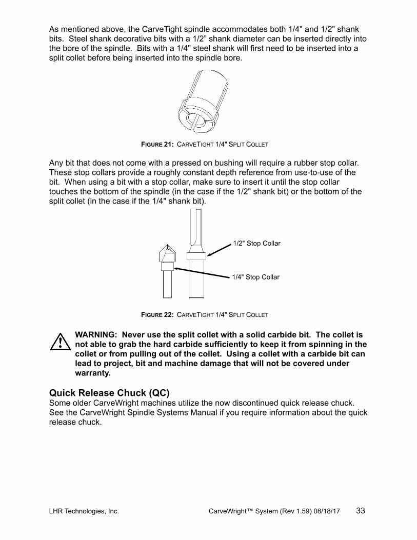
As mentioned above, the CarveTight spindle accommodates both 1/4" and 1/2" shank bits. Steel shank decorative bits with a 1/2” shank diameter can be inserted directly into the bore of the spindle. Bits with a 1/4" steel shank will first need to be inserted into a split collet before being inserted into the spindle bore.
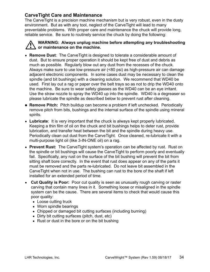
Any bit that does not come with a pressed on bushing will require a rubber stop collar. These stop collars provide a roughly constant depth reference from use-to-use of the bit. When using a bit with a stop collar, make sure to insert it until the stop collar touches the bottom of the spindle (in the case if the 1/2" shank bit) or the bottom of the split collet (in the case if the 1/4" shank bit).
WARNING: Never use the split collet with a solid carbide bit. The collet is not able to grab the hard carbide sufficiently to keep it from spinning in the collet or from pulling out of the collet. Using a collet with a carbide bit can lead to project, bit and machine damage that will not be covered under warranty.
Quick Release Chuck (QC)Some older CarveWright machines utilize the now discontinued quick release chuck. See the CarveWright Spindle Systems Manual if you require information about the quick release chuck.
LHR Technologies, Inc. CarveWright™ System (Rev 1.59) 08/18/17 33
FIGURE 21: CARVETIGHT 1/4" SPLIT COLLET
FIGURE 22: CARVETIGHT 1/4" SPLIT COLLET
CarveTight Care and MaintenanceThe CarveTight is a precision machine mechanism but is very robust, even in the dusty environment. But as with any tool, neglect of the CarveTight will lead to many preventable problems. With proper care and maintenance the chuck will provide long, reliable service. Be sure to routinely service the chuck by doing the following:
WARNING: Always unplug machine before attempting any troubleshooting or maintenance on the machine.
• Remove Dust: The CarveTight is designed to tolerate a considerable amount of dust. But to ensure proper operation it should be kept free of dust and debris as much as possible. Regularly blow out any dust from the recesses of the chuck. Always make sure to use low-pressure air (<80 psi) as high-pressure air can damage adjacent electronic components. In some cases dust may be necessary to clean the spindle (and bit bushings) with a cleaning solution. We recommend that WD40 be used. First lay out a rag or paper over the belt trays so as not to drip the WD40 onto the machine. Be sure to wear safety glasses as the WD40 can be an eye irritant. Use the straw nozzle to spray the WD40 up into the spindle. WD40 is a degreaser so please lubricate the spindle as described below to prevent rust after cleaning.
• Remove Pitch: Pitch buildup can become a problem if left unchecked. Periodically remove pitch from bits, bushings and the internal surface of the spindle using mineral spirits.
• Lubricate: It is very important that the chuck is always kept properly lubricated. Keeping a thin film of oil on the chuck and bit bushings helps to deter rust, provide lubrication, and transfer heat between the bit and the spindle during heavy use. Periodically clean out dust from the CarveTight. Once cleaned, re-lubricate it with a multi-purpose light oil (like 3-IN-ONE oil) on a rag.
• Prevent Rust: The CarveTight system’s operation can be affected by rust. Rust on the spindle or bit bushings will cause the CarveTight to perform poorly and eventually fail. Specifically, any rust on the surface of the bit bushing will prevent the bit from sitting shaft bore correctly. In the event that rust does appear on any of the parts it must be removed and the parts re-lubricated. Do not leave bit assembled in the CarveTight when not in use. The bushing can rust to the bore of the shaft if left installed for an extended period of time.
• Cut Quality is Poor: Poor cut quality is seen as unusually rough carving or raster carving that contain many lines in it. Something loose or misaligned in the spindle system can be the cause. There are several items to check that would cause this poor quality:• Loose cutting truck• Worn spindle bearings• Chipped or damaged bit cutting surfaces (including burning)• Dirty bit cutting surfaces (pitch, dust, etc)• Rust or dust in the bore or on the bit bushing
LHR Technologies, Inc. CarveWright™ System (Rev 1.59) 08/18/17 34
Cutting BitsThe CarveWright comes equipped with 1/16” tip diameter carving bit mounted in a 1/2" straight bushing. Additional bits and bit adapters, made to the CarveWright specifications, are available through the CarveWright web site.
WARNING: Piloted bits can NOT be used in the machine machine even if the pilot bearings have been removed.
WARNING: Use only CarveWright branded bits with the machine. The machine is calibrated to work with bits within certain specifications, and if these specifications are not met the results can be undesirable. It is possible to overstress the machine with nonstandard bits, which could be both damaging to the machine and hazardous.
WARNING: NEVER CUT DEEPER THAN THE LENGTH OF THE SHARPENED CUTTING SURFACE OF YOUR BIT. The maximum cut depth as stated in this Manual is 1" for the straight 1/8" cutting bit. The maximum carving depth for the 1/16" tapered carving bit is 3/4" because that is the length of the sharpened flutes. This max depth rule applies to all bits; you cannot carve deeper than the length of the sharpened cutting surface. If you program the project to go deeper than 3/4" with the carving bit you will most likely damage your machine or bits since the stress on the machine increases exponentially when the bit is not cutting. When doing cutouts make sure that you load the specified bit and always keep the project under rollers. Loading a 1/16” cutting bit into the machine when it is expecting a 1/8” bit will result in a broken bit.
LHR Technologies, Inc. CarveWright™ System (Rev 1.59) 08/18/17 35
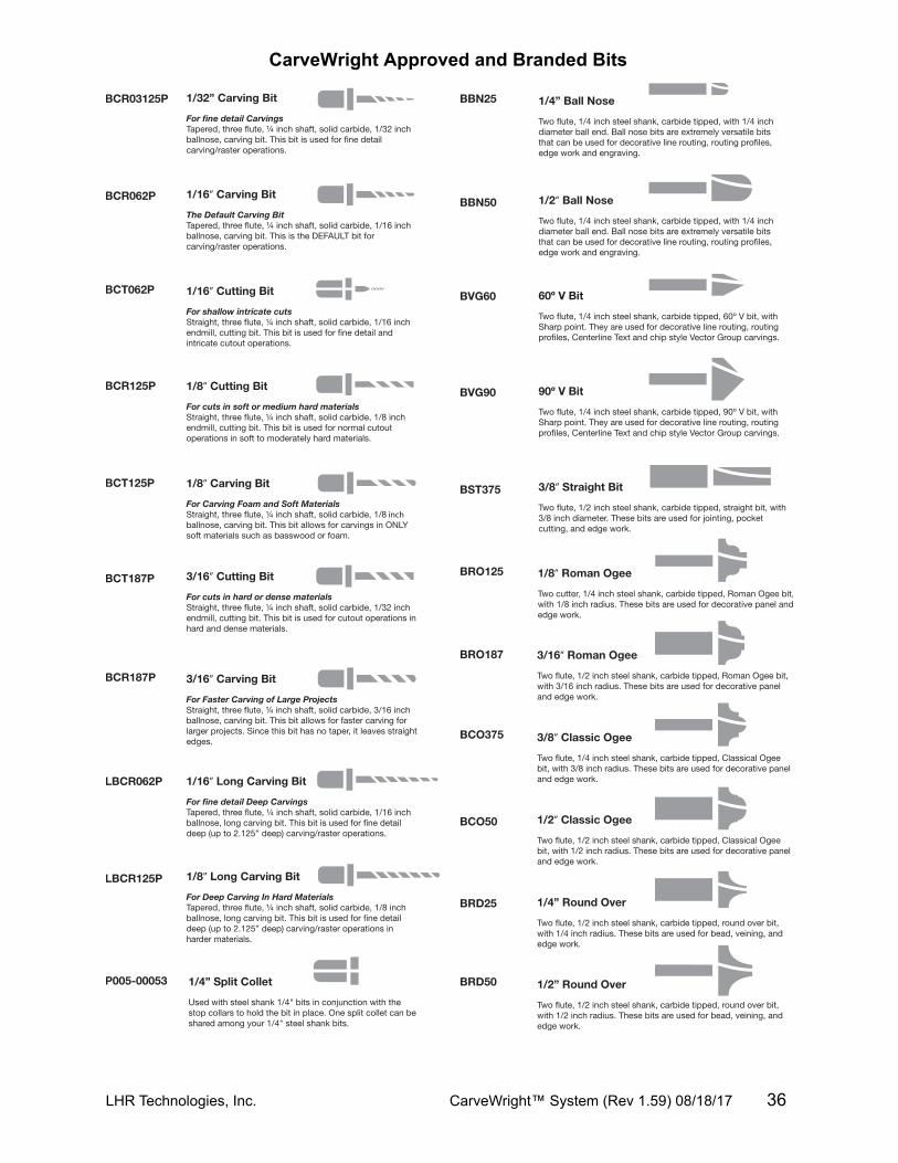
LHR Technologies, Inc. CarveWright™ System (Rev 1.59) 08/18/17 36
Care and MaintenanceThe CarveWright is a precision machine tool. With proper care and maintenance it will provide long, reliable service.
WARNING: Always unplug machine before attempting any troubleshooting or maintenance on the machine.
• Dust Removal: The CarveWright is designed to tolerate a considerable amount of carving system dust, but to ensure proper operation it should be kept free of debris as much as possible. Periodically blow or vacuum out any dust or debris from the recesses of the unit. Always make sure to use low-pressure air (<80 psi) around the electronics and sensors. High-pressure air can damage components and actually push dust into them. The machine can be adapted to external dust removal systems. Be sure that these vacuum systems are properly grounded because of the large static charge that they tend to generate. The warranty does not cover electronics failures due to Electrostatic Discharge (ESD).
•
• Check the Head Pressure: It is very important that the head pressure is checked regularly in order to maintain optimum machine performance. Specifically, the sandpaper drive belts are prone to roll-up on the ends if the head loading drops below 60 lbs as determined by our scale test. The head loading can change over time due to dust absorbing the grease off the four corner posts and lead screws. This detailed check and lubrication procedure can be found in the Troubleshooting section of this manual.
•
• Check the Cutting Trucks for Looseness. As a matter of regular maintenance, check that the Y and Z Cutting Trucks (Figure 13) are tight and do not have any play in them. Simply grab each one by hand and wiggle back and forth. If either of these trucks is loose they will need to be tightened. Failure to tighten these trucks will result in decreased carving quality. Please call the service help line for tightening instructions.
•
• Check Sandpaper Belts for Tears or Roll-up. Visually inspect the two sandpaper belts each time the machine is used. Look for tears or roll-up of the end of the belt. Roll up will always occur on the control panel side of the machine. The ends of the belts will roll under themselves and form a doubled over raised portion on the belt end.
•• Pitch Removal: Pitch buildup is not a big problem, but should a workpiece with a
high content of pitch be carved there may be some pitch deposits on the cutter bit and elsewhere. This is easily removed using mineral spirits.
•
• The Muffler and Dust Collector Bag should be removed and cleaned out periodically to ensure a good airflow.
•
• The Flexshaft temperature should never rise to the point where the sheath cannot be held by hand for an extended period of time. If the sheath ever becomes hot to the touch, immediately stop the machine and consult the Lubrication section below. If the heating persists after lubrication please contact CarveWright Technical support.
•
• Lubrication: Several areas of the CarveWright machine will require occasional cleaning and re-lubrication.
LHR Technologies, Inc. CarveWright™ System (Rev 1.59) 08/18/17 37
o The flexshaft core should be cleaned and re-lubricated only if it begins to exhibit heating during operation. To access the core, first unplug the CarveWright machine from power. Firmly grasp the flexshaft outer sheath where it is snapped into the machine’s cutting head and pull it free from the head. The core is contained within the sheath, and should slide out freely when grasped between finger and thumb. Inspect the core for debris and clean with a lint free cloth if necessary. The recommended lubricant is a commercially available chain lube with Moly. Spray the lubricant onto the core and let sit for an hour. After applying the specified lubricant slide the core back into its sheath. When near full insertion, the core may need to be carefully rotated with the fingers to ensure that its square end engages correctly with the cutting motor. Once the core is fully inserted in the sheath, it can once again be snapped into the cutting head. Rotate the bit chuck if necessary to get the square end to engage with the chuck.
o The guide rods/rails upon which the cutting head assembly rides need to be kept free of cutting debris. They should be wiped or blown off before carving a project, and wiped occasionally with a thin coat of light oil for lubrication. If the rails are allowed to accumulate dust and debris, the machine will halt during usage and an error message will be seen on the display with a reminder to clean the rails. Once they have been cleaned, pressing the ENTER key on the keypad will resume operation.
o The vertical guide rods at the corners of the machine also need to be clean and rust free for smooth operation. A thin coat of marine grease applied to the rods will help keep them free of rust.
• Replacement Items: Occasionally, due to wear or accident, some components of the machine will need replacement:o The flexshaft will periodically need to be replaced. The time period will depend on
the duration and type of use the machine has had.o Belt replacement: The toothed belts used for various motion functions are
expected to last the life of the machine. If they are damaged, they will require replacement at a CarveWright service center.
o Traction belt replacement: The grit-faced traction used to grip the workpiece and move it through the machine may need to be replaced from time to time. Replacement belts can be purchased at a CarveWright service center.
• Accessories and Parts Source: Available accessories, approved cutting bits, and user-replaceable parts can be obtained through the CarveWright website.
LHR Technologies, Inc. CarveWright™ System (Rev 1.59) 08/18/17 38
Initial Set-Up and Alignment
Adjusting the Head PressureChecking the head pressure and adjusting the vertical guide rods is part of the machine set-up process. The head pressure should also be checked periodically during routine maintenance. There are several reasons that the head pressure may be low.
• Insufficient lubrication on the vertical guide rods or leadscrews.• Misalignment in the vertical guide rods.• Poor mesh on the gears that drive the vertical leadscrews.
Please refer to the Troubleshooting section of the Operators Manual for the procedure for checking the head pressure and lubricating the vertical guide rods. The proper head loading should be between 75 and 85 pounds.
If lubricating the vertical guide rods does not resolve the low head pressure reading, then realigning them is needed. The vertical guide rods are located at the four corners of the machine and are the rails upon which the head of the machine rides up and down. If these vertical guide rods are shifted out of alignment the head may bind when lowered, and the pressure put on the workpiece by the head may be too low for optimum operation. These vertical guide rods can be knocked out of alignment during shipping or when the machine is moved.
In order to adjust the vertical guide rods you will need a #2 Phillips screwdriver (or power drill with #2 screw bit) and a 10mm socket, socket wrench, and 3” extension.
1. Ready the machine. Unplug the machine from the power outlet and place it on a stable work platform. Raise the head up several inches for best access. Move the Z-truck to the very top of its travel (until it reaches the hard stop) so that the flexshaft support tube protrudes from the head cover.
2. Detach the flexshaft from the top of the Z-truck: The flexshaft assembly is retained by a ball detent located in the flexshaft receptacle (See Figure 24). Firmly grasp the flexshaft support tube while reaching under the clear front cover with your other hand to grab the Z-truck. Pull up firmly on the flexshaft support tube and twist slightly while bracing the Z-truck. DO NOT PULL ON THE SHEATH. The flexshaft will pop out of the detent. Wrap the end of the flexshaft in tape so that the core will not fall out and lay the detached flexshaft end to the side.
LHR Technologies, Inc. CarveWright™ System (Rev 1.59) 08/18/17 39
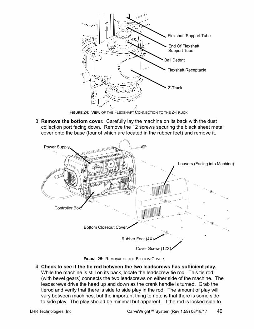
3. Remove the bottom cover. Carefully lay the machine on its back with the dust collection port facing down. Remove the 12 screws securing the black sheet metal cover onto the base (four of which are located in the rubber feet) and remove it.
4. Check to see if the tie rod between the two leadscrews has sufficient play. While the machine is still on its back, locate the leadscrew tie rod. This tie rod (with bevel gears) connects the two leadscrews on either side of the machine. The leadscrews drive the head up and down as the crank handle is turned. Grab the tierod and verify that there is side to side play in the rod. The amount of play will vary between machines, but the important thing to note is that there is some side to side play. The play should be minimal but apparent. If the rod is locked side to
LHR Technologies, Inc. CarveWright™ System (Rev 1.59) 08/18/17 40
FIGURE 24: VIEW OF THE FLEXSHAFT CONNECTION TO THE Z-TRUCK
FIGURE 25: REMOVAL OF THE BOTTOM COVER
Bottom Closeout Cover
Cover Screw (12X)
Rubber Foot (4X)
Louvers (Facing into Machine)
Controller Box
Power Supply
Flexshaft Support Tube
Flexshaft Receptacle
End Of Flexshaft Support Tube
Ball Detent
Z-Truck
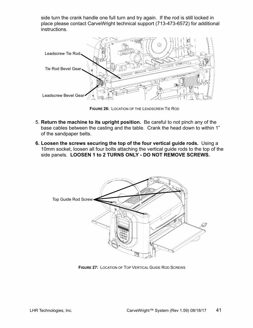
side turn the crank handle one full turn and try again. If the rod is still locked in place please contact CarveWright technical support (713-473-6572) for additional instructions.
5. Return the machine to its upright position. Be careful to not pinch any of the base cables between the casting and the table. Crank the head down to within 1” of the sandpaper belts.
6. Loosen the screws securing the top of the four vertical guide rods. Using a 10mm socket, loosen all four bolts attaching the vertical guide rods to the top of the side panels. LOOSEN 1 to 2 TURNS ONLY - DO NOT REMOVE SCREWS.
LHR Technologies, Inc. CarveWright™ System (Rev 1.59) 08/18/17 41
FIGURE 26: LOCATION OF THE LEADSCREW TIE ROD
FIGURE 27: LOCATION OF TOP VERTICAL GUIDE ROD SCREWS
Leadscrew Tie Rod
Tie Rod Bevel Gear
Leadscrew Bevel Gear
Top Guide Rod Screw
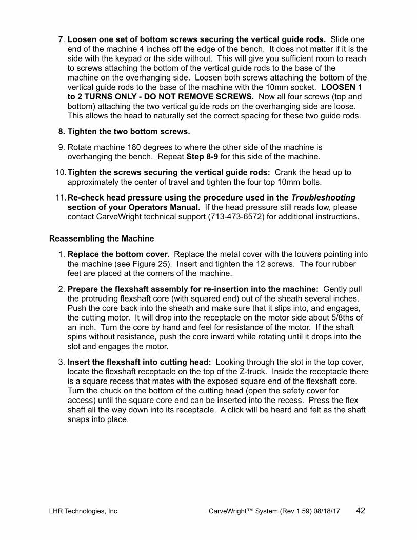
7. Loosen one set of bottom screws securing the vertical guide rods. Slide one end of the machine 4 inches off the edge of the bench. It does not matter if it is the side with the keypad or the side without. This will give you sufficient room to reach to screws attaching the bottom of the vertical guide rods to the base of the machine on the overhanging side. Loosen both screws attaching the bottom of the vertical guide rods to the base of the machine with the 10mm socket. LOOSEN 1 to 2 TURNS ONLY - DO NOT REMOVE SCREWS. Now all four screws (top and bottom) attaching the two vertical guide rods on the overhanging side are loose. This allows the head to naturally set the correct spacing for these two guide rods.
8. Tighten the two bottom screws.
9. Rotate machine 180 degrees to where the other side of the machine is overhanging the bench. Repeat Step 8-9 for this side of the machine.
10.Tighten the screws securing the vertical guide rods: Crank the head up to approximately the center of travel and tighten the four top 10mm bolts.
11.Re-check head pressure using the procedure used in the Troubleshooting section of your Operators Manual. If the head pressure still reads low, please contact CarveWright technical support (713-473-6572) for additional instructions.
Reassembling the Machine
1. Replace the bottom cover. Replace the metal cover with the louvers pointing into the machine (see Figure 25). Insert and tighten the 12 screws. The four rubber feet are placed at the corners of the machine.
2. Prepare the flexshaft assembly for re-insertion into the machine: Gently pull the protruding flexshaft core (with squared end) out of the sheath several inches. Push the core back into the sheath and make sure that it slips into, and engages, the cutting motor. It will drop into the receptacle on the motor side about 5/8ths of an inch. Turn the core by hand and feel for resistance of the motor. If the shaft spins without resistance, push the core inward while rotating until it drops into the slot and engages the motor.
3. Insert the flexshaft into cutting head: Looking through the slot in the top cover, locate the flexshaft receptacle on the top of the Z-truck. Inside the receptacle there is a square recess that mates with the exposed square end of the flexshaft core. Turn the chuck on the bottom of the cutting head (open the safety cover for access) until the square core end can be inserted into the recess. Press the flex shaft all the way down into its receptacle. A click will be heard and felt as the shaft snaps into place.
LHR Technologies, Inc. CarveWright™ System (Rev 1.59) 08/18/17 42
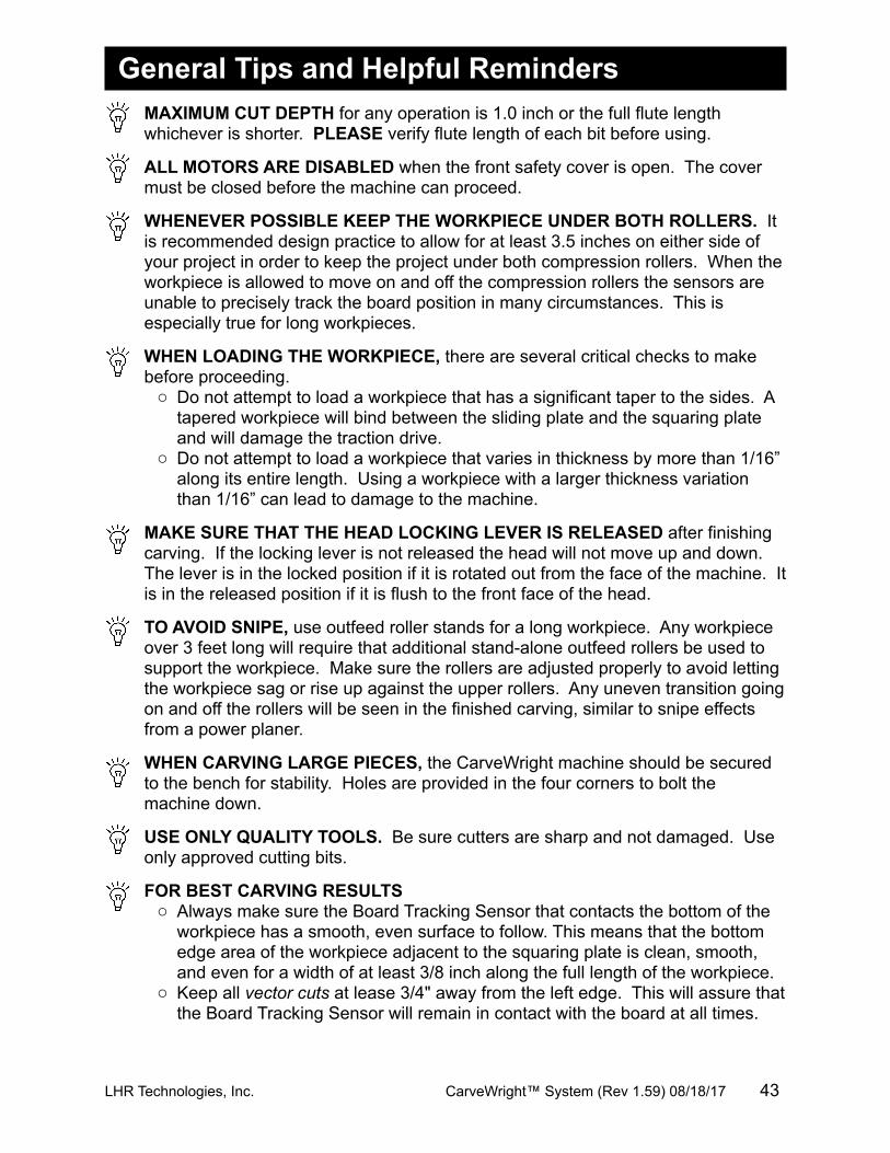
General Tips and Helpful RemindersMAXIMUM CUT DEPTH for any operation is 1.0 inch or the full flute length whichever is shorter. PLEASE verify flute length of each bit before using.
ALL MOTORS ARE DISABLED when the front safety cover is open. The cover must be closed before the machine can proceed.
WHENEVER POSSIBLE KEEP THE WORKPIECE UNDER BOTH ROLLERS. It is recommended design practice to allow for at least 3.5 inches on either side of your project in order to keep the project under both compression rollers. When the workpiece is allowed to move on and off the compression rollers the sensors are unable to precisely track the board position in many circumstances. This is especially true for long workpieces.
WHEN LOADING THE WORKPIECE, there are several critical checks to make before proceeding.o Do not attempt to load a workpiece that has a significant taper to the sides. A
tapered workpiece will bind between the sliding plate and the squaring plate and will damage the traction drive.
o Do not attempt to load a workpiece that varies in thickness by more than 1/16” along its entire length. Using a workpiece with a larger thickness variation than 1/16” can lead to damage to the machine.
MAKE SURE THAT THE HEAD LOCKING LEVER IS RELEASED after finishing carving. If the locking lever is not released the head will not move up and down. The lever is in the locked position if it is rotated out from the face of the machine. It is in the released position if it is flush to the front face of the head.
TO AVOID SNIPE, use outfeed roller stands for a long workpiece. Any workpiece over 3 feet long will require that additional stand-alone outfeed rollers be used to support the workpiece. Make sure the rollers are adjusted properly to avoid letting the workpiece sag or rise up against the upper rollers. Any uneven transition going on and off the rollers will be seen in the finished carving, similar to snipe effects from a power planer.
WHEN CARVING LARGE PIECES, the CarveWright machine should be secured to the bench for stability. Holes are provided in the four corners to bolt the machine down.
USE ONLY QUALITY TOOLS. Be sure cutters are sharp and not damaged. Use only approved cutting bits.
FOR BEST CARVING RESULTSo Always make sure the Board Tracking Sensor that contacts the bottom of the
workpiece has a smooth, even surface to follow. This means that the bottom edge area of the workpiece adjacent to the squaring plate is clean, smooth, and even for a width of at least 3/8 inch along the full length of the workpiece.
o Keep all vector cuts at lease 3/4" away from the left edge. This will assure that the Board Tracking Sensor will remain in contact with the board at all times.
LHR Technologies, Inc. CarveWright™ System (Rev 1.59) 08/18/17 43
o Warped, bowed, or cupped pieces should be used only if this condition is minor and if the Board Tracking Sensor can follow it. A workpiece with slight cups or bows should be inserted curve down.
o Avoid creating very thin features that protrude from the surface of the carving. Very thin features that are raised are prone to chipping.
WHEN CARVING IN PLASTIC, there are several issues to keep in mind.
Carving plastics can be very hard on the machine if the proper material is not used of if the chips are not regularly removed from the machine.
o Only Polycarbonate or Cast Acrylic plastics are approved for use in this machine. Most other common plastics melt during cutting and will damage the machine if used.
o The maximum cut depth for plastics is 0.1 inches per pass.o Plastic shavings are prone to clogging the machine and must be vacuumed
out regularly.o If possible remove any thin protective plastic from the surface to avoid
wrapping it around the spinning bit.o Because of the smooth slick nature of the plastic surface, the workpiece must
be mounted to a backing board so that the Board Tracking Sensor will perform properly.
o Make sure that any hardware used to affix the plastic to the backer board resides outside of the cutting area.
o If cutting in clear plastic the machine may have trouble locating the edges at startup. To avoid this simply place masking tape along the edges of the workpiece.
CLEAR DUST AFTER EACH OPERATION. It is important that any dust on or near the Squaring Plate and the Sliding Guide Plate be removed before starting a cutting operation to ensure that the sensors can find the board edges accurately. A simple wipe will usually suffice. If using compressed air, always make sure to use low-pressure air (<80 psi) around the electronics and sensors. High-pressure air can damage components and actually push dust into them.
MAKE TEST CUTS, when carving a new project test the project on scrap wood to ensure that the settings produce desired results.
SMALL WORKPIECES MUST USE JIG. Any workpiece smaller than 1.5 inches wide x 0.5 inches thick x 7 inches long will require jigging.
TO LOCATE THE MACHINE RUN-TIME, use the Options shortcut key on the keypad to access the information.
TO LOCATE THE SERIAL NUMBER, use the Options shortcut key on the keypad to access the information.
TO LOCATE FIRMWARE VERSION, use the Options shortcut key on the keypad to access the information.
WHEN USING EXTERNAL DUST COLLECTION, make sure that the equipment is grounded according to the manufactured specifications. Electronics failure can occur if these procedures are not followed.
LHR Technologies, Inc. CarveWright™ System (Rev 1.59) 08/18/17 44
WARNING: CUT IN ONLY WOOD, PLASTIC, OR WOOD-LIKE MATERIALS. Do not cut metal, glass, stone, tile or any other hard materials.
WARNING: WHENEVER USING THE 1/8” or 1/16” CUTTING BIT, it is strongly recommended that the Stay Under Rollers option be set to Yes. It is likely that the 1/8” cutting bit will be broken during operations near either end of the workpiece or undesirable stair stepping can occur.
WARNING: NEVER CUT DEEPER THAN THE LENGTH OF THE SHARPENED CUTTING SURFACE OF THE BIT. The maximum cut depth as stated in this Manual is 1" for the straight 1/8" cutting bit. The maximum carving depth for the 1/16" tapered carving bit is 3/4" because that is the length of the sharpened flutes. This max depth rule applies to all bits; you cannot carve deeper than the length of the sharpened cutting surface. If you program the project to go deeper than 3/4" with the carving bit you will most likely damage your machine or bits since the stress on the machine increases exponentially when the bit is not cutting.
BEFORE STARTING, note the orientation of the project as viewed on the computer screen as compared to the orientation of the project as it is being carved on the machine. This is important in the event that a specific orientation or location of the project on the material is desired. See Figure 15 and Figure 16 for a graphical representation of the screen and machine orientations. Also, raster carvings will be completed from the front to the back of the machine.
LHR Technologies, Inc. CarveWright™ System (Rev 1.59) 08/18/17 45
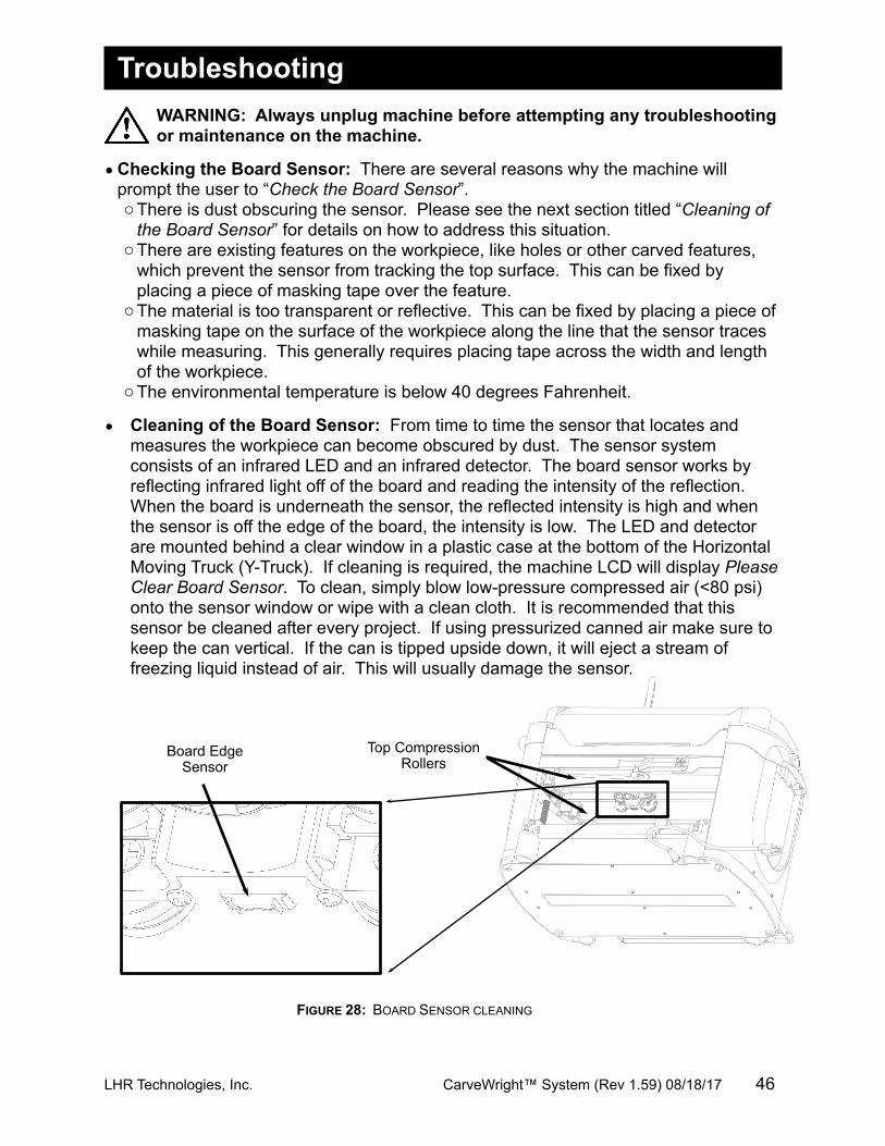
Board EdgeSensor
Top Compression Rollers
TroubleshootingWARNING: Always unplug machine before attempting any troubleshooting or maintenance on the machine.
•Checking the Board Sensor: There are several reasons why the machine will prompt the user to “Check the Board Sensor”. oThere is dust obscuring the sensor. Please see the next section titled “Cleaning of
the Board Sensor” for details on how to address this situation.oThere are existing features on the workpiece, like holes or other carved features,
which prevent the sensor from tracking the top surface. This can be fixed by placing a piece of masking tape over the feature.
oThe material is too transparent or reflective. This can be fixed by placing a piece of masking tape on the surface of the workpiece along the line that the sensor traces while measuring. This generally requires placing tape across the width and length of the workpiece.
oThe environmental temperature is below 40 degrees Fahrenheit.
• Cleaning of the Board Sensor: From time to time the sensor that locates and measures the workpiece can become obscured by dust. The sensor system consists of an infrared LED and an infrared detector. The board sensor works by reflecting infrared light off of the board and reading the intensity of the reflection. When the board is underneath the sensor, the reflected intensity is high and when the sensor is off the edge of the board, the intensity is low. The LED and detector are mounted behind a clear window in a plastic case at the bottom of the Horizontal Moving Truck (Y-Truck). If cleaning is required, the machine LCD will display Please Clear Board Sensor. To clean, simply blow low-pressure compressed air (<80 psi) onto the sensor window or wipe with a clean cloth. It is recommended that this sensor be cleaned after every project. If using pressurized canned air make sure to keep the can vertical. If the can is tipped upside down, it will eject a stream of freezing liquid instead of air. This will usually damage the sensor.
LHR Technologies, Inc. CarveWright™ System (Rev 1.59) 08/18/17 46
FIGURE 28: BOARD SENSOR CLEANING
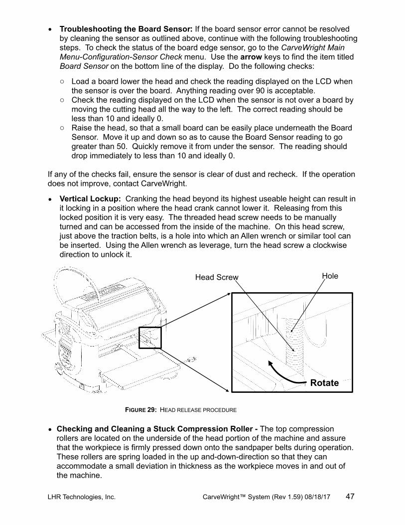
• Troubleshooting the Board Sensor: If the board sensor error cannot be resolved by cleaning the sensor as outlined above, continue with the following troubleshooting steps. To check the status of the board edge sensor, go to the CarveWright Main Menu-Configuration-Sensor Check menu. Use the arrow keys to find the item titled Board Sensor on the bottom line of the display. Do the following checks:
o Load a board lower the head and check the reading displayed on the LCD when the sensor is over the board. Anything reading over 90 is acceptable.
o Check the reading displayed on the LCD when the sensor is not over a board by moving the cutting head all the way to the left. The correct reading should be less than 10 and ideally 0.
o Raise the head, so that a small board can be easily place underneath the Board Sensor. Move it up and down so as to cause the Board Sensor reading to go greater than 50. Quickly remove it from under the sensor. The reading should drop immediately to less than 10 and ideally 0.
If any of the checks fail, ensure the sensor is clear of dust and recheck. If the operation does not improve, contact CarveWright.
• Vertical Lockup: Cranking the head beyond its highest useable height can result in it locking in a position where the head crank cannot lower it. Releasing from this locked position it is very easy. The threaded head screw needs to be manually turned and can be accessed from the inside of the machine. On this head screw, just above the traction belts, is a hole into which an Allen wrench or similar tool can be inserted. Using the Allen wrench as leverage, turn the head screw a clockwise direction to unlock it.
• Checking and Cleaning a Stuck Compression Roller - The top compression rollers are located on the underside of the head portion of the machine and assure that the workpiece is firmly pressed down onto the sandpaper belts during operation. These rollers are spring loaded in the up and-down-direction so that they can accommodate a small deviation in thickness as the workpiece moves in and out of the machine.
LHR Technologies, Inc. CarveWright™ System (Rev 1.59) 08/18/17 47
FIGURE 29: HEAD RELEASE PROCEDURE
Head Screw Hole
Rotate
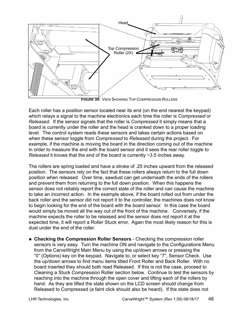
Each roller has a position sensor located near its end (on the end nearest the keypad) which relays a signal to the machine electronics each time the roller is Compressed or Released. If the sensor signals that the roller is Compressed it simply means that a board is currently under the roller and the head is cranked down to a proper loading level. The control system reads these sensors and takes certain actions based on when these sensor toggle from Compressed to Released during the project. For example, if the machine is moving the board in the direction coming out of the machine in order to measure the end with the board sensor and it sees the rear roller toggle to Released it knows that the end of the board is currently ~3.5 inches away.
The rollers are spring loaded and have a stroke of .25 inches upward from the released position. The sensors rely on the fact that these rollers always return to the full down position when released. Over time, sawdust can get underneath the ends of the rollers and prevent them from returning to the full down position. When this happens the sensor does not reliably report the correct state of the roller and can cause the machine to take an incorrect action. In the example above, if the board rolled out from under the back roller and the sensor did not report it to the controller, the machines does not know to begin looking for the end of the board with the board sensor. In this case the board would simply be moved all the way out of the front of the machine. Conversely, if the machine expects the roller to be released and the sensor does not report it at the expected time, it will report a Roller Stuck error. Again the most likely reason for this is dust under the end of the roller.
• Checking the Compression Roller Sensors - Checking the compression roller sensors is very easy. Turn the machine ON and navigate to the Configurations Menu from the CarveWright Main Menu by using the up/down arrows or pressing the “0” (Options) key on the keypad. Navigate to, or select key “7”, Sensor Check. Use the up/down arrows to find menu items titled Front Roller and Back Roller. With no board inserted they should both read Released. If this is not the case, proceed to Cleaning a Stuck Compression Roller section below. Continue to test the sensors by reaching into the machine through the open cover and lifting each of the rollers by hand. As they are lifted the state shown on the LCD screen should change from Released to Compressed (a faint click should also be heard). If the state does not
LHR Technologies, Inc. CarveWright™ System (Rev 1.59) 08/18/17 48
FIGURE 30: VIEW SHOWING TOP COMPRESSION ROLLERS
Head
Top Compression Roller (2X)
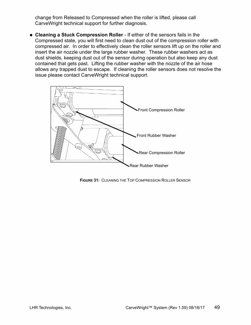
change from Released to Compressed when the roller is lifted, please call CarveWright technical support for further diagnosis.
• Cleaning a Stuck Compression Roller - If either of the sensors fails in the Compressed state, you will first need to clean dust out of the compression roller with compressed air. In order to effectively clean the roller sensors lift up on the roller and insert the air nozzle under the large rubber washer. These rubber washers act as dust shields, keeping dust out of the sensor during operation but also keep any dust contained that gets past. Lifting the rubber washer with the nozzle of the air hose allows any trapped dust to escape. If cleaning the roller sensors does not resolve the issue please contact CarveWright technical support.
LHR Technologies, Inc. CarveWright™ System (Rev 1.59) 08/18/17 49
FIGURE 31: CLEANING THE TOP COMPRESSION ROLLER SENSOR
Rear Compression Roller
Front Compression Roller
Rear Rubber Washer
Front Rubber Washer
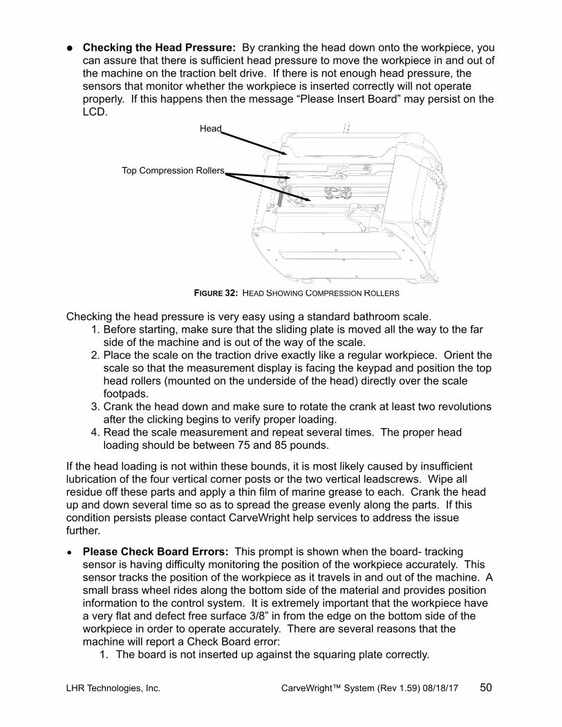
• Checking the Head Pressure: By cranking the head down onto the workpiece, you can assure that there is sufficient head pressure to move the workpiece in and out of the machine on the traction belt drive. If there is not enough head pressure, the sensors that monitor whether the workpiece is inserted correctly will not operate properly. If this happens then the message “Please Insert Board” may persist on the LCD.
Checking the head pressure is very easy using a standard bathroom scale.1. Before starting, make sure that the sliding plate is moved all the way to the far
side of the machine and is out of the way of the scale.2. Place the scale on the traction drive exactly like a regular workpiece. Orient the
scale so that the measurement display is facing the keypad and position the top head rollers (mounted on the underside of the head) directly over the scale footpads.
3. Crank the head down and make sure to rotate the crank at least two revolutions after the clicking begins to verify proper loading.
4. Read the scale measurement and repeat several times. The proper head loading should be between 75 and 85 pounds.
If the head loading is not within these bounds, it is most likely caused by insufficient lubrication of the four vertical corner posts or the two vertical leadscrews. Wipe all residue off these parts and apply a thin film of marine grease to each. Crank the head up and down several time so as to spread the grease evenly along the parts. If this condition persists please contact CarveWright help services to address the issue further.
• Please Check Board Errors: This prompt is shown when the board- tracking sensor is having difficulty monitoring the position of the workpiece accurately. This sensor tracks the position of the workpiece as it travels in and out of the machine. A small brass wheel rides along the bottom side of the material and provides position information to the control system. It is extremely important that the workpiece have a very flat and defect free surface 3/8” in from the edge on the bottom side of the workpiece in order to operate accurately. There are several reasons that the machine will report a Check Board error:
1. The board is not inserted up against the squaring plate correctly.
LHR Technologies, Inc. CarveWright™ System (Rev 1.59) 08/18/17 50
FIGURE 32: HEAD SHOWING COMPRESSION ROLLERS
Head
Top Compression Rollers
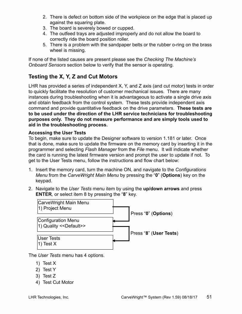
2. There is defect on bottom side of the workpiece on the edge that is placed up against the squaring plate.
3. The board is severely bowed or cupped.4. The outfeed trays are adjusted improperly and do not allow the board to
correctly ride the board position roller.5. There is a problem with the sandpaper belts or the rubber o-ring on the brass
wheel is missing.
If none of the listed causes are present please see the Checking The Machine’s Onboard Sensors section below to verify that the sensor is operating.
Testing the X, Y, Z and Cut MotorsLHR has provided a series of independent X, Y, and Z axis (and cut motor) tests in order to quickly facilitate the resolution of customer mechanical issues. There are many instances during troubleshooting when it is advantageous to activate a single drive axis and obtain feedback from the control system. These tests provide independent axis command and provide quantitative feedback on the drive parameters. These tests are to be used under the direction of the LHR service technicians for troubleshooting purposes only. They do not measure performance and are simply tools used to aid in the troubleshooting process.Accessing the User TestsTo begin, make sure to update the Designer software to version 1.181 or later. Once that is done, make sure to update the firmware on the memory card by inserting it in the programmer and selecting Flash Manager from the File menu. It will indicate whether the card is running the latest firmware version and prompt the user to update if not. To get to the User Tests menu, follow the instructions and flow chart below:
1. Insert the memory card, turn the machine ON, and navigate to the Configurations Menu from the CarveWright Main Menu by pressing the “0” (Options) key on the keypad.
2. Navigate to the User Tests menu item by using the up/down arrows and press ENTER, or select item 8 by pressing the “8” key.
The User Tests menu has 4 options.
1) Test X2) Test Y3) Test Z4) Test Cut Motor
LHR Technologies, Inc. CarveWright™ System (Rev 1.59) 08/18/17 51
CarveWright Main Menu1) Project Menu
Configuration Menu1) Quality <<Default>>
User Tests1) Test X
Press “0” (Options)
Press “8” (User Tests)
Testing the X DriveIn order to test only the X drive (the sandpaper or rubber drive belts) choose the first option in the User Tests menu labeled Test X. The display will instruct the user to remove the bit and board from the machine. As an additional precaution, move the Z truck to the center of its left/right travel and to the top of its up/down travel and crank the head up a couple of inches. The machine will drive the belts both forward and backward. Diagnostic data is shown on the LCD. Report this data to the LHR technician ONLY if requested.
Testing the Y DriveIn order to test only the Y drive (the left to right motion of the cutting truck) choose the second option in the User Tests menu labeled Test Y. The display will instruct the user to remove the bit and board from the machine. As an additional precaution, move the Z truck to the top of its up/down travel and crank the head up a couple of inches.
The machine will move the cutting truck to the left of the machine to find the home position. It will then slowly move the cutting truck from the left side of the machine to the right and back. Diagnostic data is shown on the LCD. Report this data to the LHR technician ONLY if requested.
Testing the Z DriveIn order to test only the Z drive (the up and down motion of the cutting truck) choose the third option in the User Tests menu labeled Test Z. The display will instruct the user to remove the bit and board from the machine. As an additional precaution, move the Z truck to the center of its left/right travel and crank the head up a couple of inches.
The machine will move the cutting truck upward to find home. Then it will slowly move down to the bottom of travel, reverse and come back to the top position. Diagnostic data is shown on the LCD. Report this data to the LHR technician ONLY if requested.
Testing the Cut MotorThere are many times when a customer may want to test the cut motor directly without having to spend the time setting up a project.
The fourth test will simply command the cut motor to switch on. The machine will home as normal, then move to the center on its left/right travel and prompt the user to load “Any size board” and remove all bits from the machine. Press any key to turn the cut motor on and press any key to stop the motor.
Again, these tests are for use in diagnosing machine issues at the direction of LHR technicians. They are tools that are used to aid our technicians and are not used to test machine performance.
LHR Technologies, Inc. CarveWright™ System (Rev 1.59) 08/18/17 52
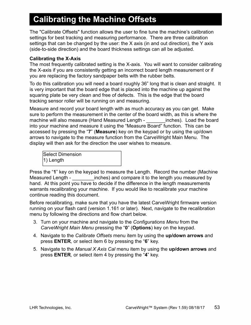
Select Dimension1) Length
Calibrating the Machine OffsetsThe "Calibrate Offsets" function allows the user to fine tune the machine’s calibration settings for best tracking and measuring performance. There are three calibration settings that can be changed by the user: the X axis (in and out direction), the Y axis (side-to-side direction) and the board thickness settings can all be adjusted.
Calibrating the X-AxisThe most frequently calibrated setting is the X-axis. You will want to consider calibrating the X-axis if you are consistently getting an incorrect board length measurement or if you are replacing the factory sandpaper belts with the rubber belts. To do this calibration you will need a board roughly 36” long that is clean and straight. It is very important that the board edge that is placed into the machine up against the squaring plate be very clean and free of defects. This is the edge that the board tracking sensor roller will be running on and measuring.Measure and record your board length with as much accuracy as you can get. Make sure to perform the measurement in the center of the board width, as this is where the machine will also measure (Hand Measured Length - _______inches). Load the board into your machine and measure it using the “Measure Board” function. This can be accessed by pressing the “7” (Measure) key on the keypad or by using the up/down arrows to navigate to the measure function from the CarveWright Main Menu. The display will then ask for the direction the user wishes to measure.
Press the “1” key on the keypad to measure the Length. Record the number (Machine Measured Length - ________inches) and compare it to the length you measured by hand. At this point you have to decide if the difference in the length measurements warrants recalibrating your machine. If you would like to recalibrate your machine continue reading this document.Before recalibrating, make sure that you have the latest CarveWright firmware version running on your flash card (version 1.161 or later). Next, navigate to the recalibration menu by following the directions and flow chart below.
3. Turn on your machine and navigate to the Configurations Menu from the CarveWright Main Menu pressing the “0” (Options) key on the keypad.
4. Navigate to the Calibrate Offsets menu item by using the up/down arrows and press ENTER, or select item 6 by pressing the “6” key.
5. Navigate to the Manual X Axis Cal menu item by using the up/down arrows and press ENTER, or select item 4 by pressing the “4” key.
LHR Technologies, Inc. CarveWright™ System (Rev 1.59) 08/18/17 53
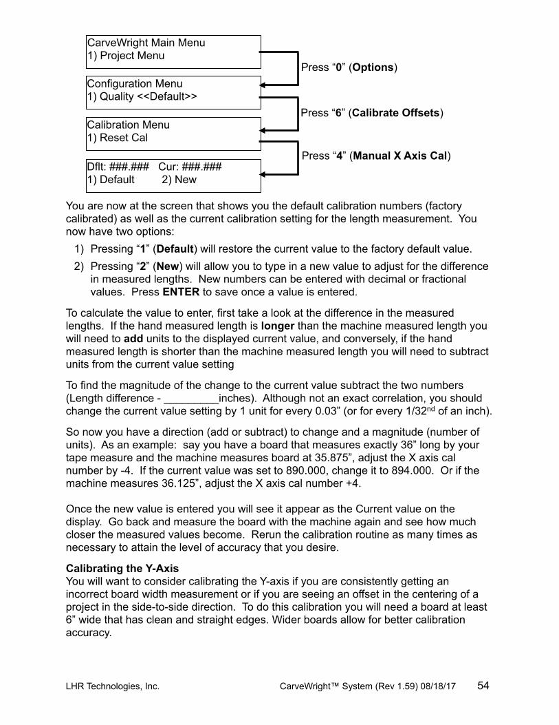
You are now at the screen that shows you the default calibration numbers (factory calibrated) as well as the current calibration setting for the length measurement. You now have two options:
1) Pressing “1” (Default) will restore the current value to the factory default value.2) Pressing “2” (New) will allow you to type in a new value to adjust for the difference
in measured lengths. New numbers can be entered with decimal or fractional values. Press ENTER to save once a value is entered.
To calculate the value to enter, first take a look at the difference in the measured lengths. If the hand measured length is longer than the machine measured length you will need to add units to the displayed current value, and conversely, if the hand measured length is shorter than the machine measured length you will need to subtract units from the current value setting
To find the magnitude of the change to the current value subtract the two numbers (Length difference - _________inches). Although not an exact correlation, you should change the current value setting by 1 unit for every 0.03” (or for every 1/32nd of an inch).
So now you have a direction (add or subtract) to change and a magnitude (number of units). As an example: say you have a board that measures exactly 36” long by your tape measure and the machine measures board at 35.875”, adjust the X axis cal number by -4. If the current value was set to 890.000, change it to 894.000. Or if the machine measures 36.125”, adjust the X axis cal number +4.
Once the new value is entered you will see it appear as the Current value on the display. Go back and measure the board with the machine again and see how much closer the measured values become. Rerun the calibration routine as many times as necessary to attain the level of accuracy that you desire.
Calibrating the Y-AxisYou will want to consider calibrating the Y-axis if you are consistently getting an incorrect board width measurement or if you are seeing an offset in the centering of a project in the side-to-side direction. To do this calibration you will need a board at least 6” wide that has clean and straight edges. Wider boards allow for better calibration accuracy.
LHR Technologies, Inc. CarveWright™ System (Rev 1.59) 08/18/17 54
CarveWright Main Menu1) Project Menu
Configuration Menu1) Quality <<Default>>
Calibration Menu1) Reset Cal
Dflt: ###.### Cur: ###.###1) Default 2) New
Press “0” (Options)
Press “6” (Calibrate Offsets)
Press “4” (Manual X Axis Cal)
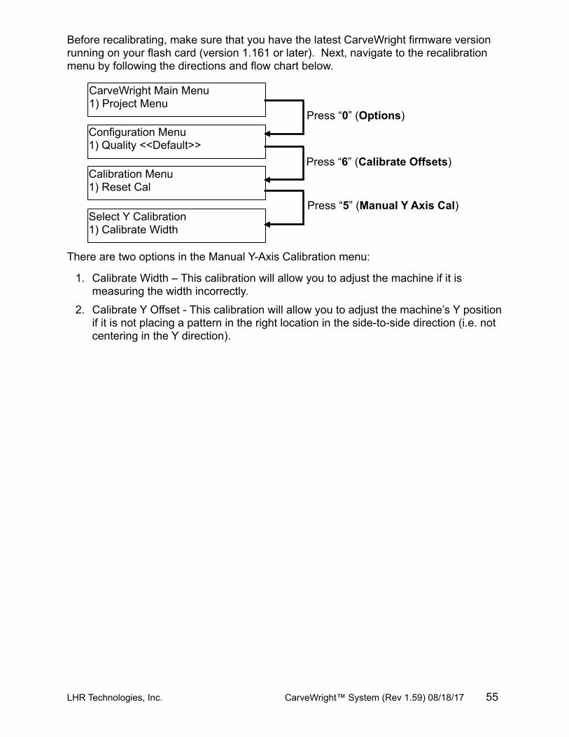
Before recalibrating, make sure that you have the latest CarveWright firmware version running on your flash card (version 1.161 or later). Next, navigate to the recalibration menu by following the directions and flow chart below.
There are two options in the Manual Y-Axis Calibration menu:
1. Calibrate Width – This calibration will allow you to adjust the machine if it is measuring the width incorrectly.
2. Calibrate Y Offset - This calibration will allow you to adjust the machine’s Y position if it is not placing a pattern in the right location in the side-to-side direction (i.e. not centering in the Y direction).
LHR Technologies, Inc. CarveWright™ System (Rev 1.59) 08/18/17 55
CarveWright Main Menu1) Project Menu
Configuration Menu1) Quality <<Default>>
Calibration Menu1) Reset Cal
Select Y Calibration1) Calibrate Width
Press “0” (Options)
Press “6” (Calibrate Offsets)
Press “5” (Manual Y Axis Cal)
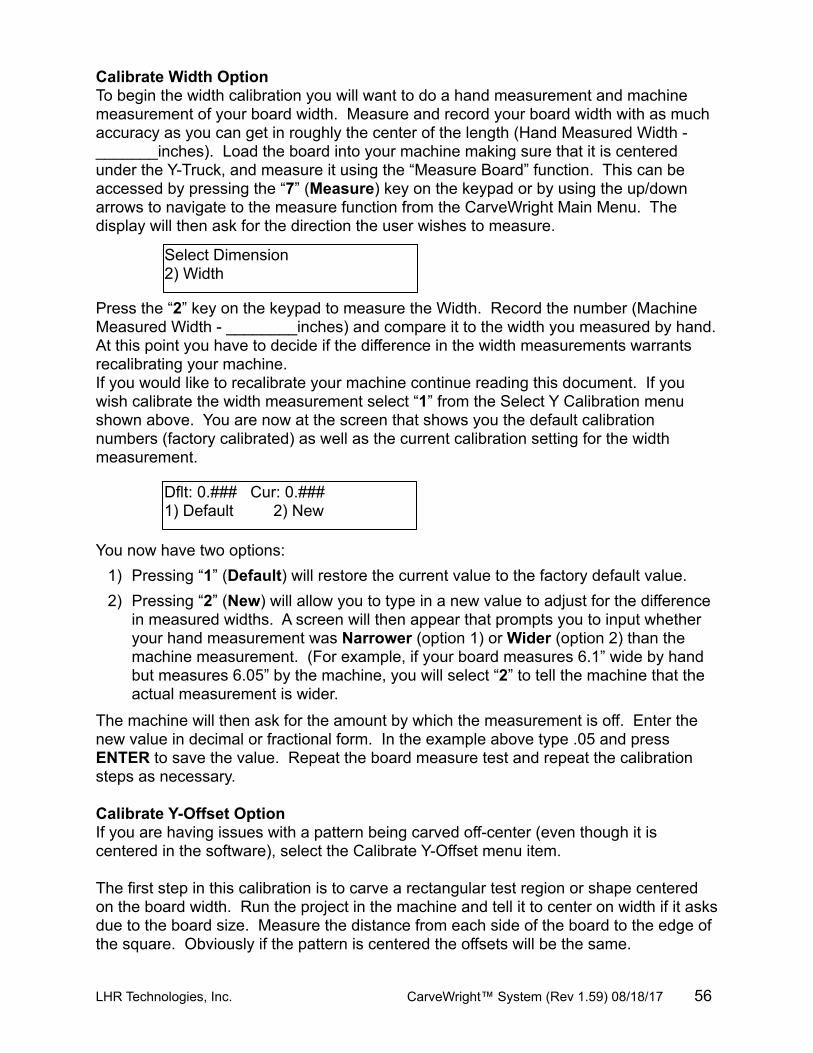
Dflt: 0.### Cur: 0.###1) Default 2) New
Select Dimension2) Width
Calibrate Width Option To begin the width calibration you will want to do a hand measurement and machine measurement of your board width. Measure and record your board width with as much accuracy as you can get in roughly the center of the length (Hand Measured Width - _______inches). Load the board into your machine making sure that it is centered under the Y-Truck, and measure it using the “Measure Board” function. This can be accessed by pressing the “7” (Measure) key on the keypad or by using the up/down arrows to navigate to the measure function from the CarveWright Main Menu. The display will then ask for the direction the user wishes to measure.
Press the “2” key on the keypad to measure the Width. Record the number (Machine Measured Width - ________inches) and compare it to the width you measured by hand. At this point you have to decide if the difference in the width measurements warrants recalibrating your machine. If you would like to recalibrate your machine continue reading this document. If you wish calibrate the width measurement select “1” from the Select Y Calibration menu shown above. You are now at the screen that shows you the default calibration numbers (factory calibrated) as well as the current calibration setting for the width measurement.
You now have two options:1) Pressing “1” (Default) will restore the current value to the factory default value.2) Pressing “2” (New) will allow you to type in a new value to adjust for the difference
in measured widths. A screen will then appear that prompts you to input whether your hand measurement was Narrower (option 1) or Wider (option 2) than the machine measurement. (For example, if your board measures 6.1” wide by hand but measures 6.05” by the machine, you will select “2” to tell the machine that the actual measurement is wider.
The machine will then ask for the amount by which the measurement is off. Enter the new value in decimal or fractional form. In the example above type .05 and press ENTER to save the value. Repeat the board measure test and repeat the calibration steps as necessary.
Calibrate Y-Offset OptionIf you are having issues with a pattern being carved off-center (even though it is centered in the software), select the Calibrate Y-Offset menu item.
The first step in this calibration is to carve a rectangular test region or shape centered on the board width. Run the project in the machine and tell it to center on width if it asks due to the board size. Measure the distance from each side of the board to the edge of the square. Obviously if the pattern is centered the offsets will be the same.
LHR Technologies, Inc. CarveWright™ System (Rev 1.59) 08/18/17 56
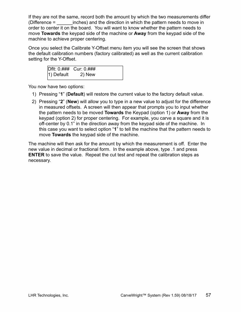
Dflt: 0.### Cur: 0.###1) Default 2) New
If they are not the same, record both the amount by which the two measurements differ (Difference = ______inches) and the direction in which the pattern needs to move in order to center it on the board. You will want to know whether the pattern needs to move Towards the keypad side of the machine or Away from the keypad side of the machine to achieve proper centering.
Once you select the Calibrate Y-Offset menu item you will see the screen that shows the default calibration numbers (factory calibrated) as well as the current calibration setting for the Y-Offset.
You now have two options:1) Pressing “1” (Default) will restore the current value to the factory default value.2) Pressing “2” (New) will allow you to type in a new value to adjust for the difference
in measured offsets. A screen will then appear that prompts you to input whether the pattern needs to be moved Towards the Keypad (option 1) or Away from the keypad (option 2) for proper centering. For example, you carve a square and it is off-center by 0.1” in the direction away from the keypad side of the machine. In this case you want to select option “1” to tell the machine that the pattern needs to move Towards the keypad side of the machine.
The machine will then ask for the amount by which the measurement is off. Enter the new value in decimal or fractional form. In the example above, type .1 and press ENTER to save the value. Repeat the cut test and repeat the calibration steps as necessary.
LHR Technologies, Inc. CarveWright™ System (Rev 1.59) 08/18/17 57
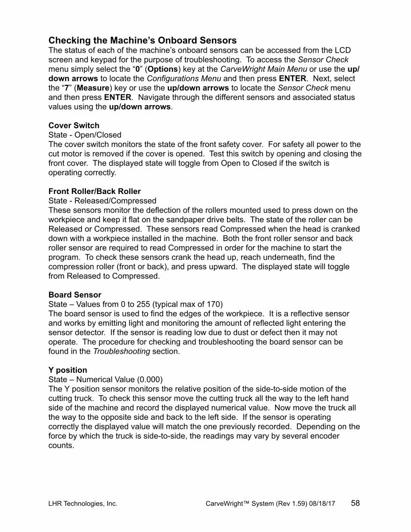
Checking the Machine’s Onboard SensorsThe status of each of the machine’s onboard sensors can be accessed from the LCD screen and keypad for the purpose of troubleshooting. To access the Sensor Check menu simply select the “0” (Options) key at the CarveWright Main Menu or use the up/down arrows to locate the Configurations Menu and then press ENTER. Next, select the “7” (Measure) key or use the up/down arrows to locate the Sensor Check menu and then press ENTER. Navigate through the different sensors and associated status values using the up/down arrows.
Cover SwitchState - Open/ClosedThe cover switch monitors the state of the front safety cover. For safety all power to the cut motor is removed if the cover is opened. Test this switch by opening and closing the front cover. The displayed state will toggle from Open to Closed if the switch is operating correctly.
Front Roller/Back RollerState - Released/CompressedThese sensors monitor the deflection of the rollers mounted used to press down on the workpiece and keep it flat on the sandpaper drive belts. The state of the roller can be Released or Compressed. These sensors read Compressed when the head is cranked down with a workpiece installed in the machine. Both the front roller sensor and back roller sensor are required to read Compressed in order for the machine to start the program. To check these sensors crank the head up, reach underneath, find the compression roller (front or back), and press upward. The displayed state will toggle from Released to Compressed.
Board SensorState – Values from 0 to 255 (typical max of 170)The board sensor is used to find the edges of the workpiece. It is a reflective sensor and works by emitting light and monitoring the amount of reflected light entering the sensor detector. If the sensor is reading low due to dust or defect then it may not operate. The procedure for checking and troubleshooting the board sensor can be found in the Troubleshooting section.
Y positionState – Numerical Value (0.000)The Y position sensor monitors the relative position of the side-to-side motion of the cutting truck. To check this sensor move the cutting truck all the way to the left hand side of the machine and record the displayed numerical value. Now move the truck all the way to the opposite side and back to the left side. If the sensor is operating correctly the displayed value will match the one previously recorded. Depending on the force by which the truck is side-to-side, the readings may vary by several encoder counts.
LHR Technologies, Inc. CarveWright™ System (Rev 1.59) 08/18/17 58
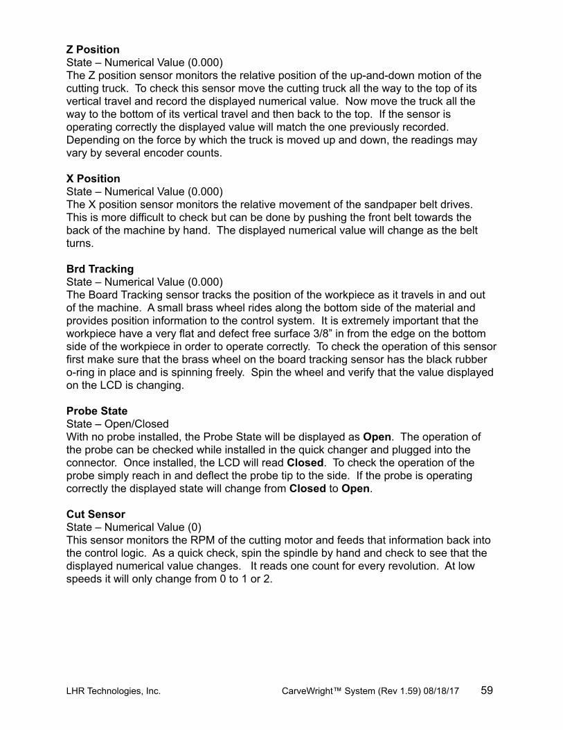
Z PositionState – Numerical Value (0.000)The Z position sensor monitors the relative position of the up-and-down motion of the cutting truck. To check this sensor move the cutting truck all the way to the top of its vertical travel and record the displayed numerical value. Now move the truck all the way to the bottom of its vertical travel and then back to the top. If the sensor is operating correctly the displayed value will match the one previously recorded. Depending on the force by which the truck is moved up and down, the readings may vary by several encoder counts.
X Position State – Numerical Value (0.000)The X position sensor monitors the relative movement of the sandpaper belt drives. This is more difficult to check but can be done by pushing the front belt towards the back of the machine by hand. The displayed numerical value will change as the belt turns.
Brd TrackingState – Numerical Value (0.000)The Board Tracking sensor tracks the position of the workpiece as it travels in and out of the machine. A small brass wheel rides along the bottom side of the material and provides position information to the control system. It is extremely important that the workpiece have a very flat and defect free surface 3/8” in from the edge on the bottom side of the workpiece in order to operate correctly. To check the operation of this sensor first make sure that the brass wheel on the board tracking sensor has the black rubber o-ring in place and is spinning freely. Spin the wheel and verify that the value displayed on the LCD is changing.
Probe StateState – Open/ClosedWith no probe installed, the Probe State will be displayed as Open. The operation of the probe can be checked while installed in the quick changer and plugged into the connector. Once installed, the LCD will read Closed. To check the operation of the probe simply reach in and deflect the probe tip to the side. If the probe is operating correctly the displayed state will change from Closed to Open.
Cut SensorState – Numerical Value (0)This sensor monitors the RPM of the cutting motor and feeds that information back into the control logic. As a quick check, spin the spindle by hand and check to see that the displayed numerical value changes. It reads one count for every revolution. At low speeds it will only change from 0 to 1 or 2.
LHR Technologies, Inc. CarveWright™ System (Rev 1.59) 08/18/17 59

For More Information visitwww.carvewright.com
For Sales, Technical or Software Support
Call 713-473-6572Or email [email protected]