Embed Size (px)
Citation preview
Rev.1 - 1 - 11/23/2009 Serge Simon
Cartwall Interface and construction details by R.O.M. 106.5 FM
Cartwall Interface and construction details
by R.O.M. 106.5 FM
Table of Contents: Purpose ..................................................................................................................... 2 Scope ........................................................................................................................ 2 Software Interfaces.................................................................................................... 3 mAirList® Notification Scripts ................................................................................. 5
mAirList® Startup Script................................................................................... 6 mAirList® Exit Script ....................................................................................... 9 Cart Player Mode Script....................................................................................10 Cart Player EOF Script .....................................................................................12 Player Mode Script ...........................................................................................13 Player EOF Script.............................................................................................14 OffAir Script ....................................................................................................15 OnAir Script .....................................................................................................16 AutomationOff Script .......................................................................................17 AutomationOn Script........................................................................................18
LED Interface driver circuit......................................................................................19 Multicolor LED Pinout .....................................................................................19
Pushbuttons ..............................................................................................................20 Housing and Gamepad .............................................................................................21 Component mounting ...............................................................................................24 Wiring......................................................................................................................25 Printer Port Connector Wiring ..................................................................................26 Printer Port Interface Assembly................................................................................27 Module Mounting.....................................................................................................27 Final Wiring .............................................................................................................28 Testing .....................................................................................................................29
Rev.1 - 2 - 11/23/2009 Serge Simon
Cartwall Interface and construction details by R.O.M. 106.5 FM
Purpose This document covers the construction and interface details for a low-cost interface keyboard that might be used with mAirList® studio automation software. Initial design is based on a 6 button keyboard with illuminated indicators for 2 players and 4 carts. Two additional multicolor LEDs shall indicate the Off-/OnAir Status and the Automation/Assist mode.
Scope The keyboard shall control the 2 players and 4 carts configured in mAirList® via a 6-button USB gamepad. The LEDs in the buttons shall be controlled via the PCs printer port using a ULN2803 as driver in order to prevent any damage to the port. The keyboard housing shall provide an external USB port that can be used to access playlists or other files from mAirList® during the shows. Therefore a USB-hub will be mounted in the housing in order to provide an external port, a port for the 6-button gamepad and power to the parallel port driver and the LEDs. A standard USB port can provide up to 500 mA wich should be sufficient for this type of application. Measurements revealed the following:
- USB-hub : 75 mA - MiniPad: 11 mA - Memorystick: 70 mA maximum when writing
There will be some 300 mA left to drive the LEDs. If we consider using LP-LEDs or not it will be sufficient in either case. So here we will head for standard LEDs that will be limited to 11 mA each. The total current used off the USB port will be somewhere around 270 mA.
Rev.1 - 3 - 11/23/2009 Serge Simon
Cartwall Interface and construction details by R.O.M. 106.5 FM
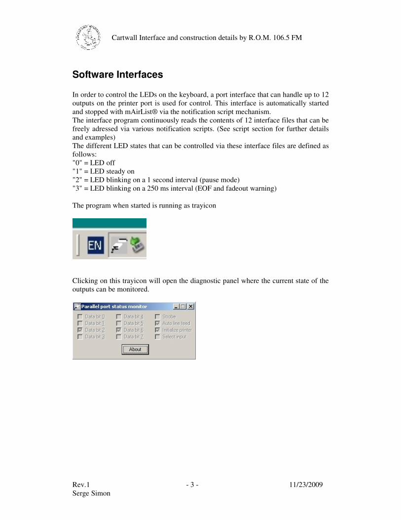
Software Interfaces In order to control the LEDs on the keyboard, a port interface that can handle up to 12 outputs on the printer port is used for control. This interface is automatically started and stopped with mAirList® via the notification script mechanism. The interface program continuously reads the contents of 12 interface files that can be freely adressed via various notification scripts. (See script section for further details and examples) The different LED states that can be controlled via these interface files are defined as follows: "0" = LED off "1" = LED steady on "2" = LED blinking on a 1 second interval (pause mode) "3" = LED blinking on a 250 ms interval (EOF and fadeout warning) The program when started is running as trayicon
Clicking on this trayicon will open the diagnostic panel where the current state of the outputs can be monitored.
Rev.1 - 4 - 11/23/2009 Serge Simon
Cartwall Interface and construction details by R.O.M. 106.5 FM
The I/O assignement of the LEDs will be as follows:
- Cart players 1-4 play/pause/stop will be data output bit 0 – 3 (DF_0.txt – DF_3.txt) (D1 – D4)
- Player 1-2 play pause/stop will be data output bit 4-5 (DF_4.txt – DF_5.txt) (D5, D6)
- OffAir mode will be red blinking wired to data output bit 6 (DF_6.txt) (D7-R) - OnAir mode will be green steady wired to data output bit 7 (DF_7.txt) (D7-G) - AutomationOff mode will be red steady wired to control register output bit 0
(strobe) (DF_8.txt) (D8-R) - AutomationOn mode will be green steady wired to control register output bit 1
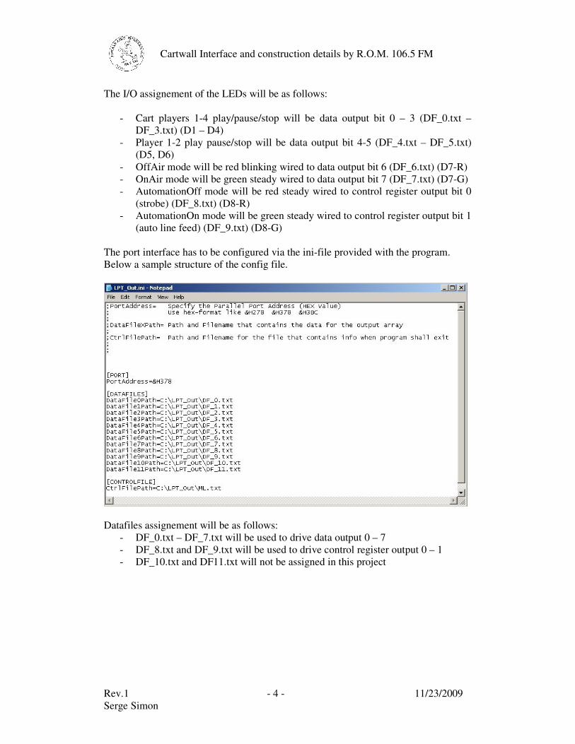
(auto line feed) (DF_9.txt) (D8-G) The port interface has to be configured via the ini-file provided with the program. Below a sample structure of the config file.
Datafiles assignement will be as follows:
- DF_0.txt – DF_7.txt will be used to drive data output 0 – 7 - DF_8.txt and DF_9.txt will be used to drive control register output 0 – 1 - DF_10.txt and DF11.txt will not be assigned in this project
Rev.1 - 5 - 11/23/2009 Serge Simon
Cartwall Interface and construction details by R.O.M. 106.5 FM
mAirList® Notification Scripts In order to interface the printer port program with the correct data, some scripts are required within mAirList®:
- Startup script that launches the printer port program - Script that notifies the printer port program that mAirList® is exiting - Scripts for player and carts that write their current state to a file - Scripts for Off-/OnAir status - Scripts for AutomationOn/Assist mode
Rev.1 - 6 - 11/23/2009 Serge Simon
Cartwall Interface and construction details by R.O.M. 106.5 FM
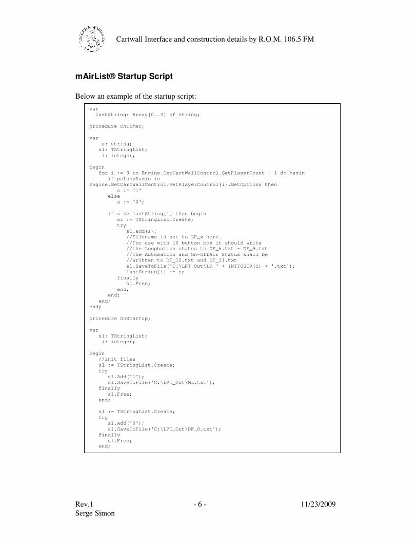
mAirList® Startup Script Below an example of the startup script:
var lastString: Array[0..3] of string; procedure OnTimer; var s: string; sl: TStringList; i: integer; begin for i := 0 to Engine.GetCartWallControl.GetPlayerCount - 1 do begin if poLoopAudio in Engine.GetCartWallControl.GetPlayerControl(i).GetOptions then s := '1' else s := '0'; if s <> lastString[i] then begin sl := TStringList.Create; try sl.add(s); //Filename is set to LP_x here. //For use with 10 button box it should write //the Loopbutton status to DF_6.txt - DF_9.txt //The Automation and On-OffAir Status shall be //written to DF_10.txt and DF_11.txt sl.SaveToFile('C:\LPT_Out\LP_' + INTTOSTR(i) + '.txt'); lastString[i] := s; finally sl.Free; end; end; end; end; procedure OnStartup; var sl: TStringList; i: integer; begin //init files sl := TStringList.Create; try sl.Add('1'); sl.SaveToFile('C:\LPT_Out\ML.txt'); finally sl.Free; end; sl := TStringList.Create; try sl.Add('0'); sl.SaveToFile('C:\LPT_Out\DF_0.txt'); finally sl.Free; end;
Rev.1 - 7 - 11/23/2009 Serge Simon
Cartwall Interface and construction details by R.O.M. 106.5 FM
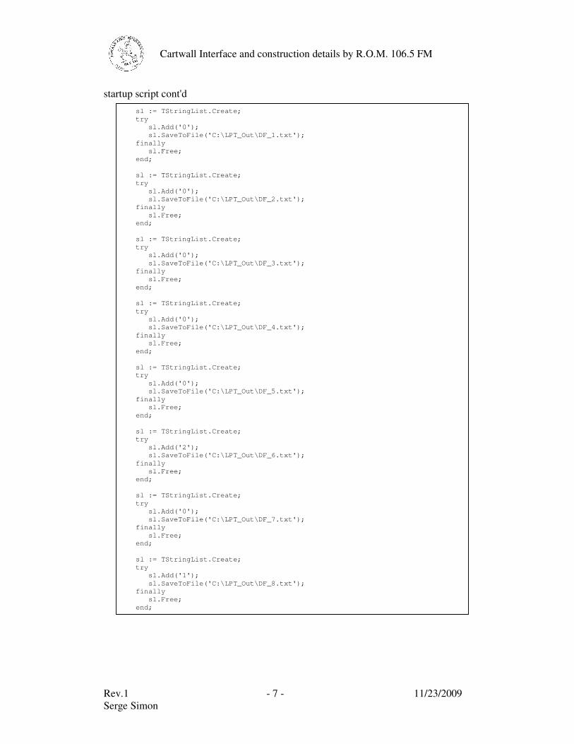
startup script cont'd
sl := TStringList.Create; try sl.Add('0'); sl.SaveToFile('C:\LPT_Out\DF_1.txt'); finally sl.Free; end; sl := TStringList.Create; try sl.Add('0'); sl.SaveToFile('C:\LPT_Out\DF_2.txt'); finally sl.Free; end; sl := TStringList.Create; try sl.Add('0'); sl.SaveToFile('C:\LPT_Out\DF_3.txt'); finally sl.Free; end; sl := TStringList.Create; try sl.Add('0'); sl.SaveToFile('C:\LPT_Out\DF_4.txt'); finally sl.Free; end; sl := TStringList.Create; try sl.Add('0'); sl.SaveToFile('C:\LPT_Out\DF_5.txt'); finally sl.Free; end; sl := TStringList.Create; try sl.Add('2'); sl.SaveToFile('C:\LPT_Out\DF_6.txt'); finally sl.Free; end; sl := TStringList.Create; try sl.Add('0'); sl.SaveToFile('C:\LPT_Out\DF_7.txt'); finally sl.Free; end; sl := TStringList.Create; try sl.Add('1'); sl.SaveToFile('C:\LPT_Out\DF_8.txt'); finally sl.Free; end;
Rev.1 - 8 - 11/23/2009 Serge Simon
Cartwall Interface and construction details by R.O.M. 106.5 FM
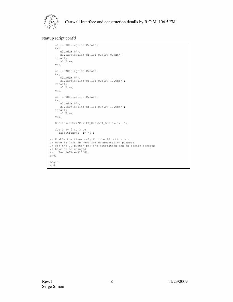
startup script cont'd
sl := TStringList.Create; try sl.Add('0'); sl.SaveToFile('C:\LPT_Out\DF_9.txt'); finally sl.Free; end; sl := TStringList.Create; try sl.Add('0'); sl.SaveToFile('C:\LPT_Out\DF_10.txt'); finally sl.Free; end; sl := TStringList.Create; try sl.Add('0'); sl.SaveToFile('C:\LPT_Out\DF_11.txt'); finally sl.Free; end; ShellExecute('C:\LPT_Out\LPT_Out.exe', ''); for i := 0 to 3 do lastString[i] := '0'; // Enable the timer only for the 10 button box // code is left in here for documentation purpose // for the 10 button box the automation and on-offair scripts // have to be changed // EnableTimer(1000); end; begin end.
Rev.1 - 9 - 11/23/2009 Serge Simon
Cartwall Interface and construction details by R.O.M. 106.5 FM
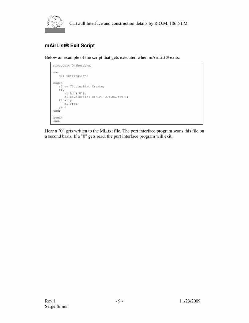
mAirList® Exit Script Below an example of the script that gets executed when mAirList® exits:
Here a "0" gets written to the ML.txt file. The port interface program scans this file on a second basis. If a "0" gets read, the port interface program will exit.
procedure OnShutdown; var sl: TStringList; begin sl := TStringList.Create; try sl.Add('0'); sl.SaveToFile('C:\LPT_Out\ML.txt'); finally sl.Free; ;end end; begin end.
Rev.1 - 10 - 11/23/2009 Serge Simon
Cartwall Interface and construction details by R.O.M. 106.5 FM
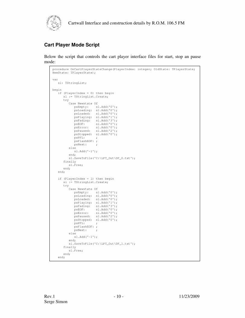
Cart Player Mode Script Below the script that controls the cart player interface files for start, stop an pause mode:
procedure OnCartPlayerStateChange(PlayerIndex: integer; OldState: TPlayerState; NewState: TPlayerState); var sl: TStringList; begin if (PlayerIndex = 0) then begin sl := TStringList.Create; try Case Newstate Of psEmpty: sl.Add('0'); psLoading: sl.Add('0'); psLoaded: sl.Add('0'); psPlaying: sl.Add('1'); psFading: sl.Add('3'); psEOF: sl.Add('0'); psError: sl.Add('0'); psPaused: sl.Add('2'); psStopped: sl.Add('0'); psPFL: ; psFlashEOF: ; psNext: ; else sl.Add('-1'); end; sl.SaveToFile('C:\LPT_Out\DF_0.txt'); finally sl.Free; end; end; if (PlayerIndex = 1) then begin sl := TStringList.Create; try Case Newstate Of psEmpty: sl.Add('0'); psLoading: sl.Add('0'); psLoaded: sl.Add('0'); psPlaying: sl.Add('1'); psFading: sl.Add('3'); psEOF: sl.Add('0'); psError: sl.Add('0'); psPaused: sl.Add('2'); psStopped: sl.Add('0'); psPFL: ; psFlashEOF: ; psNext: ; else sl.Add('-1'); end; sl.SaveToFile('C:\LPT_Out\DF_1.txt'); finally sl.Free; end; end;
Rev.1 - 11 - 11/23/2009 Serge Simon
Cartwall Interface and construction details by R.O.M. 106.5 FM
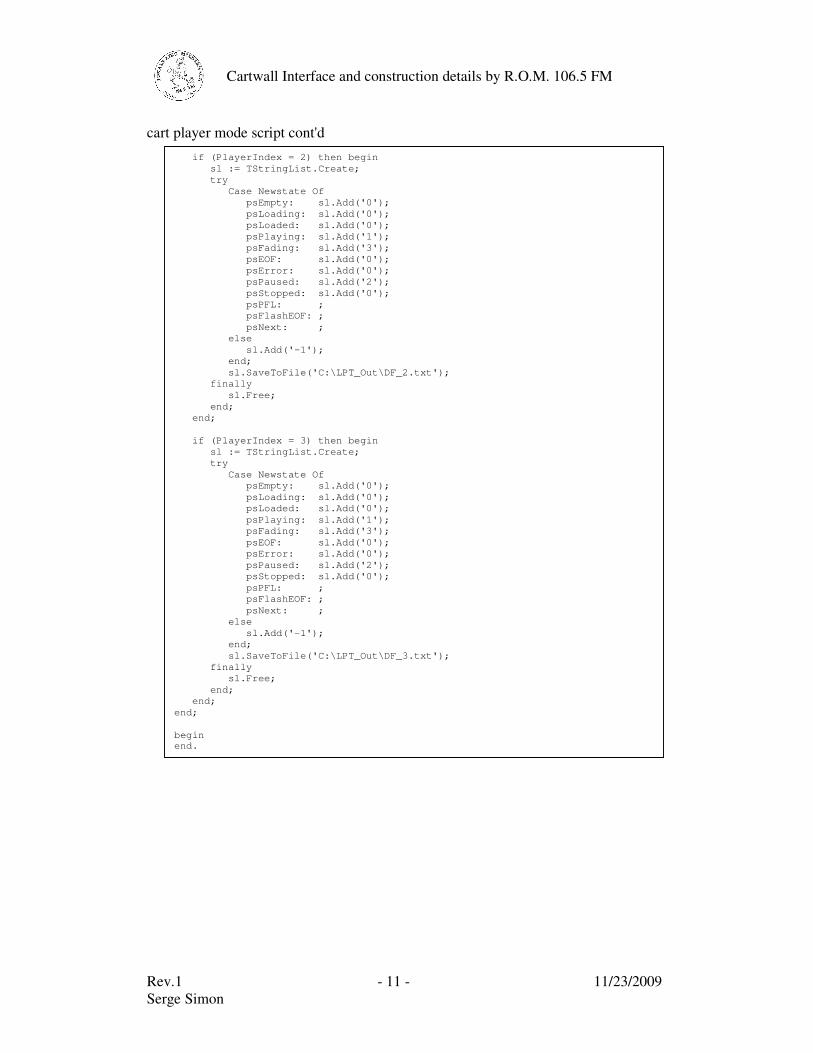
cart player mode script cont'd
if (PlayerIndex = 2) then begin sl := TStringList.Create; try Case Newstate Of psEmpty: sl.Add('0'); psLoading: sl.Add('0'); psLoaded: sl.Add('0'); psPlaying: sl.Add('1'); psFading: sl.Add('3'); psEOF: sl.Add('0'); psError: sl.Add('0'); psPaused: sl.Add('2'); psStopped: sl.Add('0'); psPFL: ; psFlashEOF: ; psNext: ; else sl.Add('-1'); end; sl.SaveToFile('C:\LPT_Out\DF_2.txt'); finally sl.Free; end; end; if (PlayerIndex = 3) then begin sl := TStringList.Create; try Case Newstate Of psEmpty: sl.Add('0'); psLoading: sl.Add('0'); psLoaded: sl.Add('0'); psPlaying: sl.Add('1'); psFading: sl.Add('3'); psEOF: sl.Add('0'); psError: sl.Add('0'); psPaused: sl.Add('2'); psStopped: sl.Add('0'); psPFL: ; psFlashEOF: ; psNext: ; else sl.Add('-1'); end; sl.SaveToFile('C:\LPT_Out\DF_3.txt'); finally sl.Free; end; end; end; begin end.
Rev.1 - 12 - 11/23/2009 Serge Simon
Cartwall Interface and construction details by R.O.M. 106.5 FM
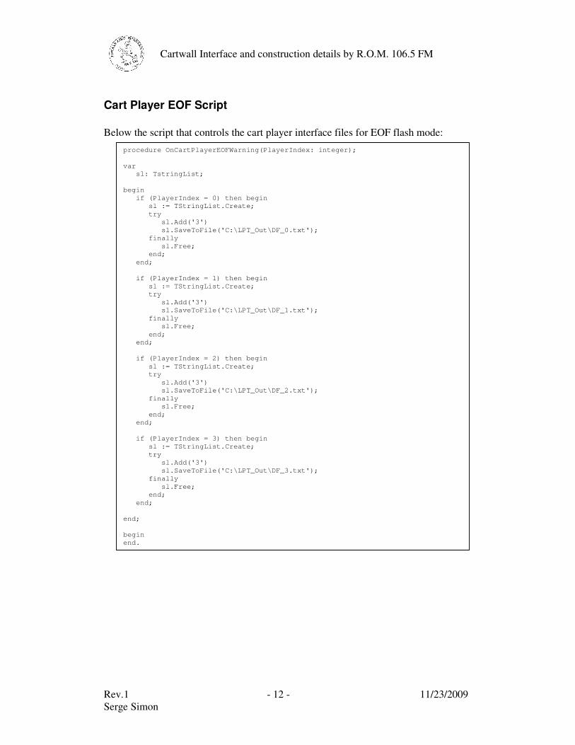
Cart Player EOF Script Below the script that controls the cart player interface files for EOF flash mode:
procedure OnCartPlayerEOFWarning(PlayerIndex: integer); var sl: TstringList; begin if (PlayerIndex = 0) then begin sl := TStringList.Create; try sl.Add('3') sl.SaveToFile('C:\LPT_Out\DF_0.txt'); finally sl.Free; end; end; if (PlayerIndex = 1) then begin sl := TStringList.Create; try sl.Add('3') sl.SaveToFile('C:\LPT_Out\DF_1.txt'); finally sl.Free; end; end; if (PlayerIndex = 2) then begin sl := TStringList.Create; try sl.Add('3') sl.SaveToFile('C:\LPT_Out\DF_2.txt'); finally sl.Free; end; end; if (PlayerIndex = 3) then begin sl := TStringList.Create; try sl.Add('3') sl.SaveToFile('C:\LPT_Out\DF_3.txt'); finally sl.Free; end; end; end; begin end.
Rev.1 - 13 - 11/23/2009 Serge Simon
Cartwall Interface and construction details by R.O.M. 106.5 FM
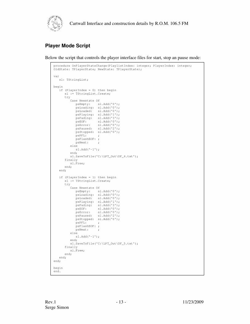
Player Mode Script Below the script that controls the player interface files for start, stop an pause mode:
procedure OnPlayerStateChange(PlaylistIndex: integer; PlayerIndex: integer; OldState: TPlayerState; NewState: TPlayerState); var sl: TStringList; begin if (PlayerIndex = 0) then begin sl := TStringList.Create; try Case Newstate Of psEmpty: sl.Add('0'); psLoading: sl.Add('0'); psLoaded: sl.Add('0'); psPlaying: sl.Add('1'); psFading: sl.Add('3'); psEOF: sl.Add('0'); psError: sl.Add('0'); psPaused: sl.Add('2'); psStopped: sl.Add('0'); psPFL: ; psFlashEOF: ; psNext: ; else sl.Add('-1'); end; sl.SaveToFile('C:\LPT_Out\DF_4.txt'); finally sl.Free; end; end; if (PlayerIndex = 1) then begin sl := TStringList.Create; try Case Newstate Of psEmpty: sl.Add('0'); psLoading: sl.Add('0'); psLoaded: sl.Add('0'); psPlaying: sl.Add('1'); psFading: sl.Add('3'); psEOF: sl.Add('0'); psError: sl.Add('0'); psPaused: sl.Add('2'); psStopped: sl.Add('0'); psPFL: ; psFlashEOF: ; psNext: ; else sl.Add('-1'); end; sl.SaveToFile('C:\LPT_Out\DF_5.txt'); finally sl.Free; end; end; end; begin end.
Rev.1 - 14 - 11/23/2009 Serge Simon
Cartwall Interface and construction details by R.O.M. 106.5 FM
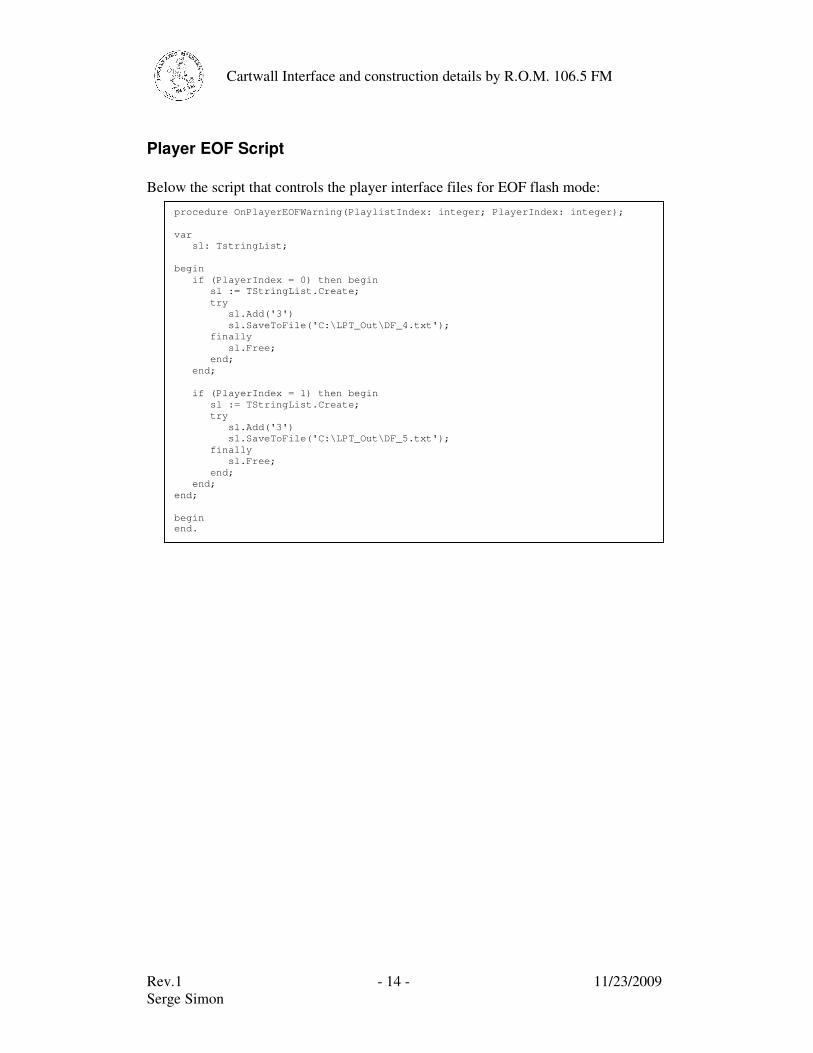
Player EOF Script Below the script that controls the player interface files for EOF flash mode:
procedure OnPlayerEOFWarning(PlaylistIndex: integer; PlayerIndex: integer); var sl: TstringList; begin if (PlayerIndex = 0) then begin sl := TStringList.Create; try sl.Add('3') sl.SaveToFile('C:\LPT_Out\DF_4.txt'); finally sl.Free; end; end; if (PlayerIndex = 1) then begin sl := TStringList.Create; try sl.Add('3') sl.SaveToFile('C:\LPT_Out\DF_5.txt'); finally sl.Free; end; end; end; begin end.
Rev.1 - 15 - 11/23/2009 Serge Simon
Cartwall Interface and construction details by R.O.M. 106.5 FM
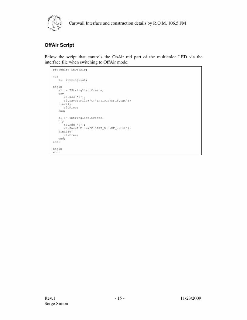
OffAir Script Below the script that controls the OnAir red part of the multicolor LED via the interface file when switching to OffAir mode:
procedure OnOffAir; var sl: TStringList; begin sl := TStringList.Create; try sl.Add('2'); sl.SaveToFile('C:\LPT_Out\DF_6.txt'); finally sl.Free; end; sl := TStringList.Create; try sl.Add('0'); sl.SaveToFile('C:\LPT_Out\DF_7.txt'); finally sl.Free; end; end; begin end.
Rev.1 - 16 - 11/23/2009 Serge Simon
Cartwall Interface and construction details by R.O.M. 106.5 FM
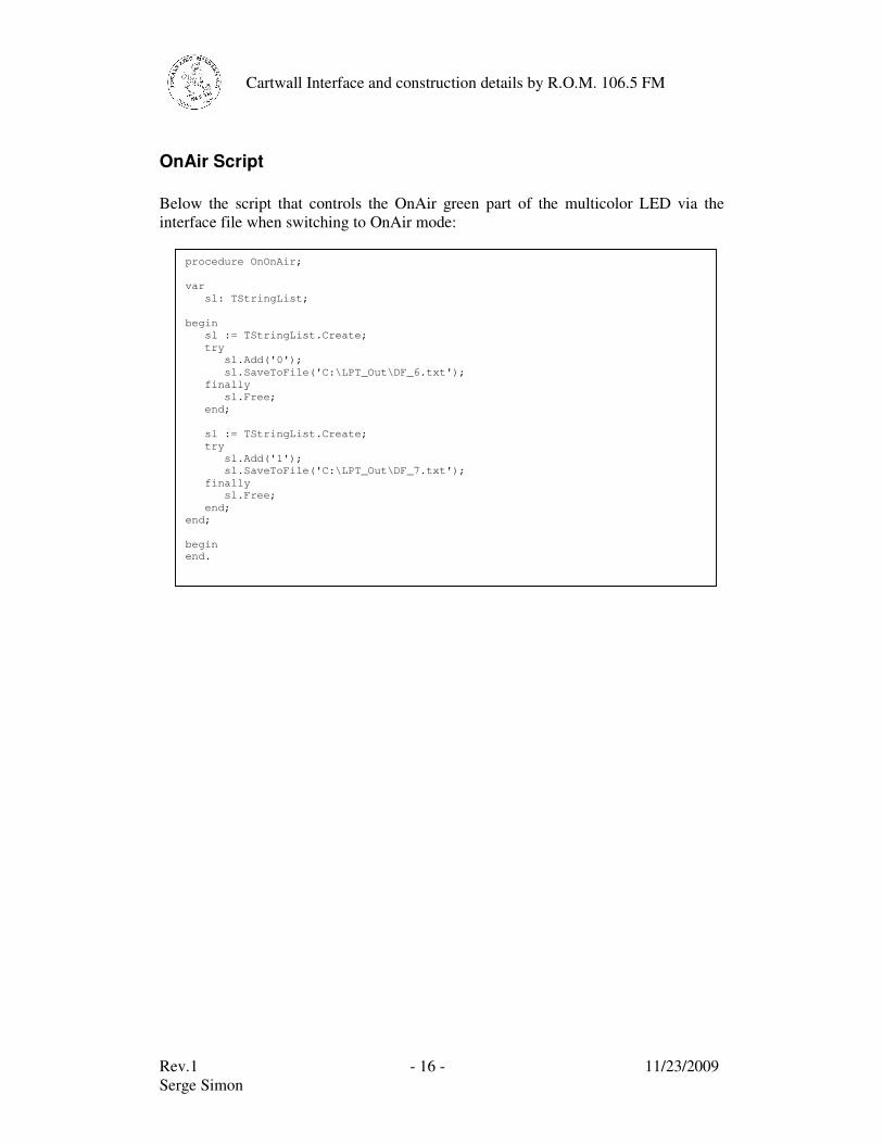
OnAir Script Below the script that controls the OnAir green part of the multicolor LED via the interface file when switching to OnAir mode:
procedure OnOnAir; var sl: TStringList; begin sl := TStringList.Create; try sl.Add('0'); sl.SaveToFile('C:\LPT_Out\DF_6.txt'); finally sl.Free; end; sl := TStringList.Create; try sl.Add('1'); sl.SaveToFile('C:\LPT_Out\DF_7.txt'); finally sl.Free; end; end; begin end.
Rev.1 - 17 - 11/23/2009 Serge Simon
Cartwall Interface and construction details by R.O.M. 106.5 FM
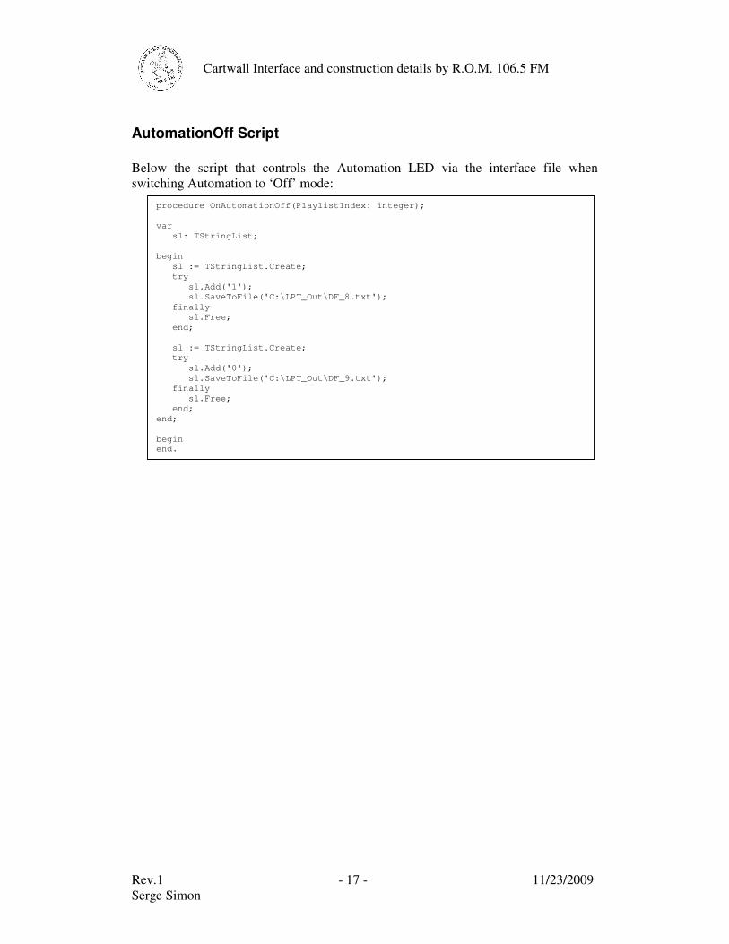
AutomationOff Script Below the script that controls the Automation LED via the interface file when switching Automation to ‘Off’ mode:
procedure OnAutomationOff(PlaylistIndex: integer); var sl: TStringList; begin sl := TStringList.Create; try sl.Add('1'); sl.SaveToFile('C:\LPT_Out\DF_8.txt'); finally sl.Free; end; sl := TStringList.Create; try sl.Add('0'); sl.SaveToFile('C:\LPT_Out\DF_9.txt'); finally sl.Free; end; end; begin end.

Rev.1 - 18 - 11/23/2009 Serge Simon
Cartwall Interface and construction details by R.O.M. 106.5 FM
AutomationOn Script Below the script that controls the Automation LED via the interface file when switching Automation to ‘On’ mode:
procedure OnAutomationOn(PlaylistIndex: integer); var sl: TStringList; begin sl := TStringList.Create; try sl.Add('0'); sl.SaveToFile('C:\LPT_Out\DF_8.txt'); finally sl.Free; end; sl := TStringList.Create; try sl.Add('1'); sl.SaveToFile('C:\LPT_Out\DF_9.txt'); finally sl.Free; end; end; begin end.
Rev.1 - 19 - 11/23/2009 Serge Simon
Cartwall Interface and construction details by R.O.M. 106.5 FM
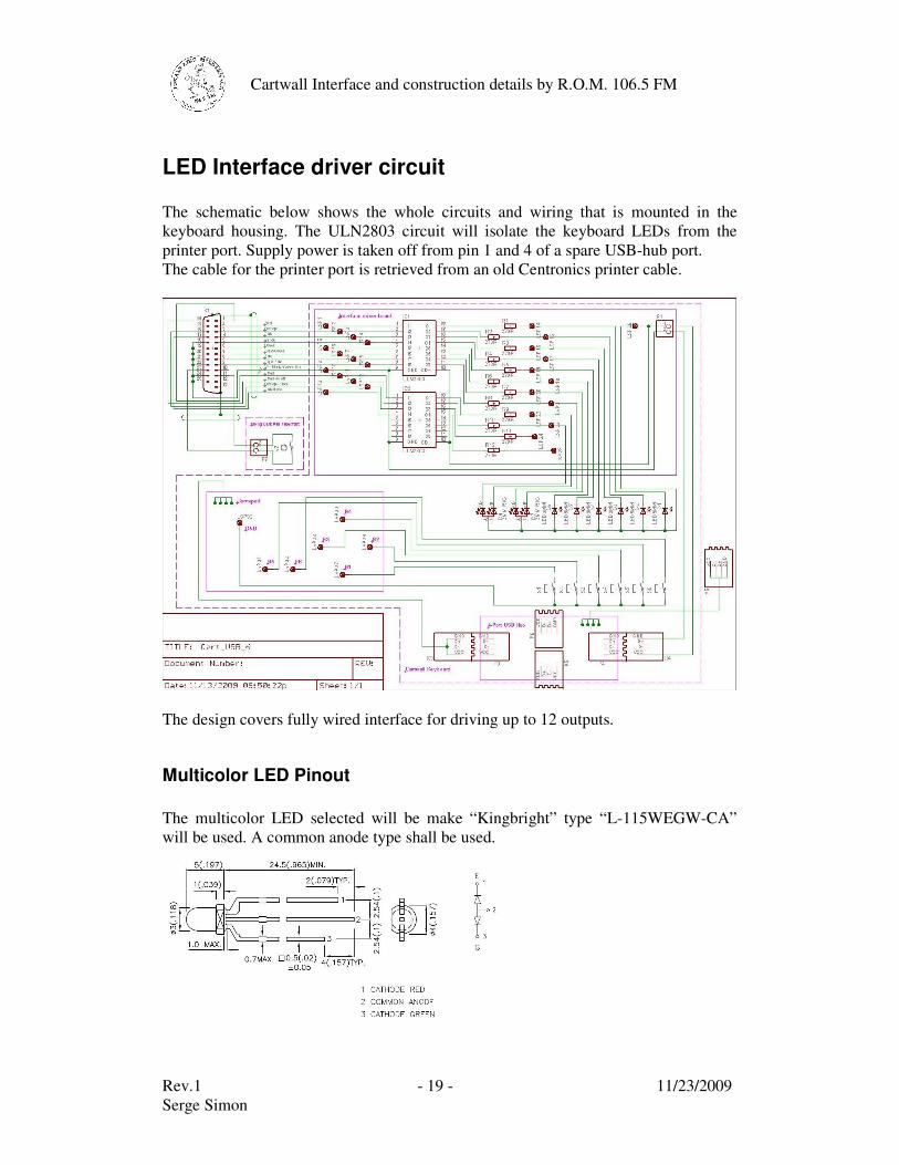
LED Interface driver circuit The schematic below shows the whole circuits and wiring that is mounted in the keyboard housing. The ULN2803 circuit will isolate the keyboard LEDs from the printer port. Supply power is taken off from pin 1 and 4 of a spare USB-hub port. The cable for the printer port is retrieved from an old Centronics printer cable.
The design covers fully wired interface for driving up to 12 outputs.
Multicolor LED Pinout The multicolor LED selected will be make “Kingbright” type “L-115WEGW-CA” will be used. A common anode type shall be used.
Rev.1 - 20 - 11/23/2009 Serge Simon
Cartwall Interface and construction details by R.O.M. 106.5 FM
Pushbuttons Getting illuminated pushbuttons at a reasonable price is almost impossible. Furthermore most of these pushbuttons require square cutouts, contain regular bulbs or have deep bodies that would require large housings. So it was decided to go with Schurter MCS18 tactile switches that will be modified slightly in order to accommodate an LED indicator. Here below we see the unmodified and modified switches.
The leftmost is the original switch, next to it we see a drilled one, in the middle we see one with an LED installed and with removed bezel. The yellow and blue switch on the right side show what they will look like when modified. The upper row show the backside of the switches. Later a foil with caption will be put onto the switch and clamped with the bezel. So in order to modify the switches, first drill a 1.5 mm hole. Then with a 3 mm wood drill slowly, very slowly with only slight pressure drill through the foil, then through the body of the switch. It is indespensable to use a wood drill as this one is flat and pushes the foil down. A standard drill will tear the foil off the switch due to its cone. So don't even try it…
Rev.1 - 21 - 11/23/2009 Serge Simon
Cartwall Interface and construction details by R.O.M. 106.5 FM
Ok, the plastic of the body will be "shaped" by means of a cutter to allow the LED to get fully through the switch. Then the LED will be glued with a drop of preferably "Faller Expert" glue. As the LED exactly sits in the middle of the o-ring groove, the switch will no more comply with IP6x standard, but who cares… we won't use the keyboard under the shower anyhow.
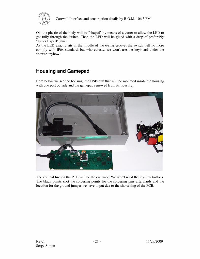
Housing and Gamepad Here below we see the housing, the USB-hub that will be mounted inside the housing with one port outside and the gamepad removed from its housing.
The vertical line on the PCB will be the cut trace. We won't need the joystick buttons. The black points shot the soldering points for the soldering pins afterwards and the location for the ground jumper we have to put due to the shortening of the PCB.
Rev.1 - 22 - 11/23/2009 Serge Simon
Cartwall Interface and construction details by R.O.M. 106.5 FM
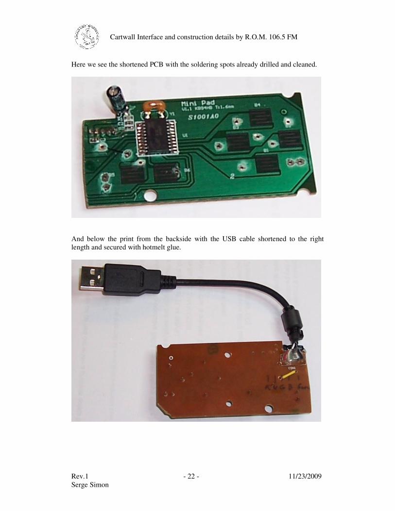
Here we see the shortened PCB with the soldering spots already drilled and cleaned.
And below the print from the backside with the USB cable shortened to the right length and secured with hotmelt glue.
Rev.1 - 23 - 11/23/2009 Serge Simon
Cartwall Interface and construction details by R.O.M. 106.5 FM
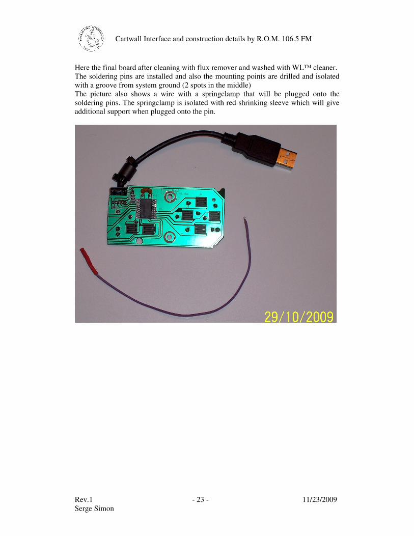
Here the final board after cleaning with flux remover and washed with WL™ cleaner. The soldering pins are installed and also the mounting points are drilled and isolated with a groove from system ground (2 spots in the middle) The picture also shows a wire with a springclamp that will be plugged onto the soldering pins. The springclamp is isolated with red shrinking sleeve which will give additional support when plugged onto the pin.
Rev.1 - 24 - 11/23/2009 Serge Simon
Cartwall Interface and construction details by R.O.M. 106.5 FM
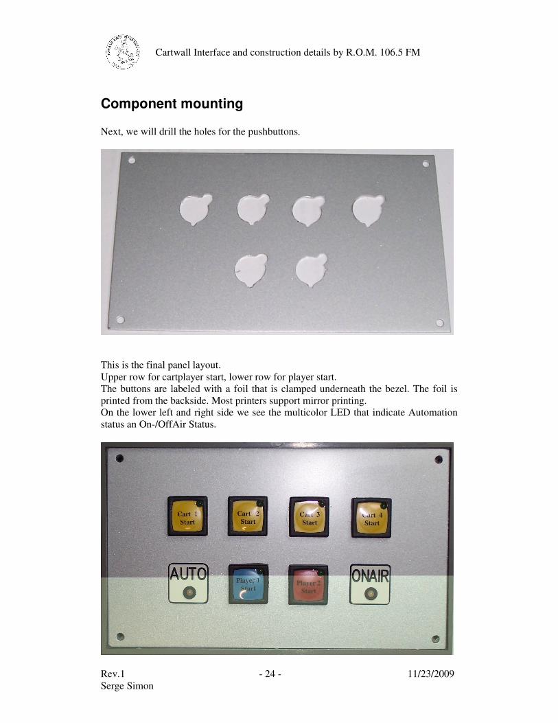
Component mounting Next, we will drill the holes for the pushbuttons.
This is the final panel layout. Upper row for cartplayer start, lower row for player start. The buttons are labeled with a foil that is clamped underneath the bezel. The foil is printed from the backside. Most printers support mirror printing. On the lower left and right side we see the multicolor LED that indicate Automation status an On-/OffAir Status.
Rev.1 - 25 - 11/23/2009 Serge Simon
Cartwall Interface and construction details by R.O.M. 106.5 FM
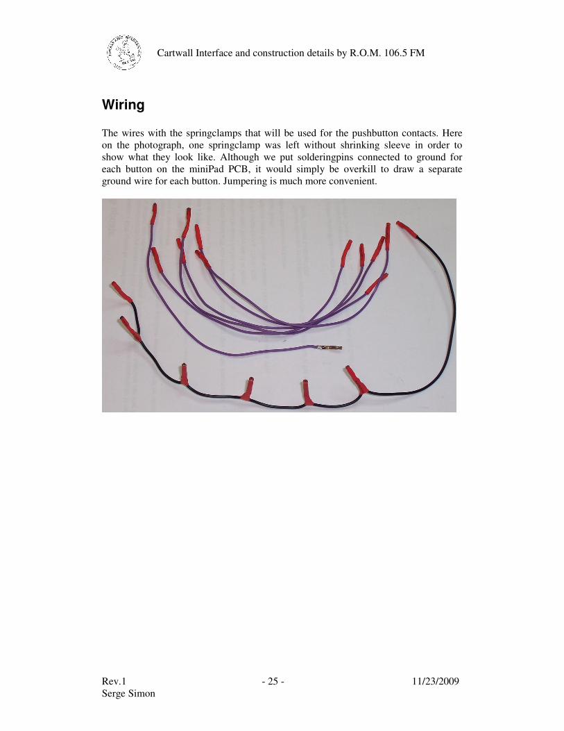
Wiring The wires with the springclamps that will be used for the pushbutton contacts. Here on the photograph, one springclamp was left without shrinking sleeve in order to show what they look like. Although we put solderingpins connected to ground for each button on the miniPad PCB, it would simply be overkill to draw a separate ground wire for each button. Jumpering is much more convenient.
Rev.1 - 26 - 11/23/2009 Serge Simon
Cartwall Interface and construction details by R.O.M. 106.5 FM
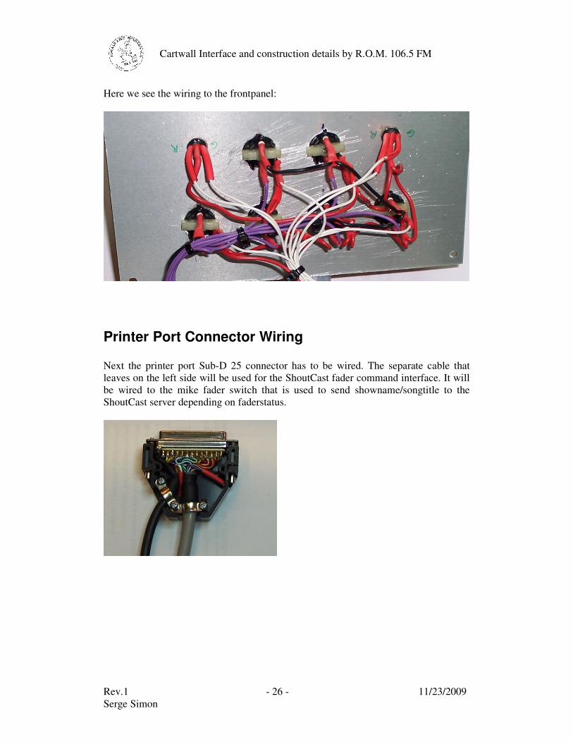
Here we see the wiring to the frontpanel:
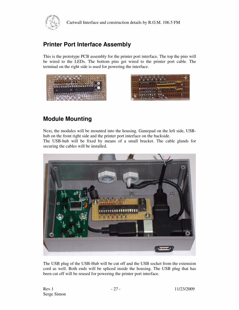
Printer Port Connector Wiring Next the printer port Sub-D 25 connector has to be wired. The separate cable that leaves on the left side will be used for the ShoutCast fader command interface. It will be wired to the mike fader switch that is used to send showname/songtitle to the ShoutCast server depending on faderstatus.
Rev.1 - 27 - 11/23/2009 Serge Simon
Cartwall Interface and construction details by R.O.M. 106.5 FM
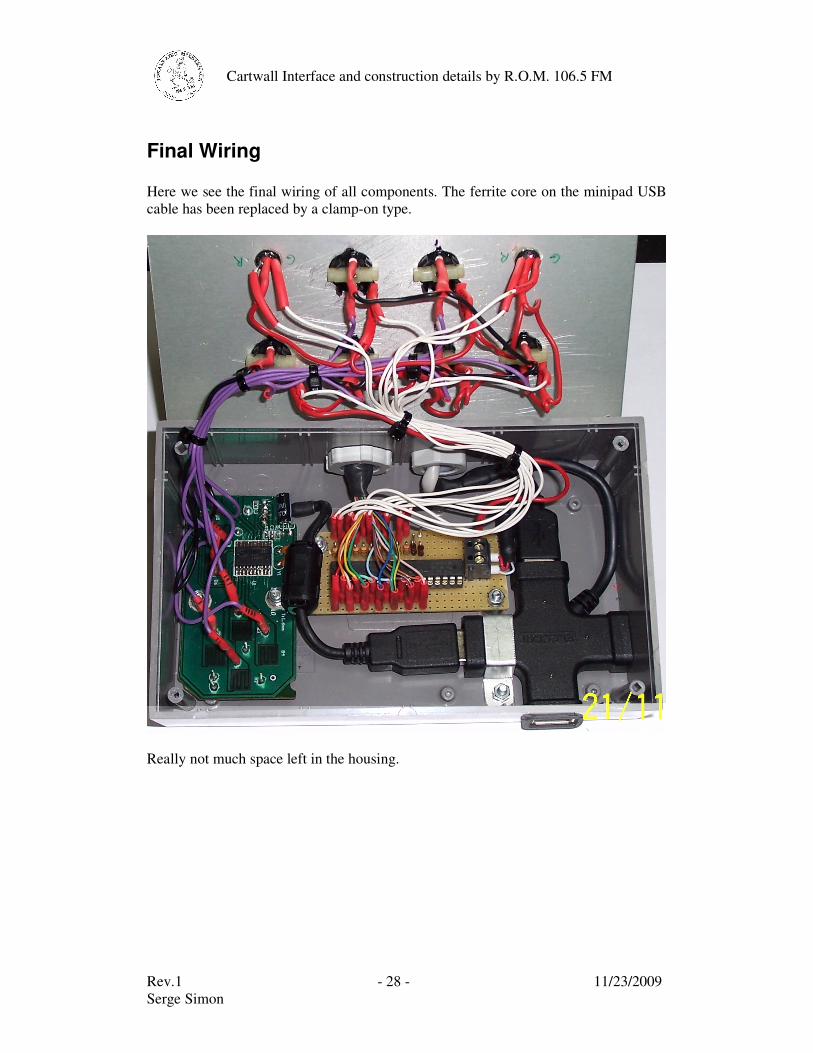
Printer Port Interface Assembly This is the prototype PCB assembly for the printer port interface. The top the pins will be wired to the LEDs. The bottom pins get wired to the printer port cable. The terminal on the right side is used for powering the interface.
Module Mounting Next, the modules will be mounted into the housing. Gamepad on the left side, USB-hub on the front right side and the printer port interface on the backside. The USB-hub will be fixed by means of a small bracket. The cable glands for securing the cables will be installed.
The USB plug of the USB-Hub will be cut off and the USB socket from the extension cord as well. Both ends will be spliced inside the housing. The USB plug that has been cut off will be reused for powering the printer port interface.
Rev.1 - 28 - 11/23/2009 Serge Simon
Cartwall Interface and construction details by R.O.M. 106.5 FM
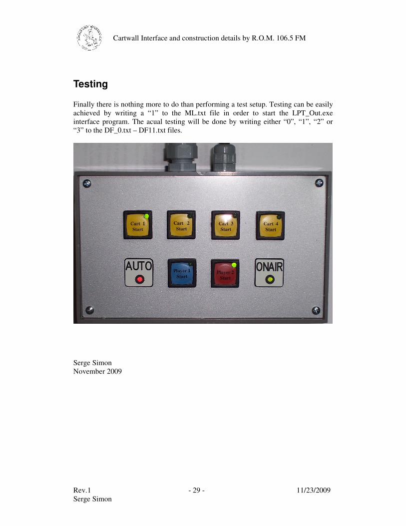
Final Wiring Here we see the final wiring of all components. The ferrite core on the minipad USB cable has been replaced by a clamp-on type.
Really not much space left in the housing.
Rev.1 - 29 - 11/23/2009 Serge Simon
Cartwall Interface and construction details by R.O.M. 106.5 FM
Testing Finally there is nothing more to do than performing a test setup. Testing can be easily achieved by writing a “1” to the ML.txt file in order to start the LPT_Out.exe interface program. The acual testing will be done by writing either “0”, “1”, “2” or “3” to the DF_0.txt – DF11.txt files.
Serge Simon November 2009


![Autdev Interface [Autorship + Webdevelopment + Interface]](https://img.pdfslide.us/doc/110x75/568bd8ee1a28ab2034a52641/autdev-interface-autorship-webdevelopment-interface.jpg)