Embed Size (px)
Citation preview
A-92
Components
Cartridge HeatersApplication & InstallationRecommendationsApplications
Application at High Watt Densities —Type CIR cartridge heaters are designed andmanufactured to provide watt densitycapabilities second to none. To obtain best lifeat the highest watt densities allowed per CurveG-235 in the Application Guidelines, closeattention to application details is suggested.
A. For closest fit and best heat transfer, holesshould be drilled and reamed, rather thanjust drilled to final diameter with a general-purpose drill.
B. The sensor for the temperature controlshould be placed between the workingsurface of the part and the heaters. Thetemperature of the part approximately 1/2"away from the heaters is used in selectingmaximum allowable watt density from thegraph.
C. Control of power is an important consider-ation in high watt density applications.On/Off control is frequently utilized, but itcan cause wide excursions in thetemperature of the heater and workingparts. SCR power controls are valuable inextending the life of high watt densityheaters, since they effectively eliminateon-off cycling.
Application at Medium Watt Densities —Curve G-235 in the Application Guidelinesshows maximum allowable watt density forvarious fits and operating temperatures. Thevast majority of applications do not requiremaximum W/In2, however. Use a watt densityonly as high as you need. Take advantage ofthe safety margin provided by using ratingsless than the maximum allowed. Select andspace heaters for most even heat patternrather than for highest possible wattage perheater.
At medium watt densities, general purposedrills are usually adequate for drilling holes.Typically, these result in holes 0.003 to 0.008"over the normal size of the drill, resulting infits of 0.01 to 0.015". Of course, the tightest fitis desirable from a heat transfer standpoint,but somewhat looser fits aid in installing andremoving cartridge heaters, especially longones. Holes drilled completely through thepart are recommended to facilitate removal ofthe heater. After drilling, clean or degrease thepart to remove cutting lubricants.
Operation in Vacuum — When heaters areoperated in a block which is in a vacuum, theinside of the holes should be pre-oxidized to
improve emissivity. Substantial reductions inmaximum allowable watt density are usuallynecessary for vacuum operation. Wherepossible, the installation should be designedso that the lead end of the heater is outside thevacuum. When the lead end of the heater isinside the vacuum, a voltage of 120 volts orless is recommended. On an unsealed heater,outgassing may be expected.
Operation in Square Grooves — Round typeCIR cartridge heaters may be installed insquare or v-shaped grooves if this provesconvenient. The inside of the groove should betreated to improve its emissivity (by oxidizingor anodizing). Allowable W/In2 can beestimated by using the 0.05" fit line in thegraph, providing that the square is approxi-mately the same width as the nominaldiameter of the heater.
Operation on 480V — Chromalox type CIRcartridge heaters 5/8" diameter and larger canbe operated on 480 volts. One approach is totake two stock 240 volt heaters and connectthem in series on 480 volts. Another is toorder specially rated 480 volt cartridgeheaters. Check with your Local ChromaloxSales office for recommendations.
Because of higher voltage stresses inside theheater, lower maximum watt densities areallowable in 480 volt applications, either withtwo 240 volt heaters in series or with speciallyrated 480 volt units. To determine maximumallowable watt density at 480 volts, enterCurve G-235 with an operating temperaturevalue which is 200°F higher than the actualoperating temperature. A maximum operatingtemperature of 1000°F is suggested.
Testing Recommendations
Testing Recommendations — Testing undersimulated operating conditions is suggestedwhen equipment manufacturers design newproducts. Cartridge heaters of the appropriatephysical size are operated on a variabletransformer until the heat output is at theproper level. Then, voltage and currentmeasurements are taken and required wattagerating is calculated. Heaters of the correctwattage rating are then ordered for thedesigned product.
Installation Recommendations
1. On moving machinery, anchor the leadssecurely. As little movement as possibleshould be allowed close to where the leadsemerge from the heater. A loop in the lead
wire will frequently extend lead life. Ifapplication conditions result in continuallead flexing, terminate the cartridge heaterleads at a terminal block which moves withthe heated assembly. Flexing is transferredto the extension leads which can beeconomically replaced.
2. For rapidly vibrating equipment, employthe terminal block described above. Keepleads from heater to block short and wellsupported to prevent lead movement dueto vibration.
3. Protect leads from spray, oil and abrasion.Contaminating liquids and vapors canenter unsealed cartridge heaters and causeinsulation breakdown.
4. Avoid tape on leads where they emergefrom the cartridge heater. The adhesive onsome tapes can enter the heater and turnto carbon which is electrically conductive.Where glass tape cannot be avoided, atape with a silicone based adhesive issuggested.
5. Design the installation so that the leads arein an ambient temperature which doesn'texceed the rating on the lead insulation(842°F for standard leads). Wheretemperatures require it, use nickel ornickel-plated copper wire withfluoropolymer insulation, siliconeimpregnated Fiberglas® or Rockbestos®
insulation to extend leads.
6. Graphite and other lubricants to helpinsert the cartridge heater into the holeare generally not recommended. These areelectrically conductive and can get on thelead end of the heater unless extra care istaken. Use Chromalox heat transfer andrelease coating.
7. As operating temperatures rise, thermalinsulation on the heated part becomesmore desirable to conserve heat. Thermalinsulation results in lower wattagerequirements and therefore lower wattdensity on the heaters. Other benefits aremore even work temperatures and greateroperator safety and comfort.
8. Leads must not extend into the holecontaining the cartridge heater. Generally,the lead end of the heater sheath should beflush with the surface of hole or extendedby 1/16 inch.
A-092 App Install.P65 9/18/02, 3:42 PM1

A-93
Components
Protective Spring Providesa Flexible Strain Relief
to Leadwire
Cartridge HeatersModifications & Options
Mica Fiberglas® 300V Standard 842 450Insulation 600VFluoropolymer 300V 392 200
600V
Description Volts (°F) (°C)
OperatingTemperature
Leadwire Types
Air Set Cement Standard 1000 538Epoxy Seal 194 90Fluoropolymer Seal 392 200RTV Seal 284 140
392 200Hermetic Seal 1000 538
Description (°F) (°C)
OperatingTemperature
End Seal Temperature Limits
Epoxy Epoxy seal available on aboveleads by voiding end of sheathand filling with epoxy to provide amoisture barrier.
Fluoro- A swaged-in seal that providespolymer additional moisture resistance.RTV For applications where a moisture
barrier is required.Hermetic Ceramic-to-metal seal is good for
element temperatures up to1000°F. Specify heater lengthbeyond the seal. Metal portion ofthe seal overlaps the heater sheathby 3/16".
Type Description/Application
Seal Options
Modifications & Options
Cartridge heaters can be easily specified tomeet the demands of special applications.Simply select from a variety of standardoptions and features to customize the heaterto your specific needs. For customizedengineering or alternative options, contactyour Chromalox sales representative for fastturnaround on your specifications.
• Leadwire Types
• End Seal Options
• Lead Options
• Mounting Options
• Built-In Thermocouple
End Seal Options
Hermetic Seal
Ceramic-to-metal seal is good for elementtemperatures up to 1000°F. Specify heaterlength beyond the seal. Metal portion of theseal overlaps the heater sheath by 3/16”. Forwashdown conditions.
Hermetic Seal Code 8C
Lead Options
Right Angle Flexible Leads
Heat Shrink Insulation (100°C)
Code 14C
Strain Relief
Strain Relief supports leads to reducebending, crimping and breakage.
Code 19C
Protective Spring
Available in both straight and right angleconfigurations, the Protective Spring givesstrong, yet flexible leadwire protection frombending, fatigue and flexing.
Flexible Stainless Steel Conduit
Flexible Stainless Steel Conduit providesleadwire protection from abrasion and sharpedges, and facilitates easier handling in harshenvironments. Available in both straight andright angle configurations.
Right AngleCode 15C - StandardCode 16C - Moisture Resistant
Flexible Stainless Steel Conduitfor Abrasion Protection
StraightCode 4C - StandardCode 5C - Moisture Resistant
Right AngleCode 18C
Straight Code 3C
Heat Shrink Insulation(100°C)
Heat ShrinkInsulation(100°C)
Protective Spring
Lead Options (cont’d.)
CART
RIDG
E
A-093.P65 9/18/02, 3:43 PM1
A-94
Components
Threaded Post Terminals
Post Terminals provide a strong, secureconnection to buss bars or ring/fork connec-tors. Available only on 5/8 and 3/4” diameterheaters.
Metal Braid ProtectsLeads from Abrasiveand Sharp Surfaces
Cartridge HeatersModifications & Options (cont’d.)
Lead Options (cont’d.)
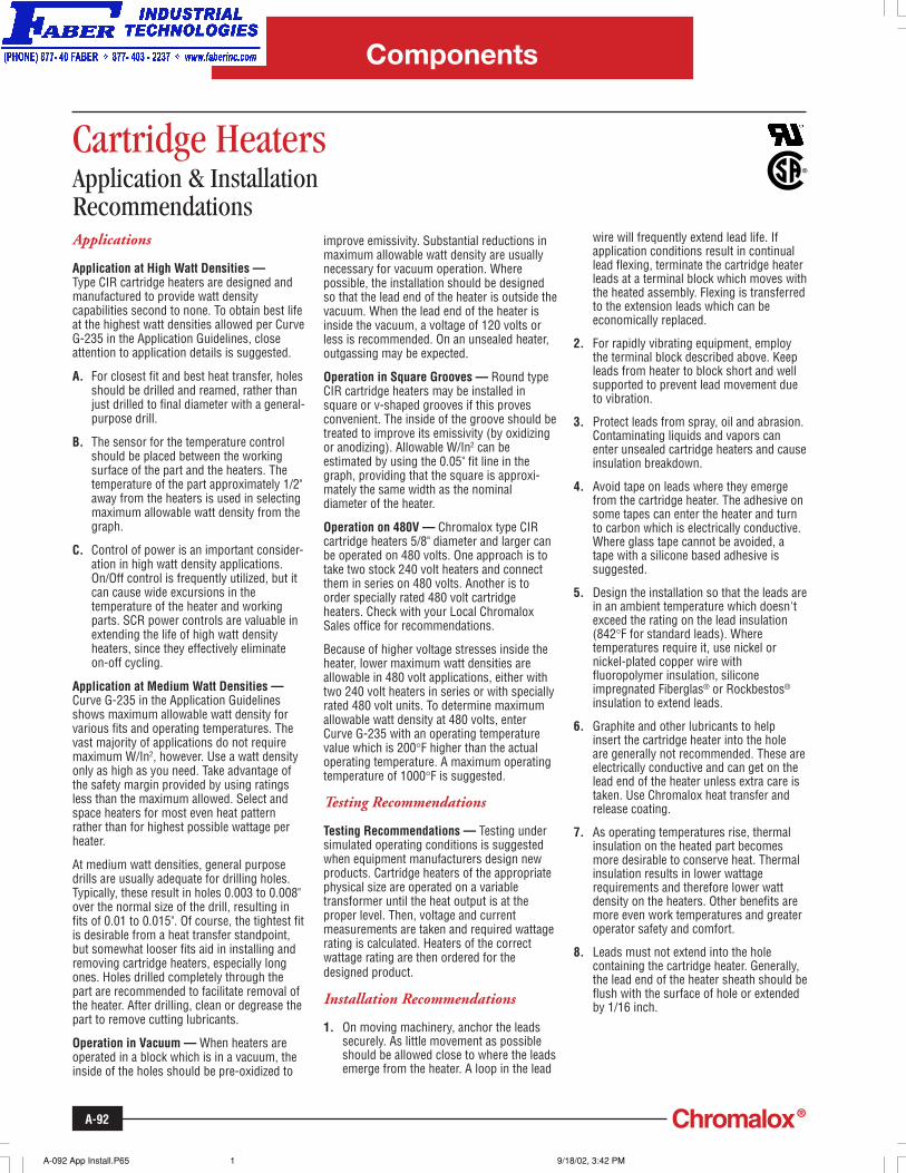
Metal Braid
Stainless Steel metal braid protects leadwirefrom abrasion and sharp edges, yet maintainsflexibility and ease of installation. Metal braidis available in both straight and right angleconfigurations.
Code 17C Right Angle
Heat ShrinkInsulation(100°C)
Code 13C Straight
Heat ShrinkInsulation
(100°F)
Ceramic Beads
Ceramic Bead insulation can be specified toprotect leadwires from high ambient tempera-tures up to 1200°F (649°C). To order, specifyceramic beads length and additional leadlength.
Code 12C
InsulatingBeads
LeadwireCrimpedto RetainInsulationBeads
Code 20C
Mounting Options
Threaded Fittings
Threaded fittings allow the heater to be easilyinstalled into a threaded hole for immersionapplications. Available with single or doublethreaded fittings. The fitting overlaps thecartridge heater sheath by 1/4". Specify“brass” or “stainless steel” threaded fitting.
Threaded Fitting Sizes
Code 9CS Single End
Code 9CD Double End
1/4 1/8 - 27 7/163/8 1/4 - 18 9/161/2 3/8 - 14 11/165/8 1/2 - 14 7/83/4 3/4 - 14 1-1/16
Nom. Heater NPT Size Hex SizeDiameter (In.) (In.) (In.)
Mounting Flange
The mounting flange option allows for easymounting and specific positioning of theheater within an application.
Code 10C
1/8" Thick StainlessSteel Mounting Flange
Wire Pull
The Wire Pull assists in heater removal.
Code 11C
A-094.P65 9/18/02, 3:44 PM1
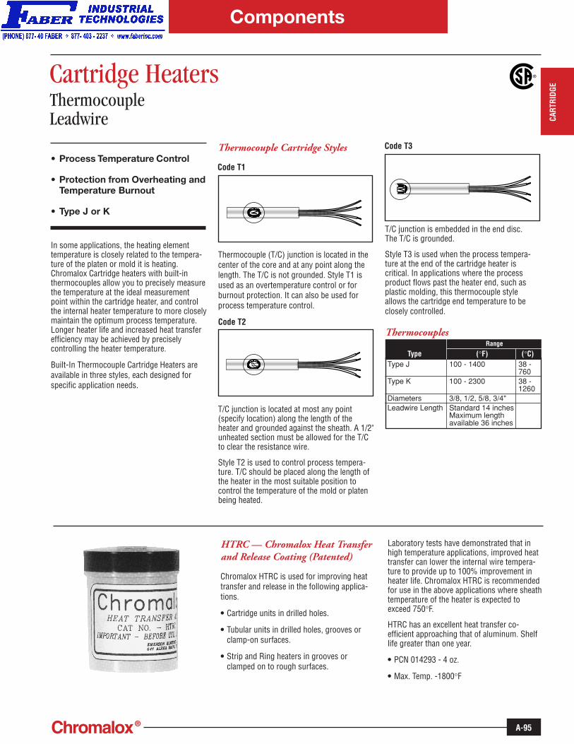
A-95
Components
Cartridge HeatersThermocoupleLeadwire
• Process Temperature Control
• Protection from Overheating andTemperature Burnout
• Type J or K
In some applications, the heating elementtemperature is closely related to the tempera-ture of the platen or mold it is heating.Chromalox Cartridge heaters with built-inthermocouples allow you to precisely measurethe temperature at the ideal measurementpoint within the cartridge heater, and controlthe internal heater temperature to more closelymaintain the optimum process temperature.Longer heater life and increased heat transferefficiency may be achieved by preciselycontrolling the heater temperature.
Built-In Thermocouple Cartridge Heaters areavailable in three styles, each designed forspecific application needs.
Thermocouple Cartridge Styles
Code T1
Thermocouple (T/C) junction is located in thecenter of the core and at any point along thelength. The T/C is not grounded. Style T1 isused as an overtemperature control or forburnout protection. It can also be used forprocess temperature control.
Code T2
Code T3
T/C junction is located at most any point(specify location) along the length of theheater and grounded against the sheath. A 1/2"unheated section must be allowed for the T/Cto clear the resistance wire.
Style T2 is used to control process tempera-ture. T/C should be placed along the length ofthe heater in the most suitable position tocontrol the temperature of the mold or platenbeing heated.
T/C junction is embedded in the end disc.The T/C is grounded.
Style T3 is used when the process tempera-ture at the end of the cartridge heater iscritical. In applications where the processproduct flows past the heater end, such asplastic molding, this thermocouple styleallows the cartridge end temperature to beclosely controlled.
HTRC — Chromalox Heat Transferand Release Coating (Patented)
Chromalox HTRC is used for improving heattransfer and release in the following applica-tions.
• Cartridge units in drilled holes.
• Tubular units in drilled holes, grooves orclamp-on surfaces.
• Strip and Ring heaters in grooves orclamped on to rough surfaces.
Laboratory tests have demonstrated that inhigh temperature applications, improved heattransfer can lower the internal wire tempera-ture to provide up to 100% improvement inheater life. Chromalox HTRC is recommendedfor use in the above applications where sheathtemperature of the heater is expected toexceed 750°F.
HTRC has an excellent heat transfer co-efficient approaching that of aluminum. Shelflife greater than one year.
• PCN 014293 - 4 oz.
• Max. Temp. -1800°F
Type J 100 - 1400 38 -760
Type K 100 - 2300 38 -1260
Diameters 3/8, 1/2, 5/8, 3/4"Leadwire Length Standard 14 inches
Maximum lengthavailable 36 inches
Type (°F) (°C)Range
Thermocouples
CART
RIDG
E
A-095.P65 9/18/02, 3:45 PM1


![Large-scale changes in observed daily maximum and minimum ...hadobs.metoffice.gov.uk/hadghcnd/HadGHCND_paper.pdf · [2] Long-term, global-scale, gridded monthly tempera-ture data](https://img.pdfslide.us/doc/110x75/5f01c8a77e708231d4010408/large-scale-changes-in-observed-daily-maximum-and-minimum-2-long-term-global-scale.jpg)