Embed Size (px)
Citation preview
I N STR UCTION MAN UAL
OR IG I NAL I N STR UCTION S /TRAN S LATION OF OR IG I NAL I N STR UCTION S R EAD AN D U N D E R STAN D TH I S MAN UAL PR IOR TO OPE RATI NG OR
S E RVICI NG TH I S PROD UCTI B-107 R06 (09/2012)
Cartridge Duo L450 D UO, L550 D UO, L650 D UO, L750 D UO

2
Recreational Craft Directive 94/25/EECISO 8849 Marine
ISO 10133
Made in USA
INDEX - INDICE
Svenska .......................................................................................................................3English .........................................................................................................................5Deutsch .......................................................................................................................7Français .......................................................................................................................9España ...................................................................................................................... 11Italiano ...................................................................................................................... 13
Besök www.johnson-pump.com för mer information om vår världsomspännande organisation, våra godkännanden, certifieringar och lokala representanter. SPX Corporation förbehåller sig rätten att ändra design och material utan föregående avisering. Designelement, konstruktionsmaterial och dimensioner som beskrivs i denna bulletin gäller endast som information och skall alltid bekräftas skriftligt för att vara gällande.
For more information about our worldwide locations, approvals, certifications, and local representatives, please visit www.johnson-pump.com. SPX Corporation reserves the right to incorporate our latest design and material changes without notice or obligation. Design features, materials of construction and dimensional data, as described in this bulletin, are provided for your information only and should not be relied upon unless confirmed in writing.
Für weitere Informationen über unsere weltweiten Standorte, Zulassungen, Zertifizierungen und unsere Vertreter vor Ort, besuchen Sie bitte unsere Webseite: www.johnson-pump.com. Die SPX Corporation behält sich das Recht vor, die neuesten Konstruktions- und Werkstoffänderungen ohne vorherige Ankündigung und ohne Verpflichtung hierzu einfließen zu lassen. Konstruktive Ausgestaltungen, Werkstoffe sowie Maßangaben, wie sie in dieser Mitteilung beschrieben sind, sind nur zur Information. Alle Angaben sind unverbindlich, es sei denn, sie wurden schriftlich bestätigt.
Pour plus d’information sur nos succursales internationales, nos approbations, nos certifications et nos représentants locaux, veuillez consulter notre site Internet au www.johnson-pump.com. SPX Corporation se réserve le droit d’incorporer nos plus récents concepts ainsi que tout autre modification importante sans préavis ou obligation. Les éléments décoratifs, matériaux de construction et les données dimensionnelles, tels qu’énoncés dans ce communiqué, sont fournis pour votre information seulement et ne doivent pas être considérés comme officiels à moins d’avis contraire par écrit.
Para más información sobre nuestras oficinas a nivel mundial, aprobaciones, certificaciones y representantes locales, por favor visite www.johnson-pump.com. SPX Corporation se reserva el derecho de incorporar nuestro diseño más reciente y cambios materiales sin necesidad de notificación previa u obligación de ningún tipo. Características de diseño, materiales de construcción y dimensiones, tal y como están descritas en este boletín, son proporcionadas sólo con fines informativos y no deben ser usados como referencia a menos que sean confirmados por escrito.
Per ottenere maggiori informazioni sulle nostre sedi nel mondo, autorizzazioni, certificazioni, e rappresentanti locali, potete visitare il sito www.johnson-pump.com. La SPX Corporation si riserva il diritto di apportare cambiamenti ai propri design e materiali senza preavviso o vincolo. Le caratteristiche del design, i materiali di costruzione e i dati dimensionali, così come descritti nel presente bollettino, sono forniti solo per vostra informazione e non saranno oggetto di obbligazione salvo autorizzazione confermata per iscritto.
Garantie 3 ansGarantía 3 añosGaranzia 3 anni
Garanti 3 årWarranty 3 years Garantie 3 Jahren
Översättning av originalinstruktionerna
> Svenska
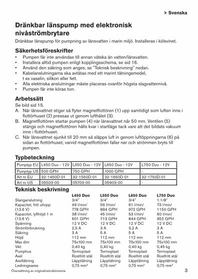
Teknisk beskrivning L450 Duo L550 Duo L650 Duo L750 Duo Slanganslutning 3/4" 3/4" 3/4" 1.1/8"Kapacitet, fritt utlopp 49 l/min/ 56 l/min/ 61 l/min/ 73 l/min/ (13.6 V) 778 GPH 884 GPH 972 GPH 1150 GPH Kapacitet, lyfthöjd 1 m 38 l/min/ 45 l/min/ 53 l/min/ 60 l/min/ (13.6 V) 601 GPH 713 GPH 844 GPH 952 GPH Spänning 12 V DC 12 V DC 12 V DC 12 V DC Strömförbrukning 2,5 A 3 A 3,2 A 3 A Säkring 3 A 5 A 5 A 5 AHöjd 112 mm 112 mm 112 mm 112 mm Max dim 75x100 mm 75x100 mm 75x100 mm 75x100 mm Vikt 0,40 kg 0,40 kg 0,40 kg 0,45 kg Pumphus Termoplast Termoplast Termoplast Termoplast Axel Rostfritt stål Rostfritt stål Rostfritt stål Rostfritt stålAxeltätning Läpptätning Läpptätning Läpptätning Läpptätning Ledningsarea 0,75 mm2 0,75 mm2 0,75 mm2 0,75 mm2
Dränkbar länspump med elektronisk nivåströmbrytareDränkbar länspump för pumpning av länsvatten i marin miljö. Installeras i kölsvinet.
Säkerhetsföreskrifter• Pumpenfårinteanvändastillannanvätskaänvatten/länsvatten.• Installeraalltidpumpenenligtkopplingsschema,sesid16.• Använddensäkringsomanges,se"Tekniskbeskrivning"nedan.• Kabelanslutningarnaskaavtätasmedettmarinttätningsmedel, t ex vaselin, silikon eller fett.• Allaelektriskaanslutningarmåsteplacerasovanförhögstaslagvattennivå.• Pumpenfårintekörastorr.
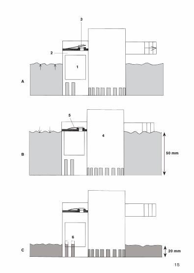
ArbetssättSe bild sid 15.A. När länsvattnet stiger så flyter magnetflottören (1) upp samtidigt som luften inne i
flottörhuset (2) pressas ut genom lufthålet (3).B. Magnetflottören startar pumpen (4) när länsvattnet når 50 mm. Ventilen (5)
stängs och magnetflottören hålls kvar i startläge tack vare att det bildats vakuum inne i flottörhuset.
C. När länsvattnet sjunkit till 20 mm så släpps luft in genom luftöppningarna (6) på sidan av flottörhuset, varvid magnetflottören faller ner och strömmen bryts till pumpen.
Typbeteckning Pumptyp EU L450 Duo - 12V L550 Duo - 12V L650 Duo - 12V L750 Duo - 12V
Pumptyp US 500 GPH 750 GPH 1000 GPH -Art nr EU 32-1450D-01 32-1550D-01 32-1650D-01 32-1750D-01Art nr US 05503-00 05703-00 05903-00 -
3
Översättning av originalinstruktionerna
> Svenska
InstallationFölj anvisningarna noggrant för att uppnå maximal effekt.1. Placera pumpen vid lägsta punkten. 2. Välj en plats där vattnet ska pumpas överbord - så högt som möjligt över vat-
tenlinjen och så nära pumpen som möjligt. Använd en 19 mm (3/4") bordgenom-föring (L750 Duo - 28 mm (1,1/8").
3. Anslut en 19 mm (3/4") (L750 Duo - 28 mm (1,1/8") bränslesäker slang från pumpens utlopp till bordgenomföringen. Undvik skarpa veck och öglor. Om nödvändigt, fäst slangen.
Obs! För att förhindra luftfickor är det viktigt att slangen inte riktas nedåt vid utloppet. Slangen ska hela tiden riktas uppåt.
Montering/demontering av motorenhetenSe sid 18 1. Lyft låshaken och vrid de två vingarna moturs och lyft ur enheten.2. Innan enheten återplaceras, kontrollera att tätningen sitter på plats. Smörj
tätningen med mineral- eller vegetabilisk olja. Placera enheten så att den passar in i skårorna på pumphuset. Pressa ned och vrid vingarna medurs. Prova om enheten är rätt placerad genom att vrida vingarna moturs utan att lyfta låshaken. Enheten ska då sitta fast ordentligt.
Tillbehör
Strömbrytarpanel 12 eller 24 V
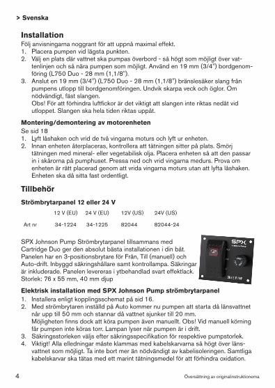
SPX Johnson Pump Strömbrytarpanel tillsammans med Cartridge Duo ger den absolut bästa installationen i din båt. Panelen har en 3-positionsbrytare för Från, Till (manuell) och Auto-drift. Inbyggd säkringshållare samt kontrollampa. Säkringar är inkluderade. Panelen levereras i ytbehandlad svart effektlack.Storlek: 76 x 55 mm, 40 mm djup
Elektrisk installation med SPX Johnson Pump strömbrytarpanel1. Installera enligt kopplingsschemat på sid 16.2. Med strömbrytaren inställd på Auto kommer nu pumpen att starta då länsvattnet
når upp till 50 mm och stannar då vattnet sjunker till 20 mm. Möjligheten finns dock att köra pumpen även manuellt. Obs! Vid manuell körning
får pumpen inte köras torr. Lampan lyser när pumpen är i drift.3. Säkringsstorleken väljs efter säkringsspecifikation för respektive pumpstorlek.4. Viktigt! Alla elledningar måste klammas med kabelskarvarna så högt över läns-
vattnet som möjligt. Ta inte bort mer än nödvändigt av kabelisoleringen. Samtliga kabelskarvar ska tätas med ett marint tätningsmedel för att förhindra oxidation.
12 V (EU) 24 V (EU) 12V (US) 24V (US)
Art nr 34-1224 34-1225 82044 82044-24
4
Original instructions
> English
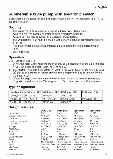
Design features L450 Duo L550 Duo L650 Duo L750 Duo Hose size 3/4" 3/4" 3/4" 1.1/8" Capacity, straight 49 l/min/ 56 l/min/ 61 l/min/ 73 l/min/ (13.6 V) 778 GPH 884 GPH 972 GPH 1,150 GPHCapacity, 1 m head 38 l/min/ 45 l/min/ 53 l/min/ 60 l/min/(13.6 V) 601 GPH 713 GPH 844 GPH 952 GPHVoltage 12 V DC 12 V DC 12 V DC 12 V DC Amperage 2,5 A 3 A 3.2 A 3 A Fuse size 3 A 5 A 5 A 5 A Height 112 mm 112 mm 112 mm 112 mm Max dimension 75x100 mm 75x100 mm 75x100 mm 75x100 mm Weight 0.40 kg 0.40 kg 0.40 kg 0.45 kg Body Thermoplastic Thermoplastic Thermoplastic ThermoplasticShaft Stainless steel Stainless steel Stainless steel Stainless steelShaft seal Lip seal Lip seal Lip seal Lip seal Wire size 0.75 mm2 0.75 mm2 0.75 mm2 0.75 mm2
Submersible bilge pump with electronic switchSubmersible bilge pump for pumping bilge water in marine environment. To be instal-led in the keelson.
Security• Thepumpmaynotbeusedforotherliquidthanwater/bilgewater.• Alwaysinstallthepumpaccordingtowiringdiagram,page16.• Alwaysusethefuserequired,seeDesignfeaturesbelow.• Thewireconnectionsmustbesealedwithamarinesealant,egvaseline,silicone
or grease. • Insulationorcablesheathingsmustbeplacedabovethehighestbilgewater
level.• Donotrundry.
OperationSee illustration page 15.A. When the bilge water rises the magnet float (1), it floats up and the air in the float
house (2) is forced out through the vent hole (3).B. The magnet float starts the pump (4) when bilge water reaches 50 mm. The valve
(5) closes and the magnet float stays in the start position due to vacuum inside the float house.
C. When the bilge water has sunk to level 20 mm, air is let in through the air ope-ning (6) in the float house. The magnet float falls down and cuts off the power.
Type designation Pumptype EU L450 Duo - 12V L550 Duo - 12V L650 Duo - 12V L750 Duo - 12V
Pumptype US 500 GPH 750 GPH 1000 GPH -Part No EU 32-1450D-01 32-1550D-01 32-1650D-01 32-1750D-01Part No US 05503-00 05703-00 05903-00 -
5

Original instructions
> English
InstallationPlease follow the installation instructions carefully to assure maximum efficiency in your bilge pump operation.1. Mount the pump in the lowest point of the bilge. 2. Select a point where the bilge water is to be pumped overboard as high as pos-
sible above the water line and at the shortest distance from the pump. Install a 3/4" thru-hull fitting (L750 Duo - 1.1/8").
3. Fasten a 3/4" (L750 Duo - 1.1/8") fuel resistant hose from the pump outlet to the thru-hull fitting. Avoid sharp bends or loops. Support the hose if necessary.
Note: In order to prevent air locks it is important that the hose not be allowed to dip below the pump outlet. The hose should be constantly rising.
To remove or replace the power cartridgeSee page 181. Lift tab and rotate the two fins in a counter clockwise direction and lift out.2. To reinstall, first make sure that the seal is properly located. Coat the seal with a
light film of vegetable oil or mineral oil, then align the two cams on either side of the power cartridge with the two slots in the outer housing. Press down and twist in a clockwise rotation. To ensure that the power cartridge is properly located, twist fins in a counter clock-wise direction without lifting tab. Cartridge should stay in place.
Accessories
Panel 12 or 24 V
The SPX Johnson Pump panel combined with the Duo Cartridge gives you an excellent installation for your boat.The panel switch has 3 positions: OFF, MAN (on manual), and AUTO (on automatic). It also includes a fuse holder and a pilot lamp. Fuses are included. The panel is delivered in matt black finish. Size: 76 x 55 mm, 40 mm depth.
Electrical installation with the SPX Johnson Pump panel1. Always install according to the wiring diagram on page 16.2. With the switch in AUTO-position, the pump will now start when the bilge water
reaches 50 mm and stops when it comes down to 20 mm. You can also run the pump ”manually”. Note: When running the pump in ”Manual”- position, it must not run dry. When the pump is running, the pilot lamp will be lit.
3. The size of the fuse should be chosen according to the specifications of each pump size.
4. Important: All electrical wiring must be clamped with the connections well above the bilge water level. Do not remove the insulation more than necessarily. All wiring connections should be sealed with a marine sealant to avoid oxidation.
12 V (EU) 24 V (EU) 12V (US) 24V (US)
Part No 34-1224 34-1225 82044 82044-24
6

Übersetzung der Original-Betriebanleitungen
> Deutsch
Technische Beschreibung L450 Duo L550 Duo L650 Duo L750 Duo Schlauchdurchm. 3/4" 3/4" 3/4" 1.1/8"Leistung, bei 49 l/min/ 56 l/min/ 61 l/min/ 73 l/min/direktem Auslauf (13.6 V) 778 GPH 884 GPH 972 GPH 1.150 GPH Leistung, 38 l/min/ 45 l/min/ 53 l/min/ 60 l/min/1 m Förderhöhe (13.6 V) 601 GPH 713 GPH 844 GPH 952 GPH Spannung 12 V DC 12 V DC 12 V DC 12 V DC Stromaufnahme 2,5 A 3 A 3,2 A 3 A Sicherung 3 A 5 A 5 A 5 A Höhe 112 mm 112 mm 112 mm 112 mm Grösstmass 75x100 mm 75x100 mm 75x100 mm 75x100 mm Gewicht 0,40 kg 0,40 kg 0,40 kg 0,45 kgGehäuse Thermoplastik Thermoplastik Thermoplastik ThermoplastikWelle Edehlstahl Edehlstahl Edehlstahl EdehlstahlWellendichtung Lippendichtung Lippendichtung Lippendichtung Lippendichtung Kabelquerschnitt 0,75 mm2 0,75 mm2 0,75 mm2 0,75 mm2
Tauchbilgenpumpe mit elektronischem niveauschalterTauchbilgenpumpe für pumpen von Bilgenwasser in SeewasserumgebungWird im Kielschwein eingebaut.
Sicherheitsvorschriften• DiePumpedarfnichtfürandereFlüssigkeitenalswasseroderBilgenwasser
verwendet werden.• DiePumpeimmergemässSchaltplanaufSeite16einbauen.• AngegebeneSicherungverwenden.SiehetechnischeBeschreibungunten.• DieelektrischeVerbindungenmüssenmiteinerwasserfestenDichtung,z.B.
Vaseline, Silikon oder Fett, geschützt werden.• AlleelektrischeVerbindungenmüssenaufsicheremAbstandüberdemHoch-
wasserstand gelegt werden.• DiePumpedarfnichttrockenlaufen.
Funktion (Siehe Seite 15)A. Wenn das Bilgenwasser steigt, steigt der elektronische Schwimmer (1) im Sch-
wimmergehäuse (2) auch und Luft wird durch das Luftloch (3) gepresst.B. Der elektronische Schwimmer startet die Pumpe (4) wenn das Bilgenwasser
50 mm erreicht. Das Ventil (5) schliesst und der elektronischer Schwimmer bleibt in Startlage durch das Vakuum im Schwimmergehäuse.
C. Wenn das Bilgenwasser bis 20 mm abgesunken ist, wird Luft durch die seitli-chen Luftlöcher (6) hineingelassen, wodurch der Schwimmer fällt und der Strom zur Pumpe wird ausgeschaltet.
ModellvariantenTyp EU L450 Duo - 12V L550 Duo - 12V L650 Duo - 12V L750 Duo - 12V
Typ US 500 GPH 750 GPH 1000 GPH -Artikel Nr. EU 32-1450D-01 32-1550D-01 32-1650D-01 32-1750D-01Artikel Nr. US 05503-00 05703-00 05903-00 -
7

Übersetzung der Original-Betriebanleitungen
> Deutsch
EinbauBitte befolgen Sie diese Anweisungen, nur dann kann garantiert werden, daß die Pumpe einwandfrei und mit voller Leistung arbeitet.1. Die Pumpe an der niedrigsten Stelle im Bilgenraum montieren.2. Wählen Sie eine günstige Stelle, wo das Bilgenwasser leicht überboard gepumpt
werden kann, so hoch wie möglich über der Wasserlinie und den kürzesten Abstand zur Pumpe. Zu diesem Zweck soll ein 3/4" (L750Duo - 1,1/8") Schottdurchgang angebracht werden.
3. Befestigen Sie eine brennstoffeste, 3/4" (L750 Duo - 1,1/8") Schlauchverbind- ung an dem Pumpenauslaß, das andere Ende zum 3/4" Schottdurchgang.
Der Schlauch sollte eine konstante Steigung haben.
Um die Treibeinheit zu entfernen oder ersätzen (Siehe Seite 18)1. Die Zunge heben und die zwei Flügeln gegen Uhrzeigersinn drehen und aufheben.2. Um wieder zu montieren, sich vergewissern dass die Dichtung richtig gelegen ist. Die
Dichtung mit einem dünnen schicht vegetabilischer oder Mineralöl einschmieren, dann die zwei Kämme auf beiden Seite der Treibeinheit mit der zwei Ausspahrungen in der äussere Gehäuse einrichten. Herunterdrücken und im Uhrzeigersinn umdrehen. Um sich zu vergewissern dass die Treibeinheit richtig eingesetzt ist, die zwei Flügeln gegen Uhrzeigersinn drehen, ohne die Zunge zu heben. Die Treibeinheit sollte sich nicht bewegen.
ZubehörSchalttafel 12 oder 24 V
Die Schalttafel zusammen mit ”Cartridge Duo” ergibt eine vorzügliche Kombination für Ihr Boot. Die Schalttafel hat ein Schalter mit 3 Positionen: OFF (Aus), MAN (Ein, manuell) und AUTO (Ein, automatisch). Dazu ein eingebauter Sicherungshalter und eine Kontrollampe. Die Sicherungen sind eingeschlossen. Die Schalttafel ist schwartz mattlackiert.Grösse: 76 x 55 mm, 40 mm tief.
Elektrischer Anschluss mit SPX Johnson Pump Schalttafel1. Nach Schaltplan, Seite 16, einsetzen.2. Mit dem Schalter in Position AUTO wird die Pumpe inbetriebgesetzt, wenn das Bil-
genwasser 50 mm erreicht und hält beim Absinken bis 20 mm. Die Pumpe kann auch ”Manuell”gelaufen werden. Beim manueller lauf darf die Pumpe nicht trocken-laufen. Die Kontrollampe leuchtet beim Betrieb der Pumpe.
3. Die Absicherungsgrösse wird nach der Absicherungsspezification für jede Pumpen-grösse gewält.
4. Wichtig! Alle elektrischen Verbindungen müssen so befestigt werden, dass sie so hoch wie möglich über das Bilgenwasser bleiben. Nicht mehr als notwendig die Kabeliso-lierung wegnehmen. Sämtliche Kabelanschlüsse mit wasserfeste Dichtung schützen um Oxidation zu vermeiden.
12 V (EU) 24 V (EU) 12V (US) 24V (US)
Art. Nr. 34-1224 34-1225 82044 82044-24
8
Traduction du manuel d'instruction d'origine
> Français
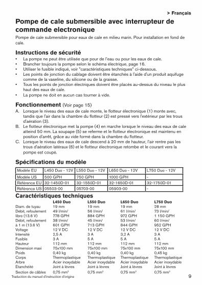
Caractéristiques techniques L450 Duo L550 Duo L650 Duo L750 Duo Diam. de tuyau 19 mm 19 mm 19 mm 28 mmDébit, refoulement 49 l/min/ 56 l/min/ 61 l/min/ 73 l/min/libre (13.6 V) 778 GPH 884 GPH 972 GPH 1 150 GPHDébit, refoulement 38 l/min/ 45 l/min/ 53 l/min/ 60 l/min/à 1 m (13.6 V) 601 GPH 713 GPH 844 GPH 952 GPH Voltage 12 V DC 12 V DC 12 V DC 12 V DC Intensité 2,5 A 3 A 3,2 A 3 A Fusible 3 A 5 A 5 A 5 A Hauteur 112 mm 112 mm 112 mm 112 mmDimension maxi 75x100 mm 75x100 mm 75x100 mm 75x100 mm Poids 0,40 kg 0,40 kg 0,40 kg 0,45 kgCorps Thermoplastique Thermoplastique Thermoplastique ThermoplastiqueArbre Acier inoxydable Acier inoxydable Acier inoxydable Acier inoxydableEtanchéité Joint à lèvres Joint à lèvres Joint à lèvres Joint à lèvres Section de câbles 0,75 mm2 0,75 mm2 0,75 mm2 0,75 mm2
Pompe de cale submersible avec interrupteur de commande electroniquePompe de cale submersible pour eaux de cale en milieu marin. Pour installation en fond de cale.
Instructions de sécurité• Lapompenepeutêtreutiliséequepourdel’eauoupourleseauxdecale.• Branchertoujourslapompeselonleschémaélectrique,page16.• Utiliserlefusibleindiqué,voir”caractéristiquestechniques”ci-dessous.• Lespointsdejonctionducablagedoiventêtreétanchésàl'aided'unproduitaquifuge
comme de la vaseline, du silicone ou de la graisse.• Touslespointsdejonctionélectriquesdoiventêtreplacésau-dessusduniveauleplus
haut des eaux de cale.• Lapompenedoitenaucuncastourneràvide.
Fonctionnement (Voir page 15)A. Lorsque le niveau des eaux de cale monte, le flotteur électronique (1) monte avec,
tandis que l'air dans la chambre du flotteur (2) est pressé vers l'extérieur par les trous d'aération (3).
B. Le flotteur électronique met la pompe (4) en marche lorsque le niveau des eaux de cale atteind 50 mm. La soupape (5) se referme et le flotteur électronique est maintenu en position d'arrêt, grâce au vide formé dans la chambre du flotteur.
C. Lorsque le niveau des eaux de cale descend à 20 mm de hauteur, l’air rentre pas les trous d'aération latéraux (6) et le flotteur électronique retombe et le courant vers la pompe est coupé.
Spécifications du modèleModèle EU L450 Duo - 12V L550 Duo - 12V L650 Duo - 12V L750 Duo - 12V
Modèle US 500 GPH 750 GPH 1000 GPH -Référence EU 32-1450D-01 32-1550D-01 32-1650D-01 32-1750D-01Référence US 05503-00 05703-00 05903-00 -
9
Traduction du manuel d'instruction d'origine
> Français
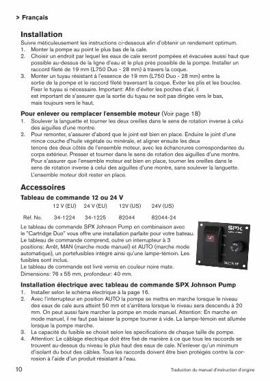
InstallationSuivre méticuleusement les instructions ci-dessous afin d’obtenir un rendement optimum.1. Monter la pompe au point le plus bas de la cale. 2. Choisir un endroit par lequel les eaux de cale seront pompées et évacuées aussi haut que
possible au-dessus de la ligne d’eau et le plus près possible de la pompe. Installer un raccord fileté de 19 mm (L750 Duo - 28 mm) à travers la coque.
3. Monter un tuyau résistant à l’essence de 19 mm (L750 Duo - 28 mm) entre la sortie de la pompe et le raccord fileté traversant la coque. Eviter les plis et les boucles.
Fixer le tuyau si nécessaire. Important: Afin d’éviter les poches d’air, il est important de s’assurer que la sortie du tuyau ne soit pas dirigée vers le bas, mais toujours vers le haut.
Pour enlever ou remplacer l'ensemble moteur (Voir page 18)1. Soulever la languette et tourner les deux oreilles dans le sens de rotation inverse à celui
des aiguilles d'une montre.2. Pour remonter, s’assurer d’abord que le joint est bien en place. Enduire le joint d’une
mince couche d’huile végétale ou minérale, et aligner ensuite les deux tenons des deux côtés de l’ensemble moteur, avec les échancrures correspondantes du
corps extérieur. Presser et tourner dans le sens de rotation des aiguilles d’une montre. Pour s’assurer que l’ensemble moteur est bien en place, tourner les oreilles dans le sens de rotation inverse à celui des aiguilles d’une montre, sans soulever la languette. L’ensemble moteur doit rester en place.
AccessoiresTableau de commande 12 ou 24 V
Le tableau de commande SPX Johnson Pump en combinaison avec le ”Cartridge Duo” vous offre une installation parfaite pour votre bateau. Le tableau de commande comprend, outre un interrupteur à 3 positions: Arrêt, MAN (marche mode manuel) et AUTO (marche mode automatique), un portefusibles intégré ainsi qu’une lampe-témoin. Les fusibles sont inclus.Le tableau de commande est livré vernis en couleur noire mate.Dimensions: 76 x 55 mm, profondeur: 40 mm.
Installation électrique avec tableau de commande SPX Johnson Pump1. Installer selon le schéma électrique à la page 16.2. Avec l’interrupteur en position AUTO la pompe se mettra en marche lorsque le niveau
des eaux de cale aura atteint 50 mm et s’arrêtera lorsque le niveau sera descendu à 20 mm. On peut aussi faire marcher la pompe en mode manuel. Attention: En marche en mode manuel, il ne faut pas laisser la pompe tourner à vide. La lampe-témoin est allumée lorsque la pompe marche.
3. La capacité du fusible se choisit selon les specifications de chaque taille de pompe.4. Attention: Le câblage électrique doit être fixé de manière à ce que tous les raccords se
trouvent au-dessus du niveau le plus haut des eaux de cale. N’enlever qu’un minimum d’isolant du bout des câbles. Tous les raccords doivent être bien protégés contre la cor-rosion à l’aide d’un produit résistant à l’eau.
12 V (EU) 24 V (EU) 12V (US) 24V (US)
Réf. No. 34-1224 34-1225 82044 82044-24
10
Traducción de instrucciones originales
> Español
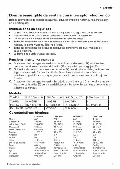
Características técnicas L450 Duo L550 Duo L650 Duo L750 Duo Manga 3/4" 3/4" 3/4" 1.1/8"Capacidad, 49 l/min/ 56 l/min/ 61 l/min/ 73 l/min/salida libre (13.6 V) 778 GPH 884 GPH 972 GPH 1.150 GPHCapacidad, 38 l/min/ 45 l/min/ 53 l/min/ 60 l/min/altura 1 m (13.6 V) 601 GPH 713 GPH 844 GPH 952 GPHTensión 12 V DC 12 V DC 12 V DC 12 V DC Amperaje 2,5 A 3 A 3,2 A 3 A Fusible 3 A 5 A 5 A 5 A Altura 112 mm 112 mm 112 mm 112 mm Dimensión maxima 75x100 mm 75x100 mm 75x100 mm 75x100 mm Peso 0,40 kg 0,40 kg 0,40 kg 0,45 kg Cuerpo Termoplástico Termoplástico Termoplástico TermoplásticoEje Acero inoxidable Acero inoxidable Acero inoxidable Acero inoxidableJunta eje Junta de labio Junta de labio Junta de labio Junta de labio Conductor 0,75 mm2 0,75 mm2 0,75 mm2 0,75 mm2
Bomba sumergible de sentina con interruptor electrónicoBomba submergible de sentina para achicar agua en ambiente marítimo. Para instalación en la contraquilla.
Instrucciónes de seguridad• Labombanosepuedeutilizarparaoutroslíquidossinoaguaoaguadesentina.• Instalarsiemprelabombasegúnelesquemaeléctricoenlapágina16.• Utilizarelfusibleindicadoenlascaracterísticastécnicasabajo.• Todaslasconexioneseléctricasdebensellarseconuncompuestoparaaplicaciones
marinas, tal como Vaselina, Silicona o grasa.• Todaslasconexioneseléctricasdebenquedarporencimadelnivelmásaltodel
agua de sentina.• Labombanopuedetrabajarenvacío.
Funcionamiento (Ver página 15)A. Cuando el nivel del agua de sentina sube, el flotador electrónico (1) sube tambien,
mientras que el aire en la caja del flotador (2) es expedido por el agujero (3).B. El flotador electrónico hace arrancar la bomba (4) cuando el nivel del agua de sentina
llega a una altura de 50 mm. La válvula (5) se cierra y el flotador electrónico se mantiene en posición de arranque, gracias al vacío que se crea dentro de la caja del flotador.
C. Cuando el nivel del agua de sentina ha bajado a una altura de 20 mm, el aire entra por los agujeros laterales (6) de la caja del flotador, mientras el flotador cae y la corriente a la bomba es cortada.
ModeloTipo EU L450 Duo - 12V L550 Duo - 12V L650 Duo - 12V L750 Duo - 12V
Tipo US 500 GPH 750 GPH 1000 GPH -Pieza No EU 32-1450D-01 32-1550D-01 32-1650D-01 32-1750D-01Pieza No US 05503-00 05703-00 05903-00 -
11

Traducción de instrucciones originales
> Español
InstalaciónSe recomienda observar estrictamente estas instrucciones de instalación para asegurar la mayor eficacia de la bomba de sentina.1. Montar la bomba en el punto más bajo de la sentina. 2. Elegir un punto por el que el agua de sentina se vaya a bombear fuera que esté lo más alejado
posible de la línea de flotación y a la menor distancia de la bomba. Instalar un accesorio de 3/4" (L750 Duo - 1,1/8") atravesando el casco.
3. Fijar una manga de 3/4" (L750 Duo - 1,1/8") resistente al petróleo de la salida de la bomba al accesorio que atraviesa el casco. Evitar cocas y lazos. Si fuera necesario, apoyar la manga. Observación: para evitar la entrada de aire, es importante no dejar que la manga caiga por debajo de la salida de la bomba. La manga debe presentar una elevación constante.
Para quitar o substituir la unidad motriz (Ver página 18)1. Levantar la lengüeta y girar las dos orejas en sentido contrario a lo de la rotación de las agujas
del reloj, y sacar la unidad motriz.2. Para montar de nuevo, asegurarse que la junta estea en su sitio. Untar la junta de una capa
menuda de aceite vegetal o mineral, y luego alinear los dos cames de los dos lados de la uni-dad motriz con las dos muescas del cuerpo exterior. Apretar y girar en el sentido de rotación de las agujas del reloj. Para asegurarse que la unidad motriz estea bien en su sitio, girar las orejas en el sentido contrário a lo de la rotación de las agujas del reloj sin levantar la lengüeta. La unidad motriz suele quedarse en su sitio.
Accesorios
Tablero 12 o 24 V
El tablero interruptor SPX Johnson Pump en combinación con el ”Cartridge Duo” le ofrece una instalación optimal.El interruptor del tablero tiene 3 posiciones: OFF (desconectado), MAN (conectado modo manual) AUTO (conectado modo automático). Lleva tambien un portafusible y una lámpara de control. Los fusibles van incluidos.El tablero lleva un acabado en negro mate.Dimensiones: 76 x 55 mm, 40 mm de fondo.
Instalación eléctrica con el tablero interruptor SPX Johnson Pump1. Instalar según el esquema eléctrico en la página 16.2. Con el interruptor en posición AUTO la bomba arrancará cuando el nivel del agua de sentina
llegar a una altura de 50 mm y parará cuando el nivel bajar hasta 20 mm. Se puede tambien hacer trabajar la bomba en modo manual.
¡Attención! En modo manual no se puede hacer trabajar la bomba en vacío. La lámpara de control se encende cuando la bomba trabaja.
3. La capacídad del fusible depende del tamaño de la bomba.4. ¡Importante! Todo el cableado debe fijarse de manera que las conexiones queden lo mas alto
posible por encima del nivel del agua de sentina. No quitar mas que necesario del aislante de la punta de los cabos eléctricos. Todas las conexiones deben aislarse con un producto a prueva de agua para evitar la corrosión.
12 V (EU) 24 V (EU) 12V (US) 24V (US)
Pieza No. 34-1224 34-1225 82044 82044-24
12

Traduzione delle istruzioni originali
> Italiano
Caratteristiche tecniche L450 Duo L550 Duo L650 Duo L750 Duo Sezione tubo 3/4" 3/4" 3/4" 1.1/8"Portata massima (13.6 V) 49 l/min/778 GPH 56 l/min/884 GPH 61 l/min/972 GPH 73 l/min/1.150 GPHPortata a 1 mt 38 l/min/ 45 l/min/ 53 l/min/ 60 l/min/di prevalenza (13.6 V) 601 GPH 713 GPH 844 GPH 952 GPH Voltaggio 12 V DC 12 V DC 12 V DC 12 V DC Amperaggio 2,5 A 3 A 3,2 A 3 A Capacità fusibile 3 A 5 A 5 A 5 A Altezza 112 mm 112 mm 112 mm 112 mm Dimenzione massima 75x100 mm 75x100 mm 75x100 mm 75x100 mm Peso 0,40 kg 0,40 kg 0,40 kg 0,45 kgCorpo Termoplastico Termoplastico Termoplastico TermoplasticoAlbero Acciaio inossidabile Acciaio inossidabile Acciaio inossidabile Acciaio inossidabileGuarnizione albero Tipo "Corteco" Tipo "Corteco" Tipo "Corteco" Tipo "Corteco" Area cavo 0,75 mm2 0,75 mm2 0,75 mm2 0,75 mm2
Pompa di sentina sommersa con interruttore elettronicoPompa di sentina sommersa per pompare l’acqua di sentina in ambiente marino. Per installazione in sentina.
Istruzioni di sicurezza• Lapompanosipuòusareperaltriliquididell'acquaodell’acquadisentina.• Installaresemprelapompasecondoloschemaelettriconellapagina16.• Usareilfusibileindicato,vederelecaratteristichetecnicheinbasso.• Icollegamentielettricidovrebberoesseresigillaticonunsigillantemarinocome
per esempio, Vaselina, Silicona o grasso.• Tuttiicollegamentielettricidevonoesserepostialdisopradellivellopiùalto
dell'acqua.• Lapompanopuógirareavuoto.
Funzionamento (Vedi pagina 15)A. Quando il livello dell’acqua di sentina si alza, il galleggiante elettronico (1) sale,
mentre l’aria nella cassa del galleggiante (2) è espulsa da apposito foro (3).B. Il galleggiante elettronico mette la pompa (4) in marcia quando il livello dell’acqua
arriva a una altezza di 50 mm. La valvola (5) si chiude ed il galleggiante si ferma in posizione iniziale, grazie al vuoto dentro alla cassa del galleggiante.
C. Quando il livello dell’acqua di sentina si abbassa al livello di 20 mm, l’aria entra per gli orifizi laterali (6) della cassa del galleggiante ed allora il galleggiante si abbassa e la corrente alla pompa è interrotta.
Specifica del tipo Tipo EU L450 Duo - 12V L550 Duo - 12V L650 Duo - 12V L750 Duo - 12V
Tipo US 500 GPH 750 GPH 1000 GPH -Art. No EU 32-1450D-01 32-1550D-01 32-1650D-01 32-1750D-01Art. No US 05503-00 05703-00 05903-00 -
13
Traduzione delle istruzioni originali
> Italiano
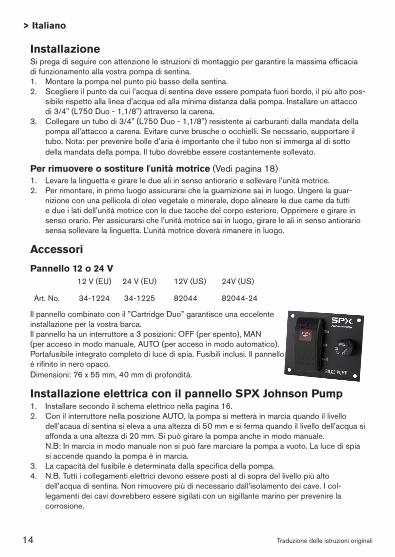
InstallazioneSi prega di seguire con attenzione le istruzioni di montaggio per garantire la massima efficacia di funzionamento alla vostra pompa di sentina.1. Montarelapompanelpuntopiùbassodellasentina.2. Scegliereilpuntodacuil’acquadisentinadeveesserepompatafuoribordo,ilpiùaltopos-
sibile rispetto alla linea d’acqua ed alla minima distanza dalla pompa. Installare un attacco di 3/4" (L750 Duo - 1,1/8") attraverso la carena.
3. Collegare un tubo di 3/4" (L750 Duo - 1,1/8") resistente ai carburanti dalla mandata della pompa all’attacco a carena. Evitare curve brusche o occhielli. Se necssario, supportare il tubo. Nota: per prevenire bolle d’aria è importante che il tubo non si immerga al di sotto della mandata della pompa. Il tubo dovrebbe essere costantemente sollevato.
Per rimuovere o sostiture l'unità motrice (Vedi pagina 18)1. Levare la linguetta e girare le due ali in senso antiorario e sollevare l’unità motrice.2. Per rimontare, in primo luogo assicurarsi che la guarnizione sai in luogo. Ungere la guar-
nizione con una pellicola di oleo vegetale o minerale, dopo alineare le due came da tutti e due i lati dell’unità motrice con le due tacche del corpo esteriore. Opprimere e girare in senso orario. Per assicurarsi che l’unità motrice sai in luogo, girare le ali in senso antiorario sensa sollevare la linguetta. L’unità motrice doverà rimanere in luogo.
Accessori
Pannello 12 o 24 V
Il pannello combinato con il ”Cartridge Duo” garantisce una eccelente installazione per la vostra barca.Il pannello ha un interruttore a 3 posizioni: OFF (per spento), MAN (per acceso in modo manuale, AUTO (per acceso in modo automatico). Portafusibile integrato completo di luce di spia. Fusibili inclusi. Il pannelloé rifinito in nero opaco. Dimensioni: 76 x 55 mm, 40 mm di profonditá.
Installazione elettrica con il pannello SPX Johnson Pump1. Installare secondo il schema elettrico nella pagina 16.2. Con il interruttore nella posizione AUTO, la pompa si metterà in marcia quando il livello
dell’acaua di sentina si eleva a una altezza di 50 mm e si ferma quando il livello dell’acqua si affondaaunaaltezzadi20mm.Sipuògirarelapompaancheinmodomanuale.
N.B:Inmarciainmodomanualenonsipuòfaremarciarelapompaavuoto.Lalucedispiasi accende quando la pompa è in marcia.
3. La capacità del fusibile è determinata dalla specifica della pompa.4. N.B.Tuttiicollegamentielettricidevonoesserepostialdisopradellivellopiùalto
dell’acquadisentina.Nonrimuoverepiùdinecessariodall’isolamentodeicave.Icol-legamenti dei cavi dovrebbero essere sigilati con un sigillante marino per prevenire la corrosione.
12 V (EU) 24 V (EU) 12V (US) 24V (US)
Art. No. 34-1224 34-1225 82044 82044-24
14
15
A
B
C
1
2
4
5
3
50 mm
6
20 mm
16
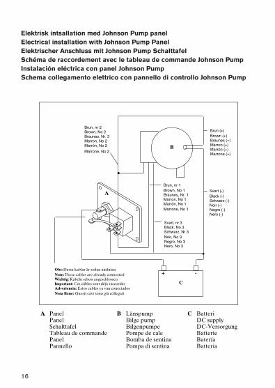
Elektrisk intsallation med Johnson Pump panelElectrical installation with Johnson Pump PanelElektrischer Anschluss mit Johnson Pump SchalttafelSchéma de raccordement avec le tableau de commande Johnson PumpInstalación eléctrica con panel Johnson PumpSchema collegamento elettrico con pannello di controllo Johnson Pump
17
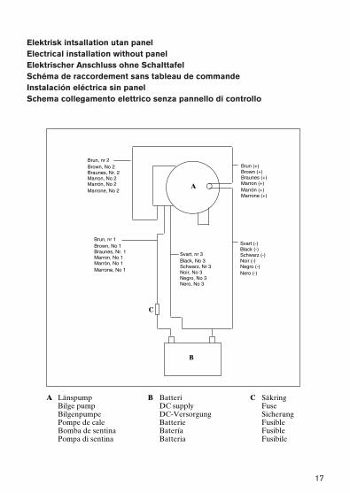
Elektrisk intsallation utan panelElectrical installation without panelElektrischer Anschluss ohne SchalttafelSchéma de raccordement sans tableau de commandeInstalación eléctrica sin panelSchema collegamento elettrico senza pannello di controllo

18
MonteraReinstallMontierenRemonterMontrarRimontare
DemonteraRemoveEntfernenEnleverQuitarRimuovere
Lyft låshakenLift tabDie Zunge hebenSoulever la languetteLevantar la lengüetaLevare la linguetta
Lägsta sugnivå, mått ”A”Lowest level for suction, measure ”A”Niedrigste Ansaughöhe, Abmessung ”A”Plus bas niveau pour la succion, mesure ”A”Altura mínima de aspiración, medida ”A”Livellopiùbassoperaspirazione,misura”A”
L450 Duo – 8 mmL550 Duo – 8 mmL650 Duo – 8 mmL750 Duo – 8 mm
A
TätningSealDichtungJointJuntaGuarnizione

Avfallshantering/materialåtervinningVid avfallshantering ska produkten lämnas för destruktion/återvinning enligt gällande lagstiftning. Vid tillämpliga fall demonteras och sorteras produkten i ingående materialfraktioner.
Waste handling/material recyclingAt the products end of life, please dispose of the product according to applicable law. Where applicable, please disassemble the product and recycle the parts material.
Entsorgung/Recycling Nach Lebensdauerende entsorgen Sie die Pumpe nach den örtlichen Vorschriften. Nach Möglichkeit demontieren Sie Teile der Pumpe um sie dem Recycling-Process zuzuführen.
Gestion des déchets/recyclage des matériauxLorsque le matériel arrivera en fin de vie, veuillez le mettre au rebut en fonction des lois applicables. Lorsque c'est possible, veuillez démonter le matériel et recycler les pièces pouvant l'être
Desguace/RecicladoAl final de la vida del equipo disponga de este de acuerdo a la ley. Donde sea de aplicación desmonte el equipo y recicle los diferentes materiales.
Gestione dei rifiuti/riciclaggio dei materialiAl termine della vita del prodotto si prega di smaltire il prodotto secondo le leggi in vigore per queste operazioni. Quando possibile, si raccomanda di smontare il prodotto e riciclare i materiali dei componenti.

20
S PX FLOW TECH NOLOGY SWE D E N AB
Nastagatan 19, P.O. Box 1436
SE-701 14 Örebro, Sweden
P: +46 (0)19 21 83 00
F: +46 (0)19 27 23 72
JOH N SON PU M PS OF AM E R ICA I NC
1625 Hunter Road, Suite B,
Hanover Park, Illinois, 60133, USA
P: +1 847 671 7867
F: +1 847 671 7909
SPX reserves the right to incorporate our latest design and material
changes without notice or obligation. Design features, materials of
construction and dimensionals data, as described in this bulletin, are
provided for your information only and should not be relied upon unless
confirmed in writing.
Please contact your local sales representative for product availability in
your region. For more information visit www.spx.com.
ISSUED 09/2012 IB-107 R06
COPYRIGHT ©2012 SPX Corporation
Cartridge Duo L450 D UO, L550 D UO, L650 D UO,
L750 D UO