Embed Size (px)
Citation preview
Process ManagementTM
Type FA and FAG
CARTRIDGE FILTERS
Type FAG
Type FA
2
FA and FAG Filters
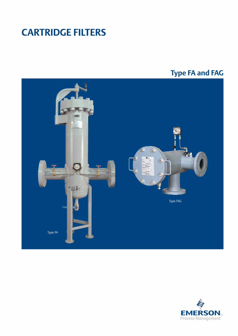
Cartridge Filters
Filters are intended to screen out larger pieces of foreign particles, often present in the gases or particularly during the initial stages of operation of newly laid pipes, to minimize damage to valves, pressure regulators, meters and other equipment used in regulating and metering stations.
Our filters can be used with natural gas and other non-aggressive gases.
They come in several versions to meet all application demands.
They have threaded connections for the mounting of the drain cock (supplied on request) and other accessories.
All our filters can be fitted upon request with a differential pressure gauge as clog detector.
The filters are of sturdy manufacture in special steel and are very easy to install and service.
The cloth filter element can handle particles as small as 5µ and can be used for both dry and wet gas.
The main features are as follows:
• Versatility
•Easymaintenance
•Axialandright-angleconnections
•Filteringdegree5 µm
Available Versions
FA Series: High pressure filters
FAG Series: Mid and low pressure filters
FG/07 Type: Mid and low pressure filters with threaded connections
3
FA and FAG Filters
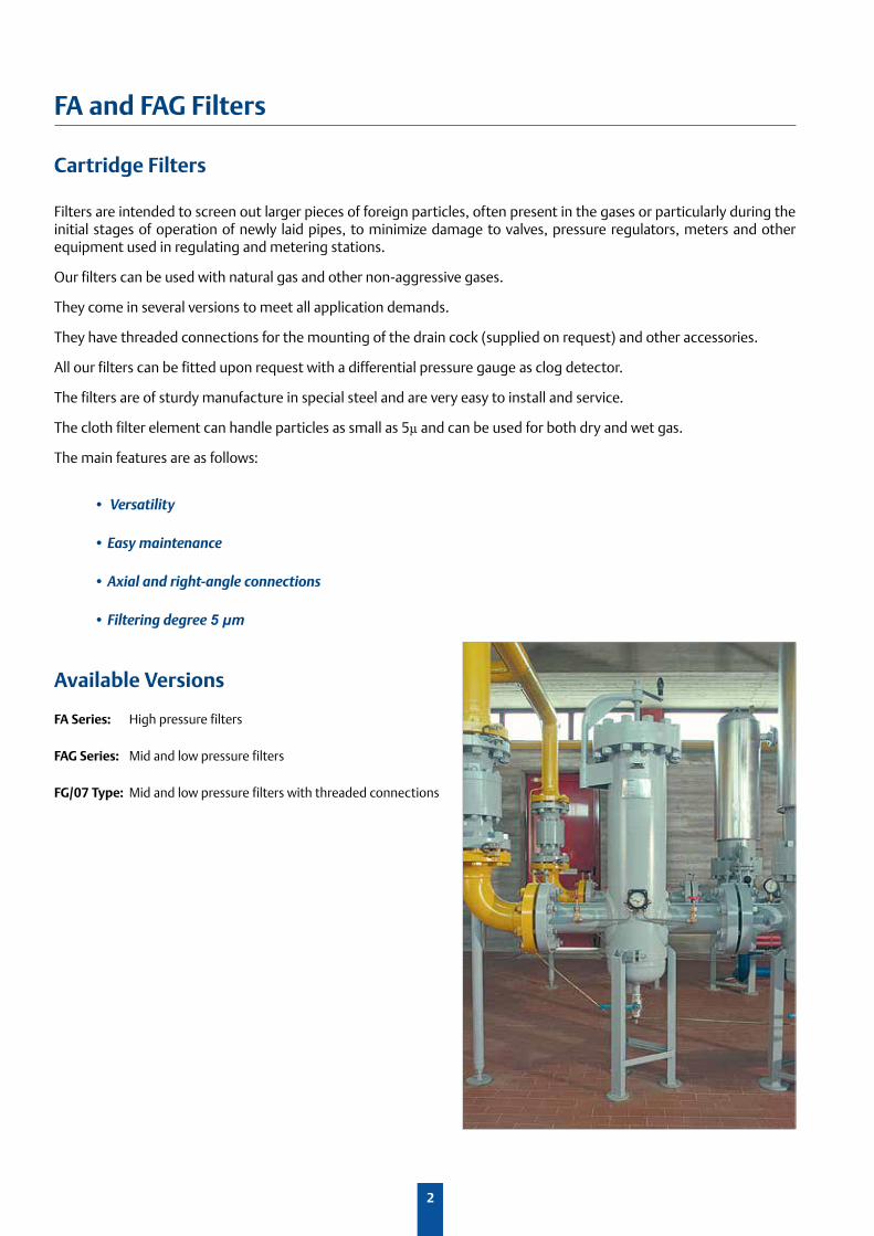
FA Series • High Pressure Filters
Type RatingDesign Pressure PS
(bar)Hydrostatic Test PT
(bar)
FA/ • FA-11/ ANSI 150 17 25.5
FA/ • FA-12/ ANSI 300 30 45
FA-AP/ • FA-12-AP/ ANSI 600 90 135
Flanged Connections
ANSI 150 - 300 - 600
DN 50 - 65 - 80 - 100 - 150 - 200 - 250 - 300 - 350 - 400
Temperature
Standard version: Working -10 °C +100 °C
Low temperature version: Working -20 °C +100 °C
Technical Features
4
FA and FAG Filters
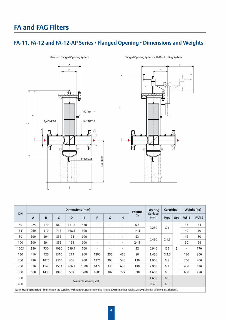
FA-11, FA-12 and FA-12-AP Series • Flanged Opening • Dimensions and Weights
D
E
A
Standard Flanged Opening System
1/2” NPT-F
1” GAS-M
1/4” NPT-F1/4” NPT-F
DN
B
C
See
Not
e
DN
H H
G
F
Flanged Opening System with Davit Lifting System
DNDimensions (mm)
Volume (l)
Filtering Surface
(m2)
Cartridge Weight (kg)
A B C D E F G H Type Qty FA/11 FA/12
50 225 470 660 141.3 450 - - - 8.50.250 G 1
2
35 44
65 260 510 715 168.3 500 - - - 14.5 40 50
80 300 594 855 194 600 - - - 230.460 G 1.5
46 80
100 300 594 855 194 600 - - - 24.5 50 94
100S 380 730 1030 219.1 700 - - - 32 0.940 G 2 - 170
150 410 920 1310 273 800 1200 255 470 80 1.450 G 2.5 190 300
200 480 1026 1360 356 900 1326 300 540 130 1.900 G 3 260 400
250 570 1140 1553 406.4 1000 1477 335 630 189 2.900 G 4 450 690
300 660 1436 1980 508 1200 1685 387 727 390 4.600 G 5 650 980
350Available on request
4.600 G 5
400 8.40 G 6
Note: Starting from DN 150 the filters are supplied with support (recommended height 800 mm, other heights are available for different installations).
5
FA and FAG Filters
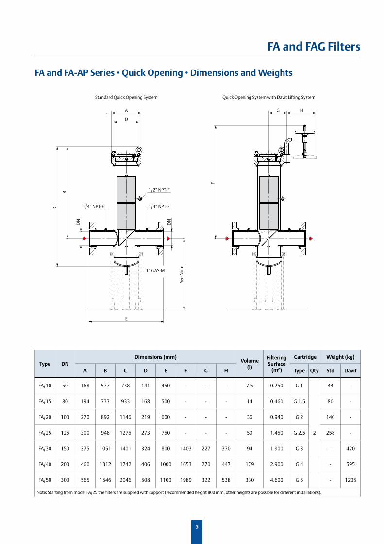
FA and FA-AP Series • Quick Opening • Dimensions and Weights
D
E
A
Standard Quick Opening System
1/2” NPT-F
1” GAS-M
1/4” NPT-F1/4” NPT-F
DN
B
C
DN
HG
F
Quick Opening System with Davit Lifting System
See
Not
e
Type DNDimensions (mm)
Volume (l)
Filtering Surface
(m2)
Cartridge Weight (kg)
A B C D E F G H Type Qty Std Davit
FA/10 50 168 577 738 141 450 - - - 7.5 0.250 G 1
2
44 -
FA/15 80 194 737 933 168 500 - - - 14 0.460 G 1.5 80 -
FA/20 100 270 892 1146 219 600 - - - 36 0.940 G 2 140 -
FA/25 125 300 948 1275 273 750 - - - 59 1.450 G 2.5 258 -
FA/30 150 375 1051 1401 324 800 1403 227 370 94 1.900 G 3 - 420
FA/40 200 460 1312 1742 406 1000 1653 270 447 179 2.900 G 4 - 595
FA/50 300 565 1546 2046 508 1100 1989 322 538 330 4.600 G 5 - 1205
Note: Starting from model FA/25 the filters are supplied with support (recommended height 800 mm, other heights are possible for different installations).
6
FA and FAG Filters
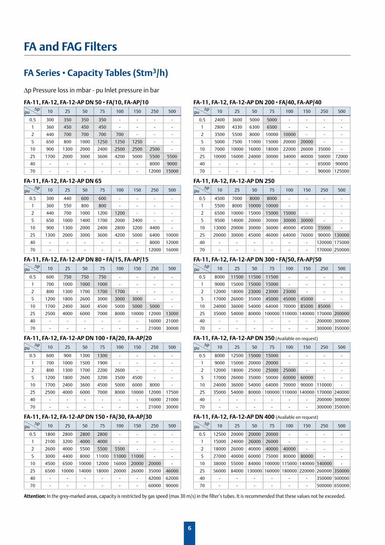
FA Series • Capacity Tables (Stm3/h)
FA-11, FA-12, FA-12-AP DN 50 • FA/10, FA-AP/10
10 25 50 75 100 150 250 500
0.5 300 350 350 350 - - - -
1 360 450 450 450 - - - -
2 440 700 700 700 700 - - -
5 650 800 1000 1250 1250 1250 - -
10 900 1300 2000 2400 2500 2500 2500 -
25 1700 2000 3000 3600 4200 5000 5500 5500
40 - - - - - - 8000 9000
70 - - - - - - 12000 15000
FA-11, FA-12, FA-12-AP DN 200 • FA/40, FA-AP/40
10 25 50 75 100 150 250 500
0.5 2400 3600 5000 5000 - - - -
1 2800 4330 6300 6500 - - - -
2 3500 5500 8000 10000 10000 - - -
5 5000 7500 11000 15000 20000 20000 - -
10 7000 10000 16000 18000 22000 26000 35000 -
25 10000 16000 24000 30000 34000 40000 50000 72000
40 - - - - - - 65000 90000
70 - - - - - - 90000 125000
FA-11, FA-12, FA-12-AP DN 80 • FA/15, FA-AP/15
10 25 50 75 100 150 250 500
0.5 600 750 750 750 - - - -
1 700 1000 1000 1000 - - - -
2 800 1300 1700 1700 1700 - - -
5 1200 1800 2600 3000 3000 3000 - -
10 1700 2400 3600 4500 5000 5000 5000 -
25 2500 4000 6000 7000 8000 10000 12000 13000
40 - - - - - - 16000 21000
70 - - - - - - 21000 30000
FA-11, FA-12, FA-12-AP DN 300 • FA/50, FA-AP/50
10 25 50 75 100 150 250 500
0.5 8000 11500 11500 11500 - - - -
1 9000 15000 15000 15000 - - - -
2 12000 18000 23000 23000 23000 - - -
5 17000 26000 35000 45000 45000 45000 - -
10 24000 36000 54000 64000 70000 85000 85000 -
25 35000 54000 80000 100000 110000 140000 170000 200000
40 - - - - - - 200000 300000
70 - - - - - - 300000 350000
FA-11, FA-12, FA-12-AP DN 65
10 25 50 75 100 150 250 500
0.5 300 440 600 600 - - - -
1 360 550 800 800 - - - -
2 440 700 1000 1200 1200 - - -
5 650 1000 1400 1700 2000 2400 - -
10 900 1300 2000 2400 2800 3200 4400 -
25 1300 2000 3000 3600 4200 5000 6400 10000
40 - - - - - - 8000 12000
70 - - - - - - 12000 16000
FA-11, FA-12, FA-12-AP DN 250
10 25 50 75 100 150 250 500
0.5 4500 7000 8000 8000 - - - -
1 5500 8000 10000 10000 - - - -
2 6500 10000 15000 15000 15000 - - -
5 9500 14000 20000 30000 30000 30000 - -
10 13000 20000 30000 36000 40000 45000 55000 -
25 20000 30000 45000 46000 64000 76000 90000 130000
40 - - - - - - 120000 175000
70 - - - - - - 170000 250000
FA-11, FA-12, FA-12-AP DN 100 • FA/20, FA-AP/20
10 25 50 75 100 150 250 500
0.5 600 900 1300 1300 - - - -
1 700 1000 1500 1900 - - - -
2 800 1300 1700 2200 2600 - - -
5 1200 1800 2600 3200 3500 4500 - -
10 1700 2400 3600 4500 5000 6000 8000 -
25 2500 4000 6000 7000 8000 10000 12000 17500
40 - - - - - - 16000 21000
70 - - - - - - 21000 30000
FA-11, FA-12, FA-12-AP DN 350 (Available on request)
10 25 50 75 100 150 250 500
0.5 8000 12500 15000 15000 - - - -
1 9000 15000 20000 20000 - - - -
2 12000 18000 25000 25000 25000 - - -
5 17000 26000 35000 50000 60000 60000 - -
10 24000 36000 54000 64000 70000 90000 110000 -
25 35000 54000 80000 100000 110000 140000 170000 240000
40 - - - - - - 200000 300000
70 - - - - - - 300000 350000
FA-11, FA-12, FA-12-AP DN 150 • FA/30, FA-AP/30
10 25 50 75 100 150 250 500
0.5 1800 2800 2800 2800 - - - -
1 2100 3200 4000 4000 - - - -
2 2600 4000 5500 5500 5500 - - -
5 3000 4400 8000 11000 11000 11000 - -
10 4500 6500 10000 12000 16000 20000 20000 -
25 6500 10000 14000 18000 20000 26000 35000 46000
40 - - - - - - 42000 62000
70 - - - - - - 60000 90000
FA-11, FA-12, FA-12-AP DN 400 (Available on request)
10 25 50 75 100 150 250 500
0.5 12500 20000 20000 20000 - - - -
1 15000 24000 26000 26000 - - - -
2 18000 26000 40000 40000 40000 - - -
5 27000 40000 60000 75000 80000 80000 - -
10 38000 55000 84000 100000 115000 140000 140000 -
25 56000 84000 130000 160000 180000 220000 260000 350000
40 - - - - - - 350000 500000
70 - - - - - - 500000 650000
Δp Δp
Δp Δp
Δp Δp
Δp Δp
Δp Δp
pu pu
pu pu
pu pu
pu pu
pu pu
Δp Pressure loss in mbar - pu Inlet pressure in bar
Attention: In the grey-marked areas, capacity is restricted by gas speed (max 30 m/s) in the filter’s tubes. It is recommended that these values not be exceeded.
7
FA and FAG Filters
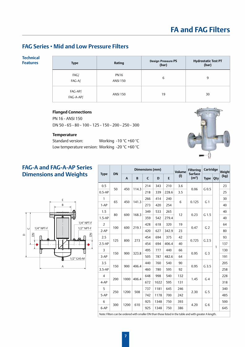
FAG Series • Mid and Low Pressure Filters
Type RatingDesign Pressure PS
(bar)Hydrostatic Test PT
(bar)
FAG/
FAG-A/
PN16
ANSI 150 6 9
FAG-AP/
FAG-A-AP/ANSI 150 19 30
Flanged Connections
PN 16 - ANSI 150
DN 50 - 65 - 80 - 100 - 125 - 150 - 200 - 250 - 300
Temperature
Standard version: Working -10 °C +60 °C
Low temperature version: Working -20 °C +60 °C
FAG-A and FAG-A-AP SeriesDimensions and Weights
Technical Features
B
A
E
C
D
1/2” NPT-F
1/2” GAS-M
1/4” NPT-F
1/4” NPT-F
DN
DN
Type DNDimensions (mm)
Volume (l)
FilteringSurface
(m2)
CartridgeWeight
(kg)A B C D E Type Qty
0.550 450 114.3
214 343 210 3.60.06 G 0.5
1
23
0.5-AP 218 339 228.6 3.5 25
165 450 141.3
266 414 2406 0.125 G 1
30
1-AP 273 420 254 40
1.580 600 168.3
349 533 26512 0.23 G 1.5
40
1.5-AP 359 542 279.4 40
2100 600 219.1
428 618 320 190.47 G 2
64
2-AP 420 627 342.9 23 80
2.5125 800 273
454 694 375 420.725 G 2.5
93
2.5-AP 454 694 406.4 40 137
3150 900 323.8
495 777 440 660.95 G 3
130
3-AP 505 787 482.6 64 191
3.5150 900 406.4
440 760 540 900.95 G 3.5
205
3.5-AP 460 780 595 92 258
4200 1000 406.4
648 998 540 1321.45 G 4
228
4-AP 672 1022 595 131 318
5250 1200 508
737 1181 645 2462.30 G 5
340
5-AP 742 1178 700 242 485
6300 1200 610
925 1348 750 3934.20 G 6
500
6-AP 925 1348 750 386 645
Note: Filters can be ordered with smaller DN than those listed in the table and with greater A length.
8
FA and FAG Filters
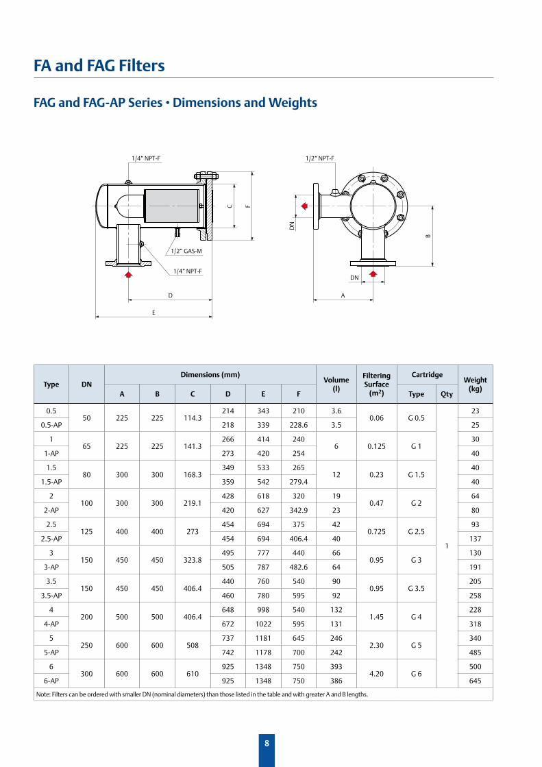
FAG and FAG-AP Series • Dimensions and Weights
B
A
E
C F
D
1/2” NPT-F
1/2” GAS-M
1/4” NPT-F
1/4” NPT-F
DN
DN
Type DNDimensions (mm)
Volume (l)
FilteringSurface
(m2)
CartridgeWeight
(kg)A B C D E F Type Qty
0.550 225 225 114.3
214 343 210 3.60.06 G 0.5
1
23
0.5-AP 218 339 228.6 3.5 25
165 225 225 141.3
266 414 2406 0.125 G 1
30
1-AP 273 420 254 40
1.580 300 300 168.3
349 533 26512 0.23 G 1.5
40
1.5-AP 359 542 279.4 40
2100 300 300 219.1
428 618 320 190.47 G 2
64
2-AP 420 627 342.9 23 80
2.5125 400 400 273
454 694 375 420.725 G 2.5
93
2.5-AP 454 694 406.4 40 137
3150 450 450 323.8
495 777 440 660.95 G 3
130
3-AP 505 787 482.6 64 191
3.5150 450 450 406.4
440 760 540 900.95 G 3.5
205
3.5-AP 460 780 595 92 258
4200 500 500 406.4
648 998 540 1321.45 G 4
228
4-AP 672 1022 595 131 318
5250 600 600 508
737 1181 645 2462.30 G 5
340
5-AP 742 1178 700 242 485
6300 600 600 610
925 1348 750 3934.20 G 6
500
6-AP 925 1348 750 386 645
Note: Filters can be ordered with smaller DN (nominal diameters) than those listed in the table and with greater A and B lengths.
9
FA and FAG Filters
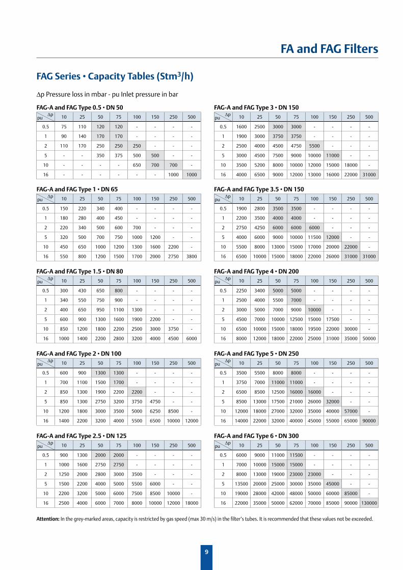
FAG Series • Capacity Tables (Stm3/h)
FAG-A and FAG Type 0.5 • DN 50
10 25 50 75 100 150 250 500
0.5 75 110 120 120 - - - -
1 90 140 170 170 - - - -
2 110 170 250 250 250 - - -
5 - - 350 375 500 500 - -
10 - - - - 650 700 700 -
16 - - - - - - 1000 1000
FAG-A and FAG Type 3 • DN 150
10 25 50 75 100 150 250 500
0.5 1600 2500 3000 3000 - - - -
1 1900 3000 3750 3750 - - - -
2 2500 4000 4500 4750 5500 - - -
5 3000 4500 7500 9000 10000 11000 - -
10 3500 5200 8000 10000 12000 15000 18000 -
16 4000 6500 9000 12000 13000 16000 22000 31000
FAG-A and FAG Type 1.5 • DN 80
10 25 50 75 100 150 250 500
0.5 300 430 650 800 - - - -
1 340 550 750 900 - - - -
2 400 650 950 1100 1300 - - -
5 600 900 1300 1600 1900 2200 - -
10 850 1200 1800 2200 2500 3000 3750 -
16 1000 1400 2200 2800 3200 4000 4500 6000
FAG-A and FAG Type 4 • DN 200
10 25 50 75 100 150 250 500
0.5 2250 3400 5000 5000 - - - -
1 2500 4000 5500 7000 - - - -
2 3000 5000 7000 9000 10000 - - -
5 4500 7000 10000 12500 15000 17500 - -
10 6500 10000 15000 18000 19500 22000 30000 -
16 8000 12000 18000 22000 25000 31000 35000 50000
FAG-A and FAG Type 1 • DN 65
10 25 50 75 100 150 250 500
0.5 150 220 340 400 - - - -
1 180 280 400 450 - - - -
2 220 340 500 600 700 - - -
5 320 500 700 750 1000 1200 - -
10 450 650 1000 1200 1300 1600 2200 -
16 550 800 1200 1500 1700 2000 2750 3800
FAG-A and FAG Type 3.5 • DN 150
10 25 50 75 100 150 250 500
0.5 1900 2800 3500 3500 - - - -
1 2200 3500 4000 4000 - - - -
2 2750 4250 6000 6000 6000 - - -
5 4000 6000 9000 10000 11500 12000 - -
10 5500 8000 13000 15000 17000 20000 22000 -
16 6500 10000 15000 18000 22000 26000 31000 31000
FAG-A and FAG Type 2 • DN 100
10 25 50 75 100 150 250 500
0.5 600 900 1300 1300 - - - -
1 700 1100 1500 1700 - - - -
2 850 1300 1900 2200 2200 - - -
5 850 1300 2750 3200 3750 4750 - -
10 1200 1800 3000 3500 5000 6250 8500 -
16 1400 2200 3200 4000 5500 6500 10000 12000
FAG-A and FAG Type 5 • DN 250
10 25 50 75 100 150 250 500
0.5 3500 5500 8000 8000 - - - -
1 3750 7000 11000 11000 - - - -
2 6500 8500 12500 16000 16000 - - -
5 8500 13000 17500 21000 26000 32000 - -
10 12000 18000 27000 32000 35000 40000 57000 -
16 14000 22000 32000 40000 45000 55000 65000 90000
FAG-A and FAG Type 2.5 • DN 125
10 25 50 75 100 150 250 500
0.5 900 1300 2000 2000 - - - -
1 1000 1600 2750 2750 - - - -
2 1250 2000 2800 3000 3500 - - -
5 1500 2200 4000 5000 5500 6000 - -
10 2200 3200 5000 6000 7500 8500 10000 -
16 2500 4000 6000 7000 8000 10000 12000 18000
FAG-A and FAG Type 6 • DN 300
10 25 50 75 100 150 250 500
0.5 6000 9000 11000 11500 - - - -
1 7000 10000 15000 15000 - - - -
2 8000 13000 19000 23000 23000 - - -
5 13500 20000 25000 30000 35000 45000 - -
10 19000 28000 42000 48000 50000 60000 85000 -
16 22000 35000 50000 62000 70000 85000 90000 130000
Δp Δp
Δp Δp
Δp Δp
Δp Δp
Δp Δp
pu pu
pu pu
pu pu
pu pu
pu pu
Δp Pressure loss in mbar - pu Inlet pressure in bar
Attention: In the grey-marked areas, capacity is restricted by gas speed (max 30 m/s) in the filter’s tubes. It is recommended that these values not be exceeded.
10
FA and FAG Filters
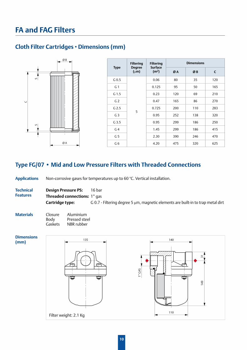
Materials Closure AluminiumBody Pressed steelGaskets NBR rubber
Dimensions (mm)
Cloth Filter Cartridges • Dimensions (mm)
Ø B
Ø A
5
C
5
135 140
110
1” G
AS
149
31
TypeFiltering Degree
(µm)
Filtering Surface
(m2)
Dimensions
Ø A Ø B C
G 0.5
5
0.06 80 35 120
G 1 0.125 95 50 165
G 1.5 0.23 120 69 210
G 2 0.47 165 86 270
G 2.5 0.725 200 110 283
G 3 0.95 252 138 320
G 3.5 0.95 299 186 250
G 4 1.45 299 186 415
G 5 2.30 390 246 470
G 6 4.20 475 320 625
Design Pressure PS: 16 bar
Threaded connections: 1” gas
Cartridge type: G 0.7 - Filtering degree 5 µm, magnetic elements are built-in to trap metal dirt
Type FG/07 • Mid and Low Pressure Filters with Threaded Connections
Technical Features
Applications Non-corrosive gases for temperatures up to 60 °C. Vertical installation.
Filter weight: 2.1 Kg
11
FA and FAG Filters
PG/150
mbar
psid
PG/... PG/...-S
90
80
80
70
Inlet OutletPG/150
mbar
psid
Inlet valve Outlet valve
By-pass
96 90
50
120
Inlet Outlet
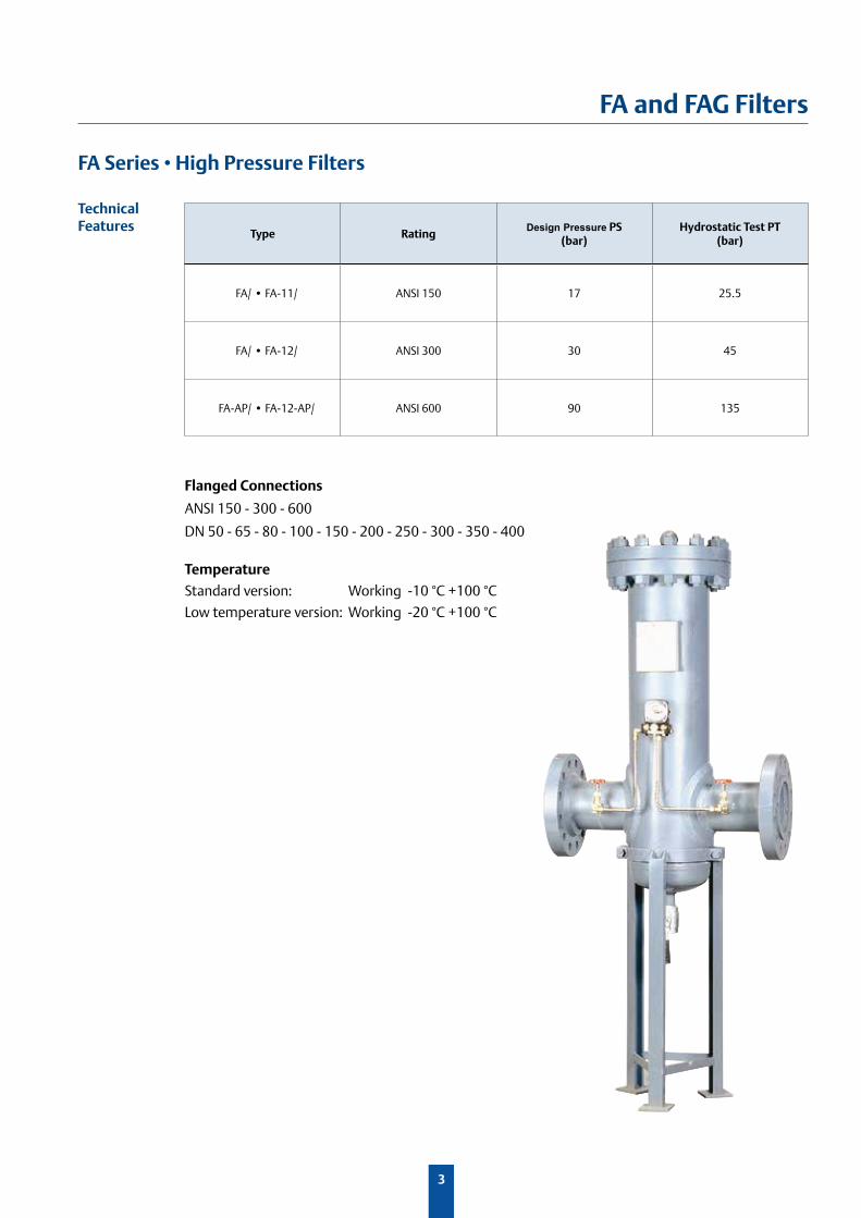
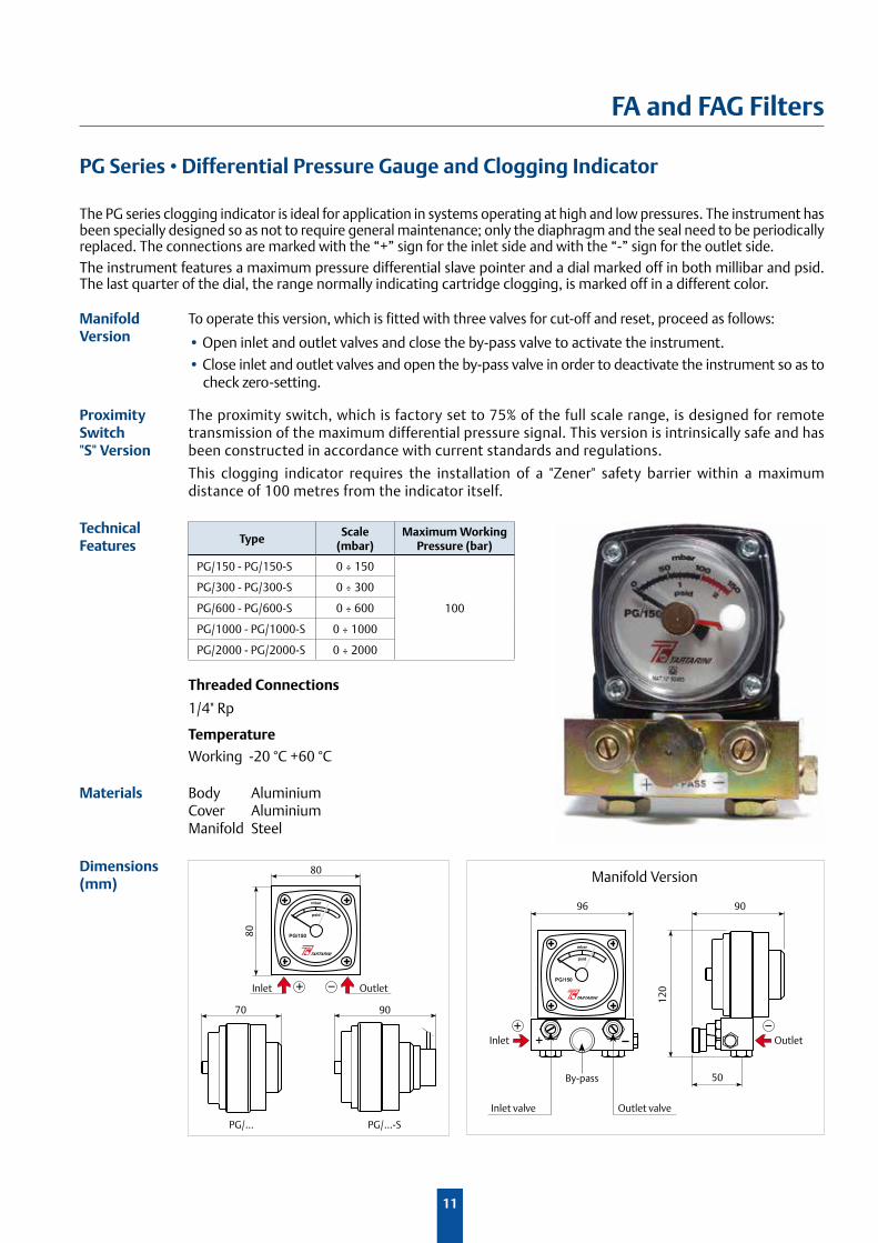
PG Series • Differential Pressure Gauge and Clogging Indicator
The PG series clogging indicator is ideal for application in systems operating at high and low pressures. The instrument has been specially designed so as not to require general maintenance; only the diaphragm and the seal need to be periodically replaced. The connections are marked with the “+” sign for the inlet side and with the “-” sign for the outlet side. The instrument features a maximum pressure differential slave pointer and a dial marked off in both millibar and psid. The last quarter of the dial, the range normally indicating cartridge clogging, is marked off in a different color.
Manifold Version
To operate this version, which is fitted with three valves for cut-off and reset, proceed as follows:
• Open inlet and outlet valves and close the by-pass valve to activate the instrument.
• Close inlet and outlet valves and open the by-pass valve in order to deactivate the instrument so as to check zero-setting.
Proximity Switch "S" Version
The proximity switch, which is factory set to 75% of the full scale range, is designed for remote transmission of the maximum differential pressure signal. This version is intrinsically safe and has been constructed in accordance with current standards and regulations.
This clogging indicator requires the installation of a "Zener" safety barrier within a maximum distance of 100 metres from the indicator itself.
Technical Features
Materials Body Aluminium Cover AluminiumManifold Steel
Dimensions(mm) Manifold Version
TypeScale
(mbar)Maximum Working
Pressure (bar)
PG/150 - PG/150-S 0 ÷ 150
100
PG/300 - PG/300-S 0 ÷ 300
PG/600 - PG/600-S 0 ÷ 600
PG/1000 - PG/1000-S 0 ÷ 1000
PG/2000 - PG/2000-S 0 ÷ 2000
Threaded Connections
1/4" Rp
Temperature
Working -20 °C +60 °C
D104048X012 - 02/2015 - Rev.00©Emerson Process Management Regulator Technologies, Inc., 2015; All Rights Reserved
The Emerson logo is a trademark and service mark of Emerson Electric Co. All other marks are the property of their prospective owners. Fisher, Tartarini, Francel, Emerson Process Management and the Emerson Process Management design are marks of the Emerson Process Management group of companies.
The contents of this publication are presented for informational purposes only, and while every effort has been made to ensure their accuracy, they are not to be construed as warranties or guarantees, express or implied, regarding the products or services described herein or their use or applicability. We reserve the right to modify or improve the designs or specifications of such products at any time without notice.
Emerson Process Management does not assume responsibility for the selection, use or maintenance of any product. Responsibility for proper selection, use and maintenance of any Emerson Process Management product remains solely with the purchaser.
TM
Our Global Product Brands:
Industrial Regulators
Emerson Process Management Regulator Technologies, Inc.
USA - Headquarters McKinney, Texas 75070 USATel: +1 800 558 5853Outside US: +1 972 548 3574
Europe Bologna 40013, ItalyTel: +39 051 419 0611
Asia-Pacific Shanghai 201206, ChinaTel: +86 21 2892 9000
Middle East and Africa Dubai, United Arab EmiratesTel: +971 4811 8100
Natural Gas Technologies
Emerson Process Management Regulator Technologies, Inc.
USA - Headquarters McKinney, Texas 75070 USATel: +1 800 558 5853Outside US: +1 972 548 3574
Europe Bologna 40013, ItalyTel: +39 051 419 0611Chartres 28008, FranceTel: +33 2 37 33 47 00
Asia-Pacific Singapore 128461, SingaporeTel: +65 6770 8337
Middle East and Africa Dubai, United Arab EmiratesTel: +971 4811 8100
LP-Gas Equipment
Emerson Process Management Regulator Technologies, Inc.
USA - Headquarters McKinney, Texas 75070 USATel: +1 800 558 5853Outside US: +1 972 548 3574
For further information visit www.emersonprocess.com/regulators
TESCOM
Emerson Process ManagementTescom Corporation
USA - HeadquartersElk River, Minnesota 55330-2445 USATel: +1 763 241 3238 +1 800 447 1250
Europe Selmsdorf 23923, GermanyTel: +49 38823 31 287
Asia-Pacific Shanghai 201206, ChinaTel: +86 21 2892 9499
O.M.T. Officina Meccanica Tartarini S.R.L., Via P. Fabbri 1, I-40013 Castel Maggiore (Bologna), Italy R.E.A 184221 BO Cod. Fisc. 00623720372 Part. IVA 00519501209 N° IVA CEE IT 00519501209, Cap. Soc. 1.548 000 Euro i.v. R.I. 00623720372 - M BO 020330
Francel SAS, 3 Avenue Victor Hugo, CS 80125, Chartres 28008, France SIRET 552 068 637 00057 APE 2651B, N° TVA : FR84552068637, RCS Chartres B 552 068 637, SAS capital 534 400 Euro