Embed Size (px)
Citation preview


848
CONTROLS
C A R R I E R 2 0 1 6 / 2 0 1 7
Carrier Energy Management solutionsCarrier Energy Management solutions provide end users with low energy, high
performance and enhanced indoor air quality and comfort.
These energy management solutions are designed and developed with the support of
engineers from Carrier Energy Management Centre of Excellence.
Their expertise ensure the solutions are fully tailored to meet the specific needs of each
customer.
Key advantages
Maximum energy efficiency and lower cost of
ownership
A highly monitored control system immediately lowers operating costs. By managing load shedding and equipment schedules, it can achieve annual energy savings of 15% to 35%*.
Scalability and flexibility
Carrier delivers a scalable and reliable automated control solution uniquely tailored to each business, based on an understanding of its specific needs.
Reliability
Carrier solutions reliably pilot equipment, maintaining peak functionality and thereby preventing unanticipated system and equipment failure.
Single accountability
Carrier designs, supplies, configures and maintains the installation and its operating system, providing customers with a single point of contact.
Optimal comfort
Automatic controls maintain optimal ambient conditions within a facility, for constant measured comfort for all occupants.
CARRIER ENERGY MANAGEMENT SOLUTIONS
Smart
services
for your HVAC system
LOW OPERATING COSTS HIGH PERFORMANCE ENHANCED COMFORT
*Source: Carrier estimates from German existing control installations.

849
CONTROLS
C A R R I E R 2 0 1 6 / 2 0 1 7
Building
The full range of Carrier specific energy management solutions is compatible with every Building Management System (BMS) from third-parties. They are designed around open standard protocol for easy integration.
Plant and system management
From basic master/slave to full plant room control, Carrier’s plant manager solutions are specifically designed to meet specific requirements.Carrier energy management solutions also apply to your full HVAC system including the airside system.
Equipment management
Carrier’s Product Integrated Controller (PIC) are controllers distributing intelligence for your HVAC equipment. They host and execute specific algorithms to enable interaction with Carrier plant controllers.
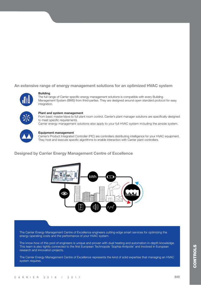
An extensive range of energy management solutions for an optimized HVAC system
Designed by Carrier Energy Management Centre of Excellence
kWh °C
The Carrier Energy Management Centre of Excellence engineers cutting-edge smart services for optimizing the energy operating costs and the performance of your HVAC system.
The know-how of this pool of engineers is unique and proven with dual heating and automation in-depth knowledge. This team is also tightly connected to the first European Technopole ‘Sophia-Antipolis’ and involved in European research and innovation projects.
The Carrier Energy Management Centre of Excellence represents the kind of solid expertise that managing an HVAC system requires.

850
CONTROLS
C A R R I E R 2 0 1 6 / 2 0 1 7
Carrier Thermal Energy Storage systemIn a global context affected by a continuous increase of electricity prices and the
challenge of reducing our environment impact, energy must be saved and controlled.
For energy demand management and sustainable approach to intelligent buildings,
Carrier proposes the Thermal Energy Storage technology (TES) by latent heat.
Carrier Thermal Energy Storage key benefits
Solution concept
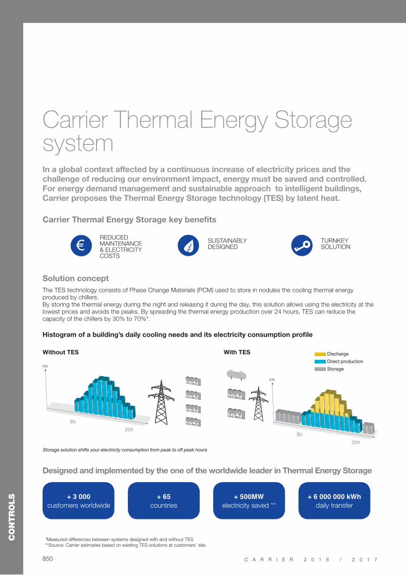
The TES technology consists of Phase Change Materials (PCM) used to store in nodules the cooling thermal energy produced by chillers. By storing the thermal energy during the night and releasing it during the day, this solution allows using the electricity at the lowest prices and avoids the peaks. By spreading the thermal energy production over 24 hours, TES can reduce the capacity of the chillers by 30% to 70%*.
Designed and implemented by the one of the worldwide leader in Thermal Energy Storage
Histogram of a building’s daily cooling needs and its electricity consumption profile
€
+ 3 000
customers worldwide
+ 65
countries
+ 500MW
electricity saved **
+ 6 000 000 kWh
daily transfer
8h
8h
20h
20h
Discharge
Direct production
Storage
Without TES With TES
REDUCED MAINTENANCE & ELECTRICITY COSTS
SUSTAINABLY DESIGNED
TURNKEY SOLUTION
*Measured differences between systems designed with and without TES
**Source: Carrier estimates based on existing TES solutions at customers’ site.
851
CONTROLS
C A R R I E R 2 0 1 6 / 2 0 1 7
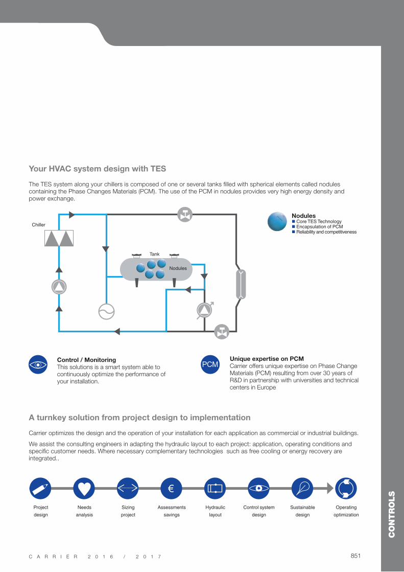
A turnkey solution from project design to implementation
Carrier optimizes the design and the operation of your installation for each application as commercial or industrial buildings.
We assist the consulting engineers in adapting the hydraulic layout to each project: application, operating conditions and specific customer needs. Where necessary complementary technologies such as free cooling or energy recovery are integrated..
Your HVAC system design with TES
The TES system along your chillers is composed of one or several tanks filled with spherical elements called nodules containing the Phase Changes Materials (PCM). The use of the PCM in nodules provides very high energy density and power exchange.
Project
design
Needs
analysis
Sizing
project
Assessments
savings
Hydraulic
layout
Control system
design
Sustainable
design
Operating
optimization
€
Nodules Core TES Technology Encapsulation of PCM Reliability and competitiveness
Control / Monitoring
This solutions is a smart system able to continuously optimize the performance of your installation.
Unique expertise on PCM
Carrier offers unique expertise on Phase Change Materials (PCM) resulting from over 30 years of R&D in partnership with universities and technical centers in Europe
Chiller
Tank
Nodules
PCM

852
CONTROLS
C A R R I E R 2 0 1 6 / 2 0 1 7
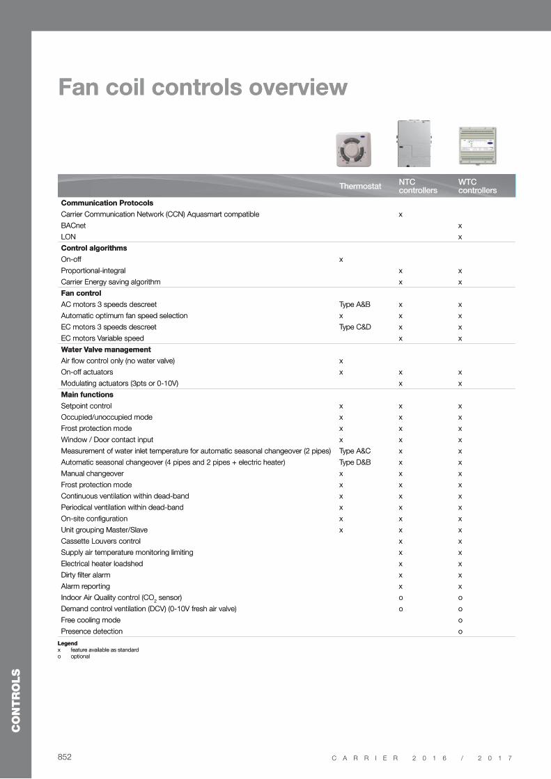
Fan coil controls overview
ThermostatNTC controllers
WTC controllers
Communication Protocols
Carrier Communication Network (CCN) Aquasmart compatible x
BACnet x
LON x
Control algorithms
On-off x
Proportional-integral x x
Carrier Energy saving algorithm x x
Fan control
AC motors 3 speeds descreet Type A&B x x
Automatic optimum fan speed selection x x x
EC motors 3 speeds descreet Type C&D x x
EC motors Variable speed x x
Water Valve management
Air flow control only (no water valve) x
On-off actuators x x x
Modulating actuators (3pts or 0-10V) x x
Main functions
Setpoint control x x x
Occupied/unoccupied mode x x x
Frost protection mode x x x
Window / Door contact input x x x
Measurement of water inlet temperature for automatic seasonal changeover (2 pipes) Type A&C x x
Automatic seasonal changeover (4 pipes and 2 pipes + electric heater) Type D&B x x
Manual changeover x x x
Frost protection mode x x x
Continuous ventilation within dead-band x x x
Periodical ventilation within dead-band x x x
On-site configuration x x x
Unit grouping Master/Slave x x x
Cassette Louvers control x x
Supply air temperature monitoring limiting x x
Electrical heater loadshed x x
Dirty filter alarm x x
Alarm reporting x x
Indoor Air Quality control (CO2 sensor) o o
Demand control ventilation (DCV) (0-10V fresh air valve) o o
Free cooling mode o
Presence detection o
Legend
x feature available as standardo optional

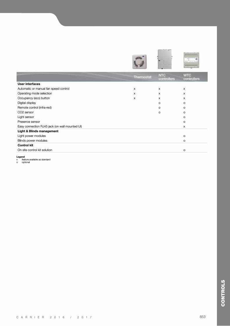
853
CONTROLS
C A R R I E R 2 0 1 6 / 2 0 1 7
Legend
x feature available as standardo optional
ThermostatNTC controllers
WTC controllers
User interfaces
Automatic or manual fan speed control x x x
Operating mode selection x x x
Occupancy (eco) button x x x
Digital display o o
Remote control (infra-red) o o
CO2 sensor o o
Light sensor o
Presence sensor o
Easy connection RJ45 jack (on wall mounted UI) x
Light & Blinds management
Light power modules o
Blinds power modules o
Control kit
On site control kit solution o

854
CONTROLS
C A R R I E R 2 0 1 6 / 2 0 1 7
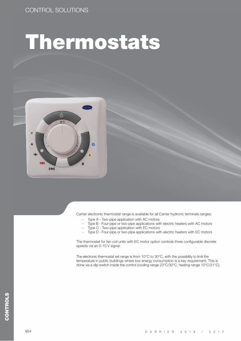
Thermostats
CONTROL SOLUTIONS
Carrier electronic thermostat range is available for all Carrier hydronic terminals ranges:
- Type A - Two-pipe application with AC motors - Type B - Four-pipe or two-pipe applications with electric heaters with AC motors - Type C - Two-pipe application with EC motors - Type D - Four-pipe or two-pipe applications with electric heaters with EC motors
The thermostat for fan coil units with EC motor option controls three configurable discrete speeds via an 0-10 V signal.
The electronic thermostat set range is from 10°C to 30°C, with the possibility to limit the temperature in public buildings where low energy consumption is a key requirement. This is done via a dip-switch inside the control (cooling range 23°C/30°C, heating range 10°C/21°C).

855
CONTROLS
C A R R I E R 2 0 1 6 / 2 0 1 7
Features and advantages Auto fan: the control automatically sets the fan speed. If
the room temperature is far from the set point, high fan speed is selected. As the room temperature approaches the desired value, the fan speed decreases to the minimum speed.
Automatic changeover from cooling to heating mode, based on the water temperature, ensures that the ideal room temperature is maintained.
Remote changeover - automatic changeover from cooling to heating mode, based on the remote signal from the monitoring system.
Frost protection keeps the room temperature above a minimum level.
Booster heating control optimisation (with electric heater option): with the water temperature below 30°C the system will be in heat demand mode and the electric heater is the only available heating source. If the water temperature is above 35°C the system will be in booster heating mode, energising water valve and electric heater together. This function is deactivated if the water temperature is above 45°C (the electric heater will be de-energised).
Energy saving when the room is unoccupied, without the need to switch off the unit. If the energy-saving button is pressed, the actual set point will be modified as follows, without changing the position of the set point selection knob: ± 4 K.
LED intensity (offices or light commercial applications) - 10 seconds after the last user interface use all LEDs are reduced in intensity. To avoid disturbing hotel guests, the thermostat can be configured from “Night Mode” to “Dark Mode”: 10 seconds after the last user interface use, all LEDs are switched off.
Air sampling: with no fan request and the air sampling jumper in ON position, the control performs the air sampling function. The air in the room is moved, thermal stratification is reduced for a more reliable ambient temperature reading.
Continuous fan (no fan request and continuous fan jumper ON): the control selects the fan speed, regardless of thermal station conditions. With fan in auto fan mode and control not in the demand phase, the fan permanently runs at low speed.
External contact: A high voltage input signal for external contact is present. If the contact is activated, device behaviour depends on its configuration on site:
- Presence detection energy saving mode is activated, room temperature is raised by 4 K in cooling mode and reduced by 4 K in heating mode.
- Window contact: in OFF mode (window open), all outputs are disconnected (fan, valves, etc.) and only the frost protection function is active, if enabled.
CONTROL SOLUTIONS THERMOSTATS

856
CONTROLS
C A R R I E R 2 0 1 6 / 2 0 1 7
NTC controllers
CONTROL SOLUTIONS
Carrier offers one of the market’s most sophisticated and complete communicating controllers for hydronic fan coil ranges, the NTC controller, that is compatible with the full Carrier fan coil range.
For the customer and installer the same controller simplifies and eases installation and service operations whilst covering a wide range of hydronic system types and applications.
The controller can be applied and function as either a standalone control, as part of a larger CCN system application, or at the heart of a Aquasmart system functioning with the Aquasmart Touch Pilot System Manager.

857
CONTROLS
C A R R I E R 2 0 1 6 / 2 0 1 7
Network communication
Advanced functions
The NTC communicating con-troller can be connected on an RS 485 bus, using the Carrier Comfort Network (CCN) protocol.
Units equipped with the NTC controller can be part of the Aquasmart Evolution system.
Low Energy Consumption (LEC) variable speed control.
The NTC controller can drive the fan speed continuously within a configurable range for optimal thermal and acoustic comfort.
Hydronic control - The NTC controls both floating and fixed-point value actuator types (230 V on-off and 230 V three point).
Demand controller ventilation (DCV) - On fan coils equipped with CO
2 sensors and fresh air dampers,
the NTC controller can adjust the amount of fresh air admitted to the room, as required by the occupants.
IAQ management - The NTC controller can control all features related to Indoor Air Quality that are included in Carrier terminal fan coil units.
250
190
56
Carrier Room Conroller (CRC2)
Simplified User Interface (SUI)
Zone User Interface (ZUI)
Infrared Remote Control (IR2) and receiver
CONTROL SOLUTIONS NTC
858
CONTROLS
C A R R I E R 2 0 1 6 / 2 0 1 7
BA
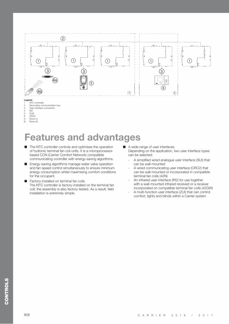
1
2
11 1 1
56
33 3
4a
4b
Legend
1 NTC controller2 Secondary communication bus3 User interface connection4 IR25 ZUI26 CRC2A Room AB Room B
Features and advantages The NTC controller controls and optimises the operation
of hydronic terminal fan coil units. It is a microprocessor-based CCN (Carrier Comfort Network) compatible communicating controller with energy-saving algorithms.
Energy-saving algorithms manage water valve operation and fan speed control simultaneously to ensure minimum energy consumption whilst maximising comfort conditions for the occupant.
Factory-installed on terminal fan coils The NTC controller is factory-installed on the terminal fan coil; the assembly is also factory-tested. As a result, field installation is extremely simple.
A wide range of user interfaces Depending on the application, two user interface types can be selected:
- A simplified wired analogue user interface (SUI) that can be wall-mounted
- A wired communicating user interface (CRC2) that can be wall-mounted or incorporated in compatible terminal fan coils (42N)
- An infrared user interface (IR2) for use together with a wall-mounted infrared received or a receiver incorporated on compatible terminal fan coils (42GW)
- A multi-function user interface (ZUI) that can control comfort, lights and blinds within a Carrier system
859
CONTROLS
C A R R I E R 2 0 1 6 / 2 0 1 7 859859859859859859859859859859859859859
CONTROL SOLUTIONS NTC
859

860
CONTROLS
C A R R I E R 2 0 1 6 / 2 0 1 7
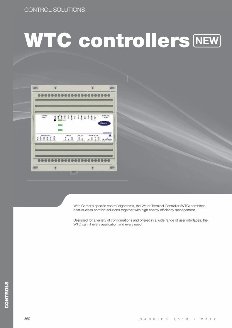
WTC controllers
CONTROL SOLUTIONS
With Carrier’s specific control algorithms, the Water Terminal Controller (WTC) combines best-in-class comfort solutions together with high energy efficiency management.
Designed for a variety of configurations and offered in a wide range of user interfaces, the WTC can fit every application and every need.
NEW

861
CONTROLS
C A R R I E R 2 0 1 6 / 2 0 1 7
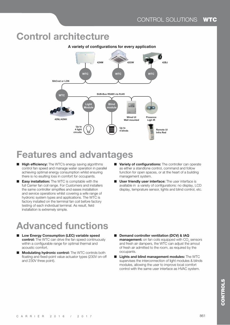
Features and advantages
Control architecture
Advanced functions
High efficiency: The WTC’s energy saving algorithms control fan speed and manage water operation in parallel achieving optimal energy consumption whilst ensuring there is no esulting loss in comfort for occupants.
Easy installation: The WTC is comptable with the full Carrier fan coil range. For Customers and installers the same controller simplifies and eases installation and service operations whilst covering a wife range of hydronic system types and applications. The WTC is factory installed on the terminal fan coil before factory testing of each individual terminal. As result, field installation is extremely simple.
Low Energy Consumption (LEC) variable speed control: The WTC can drive the fan speed continuously within a configurable range for optimal thermal and acoustic comfort.
Modulating hydronic control: The WTC controls both floating and fixed-point value actuator types (230V on-off and 230V three point).
Variety of configurations: The controller can operate as either a standlone control, command and follow function for open spaces, or at the heart of a building management system.
User friendly user interface: The user interface is avallable in a variety of configurations: no display, LCD display, temprature sensor, lights and blind control, etc.
Demand controller ventilation (DCV) & IAQ management: on fan coils equipped with CO
2 sensors
and fresh air dampers, the WTC can adjust the amout of fresh air admitted to the room, as required by the occupants.
Lights and blind management modules: The WTC supervises the interconnection of light modules & blinds modules, allowing the user to improve local comfort control with the same user interface as HVAC system.
CONTROL SOLUTIONS WTC
WTC
WTC
Light
Module
Blind
module
WTC WTC
42NL/42NH
SUB-Bus RS485 via RJ45
BACnet or LON
42NM 42GW 42BJ
Wired UI
Wall mounted
Presence
Ligh IR
Remote UI
Infra Red
Up to
4 blinds
Up to
4 light
circuits
42GW
862
CONTROLS
C A R R I E R 2 0 1 6 / 2 0 1 7
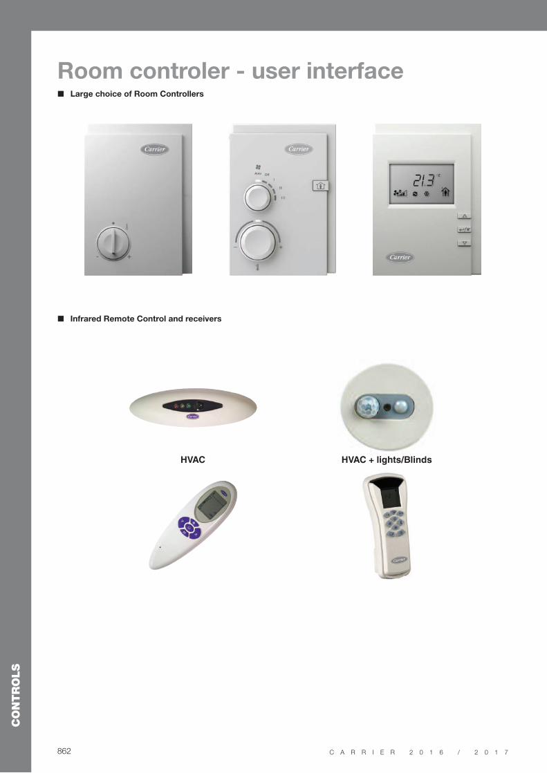
Infrared Remote Control and receivers
HVAC
Room controler - user interface Large choice of Room Controllers

863
CONTROLS
C A R R I E R 2 0 1 6 / 2 0 1 7
CONTROL SOLUTIONS WTC
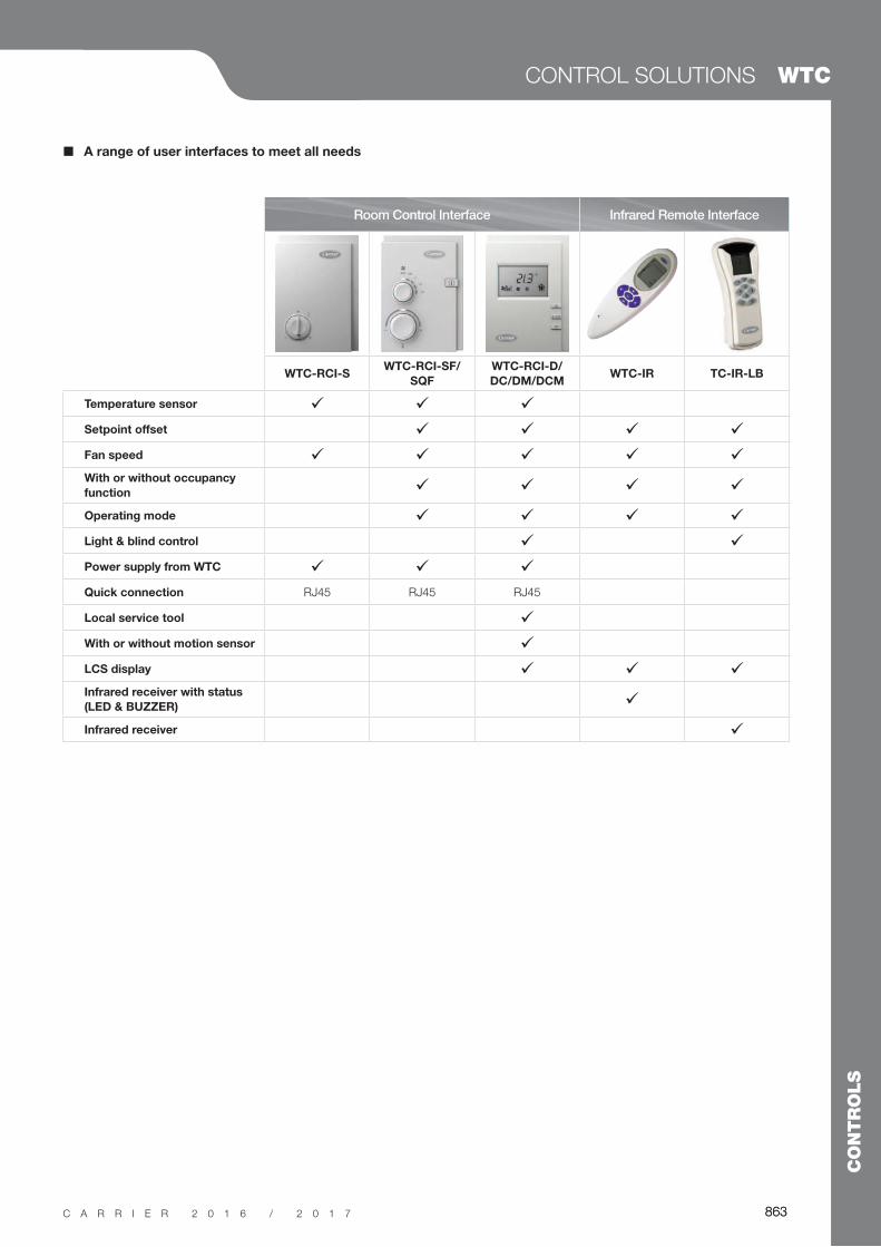
A range of user interfaces to meet all needs
Room Control Interface Infrared Remote Interface
WTC-RCI-SWTC-RCI-SF/
SQF
WTC-RCI-D/
DC/DM/DCMWTC-IR TC-IR-LB
Temperature sensor
Setpoint offset
Fan speed
With or without occupancy
function
Operating mode
Light & blind control
Power supply from WTC
Quick connection RJ45 RJ45 RJ45
Local service tool
With or without motion sensor
LCS display
Infrared receiver with status
(LED & BUZZER)
Infrared receiver
863

864
CONTROLS
C A R R I E R 2 0 1 6 / 2 0 1 7
Aquasmart
CONTROL SOLUTIONS
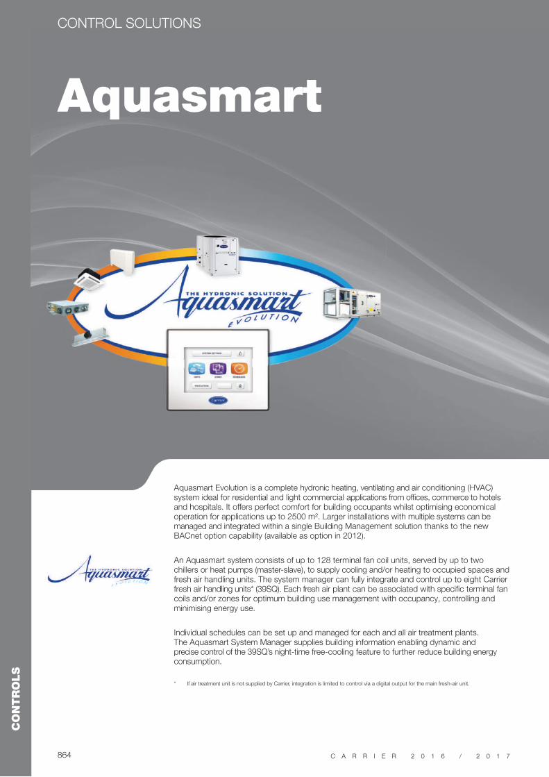
Aquasmart Evolution is a complete hydronic heating, ventilating and air conditioning (HVAC) system ideal for residential and light commercial applications from offices, commerce to hotels and hospitals. It offers perfect comfort for building occupants whilst optimising economical operation for applications up to 2500 m². Larger installations with multiple systems can be managed and integrated within a single Building Management solution thanks to the new BACnet option capability (available as option in 2012).
An Aquasmart system consists of up to 128 terminal fan coil units, served by up to two chillers or heat pumps (master-slave), to supply cooling and/or heating to occupied spaces and fresh air handling units. The system manager can fully integrate and control up to eight Carrier fresh air handling units* (39SQ). Each fresh air plant can be associated with specific terminal fan coils and/or zones for optimum building use management with occupancy, controlling and minimising energy use.
Individual schedules can be set up and managed for each and all air treatment plants. The Aquasmart System Manager supplies building information enabling dynamic and precise control of the 39SQ’s night-time free-cooling feature to further reduce building energy consumption.
* If air treatment unit is not supplied by Carrier, integration is limited to control via a digital output for the main fresh-air unit.
865
CONTROLS
C A R R I E R 2 0 1 6 / 2 0 1 7
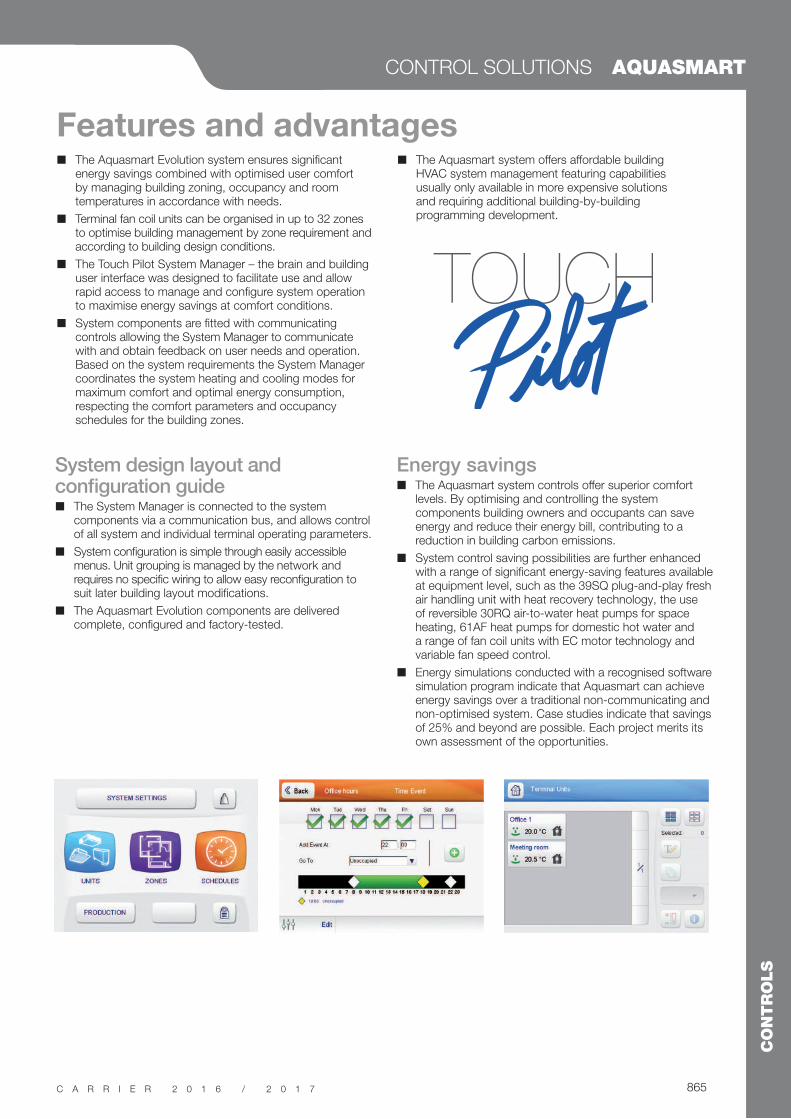
System design layout and configuration guide
The System Manager is connected to the system components via a communication bus, and allows control of all system and individual terminal operating parameters.
System configuration is simple through easily accessible menus. Unit grouping is managed by the network and requires no specific wiring to allow easy reconfiguration to suit later building layout modifications.
The Aquasmart Evolution components are delivered complete, configured and factory-tested.
Energy savings The Aquasmart system controls offer superior comfort
levels. By optimising and controlling the system components building owners and occupants can save energy and reduce their energy bill, contributing to a reduction in building carbon emissions.
System control saving possibilities are further enhanced with a range of significant energy-saving features available at equipment level, such as the 39SQ plug-and-play fresh air handling unit with heat recovery technology, the use of reversible 30RQ air-to-water heat pumps for space heating, 61AF heat pumps for domestic hot water and a range of fan coil units with EC motor technology and variable fan speed control.
Energy simulations conducted with a recognised software simulation program indicate that Aquasmart can achieve energy savings over a traditional non-communicating and non-optimised system. Case studies indicate that savings of 25% and beyond are possible. Each project merits its own assessment of the opportunities.
CONTROL SOLUTIONS AQUASMART
Features and advantages The Aquasmart Evolution system ensures significant
energy savings combined with optimised user comfort by managing building zoning, occupancy and room temperatures in accordance with needs.
Terminal fan coil units can be organised in up to 32 zones to optimise building management by zone requirement and according to building design conditions.
The Touch Pilot System Manager – the brain and building user interface was designed to facilitate use and allow rapid access to manage and configure system operation to maximise energy savings at comfort conditions.
System components are fitted with communicating controls allowing the System Manager to communicate with and obtain feedback on user needs and operation. Based on the system requirements the System Manager coordinates the system heating and cooling modes for maximum comfort and optimal energy consumption, respecting the comfort parameters and occupancy schedules for the building zones.
The Aquasmart system offers affordable building HVAC system management featuring capabilities usually only available in more expensive solutions and requiring additional building-by-building programming development.

866
CONTROLS
C A R R I E R 2 0 1 6 / 2 0 1 7
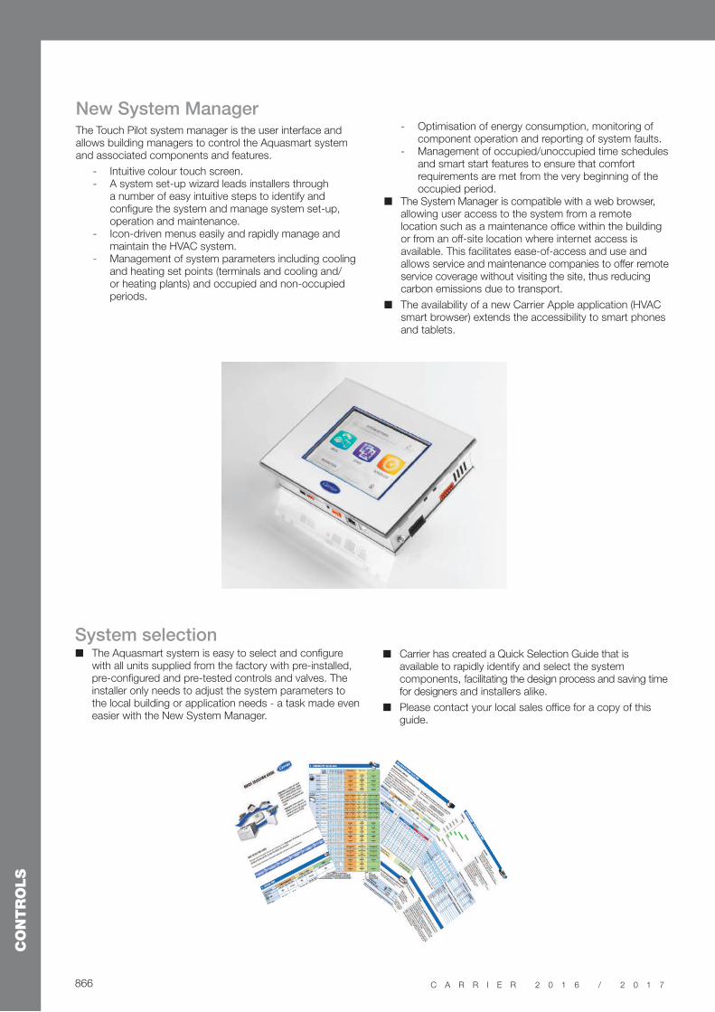
New System ManagerThe Touch Pilot system manager is the user interface and allows building managers to control the Aquasmart system and associated components and features.
- Intuitive colour touch screen. - A system set-up wizard leads installers through
a number of easy intuitive steps to identify and configure the system and manage system set-up, operation and maintenance.
- Icon-driven menus easily and rapidly manage and maintain the HVAC system.
- Management of system parameters including cooling and heating set points (terminals and cooling and/or heating plants) and occupied and non-occupied periods.
System selection The Aquasmart system is easy to select and configure
with all units supplied from the factory with pre-installed, pre-configured and pre-tested controls and valves. The installer only needs to adjust the system parameters to the local building or application needs - a task made even easier with the New System Manager.
- Optimisation of energy consumption, monitoring of component operation and reporting of system faults.
- Management of occupied/unoccupied time schedules and smart start features to ensure that comfort requirements are met from the very beginning of the occupied period.
The System Manager is compatible with a web browser, allowing user access to the system from a remote location such as a maintenance office within the building or from an off-site location where internet access is available. This facilitates ease-of-access and use and allows service and maintenance companies to offer remote service coverage without visiting the site, thus reducing carbon emissions due to transport.
The availability of a new Carrier Apple application (HVAC smart browser) extends the accessibility to smart phones and tablets.
Carrier has created a Quick Selection Guide that is available to rapidly identify and select the system components, facilitating the design process and saving time for designers and installers alike.
Please contact your local sales office for a copy of this guide.
867
CONTROLS
C A R R I E R 2 0 1 6 / 2 0 1 7
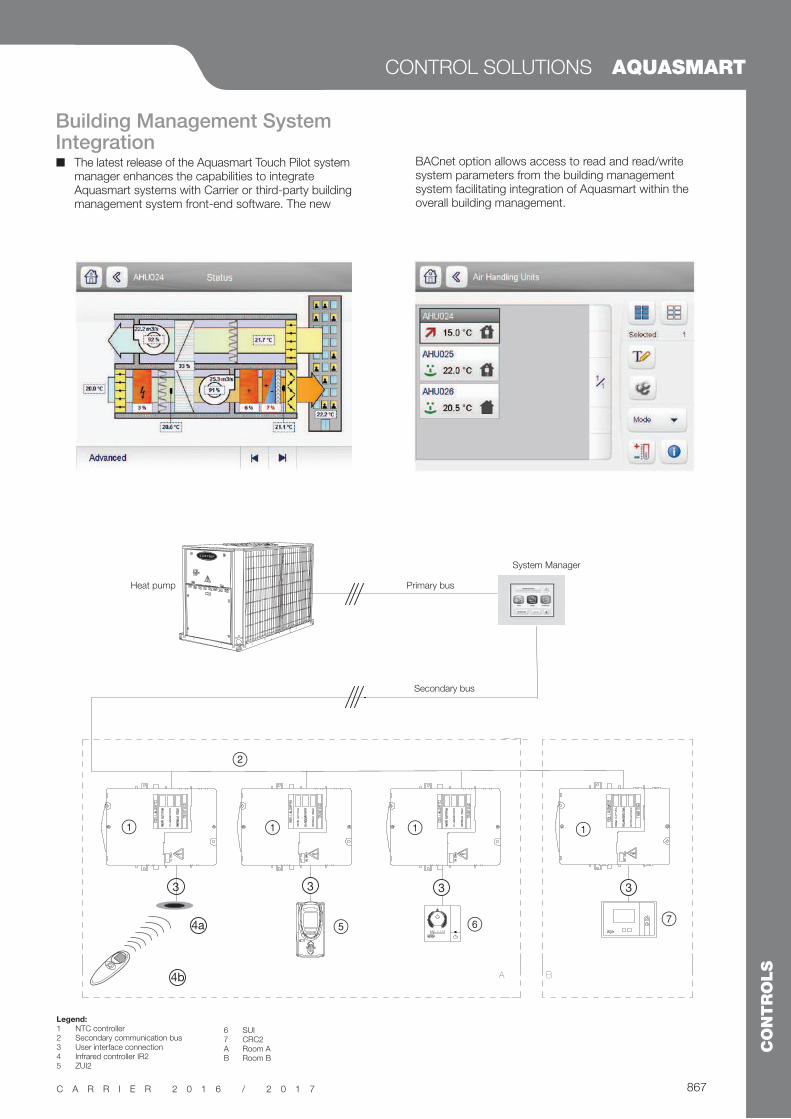
Building Management System Integration
The latest release of the Aquasmart Touch Pilot system manager enhances the capabilities to integrate Aquasmart systems with Carrier or third-party building management system front-end software. The new
Legend:
1 NTC controller2 Secondary communication bus3 User interface connection4 Infrared controller IR25 ZUI2
6 SUI7 CRC2A Room AB Room B
3
4a
4b
3 3 3
Primary bus
Secondary bus
System Manager
Heat pump
A B
CONTROL SOLUTIONS AQUASMART
BACnet option allows access to read and read/write system parameters from the building management system facilitating integration of Aquasmart within the overall building management.


848
CONTROLS
C A R R I E R 2 0 1 6 / 2 0 1 7
Carrier Energy Management solutionsCarrier Energy Management solutions provide end users with low energy, high
performance and enhanced indoor air quality and comfort.
These energy management solutions are designed and developed with the support of
engineers from Carrier Energy Management Centre of Excellence.
Their expertise ensure the solutions are fully tailored to meet the specific needs of each
customer.
Key advantages
Maximum energy efficiency and lower cost of
ownership
A highly monitored control system immediately lowers operating costs. By managing load shedding and equipment schedules, it can achieve annual energy savings of 15% to 35%*.
Scalability and flexibility
Carrier delivers a scalable and reliable automated control solution uniquely tailored to each business, based on an understanding of its specific needs.
Reliability
Carrier solutions reliably pilot equipment, maintaining peak functionality and thereby preventing unanticipated system and equipment failure.
Single accountability
Carrier designs, supplies, configures and maintains the installation and its operating system, providing customers with a single point of contact.
Optimal comfort
Automatic controls maintain optimal ambient conditions within a facility, for constant measured comfort for all occupants.
CARRIER ENERGY MANAGEMENT SOLUTIONS
Smart
services
for your HVAC system
LOW OPERATING COSTS HIGH PERFORMANCE ENHANCED COMFORT
*Source: Carrier estimates from German existing control installations.
849
CONTROLS
C A R R I E R 2 0 1 6 / 2 0 1 7
Building
The full range of Carrier specific energy management solutions is compatible with every Building Management System (BMS) from third-parties. They are designed around open standard protocol for easy integration.
Plant and system management
From basic master/slave to full plant room control, Carrier’s plant manager solutions are specifically designed to meet specific requirements.Carrier energy management solutions also apply to your full HVAC system including the airside system.
Equipment management
Carrier’s Product Integrated Controller (PIC) are controllers distributing intelligence for your HVAC equipment. They host and execute specific algorithms to enable interaction with Carrier plant controllers.
An extensive range of energy management solutions for an optimized HVAC system
Designed by Carrier Energy Management Centre of Excellence
kWh °C
The Carrier Energy Management Centre of Excellence engineers cutting-edge smart services for optimizing the energy operating costs and the performance of your HVAC system.
The know-how of this pool of engineers is unique and proven with dual heating and automation in-depth knowledge. This team is also tightly connected to the first European Technopole ‘Sophia-Antipolis’ and involved in European research and innovation projects.
The Carrier Energy Management Centre of Excellence represents the kind of solid expertise that managing an HVAC system requires.
850
CONTROLS
C A R R I E R 2 0 1 6 / 2 0 1 7
Carrier Thermal Energy Storage systemIn a global context affected by a continuous increase of electricity prices and the
challenge of reducing our environment impact, energy must be saved and controlled.
For energy demand management and sustainable approach to intelligent buildings,
Carrier proposes the Thermal Energy Storage technology (TES) by latent heat.
Carrier Thermal Energy Storage key benefits
Solution concept
The TES technology consists of Phase Change Materials (PCM) used to store in nodules the cooling thermal energy produced by chillers. By storing the thermal energy during the night and releasing it during the day, this solution allows using the electricity at the lowest prices and avoids the peaks. By spreading the thermal energy production over 24 hours, TES can reduce the capacity of the chillers by 30% to 70%*.
Designed and implemented by the one of the worldwide leader in Thermal Energy Storage
Histogram of a building’s daily cooling needs and its electricity consumption profile
€
+ 3 000
customers worldwide
+ 65
countries
+ 500MW
electricity saved **
+ 6 000 000 kWh
daily transfer
8h
8h
20h
20h
Discharge
Direct production
Storage
Without TES With TES
REDUCED MAINTENANCE & ELECTRICITY COSTS
SUSTAINABLY DESIGNED
TURNKEY SOLUTION
*Measured differences between systems designed with and without TES
**Source: Carrier estimates based on existing TES solutions at customers’ site.

851
CONTROLS
C A R R I E R 2 0 1 6 / 2 0 1 7
A turnkey solution from project design to implementation
Carrier optimizes the design and the operation of your installation for each application as commercial or industrial buildings.
We assist the consulting engineers in adapting the hydraulic layout to each project: application, operating conditions and specific customer needs. Where necessary complementary technologies such as free cooling or energy recovery are integrated..
Your HVAC system design with TES
The TES system along your chillers is composed of one or several tanks filled with spherical elements called nodules containing the Phase Changes Materials (PCM). The use of the PCM in nodules provides very high energy density and power exchange.
Project
design
Needs
analysis
Sizing
project
Assessments
savings
Hydraulic
layout
Control system
design
Sustainable
design
Operating
optimization
€
Nodules Core TES Technology Encapsulation of PCM Reliability and competitiveness
Control / Monitoring
This solutions is a smart system able to continuously optimize the performance of your installation.
Unique expertise on PCM
Carrier offers unique expertise on Phase Change Materials (PCM) resulting from over 30 years of R&D in partnership with universities and technical centers in Europe
Chiller
Tank
Nodules
PCM
852
CONTROLS
C A R R I E R 2 0 1 6 / 2 0 1 7
Fan coil controls overview
ThermostatNTC controllers
WTC controllers
Communication Protocols
Carrier Communication Network (CCN) Aquasmart compatible x
BACnet x
LON x
Control algorithms
On-off x
Proportional-integral x x
Carrier Energy saving algorithm x x
Fan control
AC motors 3 speeds descreet Type A&B x x
Automatic optimum fan speed selection x x x
EC motors 3 speeds descreet Type C&D x x
EC motors Variable speed x x
Water Valve management
Air flow control only (no water valve) x
On-off actuators x x x
Modulating actuators (3pts or 0-10V) x x
Main functions
Setpoint control x x x
Occupied/unoccupied mode x x x
Frost protection mode x x x
Window / Door contact input x x x
Measurement of water inlet temperature for automatic seasonal changeover (2 pipes) Type A&C x x
Automatic seasonal changeover (4 pipes and 2 pipes + electric heater) Type D&B x x
Manual changeover x x x
Frost protection mode x x x
Continuous ventilation within dead-band x x x
Periodical ventilation within dead-band x x x
On-site configuration x x x
Unit grouping Master/Slave x x x
Cassette Louvers control x x
Supply air temperature monitoring limiting x x
Electrical heater loadshed x x
Dirty filter alarm x x
Alarm reporting x x
Indoor Air Quality control (CO2 sensor) o o
Demand control ventilation (DCV) (0-10V fresh air valve) o o
Free cooling mode o
Presence detection o
Legend
x feature available as standardo optional
853
CONTROLS
C A R R I E R 2 0 1 6 / 2 0 1 7
Legend
x feature available as standardo optional
ThermostatNTC controllers
WTC controllers
User interfaces
Automatic or manual fan speed control x x x
Operating mode selection x x x
Occupancy (eco) button x x x
Digital display o o
Remote control (infra-red) o o
CO2 sensor o o
Light sensor o
Presence sensor o
Easy connection RJ45 jack (on wall mounted UI) x
Light & Blinds management
Light power modules o
Blinds power modules o
Control kit
On site control kit solution o
Legend
x feature available as standardo optional
ThermostatNTC controllers
WTC controllers
User interfaces
Automatic or manual fan speed control x x x
Operating mode selection x x x
Occupancy (eco) button x x x
Digital display o o
Remote control (infra-red) o o
CO2 sensor o o
Light sensor o
Presence sensor o
Easy connection RJ45 jack (on wall mounted UI) x
Light & Blinds management
Light power modules o
Blinds power modules o
Control kit
On site control kit solution o
854
CONTROLS
C A R R I E R 2 0 1 6 / 2 0 1 7
Thermostats
CONTROL SOLUTIONS
Carrier electronic thermostat range is available for all Carrier hydronic terminals ranges:
- Type A - Two-pipe application with AC motors - Type B - Four-pipe or two-pipe applications with electric heaters with AC motors - Type C - Two-pipe application with EC motors - Type D - Four-pipe or two-pipe applications with electric heaters with EC motors
The thermostat for fan coil units with EC motor option controls three configurable discrete speeds via an 0-10 V signal.
The electronic thermostat set range is from 10°C to 30°C, with the possibility to limit the temperature in public buildings where low energy consumption is a key requirement. This is done via a dip-switch inside the control (cooling range 23°C/30°C, heating range 10°C/21°C).

855
CONTROLS
C A R R I E R 2 0 1 6 / 2 0 1 7
Features and advantages Auto fan: the control automatically sets the fan speed. If
the room temperature is far from the set point, high fan speed is selected. As the room temperature approaches the desired value, the fan speed decreases to the minimum speed.
Automatic changeover from cooling to heating mode, based on the water temperature, ensures that the ideal room temperature is maintained.
Remote changeover - automatic changeover from cooling to heating mode, based on the remote signal from the monitoring system.
Frost protection keeps the room temperature above a minimum level.
Booster heating control optimisation (with electric heater option): with the water temperature below 30°C the system will be in heat demand mode and the electric heater is the only available heating source. If the water temperature is above 35°C the system will be in booster heating mode, energising water valve and electric heater together. This function is deactivated if the water temperature is above 45°C (the electric heater will be de-energised).
Energy saving when the room is unoccupied, without the need to switch off the unit. If the energy-saving button is pressed, the actual set point will be modified as follows, without changing the position of the set point selection knob: ± 4 K.
LED intensity (offices or light commercial applications) - 10 seconds after the last user interface use all LEDs are reduced in intensity. To avoid disturbing hotel guests, the thermostat can be configured from “Night Mode” to “Dark Mode”: 10 seconds after the last user interface use, all LEDs are switched off.
Air sampling: with no fan request and the air sampling jumper in ON position, the control performs the air sampling function. The air in the room is moved, thermal stratification is reduced for a more reliable ambient temperature reading.
Continuous fan (no fan request and continuous fan jumper ON): the control selects the fan speed, regardless of thermal station conditions. With fan in auto fan mode and control not in the demand phase, the fan permanently runs at low speed.
External contact: A high voltage input signal for external contact is present. If the contact is activated, device behaviour depends on its configuration on site:
- Presence detection energy saving mode is activated, room temperature is raised by 4 K in cooling mode and reduced by 4 K in heating mode.
- Window contact: in OFF mode (window open), all outputs are disconnected (fan, valves, etc.) and only the frost protection function is active, if enabled.
CONTROL SOLUTIONS THERMOSTATS

856
CONTROLS
C A R R I E R 2 0 1 6 / 2 0 1 7
NTC controllers
CONTROL SOLUTIONS
Carrier offers one of the market’s most sophisticated and complete communicating controllers for hydronic fan coil ranges, the NTC controller, that is compatible with the full Carrier fan coil range.
For the customer and installer the same controller simplifies and eases installation and service operations whilst covering a wide range of hydronic system types and applications.
The controller can be applied and function as either a standalone control, as part of a larger CCN system application, or at the heart of a Aquasmart system functioning with the Aquasmart Touch Pilot System Manager.

857
CONTROLS
C A R R I E R 2 0 1 6 / 2 0 1 7
Network communication
Advanced functions
The NTC communicating con-troller can be connected on an RS 485 bus, using the Carrier Comfort Network (CCN) protocol.
Units equipped with the NTC controller can be part of the Aquasmart Evolution system.
Low Energy Consumption (LEC) variable speed control.
The NTC controller can drive the fan speed continuously within a configurable range for optimal thermal and acoustic comfort.
Hydronic control - The NTC controls both floating and fixed-point value actuator types (230 V on-off and 230 V three point).
Demand controller ventilation (DCV) - On fan coils equipped with CO
2 sensors and fresh air dampers,
the NTC controller can adjust the amount of fresh air admitted to the room, as required by the occupants.
IAQ management - The NTC controller can control all features related to Indoor Air Quality that are included in Carrier terminal fan coil units.
250
190
56
Carrier Room Conroller (CRC2)
Simplified User Interface (SUI)
Zone User Interface (ZUI)
Infrared Remote Control (IR2) and receiver
CONTROL SOLUTIONS NTC

858
CONTROLS
C A R R I E R 2 0 1 6 / 2 0 1 7
BA
1
2
11 1 1
56
33 3
4a
4b
Legend
1 NTC controller2 Secondary communication bus3 User interface connection4 IR25 ZUI26 CRC2A Room AB Room B
Features and advantages The NTC controller controls and optimises the operation
of hydronic terminal fan coil units. It is a microprocessor-based CCN (Carrier Comfort Network) compatible communicating controller with energy-saving algorithms.
Energy-saving algorithms manage water valve operation and fan speed control simultaneously to ensure minimum energy consumption whilst maximising comfort conditions for the occupant.
Factory-installed on terminal fan coils The NTC controller is factory-installed on the terminal fan coil; the assembly is also factory-tested. As a result, field installation is extremely simple.
A wide range of user interfaces Depending on the application, two user interface types can be selected:
- A simplified wired analogue user interface (SUI) that can be wall-mounted
- A wired communicating user interface (CRC2) that can be wall-mounted or incorporated in compatible terminal fan coils (42N)
- An infrared user interface (IR2) for use together with a wall-mounted infrared received or a receiver incorporated on compatible terminal fan coils (42GW)
- A multi-function user interface (ZUI) that can control comfort, lights and blinds within a Carrier system
860
CONTROLS
C A R R I E R 2 0 1 6 / 2 0 1 7
WTC controllers
CONTROL SOLUTIONS
With Carrier’s specific control algorithms, the Water Terminal Controller (WTC) combines best-in-class comfort solutions together with high energy efficiency management.
Designed for a variety of configurations and offered in a wide range of user interfaces, the WTC can fit every application and every need.
NEW
861
CONTROLS
C A R R I E R 2 0 1 6 / 2 0 1 7
Features and advantages
Control architecture
Advanced functions
High efficiency: The WTC’s energy saving algorithms control fan speed and manage water operation in parallel achieving optimal energy consumption whilst ensuring there is no esulting loss in comfort for occupants.
Easy installation: The WTC is comptable with the full Carrier fan coil range. For Customers and installers the same controller simplifies and eases installation and service operations whilst covering a wife range of hydronic system types and applications. The WTC is factory installed on the terminal fan coil before factory testing of each individual terminal. As result, field installation is extremely simple.
Low Energy Consumption (LEC) variable speed control: The WTC can drive the fan speed continuously within a configurable range for optimal thermal and acoustic comfort.
Modulating hydronic control: The WTC controls both floating and fixed-point value actuator types (230V on-off and 230V three point).
Variety of configurations: The controller can operate as either a standlone control, command and follow function for open spaces, or at the heart of a building management system.
User friendly user interface: The user interface is avallable in a variety of configurations: no display, LCD display, temprature sensor, lights and blind control, etc.
Demand controller ventilation (DCV) & IAQ management: on fan coils equipped with CO
2 sensors
and fresh air dampers, the WTC can adjust the amout of fresh air admitted to the room, as required by the occupants.
Lights and blind management modules: The WTC supervises the interconnection of light modules & blinds modules, allowing the user to improve local comfort control with the same user interface as HVAC system.
CONTROL SOLUTIONS WTC
WTC
WTC
Light
Module
Blind
module
WTC WTC
42NL/42NH
SUB-Bus RS485 via RJ45
BACnet or LON
42NM 42GW 42BJ
Wired UI
Wall mounted
Presence
Ligh IR
Remote UI
Infra Red
Up to
4 blinds
Up to
4 light
circuits
42GW

862
CONTROLS
C A R R I E R 2 0 1 6 / 2 0 1 7
Infrared Remote Control and receivers
HVAC
Room controler - user interface Large choice of Room Controllers
863
CONTROLS
C A R R I E R 2 0 1 6 / 2 0 1 7
CONTROL SOLUTIONS WTC
A range of user interfaces to meet all needs
Room Control Interface Infrared Remote Interface
WTC-RCI-SWTC-RCI-SF/
SQF
WTC-RCI-D/
DC/DM/DCMWTC-IR TC-IR-LB
Temperature sensor
Setpoint offset
Fan speed
With or without occupancy
function
Operating mode
Light & blind control
Power supply from WTC
Quick connection RJ45 RJ45 RJ45
Local service tool
With or without motion sensor
LCS display
Infrared receiver with status
(LED & BUZZER)
Infrared receiver
863
864
CONTROLS
C A R R I E R 2 0 1 6 / 2 0 1 7
Aquasmart
CONTROL SOLUTIONS
Aquasmart Evolution is a complete hydronic heating, ventilating and air conditioning (HVAC) system ideal for residential and light commercial applications from offices, commerce to hotels and hospitals. It offers perfect comfort for building occupants whilst optimising economical operation for applications up to 2500 m². Larger installations with multiple systems can be managed and integrated within a single Building Management solution thanks to the new BACnet option capability (available as option in 2012).
An Aquasmart system consists of up to 128 terminal fan coil units, served by up to two chillers or heat pumps (master-slave), to supply cooling and/or heating to occupied spaces and fresh air handling units. The system manager can fully integrate and control up to eight Carrier fresh air handling units* (39SQ). Each fresh air plant can be associated with specific terminal fan coils and/or zones for optimum building use management with occupancy, controlling and minimising energy use.
Individual schedules can be set up and managed for each and all air treatment plants. The Aquasmart System Manager supplies building information enabling dynamic and precise control of the 39SQ’s night-time free-cooling feature to further reduce building energy consumption.
* If air treatment unit is not supplied by Carrier, integration is limited to control via a digital output for the main fresh-air unit.

865
CONTROLS
C A R R I E R 2 0 1 6 / 2 0 1 7
System design layout and configuration guide
The System Manager is connected to the system components via a communication bus, and allows control of all system and individual terminal operating parameters.
System configuration is simple through easily accessible menus. Unit grouping is managed by the network and requires no specific wiring to allow easy reconfiguration to suit later building layout modifications.
The Aquasmart Evolution components are delivered complete, configured and factory-tested.
Energy savings The Aquasmart system controls offer superior comfort
levels. By optimising and controlling the system components building owners and occupants can save energy and reduce their energy bill, contributing to a reduction in building carbon emissions.
System control saving possibilities are further enhanced with a range of significant energy-saving features available at equipment level, such as the 39SQ plug-and-play fresh air handling unit with heat recovery technology, the use of reversible 30RQ air-to-water heat pumps for space heating, 61AF heat pumps for domestic hot water and a range of fan coil units with EC motor technology and variable fan speed control.
Energy simulations conducted with a recognised software simulation program indicate that Aquasmart can achieve energy savings over a traditional non-communicating and non-optimised system. Case studies indicate that savings of 25% and beyond are possible. Each project merits its own assessment of the opportunities.
CONTROL SOLUTIONS AQUASMART
Features and advantages The Aquasmart Evolution system ensures significant
energy savings combined with optimised user comfort by managing building zoning, occupancy and room temperatures in accordance with needs.
Terminal fan coil units can be organised in up to 32 zones to optimise building management by zone requirement and according to building design conditions.
The Touch Pilot System Manager – the brain and building user interface was designed to facilitate use and allow rapid access to manage and configure system operation to maximise energy savings at comfort conditions.
System components are fitted with communicating controls allowing the System Manager to communicate with and obtain feedback on user needs and operation. Based on the system requirements the System Manager coordinates the system heating and cooling modes for maximum comfort and optimal energy consumption, respecting the comfort parameters and occupancy schedules for the building zones.
The Aquasmart system offers affordable building HVAC system management featuring capabilities usually only available in more expensive solutions and requiring additional building-by-building programming development.
866
CONTROLS
C A R R I E R 2 0 1 6 / 2 0 1 7
New System ManagerThe Touch Pilot system manager is the user interface and allows building managers to control the Aquasmart system and associated components and features.
- Intuitive colour touch screen. - A system set-up wizard leads installers through
a number of easy intuitive steps to identify and configure the system and manage system set-up, operation and maintenance.
- Icon-driven menus easily and rapidly manage and maintain the HVAC system.
- Management of system parameters including cooling and heating set points (terminals and cooling and/or heating plants) and occupied and non-occupied periods.
System selection The Aquasmart system is easy to select and configure
with all units supplied from the factory with pre-installed, pre-configured and pre-tested controls and valves. The installer only needs to adjust the system parameters to the local building or application needs - a task made even easier with the New System Manager.
- Optimisation of energy consumption, monitoring of component operation and reporting of system faults.
- Management of occupied/unoccupied time schedules and smart start features to ensure that comfort requirements are met from the very beginning of the occupied period.
The System Manager is compatible with a web browser, allowing user access to the system from a remote location such as a maintenance office within the building or from an off-site location where internet access is available. This facilitates ease-of-access and use and allows service and maintenance companies to offer remote service coverage without visiting the site, thus reducing carbon emissions due to transport.
The availability of a new Carrier Apple application (HVAC smart browser) extends the accessibility to smart phones and tablets.
Carrier has created a Quick Selection Guide that is available to rapidly identify and select the system components, facilitating the design process and saving time for designers and installers alike.
Please contact your local sales office for a copy of this guide.

867
CONTROLS
C A R R I E R 2 0 1 6 / 2 0 1 7
Building Management System Integration
The latest release of the Aquasmart Touch Pilot system manager enhances the capabilities to integrate Aquasmart systems with Carrier or third-party building management system front-end software. The new
Legend:
1 NTC controller2 Secondary communication bus3 User interface connection4 Infrared controller IR25 ZUI2
6 SUI7 CRC2A Room AB Room B
3
4a
4b
3 3 3
Primary bus
Secondary bus
System Manager
Heat pump
A B
CONTROL SOLUTIONS AQUASMART
BACnet option allows access to read and read/write system parameters from the building management system facilitating integration of Aquasmart within the overall building management.