Embed Size (px)
Citation preview
Appendix 6
Information requested by the NPWS on emission monitoring data Carranstown, Co. Meath, comparative data from similar waste-to-energy incinerator facilities, Effects of hazardous compounds and information on plant start-up and shut-down procedures

Appendix 6. Additional information requested by the NPWS.
This appendix provide additional information on issues raised by the NPWS during consultation meetings. It addresses the following issues.
Information on plant start-up and shut-down procedures including frequency of start-up and shut-down, and emergency response procedures (Requested at the NPWS meeting, May 2015). (Appendix 6)
Information on air emission monitoring data from Indaver’s plant at Carranstown, Co Meath. (Requested at the NPWS meeting, May 2015). (Appendix 6).
Comparative data from similar waste-to-energy incinerator facilities (Point 3 of DAU letter). This information is provided in (Appendix 6).
Effects of hazardous compounds (Point 8 of DAU letter). This is addressed in Appendix 6.
1. Plant start-up and shut-down procedures and frequency of start-up and shut-down, and emergency response procedures with particular reference to the paper by Wang (2007)
Furnace Start Up And Planned Shut Down Procedure The start-up and shut down of the furnace will be carefully controlled, in accordance with standard operating procedures. The procedures will be developed in detail prior to the commissioning of the furnace. There is a maximum of two planned shutdowns per year and can be up to 5 in total, each of these is a controlled shutdown and start up as outlined in the procedure below
The start-up sequence for the furnace line will be as follows:
The computerised control system for the line will be started up, which will mean that measurements and interlock systems will be in operation.
Utilities for the plant such as water, electricity, instrument air, the firewater system and safety systems will then be started up.
Monitoring of some of these utilities will be carried out, as certain conditions such as firewater availability must be satisfied before the start-up procedure can commence.
Peripheral equipment, such as the equipment to supply chemicals to the plant, to receive the process steam from the plant and the stack emissions monitoring equipment will then be started up.
After verification of process parameters such as liquid levels, pressures, steam cycle etc., and adjustment as necessary, the flue gas cleaning systems will be started up.
The ID-fan will commence running and pre-ventilation of the line for a pre-set time period will occur.
The oil-fired burners, to initiate the combustion in the furnace, will be started up and the flue gas temperature will be raised to 850°C at a gradient of 50°C per hour.
Once the temperature in the furnace has stabilised, the supply of waste will then commence and oil firing will be stopped when the process is steady.
The planned shut down sequence for a furnace line will be as follows:
The waste supply to the furnace will be shut off
To ensure complete combustion of the waste remaining in the furnace, the oil burners will be re-started to ensure that a temperature of 850°C, as appropriate, will be maintained for a period of up to 1 hour or until all the waste is incinerated.
The ID fan of the flue gas cleaning system will remain operating to ensure that the flue gases will be treated to the emission limits during the operation.
The furnace will then be allowed to cool down to a temperature of 200°C at a gradient of 50°C per hour (a period of circa 13 hours) which will be controlled by supplementary firing.
The furnace line will have stopped incinerating waste for a number of hours, there will be no waste remaining in the furnace and consequently there will be no flue gases to be cleaned. Once the temperature at the stack is sufficiently low at approximately 60°C, the flue gas cleaning systems will be stopped.
Some utilities to the plant such as instrument air, etc. and the majority of the peripheral equipment will be shut-off.
Other utilities such as electrical supply will continue operating as they will be required even when the plant is shut down.
Emergency Shutdown Procedure The emergency shut down will bring the incinerator line to a safe status. The main objectives of the emergency shut down procedure are as follows:
To shut down the plant safely, avoiding injury to staff or damage to equipment
to minimise emissions
to protect equipment from damage caused by temperatures which are too high.
The experience of the operators of Indaver’s plants in Meath/Belgium is that an emergency shut down is not a frequent occurrence.
In case of failure of electrical power supply, the plant will switch over to island mode and power itself through the turbine. The plant will reduce in load and remain in a stable condition. If the turbine trips in this condition then the motors and equipment required for the emergency shut down will be powered by the emergency generator.
The emergency shut down will be automatically executed in two steps.
Step 1 is the waste burn out. As soon as the emergency shut down commences all waste supply will be stopped immediately. The ID-fan will be stopped. The water supply to the spray reactor will be stopped. An emergency supply may be provided for use in the spray reactor, if the temperature of the flue gases exceeds 250ºC. This option will be decided at detailed design stage.
The injection of activated carbon/clay and lime will stop and may be reactivated by the operator, manually, once the reason for the shut down is known and it is determined that there will be no risk in doing so.
The inertia of the ID-fan will ensure that the flue gases will continue to be evacuated through the flue gas cleaning systems, prior to the start-up of the ID-fan via the auxiliary motor, which will be powered by the emergency generator.
In the grate furnace, air to burn out the residual waste will be drawn into the furnace because the inertia of the ID-fan will maintain under-pressure in the furnace. During this period the flue gas flow will drop quickly to less than 20 % of the normal flow. At this stage the waste in the furnace will be almost completely burned. Only a few bigger waste parts will still be smouldering. The auxiliary motor (with gear box) of the ID-fan will then engage and continue
on partial load. The power of this motor will be sufficient to evacuate the remaining flue gas through the flue gas cleaning system.
Step 2 is the cooling step. Once there is no more waste in the furnace, the ID fan will continue to pull air through the furnace boiler for a controlled cool down to protect the refractory and boiler from to rapid a cool down which could lead to mechanical failure. The ID fan can then be stopped once the plant is below 60° C.
During any emergency shutdown, while there is waste in the furnace all the flue gases pass through the gas cleaning system and are emitted through the stack. As stated above, the ID Fan is kept operating during the shutdown by means of an auxiliary motor and an emergency generator. In the event of an emergency shutdown and failure of the emergency generator the inertia of the ID Fan would continue to draw the flue gases through the gas cleaning system for an initial period. It is highly unlikely that there would be both an emergency shutdown and a failure of the emergency generator at the same time.
While step 1 of the shutdown sequence is underway, the combustion gases will continue to pass through the flue gas cleaning systems and the bag house filter and particulates will be removed as efficiently as during normal operations (except in the case of catastrophic failure of the baghouse). The activated carbon/clay/lime mixture present on the sleeves of the bag house filter will continue to remove heavy metals, dioxins, HCI, HF and SO2 from the combustion gases.
The fixed installed emissions monitoring equipment located on the stack will continue to monitor the emissions from the stack. In the event of loss of mains power, the monitoring equipment will be supplied with electricity from the Uninterruptible Power Supply (UPS) and emergency generator
A risk analysis will be carried out on this procedure during the detailed design phase of the project (in the form of a Hazard and Operability Study) during which the final details of the procedure will be decided.
Quick stop incineration
During the operation of the plant there can be conditions that force a scenario called quick stop incineration. These conditions are for example when the pressure increases in the furnace. If this occurs, the first stage alarm will indicate to the operator that the pressure is increasing and if no action is taken by the operator, then the second stage alarm will increase the ID fan speed to reduce the pressure. If this does not reduce the pressure then waste feeding will be stopped and the air supplied to the furnace for combustion will be reduced or stopped and the ID fan will reduce to ensure that the waste on the grate is still combusting in a controlled manor. The operator can then resolve the issue that lead to the quick stop incineration conditions and return the plant to normal operating conditions.
The fixed installed emissions monitoring equipment located on the stack will continue to monitor the emissions from the stack during this time.
Assessment of the paper by Wang (2007)
The paper ‘Influence of start-up on PCDD/F emission of incinerators’, Wang et al (2007) highlights the potential for dioxin production during a cold start up of an incinerator. It is noted that the paper does not provide information explaining the process conditions and process set-up details. More specifically the paper does not provide details on the following:
year of construction of the plant
secondary air mixing effect,
residence time of flue gas at minimum 850°C,
combustion temperature,
calorific value of the waste,
the equipment setup,
information on boiler cleaning,
quantity of activated carbon used,
temperature in the flue cleaning,
combustion air pre-heating or the presence of a bypass valve for flue gas over the dioxin abatement step.
As a lot of the potential reasons for poor control of dioxin levels are ignored in the article, it is problematic to accurately assess the validity of the paper. It is correct that in the absence of control measures, the cold start-up of the incinerator is favorable for dioxin production. It is also correct that some materials absorb dioxins and release dioxins (memory effect). However these effects are effectively negated by the control measures as detailed below. These measures ensure that excess emissions of dioxins do not occur during start-up procedures.
1. The number of cold starts is limited to a minimum. The maintenance strategy is focused on a high plant availability. This is only possible with a low frequency of unscheduled shut downs and cold start-ups.
2. Cold startup is done through the bag filter. The filter cake is not removed or a filter cake is applied in case of new filter bags. It contains activated carbon and this abates dioxins. The flue gas cleaning residue is mainly re-circulated in order to get a better use of the carbon and lime. The carbon dosing can be started if necessary to ensure there is no bypass of the dioxin abatement step during a cold start. Hence the downstream equipment is not exposed to increased dioxin concentrations and the memory effect does not occur.
3. The combustion chamber is state of the art. Geometry and flow patterns are also designed to limit undesirable conditions for burnout at cold start up.
4. Fuel burners are selected with a low CO and NOx production in cold start conditions. This reduces also the amount of dioxin precursors.
5. The bag filter is pre-coated with a lime/carbon/residue mixture prior to cold startup. The carbon concentration is higher than during normal operation with waste.
6. The plant is designed and operated with a big margin below the dioxin emission limit. The limit is 0.1 ng TEQ / Nm3. The plant is operated with an emission of less than 10 % of this emission limit in order to absorb unwanted events or suboptimal process conditions.
7. Materials that absorb dioxins and release it as memory effect are avoided. 8. The boiler has fixed installed cleaning devices. Before a shut down extra cleaning
cycles will be executed. During the shutdown the boiler will be cleaned manually if the fouling is abnormal.
2. Data from other European sites
Indaver and the project team met representatives of the National Parks and Wildlife Service (NPWS) in April 2015. At the meeting, the NPWS representative suggested that data on the monitoring of the effects of waste to energy plants on nearby special protection areas would be useful. Indaver/ARUP carried out a desktop review to identify incinerators in proximity to SPAs in Europe. A recent International Solid Waste Association report provided information on over 472 plants in 18 European countries (Austria, Belgium, Czech Republic, Denmark, Finland, France, Germany, Hungary, Italy, Ireland, Netherland, Norway, Portugal, Slovakia, Spain, Sweden, Switzerland and United Kingdom). Each of the plants is treating more than 100,000 tonnes per annum of municipal solid waste.
A closer look identified over 60 of these that were within 15km of special area of conservation (SPA) (See Table 1). In Belgium, France and the UK examples of incinerators can be found located within less than 0.5km of an SPA and the results suggest that proximity to an SPA does not, in general, create a significant barrier to permission being granted to incinerators in proximity to SPAs. Indaver contacted representatives of the waste-to-energy industry in the UK, Ireland, Germany, Belgium and The Netherlands but found no evidence for a biomonitoring programme instigated by a specific incinerator. The general consensus was that such programmes are not required due to the low emission levels and the low potential for impacts.
Indaver specifically contacted the following waste to energy facilities: (a) Runcorn municipal waste incinerator (Cheshire, UK), within 300m of the Mersey Estuary SPA; (b) Marchwood Energy from Waste Facility (Southampton, UK), within 1km of the Solent and Southampton Water SPA; (c) Exeter Energy from Waste facility (Devon, UK), within 2km of the Exe River SPA; (d) La Collete non-hazardous waste incinerator facility (Jersey, UK), near to the South East coast of Jersey Ramsar site. It is Indaver’s understanding that the facilities noted above do not have ecological data on the impact of operating incinerators collated to support the conclusion of the Appropriate Assessment No specific bio-monitoring programmes to monitor the effects of the operations on the nearby SPA are implemented by these plants. All of the incinerators proposals were subject to a full assessment as part of the planning and licencing procedures.
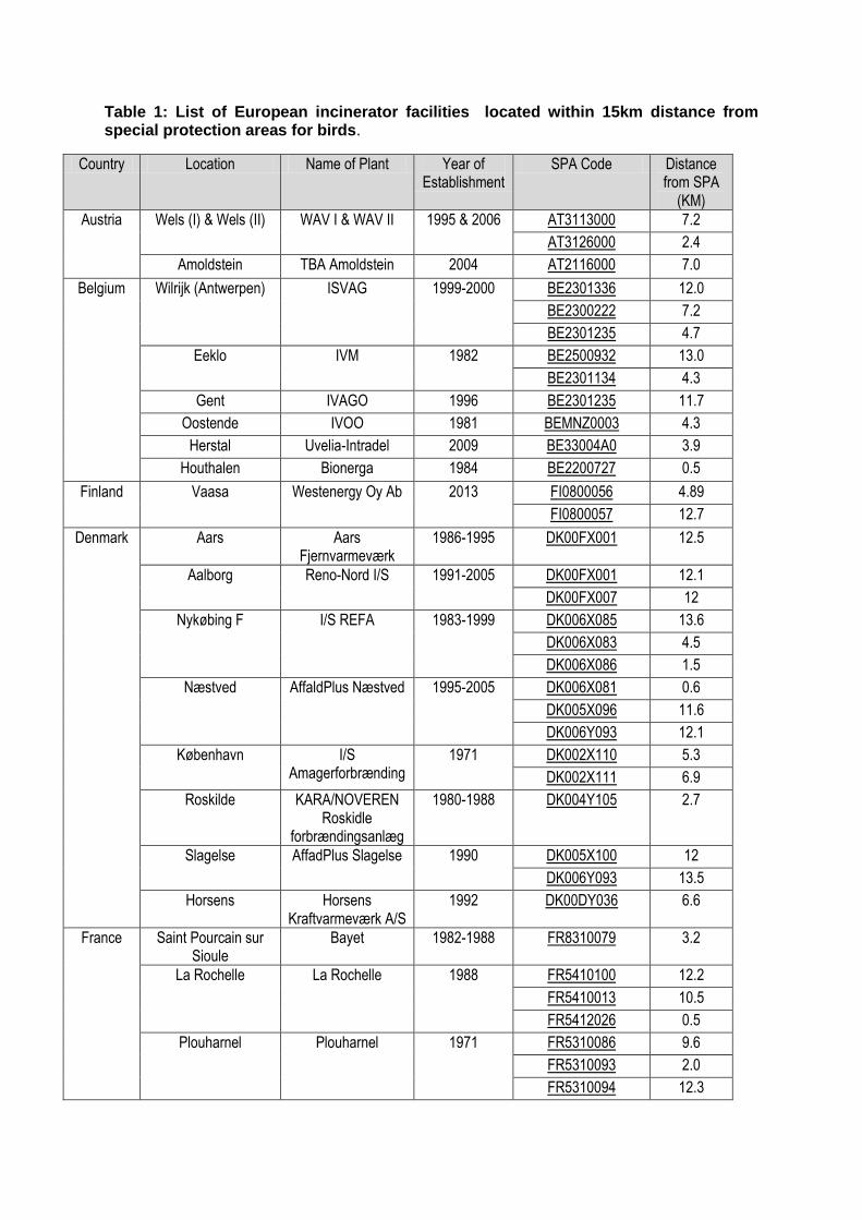
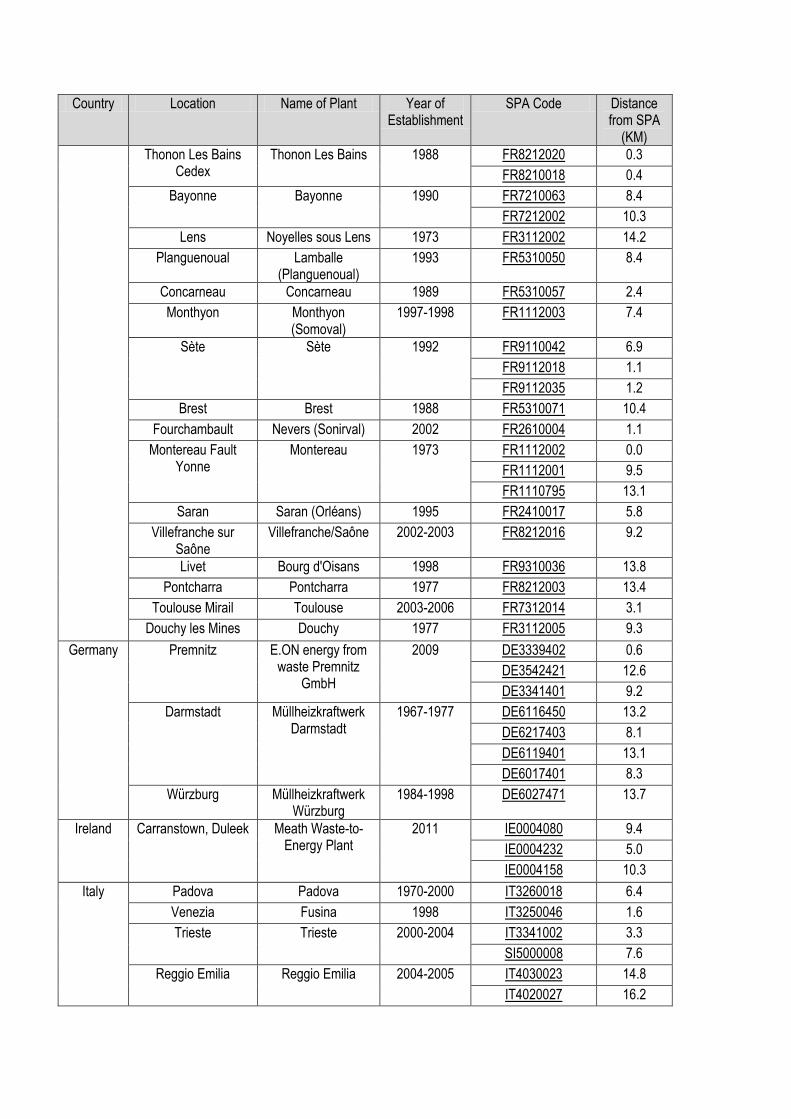
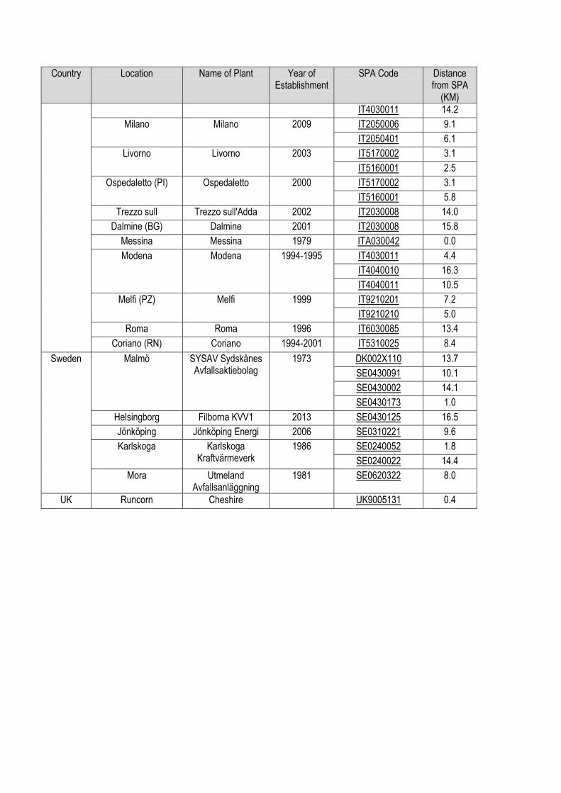
Table 1: List of European incinerator facilities located within 15km distance from special protection areas for birds.
Country Location Name of Plant Year of Establishment
SPA Code Distance from SPA
(KM)
Austria Wels (I) & Wels (II) WAV I & WAV II 1995 & 2006 AT3113000 7.2
AT3126000 2.4
Amoldstein TBA Amoldstein 2004 AT2116000 7.0
Belgium Wilrijk (Antwerpen) ISVAG 1999-2000 BE2301336 12.0
BE2300222 7.2
BE2301235 4.7
Eeklo IVM 1982 BE2500932 13.0
BE2301134 4.3
Gent IVAGO 1996 BE2301235 11.7
Oostende IVOO 1981 BEMNZ0003 4.3
Herstal Uvelia-Intradel 2009 BE33004A0 3.9
Houthalen Bionerga 1984 BE2200727 0.5
Finland Vaasa Westenergy Oy Ab 2013 FI0800056 4.89
FI0800057 12.7
Denmark Aars Aars Fjernvarmeværk
1986-1995 DK00FX001 12.5
Aalborg Reno-Nord I/S 1991-2005 DK00FX001 12.1
DK00FX007 12
Nykøbing F I/S REFA 1983-1999 DK006X085 13.6
DK006X083 4.5
DK006X086 1.5
Næstved AffaldPlus Næstved 1995-2005 DK006X081 0.6
DK005X096 11.6
DK006Y093 12.1
København I/S Amagerforbrænding
1971 DK002X110 5.3
DK002X111 6.9
Roskilde KARA/NOVEREN Roskidle
forbrændingsanlæg
1980-1988 DK004Y105 2.7
Slagelse AffadPlus Slagelse 1990 DK005X100 12
DK006Y093 13.5
Horsens Horsens Kraftvarmeværk A/S
1992 DK00DY036 6.6
France Saint Pourcain sur Sioule
Bayet 1982-1988 FR8310079 3.2
La Rochelle La Rochelle 1988 FR5410100 12.2
FR5410013 10.5
FR5412026 0.5
Plouharnel Plouharnel 1971 FR5310086 9.6
FR5310093 2.0
FR5310094 12.3
Country Location Name of Plant Year of Establishment
SPA Code Distance from SPA
(KM)
Thonon Les Bains Cedex
Thonon Les Bains 1988 FR8212020 0.3
FR8210018 0.4
Bayonne Bayonne 1990 FR7210063 8.4
FR7212002 10.3
Lens Noyelles sous Lens 1973 FR3112002 14.2
Planguenoual Lamballe (Planguenoual)
1993 FR5310050 8.4
Concarneau Concarneau 1989 FR5310057 2.4
Monthyon Monthyon (Somoval)
1997-1998 FR1112003 7.4
Sète Sète 1992 FR9110042 6.9
FR9112018 1.1
FR9112035 1.2
Brest Brest 1988 FR5310071 10.4
Fourchambault Nevers (Sonirval) 2002 FR2610004 1.1
Montereau Fault Yonne
Montereau 1973 FR1112002 0.0
FR1112001 9.5
FR1110795 13.1
Saran Saran (Orléans) 1995 FR2410017 5.8
Villefranche sur Saône
Villefranche/Saône 2002-2003 FR8212016 9.2
Livet Bourg d'Oisans 1998 FR9310036 13.8
Pontcharra Pontcharra 1977 FR8212003 13.4
Toulouse Mirail Toulouse 2003-2006 FR7312014 3.1
Douchy les Mines Douchy 1977 FR3112005 9.3
Germany Premnitz E.ON energy from waste Premnitz
GmbH
2009 DE3339402 0.6
DE3542421 12.6
DE3341401 9.2
Darmstadt Müllheizkraftwerk Darmstadt
1967-1977 DE6116450 13.2
DE6217403 8.1
DE6119401 13.1
DE6017401 8.3
Würzburg Müllheizkraftwerk Würzburg
1984-1998 DE6027471 13.7
Ireland Carranstown, Duleek Meath Waste-to-Energy Plant
2011 IE0004080 9.4
IE0004232 5.0
IE0004158 10.3
Italy Padova Padova 1970-2000 IT3260018 6.4
Venezia Fusina 1998 IT3250046 1.6
Trieste Trieste 2000-2004 IT3341002 3.3
SI5000008 7.6
Reggio Emilia Reggio Emilia 2004-2005 IT4030023 14.8
IT4020027 16.2
Country Location Name of Plant Year of Establishment
SPA Code Distance from SPA
(KM)
IT4030011 14.2
Milano Milano 2009 IT2050006 9.1
IT2050401 6.1
Livorno Livorno 2003 IT5170002 3.1
IT5160001 2.5
Ospedaletto (PI) Ospedaletto 2000 IT5170002 3.1
IT5160001 5.8
Trezzo sull Trezzo sull'Adda 2002 IT2030008 14.0
Dalmine (BG) Dalmine 2001 IT2030008 15.8
Messina Messina 1979 ITA030042 0.0
Modena Modena 1994-1995 IT4030011 4.4
IT4040010 16.3
IT4040011 10.5
Melfi (PZ) Melfi 1999 IT9210201 7.2
IT9210210 5.0
Roma Roma 1996 IT6030085 13.4
Coriano (RN) Coriano 1994-2001 IT5310025 8.4
Sweden Malmö SYSAV Sydskånes Avfallsaktiebolag
1973 DK002X110 13.7
SE0430091 10.1
SE0430002 14.1
SE0430173 1.0
Helsingborg Filborna KVV1 2013 SE0430125 16.5
Jönköping Jönköping Energi 2006 SE0310221 9.6
Karlskoga Karlskoga Kraftvärmeverk
1986 SE0240052 1.8
SE0240022 14.4
Mora Utmeland Avfallsanläggning
1981 SE0620322 8.0
UK Runcorn Cheshire UK9005131 0.4
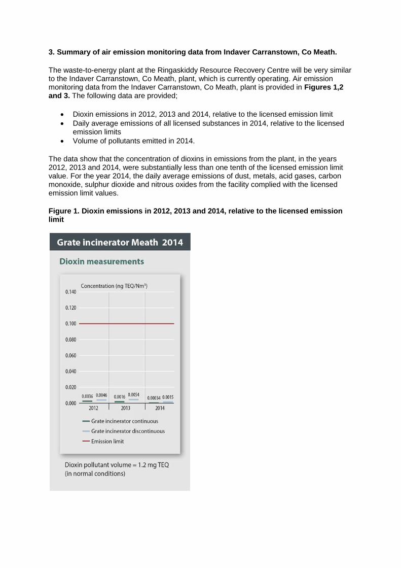
3. Summary of air emission monitoring data from Indaver Carranstown, Co Meath.
The waste-to-energy plant at the Ringaskiddy Resource Recovery Centre will be very similar to the Indaver Carranstown, Co Meath, plant, which is currently operating. Air emission monitoring data from the Indaver Carranstown, Co Meath, plant is provided in Figures 1,2 and 3. The following data are provided;
Dioxin emissions in 2012, 2013 and 2014, relative to the licensed emission limit
Daily average emissions of all licensed substances in 2014, relative to the licensed emission limits
Volume of pollutants emitted in 2014.
The data show that the concentration of dioxins in emissions from the plant, in the years 2012, 2013 and 2014, were substantially less than one tenth of the licensed emission limit value. For the year 2014, the daily average emissions of dust, metals, acid gases, carbon monoxide, sulphur dioxide and nitrous oxides from the facility complied with the licensed emission limit values.
Figure 1. Dioxin emissions in 2012, 2013 and 2014, relative to the licensed emission limit
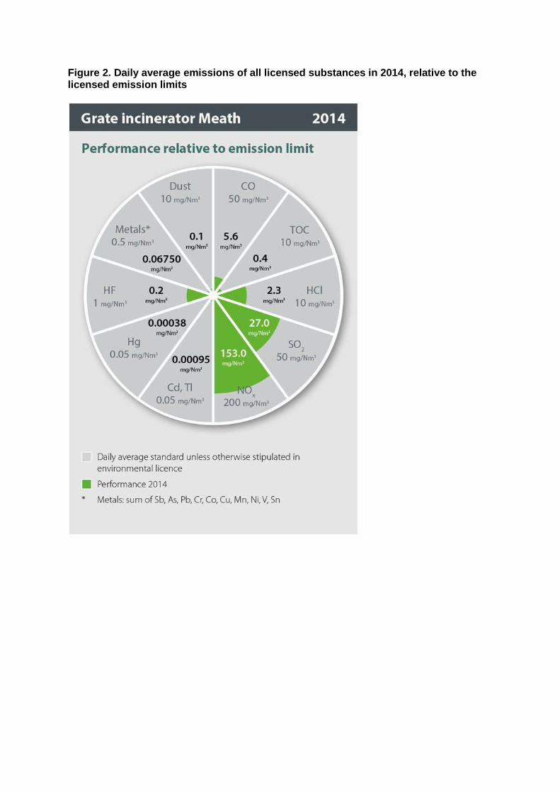
Figure 2. Daily average emissions of all licensed substances in 2014, relative to the licensed emission limits
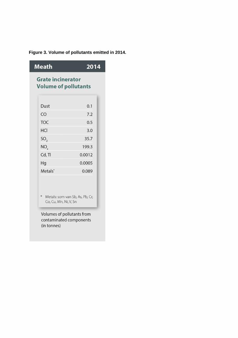
Figure 3. Volume of pollutants emitted in 2014.
4. Potential Effects of hazardous compounds
Grate furnaces are used for the destruction of a wide variety of waste streams and are a well-recognised, robust and established technology for these purposes. Waste is burned on the grate for a period of 1 hour approximately, and the resultant flue gases must maintain a temperature of 850°C for a minimum of 2 seconds after the last injection of air to ensure complete combustion of any volatiles and unburned flue gas components. In reality the flue gas temperatures range from 850°C to 1,200°C in the combustion zone above the grate. These temperatures ensure destruction of organics and other flue gas components. Consequently a hazardous substance that is fed into the furnace does not come out unchanged as the same hazardous substance, either in the residues or in the exhaust gases. In the furnace the hazardous substance is oxidised which means it under goes a chemical reaction and is converted into one or more different substances with different properties. These different substances are removed in the ash or flue gas cleaning residues and a very small quantity is discharged to the air in the exhaust gases. Compounds such as dioxins which form after combustion is complete (and at lower temperature windows in the boiler of around 450°C) are removed by the injection of activated carbon/clay.