Embed Size (px)
Citation preview
Carpet Waste Gasification:
Technical, Economic, Environmental Assessment for Carpet Mills
ENGR4300
University of Tennessee at Chattanooga
May 6, 2011
Project Team:
Jordan Buecker
Christopher Burns
Katharine Davis
Hemali Dholakia
Kevin O’Brien
Table of Contents
1 Executive Summary 1
2 Introduction 2
3 Process Flow Diagrams and Descriptions 2
3.1 Air Gasifier ..................................................................................................................................... 2
3.2 Oxygen Gasifier ............................................................................................................................. 3
3.3 Steam Gasifier ............................................................................................................................... 4
4 Components 6
4.1 Cyclone Separator ......................................................................................................................... 7
4.2 Gas Turbine ................................................................................................................................... 7
4.2.1 Fuel Conditioning for Gas Turbine ........................................................................................ 7
5 Material Balances 8
6 Environmental Analysis 11
7 Economic Analysis 12
8 Discussion 13
9 Conclusions 13
10 Recommendations 13
11 References 13

1
Executive Summary
2
Introduction
With the cost of fuel ever increasing and the current push towards “going green,” new and
innovative methods must be developed to reclaim and recycle usable energy from previously untapped
resources.
Post-consumer carpet waste (PCC) is carbon based material and can be gasified to produce
syngas. With a heat of combustion similar to coal, syngas enables much usable energy to be reclaimed
from the carpet rather than losing that energy to a landfill.
It is our goal to provide a means for carpet manufactures to reclaim some of the energy in the
carpet that comes back to them for consumer recycle/disposal. The method chosen to accomplish this is
gasification and production of synthesis gas (syngas).
Three main types of gasifiers exist and are explored in this report. The gasifiers explored are: air
gasifier, oxygen gasifier and steam gasifier. Process flow diagrams and descriptions are shown in section
3.
Process Flow Diagrams and Descriptions
Air Gasifier
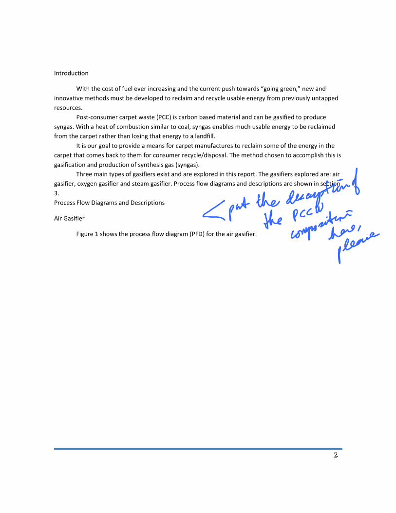
Figure 1 shows the process flow diagram (PFD) for the air gasifier.
3
Figure 1: PFD for air gasifier
As presented in Figure 3, the air and carpet waste enter the gasifier where they react to produce
syngas and calcium oxide (CaO). The CaO/syngas mixture then enters a cyclone separator where they
are separated. The CaO is stored for later disposal and the syngas is sent to a combustion/boiler unit for
the production of steam.
Oxygen Gasifier
The oxygen gasifier operations identically to the air gasifier except there is need to have nearly
pure oxygen as a reactant rather than air. Figure 2 shows the PFD for an oxygen gasifier.
4
Figure 2: Oxygen gasifier
Steam Gasifier
The steam gasifier uses steam as the reactant with carpet. The syngas produced by this
gasification process contains methane and has a higher heating value than syngas produced by air and
oxygen gasification. Because of the higher heating value, the syngas can be used to power a gas turbine
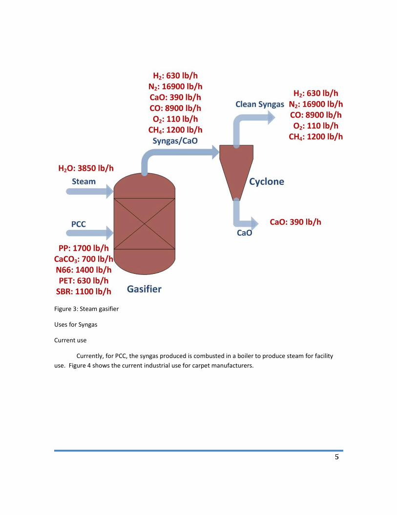
for production of electricity. Figure 3 shows the PFD for the steam gasifier.
This image cannot currently be displayed.
5
Figure 3: Steam gasifier
Uses for Syngas
Current use
Currently, for PCC, the syngas produced is combusted in a boiler to produce steam for facility
use. Figure 4 shows the current industrial use for carpet manufacturers.
6
Figure 4: Current PPC-produced syngas usage.
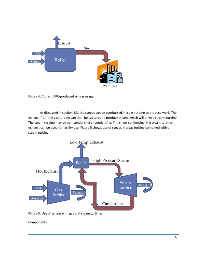
As discussed in section 3.3, the syngas can be combusted in a gas turbine to produce work. The
exhaust from the gas turbine can then be captured to produce steam, which will drive a stream turbine.
The steam turbine may be non-condensing or condensing. If it is non-condensing, the steam turbine
exhaust can be used for facility use. Figure 5 shows use of syngas in a gas turbine combined with a
steam turbine.
Figure 5: Use of syngas with gas and steam turbines
Components
7
Components described in Figures 1-5 are described in this section.
Cyclone Separator
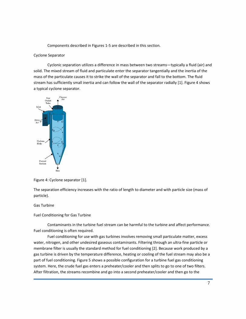
Cyclonic separation utilizes a difference in mass between two streams—typically a fluid (air) and
solid. The mixed stream of fluid and particulate enter the separator tangentially and the inertia of the
mass of the particulate causes it to strike the wall of the separator and fall to the bottom. The fluid
stream has sufficiently small inertia and can follow the wall of the separator radially [1]. Figure 4 shows
a typical cyclone separator.
Figure 4: Cyclone separator [1].
The separation efficiency increases with the ratio of length to diameter and with particle size (mass of
particle).
Gas Turbine
Fuel Conditioning for Gas Turbine
Contaminants in the turbine fuel stream can be harmful to the turbine and affect performance.
Fuel conditioning is often required.
Fuel conditioning for use with gas turbines involves removing small particulate matter, excess
water, nitrogen, and other undesired gaseous contaminants. Filtering through an ultra-fine particle or
membrane filter is usually the standard method for fuel conditioning [2]. Because work produced by a
gas turbine is driven by the temperature difference, heating or cooling of the fuel stream may also be a
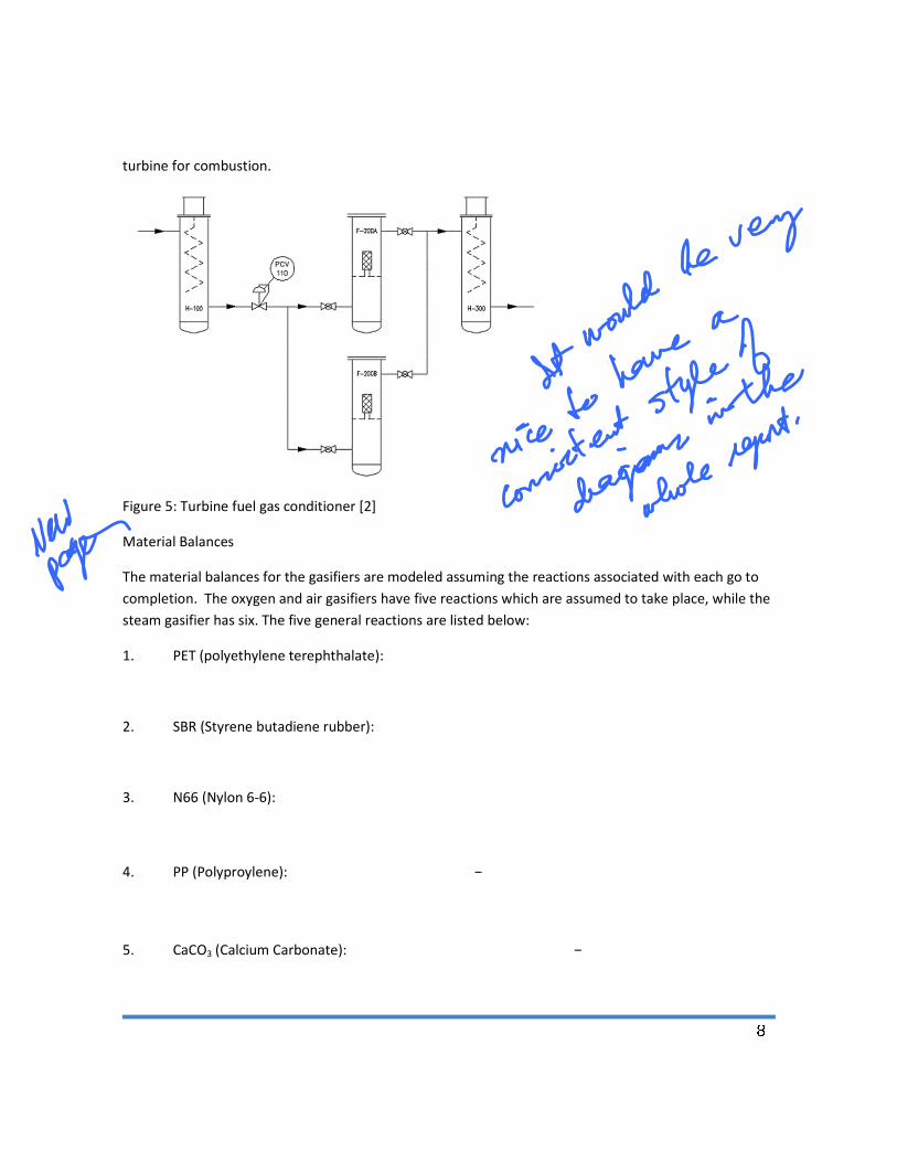
part of fuel conditioning. Figure 5 shows a possible configuration for a turbine fuel gas conditioning
system. Here, the crude fuel gas enters a preheater/cooler and then splits to go to one of two filters.
After filtration, the streams recombine and go into a second preheater/cooler and then go to the
8
turbine for combustion.
Figure 5: Turbine fuel gas conditioner [2]
Material Balances
The material balances for the gasifiers are modeled assuming the reactions associated with each go to
completion. The oxygen and air gasifiers have five reactions which are assumed to take place, while the
steam gasifier has six. The five general reactions are listed below:
1. PET (polyethylene terephthalate):
2. SBR (Styrene butadiene rubber):
3. N66 (Nylon 6-6):
4. PP (Polyproylene):
5. CaCO3 (Calcium Carbonate):
9
The additional reaction for the steam gasifier is the reaction of the carbon monoxide with the steam
(water) present to produce methane and carbon dioxide.
6. Methane Production: 2��� 2��� → ��� � ���
Although some carbon monoxide (part of the syngas) is used up to produce methane, the syngas which
includes methane has a higher LHV than one containing just CO and H2 in normal amounts.
To accompany these PFDs, Tables 1, 2, and 3 show the material balance for the air, oxygen and steam
gasifiers, respectively. A basis of 10,000 lbs PCC per hour per each of two gasifiers is used. The initial
carpet composition is 35% ash (CaCO3), 12% polypropylene (PP), 11% SBR, and 42% face fiber; the fiber
is composed of 40% N6, 33% N66, 15% PET, and 12% PP [3]. Assuming all N66 and 80% of the ash are
removed prior to gasification, the carpet composition flow rates in the following tables were estimated.
ChemCAD software was used in modeling the gasifiers.
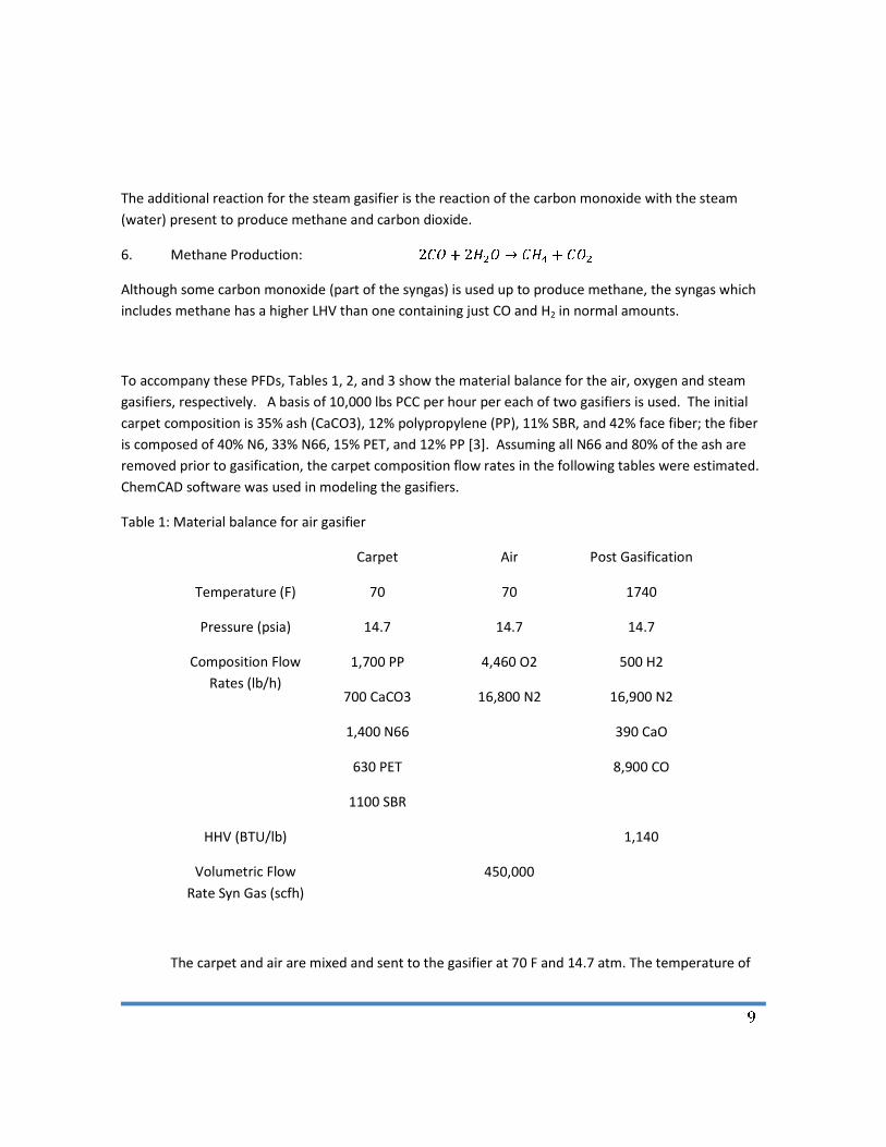
Table 1: Material balance for air gasifier
Carpet Air Post Gasification
Temperature (F) 70 70 1740
Pressure (psia) 14.7 14.7 14.7
Composition Flow
Rates (lb/h)
1,700 PP
700 CaCO3
1,400 N66
630 PET
1100 SBR
4,460 O2
16,800 N2
500 H2
16,900 N2
390 CaO
8,900 CO
HHV (BTU/lb) 1,140
Volumetric Flow
Rate Syn Gas (scfh)
450,000
The carpet and air are mixed and sent to the gasifier at 70 F and 14.7 atm. The temperature of
10
the stream leaving the gasifier is 1740 F. The flow rate of the syn gas including N2 is 450,000 standard
cubic feet per hour.
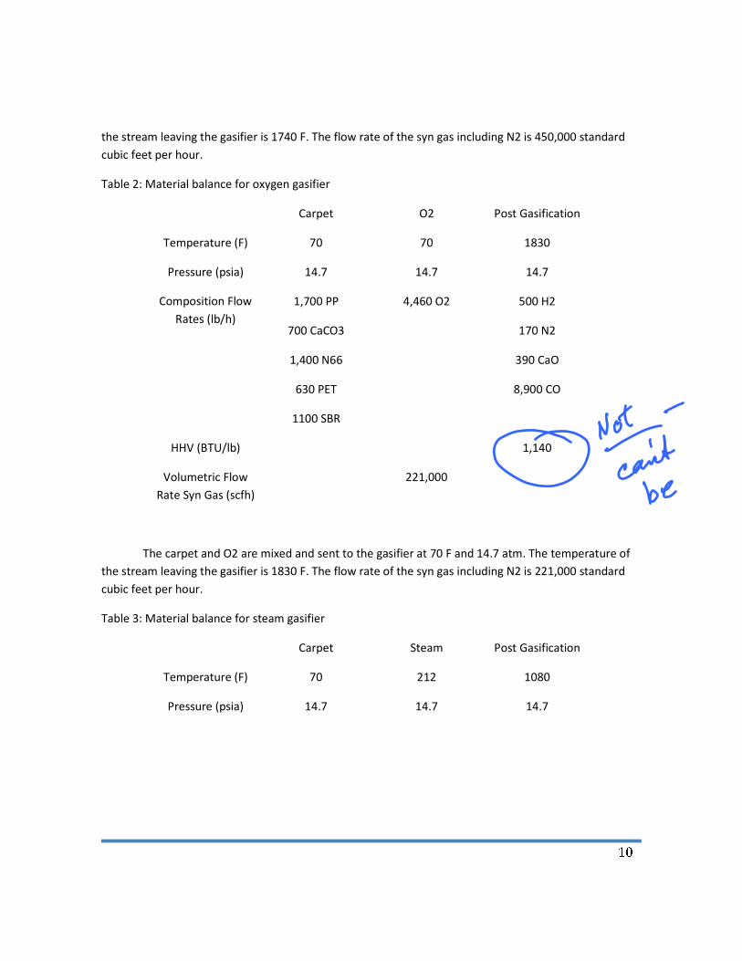
Table 2: Material balance for oxygen gasifier
Carpet O2 Post Gasification
Temperature (F) 70 70 1830
Pressure (psia) 14.7 14.7 14.7
Composition Flow
Rates (lb/h)
1,700 PP
700 CaCO3
1,400 N66
630 PET
1100 SBR
4,460 O2
500 H2
170 N2
390 CaO
8,900 CO
HHV (BTU/lb) 1,140
Volumetric Flow
Rate Syn Gas (scfh)
221,000
The carpet and O2 are mixed and sent to the gasifier at 70 F and 14.7 atm. The temperature of
the stream leaving the gasifier is 1830 F. The flow rate of the syn gas including N2 is 221,000 standard
cubic feet per hour.
Table 3: Material balance for steam gasifier
Carpet Steam Post Gasification
Temperature (F) 70 212 1080
Pressure (psia) 14.7 14.7 14.7
11
Composition Flow
Rates (lb/h)
1,700 PP
700 CaCO3
1,400 N66
630 PET
1100 SBR
3,850 H2O
630 H2
110 O2
170 N2
390 CaO
6,900 CO
1,200 CH4
HHV (BTU/lb) 3,470
Volumetric Flow
Rate Syn Gas (scfh)
250,000
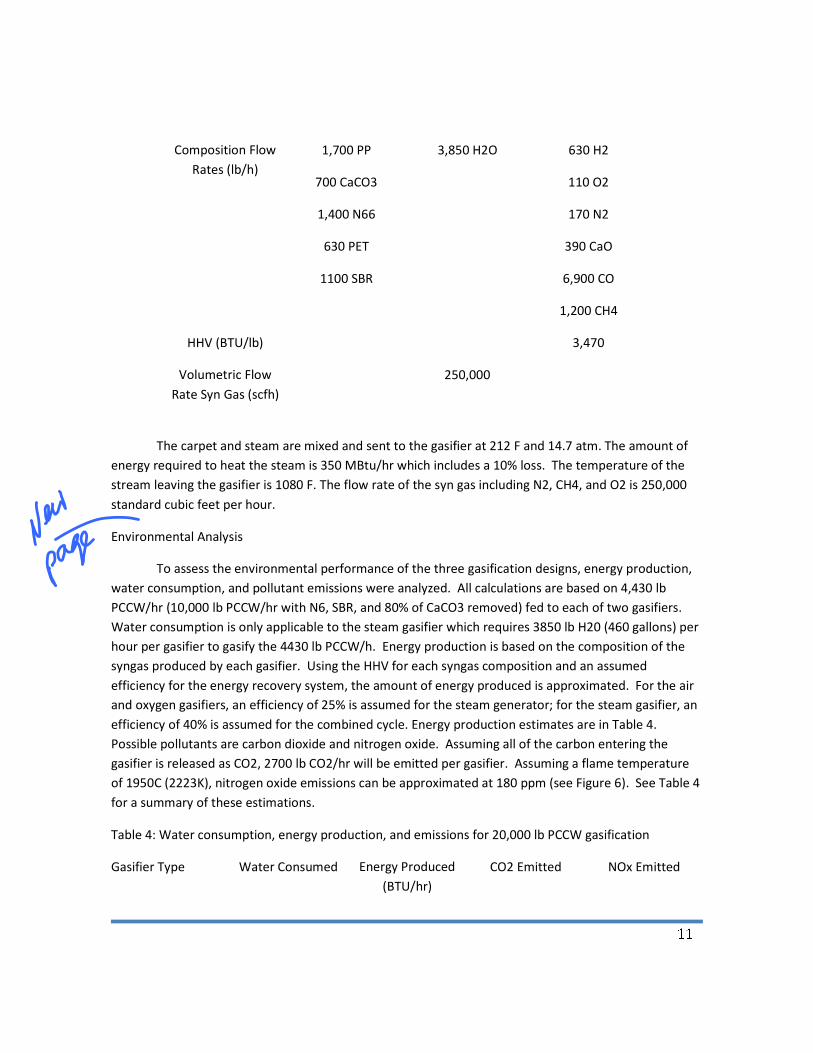
The carpet and steam are mixed and sent to the gasifier at 212 F and 14.7 atm. The amount of
energy required to heat the steam is 350 MBtu/hr which includes a 10% loss. The temperature of the
stream leaving the gasifier is 1080 F. The flow rate of the syn gas including N2, CH4, and O2 is 250,000
standard cubic feet per hour.
Environmental Analysis
To assess the environmental performance of the three gasification designs, energy production,
water consumption, and pollutant emissions were analyzed. All calculations are based on 4,430 lb
PCCW/hr (10,000 lb PCCW/hr with N6, SBR, and 80% of CaCO3 removed) fed to each of two gasifiers.
Water consumption is only applicable to the steam gasifier which requires 3850 lb H20 (460 gallons) per
hour per gasifier to gasify the 4430 lb PCCW/h. Energy production is based on the composition of the
syngas produced by each gasifier. Using the HHV for each syngas composition and an assumed
efficiency for the energy recovery system, the amount of energy produced is approximated. For the air
and oxygen gasifiers, an efficiency of 25% is assumed for the steam generator; for the steam gasifier, an
efficiency of 40% is assumed for the combined cycle. Energy production estimates are in Table 4.
Possible pollutants are carbon dioxide and nitrogen oxide. Assuming all of the carbon entering the
gasifier is released as CO2, 2700 lb CO2/hr will be emitted per gasifier. Assuming a flame temperature
of 1950C (2223K), nitrogen oxide emissions can be approximated at 180 ppm (see Figure 6). See Table 4
for a summary of these estimations.
Table 4: Water consumption, energy production, and emissions for 20,000 lb PCCW gasification
Gasifier Type Water Consumed Energy Produced
(BTU/hr)
CO2 Emitted NOx Emitted
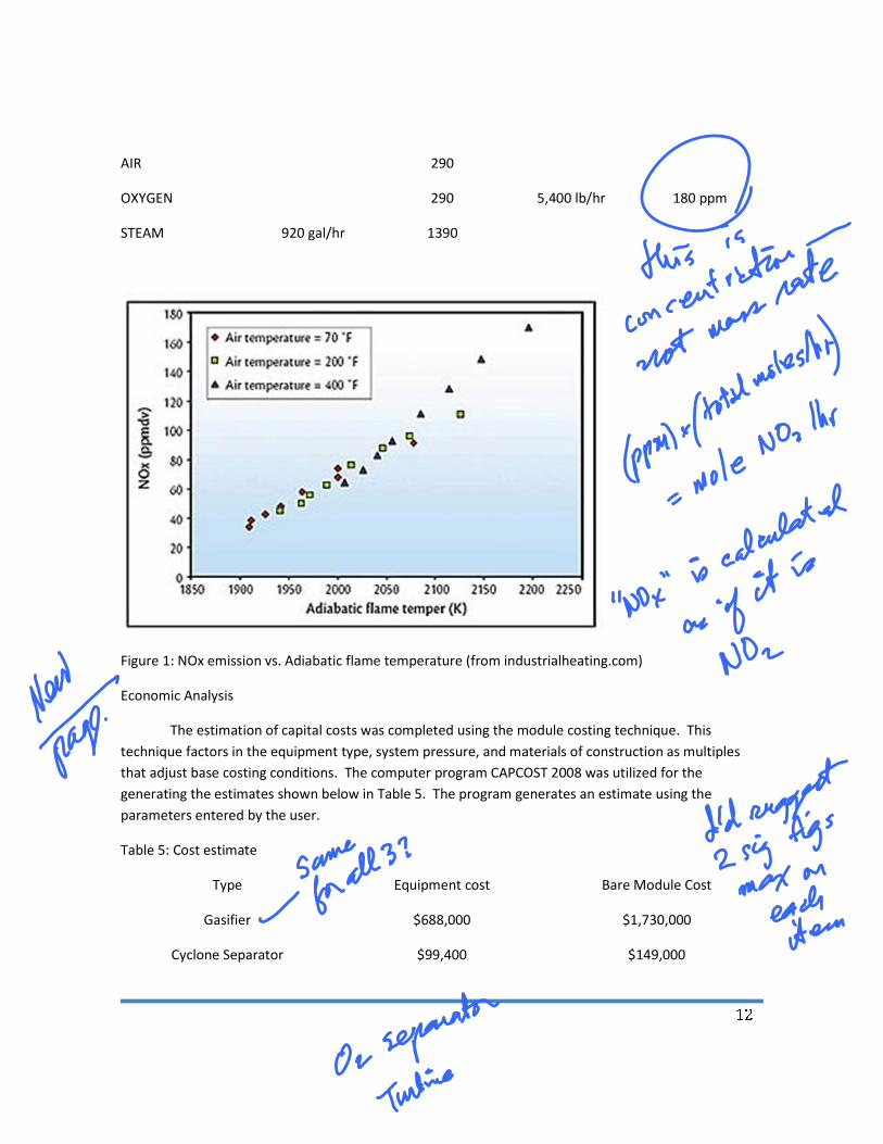
12
AIR 290
5,400 lb/hr
180 ppm OXYGEN 290
STEAM 920 gal/hr 1390
Figure 1: NOx emission vs. Adiabatic flame temperature (from industrialheating.com)
Economic Analysis
The estimation of capital costs was completed using the module costing technique. This
technique factors in the equipment type, system pressure, and materials of construction as multiples
that adjust base costing conditions. The computer program CAPCOST 2008 was utilized for the
generating the estimates shown below in Table 5. The program generates an estimate using the
parameters entered by the user.
Table 5: Cost estimate
Type Equipment cost Bare Module Cost
Gasifier $688,000 $1,730,000
Cyclone Separator $99,400 $149,000
13
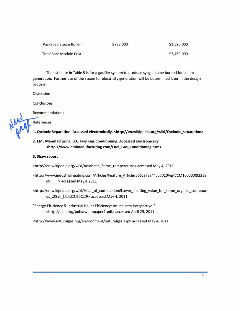
Packaged Steam Boiler $733,000 $1,590,000
Total Bare Module Cost $3,469,000
The estimate in Table 5 is for a gasifier system to produce syngas to be burned for steam
generation. Further use of the steam for electricity generation will be determined later in the design
process.
Discussion
Conclusions
Recommendations
References
1. Cyclonic Separation. Accessed electronically. <http://en.wikipedia.org/wiki/Cyclonic_separation>.
2. EML Manufacturing, LLC. Fuel Gas Conditioning. Accessed electronically.
<http://www.emlmanufacturing.com/Fuel_Gas_Conditioning.htm>.
3. Shaw report
<http://en.wikipedia.org/wiki/Adiabatic_flame_temperature> accessed May 4, 2011
<http://www.industrialheating.com/Articles/Feature_Article/566ce7aa44cb7010VgnVCM100000f932a8
c0____> accessed May 4,2011
<http://en.wikipedia.org/wiki/Heat_of_combustion#Lower_heating_value_for_some_organic_compoun
ds_.28at_15.4.C2.B0C.29> accessed May 4, 2011
“Energy Efficiency & Industrial Boiler Efficiency: An Industry Perspective.”
<http://cibo.org/pubs/whitepaper1.pdf> accessed April 25, 2011
<http://www.naturalgas.org/environment/naturalgas.asp> accessed May 4, 2011