Embed Size (px)
Citation preview

SREE CHAITANYA COLLEGE OF ENGINEERING: KARIMNAGAR
DEPARTMENT OF MECHANICAL ENGINEERING Engineering workshop manual
INDEX
S.No. Expt.
No.
Name of the Experiment Pg.No.
1 1 TRADE: 1 Carpentry
1.T-Lap joint
2. Dovetail joint
1-13
2 2 TRADE: 2 Fitting 1.v-fitting
2. Dovetail Fitting
14-27
3 3 TRADE: 3 Tin-Smithy and Development of jobs
carried out and soldering.
1.Square Tin
2.cone
28-37
4 4 TRADE: 4 Black Smithy 1.chisel
2.S-Hook
38-47
5 5 TRADE: 5 House-wiring
1.Two lamps control by single switch
2. Two lamps control using Two- way switches
48-57
6 6 TRADE: 6 Foundry
1.A Solid flange single piece pattern
2. Stepped Grove Pulley (split pattern)
58-69
7 7 TRADE: 7 Welding
1.Arc welding –Lap joint
2. Arc welding - Butt joint
70-76
8 8 TRADE: 8 Power tools in construction, wood
working, electrical engineering and mechanical
Engineering.
77-86
TRADES FOR DEMONSTRATION &
EXPOSURE:
9 9 Plumbing 87-90
10 10 Machine Shop 91-94
11 11 Metal Cutting (Water Plasma)
95-98

SREE CHAITANYA COLLEGE OF ENGINEERING: KARIMNAGAR
DEPARTMENT OF MECHANICAL ENGINEERING Engineering workshop manual
CARPENTRY
THEORY
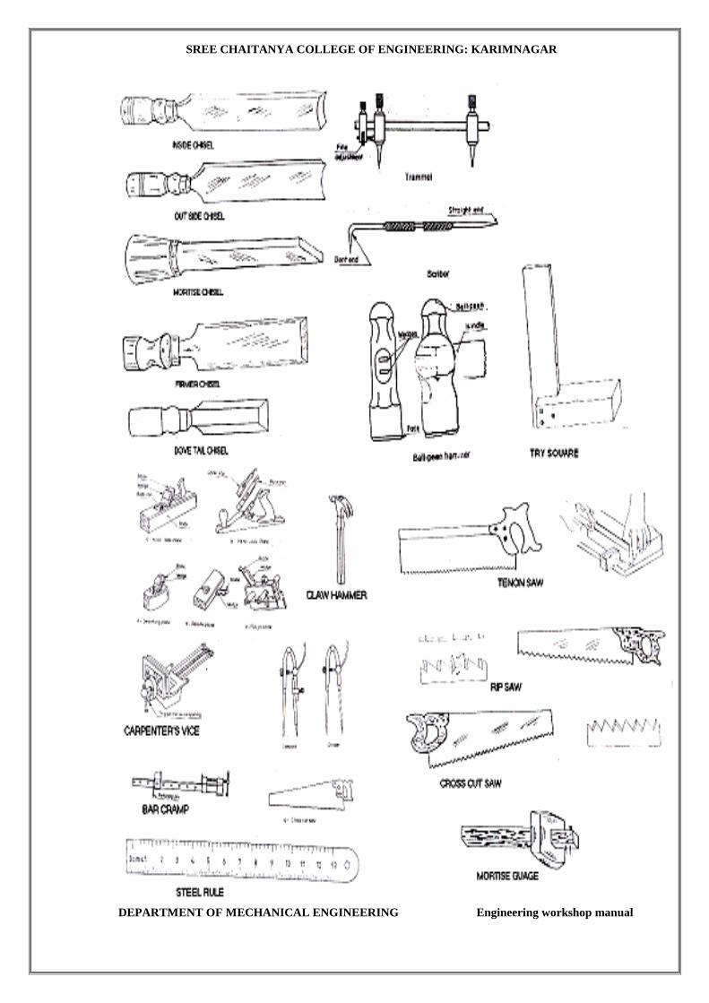
Marking and Measuring Tools:
Accurate marking and measurement is very essential in carpentry work, to produce parts
to exact size. To transfer dimensions onto the work, the following are the marking and
measuring tools that are required in a carpentry shop:
Steel rule:
It is an important tool for linear measurement. It can also be used as a marking tool
Steel tape:
It is used for large measurements, such as marking on board and checking the overall
dimensions of the work
Marking gauge:
It is a tool used to mark lines parallel to the edge of a wooden piece. It consists of a
square wooden stem with a sliding wooden stock (head) on it. On the stem is fitted a
marking pin, made of steel. The stock is set at any desired distance from the marking
point and fixed in position by a screw. It must be ensured that the marking pin projects
through the stem, about 2 mm and the end is sharp enough to make a very fine line. A
mortise gauge consists of two pins. In this, it is possible to adjust the distance between
the pins, to draw two parallel lines on the stock.
Try-Square:
It is used for marking and testing the square ness and straightness of planed surfaces. It
consists of a steel blade, fitted in a cast iron stock. It is also used for checking the
planed surfaces for flatness. Its size varies from 150 to 300mm, according to the length
of the blade. It is less accurate when compared to the try-square used in the fitting shop.
Compass and divider: They are used for marking Arcs and circles on the planed surfaces of the wood.
Scriber or marking knife:
It is used for marking on timber. It is made of steel, having one end pointed and the
other end formed into a sharp cutting edge.
Bevel: It is used for laying-out and checking angles. The blade of the bevel is adjustable and
may be held in place by a thumb screw. After it is set to the desired angle, it can be
used in much the same way as a try-square. A good way to set it to the required angle is
to mark the angle on a surface and then adjust the blade to fit the angle.
SREE CHAITANYA COLLEGE OF ENGINEERING: KARIMNAGAR
DEPARTMENT OF MECHANICAL ENGINEERING Engineering workshop manual
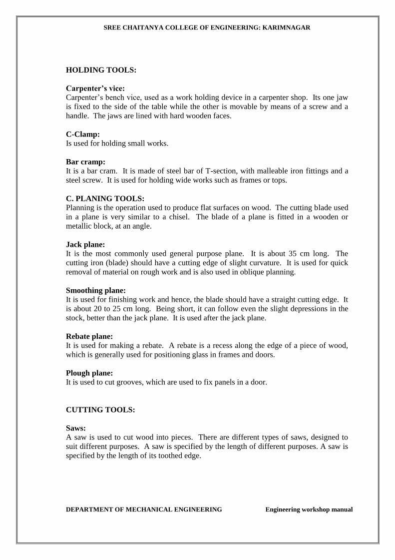
HOLDING TOOLS:
Carpenter’s vice:
Carpenter’s bench vice, used as a work holding device in a carpenter shop. Its one jaw
is fixed to the side of the table while the other is movable by means of a screw and a
handle. The jaws are lined with hard wooden faces.
C-Clamp:
Is used for holding small works.
Bar cramp:
It is a bar cram. It is made of steel bar of T-section, with malleable iron fittings and a
steel screw. It is used for holding wide works such as frames or tops.
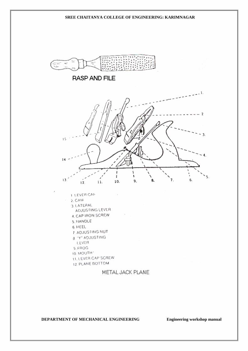
C. PLANING TOOLS:
Planning is the operation used to produce flat surfaces on wood. The cutting blade used
in a plane is very similar to a chisel. The blade of a plane is fitted in a wooden or
metallic block, at an angle.
Jack plane:
It is the most commonly used general purpose plane. It is about 35 cm long. The
cutting iron (blade) should have a cutting edge of slight curvature. It is used for quick
removal of material on rough work and is also used in oblique planning.
Smoothing plane:
It is used for finishing work and hence, the blade should have a straight cutting edge. It
is about 20 to 25 cm long. Being short, it can follow even the slight depressions in the
stock, better than the jack plane. It is used after the jack plane.
Rebate plane: It is used for making a rebate. A rebate is a recess along the edge of a piece of wood,
which is generally used for positioning glass in frames and doors.
Plough plane:
It is used to cut grooves, which are used to fix panels in a door.
CUTTING TOOLS:
Saws:
A saw is used to cut wood into pieces. There are different types of saws, designed to
suit different purposes. A saw is specified by the length of different purposes. A saw is
specified by the length of its toothed edge.
SREE CHAITANYA COLLEGE OF ENGINEERING: KARIMNAGAR
DEPARTMENT OF MECHANICAL ENGINEERING Engineering workshop manual
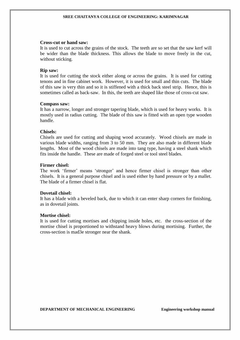
Cross-cut or hand saw:
It is used to cut across the grains of the stock. The teeth are so set that the saw kerf will
be wider than the blade thickness. This allows the blade to move freely in the cut,
without sticking.
Rip saw:
It is used for cutting the stock either along or across the grains. It is used for cutting
tenons and in fine cabinet work. However, it is used for small and thin cuts. The blade
of this saw is very thin and so it is stiffened with a thick back steel strip. Hence, this is
sometimes called as back-saw. In this, the teeth are shaped like those of cross-cut saw.
Compass saw:
It has a narrow, longer and stronger tapering blade, which is used for heavy works. It is
mostly used in radius cutting. The blade of this saw is fitted with an open type wooden
handle.
Chisels: Chisels are used for cutting and shaping wood accurately. Wood chisels are made in
various blade widths, ranging from 3 to 50 mm. They are also made in different blade
lengths. Most of the wood chisels are made into tang type, having a steel shank which
fits inside the handle. These are made of forged steel or tool steel blades.
Firmer chisel: The work ‘firmer’ means ‘stronger’ and hence firmer chisel is stronger than other
chisels. It is a general purpose chisel and is used either by hand pressure or by a mallet.
The blade of a firmer chisel is flat.
Dovetail chisel:
It has a blade with a beveled back, due to which it can enter sharp corners for finishing,
as in dovetail joints.
Mortise chisel:
It is used for cutting mortises and chipping inside holes, etc. the cross-section of the
mortise chisel is proportioned to withstand heavy blows during mortising. Further, the
cross-section is mad3e stronger near the shank.
SREE CHAITANYA COLLEGE OF ENGINEERING: KARIMNAGAR
DEPARTMENT OF MECHANICAL ENGINEERING Engineering workshop manual
SREE CHAITANYA COLLEGE OF ENGINEERING: KARIMNAGAR
DEPARTMENT OF MECHANICAL ENGINEERING Engineering workshop manual

SREE CHAITANYA COLLEGE OF ENGINEERING: KARIMNAGAR
DEPARTMENT OF MECHANICAL ENGINEERING Engineering workshop manual
REVIEW QUESTIONS:
1 Name the commonly available shapes of timber in the market.
2. Classify wood used for construction purpose.
3. What is the difference between marking gauge and marking knife?
4. What is the difference between C-clamp and bar cramp?
5. What for a plane is used in a carpentry shop?
6. Classify the planning tools.
7. Classify the chisels and their applications.
8. Name the tools used for pulling nails.
9. On what parameters, the strength of the joint depends?
10. Name the various joinery materials used in carpentry.
11. Name the various types of joints under,
i. lap joints,
ii. mortise and tenon joints, and
iii. bridle joints.

SREE CHAITANYA COLLEGE OF ENGINEERING: KARIMNAGAR
DEPARTMENT OF MECHANICAL ENGINEERING Engineering workshop manual
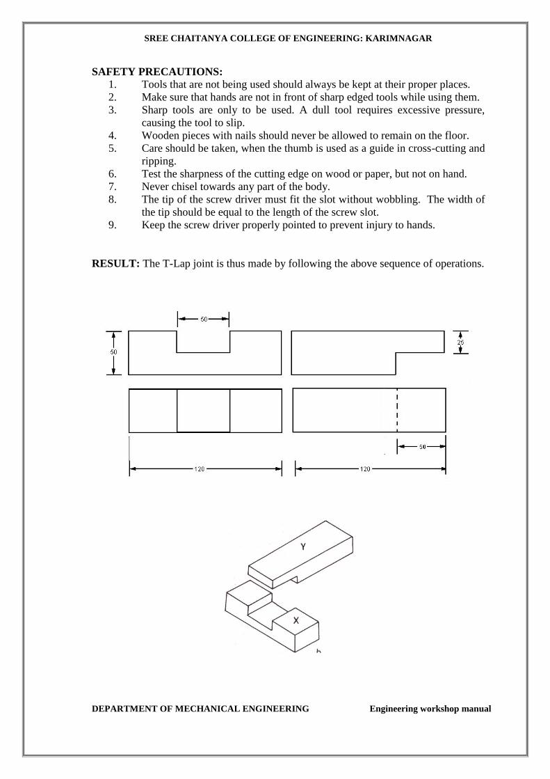
T - LAP JOINT
Expt. No.:1
AIM: To make a T-lap joint as shown in Figure from the given reaper of size 50 x 50x
250 mm.
TOOLS REQUIRED : Carpenter's vice, steel rule, jack plane, try-square, marking
gauge, 25 mm firmer chisel, cross-cut saw, tenon saw, scriber and mallet.
MATERIAL REQUIRED: 50X50X250mm wood - two pieces.
SEQUENCE OF OPTIONS
1. CUTTING
2. PLANING
3. INSPECTION
PROCEDURE
1. The given reaper is checked to ensure its correct size.
2. The reaper is firmly clamped in the carpenter's vice and any two adjacent faces
are planed by the jack plane and the two faces are checked for square ness with
the try-square.
3. Marking gauge is set and lines are drawn at 50 and 50 mm, to mark the thickness
and width of the model respectively.
4. The excess material is first chiseled out with firmer chisel and then planed to
correct size.
5. The mating dimensions of the parts X and Yare then marked using scale and
marking gauge.
6. Using the cross-cut saw, the portions to be removed are cut in both the pieces,
followed by chiseling and also the parts X and Yare separated by cross-cutting,
using the tenon saw.
7. The ends of both the parts are chiseled to the exact lengths.
8. A fine finishing is given to the parts, if required so that, proper fitting is
obtained.
9. The parts are fitted to obtain a slightly tight joint.
SREE CHAITANYA COLLEGE OF ENGINEERING: KARIMNAGAR
DEPARTMENT OF MECHANICAL ENGINEERING Engineering workshop manual
SAFETY PRECAUTIONS:
1. Tools that are not being used should always be kept at their proper places.
2. Make sure that hands are not in front of sharp edged tools while using them.
3. Sharp tools are only to be used. A dull tool requires excessive pressure,
causing the tool to slip.
4. Wooden pieces with nails should never be allowed to remain on the floor.
5. Care should be taken, when the thumb is used as a guide in cross-cutting and
ripping.
6. Test the sharpness of the cutting edge on wood or paper, but not on hand.
7. Never chisel towards any part of the body.
8. The tip of the screw driver must fit the slot without wobbling. The width of
the tip should be equal to the length of the screw slot.
9. Keep the screw driver properly pointed to prevent injury to hands.
RESULT: The T-Lap joint is thus made by following the above sequence of operations.
SREE CHAITANYA COLLEGE OF ENGINEERING: KARIMNAGAR
DEPARTMENT OF MECHANICAL ENGINEERING Engineering workshop manual
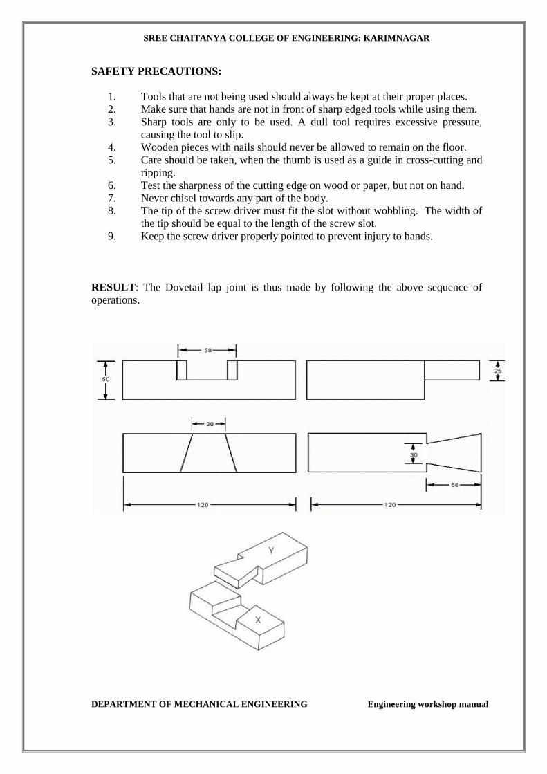
DOVE TAIL LAP JOINT
Expt No: 2
AIM: To make a Dovetail lap joint
APPARATUS & TOOLS REQUIRED:
Carpenter's vice, steel rule, jack plane, try-square, marking gauge, 25 mm firmer chisel,
cross-cut saw, tenon saw, scriber and mallet.
MATERIAL REQUIRED: 50X50X250mm wood - two pieces.
SEQUENCE OF OPTIONS
1. CUTTING
2. PLANING
3. INSPECTION
PROCEDURE:
1. The given reaper is checked to ensure its correct size.
2. The reaper is firmly clamped in the carpenter's vice and any two adjacent
faces are planed by the jack plane and the two faces are checked for square
ness with the try square.
3. Marking gauge is set and lines are drawn at 50 and 50 mm, to mark the
thickness and width of the model respectively. .
4. The excess material is first chiseled out with firmer chisel and then planed to
correct Size.
5. The mating dimensions of the parts X and Yare then marked using scale and
marking gauge.
6. Using the cross-cut saw, the portions to be removed are cut in both the
pieces, followed by chiseling and also the parts X and Yare separated by
cross cutting, using the tenon saw
7. The ends of both the parts are chiseled to exact lengths.
8. A fine finishing is given to the parts, if required so that, proper fitting is
obtained.
9. The parts are fitted to obtain a slightly tight joint.
SREE CHAITANYA COLLEGE OF ENGINEERING: KARIMNAGAR
DEPARTMENT OF MECHANICAL ENGINEERING Engineering workshop manual
SAFETY PRECAUTIONS:
1. Tools that are not being used should always be kept at their proper places.
2. Make sure that hands are not in front of sharp edged tools while using them.
3. Sharp tools are only to be used. A dull tool requires excessive pressure,
causing the tool to slip.
4. Wooden pieces with nails should never be allowed to remain on the floor.
5. Care should be taken, when the thumb is used as a guide in cross-cutting and
ripping.
6. Test the sharpness of the cutting edge on wood or paper, but not on hand.
7. Never chisel towards any part of the body.
8. The tip of the screw driver must fit the slot without wobbling. The width of
the tip should be equal to the length of the screw slot.
9. Keep the screw driver properly pointed to prevent injury to hands.
RESULT: The Dovetail lap joint is thus made by following the above sequence of
operations.
SREE CHAITANYA COLLEGE OF ENGINEERING: KARIMNAGAR
DEPARTMENT OF MECHANICAL ENGINEERING Engineering workshop manual
FITTING
THEORY
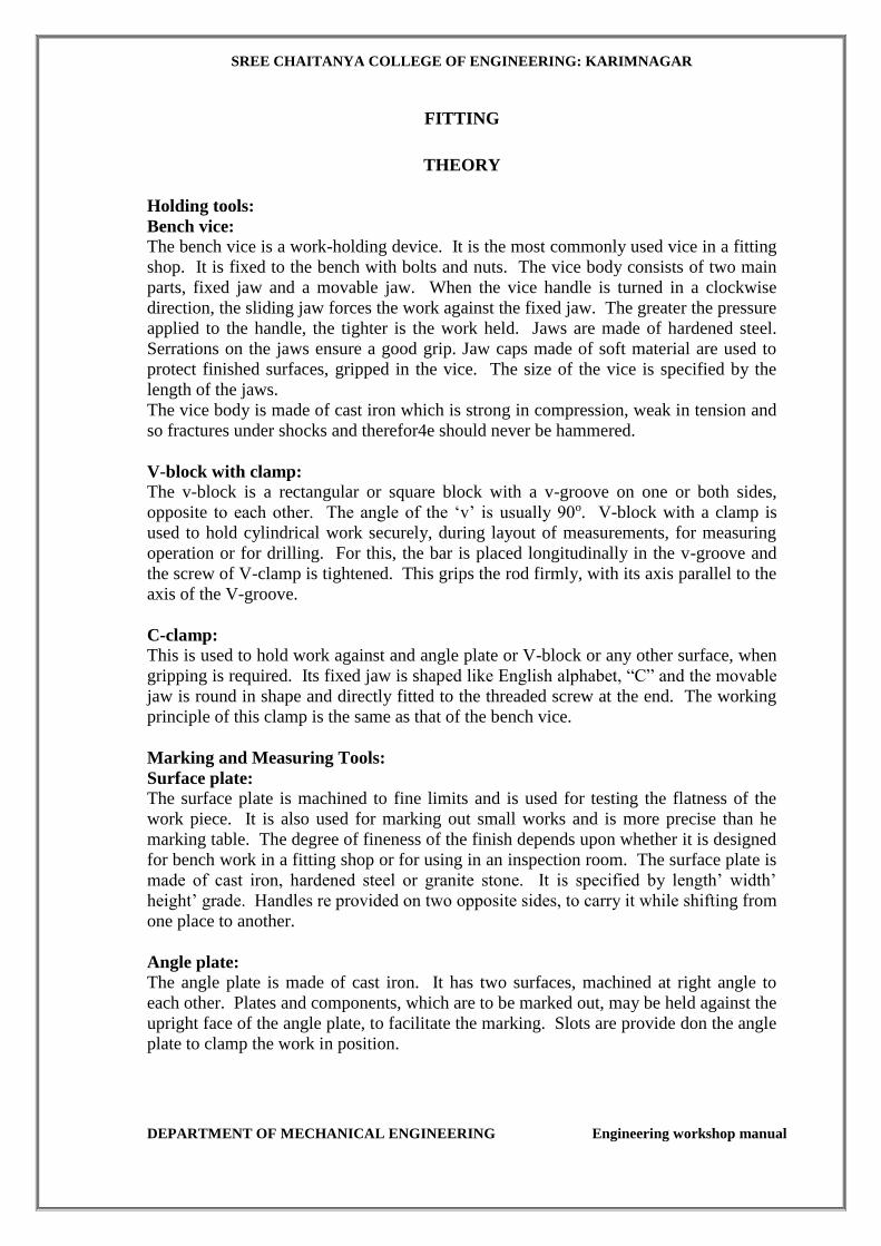
Holding tools:
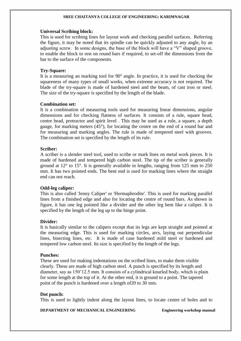
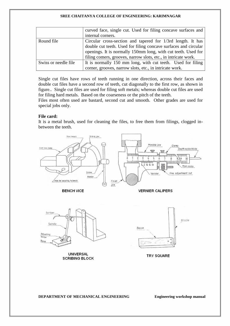
Bench vice: The bench vice is a work-holding device. It is the most commonly used vice in a fitting
shop. It is fixed to the bench with bolts and nuts. The vice body consists of two main
parts, fixed jaw and a movable jaw. When the vice handle is turned in a clockwise
direction, the sliding jaw forces the work against the fixed jaw. The greater the pressure
applied to the handle, the tighter is the work held. Jaws are made of hardened steel.
Serrations on the jaws ensure a good grip. Jaw caps made of soft material are used to
protect finished surfaces, gripped in the vice. The size of the vice is specified by the
length of the jaws.
The vice body is made of cast iron which is strong in compression, weak in tension and
so fractures under shocks and therefor4e should never be hammered.
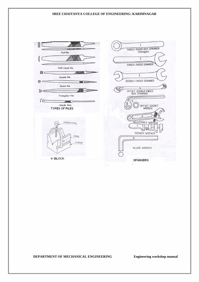
V-block with clamp:
The v-block is a rectangular or square block with a v-groove on one or both sides,
opposite to each other. The angle of the ‘v’ is usually 90o. V-block with a clamp is
used to hold cylindrical work securely, during layout of measurements, for measuring
operation or for drilling. For this, the bar is placed longitudinally in the v-groove and
the screw of V-clamp is tightened. This grips the rod firmly, with its axis parallel to the
axis of the V-groove.
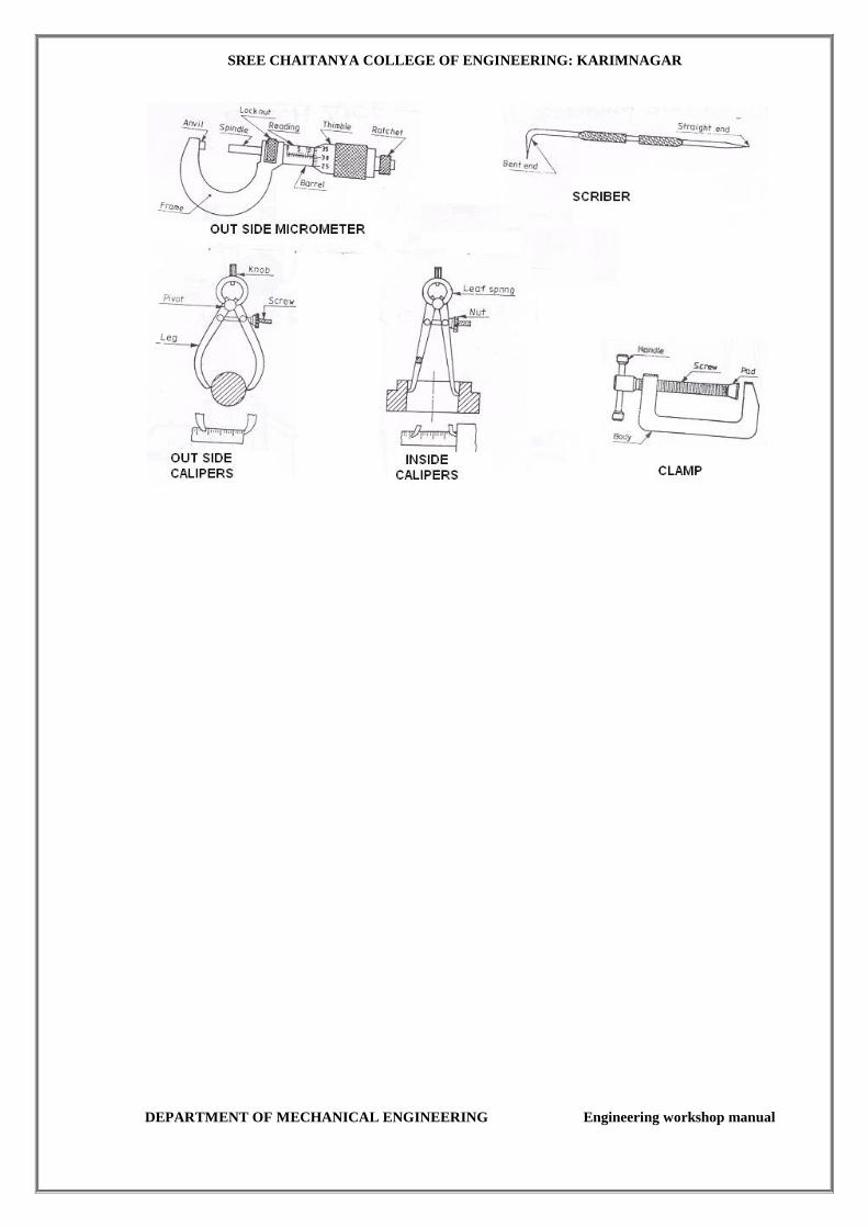
C-clamp:
This is used to hold work against and angle plate or V-block or any other surface, when
gripping is required. Its fixed jaw is shaped like English alphabet, “C” and the movable
jaw is round in shape and directly fitted to the threaded screw at the end. The working
principle of this clamp is the same as that of the bench vice.
Marking and Measuring Tools:
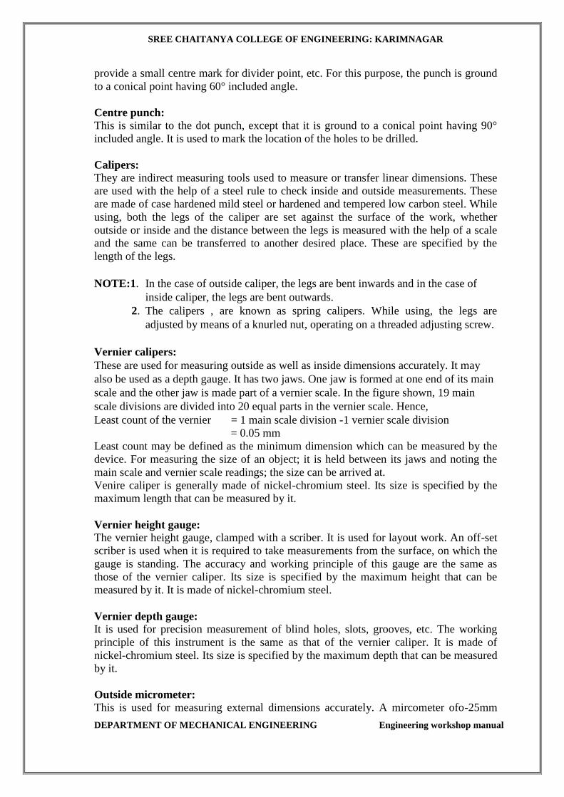
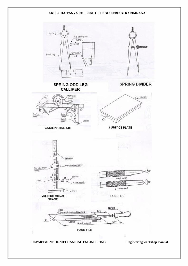
Surface plate:
The surface plate is machined to fine limits and is used for testing the flatness of the
work piece. It is also used for marking out small works and is more precise than he
marking table. The degree of fineness of the finish depends upon whether it is designed
for bench work in a fitting shop or for using in an inspection room. The surface plate is
made of cast iron, hardened steel or granite stone. It is specified by length’ width’
height’ grade. Handles re provided on two opposite sides, to carry it while shifting from
one place to another.
Angle plate:
The angle plate is made of cast iron. It has two surfaces, machined at right angle to
each other. Plates and components, which are to be marked out, may be held against the
upright face of the angle plate, to facilitate the marking. Slots are provide don the angle
plate to clamp the work in position.
SREE CHAITANYA COLLEGE OF ENGINEERING: KARIMNAGAR
DEPARTMENT OF MECHANICAL ENGINEERING Engineering workshop manual
Universal Scribing block:
This is used for scribing lines for layout work and checking parallel surfaces. Referring
the figure, it may be noted that its spindle can be quickly adjusted to any angle, by an
adjusting screw. In some designs, the base of the block will have a “V” shaped groove,
to enable the block to rest on round bars if required, to set-off the dimensions from the
bar to the surface of the components.
Try-Square: It is a measuring an marking tool for 90o angle. In practice, it is used for checking the
squareness of many types of small works, when extreme accuracy is not required. The
blade of the try-square is made of hardened steel and the beam, of cast iron or steel.
The size of the try-square is specified by the length of the blade.
Combination set: It is a combination of measuring tools used for measuring linear dimensions, angular
dimensions and for checking flatness of surfaces. It consists of a rule, square head,
centre head, protractor and spirit level . This may be used as a rule, a square, a depth
gauge, for marking meters (45°), for locating the centre on the end of a round bar and
for measuring and marking angles. The rule is made of tempered steel with grooves.
The combination set is specified by the length of its rule.
Scriber: A scriber is a slender steel tool, used to scribe or mark lines on metal work pieces. It is
made of hardened and tempered high carbon steel. The tip of the scriber is generally
ground at 12° to 15°. It is generally available in lengths, ranging from 125 mm to 250
mm. It has two pointed ends. The bent end is used for marking lines where the straight
end can not reach.
Odd-leg caliper:
This is also called 'Jenny Caliper' or 'Hermaphrodite'. This is used for marking parallel
lines from a finished edge and also for locating the centre of round bars. As shown in
figure, it has one leg pointed like a divider and the other leg bent like a caliper. It is
specified by the length of the leg up to the hinge point.
Divider: It is basically similar to the calipers except that its legs are kept straight and pointed at
the measuring edge. This is used for marking circles, arcs, laying out perpendicular
lines, bisecting lines, etc. It is made of case hardened mild steel or hardened and
tempered low carbon steel. Its size is specified by the length of the legs.
Punches: These are used for making indentations on the scribed lines, to make them visible
clearly. These are made of high carbon steel. A punch is specified by its length and
diameter, say as 150’12.5 mm. It consists of a cylindrical knurled body, which is plain
for some length at the top of it. At the other end, it is ground to a point. The tapered
point of the punch is hardened over a length of20 to 30 mm.
Dot punch: This is used to lightly indent along the layout lines, to locate centre of holes and to
SREE CHAITANYA COLLEGE OF ENGINEERING: KARIMNAGAR
DEPARTMENT OF MECHANICAL ENGINEERING Engineering workshop manual
provide a small centre mark for divider point, etc. For this purpose, the punch is ground
to a conical point having 60° included angle.
Centre punch:
This is similar to the dot punch, except that it is ground to a conical point having 90°
included angle. It is used to mark the location of the holes to be drilled.
Calipers: They are indirect measuring tools used to measure or transfer linear dimensions. These
are used with the help of a steel rule to check inside and outside measurements. These
are made of case hardened mild steel or hardened and tempered low carbon steel. While
using, both the legs of the caliper are set against the surface of the work, whether
outside or inside and the distance between the legs is measured with the help of a scale
and the same can be transferred to another desired place. These are specified by the
length of the legs.
NOTE:1. In the case of outside caliper, the legs are bent inwards and in the case of
inside caliper, the legs are bent outwards.
2. The calipers , are known as spring calipers. While using, the legs are
adjusted by means of a knurled nut, operating on a threaded adjusting screw.
Vernier calipers:
These are used for measuring outside as well as inside dimensions accurately. It may
also be used as a depth gauge. It has two jaws. One jaw is formed at one end of its main
scale and the other jaw is made part of a vernier scale. In the figure shown, 19 main
scale divisions are divided into 20 equal parts in the vernier scale. Hence,
Least count of the vernier = 1 main scale division -1 vernier scale division
= 0.05 mm
Least count may be defined as the minimum dimension which can be measured by the
device. For measuring the size of an object; it is held between its jaws and noting the
main scale and vernier scale readings; the size can be arrived at.
Venire caliper is generally made of nickel-chromium steel. Its size is specified by the
maximum length that can be measured by it.
Vernier height gauge:
The vernier height gauge, clamped with a scriber. It is used for layout work. An off-set
scriber is used when it is required to take measurements from the surface, on which the
gauge is standing. The accuracy and working principle of this gauge are the same as
those of the vernier caliper. Its size is specified by the maximum height that can be
measured by it. It is made of nickel-chromium steel.
Vernier depth gauge: It is used for precision measurement of blind holes, slots, grooves, etc. The working
principle of this instrument is the same as that of the vernier caliper. It is made of
nickel-chromium steel. Its size is specified by the maximum depth that can be measured
by it.
Outside micrometer:
This is used for measuring external dimensions accurately. A mircometer ofo-25mm

SREE CHAITANYA COLLEGE OF ENGINEERING: KARIMNAGAR
DEPARTMENT OF MECHANICAL ENGINEERING Engineering workshop manual
range with an accuracy of 0.01 mm, These are available in different ranges with
interchangeable anvils.
It works on the principle of screw thread's pitch and lead. It consists of one jaw or anvil,
fixed to one end of the frame; another movable jaw, in the form of a round bar, called
the spindle. This spindle is mounted on the other end of the frame and housed in the
thimble.
Inside micrometer:
This is used to measure inside dimension accurately inside micrometer of range
25 to 150mm, with extension rods. The construction of inside micrometer is the same as
outside micrometer except that it has no frame. So, its spindle can be used to take
measurements from inside of blind holes. Except this feature; the principle of working
of inside micrometer is the same as outside micrometer.
Finishing Tools:
Files:
Filing is one of the methods removing small amounts of material from the surface of a
metal part. A file is a hardened steel tool, having slant parallel rows of cutting edges or
teeth on its surfaces. On the faces, the teeth are usually diagonal to the edge. One end of
the file is shaped to fit into a wooden handle. 'The hand file is parallel in width and
tapering slightly in thickness, towards the tip. It is provided with double cut teeth on the
faces, single cut on one edge and no teeth on the other edge, which is known as the safe
edge.
Types of files:
Files are classified according to their shape, cutting teeth and pitch or grade of the teeth.
Table gives types of files and their description and uses.
Type of file Hand file, Description and use:
Type of file Description and use
Hand file Rectangular in section, tapered in thickness but parallel in
width. The faces have double cut teeth and one of the edges,
single cut. The other edge does not have any teeth and hence
called as safe edge file. It is used for filing a surface, at right
angle to an already finished surface.
Flat file Rectangular in section and tapered for 1/3rd length in width
and thickness. The faces have double cut teeth, and the edges,
single cut. Used for general purpose filing.
Square file Square in section and tapered for 1/3rd length on all faces. All
the faces have double cut teeth. Used for filing corners and
slots and also to cut keyways.
Triangle file Equilateral triangular in section and tapered for 1/3rd length on
all faces. All the faces have double cut teeth. Used for filing
internal corners.
Half round file It has one flat face, connected by a curved face and tapered for
1/3rd length. The curved face is not exactly semi-circular but
only a part of circle. The flat face has double cut teeth and the
SREE CHAITANYA COLLEGE OF ENGINEERING: KARIMNAGAR
DEPARTMENT OF MECHANICAL ENGINEERING Engineering workshop manual
curved face, single cut. Used for filing concave surfaces and
internal corners.
Round file Circular cross-section and tapered for 1/3rd length. It has
double cut teeth. Used for filing concave surfaces and circular
openings. It is normally 150mm long, with cut teeth. Used for
filing comers, grooves, narrow slots, etc., in intricate work.
Swiss or needle file It is normally 150 mm long, with cut teeth. Used for filing
corner, grooves, narrow slots, etc., in intricate work.
Single cut files have rows of teeth running in one direction, across their faces and
double cut files have a second row of teeth, cut diagonally to the first row, as shown in
figure.. Single cut files are used for filing soft metals; whereas double cut files are used
for filing hard metals. Based on the coarseness or the pitch of the teeth.
Files most often used are bastard, second cut and smooth. Other grades are used for
special jobs only.
File card:
It is a metal brush, used for cleaning the files, to free them from filings, clogged in-
between the teeth.
SREE CHAITANYA COLLEGE OF ENGINEERING: KARIMNAGAR
DEPARTMENT OF MECHANICAL ENGINEERING Engineering workshop manual
SREE CHAITANYA COLLEGE OF ENGINEERING: KARIMNAGAR
DEPARTMENT OF MECHANICAL ENGINEERING Engineering workshop manual
SREE CHAITANYA COLLEGE OF ENGINEERING: KARIMNAGAR
DEPARTMENT OF MECHANICAL ENGINEERING Engineering workshop manual

SREE CHAITANYA COLLEGE OF ENGINEERING: KARIMNAGAR
DEPARTMENT OF MECHANICAL ENGINEERING Engineering workshop manual
V-FITTING
EXPT.NO: 01
AIM: To make a V-Fit from the given mid steel pieces. MATERIALS REQUIRED:
Mild steel flat (40x40x3mm). TOOLS AND EQUIPMENT REQUIRED:
1.6”try square
2. 6”sriber
3. Odd leg caliper 3.12”hack saw Frame
4 Blades (12 TPI)
5.10”rough file
6.10”smooth file
7.10”triangle file
8. Knife Edge file
9. Dot punch
10. Ball peen hammer (0.5 Ib)
11. Steel Rule
Sequence of Operations:
1. Filling
2. Marking
3. Punching
4. Sawing
5. Filling
6. Finishing
PROCEDURE:
1. The given mild steel flat piece is checked for given dimensions.
2. One edge of given is filled with rough and smooth files and checked with try square
for straightness.
3. An adjacent edge is also filled such that it is square to first edge and checked with try
square.
4. Wet chalk is applied on one side of the flat and dried for marking.
5. Lines are marked according to given figure, using odd leg caliper and steel rule.
6. Using the dot punch, punches are made along the marked lines.
7. The excess materials removed from the remaining two edges with try square level up
to half of the marked dots.
8. Finally buts are removed by the filling on the surface of the fitted job.

SREE CHAITANYA COLLEGE OF ENGINEERING: KARIMNAGAR
DEPARTMENT OF MECHANICAL ENGINEERING Engineering workshop manual
PRECAUTIONS: 1. the perpendicularity of face ends edges is checked perfectly by
using try square.
2. Finishing is given by using only with smooth files.
3. Marking is done without parallax error.
RESULT: The required V-fit is done successfully according to the drawing.
SREE CHAITANYA COLLEGE OF ENGINEERING: KARIMNAGAR
DEPARTMENT OF MECHANICAL ENGINEERING Engineering workshop manual
DOVETAIL FITTING
Expt. No: 2
AIM: To make a dovetail fitting from the given two M.S. pieces.
APPARATUS & TOOLS REQUIRED: Bench vice, steel rule, try-square, ball-peen
hammer, scriber, dot punch, set of files, surface plate, Jenny caliper, hack saw with
blade and flat chisel.
MATERIAL REQUIRED: 50x50x6mm M.S. Flat Two Pieces.
SEQUENCE OF OPERATIONS:
1. CUTTING
2. FILING
3. ASSEMBLING
4. CHECKING / INSPECTION
PROCEDURE:
1. The burrs in the pieces are removed and the dimensions are checked with the
steel rule.
2. The pieces are clamped one after the other and the outer mating edges are filed
and checked for their flatness, with the help of the try-square.
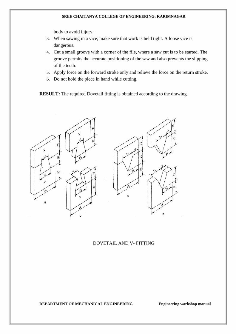
3. The side edges of the two pieces are filed such that, they are at right angle to
each other and widths are exactly 48 mm.
4. Chalk is then applied on the surfaces of the two pieces.
5. The given dimensions of the dovetail fitting are marked, by using the Jenny
caliper, steel rule and surface plate.
6. Using the dot punch, dots are punched along the above scribed lines.
7. Using the hack saw, the unwanted portions are removed.
8. Using the flat chisel, the unwanted material in the piece Y is removed.
9. The cut edges are filed by the half round file.
10. The corners of the stepped surfaces are filed by using a square or triangular file
to get the sharp corners.
The pieces (X and Y) are fitted together and the mating is checked for the correctness of
the fit, any defects noticed, is rectified by filing with a smooth file.
SAFETY PRECAUTIONS:
1. Keep the tools clean, free of dirt, oil and grease.
2. Keep the tools sharp and in good condition. Hold the pointed tool away from the
SREE CHAITANYA COLLEGE OF ENGINEERING: KARIMNAGAR
DEPARTMENT OF MECHANICAL ENGINEERING Engineering workshop manual
body to avoid injury.
3. When sawing in a vice, make sure that work is held tight. A loose vice is
dangerous.
4. Cut a small groove with a corner of the file, where a saw cut is to be started. The
groove permits the accurate positioning of the saw and also prevents the slipping
of the teeth.
5. Apply force on the forward stroke only and relieve the force on the return stroke.
6. Do not hold the piece in hand while cutting.
RESULT: The required Dovetail fitting is obtained according to the drawing.
DOVETAIL AND V- FITTING
SREE CHAITANYA COLLEGE OF ENGINEERING: KARIMNAGAR
DEPARTMENT OF MECHANICAL ENGINEERING engineering workshop manual 32
TIN SMITHY
THEORY
SHEET METAL MATERIALS:
A variety of metals are used in a sheet metal shop such as black iron, galvanized iron, copper,
tin, aluminum and stainless steel.
BLACK IRON
Black iron is the cheapest metal. The name black iron is because of its black color. It is rolled
to the desired thickness and then annealed. It corrodes rapidly, because it is not coated. The
application of this metal is limited to articles that are to be painted.
GI
A sheet of soft steel, which is coated with molten zinc is known as galvanized iron. The zinc
coat forms a coating that resists rust, improves the appearance of the metal and permits it to be
soldered with greater ease.
COPPER
Copper sheets are available as cold or hot rolled sheets. Copper is highly resistant to corrosion.
As it is a ductile material, copper sheets can be formed into complex shapes and the joints can
be brazed easily.
TIN
Iron sheets, coated with tin are known as tin sheets. Tin sheets are used for dairy equipment,
cans, pans, food containers, etc. The thickness of tin sheets are denoted by special marks and
not by gauge numbers.
ALUMINIUM
Aluminium in the form of sheets can be used with the addition of small quantities of metals
like copper, silicon, manganese and iron. It is widely used for processing vessels and tanks,
house-hold appliances, refrigerator trays, kettles, etc. Aircraft structures are mainly made
from aluminium and its alloys.
STAINLES STEEL
Stainless steel is an alloy of steel with 8-10% nickel, 18% chromium and traces of other
metals. It has got greater resistance to corrosion and can be welded. It is used for making
kitchen-ware, dairy and food processing plants, chemical plants, etc.
SREE CHAITANYA COLLEGE OF ENGINEERING: KARIMNAGAR
DEPARTMENT OF MECHANICAL ENGINEERING engineering workshop manual 33
HAND TOOLS:
The common hand tools used in sheet metal work are, steel rule, usually of 60 cm length, wire
gauge, dot punch, trammel, scriber, ball-peen hammer, straight-peen-hammer, cross-peen
hammer, mallet, snips and soldering iron.
Trammel:
Sheet metal layout requires marking of arcs and circles. This may be done by using the
trammel, as shown in Fig. 10.1. The length of the beam decides the maximum size of the arc
that can be scribed.
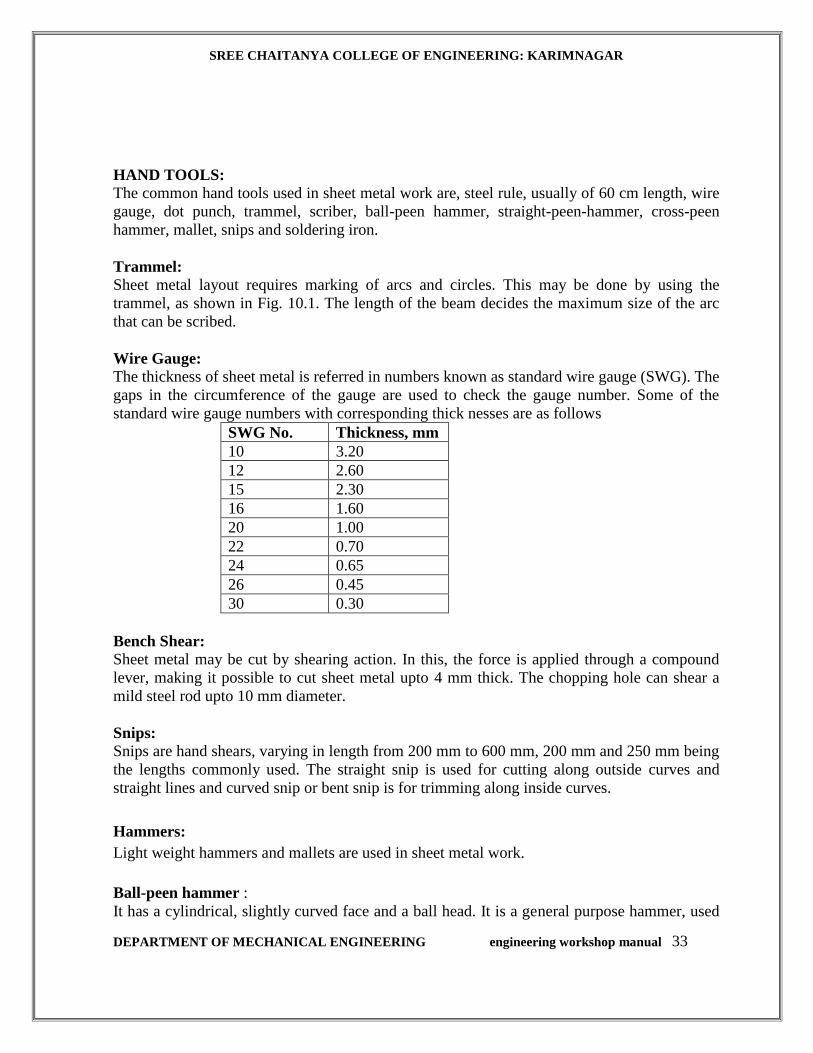
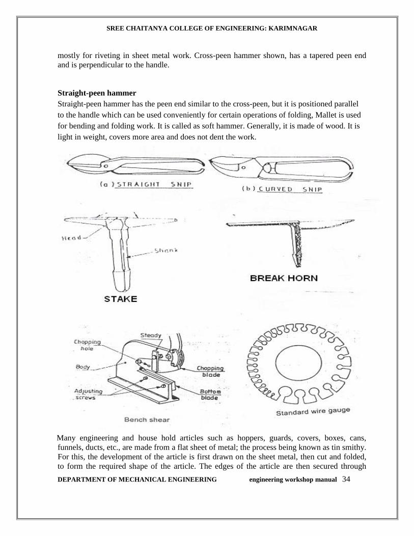
Wire Gauge:
The thickness of sheet metal is referred in numbers known as standard wire gauge (SWG). The
gaps in the circumference of the gauge are used to check the gauge number. Some of the
standard wire gauge numbers with corresponding thick nesses are as follows
SWG No. Thickness, mm
10 3.20
12 2.60
15 2.30
16 1.60
20 1.00
22 0.70
24 0.65
26 0.45
30 0.30
Bench Shear:
Sheet metal may be cut by shearing action. In this, the force is applied through a compound
lever, making it possible to cut sheet metal upto 4 mm thick. The chopping hole can shear a
mild steel rod upto 10 mm diameter.
Snips:
Snips are hand shears, varying in length from 200 mm to 600 mm, 200 mm and 250 mm being
the lengths commonly used. The straight snip is used for cutting along outside curves and
straight lines and curved snip or bent snip is for trimming along inside curves.
Hammers:
Light weight hammers and mallets are used in sheet metal work.
Ball-peen hammer :
It has a cylindrical, slightly curved face and a ball head. It is a general purpose hammer, used
SREE CHAITANYA COLLEGE OF ENGINEERING: KARIMNAGAR
DEPARTMENT OF MECHANICAL ENGINEERING engineering workshop manual 34
mostly for riveting in sheet metal work. Cross-peen hammer shown, has a tapered peen end
and is perpendicular to the handle.
Straight-peen hammer
Straight-peen hammer has the peen end similar to the cross-peen, but it is positioned parallel
to the handle which can be used conveniently for certain operations of folding, Mallet is used
for bending and folding work. It is called as soft hammer. Generally, it is made of wood. It is
light in weight, covers more area and does not dent the work.
Many engineering and house hold articles such as hoppers, guards, covers, boxes, cans,
funnels, ducts, etc., are made from a flat sheet of metal; the process being known as tin smithy.
For this, the development of the article is first drawn on the sheet metal, then cut and folded,
to form the required shape of the article. The edges of the article are then secured through

SREE CHAITANYA COLLEGE OF ENGINEERING: KARIMNAGAR
DEPARTMENT OF MECHANICAL ENGINEERING engineering workshop manual 35
welding, brazing, soldering, riveting, etc. For successful working in the trade, one should have
a thorough knowledge of projective geometry and development of surfaces. .
Allowance should be given in the drawing stage for folding and bending. This allowance
depends upon the radius of the bend and thickness of the sheet metal.
REVIEW QUESTIONS:
1 Describe the process of sheet metal work.
2 What are the articles that are normally made of sheet metal?
3 What-are the points to be considered, during the sheet metal work?
4 Name the various materials that are used in sheet metal form.
5 What is the purpose of zinc coating on a G.I sheet?
6 What are the applications of tin sheets?
7 What are the applications of straight and bent snips?
8 Differentiate between cross-peen hammer and mallet.
9 What are stakes? Name the different types.
10 Name the means used for securing the joining edges in sheet metal
11 Sheet metal screws are known as self-tapping screws Why?
12 What is the material with which a solder is made of?
13 What are the advantages of soldering?
14 What is the purpose of flux used with the solder?
15 What are the applications of brazing?
16 What are the advantages of brazing?

SREE CHAITANYA COLLEGE OF ENGINEERING: KARIMNAGAR
DEPARTMENT OF MECHANICAL ENGINEERING engineering workshop manual 36
SQUARE TIN
Expt. No.:1
AIM: To make a square tin, using the given sheet metal.
APPARATUS & TOOLS REQUIRED: Steel rule, try-square, divider, scriber, straight snip,
mallet, cross-peen hammer and stake.
MATERIAL REQUIRED : Galvanized iron sheet
1.
SEQUENCE OF OPERATIONS
1. CUTTING
2. BENDING
3. INSPECTION
SREE CHAITANYA COLLEGE OF ENGINEERING: KARIMNAGAR
DEPARTMENT OF MECHANICAL ENGINEERING engineering workshop manual 1
PROCEDURE:
1. The size of the given sheet is checked with the steel rule.
2. The layout the tin is marked on the given sheet by using scriber.
3. The layouts of the body and bottom are drawn on the tin sheet and cut as shown in Figure
by using straight snips and bent snips.
4. The body is folded as per the requirement. .
5. The flanges are bent to receive the bottom.
6. The bottom is bent to get the required shape.
7. The bottom and body are placed in position and folded
8. The bottom flange portion is again folded-up to complete the joint
NOTE: Soldering can be done, if the leak proof joint is required.
SAFETY PRECAUTIONS:
1. Avoid feeling the cut portion by hand while cutting with snip.
2. Do not let sheet metal slip through your hands. Most cuts from sheet metal results from
allowing it to slide through the hands.
3. Use snips only for metal that can be cut by force applied by hand.
4. Hand snips should never be used to cut wires. Such practice ruins the cutting edges of the
blades.
RESULT: The square tin, closed at one end is thus made, from the given sheet metal.
RECTANGULAR TRAY
Expt. No.: 2
SREE CHAITANYA COLLEGE OF ENGINEERING: KARIMNAGAR
DEPARTMENT OF MECHANICAL ENGINEERING engineering workshop manual 2
AIM: To make a rectangular tray, using the given sheet metal
APPARATUS & TOOLS REQUIRED
300 mm steel rule, try-square, divider, scriber, straight snip, mallet, ball peen hammer and
hatchet stake.
MATERIAL REQUIRED : G.I. SHEET
SEQUENCE OF OPERATIONS
1. CUTTING
2. BENDING
3. INSPECTION
PROCEDURE:
1. The size of the given sheet is checked with the steel rule.
2. The layout of the tray is marked on the given sheet by using scriber.
3. The layout of the tray is cut by using the straight snip
4. The four sides of the tray are bent to 90°, as shown in Figure
5. The allowances on edges are folded to get the required joints on the four sides of the tray.
SAFETY PRECAUTIONS:
1. Avoid feeling the cut portion by hand while cutting with snip.
2. Do not let sheet metal slip through your hands. Most cuts from sheet metal results from
allowing it to slide through the hands.
3. Use snips only for metal that can be cut by force applied by hand.
4. Hand snips should never be used to cut wires. Such practice ruins the cutting edges of the
blades.
RESULT: The rectangular tray is thus made, from the given sheet metal.

SREE CHAITANYA COLLEGE OF ENGINEERING: KARIMNAGAR
DEPARTMENT OF MECHANICAL ENGINEERING engineering workshop manual 3

SREE CHAITANYA COLLEGE OF ENGINEERING: KARIMNAGAR
DEPARTMENT OF MECHANICAL ENGINEERING engineering workshop manual 4
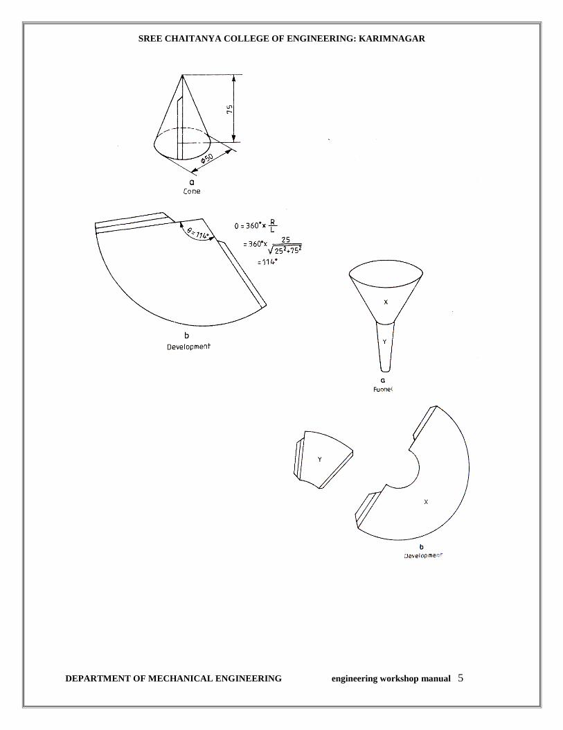
CONE
Expt. No.:3
AIM: To make a cone
APPARATUS TOOLS REQUIRED:
300 mm steel rule, divider, protractor, scriber, straight and bent snips, protractor, mallet and
funnel stake.
MATERIAL REQUIRED : G.I. SHEET
PROCEDURE:
1. The size of the given sheet is checked with a steel rule.
2. The development of the cone is marked on the given sheet by using scriber.
3. The angle subtended by the arc of the sector is calculated from the relation,
θ = 360o x radius of the base circle of the cone / slant height .
4. The allowance for folding and bending is added to the development
5. The waste metal is cut-away by using the straight and bent snips.
6. The development of the cone is folded by using the funnel stake, after forming the single
hemmed joint.
SAFETY PRECAUTIONS:
1. Avoid feeling the cut portion by hand while cutting with snip.
2. Do not let sheet metal slip through your hands. Most cuts from sheet metal results from
allowing it to slide through the hands.
3. Use snips only for metal that can be cut by force applied by hand.
4. Hand snips should never be used to cut wires. Such practice ruins the cutting edges of the
blades.
RESULT: The cone is thus made, from the given sheet metal.
SREE CHAITANYA COLLEGE OF ENGINEERING: KARIMNAGAR
DEPARTMENT OF MECHANICAL ENGINEERING engineering workshop manual 5
SREE CHAITANYA COLLEGE OF ENGINEERING: KARIMNAGAR
DEPARTMENT OF MECHANICAL ENGINEERING engineering workshop manual 6
BLACK SMITHY
THEORY
Forge or Hearth:
A smith’s forge or hearth is used to heat the metal to be shaped. Hearths are used for heating
small jobs to be forged by hand. Gas, oil or coal firing may be used for the purpose. The
required air for the fire is supplied under pressure, by a blower through the tuyer in the hearth.
The blowers may either be hand operated or power driven. In the latter case, the amount of air
supply is controlled by valves near the forge. The rod, shown in figure, collects gases of
combustion and sends through a chimney. The following are the forging temperatures of various
metals.
S.No. Material Forging temperature Range
(in oC)
1. Mild steel 750-1300
2. Wrought iron 900-1300
3. Medium carbon steel 750-1250
4. High carbon and alloy steel 800-1150
Heating of a metal to proper temperature is essential as excessive temperature may result in
burning of the metal that destroys cohesion between atoms. Insufficient temperature will not
induce sufficient plasticity to the metal, to shape is properly by hammering. Insufficient
temperature also results in cold working defects like strain hardening and cracking.
Anvil:
It provides the necessary support during forging by resisting the heavy blows rendered to the job.
It is also useful for operations such as bending, swaging, etc. Its body is generally made of cast
steel, wrought iron or mild steel, with a hardened top layer of about 20 to 25 mm thick. The beak
or horn in used for bending metal to round shape of different radii. The portion between the beak
and face is called ledge, which is used for bending round rods and as a die for hot punching
operation. Anvils are made in sizes weighing from 25kg to 250kg. An anvil weighing about 75
kg is suitable for general purpose.
Swage Block:
It is also a supporting tool used in a forge shop. It has a number of slots of different shapes and
sizes along its four side faces and through holes of different shapes and sizes, running from its
top to bottom faces. This is used as a support while forming (swaging) different shapes, bending
and in punching holes. It is generally made of cast iron or cast steel.
Leg vice:
It is a heavy duty vice, fixed to the work bench at one end of a leg or set in a concrete base. It is
SREE CHAITANYA COLLEGE OF ENGINEERING: KARIMNAGAR
DEPARTMENT OF MECHANICAL ENGINEERING engineering workshop manual 7
mainly used for light forging and bending work.
Hammers:
Hammers of different types and weights are used in smithy. The ball-peen hammer used for
forging, weighs 0.5kg to 0kg. The sledge hammer which is used for heavy work, has flat ends on
either side and weighs 3 kg to 8kg. The length of the handle of a hammer increases with its
weight.
Tongs:
The metal to be forged must be held securely, while it is being shaped. A pair of tongs of
suitable size and shape must be used for the purpose. They are made of mild steel and the sizes
vary from 40 cm to 60 cm in length and 0.6 cm to 5.5cm opening.
A flat bit tongs can hold the job along the entire length of its jaws. It is used for holding work of
rectangular section. Round bit tongs is used for holding a round rod. Square bit tongs is used for
holding a square rod. Pick-up tongs is used for pick-up the heated rods from the hearth.

SREE CHAITANYA COLLEGE OF ENGINEERING: KARIMNAGAR
DEPARTMENT OF MECHANICAL ENGINEERING engineering workshop manual 8

SREE CHAITANYA COLLEGE OF ENGINEERING: KARIMNAGAR
DEPARTMENT OF MECHANICAL ENGINEERING engineering workshop manual 9
REVIEW QUESTIONS:
1 What is meant by smithy?
2. What are the various stages of hand forging to get the desired shape?
3 What are the advantages of forging?
4 Differentiate between hand forging and machine forging.
5 Describe an open hearth coal fired furnace, along with its working principle.
6 What for the ‘ledge’ part of the anvil is used?
7 What for swage block is used in a smithy shop?
8 Classify the tongs and their applications.
9 What is meant by ‘Drawing-down’, as applied to a process in a smithy section.
10 Define the following terms, as applied to smithy shop:
a. Upsetting
b. Fullering
c. Swaging
11 With what, the fuller size is denoted?
12 Differentiate between ‘hot’ and ‘cold’ chisels.
13 What are the purposes of heat treating the forgings?
SREE CHAITANYA COLLEGE OF ENGINEERING: KARIMNAGAR
DEPARTMENT OF MECHANICAL ENGINEERING engineering workshop manual 10
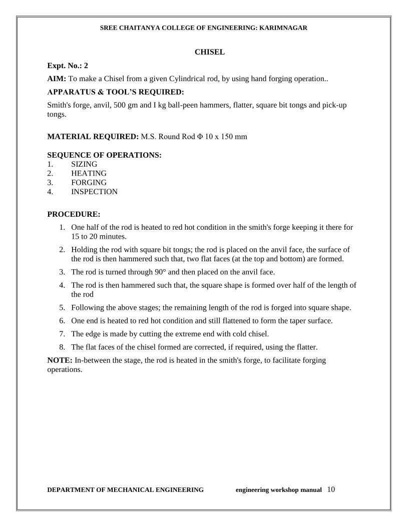
CHISEL
Expt. No.: 2
AIM: To make a Chisel from a given Cylindrical rod, by using hand forging operation..
APPARATUS & TOOL’S REQUIRED:
Smith's forge, anvil, 500 gm and I kg ball-peen hammers, flatter, square bit tongs and pick-up
tongs.
MATERIAL REQUIRED: M.S. Round Rod Φ 10 x 150 mm
SEQUENCE OF OPERATIONS:
1. SIZING
2. HEATING
3. FORGING
4. INSPECTION
PROCEDURE:
1. One half of the rod is heated to red hot condition in the smith's forge keeping it there for
15 to 20 minutes.
2. Holding the rod with square bit tongs; the rod is placed on the anvil face, the surface of
the rod is then hammered such that, two flat faces (at the top and bottom) are formed.
3. The rod is turned through 90° and then placed on the anvil face.
4. The rod is then hammered such that, the square shape is formed over half of the length of
the rod
5. Following the above stages; the remaining length of the rod is forged into square shape.
6. One end is heated to red hot condition and still flattened to form the taper surface.
7. The edge is made by cutting the extreme end with cold chisel.
8. The flat faces of the chisel formed are corrected, if required, using the flatter.
NOTE: In-between the stage, the rod is heated in the smith's forge, to facilitate forging
operations.
SREE CHAITANYA COLLEGE OF ENGINEERING: KARIMNAGAR
DEPARTMENT OF MECHANICAL ENGINEERING engineering workshop manual 11
SAFETY PRECAUTIONS:
1. Hold the hot work down wards close to the ground close to the ground, while transferring
the piece from hearth to anvil, to minimize the danger of burns, resulting from collision
with the others.
2. Use the correct size and type of tongs to fit the work. These should fit the work securely
to prevent its bouncing out of control from repetitive hammer blows.
3. Care should be exercised in the use of hammer. The minimum force should be used and
the flat face should strike squarely on the work.
4. Wear gloves when handling hot metal
5. Ensure that hammers are fitted with tight and wedged handles
RESULT: The chisel is thus made from the given cylindrical rod

SREE CHAITANYA COLLEGE OF ENGINEERING: KARIMNAGAR
DEPARTMENT OF MECHANICAL ENGINEERING engineering workshop manual 12
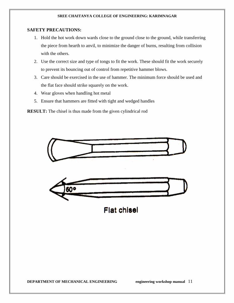
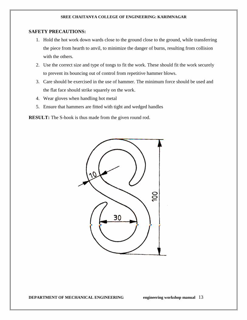
S-HOOK
Expt. No.: 3
AIM: To make S-hook
APPARATUS & TOOLS REQUIRED:
Smith's forge, anvil, 500 gm ball-peen hammer, flatters, swage block, half-round tongs and pick-
up tongs.
MATERIAL REQUIRED: M.S. Round Rod Φ 10 x 150 mm
SEQUENCE OF OPERATIONS:
1. SIZING
2. HEATING
3. FORGING
4. INSPECTION
PROCEDURE:
1. Using the pick-up tongs; the rod is taken from the forge, and holding it with the half-
round tongs, the heated end is forged into a tapered pointed end (keeping it there for
15 to 20 minutes).
2. The length of the rod required for S-hook is estimated and the excess portion is cut
off, using a cold chisel
3. One half of the rod towards the pointed end is heated in the forge to red hot condition
and then bent into circular shape as shown.
4. The other end of the rod is then heated and forged into a tapered pointed end.
5. The straight portion of the rod is finally heated and bent into circular shape as
required.
6. Using the flatter, the S-hook made as above, is kept on the anvil and flattened so that,
the shape of the hook is proper
NOTE: In-between the above stage, the bar is heated in the smith's forge, to facilitate forging
operations.
SREE CHAITANYA COLLEGE OF ENGINEERING: KARIMNAGAR
DEPARTMENT OF MECHANICAL ENGINEERING engineering workshop manual 13
SAFETY PRECAUTIONS:
1. Hold the hot work down wards close to the ground close to the ground, while transferring
the piece from hearth to anvil, to minimize the danger of burns, resulting from collision
with the others.
2. Use the correct size and type of tongs to fit the work. These should fit the work securely
to prevent its bouncing out of control from repetitive hammer blows.
3. Care should be exercised in the use of hammer. The minimum force should be used and
the flat face should strike squarely on the work.
4. Wear gloves when handling hot metal
5. Ensure that hammers are fitted with tight and wedged handles
RESULT: The S-hook is thus made from the given round rod.
SREE CHAITANYA COLLEGE OF ENGINEERING: KARIMNAGAR
DEPARTMENT OF MECHANICAL ENGINEERING engineering workshop manual 14
HOUSE WIRING
INTRODUCTION:
Power is supplied to domestic installations through a phase and a neutral, forming a single phase
A.C 230 V, two-wire system. For industrial establishments, power is supplied through three-
phase four wire system, to give 440 V. Fig shows the power tapping for domestic and industrial
purposes. The neutral is earthed at the distribution sub-station of the supply.
When supplied to domestic utilities, power is fed to a kilowatt meter and then to a
distribution panel. The panel distributes power along several circuits. It also protects these
circuits from overload by safety devices like fuses or circuit breakers. The panel also serves as a
main switch.
As a safe practice, all single-phase devices such as switches, fuses, etc., are connected to the live
conductor. All electrical conducto0rs and cables are color coded and must be correctly
connected-up. Electrical wiring is defined as a system of electric conductors, components and
apparatus for conveying electric power from the source to the point of use. The wiring system
must be designed to provided a constant voltage to the load.
ELEMENTS OF HOUSE WIRING:
Fuses and Circuit Breakers: These are the devices designed to provide protection to a
circuit against excess current. In old type of distribution panels, open link fuses, plug or cartridge
fuses were used. In newer panels, circuit breakers are used. If something goes wrong with an
appliance or supply, the line becomes overloaded or short-circuited. Then, either the fuse blows-
out or circuit breaker trips open, isolating that circuit or appliance. In such cases, the appliance
must be checked for defects or it must be ensured that there are not too many appliances in that
particular circuit.
Open link fuses are not safe in operation, even though they are cheaper and reliable. It consists
of a thin strip of metal or wire. Here, when the fuse blows-off due to heavy current in the circuit,
the metal is spilled around. A modified version of it consists of a porcelain fuse link, backing the
wire safely.
Though the plug fuse confines the molten metal thrown out while blowing, it is not very accurate
in operation. The length of the element also is very short. The cartridge fuse of non-renewable
type, encloses the fuse element in a fiber tube with a non-inflammable material. During the
blowing-off, the arc produced is chilled by the non-inflammable material. In case of a renewable
type, a cheap renewable fuse material is used in the cartridge.
The trouble with fuses is that they must be replaced once they burn away, whereas the circuit
breaker can be reset after the original condition is established. An electromagnetic circuit is
shown. A set of switch contacts inside the circuit breaker is normally kept closed by an armature.
When too much current flows through the coil, the armature is attracted, breaking the circuit.
The circuit breaker may be reset by a toggle lever.
Electric Switch: This is a device that makes and breaks or changes the course of electric
circuit. It consists of two or more contacts mounted on a n insulating structure and arranged such

SREE CHAITANYA COLLEGE OF ENGINEERING: KARIMNAGAR
DEPARTMENT OF MECHANICAL ENGINEERING engineering workshop manual 15
that, they may be moved into and out of contact with each other by a suitable operating
mechanism.
Plug: t is a device, carrying two or three metallic contacts in the form of pins, intended for
engaging with corresponding socket contacts and arranged for attachment to appliances such as
radio, T.V, table fan, etc.
Socket Outlet: It is a device, carrying two or three contacts, designed for engagement with
the corresponding plug pins and arranged for connection to fixed wiring.
Lamp Holder: amp holder are designed to hold lamps and connect them in the circuit.
Both bayonet cap and screw lamp holder are available upto 200 W lamps.
Ceiling Rose: A ceiling rose consists of a circular base and a cover made of bakelite.
The base has two or three terminal plates. One end of the plates is connected to supply and the
other end, to flexible wire connected to pendant lamp, ceiling fan, exhaust fan etc.
Main Switch: This is a switch intended to connect or cut-off the supply of electricity to
the whole of an installation. It is generally of metal clad type. The metal clad type gives greater
strength and safety. The main switch contains one or more fuses. Iron clad double pole switched
are used for single phase A.C circuits.

SREE CHAITANYA COLLEGE OF ENGINEERING: KARIMNAGAR
DEPARTMENT OF MECHANICAL ENGINEERING engineering workshop manual 16
REVIEW QUESTIONS:
1. Define electric wiring.
2. Name the safety devices used to protect the electric circuits from overload.
3. Name the various types of fuses.
4. Differentiate between a fuse and a circuit breaker.
5. What for a lamp holder is used in an electric circuit?
6. Name the types of lamp holders available in the market.
7. What for a ceiling rose is used?
8. Name the different forms of interior wiring.
9. What is meant by6 an electric circuit?
10. Name the three types of electrical circuits.
11. What are the places where “One lamp with independent control from two places”, is used?
12. Name the motor driven household appliances.
13. Name the household appliances, which are of heating type.
14. What for a circuit breaker is used?
15. What are the precautions to be taken, while connecting the wires with electrical
accessories?
16. Define the term “Earthing” or “Grounding”.
17. Name the different methods of earthing.
18. Classify the fans. What are the commonly used types of fans that are working on A.C.
power supply?
19. What are the precautions to be taken while installing a new ceiling fan?
20. Explain the principle of operation of an automatic electric iron.
21. Explain the principle of operation of a sodium vapor lamp.
22. What is the principle behind the operation of standby power supply?
23. What is the difference between emergency lamp and indicator lamp?
SREE CHAITANYA COLLEGE OF ENGINEERING: KARIMNAGAR
DEPARTMENT OF MECHANICAL ENGINEERING engineering workshop manual 17
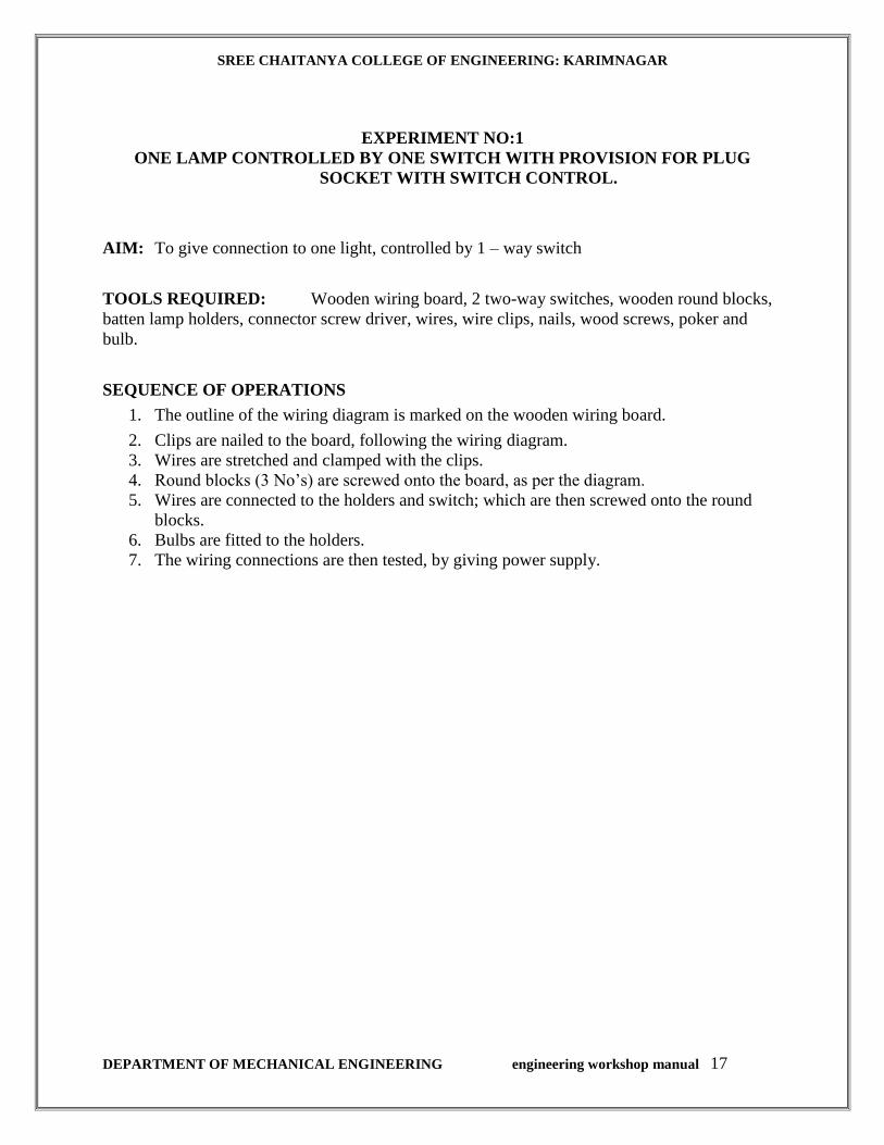
EXPERIMENT NO:1
ONE LAMP CONTROLLED BY ONE SWITCH WITH PROVISION FOR PLUG
SOCKET WITH SWITCH CONTROL.
AIM: To give connection to one light, controlled by 1 – way switch
TOOLS REQUIRED: Wooden wiring board, 2 two-way switches, wooden round blocks,
batten lamp holders, connector screw driver, wires, wire clips, nails, wood screws, poker and
bulb.
SEQUENCE OF OPERATIONS
1. The outline of the wiring diagram is marked on the wooden wiring board.
2. Clips are nailed to the board, following the wiring diagram.
3. Wires are stretched and clamped with the clips.
4. Round blocks (3 No’s) are screwed onto the board, as per the diagram.
5. Wires are connected to the holders and switch; which are then screwed onto the round
blocks.
6. Bulbs are fitted to the holders.
7. The wiring connections are then tested, by giving power supply.
SREE CHAITANYA COLLEGE OF ENGINEERING: KARIMNAGAR
DEPARTMENT OF MECHANICAL ENGINEERING engineering workshop manual 18
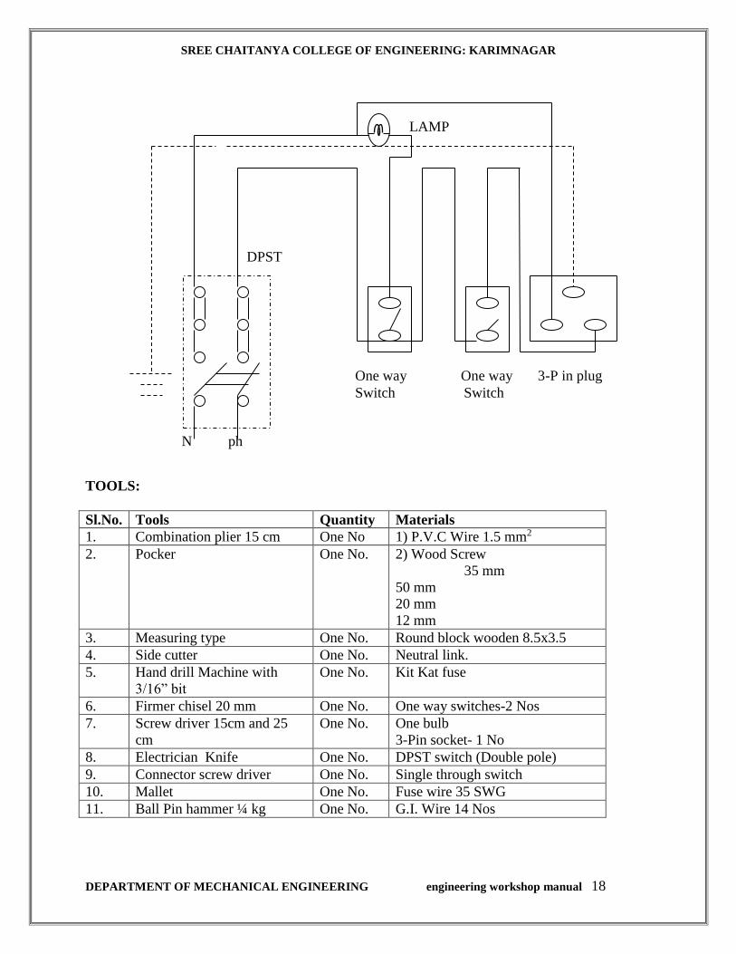
TOOLS:
Sl.No. Tools Quantity Materials
1. Combination plier 15 cm One No 1) P.V.C Wire 1.5 mm2
2. Pocker One No. 2) Wood Screw
35 mm
50 mm
20 mm
12 mm
3. Measuring type One No. Round block wooden 8.5x3.5
4. Side cutter One No. Neutral link.
5. Hand drill Machine with
3/16” bit
One No. Kit Kat fuse
6. Firmer chisel 20 mm One No. One way switches-2 Nos
7. Screw driver 15cm and 25
cm
One No. One bulb
3-Pin socket- 1 No
8. Electrician Knife One No. DPST switch (Double pole)
9. Connector screw driver One No. Single through switch
10. Mallet One No. Fuse wire 35 SWG
11. Ball Pin hammer ¼ kg One No. G.I. Wire 14 Nos
DPST
N ph
One way One way 3-P in plug
Switch Switch
LAMP

SREE CHAITANYA COLLEGE OF ENGINEERING: KARIMNAGAR
DEPARTMENT OF MECHANICAL ENGINEERING engineering workshop manual 19
PROCEDURE:
1) Make the circuit diagram and get it checked
2) With the help of plum bob draw straight lines on the board according to
the layout diagram.
3) With the help of scale mark the lines according to the given size
4) Make guide holes for cleats at proper places
5) Fix the cleats loosely
6) Draw the wires into the cleats and tighten the screws of cleats.
7) Make holes in the blocks and boards for holder and switches and pass
the wire through these holes.
8) Fix the blocks and boards with two screws on each block and board
9) Fix the switch and holders etc, by doing proper connections
10) Check the wiring with series test lamp or Megger
RESULT:
SREE CHAITANYA COLLEGE OF ENGINEERING: KARIMNAGAR
DEPARTMENT OF MECHANICAL ENGINEERING engineering workshop manual 20
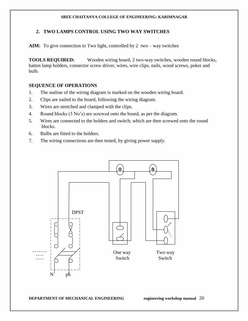
2. TWO LAMPS CONTROL USING TWO WAY SWITCHES
AIM: To give connection to Two light, controlled by 2 two – way switches
TOOLS REQUIRED: Wooden wiring board, 2 two-way switches, wooden round blocks,
batten lamp holders, connector screw driver, wires, wire clips, nails, wood screws, poker and
bulb.
SEQUENCE OF OPERATIONS
1. The outline of the wiring diagram is marked on the wooden wiring board.
2. Clips are nailed to the board, following the wiring diagram.
3. Wires are stretched and clamped with the clips.
4. Round blocks (3 No’s) are screwed onto the board, as per the diagram.
5. Wires are connected to the holders and switch; which are then screwed onto the round
blocks.
6. Bulbs are fitted to the holders.
7. The wiring connections are then tested, by giving power supply.
DPST
N ph
One way Two way
Switch Switch
SREE CHAITANYA COLLEGE OF ENGINEERING: KARIMNAGAR
DEPARTMENT OF MECHANICAL ENGINEERING engineering workshop manual 21
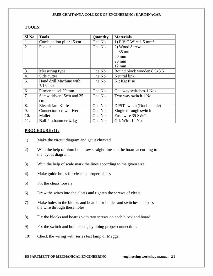
TOOLS:
Sl.No. Tools Quantity Materials
1. Combination plier 15 cm One No 1) P.V.C Wire 1.5 mm2
2. Pocker One No. 2) Wood Screw
35 mm
50 mm
20 mm
12 mm
3. Measuring type One No. Round block wooden 8.5x3.5
4. Side cutter One No. Neutral link.
5. Hand drill Machine with
3/16” bit
One No. Kit Kat fuse
6. Firmer chisel 20 mm One No. One way switches-1 Nos
7. Screw driver 15cm and 25
cm
One No. Two way switch 1 No
8. Electrician Knife One No. DPST switch (Double pole)
9. Connector screw driver One No. Single through switch
10. Mallet One No. Fuse wire 35 SWG
11. Ball Pin hammer ¼ kg One No. G.I. Wire 14 Nos
PROCEDURE (1) :
1) Make the circuit diagram and get it checked
2) With the help of plum bob draw straight lines on the board according to
the layout diagram.
3) With the help of scale mark the lines according to the given size
4) Make guide holes for cleats at proper places
5) Fix the cleats loosely
6) Draw the wires into the cleats and tighten the screws of cleats.
7) Make holes in the blocks and boards for holder and switches and pass
the wire through these holes.
8) Fix the blocks and boards with two screws on each block and board
9) Fix the switch and holders etc, by doing proper connections
10) Check the wiring with series test lamp or Megger

SREE CHAITANYA COLLEGE OF ENGINEERING: KARIMNAGAR
DEPARTMENT OF MECHANICAL ENGINEERING engineering workshop manual 22
PROCEDURE (2) :
1. S1 down S2 up – Both off
2. S1 down S2 down – L1 on
3. S1 up S2 up – Both parallel
4. S1 down S2 down-L1L2 series
FOUR CONDITIONS
1. Both off 2. One lamp L1 bright
3. Both parallel (bright) 4. Both in series (dim)
If the switch is put in the circuit as shown fig. fifth condition can be obtained I,e only L2 will be
on.
RESULT:
SREE CHAITANYA COLLEGE OF ENGINEERING: KARIMNAGAR
DEPARTMENT OF MECHANICAL ENGINEERING engineering workshop manual 23
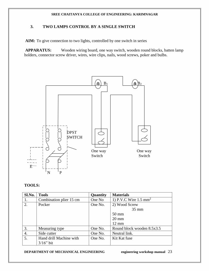
3. TWO LAMPS CONTROL BY A SINGLE SWITCH
AIM: To give connection to two lights, controlled by one switch in series
APPARATUS: Wooden wiring board, one way switch, wooden round blocks, batten lamp
holders, connector screw driver, wires, wire clips, nails, wood screws, poker and bulbs.
TOOLS:
Sl.No. Tools Quantity Materials
1. Combination plier 15 cm One No 1) P.V.C Wire 1.5 mm2
2. Pocker One No. 2) Wood Screw
35 mm
50 mm
20 mm
12 mm
3. Measuring type One No. Round block wooden 8.5x3.5
4. Side cutter One No. Neutral link.
5. Hand drill Machine with
3/16” bit
One No. Kit Kat fuse
DPST
SWITCH
N P
One way One way
Switch Switch
E
B1 B2

SREE CHAITANYA COLLEGE OF ENGINEERING: KARIMNAGAR
DEPARTMENT OF MECHANICAL ENGINEERING engineering workshop manual 24
6. Firmer chisel 20 mm One No. One way switches-2 Nos
7. Screw driver 15cm and 25
cm
One No. Two Bulbs
8. Electrician Knife One No. DPST switch (Double pole)
9. Connector screw driver One No. Single through switch
10. Mallet One No. Fuse wire 35 SWG
11. Ball Pin hammer ¼ kg One No. G.I. Wire 14 Nos
PROCEDURE:
1) Make the circuit diagram and get it checked
2) With the help of plum bob draw straight lines on the board according to
the layout diagram.
3) With the help of scale mark the lines according to the given size
4) Make guide holes for cleats at proper places
5) Fix the cleats loosely
6) Draw the wires into the cleats and tighten the screws of cleats.
7) Make holes in the blocks and boards for holder and switches and pass
the wire through these holes.
8) Fix the blocks and boards with two screws on each block and board
9) Fix the switch and holders etc, by doing proper connections
10) Check the wiring with series test lamp or Megger
RESULT:
SREE CHAITANYA COLLEGE OF ENGINEERING: KARIMNAGAR
DEPARTMENT OF MECHANICAL ENGINEERING engineering workshop manual 25
FOUNDRY
THEORY
SPECIFICATIONS:
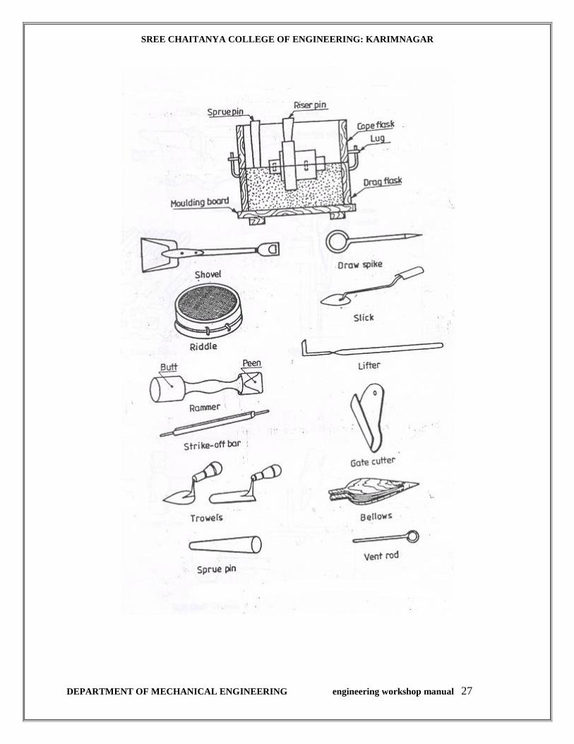
The tools and equipment needed for molding are: Molding board, molding flasks (boxes),
bellows, shovel, riddle and molder’s tools.
Trowel: It consists of a metal blade fitted into a wooden handle. It is used to smoothen the surface of the
mould. It may also be used for repairing the damaged portion of the mold. Trowels are made in
many different styles and sizes, each one suitable for a particular job.
Spike or Draw Pin:
If is a pointed steel rod with a loop at the other end. It is used to remove the pattern from the
mould. A draw screw, with a threaded end, may also be used for the purpose.
Slick:
It is a small double ended tool having a flat on one end and a spoon on the other. It is used for
mending and finishing small surfaces of the mold.
Lifters:
Lifters are made of thin sections of steel of various widths and lengths, with one end bent at right
angles. These are used for cleaning and finishing the bottom and sides of the deep and narrow
pockets of the mold.
Gate Cutter:
It is a semicircular piece of tin sheet, used to cut gates in the mould. Gates are meant for easy
flow of molten metal into the mould.
NOTE A gate is a channel made on the surface of the drag, to connect the sprue hole to the mold
cavity. The size of the gate depends upon the size of the mold cavity.
Bellows:
It is a hand tool, used to blow air, to remove the loose sand particles from the mold cavity.
Vent Rod:
It is a thin rod used for making vents or holes in the sand mould to allow the escape of mould
gases generated during the pouring of molten metal. .

SREE CHAITANYA COLLEGE OF ENGINEERING: KARIMNAGAR
DEPARTMENT OF MECHANICAL ENGINEERING engineering workshop manual 26
NOTE:
(i) To make a mold with a split pattern, half of the pattern is rammed-up first in the drag.
After inverting the drag and placing the cope in position, place the other half of the
pattern over the first half and repeat the rest of the molding procedure. When two pieces
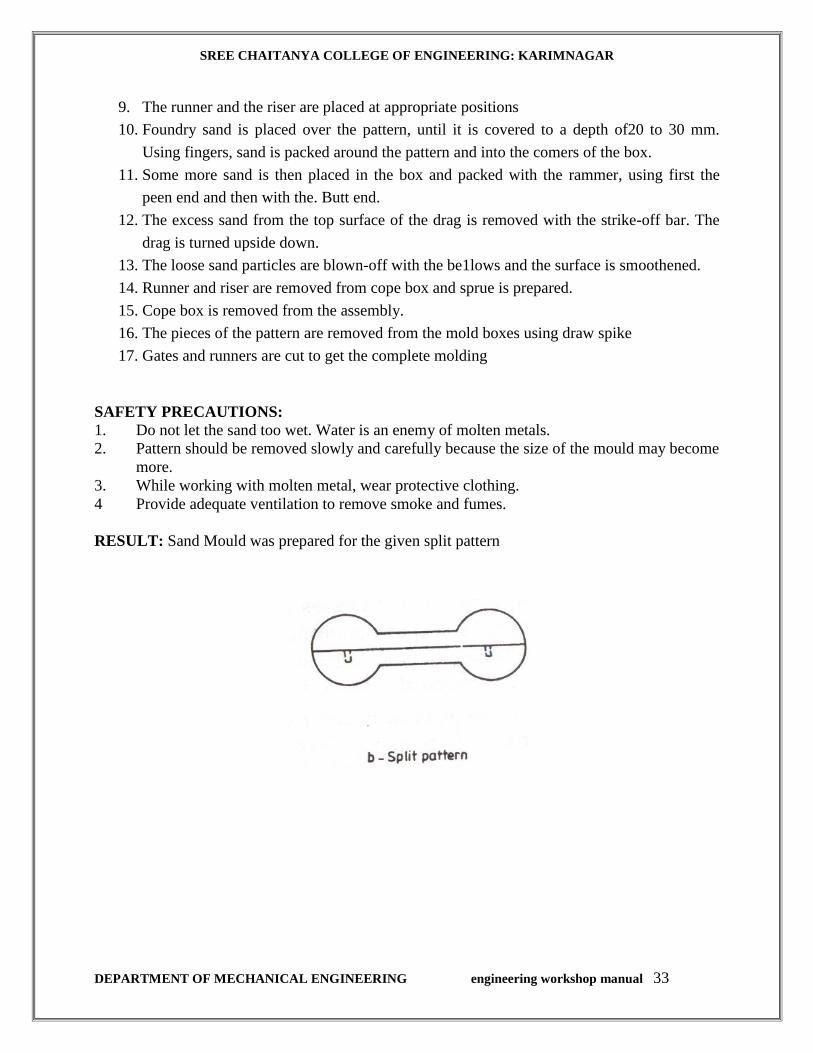
of the split pattern are different in sizes, place the largest piece in the drag. Figure 11.4
shows a mold with split or two piece pattern.
(ii) To make a mold with three piece pattern; after completing the drag work, place the
middle part of the pattern in position and complete the ramming in cheek before placing
the cope and the last part of the pattern. shows the method of molding a three-piece
pattern.
(iii) In machine molding, packing / ramming the sand, lifting the pattern, etc., are done by
mechanical devices, operated pneumatically.
SREE CHAITANYA COLLEGE OF ENGINEERING: KARIMNAGAR
DEPARTMENT OF MECHANICAL ENGINEERING engineering workshop manual 27
SREE CHAITANYA COLLEGE OF ENGINEERING: KARIMNAGAR
DEPARTMENT OF MECHANICAL ENGINEERING engineering workshop manual 28
Foundry practice deals with the process of making castings in moulds, formed in either sand or
some other material. The process involves the operations of pattern making, sand preparation,
molding, melting of metals, pouring in moulds, cooling, shake-out, fettling, heat treatment,
finishing and inspection.
NOTE: Casting is the process of making parts by pouring the molten metal into moulds
and allowing them to solidify.
There is no limit to the size and shape of the article to be produced by the casting process. It also
offers one of the easiest and most economical methods of producing intricate parts.
Mould is a cavity formed by a pattern. It is similar in shape and size to that of the actual casting
plus some allowances for shrinkage, machining, etc. Molding is the process of making moulds.
Moulds are classified as temporary and permanent. Temporary moulds are made of refractory
sand and other binding materials and may be produced either through hand molding or machine
molding. Permanent moulds are made of ferrous metals and alloys, i.e., cast iron, steel, etc.
In this chapter, manual methods of making green sand moulds are presented. The stages involved
in the sand molding process are: Sand preparation, pattern making, core making (if required),
molding and closing.
NOTE:(i) Melting furnaces convert the charge materials into the molten state by heating to a
temperature above their melting point. Melting furnaces can be fired on liquid,
solid or gaseous fuel or heated by electric energy.
(ii) For production requirements, cupola furnace is used for producing molten metal
(cast iron)
REVIEW QUESTIONS:
1 List-out the stages involved in a sand molding process.
2 List-out the various operations that are performed under "Foundry Practice".
3 What is a mold and what is meant by molding?
4 Classify the molds and their uses.
5 Differentiate between, "Natural molding sand" and "Synthetic sand".
6 List-out the various types of synthetic binders used in molding sands.
7 What is the part played by binders in molding sand?
8 What is a pattern?
9 What are the various types of patterns that are used in practice?
10 What is a core print?
11 What are the points to be considered while designing a pattern?
12 What is a molding board?
13. What for a draw pin -is used in the molding process?

SREE CHAITANYA COLLEGE OF ENGINEERING: KARIMNAGAR
DEPARTMENT OF MECHANICAL ENGINEERING engineering workshop manual 29
A SOLID FLANGE (SINGLE PIECE PATTERN)
Expt No.: 1
AIM: To prepare a sand mold cavity of solid flange (single piece pattern).
APPARATUS & TOOLS REQUIRED:
Molding board, drag and cope boxes, molding sand, parting sand, rammer. Strike-off bar,
bellows, riser and sprue pins, gate cutter, vent rod and draw spike.
MATERIAL REQUIRED: Moulding sand, parting sand, bentonite, water.
MOULDING COMPOSITION:
Silica Sand – 80 to 90%
Clay – 10 to 12%
Water – 8 to 10%
Additives - 2 to 4%
SEQUENCE OF OPERATIONS:
1. FILLING
2. RAMMING
3. STRIKE-OFF
4. INSPECTION
PROCEDURE:
1. The pattern is placed on the molding board, with its flat side on the board.
2. The drag box is placed over the board, after giving it a clay wash inside.
3. Parting sand is sprinkled over the pattern and the molding board.
4. Foundry sand is placed over the pattern, until it is covered to a depth of 20 to 30 mm.
5. Using fingers, sand is packed around the pattern and into the corners of the box.
6. Some more sand is then placed in the box and packed with the rammer, using first, the
peen end and then with the butt end.
7. The excess sand from the top surface of the drag is removed by striking-off with the
strike-off bar
8. The drag is turned upside down.
SREE CHAITANYA COLLEGE OF ENGINEERING: KARIMNAGAR
DEPARTMENT OF MECHANICAL ENGINEERING engineering workshop manual 30
9. The loose sand particles are blown-off with the bellows and the surface is
smoothened.
10. The cope box is placed in position on top of the drag box, after giving it a clay was
inside. The riser pin is then located on the surface of the pattern.
11. The sprue pin is placed at about 50 to 60 mm from the pattern, but on the opposite
side of the riser pin.
12. Parting sand is sprinkled on the upper surface.
13. Steps 4 to 7 are repeated, appropriately (Fig)
14. Using a vent rod, holes are made to about 10 mm from the pattern.
15. The sprue and riser pins are removed, by carefully drawing them out. A funnel
shaped hole is made at the top of the sprue hole, called pouring basin/cup.
16. The cope is lifted and placed aside on its edge.
17. A draw spike is inserted into the pattern and the edges around the pattern are wetted.
Then the pattern is loosened by tapping, and then drawn straight up (Fig)
18. The mold is repaired by adding bits of sand, wherever the mold is found defective.
19. Using a gate cutter, a gate is cut in the drag, from the sprue to the mold.
20. The loose sand particles that are present in the mold are blown-off.
21. The mold is finally closed by replacing the cope on the drag and placing weights on it
SAFETY PRECAUTIONS:
1. Do not let the sand too wet. Water is an enemy of molten metals.
2. Pattern should be removed slowly and carefully because the size of the mould may
become more.
3. While working with molten metal, wear protective clothing.
4. Provide adequate ventilation to remove smoke and fumes.
RESULT: The sand mold for a solid flange is thus made, which is ready for pouring the
molten metal.

SREE CHAITANYA COLLEGE OF ENGINEERING: KARIMNAGAR
DEPARTMENT OF MECHANICAL ENGINEERING engineering workshop manual 31

SREE CHAITANYA COLLEGE OF ENGINEERING: KARIMNAGAR
DEPARTMENT OF MECHANICAL ENGINEERING engineering workshop manual 32
STEPPED GROVE PULLEY (SPLIT PATTERN)
EXPT NO.: 2
AIM: To prepare a sand Mould cavity for stepped groove pulley:
APPARATUS & TOOLS REQUIRED:
Molding board, drag and cope boxes, molding sand, parting sand, rammer, strike-off bar,
bellows, riser and sprue pins, gate cutter, vent rod and draw spike.
MATERIAL REQUIRED: Moulding sand, parting sand, bentonite, water.
MOULDING COMPOSITION:
Silica Sand – 80 to 90%
Clay – 10 to 12%
Water – 8 to 10%
Additives - 2 to 4%
SEQUENCE OF OPERATIONS:
1. FILLING
2. RAMMING
3. STRIKE-OFF
4. INSPECTION
PROCEDURE:
1. One half of the pattern is placed on the molding board with its flat side on the board.
2. The drag box is placed over the board, after giving it a clay wash inside. Parting sand is
sprinkled over the pattern and the molding board.
3. Foundry sand is placed over the pattern, until it is covered to a depth of20 to 30 mm.
Using fingers, sand is packed around the pattern and into the comers of the box.
4. Some more sand is then placed in the box and packed with the rammer, using first the
peen end and then with the Butt end.
5. The excess sand from the top surface of the drag is removed with the strike-off bar. The
drag is turned upside down.
6. The loose sand particles are blown-off with the be1lows and the surface is smoothened.
7. The second half of the pattern is located over the first half, using the dowel pins.
8. The cope box is placed in position on top of the drag box, after giving it a clay wash
SREE CHAITANYA COLLEGE OF ENGINEERING: KARIMNAGAR
DEPARTMENT OF MECHANICAL ENGINEERING engineering workshop manual 33
9. The runner and the riser are placed at appropriate positions
10. Foundry sand is placed over the pattern, until it is covered to a depth of20 to 30 mm.
Using fingers, sand is packed around the pattern and into the comers of the box.
11. Some more sand is then placed in the box and packed with the rammer, using first the
peen end and then with the. Butt end.
12. The excess sand from the top surface of the drag is removed with the strike-off bar. The
drag is turned upside down.
13. The loose sand particles are blown-off with the be1lows and the surface is smoothened.
14. Runner and riser are removed from cope box and sprue is prepared.
15. Cope box is removed from the assembly.
16. The pieces of the pattern are removed from the mold boxes using draw spike
17. Gates and runners are cut to get the complete molding
SAFETY PRECAUTIONS:
1. Do not let the sand too wet. Water is an enemy of molten metals.
2. Pattern should be removed slowly and carefully because the size of the mould may become
more.
3. While working with molten metal, wear protective clothing.
4 Provide adequate ventilation to remove smoke and fumes.
RESULT: Sand Mould was prepared for the given split pattern
SREE CHAITANYA COLLEGE OF ENGINEERING: KARIMNAGAR
DEPARTMENT OF MECHANICAL ENGINEERING engineering workshop manual 34
GROOVED PULLEY
EXPT NO.:3
AIM: To prepare a sand mold cavity of a grooved pulley. (split pattern with core)
Note: Groove pulley is used as an element in power transmission through V – belt drive.
APPARATUS&TOOLS REQUIRED:
Molding board, drag and cope boxes, core box, molding sand, core sand, parting sand, rammer,
strike-off bar, bellows, riser and sprue pins, gate cutter, vent rod and draw spike.
MATERIAL REQUIRED: Moulding sand, parting sand, bentonite, water.
MOULDING COMPOSITION:
Silica Sand – 80 to 90%
Clay – 10 to 12%
Water – 8 to 10%
Additives - 2 to 4%
SEQUENCE OF OPERATIONS:
1. FILLING
2. RAMMING
3. STRIKE-OFF
4. INSPECTION
PROCEDURE:
1. Using the core box and core sand, the core is prepared and kept aside safely.
2. One half of the pattern is placed on the molding board with its flat side on the board.
3. The drag box is placed over the board, after giving it a clay wash inside.
4. Parting sand is sprinkled over the pattern and the molding board.
5. Foundry sand is placed over the pattern, until it is covered to a depth of 20 to 30 mm.
6. Using fingers, sand is packed around the pattern and into the corners of the box.
7. Some more sand is then placed in the box and packed with the rammer, using first, the
peen end and then with the butt end.
SREE CHAITANYA COLLEGE OF ENGINEERING: KARIMNAGAR
DEPARTMENT OF MECHANICAL ENGINEERING engineering workshop manual 35
Note: As the height of the pattern is more compared to its lateral dimension; the sand
around the pattern must be packed, using fingers till the pattern is covered with the sand.
8. The excess sand from the top surface of the drag is removed by strike-off bar
9. The drag is turned upside down.
10. The loose sand particles are blown-off with the bellows and the surface is
smoothened.
11. The second half of the pattern is located over the first half, using the dowel pins.
12. The cope box is placed in position on top of the drag box, after giving it a clay was
inside. The riser pin is then located on the surface of the pattern.
13. The sprue pin is placed at about 50 to 60 mm from the pattern, but on the opposite
side of the riser pin.
14. Parting sand is sprinkled on the upper surface.
15. Steps 5 to 8 are repeated, appropriately
16. Using a vent rod, holes are made to about 10 mm from the pattern.
17. The sprue and riser pins are removed, by carefully drawing them out. A funnel
shaped hole is made at the top of the sprue hole, called pouring basin/cup.
18. The cope is lifted and placed upside down on another molding board.
19. Using a draw spike and wetting the edges around the split pattern in both the molding
boxes, the patterns are loosened by tapping and then drawn straight up.
20. The mold is repaired by adding bits of sand, wherever the mold is found defective.
21. Using a gate cutter, a gate is cut in the drag, from the sprue to the mold cavity.
22. The loose sand particles that are present in the mold are blown-off.
23. The core is positioned in the mold cavity carefully.
24. The mold is finally closed by replacing the cope on the drag and placing weights on it
(Fig)
SAFETY PRECAUTIONS:
1 Do not let the sand too wet. Water is an enemy of molten metals.
2 Pattern should be removed slowly and carefully because the size of the mould may
become more.
3 While working with molten metal, wear protective clothing.
4 Provide adequate ventilation to remove smoke and fumes.
RESULT: The sand mold for the grooved pulley is thus made, which is ready for during the
molten metal.
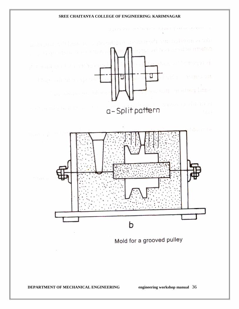
SREE CHAITANYA COLLEGE OF ENGINEERING: KARIMNAGAR
DEPARTMENT OF MECHANICAL ENGINEERING engineering workshop manual 36
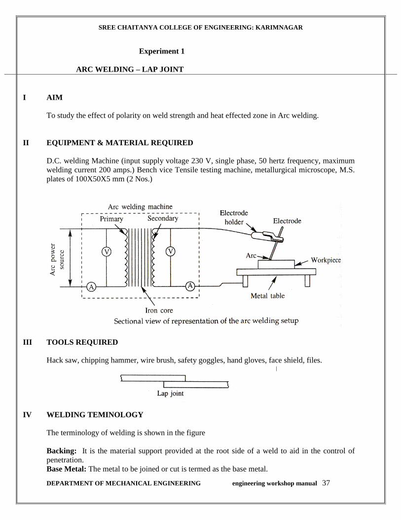
SREE CHAITANYA COLLEGE OF ENGINEERING: KARIMNAGAR
DEPARTMENT OF MECHANICAL ENGINEERING engineering workshop manual 37
Experiment 1
ARC WELDING – LAP JOINT
I AIM
To study the effect of polarity on weld strength and heat effected zone in Arc welding.
II EQUIPMENT & MATERIAL REQUIRED
D.C. welding Machine (input supply voltage 230 V, single phase, 50 hertz frequency, maximum
welding current 200 amps.) Bench vice Tensile testing machine, metallurgical microscope, M.S.
plates of 100X50X5 mm (2 Nos.)
III TOOLS REQUIRED
Hack saw, chipping hammer, wire brush, safety goggles, hand gloves, face shield, files.
IV WELDING TEMINOLOGY
The terminology of welding is shown in the figure
Backing: It is the material support provided at the root side of a weld to aid in the control of
penetration.
Base Metal: The metal to be joined or cut is termed as the base metal.

SREE CHAITANYA COLLEGE OF ENGINEERING: KARIMNAGAR
DEPARTMENT OF MECHANICAL ENGINEERING engineering workshop manual 38
Bead or weld bead: Bead is the metal added during a single pass of welding. The bead appears as
a separate material from the base metal.
Crater: In are welding, a crater is the depression in the weld metal pool at the pint where the are
strikes the base metal plate.
Deposition rate: The rate at which the weld metal is deposited per unit time, is the deposition
rate and is normally expressed as kg/h.
Fillet weld: The meal fused into the corner of a joint made of two pieces placed at
approximately 900 to each other is termed fillet weld.
Penetration: It is the depth up to which the weld metal combines with the base metal as
measured from the top surface of the joint.
Puddle: The portion of these weld joint that melted by the heat of welding is called puddle.
Root: It is the point at which the two pieces to be joined by welding are nearest.
Tach Weld: A small weld, generally used to temporally hold the two pieces, together during
actual welding, is the tack weld.
Weld face: It is the exposed surface of the weld.
Weld metal: The metal that is solidified in the joint is called weld metal. It may be only base
metal or a mixture of base metal and filler metal.
Weld pass: A single movement of the welding torch or electrode along the length of the joint
which results in a bead, is a weld pass.
V DESCRIPTION
Principle of Arc: An arc is generated between two conductors of electricity, cathode and anode
(considering direct current, DC), when they are touched to establish the flow of current and then
separated by a small distance. An arc is a sustained electric discharge through the ionized gas
column called plasma between the two electrodes. Electrons liberated from the cathode move
towards the anode and are accelerated in their movement. When they strike the anode at high
velocity, large amount of heat is generated. In order to produce the arc the potential difference
between the two electrodes should be sufficient to allow them to move across the air gap. The
larger air gap requires higher potential differences. If the air gap becomes to large for the voltage
the arc may be extinguished.
Straight and Reverse Polarity: When more heat is required at the work piece side for welding
thicker sheets or for the work materials which have high thermal conductivity such as aluminum
and copper the work is made as anode liberating the large heat near it. This is termed as straight

SREE CHAITANYA COLLEGE OF ENGINEERING: KARIMNAGAR
DEPARTMENT OF MECHANICAL ENGINEERING engineering workshop manual 39
polarity or DCEN. This gives rise to higher penetration required in thick work pieces. However
for the thinner materials where less heat is required in the weld zone the polarity is reversed
making the work negative. This is termed as reversed polarity or DCEP. In reverse polarity the
penetration is small.
Selection of Electrodes: The electrodes for welding operation should be selected properly
depending on the requirements of the welding. The main points to be considered are
1. The composition of the base metal which determines the electrode composition.
2. The tensile strength of the required joint.
3. The thickness of the base metal. For thinner metals the current setting should be lower.
4. The required metal deposition rate.
5. The type of the arc welding equipment used.
6. The weld position (flat, horizontal, vertical, overhead.) A flat position can accommodate
large size electrode.
The electrodes are marked with six digits numeral associated by a prefix, and suffix. The
meaning of these and various values it can take is shown in the figure.
Electrode sizes based on metal thickness to be welded is given in the table shown below:
Weld Position Metal thickness
(mm)
Electrode diameter
(mm)
Root Electrode
diameter (mm)
All 3 to 6 3.2 -
Down hand
6
9
12
12
16
16
20 to 25
4
6
8
6
8
6
9
-
4
4
5
5
5
5
Vertical
6
8 to 12
16 to 20
25
3.24
5
5
-
3.2
4
5
Weld
Position
Metal thickness
(mm)
Electrode
Diameter (mm)
Root Electrode
Diameter (mm)
Horizontal
6 to 9
12 to 20
25
4
6
6
3.2
4
5
Heat Affected Zone: A heat effected zone (HAZ) of a weld is the part of welded joint which has
been heated to temperature up to the solidus of the parent material resulting in varying degree of
micro structure as a consequence of heating and cooling cycle. When the metals and alloys
without polymorphous transformation (Cu, Ni, Ai) are welded, the micro structure in the HAZ
remains unaltered through grain growth or recrystalization may takes place, while in the case of
metals and alloys with polymorphous transformation (steels ) significant microstructure changes
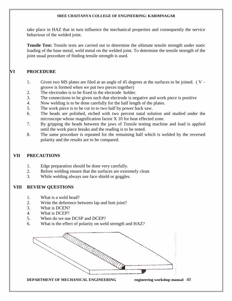
SREE CHAITANYA COLLEGE OF ENGINEERING: KARIMNAGAR
DEPARTMENT OF MECHANICAL ENGINEERING engineering workshop manual 40
take place in HAZ that in turn influence the mechanical properties and consequently the service
behaviour of the welded joint.
Tensile Test: Tensile tests are carried out to determine the ultimate tensile strength under static
loading of the base metal, weld metal on the welded joint. To determine the tensile strength of the
joint usual procedure of finding tensile strength is used.
VI PROCEDURE
1. Given two MS plates are filed at an angle of 45 degrees at the surfaces to be joined. ( V –
groove is formed when we put two pieces together)
2. The electrodes is to be fixed in the electrode holder.
3. The connections to be given such that electrode is negative and work piece is positive
4. Now welding is to be done carefully for the half length of the plates.
5. The work piece is to be cut in to two half by power hack saw.
6. The beads are polished, etched with two percent natal solution and studied under the
microscope whose magnification factor X 10 for heat effected zone.
7. By gripping the beads between the jaws of Tensile testing machine and load is applied
until the work piece breaks and the reading is to be noted.
8. The same procedure is repeated for the remaining half which is welded by the reversed
polarity and the results are to be compared.
VII PRECAUTIONS
1. Edge preparation should be done very carefully.
2. Before welding ensure that the surfaces are extremely clean
3. While welding always use face shield or goggles.
VIII REVIEW QUESTIONS
1. What is a weld bead?
2. Write the deference between lap and butt joint?
3. What is DCEN?
4. What is DCEP?
5. When do we use DCSP and DCEP?
6. What is the effect of polarity on weld strength and HAZ?
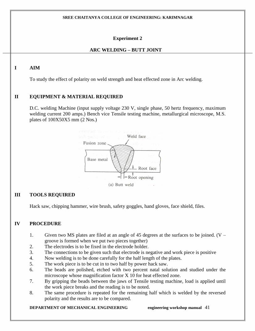
SREE CHAITANYA COLLEGE OF ENGINEERING: KARIMNAGAR
DEPARTMENT OF MECHANICAL ENGINEERING engineering workshop manual 41
Experiment 2
ARC WELDING – BUTT JOINT
I AIM
To study the effect of polarity on weld strength and heat effected zone in Arc welding.
II EQUIPMENT & MATERIAL REQUIRED
D.C. welding Machine (input supply voltage 230 V, single phase, 50 hertz frequency, maximum
welding current 200 amps.) Bench vice Tensile testing machine, metallurgical microscope, M.S.
plates of 100X50X5 mm (2 Nos.)
III TOOLS REQUIRED
Hack saw, chipping hammer, wire brush, safety goggles, hand gloves, face shield, files.
IV PROCEDURE
1. Given two MS plates are filed at an angle of 45 degrees at the surfaces to be joined. (V –
groove is formed when we put two pieces together)
2. The electrodes is to be fixed in the electrode holder.
3. The connections to be given such that electrode is negative and work piece is positive
4. Now welding is to be done carefully for the half length of the plates.
5. The work piece is to be cut in to two half by power hack saw.
6. The beads are polished, etched with two percent natal solution and studied under the
microscope whose magnification factor X 10 for heat effected zone.
7. By gripping the beads between the jaws of Tensile testing machine, load is applied until
the work piece breaks and the reading is to be noted.
8. The same procedure is repeated for the remaining half which is welded by the reversed
polarity and the results are to be compared.
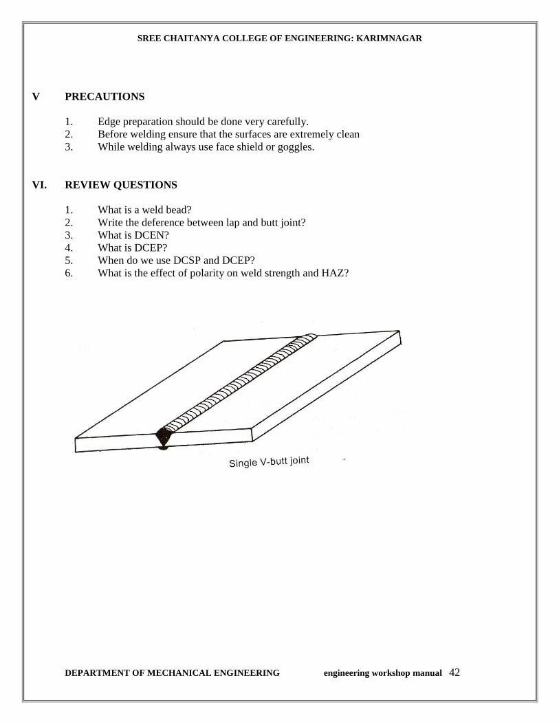
SREE CHAITANYA COLLEGE OF ENGINEERING: KARIMNAGAR
DEPARTMENT OF MECHANICAL ENGINEERING engineering workshop manual 42
V PRECAUTIONS
1. Edge preparation should be done very carefully.
2. Before welding ensure that the surfaces are extremely clean
3. While welding always use face shield or goggles.
VI. REVIEW QUESTIONS
1. What is a weld bead?
2. Write the deference between lap and butt joint?
3. What is DCEN?
4. What is DCEP?
5. When do we use DCSP and DCEP?
6. What is the effect of polarity on weld strength and HAZ?
SREE CHAITANYA COLLEGE OF ENGINEERING: KARIMNAGAR
DEPARTMENT OF MECHANICAL ENGINEERING engineering workshop manual 43
WOOD WORKING
Introduction
Wood turning has had a definite place in the commercial world for a great many years. It is used
in various forms in making furniture and furniture parts, building trim, tool parts, toys, athletic
paraphernalia and many other useful and beautiful articles in common use.
THE LATHE
The sizes of turning lathes are given as 10", 12", etc. These figures denote the diameter, or size,
of the largest piece of work that can be turned on them. The measurement is taken from the center
point of the live center to the bed of the lathe (usually 5" or 6") and is one-half the diameter of the
entire circle. The length of a lathe is determined by the length of a piece of work that can be
turned. This measurement is taken from the points of the live and dead centers when the tail stock
is drawn back the full extent of the lathe bed. Fig. 1 shows a turning lathe with sixteen principal
parts named. The student should learn the names of these parts and familiarize himself with the
particular function of each.
CARE OF THE LATHE
The lathe should be oiled every day before starting. At the end of the period the lathe should be
brushed clean of all chips and shavings, after which it should be rubbed off with a piece of waste
or cloth to remove all surplus oil. All tools should be wiped clean and put in their proper places.
If a student finds that his lathe is not running as it should, he should first call the attention of the
instructor to that fact before attempting to adjust it; and then only such adjustments should be
made as the instructor directs.
SPEED OF THE LATHE
The speed of the lathe should range from 2400 to 3000 revolutions per minute when the belt is on
the smallest step of the cone pulley. At this speed stock up to 3" in diameter can be turned with
safety. Stock from 3" to 6" in diameter should be turned on the second or third step, and all stock
over 6" on the last step. The speed at which a lathe should run depends entirely upon the nature of
the work to be done and the kind of material used. Pieces that cannot be centered accurately and
all glued-up work with rough corners should be run slowly until all corners are taken off and the
stock runs true. At high speed the centrifugal force on such pieces is very great, causing the lathe
to vibrate, and there is a possibility of the piece being thrown from the lathe thus endangering the
worker as well as those around him. After the stock is running true the speed may be increased.

SREE CHAITANYA COLLEGE OF ENGINEERING: KARIMNAGAR
DEPARTMENT OF MECHANICAL ENGINEERING engineering workshop manual 44
Fig. 1. - Wood Turning Lathe
SREE CHAITANYA COLLEGE OF ENGINEERING: KARIMNAGAR
DEPARTMENT OF MECHANICAL ENGINEERING engineering workshop manual 45
WOOD TURNING TOOLS
A wood turning kit should consist of one each of the following tools. Fig. 2 shows the general
shape of these tools.
1¼"Gouge
¾"Gouge
½"Gouge
¼"Gouge
1¼"Skew
¾"Skew
½"Skew
¼"Skew
⅛"Parting Tool
½"RoundNose
¼"RoundNose
½"SquareNose
¼"SquareNose
½"SpearPoin
½"RightSkew
½"LeftSkew
Slip Stone with round edges
6"InsideCalipers
8"Dividers
12"Rule
½pt.OilCan
Bench Brush
GRINDING AND WHETTING TURNING TOOLS
Skew Chisel
The skew chisel is sharpened equally on both sides On this tool the cutting edge should form an
angle of about 20° with one of the edges. The skew is used in cutting both to the right and to the
left, and therefore, must be beveled on both sides. The length of the bevel should equal about
twice the thickness of the chisel at the point where it is sharpened. In grinding the bevel, the
chisel must be held so that the cutting edge will be parallel to the axis of the emery wheel. The
wheel should be about 6" in diameter as this will leave the bevel slightly hollow ground. Cool the
chisel in water occasionally when using a dry emery. Otherwise the wheel will burn the chisel,
taking out the temper; the metal will be soft and the edge will not stand up. Care should be
exercised that the same bevel is kept so that it will be uniformly hollow ground. The rough edge
left by the emery wheel should be whetted off with a slip stone by holding the chisel on the flat
side of the stone so that the toe and heel of the bevel are equally in contact with it. Rub first on
one side and then on the other. The wire edge is thus worn off quickly as there is no metal to be
worn away in the middle of the bevels. The chisel is sharp when the edge, which may be tested
by drawing it over the thumb nail, is smooth and will take hold evenly along its entire length. If
any wire edge remains it should be whetted again.
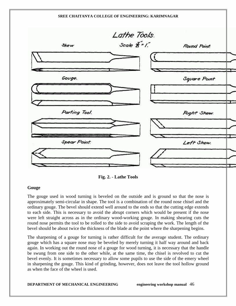
SREE CHAITANYA COLLEGE OF ENGINEERING: KARIMNAGAR
DEPARTMENT OF MECHANICAL ENGINEERING engineering workshop manual 46
Fig. 2. - Lathe Tools
Gouge
The gouge used in wood turning is beveled on the outside and is ground so that the nose is
approximately semi-circular in shape. The tool is a combination of the round nose chisel and the
ordinary gouge. The bevel should extend well around to the ends so that the cutting edge extends
to each side. This is necessary to avoid the abrupt corners which would be present if the nose
were left straight across as in the ordinary wood-working gouge. In making shearing cuts the
round nose permits the tool to be rolled to the side to avoid scraping the work. The length of the
bevel should be about twice the thickness of the blade at the point where the sharpening begins.
The sharpening of a gouge for turning is rather difficult for the average student. The ordinary
gouge which has a square nose may be beveled by merely turning it half way around and back
again. In working out the round nose of a gouge for wood turning, it is necessary that the handle
be swung from one side to the other while, at the same time, the chisel is revolved to cut the
bevel evenly. It is sometimes necessary to allow some pupils to use the side of the emery wheel
in sharpening the gouge. This kind of grinding, however, does not leave the tool hollow ground
as when the face of the wheel is used.
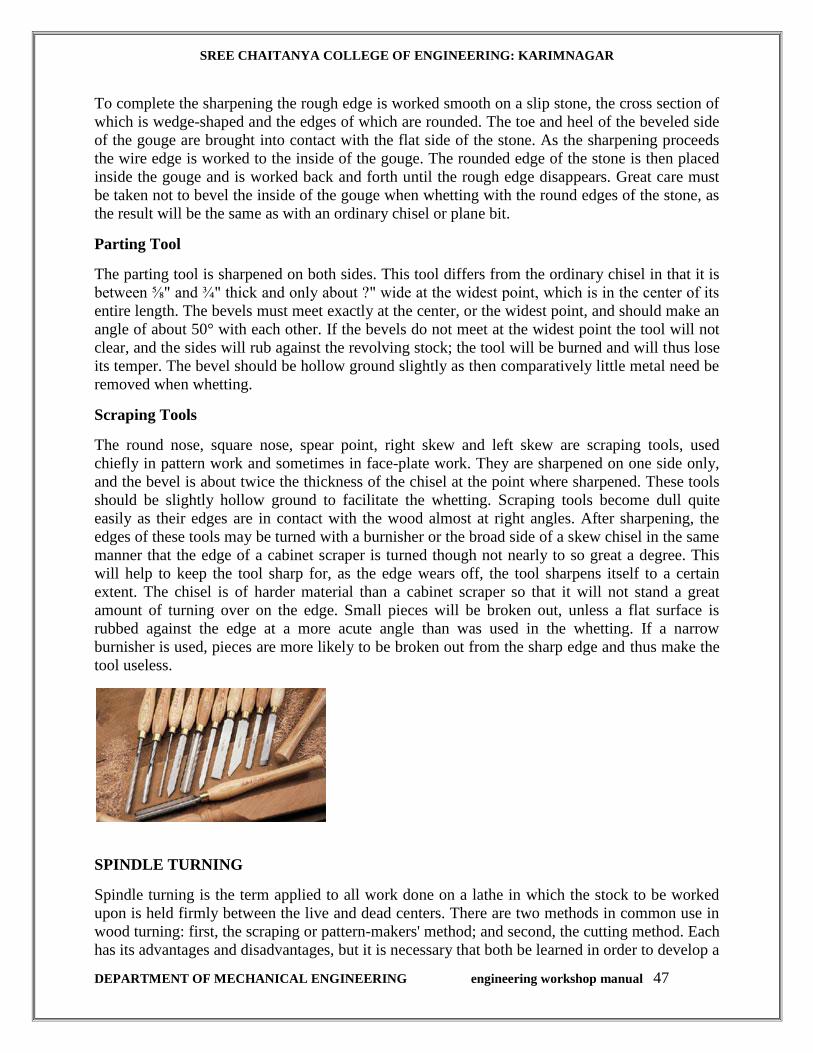
SREE CHAITANYA COLLEGE OF ENGINEERING: KARIMNAGAR
DEPARTMENT OF MECHANICAL ENGINEERING engineering workshop manual 47
To complete the sharpening the rough edge is worked smooth on a slip stone, the cross section of
which is wedge-shaped and the edges of which are rounded. The toe and heel of the beveled side
of the gouge are brought into contact with the flat side of the stone. As the sharpening proceeds
the wire edge is worked to the inside of the gouge. The rounded edge of the stone is then placed
inside the gouge and is worked back and forth until the rough edge disappears. Great care must
be taken not to bevel the inside of the gouge when whetting with the round edges of the stone, as
the result will be the same as with an ordinary chisel or plane bit.
Parting Tool
The parting tool is sharpened on both sides. This tool differs from the ordinary chisel in that it is
between ⅝" and ¾" thick and only about ?" wide at the widest point, which is in the center of its
entire length. The bevels must meet exactly at the center, or the widest point, and should make an
angle of about 50° with each other. If the bevels do not meet at the widest point the tool will not
clear, and the sides will rub against the revolving stock; the tool will be burned and will thus lose
its temper. The bevel should be hollow ground slightly as then comparatively little metal need be
removed when whetting.
Scraping Tools
The round nose, square nose, spear point, right skew and left skew are scraping tools, used
chiefly in pattern work and sometimes in face-plate work. They are sharpened on one side only,
and the bevel is about twice the thickness of the chisel at the point where sharpened. These tools
should be slightly hollow ground to facilitate the whetting. Scraping tools become dull quite
easily as their edges are in contact with the wood almost at right angles. After sharpening, the
edges of these tools may be turned with a burnisher or the broad side of a skew chisel in the same
manner that the edge of a cabinet scraper is turned though not nearly to so great a degree. This
will help to keep the tool sharp for, as the edge wears off, the tool sharpens itself to a certain
extent. The chisel is of harder material than a cabinet scraper so that it will not stand a great
amount of turning over on the edge. Small pieces will be broken out, unless a flat surface is
rubbed against the edge at a more acute angle than was used in the whetting. If a narrow
burnisher is used, pieces are more likely to be broken out from the sharp edge and thus make the
tool useless.
SPINDLE TURNING
Spindle turning is the term applied to all work done on a lathe in which the stock to be worked
upon is held firmly between the live and dead centers. There are two methods in common use in
wood turning: first, the scraping or pattern-makers' method; and second, the cutting method. Each
has its advantages and disadvantages, but it is necessary that both be learned in order to develop a

SREE CHAITANYA COLLEGE OF ENGINEERING: KARIMNAGAR
DEPARTMENT OF MECHANICAL ENGINEERING engineering workshop manual 48
well rounded turner. Care should be exercised, however, that each method be used in its proper
place. The first is slower, harder on the cutting edge of tools, and less skill is required to obtain
accurate work; the second is faster, easier on the cutting edge of tools, and the accuracy of results
obtained depends upon the skill acquired. As skill is the one thing most sought for in high school
work, the use of the cutting method is advocated entirely for all spindle turning and, with but few
exceptions, for face-plate and chuck turning.
TO CENTER STOCK
If the wood to be turned is square or rectangular in shape the best way to locate the center is to
draw diagonals across the end of the stock. The point of intersection locates the center.
CLAMPING STOCK IN THE LATHE
Take the live center from the spindle and with a wooden mallet drive the spur deep into the wood.
Never drive the wood onto the live center while in the spindle because serious injury may be
done the machine by such practice. When extremely hard wood is being used, it is a good
practice to make saw cuts along the diagonal lines and bore a hole at the intersection, thus
allowing the spur to enter the wood more freely. Oil the other end of the wood while holding it in
a vertical position, and give the oil a chance to penetrate into the wood. Then replace the live
center by taking the stock and center and forcing it into the spindle by a sudden push of the hand.
The tail stock is then moved about ½" to 1" from the end of the piece to be turned, having the tail
spindle well back in the tail stock. The tail stock is then clamped to the lathe bed. Turn the tail
stock hand wheel until the wood is held firmly. Work the cone pulley by hand at the same time,
so that the cup or dead center will be forced deeply into the wood, so deeply that the live center
will not continue to turn. Now turn the dead spindle back until the live spindle begins to turn
freely and clamp the dead spindle fast.
Fig. 3
ADJUSTING THE TOOL REST

SREE CHAITANYA COLLEGE OF ENGINEERING: KARIMNAGAR
DEPARTMENT OF MECHANICAL ENGINEERING engineering workshop manual 49
Horizontally the tool rest should be set about ⅛" from the farthest projecting corner of the wood
and should be readjusted occasionally as the stock diminishes in size. The vertical height varies
slightly according to the height of the operator. It is even with the center of the spindle for a short
person; ⅛" above for a medium person; and ¼" above for a tall person. So long as the stock is in
its square form the tool rest should never be adjusted while the machine is in motion as there is
danger of the rest catching the corners and throwing the stock from the machine. Also see that
everything is clamped tight before starting the lathe.
POSITION OF THE OPERATOR
The operator stands firmly on the floor back far enough from the lathe to allow him to pass the
tools from right to left in front of his body without changing the position of the feet. It may be
found convenient to turn slightly, bringing the left side of the body a little closer to the lathe. In
no case, however, should the tools be brought in contact with the body as the cutting operation
from right to left should be accomplished by a movement of the arms alone and not the swaying
of the body. (Fig. 3.)
HOLDING THE TOOLS
All tools should be held firmly but not rigidly. The right hand should grasp the handle at the
extreme end for two reasons: first, to give as much leverage as possible so that the tool will not
be thrown from the hands in case it should catch in the wood; second, a slight wavering of the
hand will not cause as much variance in the cuts as when held closer up to the rest. The left hand
should act as a guide and should be held over the tool near the cutting edge. The little finger and
the back part of the palm of the hand should touch the tool rest thus assuring a steady movement.
The left hand should not grasp the tool at any time. (Fig. 3.)

SREE CHAITANYA COLLEGE OF ENGINEERING: KARIMNAGAR
DEPARTMENT OF MECHANICAL ENGINEERING engineering workshop manual 50
DUMBBELLS
Expt. No.:1
AIM: To make Dumbbells
TOOLS REQUIRED: Skew Chisel, Gouge, Parting Tool, Scraping Tools, Round point, square
point, and Right skew, left skew.
MATERIAL REQUIRED: wood pieces.
PROCEDURE
1. With the Power Switch in its “OFF” position and the Lathe unplugged from its electrical
outlet, make all necessary adjustments to the machine as previously discussed.
2. To set up a spindle turning operation, mark both ends of the workpiece by drawing
diagonal lines from corner to corner. The intersection point of these two lines will
indicate the center of the workpiece.
3. Use a wood mallet and punch to tap the point of the center of the workpiece so that it
leaves a center mark.
4. Use a 1/8” drill bit to drill a 3/16” deep hole at the center mark on the workpiece.
5. Cut the corners off the workpiece if it is over 2” x 2” to make turning safer and easier.
6. Use a wood mallet to drive the Headstock Spur Center into the center of the workpiece at
least 1/4” deep.
7. With the workpiece still attached, insert the Headstock Spur Center into the Headstock
Spindle.
8. With the Cup Center installed in the Tailstock, slide the Tailstock toward the workpiece
until the Cup Center touches the workpiece center point. The lock the Tailstock in
position.
9. Use the Tailstock Hand wheel to push the Cup Center into the workpiece at least 1/4”.
10. Position the Tool Rest approximately 1/4” away from the workpiece and approximately
1/8” above the center line.
11. Make sure to test the set up by hand turning the workpiece to ensure there is enough
clearance all the way around before starting.
12. Find the center of the workpiece in the same way as when spindle turning.
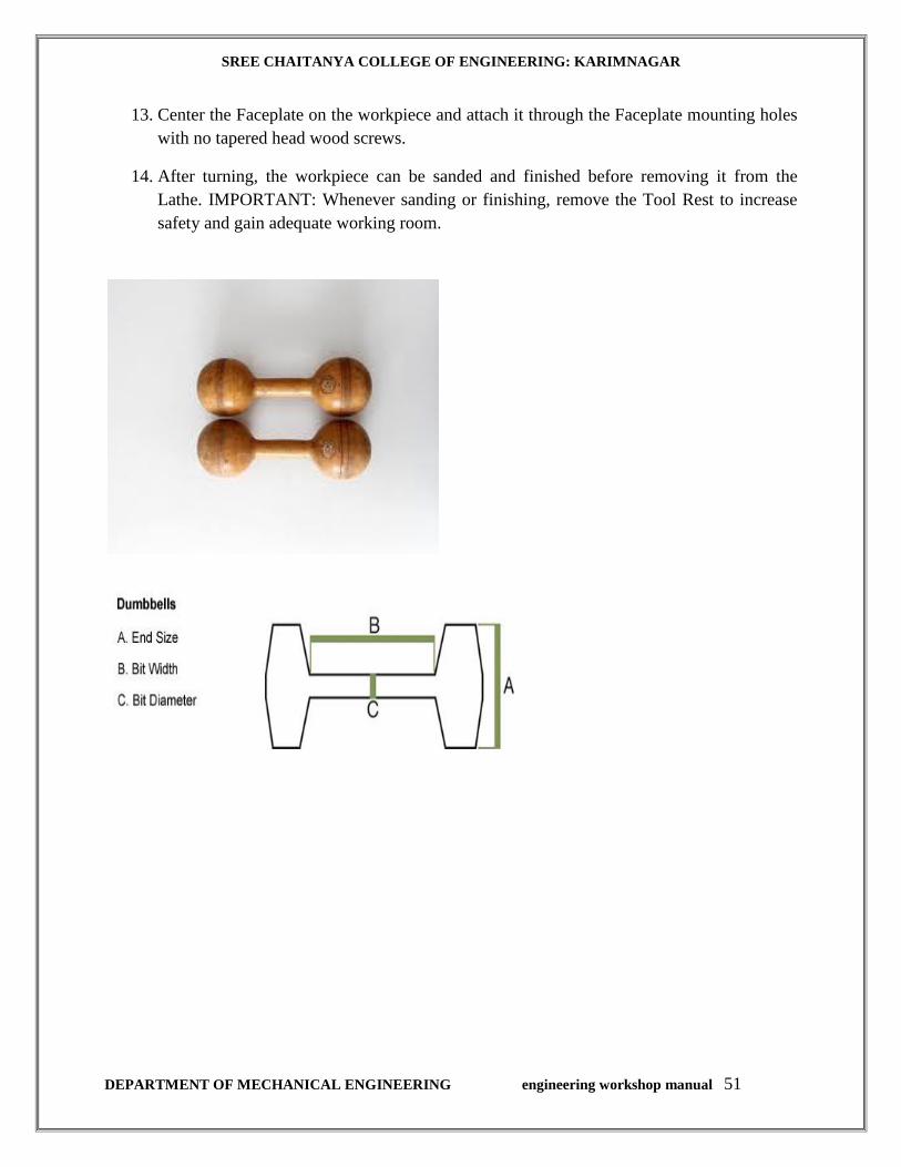
SREE CHAITANYA COLLEGE OF ENGINEERING: KARIMNAGAR
DEPARTMENT OF MECHANICAL ENGINEERING engineering workshop manual 51
13. Center the Faceplate on the workpiece and attach it through the Faceplate mounting holes
with no tapered head wood screws.
14. After turning, the workpiece can be sanded and finished before removing it from the
Lathe. IMPORTANT: Whenever sanding or finishing, remove the Tool Rest to increase
safety and gain adequate working room.

SREE CHAITANYA COLLEGE OF ENGINEERING: KARIMNAGAR
DEPARTMENT OF MECHANICAL ENGINEERING engineering workshop manual 52

SREE CHAITANYA COLLEGE OF ENGINEERING: KARIMNAGAR
DEPARTMENT OF MECHANICAL ENGINEERING engineering workshop manual 53

SREE CHAITANYA COLLEGE OF ENGINEERING: KARIMNAGAR
DEPARTMENT OF MECHANICAL ENGINEERING engineering workshop manual 54
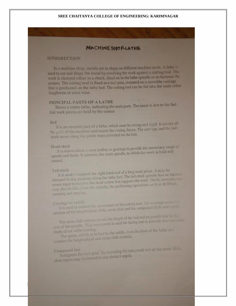
SREE CHAITANYA COLLEGE OF ENGINEERING: KARIMNAGAR
DEPARTMENT OF MECHANICAL ENGINEERING engineering workshop manual 55
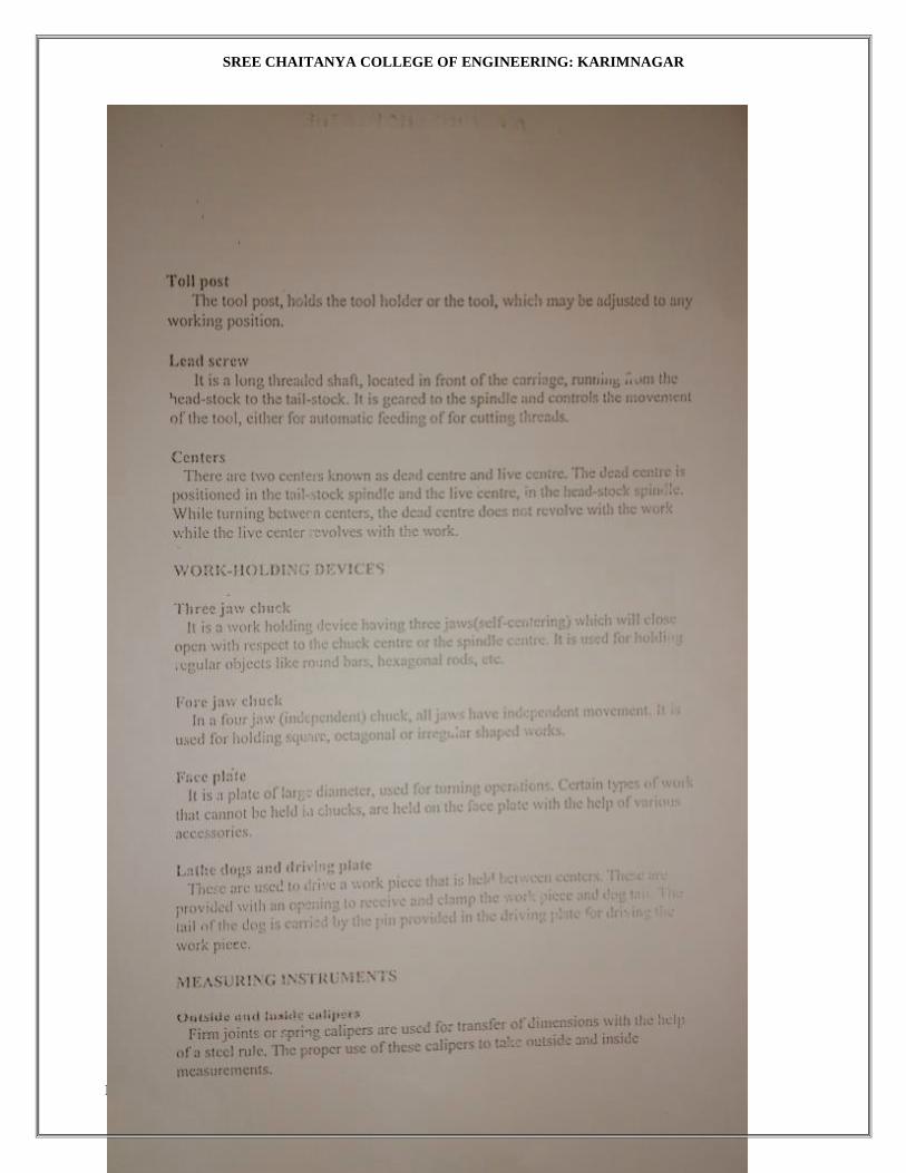
SREE CHAITANYA COLLEGE OF ENGINEERING: KARIMNAGAR
DEPARTMENT OF MECHANICAL ENGINEERING engineering workshop manual 56
SREE CHAITANYA COLLEGE OF ENGINEERING: KARIMNAGAR
DEPARTMENT OF MECHANICAL ENGINEERING engineering workshop manual 57

SREE CHAITANYA COLLEGE OF ENGINEERING: KARIMNAGAR
DEPARTMENT OF MECHANICAL ENGINEERING engineering workshop manual 58

SREE CHAITANYA COLLEGE OF ENGINEERING: KARIMNAGAR
DEPARTMENT OF MECHANICAL ENGINEERING engineering workshop manual 59
SREE CHAITANYA COLLEGE OF ENGINEERING: KARIMNAGAR
DEPARTMENT OF MECHANICAL ENGINEERING engineering workshop manual 60
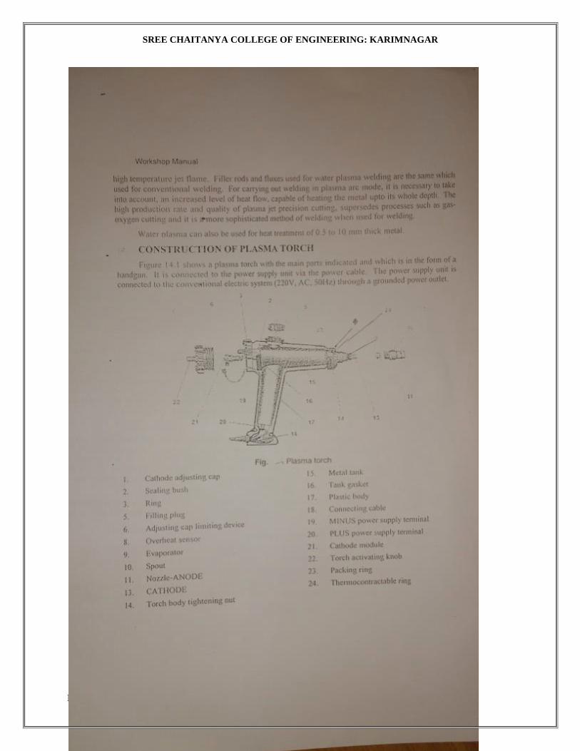
SREE CHAITANYA COLLEGE OF ENGINEERING: KARIMNAGAR
DEPARTMENT OF MECHANICAL ENGINEERING engineering workshop manual 61
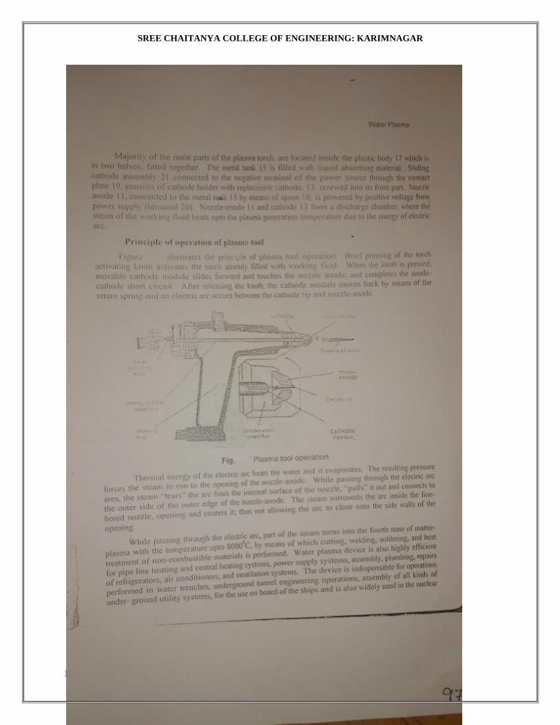
SREE CHAITANYA COLLEGE OF ENGINEERING: KARIMNAGAR
DEPARTMENT OF MECHANICAL ENGINEERING engineering workshop manual 62
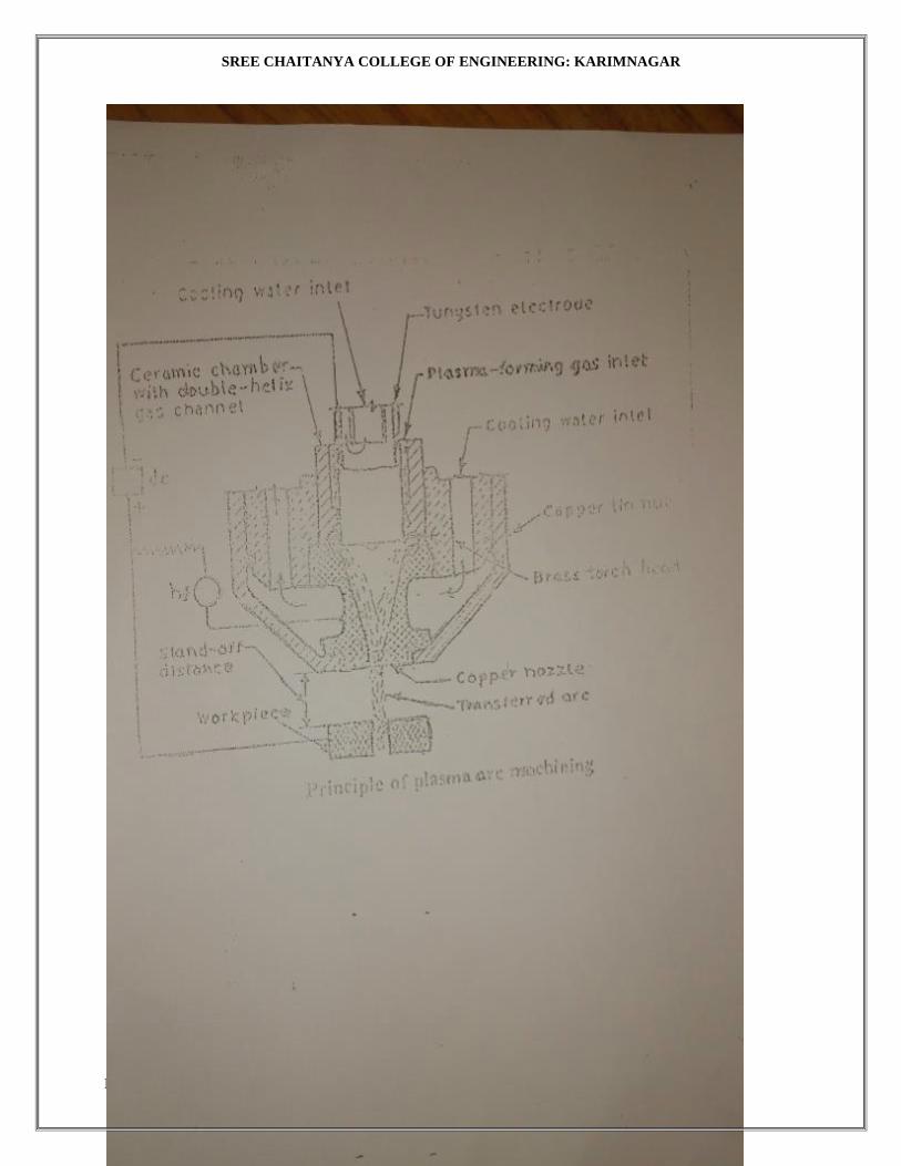
SREE CHAITANYA COLLEGE OF ENGINEERING: KARIMNAGAR
DEPARTMENT OF MECHANICAL ENGINEERING engineering workshop manual 63

SREE CHAITANYA COLLEGE OF ENGINEERING: KARIMNAGAR
DEPARTMENT OF MECHANICAL ENGINEERING engineering workshop manual 64

SREE CHAITANYA COLLEGE OF ENGINEERING: KARIMNAGAR
DEPARTMENT OF MECHANICAL ENGINEERING engineering workshop manual 65
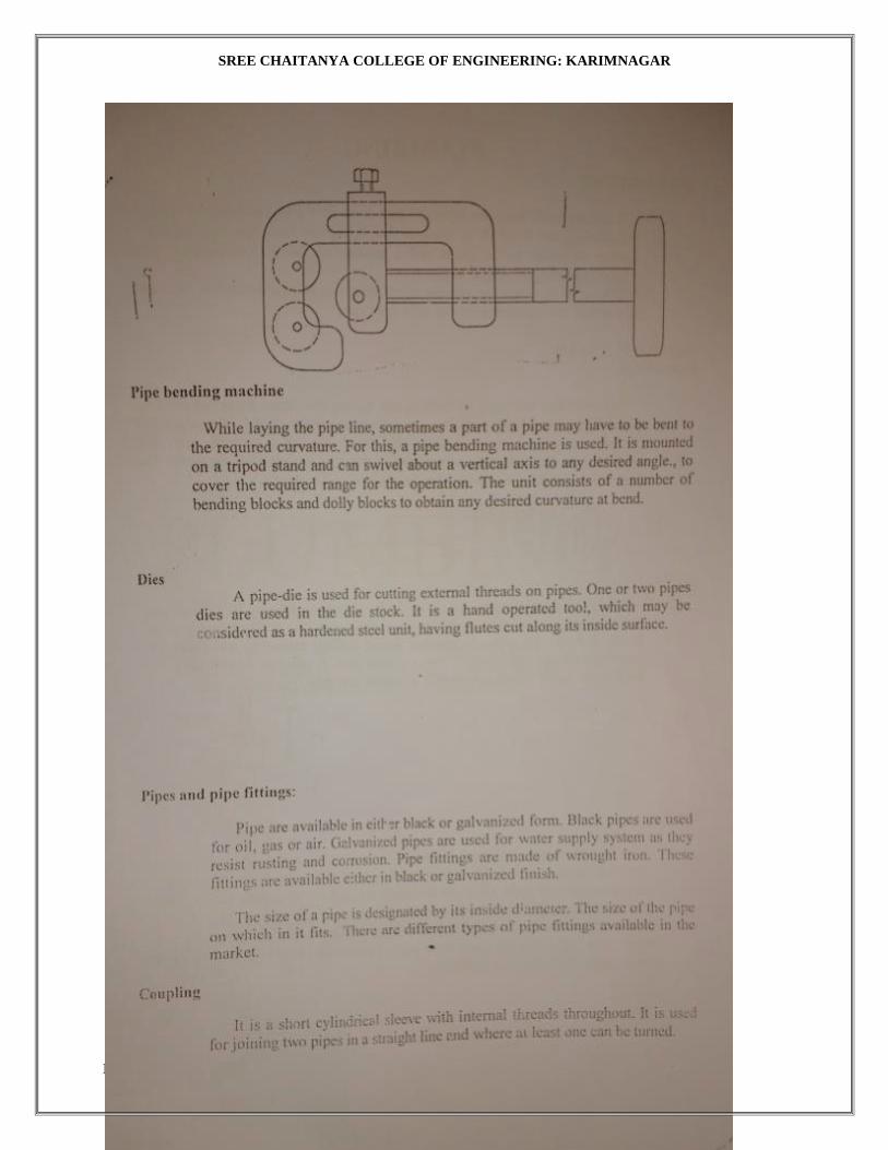
SREE CHAITANYA COLLEGE OF ENGINEERING: KARIMNAGAR
DEPARTMENT OF MECHANICAL ENGINEERING engineering workshop manual 66

SREE CHAITANYA COLLEGE OF ENGINEERING: KARIMNAGAR
DEPARTMENT OF MECHANICAL ENGINEERING engineering workshop manual 67
SREE CHAITANYA COLLEGE OF ENGINEERING: KARIMNAGAR
DEPARTMENT OF MECHANICAL ENGINEERING engineering workshop manual 68
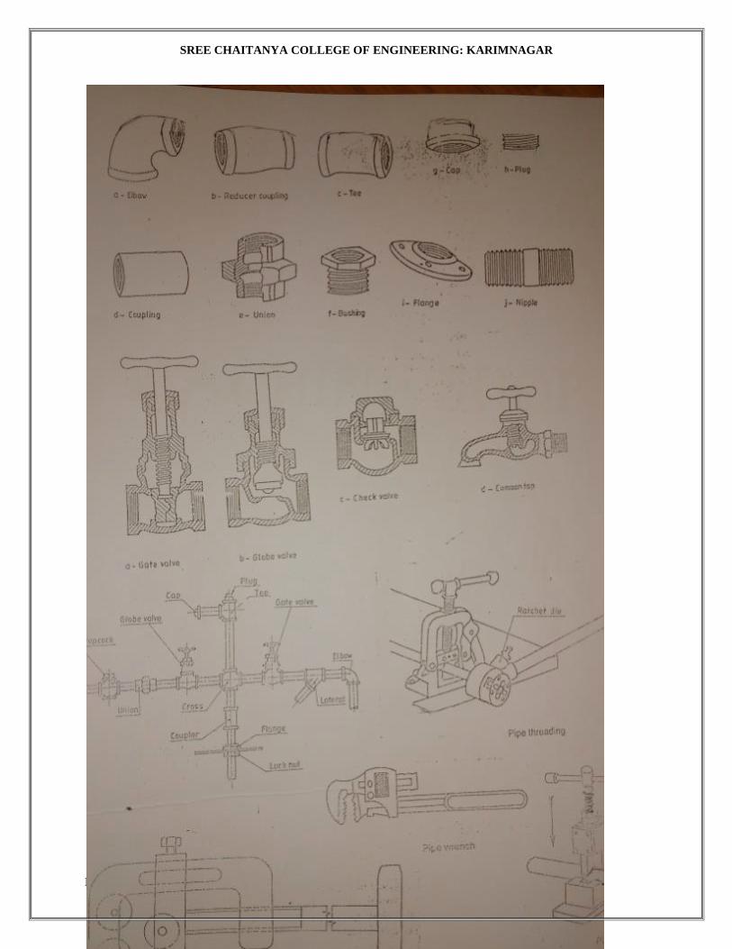
SREE CHAITANYA COLLEGE OF ENGINEERING: KARIMNAGAR
DEPARTMENT OF MECHANICAL ENGINEERING engineering workshop manual 69

SREE CHAITANYA COLLEGE OF ENGINEERING: KARIMNAGAR
DEPARTMENT OF MECHANICAL ENGINEERING engineering workshop manual 70