Embed Size (px)
Citation preview

CAROLINA SCIEN( 'ECHNOLOGY RESEARCH CENTERA UNIT OF THE DEPARTMENT OF NATURAL AND ECONOMIC RESOURCES
INDUSTRIAL NOISE CONTROL: Some Case Histories
Volume I
STR-504
RESEARCH TRIANGLE PARK, NORTH CAROLINA 27709

INDUSTRIAL NOISE CONTROL: SOME CASE HISTORIES VOL. I
Prepared by
Dr. Franklin D. HartDirector of the Center for Acoustical Studies
North Carolina State University
Mr. C. Leon NealNorth Carolina Science and Technology Research Center
Dr. F. O. Smetana, ProfessorDepartment of Mechanical & Aerospace Engineering
North Carolina State University
August 1974

TABLE OF CONTENTS
Page Number
Introduction
Corrugating Steel Stock 1
Quiet Stock Tube for Automatic Screw Machines 3
Ejector Chutes for Metallic Objects 5
Air Ejection Nozzles 8
Air Compressbf~rntake Pipe 10
Paper Shredder 12
Gasoline-Powered Golf Cart 15
Riveting Hammer 18
Vibratory Parts Feeder 21
Conveyor Line 23
Automatic Lathe 25
Wind Tunnel 27

INDUSTRIAL NOISE CONTROL: SOME CASE HISTORIES VOL. I
Introduction
What we know as "Noise" is always produced during manufacturing,processing, or materials handling operations; in fact, noise developsanytime a significant number of people congregate in one place. Suchnoise used to be regarded as a mark of economic well-being. Lately,however, a number of forces, which, individually, would not have beendecisive, have coalesced to demand amelioration of environmental noise.Among these are (1) an unprecedented general affluence, (2) a moreconcentrated, more mechanized population, (3) an understanding of themeans to reduce noise, and (4) demonstration of the causal relationshipbetween noise and hearing loss. These pressures led to the passage ofsweeping Federal legislation requiring that workers be protected fromnoise hazardous to their hearing, to community noise abatement rules, tolawsuits asking for injunctive relief from "noise pollution," and to increasedcustomer sensitivity to noise emanating from the products they buy. As aresult there is unprecedented interest in muting the sound of industrialprocesses and products.
Unfortunately, because the principles of noise control are not yetamong the working tools of most middle and upper level industrial super-visors, many inadequate noise remedies are purchased at highly inflatedprices. It would be unreasonable, however, to expect that most suchsupervisors would be able to take the time needed to become familiar withacoustic formalism from their regular duties. This collection of solutionsto industrial noise problems has therefore been assembled with the hopethat busy supervisors will be able to acquire a general sense of how suchproblems are analyzed and solved. Then from their personal knowledgeof hardware fabrication costs they should be able to arrive at an approxi-mate cost for solving similar or related problems in their own environments.
Each problem is described in relatively simple terms, with noisemeasurements where available. The solution is then given, often withexplanatory figures. Where the solution rationale is not so obvious anexplanatory paragraph is usually appended. As a preface to these solu-tions, a short exposition is provided below of some of the guiding conceptsused by noise control engineers in devising their solutions.
The concept for this publication originated with Dr. Franklin D. Hart,Director of the Center for Acoustical Studies at North Carolina StateUniversity, who prepared many of the solution descriptions presentedhere. Mr. C. Leon Neal of the NC/STRC staff prepared the remainder withthe exception of the wind tunnel discussion. Ms. Sylvia Sanders of the

NC/STRC technical staff prepared the sketches and graphs. Dr. F. O.S me tana contributed his solution to the wind tunnel noise problem andedited the entire report.
If a collection of this type proves popular, additional volumes will beprepared.
CONCEPTS IN NOISE CONTROL
In simplest terms there are three means by which noise can be pre-vented from inflicting hearing damage:
(1) The hearer can be provided with protective devices to keep thesound waves from entering the ear.
(2) The sound waves generated by a noise source can be absorbedor deflected prior to their reaching the ears of the hearer.
(3) The noise generating ability of the source can be reduced throughredesign.
The first means is generally the least expensive; the last means is themost expensive when applied to an existing situation. Unfortunately,insuring the proper wearing of protective devices by all affected em-ployees requires constant, intensive supervision because most suchdevices become uncomfortable to wear (after a while at least) and becausenoise-induced hearing loss is progressive and therefore not readily appar-ent to the hearer over short periods of time. For this reason redesign forlower noise output is usually a more satisfactory permanent solution.
What we perceive as noise is the arrival at our ears of a moderate-to-high amplitude fluctuation in the local air pressure. Plotted against time,this fluctuation is usually very irregular. To devise effective noise con-trols it is, of course, helpful to know as much of the nature of the noiseas possible. The more knowledge one has, the more avenues of attackone may use. One way to learn quite a bit is to measure these pressurefluctuations accurately and then attempt to represent them by a sum ofsimple waves, each having a unique frequency, amplitude, and phaserelationship. Isolating the dominant waves in a noise pattern through thismeans frequently enables one to identify the noise source in the machine;for example, one which occurs at a period corresponding with the rotationof a particular shaft or one which results from gear teeth striking an objectso many times per second.

There are devices on the market which employ narrow-pass-bandelectrical filters operating on the output of noise-sensing microphones todetermine the amount of acoustical energy present in narrow frequencybands of the noise. By scanning the entire audible range of frequenciesone can get quite a good picture of the constituent simple waves in thenoise. Even better results can be obtained by analyzing the noise signalmathematically using a digital computer.
Once the noise source is identified one can proceed to try to reduceits strength or at least absorb its output. The means by which one wouldabsorb acoustical radiation depend principally upon the frequency andintensity of the noise. Since the ear is most sensitive at frequencies around1000 Hz more attention must be given to this area although there can beproblems with high intensity radiation at ultrasonic frequencies as well asat sub-audible frequencies. In the latter case individuals become quitenauseated when exposed to such radiation because their internal organsare excited to resonance.
Acoustic energy can be likened to flowing water or electric current. Toattenuate an electric current one may use either resistive or reactive means.In water flow, a fine mesh screen represents a resistance, while a dia-phragm with one face in contact with the water and the other with a fixedvolume of gas might represent a reactance. The ability of a material to actas an acoustic damper must depend upon its physical size in relation to anacoustical wave length as well as to its natural lack of "springiness."Thus a given thickness of fiberglass will be more effective at dampinghigher frequencies than low. It is, in effect, a frequency-sensitive resis-tance.
Usually materials can absorb a given amount of acoustic energy perpound, the amount being dependent upon the material and the frequency.The damping capability is usually poorest at low frequencies so that forthese conditions heavy weights, commonly sheets of lead, layers of sand,or tar-like materials are required. This is one reason why luxury auto-mobiles are considerably heavier than their cheaper ( and noiser) coun-terparts which use the same basic body shell.
Reactive attenuation depends for its effectiveness on one's being ableto add a 180 out-of-phase component to a pressure wave. Inherently thismechanism limits the effectiveness of a single device to a narrow band offrequencies.
Reduction of noise source strength requires an understanding of theway noise is generated and a search for an alternate means of performing
in.
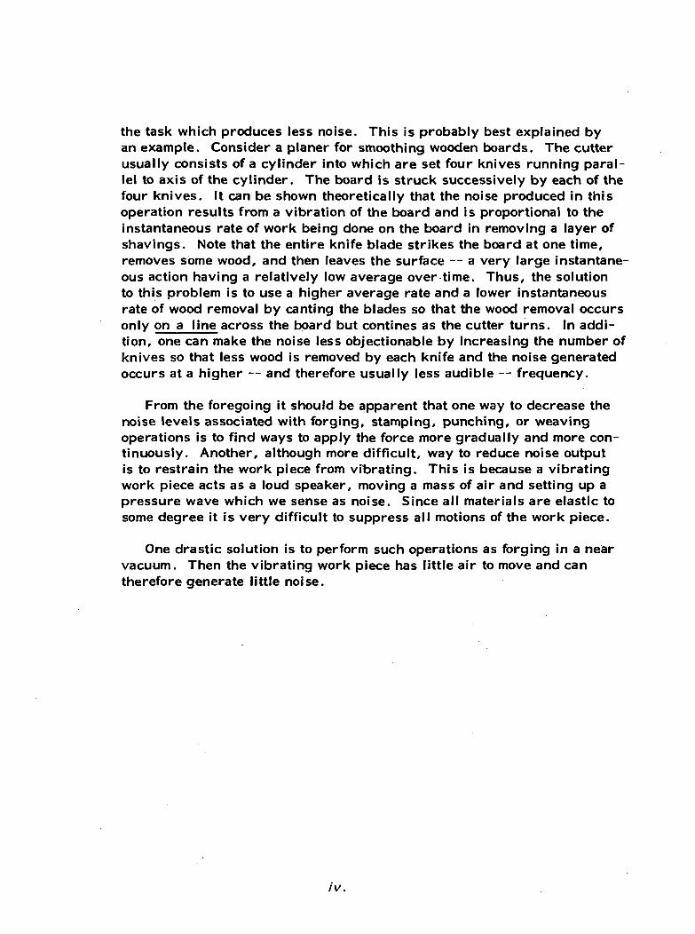
the task which produces less noise. This is probably best explained byan example. Consider a planer for smoothing wooden boards. The cutterusually consists of a cylinder into which are set four knives running paral-lel to axis of the cylinder. The board is struck successively by each of thefour knives. It can be shown theoretically that the noise produced in thisoperation results from a vibration of the board and is proportional to theinstantaneous rate of work being done on the board in removing a layer ofshavings. Note that the entire knife blade strikes the board at one time,removes some wood, and then leaves the surface — a very large instantane-ous action having a relatively low average over time. Thus, the solutionto this problem is to use a higher average rate and a lower instantaneousrate of wood removal by canting the blades so that the wood removal occursonly on a line across the board but confines as the cutter turns. In addi-tion, one can make the noise less objectionable by increasing the number ofknives so that less wood is removed by each knife and the noise generatedoccurs at a higher — and therefore usually less audible — frequency.
From the foregoing it should be apparent that one way to decrease thenoise levels associated with forging, stamping, punching, or weavingoperations is to find ways to apply the force more gradually and more con-tinuously. Another, although more difficult, way to reduce noise outputis to restrain the work piece from vibrating. This is because a vibratingwork piece acts as a loud speaker, moving a mass of air and setting up apressure wave which we sense as noise. Since all materials are elastic tosome degree it is very difficult to suppress all motions of the work piece.
One drastic solution is to perform such operations as forging in a nearvacuum. Then the vibrating work piece has little air to move and cantherefore generate little noise.
IV.

CORRUGATING STEEL STOCK
Problem Statement: Figures 1 and 2 illustrate anoperation for corrugating steel stock. The stockis fed through the corrugating rolls at speeds ofabout 80 ft/min. The action of the corrugatingrolls produced vibration in the sheet stock andsince the supply end was practically undamped,excessive sound radiation occurred. The noisalevel produced is shown in Figure 3.
PARTIAL ENCLOSURECROSS-SECTION
ACCESS MAT LFLOW
•IBER GLASSSHEET METAL
Figure 1. Partial Stock Enclosure for ReducingRadiated Sound
5PONGE RUBBER ROLL
SOFT RUBBER ROLLS
Figure 2. Corrugating Rollers
Problem Solution: Soft rubber rolls were placed on the in-feed sideto prevent vibration from propagation along the stock and resulting insound radiation. This procedure reduced the total effective surface

8OO
UJCt
2075
APPROXIMATE 8 HOURDAMAGE RISK
(1) 101 dB(A)
(2) 99 dB(A)
(3) 94 dB(A)
75 |50 300 600 I200 2400 4800106 300 600 1200 2400 4800 10,000
FREQUENCY-OCTAVE BANDS, Hz
Figure 3. Before and After Noise Levels
contributing to sound radiation. The effect on noise of the procedureis shown as curve (2) of Figure 3. A partial enclosure was used tosurround the roller assembly area which was then the area of greatestsound radiation. The partial enclosure provided additional reductionas illustrated by curve (3) of Figure 3.
Solution Source: This solution was presented by C. L. Coyne in theMarch, 1958 issue of NOISE CONTROL, p. 116.

QUIET STOCK TUBE FOR AUTOMATIC SCREW MACHINES
Problem Statement: In automatic screw machines, metal stock tubes areused to contain stock which is rotated at speeds of 4000 RPM and greater.When plain stock tubes are used, the vibration caused by inter-action ofthe stock with the stock tube resulted in excessive sound radiation. Noiselevels are affected by the size and shape of the stock and speed of rotation.One example is illustrated in Figure 4.
HELICALLY WOUND STEEL LINER
TEXTILE WEBBING
STEEL TUBE
Figure 4. Modified Stock Tube
Problem Solution: The solution is illustrated in the figure and repre-sents a modification of the plain stock tube. It is constructed of a he-lically wound inner liner, a fibrous filler (textile webbing) and theouter steel tube. The fibrous filler isolates the outer tube from theinner liner which is in contact with the rotating stock and absorbs vibra-tory energy from the inner liner before it is iadiated into acoustic energy.The liner, being helically wound, has better interaction with the fibrousmaterial which aids in attenuation.

APPROXIMATE 8 HOURDAMAGE RISK
LAIN STOCKTUBE (I)
MODIFIED STOCKTUBE (2)
37.5 75 150 300 600 1200 2400 480075 150 300 600 1200 2400 4800 9600
FREQUENCY — OCTAVE BAND, Hz
Figure 5. Noise Levels Produced by Plain andModified Stock Tubes
Solution Source: The solution presentation based on an article byB. J. Schweitzer in the March, 1956 issue of NOISE CONTROL, p. 14.The quiet stock tube illustrated was produced under patent in 1956by the Corlett-Turner Co., Chicago, Illinois.

EJECTOR CHUTES FOR METALLIC OBJECTS
Problem Statement: Smaller metallic parts are ejected onto the chuteas illustrated in Figure 6. The tumbling parts cause impact noise andinduce vibration of the metallic chute resulting in sound radiation.While the noise from such an arrangement conveying 30-caliber cart-ridge cases was not extremely high, the principles employed in itssolution apply equally well to situations wherein the noise levels pro-duced are more intense. ;
EJECTOR
EJECTOR CHUTE
NOISE RADIATION
CONTAINER
Figure 6. Ejector Chute

CHUTE CROSS-SECTION
20-gage galvanized steeKU-̂ -0.03311 cardboard
14-gage galvanized steel
Figure 7. Cross-Section of Treated Ejector Chute
Problem Solution: A sandwich was constructed using the original 14-gagesteel bottom of the chute, a middle layer of 0.035 in. thick cardboard, anda top plate of 20-gage galvanized steel. The fibrous cardboard providesdamping and vibration isolation with attendant noise reduction as noted by
APPROXIMATE 8 HOURDAMAGE RISK
IOOoqo*•UJcr
•o•»
o.
(I) 86 <JB(A)
^(2) 75 dB(A)
20 Z5_ 150 300 600 1200 2400 480075 150 3OO 6OO 1200 2400 4855 10̂ 00
FREQUENCY—OCTAVE BAND, Hz
Figure 8. Noise Levels of Ejector Chutes Beforeand After Treatment

comparing curves (1) and (2) in Figure 8 above. A sandwich construc-ted in this way can be held in place with several rigid connections with-out serious loss in efficiency. It is noted that the chute could be cappedwith an acoustically treated cover to provide additional noise reductionwhere required. In cases where the containers or tote boxes radiatenoise due to vibration of the objects, a treatment similar to that used forthe chute would be effective. For these applications, other fibrous fillermaterials such as felt or asbestos could also be used.
Solution Source: This presentation is based on an article by A. L.Cudworth in the January, 1959 issue of NOISE CONTROL, p. 40.

AIR EJECTION NOZZLES
Problem Statement: In many cleaning, drying, and ejection processes,high velocity air from small openings is employed and is a source ofintense noise. The nozzle (Figure 9) was used in a can drying processwhere it was important to have the air stream distributed over a relative-ly large area.
NOZZLEO.D. - 3/16 OPENING
3/16 " DIA.
5 HOLES1/16" DIA.
NOZZLE (2)
Figure 9. Air Ejection Nozzle
Problem Solution: Jet noise depends on jet diameter and exit jet streamvelocity with the sound energy concentrated at the higher frequenciesfor small, high velocity jets. The solution entailed replacing the highvelocity nozzle (1) with two lower velocity nozzles (2). The singlenozzle required higher velocity for the same area coverage. The noiseproduced from a flared fitting 1/4 inc. copper tube (3/16 in. nozzle dia-meter) is shown in Figure 10. The combination of smaller diameter
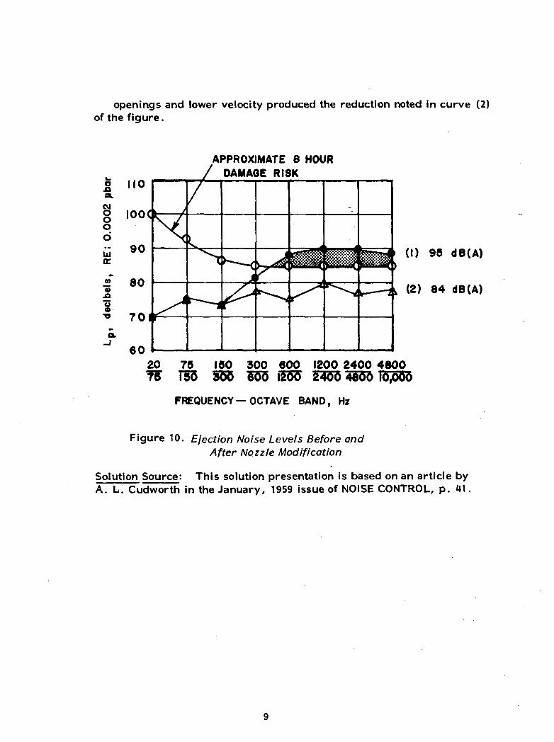
openings and lower velocity produced the reduction noted in curve (2)of the figure.
8oo
tuo:
0).o
s
20
APPROXIMATE 8 HOUR/ DAMAQE RISK
(1) 95 dB(A)
(2) 84 dB(A)
75 150 300 600 1200 2400 4800158 555 6155 iZ5o~ 14755 4io"o 10,000
FREQUENCY— OCTAVE BAND, Hz
Figure 10. Ejection Noise Levels Before andAfter Nozzle Modification
Solution Source: This solution presentation is based on an article byA. L. Cudworth in the January, 1959 issue of NOISE CONTROL, p. 41.

AIR COMPRESSOR INTAKE PIPE
Problem Statement: A 24 in. diameter, 49 ft. high air intake pipe for a9000-hp air compressor was protected from rain and other environmentalelements by an open-bottomed house (Figure 11). Sound was reflectedback to the ground and near the bottom edge of the enclosure an intensenoise spectrum was produced, see Figure 12.
PREVIOUS TREATMENT ON
ROOF ONLYFLOOR ADDED TO MAKE
AIR FLOW THROUGH DUCT
Figure 11. Silenced Air Compressor Intake Pipe
Problem Solution: As shown in the elevation view, a dissipative mufflerwas constructed by making an inner structure lined with 2 in. thick fiberglass. Intake air was forced to flow through the constructed duct by add-ing a floor which connects the inner wall with the intake pipe. Noise
10

§ 120.o
APPROXIMATE 8 HOUR/ DAMAGE RISK
(I) 114 dB(A)
(2) 95 dB(A)
20 757B~ 155
150 30O 600 1200 2400 4800655 1555 247ft
FREQUENCY-OCTAVE BANDS, Hz
Figure 12. Noise Levels Produced by Compressor IntakePipe Before and After Treatment
radiating from the pipe opening is attenuated by the turn and the linedduct as it propagates through the duct towards the ground. The degreeof attenuation is seen by comparing curves (1) and (2) in Figure 12.
Solution Source This solution presentation is based on an article byA. L. Cudworth in the January, 1959 issue of NOISE CONTROL, p. 43.
11

PAPER SHREDDER
Problem Statement: A device for shredding scrap cards and strip stockis illustrated in Figure 13. The shredding disk is 30 in. in diameter, andproduces a shearing cut frequency of 3600 RPM with four knife blades
) CEILINGACCUMULATOR
^
JFEED BELT SHREDDINGRIVES DISK
/ r--.1 r -i
C ) (•)| 1r §1
( ' '
\
")
BLOWER
3
-^
\
/ BACK/ WALL
^/ FLOOR
\ /
CONTAINER
fJ OPE
POS
FIBERGLASS-TUNNEL
<
RATOR- SITION
1 11
!_y— '-LINED
^- AC
i
SIDE WALL
DED
.
WALL BACK
WALL
SIDE WALL
Figure 13. Acoustically Treated Paper Shredder
12

equally spaced on the disk. Material is fed to the shredding disk by topand bottom endless belt drives and the shredded paper is fed into a con-tainer . While the absolute values of noise levels is not given in the spec-trum, exposure at the operator's position was considered to be excessive.
Problem Solution: Since the shredding machine was already enclosed onthree sides by concrete, brick, and glass walls, a fourth wall was addedto form an enclosure. The added wall was constructed using the doublewall procedure and consisted of staggered 2" x 4" studding on 2" x 6"face and header plates and covered with 3/8 in. gypsum wall board. A1/4 in. double glass viewing window was placed in the wall directly abovethe infeed drive unit. An access door, 44 in. wide by 7 ft. high, wascovered on both sides with 3/8 in. gypsum wall board (for additionalnoise attenuation) and provided with sponge rubber gasket seals at the topand on each side. The infeed belt drive assembly protruded through thewall and was capped by a 1 ft. long tunnel lined with acoustical absorbingmaterial to provide attenuation for noise escaping through the access hole.
BOTH MEASUREMENTS AT O P E R A T O R ' S POSITION
( I )
(2 )
20TB~
75 150 300 600 1200 2400 4800150 300 600 1200 2400 4800 10.000
Frequency - Octave Bands, Hz
Figure 14. Paper Shredder Noise Levels Before andAfter Treatment
13

Fiberglass panels were placed on the inside walls of the enclosure withadditional panels suspended from the ceiling to prevent reverberationbuild up inside the room. The overall attenuation achieved by the enclo-sure measured at the operator's position is shown in Figure 14.
Solution Source: This solution presentation is based on an article byJohn R. Engstrom appearing in the March, 1956 issue of NOISE CONTROL,p. 20.
14

GASOLINE-POWERED GOLF CART
Problem Statement: A manufacturer of gasoline-powered golf carts hadan acoustically untreated model which produced a noise level of 98dbawith a peak of 100 db at 250 hertz at the rider's ear level. By use ofimproved engine isolation mounts, a new muffler design, flexible rubberair intake, and some fiberglass treatment of the body a level of 84 dbawith a peak of 86 db at 250 hertz at the rider's ear was achieved (98 db -250 Hz at ground level at rear wheels). The prime competitor of thismanufacturer had a model which produced only 80 dba at ear level and thefirm's distributors and dealers advised them that they could not writeorders for new model carts unless they were below the 80 dba noise levelat the rider's ear level.
Problem Solution: Because the floor of the cart must be left open forcooling, it was necessary to use a type of acoustic reflecting and absorb-ing material. Representatives of Consolidated Kinetics aided in the solu-tion and all products used were Ferro Cousti-Products.
The acoustical treatment developed involved:
1. Replacement of fiberglass insulation on engine box (front and sides)and the bottom of the seat cushion with Ferro Cousti-Composite 10-100held by 1/2" foam bonded to the surface as shown in figure 15.
METAL OR PLYWOOD SURFACETO BE TREATED
1/2 COUSTIFOAM
COUSTIFILM (OR
I" COUSTIFOAM
Figure 15. Acoustical Treatment for Engine Compartment
15

2. Treatment of rear fenders, front of gas tank, and forward sideof golf bag rack panel with 1" coustifoam.
The total cost of the material used for treatment was $39.00 and thenoise level was reduced to 75 dba at ear level (86 dba at ground level/rear wheel). This was an overall reduction of approximately 11 dbaand placed the cart in a favorable position relative to the chief competingbrand.
Pictures of the treated engine compartment and seat cushion follow.
\
INSIDE ENGINE COMPARTMENTShowing Cousti-Composite 10-100 on side and front of engine compartment.Coustifoam on fender.
16

SEAT CUSHIONCousti-Composite 10-100 adhered to underside.
Applications: Similar principles can be applied to lawn mowers,snow-mobiles, factory vehicles, etc. which have small gasoline engines.
Solution Source: Company literature Ferro Corporation, Eastern Com-posites Division, Norwalk, Connecticut.
17

RIVETING HAMMER
Problem Statement: Rivetinghammers are a common sourceof excessive noise exposure.The type presented here (Fig. 16)has a continuously running motorwith a hammer, eccentricallydriven, that is actuated by a foot-operated clutch lever. Its opera-ting frequency varies between afew hundred and 3000 blows perminute. The figures illustratethe relative noise spectrum andthe treatment provided. Thespectrum levels presented (Fig.18) are the maximum values re-corded for each octave band.
ECCENTRIC AND DRIVE MOTOR
HAMMER
ANVIL
CONTROL
FOOT CLUTCH
Figure 16. Riveting Hammer
Problem Solution: A partial enclosure with absorbing material inside,fitted around the motor and impact area is illustrated in Figure 17. Itis, in effect, a box with a plexiglass front cover leaving the minimumgap required for access to the anvil area. Since the ear level is abovethe gap area, no direct path exists between the noise source (impactarea) and the ear. All interior surfaces are lined with absorbing ma-terial and covered with perforated metal. The enclosure has indepen-dent support and is not attached directly to the riveting machine. Thenoise reduction provided by an enclosure of the type illustrated isshown in the spectrum figure.
18

1. Removable section for adjusting anvil - 1/2" plywood, soundabsorbing felt, perforated metal covering - 4600 holes per sq. ft.,0.068 in. dia.
2. Plywood, sound absorbing felt, perforated metal covering.
3. Plywood, fiberglass, perforated metal covering.
4. Metal shield.
5. Plexiglass shield to reflect sound back into absorbing interior andprovide good vision. It is attached to front so that it can be adjusted invertical direction.
6. Top cover is hinged so top can be lifted up to provide access to motorand drive assembly for maintenance, adjustments, etc.
7. Support structure for partial enclosure around motor, hammer, andanvil area.
Figure 17. Sound-Absorbing Enclosure
19

BOTH MEASUREMENTS AT OPERATOR'S POSITION
0
40
30
20
BEFORE
AFTER
(I)
(2)
2075
75
50
150
300
300
600
6001200
1200 2400 46002400 4800 10,000
Frequency - O c t a v e Bands, Hz
Figure 18. Before and After Acoustical Treatment NoiseSpectra for Riveting Hammer
Solution Source: The presentation is based on an article by JohnR. Engstrom in the March, 1956 issue of NOISE CONTROL, p. 18.The description of the enclosure has been modified to provide moredetail.
20

VIBRATORY PARTS FEEDER
Problem Statement: A common noise source in manufacturing plants isa vibratory parts feeder. This device is a large metal bowl mounted ona vibrating base. Randomly oriented parts are placed in the bowl andthe vibrations cause the paths to follow a prescribed path. The path issuch that only correctly oriented parts can exit from the bowl.
1/4" LD-400outside Bowl
Sprayed Urethaneinside Bowl
Figure 19. Acoustical Treatment of Bowl
The noise of this machine comes from the bowl, the parts impacting thebowl, and the parts impacting each other. The noise of the bowl itselfis usually a small portion of the overall noise except in the case of afabricated steel bowl. For a fabricated steel bowl the substitution of abowl of different material may have a large noise reduction effect.
The particular problem cited below involved a 30-inch diameter alumi-num bowl.
Problem Solution: The method used to reduce the noise of this vibratoryfeeder involved:
(1) Polyurethane coating on the inside of the bowl (See Figure 19);
21

(2) Damping material (1/4 inch LD-400) on the outside of the bowl;
(3) Acoustically treated hood over the bowl.
The total reduction using these three treatments was 8 dba (Figure 20) .
Solution Source: Glenn E. Warnaka, H. T. Miller and J. M. Zalos,"Structural Damping as a Technique for Industrial Noise Control,"American Industrial Hygiene Association Journal, January, 1972, p. 1-11.
xOcvJ
0)
-I CM0- £V) o
•o wc »0 £.CD >>
oO
ro
31.5 63 125 250 500 1000 2K 4K 8K I6KFrequency In Hz
• No Acoustical Treatment
[100 dB(A), 104 dB(L)]
• Damping on Bowl , Hood over Bowl[92 dB(A) , 94.5 dB(L)]
Figure 20. Noise Spectra of Bowl Before and AfterAcoustical Treatment
22

CONVEYOR LINE
Problem Statement: The problem involved a conveyor line which removedmetal parts from a large industrial dryer. The exit chute was constructedof heavy gauge steel and the material leaving the dryer was ejected at highvelocity. The impact of the ejected parts against the chute produced a highnoise level. Operating personnel are not continuously in the area; however,servicemen working on machines are often in the area.
Problem Solution: The solution to this problem involved the application ofdamping material to the outside of the chute. The material selected wasLD 400 damping material manufactured by Lord Manufacturing Company.The thickness used was 0.125". (Figure 21)
I/8 LD 400
I/8 LD 400
Figure 21. Acoustical Treatment of chute
As seen in Figure 22, the reduction was 5 to 6 db in all frequencies bands.This reduced the noise level sufficiently for the workmen to service themachines within permissible noise exposure limits.
Solution Source: Glenn E. Warnaka, H. T. Miller, and J. M. Falos,"Structural Damping as a Technique for Industrial Noise Control,"American Industrial Hygiene Association Journal, January, 1972, p. 1-11.
23

V O
-J :1>
*a O
Ql 9CJ
T3
J 8
I 10
100
31.5 63 125 250 500 1000 2K 4K 8K I6K
Frequency in Hz
Figure 22. A/o/'se Specfro of C/7t/fe Before and AfterAcoustical Treatment
24

AUTOMATIC LATHE
Problem Statement: In a facility with bar automatic lathes the noise isfrequently in the range of 96-110 dba. The lathes may be single spindlemachines; however, they are often multi-spindle (6) machines. The
SPRING.
LOCATING BUSH.
THIN WALLED BUSH. METAL BUSHFOR LOCATIONOF NYLON TUBE
LOCKING PIN.
Figure 23. Stock Tube with Acoustical Liner
oX
<M
CD-Q
o>>0>
01
3in
3OV)
110
100
90
80
70
IOQ
90
80
70
60
• Machine(a)
Machine- (b)
Untreated
Untreated
512 5 IK 2K 5K IOK 20K ABCLin
Frequency, Hz
Figure 2H. Effect of Stock Tube Lining on Machine Noise
25

noise observed in a lathe factory is typically a general noise with asuperimposed characteristic noise produced by the rattling of stockbars against the feed guide tubes. This noise is especially noticeablewhen hexagonal bars are rotated at high spindle speeds. In the paperupon which this example is based, a solution is sought to the noise pro-duced by the bar stock in the feed guide tubes.
Problem Solution: The solution was to machine and fit nylon tubes in-side each of the steel stock tubes as shown in Figure 23.
In addition, a lightly spring-loaded canvas strap was fitted around theset of tubes to prevent the tubes themselves from generating noise. Be-fore and after noise measurements are given (Figure 24) for two differentmachines. The two examples show that the machines differ due to ageand condition; however, the treatment was effective for each machine.
The overall reduction for machine A was 25 dba and for machine B, itwas about 15 dba.
Solution Source: G. L. Lee and D. J. Smith, "The Control of NoiseProduced by Bar Automatic Lathes," Annuals Occupational Hygiene,Vol. 14, pp. 337-343, 1971.
26

WIND TUNNEL
Problem Statement: Two large Roots pumps (size 2060) are used topower an induction wind tunnel (Figure 25) . Each is turned at 360 RPMby a 150 HP electric motor. Total air flow rate into the pumps in thisconfiguration is 17,500 cfm. Minimum permissible pump suction pres-sure is 10.7 psia and maximum discharge pressure is approximately at-mospheric. The pumps (weight about 15,000 Ibs. each) are bolteddirectly to an 8" concrete floor. The wind tunnel inlet and dischargeline consist largely of 1/8" thick wall steel pipe up to 30" diameter andare bolted directly to the pumps. These lines are suspended by straphangers from the building structure, either floor or ceiling. The noisefrom the operation of this wind tunnel made attending personnel ill afteronly a few minutes exposure, shook the entire academic building in whichit was located, and in general made other activity in the building and itsenvirons impossible. The measured noise spectrum in the vicinity ofthe tunnel exhaust exceeded 120 db with the intensity highest at thelowest measured frequency. Indications are that it reached a maximumat about 12 Hz.
Restrictions on Solutions: Mufflers that restrict the air flow significantlycannot be used because the pressure limits of the Roots pumps will thenbe exceeded. Cost of sound controls have to be absorbed by a researchproject which is not budgeted for this purpose. Plumbing on the suctionside of the pumps must be vacuum tight for satisfactory tunnel operation.Suction side plumbing for the most part cannot be lined internally becauseof the deleterious effect on flow quality.
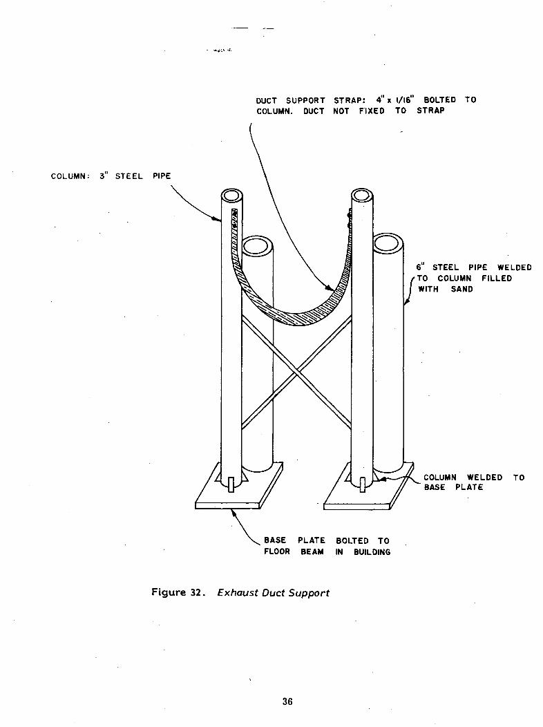
Problem Solution: The solution to the noise problem was arrived atprogressively through a series of treatments. The first item applied tothe system is shown in Figure 29. This was effective at the lowest fre-quencies as had been expected. The device shown in Figure 30 wasthen added with moderate success. This was followed by that shown inFigure 28. A small additional reduction in noise level was obtained.Finally, satisfactory exhaust line quieting was achieved through the ad-dition of the device shown in Figure 31. Suspension of the exhaust ductfrom the building floor was accomplished as shown in Figure 32.
Inlet side quieting was achieved by the treatments depicted in Figures26 and 27.
27

Solution Rationale: A Roots pump consists of two tightly-fitting figure-eight lobes geared together with the major axes of the lobes at 90° toone another. Every revolution of the shaft results in the application oftwo sharp pressure pulses to the air flow in the exhaust duct. With thepumps running at 360 RPM (6 RPS) there is applied to the steady stateflow a rather distorted sine wave modulation having a fundamental fre-quency of about 12 Hz. Energy at this frequency is very difficult to atten-uate by dissipative means. Another way of saying this is that it requiresa large amount of damping material such as fiberglass, lead, mastic, etc.to absorb significant energy at these frequencies. Further, the use ofthese materials in sufficient quantities to be effective will result in exces-sive pressure drops in the system. Reactive attenuators have the disad-vantage that they operate only over a narrow band of frequencies. Unfor-tunately , square waves such as those produced by Roots pumps have alarge harmonic content so that a side branch resonator tuned to 12 Hz. willattenuate only the fundamental tone in the exhaust flow. But since reactiveattenuators cause little or no pressure drop one has little choice but touse them for the attenuation of low frequency noise in this application.
Two such attenuators were constructed and installed and the noise spec-trum measured. Significant improvement was noted. The spectrumindicated other likely frequencies below 400 Hz where this type of attenua-tion might be effective, the most prominent being at 250 Hz. An additionalresonator tuned for this frequency was added but the benefit was notvery large.
The higher frequency noise which was more "white" in nature seemed torequire dissipative mufflers to attenuate it adequately. Accordingly, firstthe smaller in-line dissipative muffler and then the larger one were in-stalled. These, in conjunction with the cones installed to inhibit thedevelopment of standing waves in the exhaust duct, and the use of canvasisolators in a section of duct brought the exhaust noise level to within thedesired range.
The treatment of the inlet plumbing is quite conventional: wrapping ofthe duct externally with absorbent materials to attenuate noise and preventradiation from the duct. In the low speed areas of the inlet duct, theacoustical treatment is applied internally.
Solution Source: Department of Mechanical and Aerospace Engineering,North Carolina State University, Raleigh, North Carolina 27607
28

EXHAUST
side branchresonator
upstream end ofexhaust duct
inline muffler
test section
diffuser
pumps
Figure 25. Layout of Tunnel Components
29

PLENUM CHAMBER TREATED INSIDEWITH ASPHALTIC ROOFING CEMENTAND 2" FIBERGLASS — SCREENS,WITH FIBERGLASS BETWEEN, OVERINLET
TEST SECTION
REMAINDER OF INLET ANDTEST SECTIONS UNTREATED
Figure 26. Tunnel Inlet Section
30

EXTERIOR COATED WITH ASPHALTICROOFING CEMENT, FIBERGLASS, ANDWRAPPED WITH MUSLIN SHEETING
Figure 27. Wind Tunnel Diffuser
31

ISOLATOR SECTIONSUPPORT
250 Hz SIDE BRANCHRESONATOR
6" CANVAS COUPLING
-30" DUCT, 1/8" WALLSTEEL
INTERNAL TURNING VANESIN CORNER
Figure 28. Exhaust Duct:Upstream End
FLOW FROMROOTS BLOWER
32

16" PIPE CONNECTOR
WELDEDI-BEAM
66"
Inside of resonator coated with1/2" asphaltic roofing cement towhich Is applied a 2" layer offiberglass
RESONATOR(Volume = 129 ft )
30 EXHAUST DUCT(1/8" wall)
AIR FLOWDIRECTION
Figure 29. 12 Hz Side Branch Resonators
33

SHELL 60" Did.
INTERIOR FITTED SAMEAS OTHER DEVICES
Figure 30. Inline Resonator
34

D1FFUSER - STEEL FRAMEWORKFIBERGLASS BETWEEN STEEL FRAMESCOVERED BY HARDWARE CLOTH 30" x 1/8" wall
EXHAUST DUCT
TWO ADDITIONAL LOCATED INEXHAUST DUCT- ONE UPSTREAMOF MUFFLER, ONE DOWNSTREAM
1/8" thick steel- MUFFLER SHELL
72" O.D. x 72" LONG
INTERIOR COATED WITH1/2" ASPHALTIC ROOFINGCEMENT TO WHICH ISSTUCK 4" OF FIBER-GLASS— HELD IN PLACEBY HARDWARE CLOTH
3/4" PLYWOOD
€A/ FLOW
Figure 31. Inline Muffler
35
COLUMN: 3 STEEL PIPE
DUCT SUPPORT STRAP: 4"x i/ie" BOLTED TOCOLUMN. DUCT NOT FIXED TO STRAP
6 STEEL PIPE WELDEDTO COLUMN FILLEDWITH SAND
COLUMN WELDED TOBASE PLATE
BASE PLATE BOLTED TOFLOOR BEAM IN BUILDING
Figure 32. Exhaust Duct Support
36