Embed Size (px)
Citation preview
CAROLINA POWER & LIGHT COMPANY
ROBINSON NUCLEAR POWER PLANT
UNIT 2
EDDY CURRENT EXAMINATION REPORT
APRIL 1992
DOCUMENT NO. IR-ISI-136
ASEA BROWN BOVERI COMBUSTION ENGINEERING, INC.
NUCLEAR POWER BUSINESSES OUTAGE SERVICES
PREPARED BY: DATE
APPROVED BY: 6 EVEL III DATE
APPROVED BY:
.A. ENGINEER DATE
APPROVED BY: 6 ?4'L AGER NDE SERVICES DATE
9209290245 920921 PDR ADOCK 05000261 G PDR
Document No: IR-ISI-136
ABSTRACT
This document summarizes the examination program, results, and presents information concerning examination procedures, personnel and equipment used for inspection at the H.B. Robinson Unit 2 1992 outage.
The eddy current examination outage included eddy current inspections utilizing the Zetec bobbin probes for defect examination. One MRPC examination was performed in the cold side 5th support area to further evaluate a suspect indication. A 20% fulllength bobbin probe examination was performed in steam generator's 1, 2 and 3, except for row 1 tubes which were examined from 6C to HTE. One tube was plugged in steam generator "A", (Row 1 Column 29). This tube was obstructed to a. .580" probe at the 6th hot leg support. Details are contained in the text of this document.
Document No: IR-ISI-136
TO: Carolina Power & Light Co.
CERTIFICATE OF PERFORMANCE
Carolina Power & Light Co. H.B. Robinson Plant, Unit 2
Steam Generator Eddy Current Examination
Combustion Engineering, Inc., hereby certifies that the Robinson Unit 2 steam generator eddy current examinations performed during April 1992 were in compliance with CP&L Purchase Order XM 10370000/WA# XS 10370002. Documentation attesting to this conformance is contained within the data of this QC Records Package.
Q. A. Engineer
Document No: IR-ISI-136
TABLE OF CONTENTS
TITLE PAGE
CERTIFICATE OF PERFORMANCE
ABSTRACT
TABLE OF CONTENTS
VOLUME I
SECTION I
GENERAL INFORMATION
Tab 1 Introduction
2 Examination Summary and Results
Work Scope Summary
Inspection Summary
A S/G #1 Graphic Displays B S/G #2 Graphic Displays C S/G #3 Graphic Displays
3 Acquisition Test Parameters
4 Scan Plan & revisions
Document No: IR-ISI-136
VOLUME I
SECTION II
PROCEDURES
Tab 1 ROB-410-004 Rev. 4 [SP-1110 Rev. 0] - Eddy Current Examination of
Nonferromagnetic Steam Generator Tubing Using MIZ-18 Equipment.
2 ROB-410-005 Rev. 3 [SP-1111 Rev. 0] - Eddy Current Data Analysis Procedure Evaluation of Westinghouse Steam Generator Tubing. Analysis Guideline, Change forms and acknowledgements.
3 STD-410-076 Rev. 0 [SP-1112 Rev. 0] - Control of S/G Eddy Current Examination Data Using The Personal Computer (PC) Data Base System.
4 STD-410-075 Rev. 01 [SP-1113 Rev. 01 - Remote Installation, Calibration, and Removal of SM-10/20 Manipulator.
5 ROB-410-008 Rev. 1 [SP-1114 Rev. 01 - Procedure for the Installation and Removal of Temporary Nozzle Covers.
SECTION III
PERSONNEL
Tab 1 QAP-2.4 Rev. 1 - Combustion Engineering Certification Program for
Nondestructive Examination Personnel.
2 Personnel certification documents.
SECTION IV
EQUIPMENT
Tab 1 Equipment (RDAU) Certification Records
Calibration Standard Certification Records
Document No: IR-ISI-136
VOLUME II
STEAM GENERATOR #A EXAMINATION DATA
Tab 1 Data package transmittal and CP&L receipt acknowledgement.
2 All Data on all Tubes sorted in Row - Column order.
3 All Tubes selected by CP&L as Previous Indication tubes with supportive data from 1990, 1988 and 1977 outages.
4 Final DDA-4 Report Printouts and Lissajous Printouts for all Data sorted by reel number.
5 Eddy Current Calibration Sheets.
STEAM GENERATOR #B EXAMINATION DATA
Tab 1 Data package transmittal and CP&L receipt acknowledgement.
2 All Data on all Tubes sorted in Row - Column order.
3 All Tubes selected by CP&L as Previous Indication tubes with supportive data from 1990, 1988 and 1977 outages.
4 Final DDA-4 Report Printouts and Lissajous Printouts for all Data sorted by reel number.
5 Eddy Current Calibration Sheets.
Document No: IR-ISI-136
STEAM GENERATOR #C EXAMINATION DATA
Tab 1 Data package transmittal and CP&L receipt acknowledgement.
2 All Data on all Tubes sorted in Row - Column order.
3 All Tubes selected by CP&L as Previous Indication tubes with supportive data from 1990, 1988 and 1977 outages.
4 Final DDA-4 Report Printouts and Lissajous Printouts for all Data sorted by reel number.
5 Eddy Current Calibration Sheets.
Document No: IR-ISI-136
INTRODUCTION
Combustion Engineering, Inc. conducted an in-service eddy current examination of the steam generator (S/G) tubing at Carolina Power & Light (CP&L) Robinson Unit 2 Nuclear Power Plant in April 1992. The purpose of the examination was to assess the condition of the S/G's, identify tubes requiring repair and to provide the necessary information needed to fulfill Technical Specification requirements.
The examination program included multi-frequency bobbin coil and motorized rotating pancake coil (MRPC) testing for indications of degradation, dents, and deposits.
The examinations were conducted in accordance with Combustion Engineering Procedure No. ROB-410-004 Rev. 4 in compliance with the USNRC Regulatory Guide 1.83 "Inservice Inspection of PWR Steam Generator Tubes", Revision 1, dated July, 1975 and the ASME Boiler and Pressure Vessel Code, Section Xl "Rules for Inservice Inspection of Nuclear Power Plant Components", 1986 Edition, with no Addenda, and the Robinson Unit 2 Technical Specifications.
The eddy current data analysis variables were established in accordance with the * Procedure No. ROB-410-005 Rev. 3 "Eddy Current Data Analysis Procedure, Evaluation
of Westinghouse Steam Generator Tubing", and the attached Guideline, H.B. Robinson Eddy Current Analysis Supplement. The data was independently analyzed by two groups of certified Level IIA (minimum) data analysts. Discrepancies between the two sets of evaluation results were reviewed by a Lead Level III eddy current examiner.
Document No: IR-ISI-136
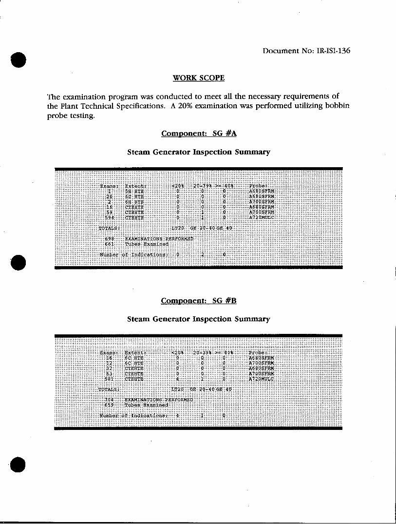
WORK SCOPE
The examination program was conducted to meet all the necessary requirements of the Plant Technical Specifications. A 20% examination was performed utilizing bobbin probe testing.
Component: SG #A
Steam Generator Inspection Summary
Exams: Extent: <20% 20-39% >= 40% Probe: 1 55 BTE 0 0 0 A680SFRM 26 6C HTE 0 0 0 A680SFRM 2 6H HTE 0 0 0 A700SFRM 16 CTEHTE 0 0 0 A680SFRM 59 CTEHTE 0 1 0 A700SFRM 594 CTEBTS 0 1 0 A720MULC
TOTALS: LT20 GE 20-40 GE 40
698 EXAMINATIONS PERFORMED 661 Tubes Examined
Number of Indications: 0 2 0
Component: SG #B
Steam Generator Inspection Summary
Exams: Extent: <20% 20-39% >= 40% Probe: 16 6C HTE 0 0 0 A680SFRM 12 6C HTE 0 0 0 A700SFRM 32 CTEHTE 0 0 0 A680SFRM 63 CTEHTE 0 0 0 A700SFRM 581 CTEBTE 4 1 0 A720MULC
TOTALS: LT20 GE 20-40 GE 40
704 BRAMINATIONS PERFORMED
659 Tubes Examined
Numiber of Indicqations: 410
(III
Ce Document No: IR-ISI-136
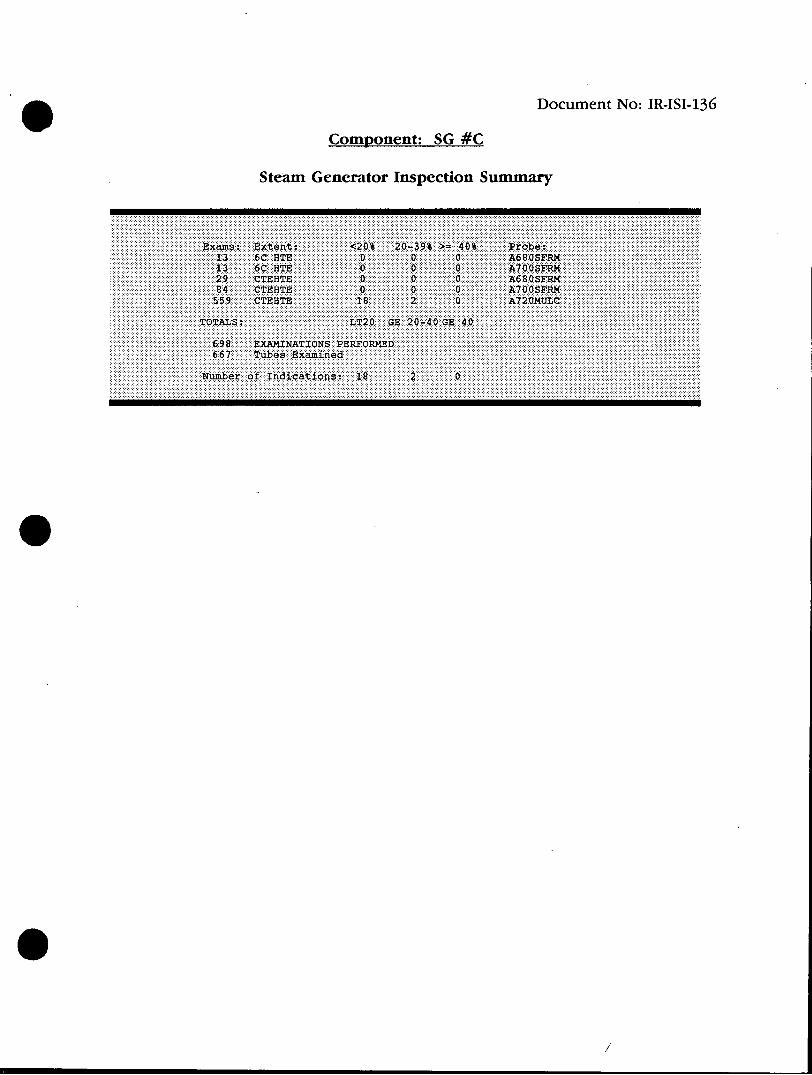
Component: SG #C
Steam Generator Inspection Summary
Exams: Extent: <20% 20-39% >= 40% Probe: 13 6C HTE 0 0 0 A680SFRM 13 6C HTE 0 0 0 A700SFRM 29 CTEHTE 0 0 0 A680SFRM 84 CTEHTE 0 0 0 A700SFRM 559 CTEHTE 18 2 0 A720MULC
TOTALS: LT20 GE 20-40 GE 40
698 EXAMINATIONS PERFORMED 667 Tubes Examined
Number of Indications: 18 2 0
0II
Summary Document No: IR-ISI-136
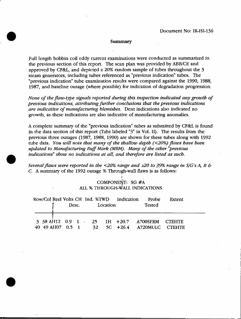
Full length bobbin coil eddy current examinations were conducted as summarized in the previous section of this report. The scan plan was provided by ABB/CE and approved by CP&L, and depicted a 20% random sample of tubes throughout the 3 steam generators, including tubes referenced as "previous indication" tubes. The "previous indication" tube examination results were compared against the 1990, 1988, 1987, and baseline outage (where possible) for indication of degradation progression.
None of the flaw-type signals reported during this inspection indicated any growth of previous indications, attributing further conclusions that the previous indications are indicative of manufacturing blemishes. Dent indications also indicated no growth, as these indications are also indicative of manufacturing anomalies.
A complete summary of the "previous indication" tubes as submitted by CP&L is found in the data section of this report (Tabs labeled "3" in Vol. II). The results from the previous three outages (1987, 1988, 1990) are shown for these tubes along with 1992 tube data. You will note that many of the shallow depth (<20%) flaws have been updated to Manufacturing Buff Mark (MBM). Many of the other "previous indications" show no indications at all, and therefore are listed as such.
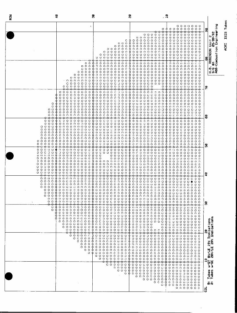
Several flaws were reported in the <20% range and 20 to 39% range in SIG's A, B & C. A summary of the 1992 outage % Through-wall flaws is as follows:
COMPONEN T: SG #A ALL % THROUGH-WALL INDICATIONS
Row/Col Reel Volts CH Ind. %TWD Indication Probe Extent Desc. Location Tested
3 38 AH12 0.9 1 . 25 1H +20.7 A700SFRM CTEHTE 40 49 AHO7 0.5 1 32 5C +26.4 A720MULC CTEHTE
Document No: IR-ISI-136
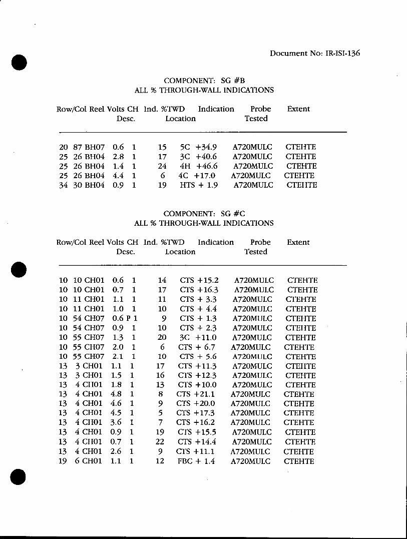
COMPONENT: SG #B ALL % THROUGH-WALL INDICATIONS
Row/Col Reel Volts CH Ind. %TWD Indication Probe Extent Desc. Location Tested
20 87 BHO7 0.6 1 15 5C +34.9 A720MULC CTEHTE 25 26 BHO4 2.8 1 17 3C +40.6 A720MULC CTEHTE 25 26 BHO4 1.4 1 24 4H +46.6 A720MULC CTEHTE 25 26 BHO4 4.4 1 6 4C + 17.0 A720MULC CTEHTE 34 30 BHO4 0.9 1 19 HTS + 1.9 A720MULC CTEHTE
COMPONENT: SG #C ALL % THROUGH-WALL INDICATIONS
Row/Col Reel Volts CH Ind. %TWD Indication Probe Extent Desc. Location Tested
10 10 CHO1 0.6 1 14 CTS + 15.2 A720MULC CTEHTE 10 10 CHO1 0.7 1 17 CTS + 16.3 A720MULC CTEHTE 10 11 CHO1 1.1 1 11 CTS + 3.3 A720MULC CTEHTE 10 11 CHO1 1.0 1 10 CTS + 4.4 A720MULC CTEHTE 10 54 CHO7 0.6 P 1 9 CTS + 1.3 A720MULC CTEHTE 10 54 CHO7 0.9 1 10 CTS + 2.3 A720MULC CTEHTE 10 55 CHO7 1.3 1 20 3C +11.0 A720MULC CTEHTE 10 55 CHO7 2.0 1 6 CTS + 6.7 A720MULC CTEHTE 10 55 CHO7 2.1 1 10 CTS + 5.6 A720MULC CTEHTE 13 3 CHO1 1.1 1 17 CTS +11.3 A720MULC CTEHTE 13 3 CHO1 1.5 1 16 CTS + 12.3 A720MULC CTEHTE 13 4 CHO1 1.8 1 13 CTS + 10.0 A720MULC CTEHTE 13 4 CHO1 4.8 1 8 CTS +21.1 A720MULC CTEHTE 13 4 CHO1 4.6 1 9 CTS +20.0 A720MULC CTEHTE 13 4 CHO1 4.5 1 5 CTS + 17.3 A720MULC CTEHTE 13 4 CHO1 3.6 1 7 CTS + 16.2 A720MULC CTEHTE 13 4 CHO1 0.9 1 19 CTS + 15.5 A720MULC CTEHTE 13 4 CHO1 0.7 1 22 CTS + 14.4 A720MULC CTEHTE 13 4 CHO1 2.6 1 9 CTS +11.1 A720MULC CTEHTE 19 6 CHO1 1.1 1 12 FBC + 1.4 A720MULC CTEHTE
Document No: IR-ISI-136
Steam generator "A" Row 1 Column 29 was preventively plugged due to an obstruction at the 6th support on the hot side. Various bobbin probes of decreasing size down to 0.580" dia. were implemented but were unable to pass the obstruction. After looking up the baseline data on this tube, it was shown to indicate an obstruction with a 0.720 probe and was not examined further, but left in service.
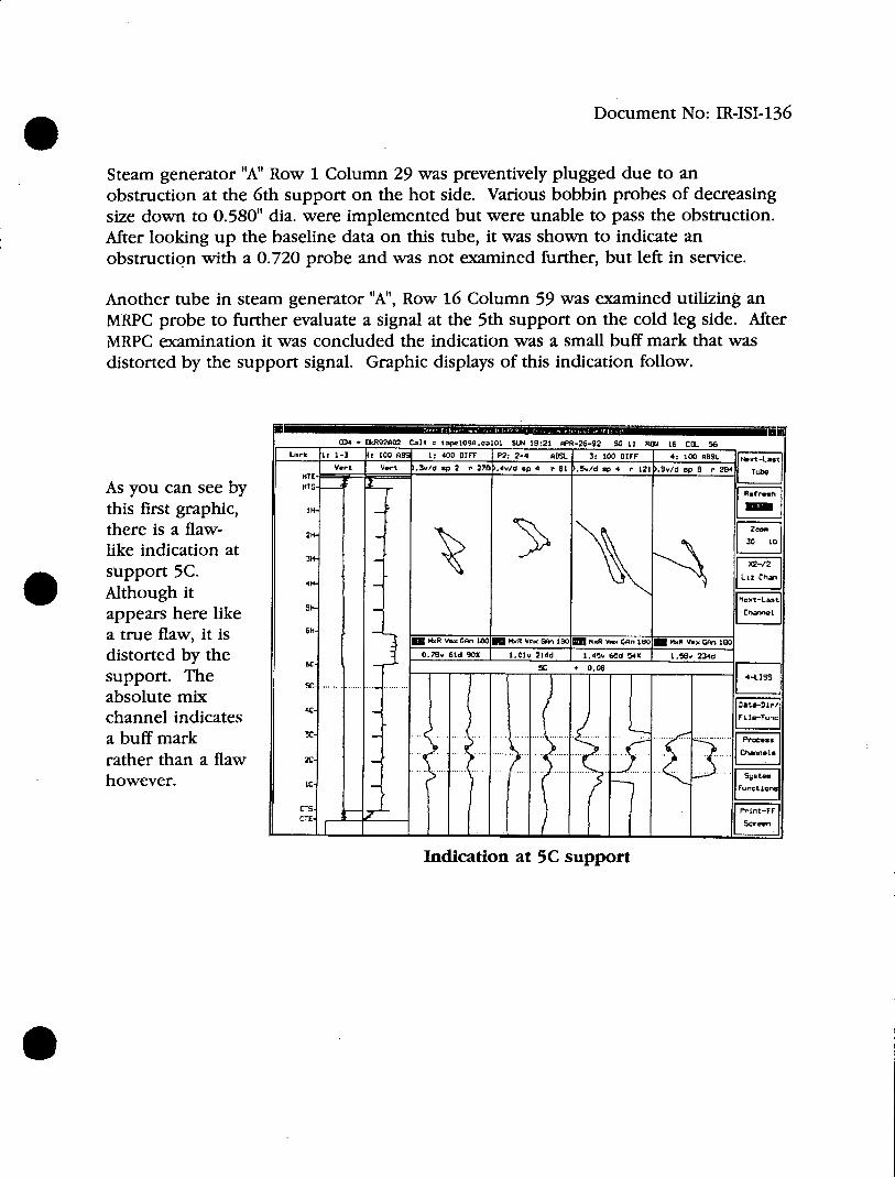
Another tube in steam generator "A", Row 16 Column 59 was examined utilizing an MRPC probe to further evaluate a signal at the 5th support on the cold leg side. After MRPC examination it was concluded the indication was a small buff mark that was distorted by the support signal. Graphic displays of this indication follow.
034 m r&R92A02 C.I. t40 096eajo0 SUN 18:21 PPR-26-92 SG 11 R12A 16 COL. 56_ L ~~1: 1-3 4- 00 ADS 1, 400 SIFT P2-2-4 ARSS 3: 100 01rF 4:100 AmS
VT . =t -- Vvt ).3/d 4 2 r 278 ,4vd 6P 4 ' 51 *34 /d a 4 r121 ).34/4 ap 8 r 284 T ube
As you can see by KTh
this first graphic, there is a flaw- 2
like indication at 301
support 5C. Although it Z appears here like a true flaw, it is 6 M=R 1801- MR V GAn 150 K.R .an
distorted by the 0.78v 61d SOX I.0Iv 214d 1.45 68d 54% 1 Sen 234d
support. The 08LISr
absolute mix 4C
channel indicates _
a buff mark rather than a flaw .. ... ....
.D. .. .. ..k R.2.O 2 C.. ..ap l 0..aO L S N. .:..P-2 - 2.G. .R. O L 5
however. V
HTS-
C1H
Indication at 5C support
Document No: IR-ISI-136
OD. v kit92to2 Cal = tape109A.ca01 SUN 18:21 APR-26-92 SG 11 ROW 16 COL 56
Lark 1: 1-3 M 100 AM8 1, 400 DIFF P2: 2-4 ABSL 3, 100 D1FF 4: 100 A3SL e
Vert Vert .3v/d ep 2 r 270 .7v/d sp 6 r1 .5v/d sp 4 r 121 .5v/dsp I r 264 Tube
HTS. rRefresh
1H.
SH-Charrned
6H4 MR V.x GAn 180 M.R V.x Gun 180 U NxR Vnx GAn 1801M MxR Vmx GAn 100
0.26v 6d 91% 2.64v 215d 0.54v 72d 4L% 6.15v 247d
6c- 3H + 33.6B 4-LISS
5C
4C--- 1e-un
C-
3c- Pr5css
CI
CTE- -Sre
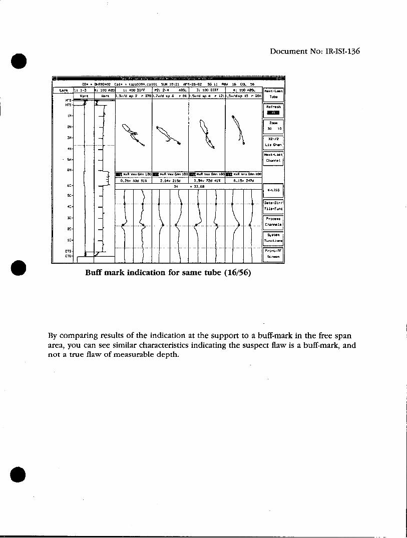
Buff mark indication for same tube (16/56)
By comparing results of the indication at the support to a buff-mark in the free span area, you can see similar characteristics indicating the suspect flaw is a buff-mark, and not a true flaw of measurable depth.
Document No: IR-ISI-136
ON . OkR92AO3 Calm tape401A.eaIOl MON 18:07 APR-27-92 SG 10 ROW 16 COL 56
Larnk 7: 200 PANC 7: 200 PANC span 15 rot 29
Vert 4 of Seans 49 X BY Scalea 1.0 Trig Offset . 31 Filter: Off
-0.84 Points/Scan 120
3
0.9E4 t-o- -- 0 8
0 0.84
Cire Liz
X Rotation a 70,0 X Translation a 0 Z Rotation - 300.0 Y Translaionr - 0
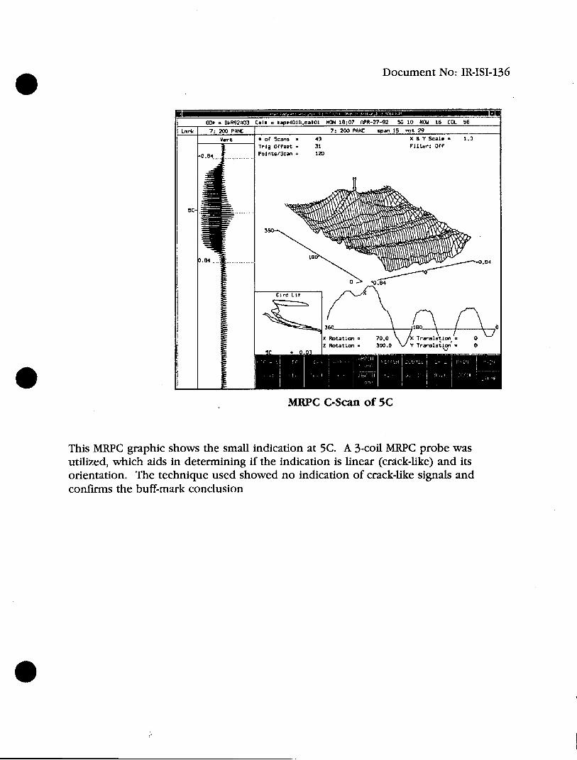
MRPC C-Scan of 5C
This MRPC graphic shows the small indication at 5C. A 3-coil MRPC probe was utilized, which aids in determining if the indication is linear (crack-like) and its orientation. The technique used showed no indication of crack-like signals and confirms the buff-mark conclusion
0I
Document No: IR-ISI-136
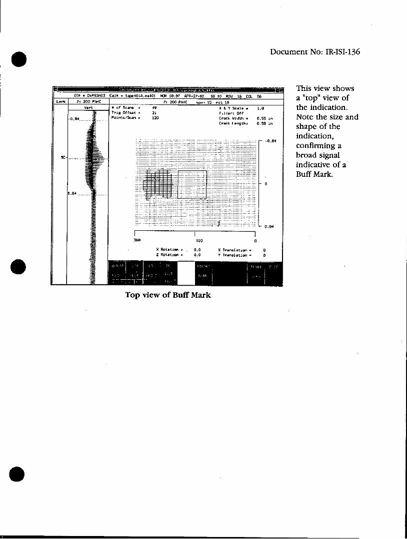
This view shows 0II . DkRS2A03 Cal* - tape401A.cal01 MON 18:0? APR-27-92 SG 20 ROW 16 COL 56 a "top" view of
Lark 7: 200 PANC 7z 200 PANC span 15 rot 18 Vert . of Scans = 49 X & y scale . 1.0 the indication.
Trig Offset = 31 Fiter: Off -0.84 Points/Scan z 120 Crack WWidt = 0 n Note the size and
Crack Length= 0.5. i' shape of the
--0.4 indication, .. .confirming a
sc- . broad signal .. indicative of a
- . Buff Mark. 0
0.84
...... ... 0.94
II I 360 160 0
X Rotation = 0.0 X Translation = 0 Z Rotation = 0.0 Y Translation - 0
Top view of Buff Mark
Document No: IR-ISI-136
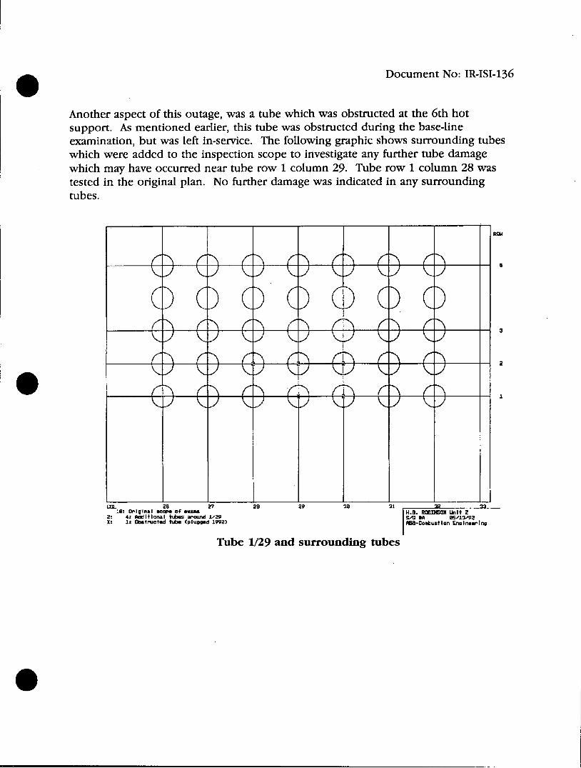
Another aspect of this outage, was a tube which was obstructed at the 6th hot support. As mentioned earlier, this tube was obstructed during the base-line examination, but was left in-service. The following graphic shows surrounding tubes which were added to the inspection scope to investigate any further tube damage which may have occurred near tube row 1 column 29. Tube row 1 column 28 was tested in the original plan. No further damage was indicated in any surrounding tubes.
uOl. 26 27 28 29 38 1IP 3. Ie: Original scape of eam H.B. ROBION 2ktE
2: 4t Md itiona I tubes around 1129 S/*SA 85/1V/92 XI I Obstrwated tube (plugged 1992) AB-Combustion nsinerIng
Tube 1/29 and surrounding tubes
Document No: IR-ISI-136
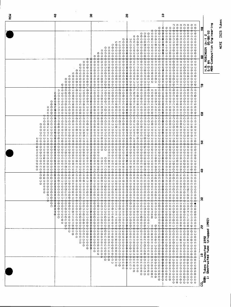
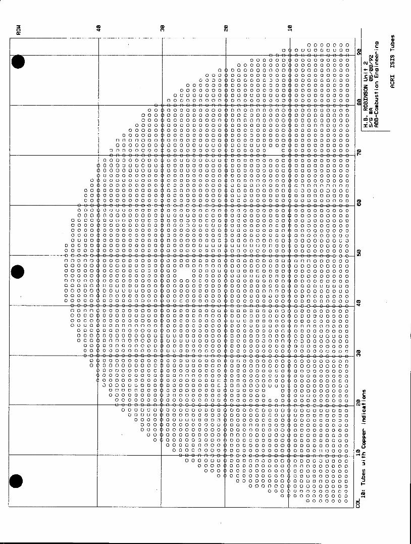
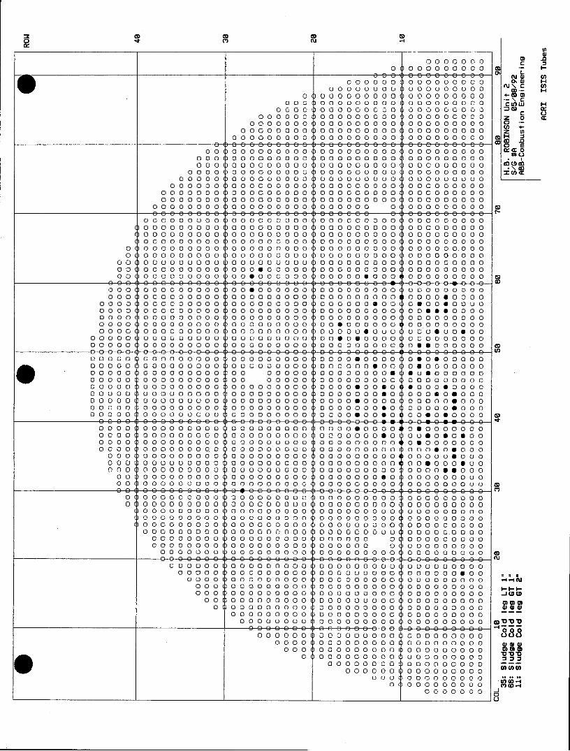
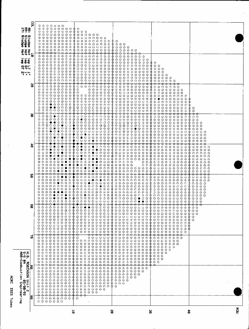
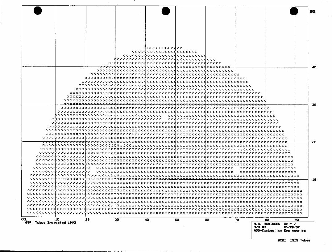
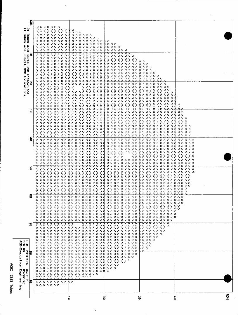
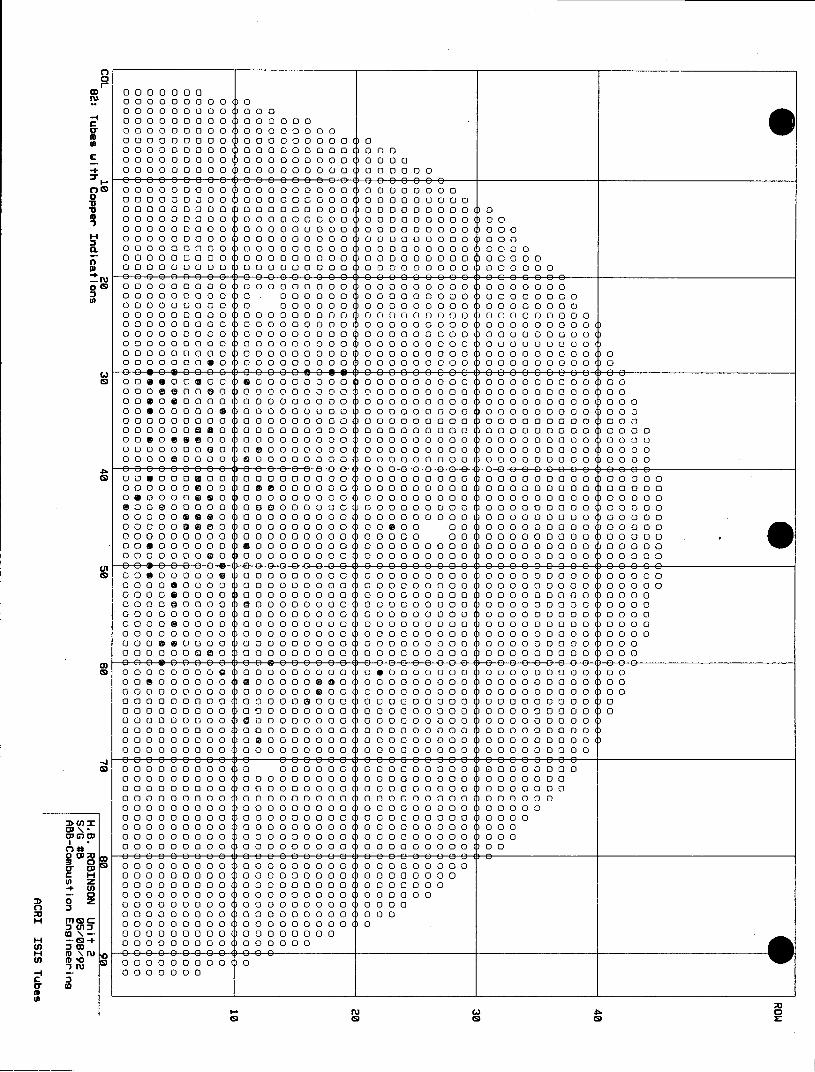
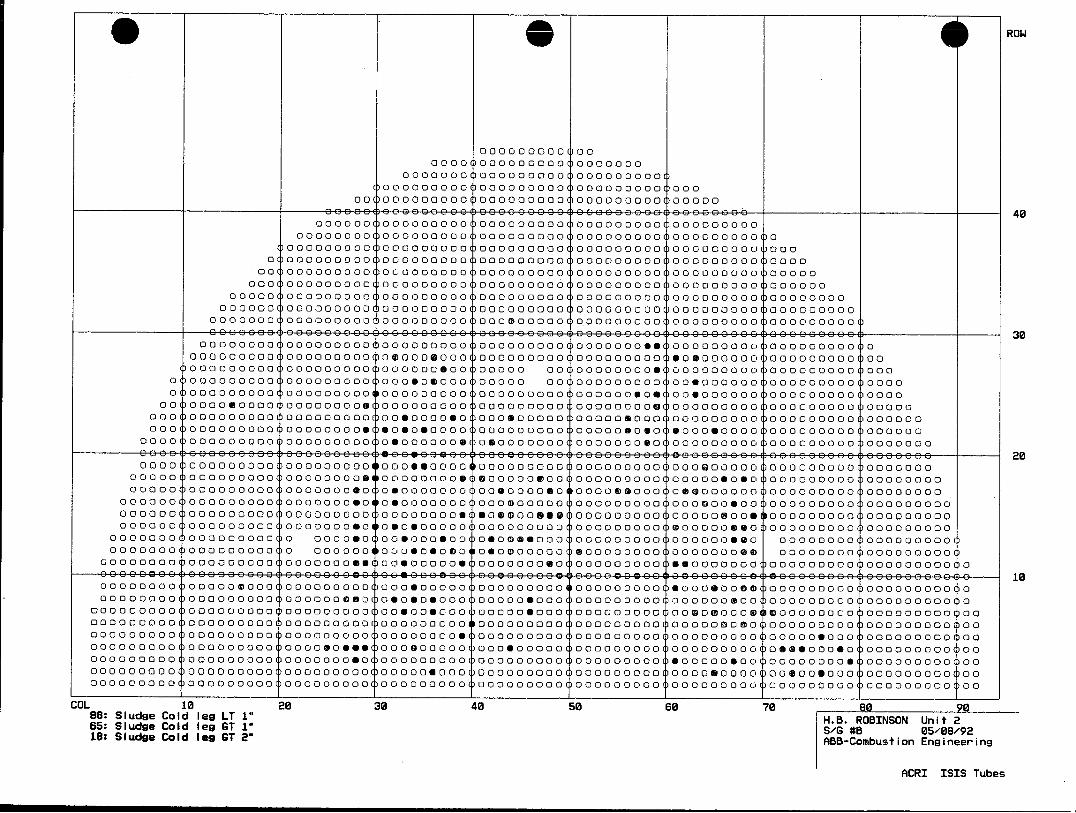
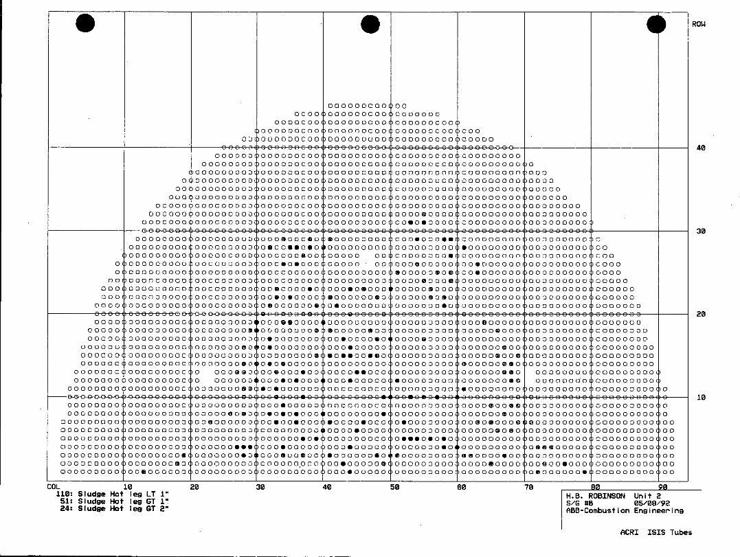
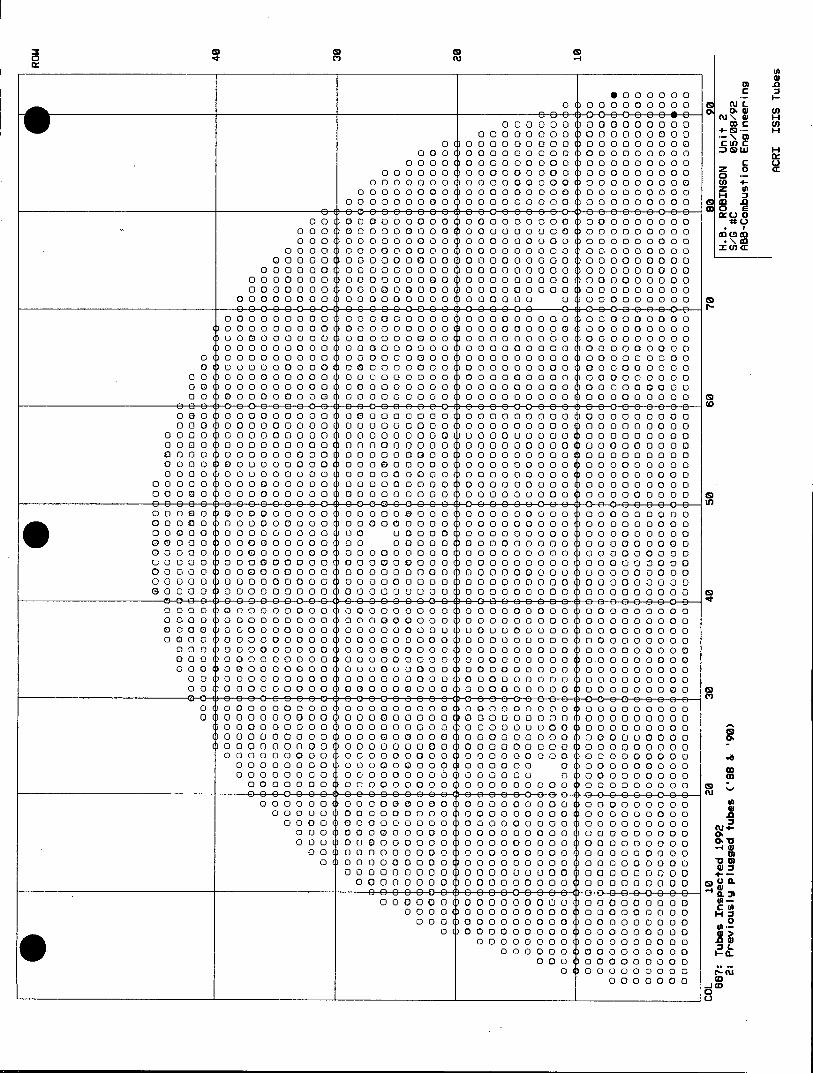
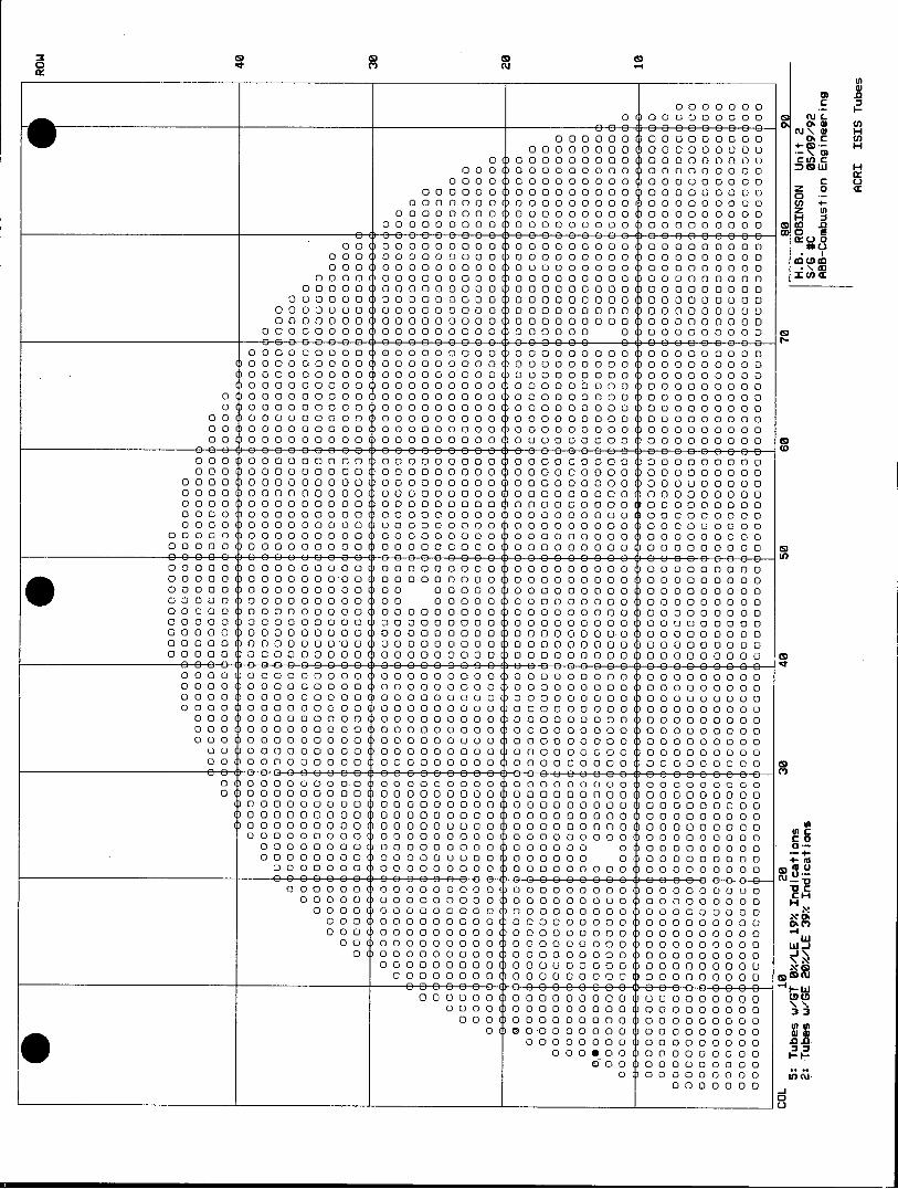
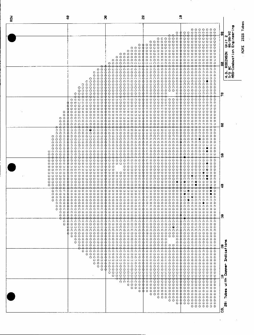
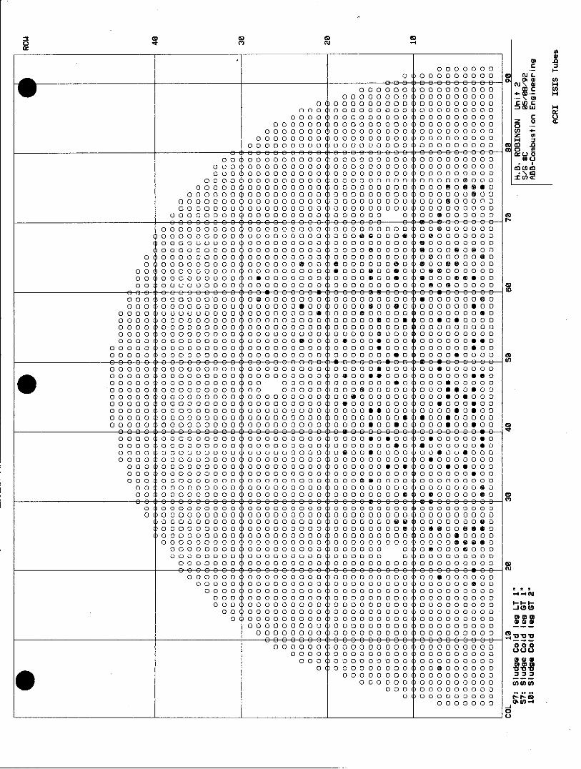
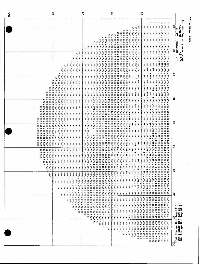
Additional information may be found by reviewing the graphic tube-sheet maps found in the following sections. These include:
All tubes examined Plugged tubes (S/G #A only) Tubes with % through-wall indications Tubes with varying degrees of sludge Tubes with copper indications
All tubes were analyzed for sludge and copper indications as requested by CP & L. The sludge map shows sludge less than 1", 1" to 2", and over 2". There was no sludge reported greater than 3" thick. Sludge less than ~.5" was not reported, due to inability to accurately measure at this level.
0l N
0000000 C .
OOo0eCECoCeCE-- E 0to
0 00 0 00 00 00 00 0 00 Ol W H
O O\ C H 0 00 00 00 00 0 00 00 0 000 0 00 C Ln W H
0 0 00 00 0 000 0 00 0 000 00 0 00 mo
0000000 000000000 0000000000
z 0 q 0 0 i O 000 O 0 0 0 0 0 0 0 0 0 0 C
00 0 000 00 00 00 00 00 0 00 0 00 00 00 0 0 t 0000 00 00 00 00 00 00 00 0 00 0 00 00 0 0 0 0
0000 00 00 00 00 00 000 00 00 ()0 0 0 0 0 0 0 00 000 00 00 00 00 00 00 0 00 00 0 0 C)00 00 0 0 000 .
000000 00 00 00 0 00 00 a00 00 0 00 0 00 00 00 0 0 tDc
0000 00 00 00 00 0 00 00 00 00 0 00 0 00 00 0 0 0 0 m 00000 00 00 00 00 0 00 00 00 00 0 00 00 00 00 00 0
000 00 00 00 00 00 0 00 00 00 00 0 00 00 00 00 00 0 0 00000 00 00 00 0 0 000 0 000 00 0 00 0 000 00 00 0
0 0o0o0o0o0o 00 00 00 0 00 00 00 00 0 00 00 00 00 00 0 0 000 0000 0 00 00 00 00 0 00 00 00000 00 00 00 00 0M
0 00 00 0000 0a0 00 00 0 00 0a0 00 00 00 00 00 00 00 0 00 0 000 00 0 00 00 00 00 0 00 00 00 00 0 00 00 00 00 0 0 0 0 0 0 0 0 00 0 00 00 00 0 00 0c 000 000 00 00 00 00 00 00 00 00 0 00 00 00 00 0 00 00 00 00 00 0
00 00 00 00 000 0a0 00 00 0 00 00 0 000 0 00 00 00 00 00 0 000 00 0 000 0 00 1)00 00 00 0 00 0 00 00 00 00 0 000 0 00 00
0000 )00 00 0 0 000 ()00 00 00 0 00 00 00 00 0 00 00 00 00 00 0 0000 00 00 00 0 00 00 00 0 0 000 00 0 00 0 000 00 0 00 000 0 0000 00 00 00 0 00 00 0 000 0 00 00 00 00 0 00 00 00 0 0 0 0 0
00000 0 0 00 00 00 00 00 00 00 0 00 0a0 00 00 00 00 00 00 00 0 0000 00 00 00 0 00 00 00 00 0 00 00 00 00 0 00 00 00 00 0 0 0
000 00 00 0000 00 00 0 000 00 00 00 0 0 000 0 0 00a0000 0 00 00 00 00 00 0 00 00 00 00 0 00 0 000 0 00 00 0 000 00 00 0 00 000 00 00 00 0 00 00 00 00 0 00 00 00 00 0 00 00 00 00 0 00 00 00 00 00 00 00 00 0 0 0 0 000 00 00 0 00 00 00 00 00 0 00 0 000 00 00 00 00 00 0 0 00 00 00 0 000 00 0 00 00 00 00 00 0 000 0a0 0 000 0 00 )a00a0 0 00 00 00a0 0 00 00 0 000 00 00 0
0 0 0 000 00000000 0000000000 01)0 00000000000o oooo oooo oo c
00 0 00 00 0 00 00 00 )0 0 00 0 00 00 00 00 00 0 00 M00 00 00 00 0 00 0 00 00 00 00 0 00 1)00 00 00 0 00 00 00 00 0 00 ()00 00 00 00 0 0000 0 000 00 00 00 0(30000 00 00 0 000 00 000 00 00 00 0 00 0
0 00 00 00 00 0 0 000 000 0 00 0 00 000000000C 0 00 00 00 00 00 0 00 00 00 0 00 00 00 00 00 0 00 00 00 00 00 0
0 00 00 00 00 0 00 00 00 00 00 0 00 00 00 00 0 00 00 00 00 00 0 0 0 0 00000 0000 0 0 00 000 000000 0D0 00 00 00 00 00 00 00 00 0
0 00 00 00 00 00 0 00 0 0 000 0 000 0 000 00 0 00 00 00 00 00 0 000 00 00 00 0 00 00 00 00 0 00 00 00 00 00 0 00 0 000 00 0 0 0
0 000 0 0 00 00 000 00 0 0 00 000 00 00 00 0 00 00 00 00 00 0 00 00 00 00 00 0 00 00 00 00 0 00 00 00 00 0 00 00 00 00 00 0 00 00 00 00 00 0 00 00 00 00 0.00 00 00 00 0 00 c0 000 00 00 0 00 00 0 000 0 0 000 00 00 00 0 00 00 00 00 0 00 00 00 00 0 0 0
0 00 00 0 000 0 00 00 0 000 0 00 0 000 00 00 0000000000 000 00 00 00 0 00 00 00 00 0 00 0 )0 00 00 00 c00 00 00 0060 000 00 00 00 0 00 00 00 00 0 00 00 00 00 0 00 00 00 00 00 0
000*0 0 0 0 0000 a00 00 00 00 00 00 00 0 00 00 00 00 00 0 0000 00 00 0 00 0 000 00 0 00 0a0 00 00 00 0 00 00 00 00 C
000 00 00 0 00 a00 00 00 00 00 00 00 0 00 0 000 00 000a 00 00 0 00 000 00 00 00 0 00 0 000 00 0 00 000 00 0 00 0
0 00 0 0 0 00 00 00 00 00 00 0 00 00 0 0 00 00 00 00 0 N 0 00 00 00 00 00 0 00 0 0 00 0 00 00 0 0 00 00 00 0 00 00 0 00 0 00000000 0000 000000 0oo 00 00 0000 a 0 0
000 00 00 0 a00 0 000 00 00 00 0 00 00 0 00 0 0 000 C 00 0 00 0 00 00 00 0 00 0 00 000000 )0 00 00 00 00 c 0000 00 0 M00 00 0 00 00 00 00 0000 00 00 00 0 00 0~E
00 00 0 0 0 00 0 0 0 000000000 oooo ooooo oooo
000 00 00 00 00 0 00 00 00 0 00 00 0 000 00 0 00 (D~ 0a00 00aC0 00 00 00 00 00 00 0 00 0 00 00 0 0 0 0 0000 00 00 00 0 00 00 0 000 0 00 00 00 00 0 00 CDD
0000 0 00 00 000 00 00 00 0 00 00 0 000 00 0 0000 00 00 0 00 00 00 00 0 00 00 00 00 0 00 0W
0 0000 00 00 00 00 00 00 0 00 00 00 00 0 00 '00 00 00 00 00 00 00 00 0 00 00 00 00 0 00 nC
0 00 000 00 00 00 00 0 00 00 0 000 0 00 IflL
0 00 000 0 000 00 0 00 0 000 0 000 0M
0 00 00 00 00 00 00 00 00 00 0 00 C+0 00 00 0 000 00 0 000 00 0 0 0H
00000 00 0 )0 000 00 00 0
000 0 00 0 00 0 00
00 00 0 00 -jto
__________________ OOOOOO_____OOOOOOOOO____ OOOOOOOOO___ U
0000000000 a) -0 0 0 0 0 0 0 0 0 0 0 Z I-O
000 0 0000 0 0 0. H 0 00 0000 0 0 0 0 0 0 cu \.C U)
0 00 00 00 0 00 00 00 00 0 00 4- c 0 0 00 00 00 00 0 00 00 00 00 0 00 c Lfl H
0 00 0 00 00 00 0 00 0 000 00 0 00 :3
0 0 0 0 00 000 00 0 0 0 H 000c L
00 0000000000 00 00 00 0 00 z 0 0 000 0000 00 00 00 0 00 0 000 00 0 00 0
00 0 000 00 00 00 00 00 0 00 0 00 0 0 0 0 0 0 0000 00 00 00 00 00 00 00 0 00 00 00 0 0 0 0 0Co
000 0 0 0 0 0 0 0 O 0 i 0 0 0 0 0 0 0 0 0 00000 00 00 0000 0 0M00 0GO00 00 D0 0 00 0 00 0 000000 00 00 00 0 00 00 00 00 0 00 0 00 00 00 0 0 L
0000 00 00 00 00 0 00 00 00 00 0 00 0 00 0 0 0 0 0 0
0 0 000 0 0 0 0 0 0 0 0 0 0 0 0 0 0 0 0 0 0 0 0 0 0 0 0 0 0 0 0 0 0000 001 0O O O 0 0D O 000 0 0 0 0 0 0 0 0 0
0 000 0000 00 00 00 0 00 00 0 000 0 00 00 000 0 00 0 0 000 0000 00 00 00 0 00 00 00 00 0 00 00 00 00 00 0
0 000 00 00 )0 0 00 00 0 00 0 00 00 000 0 0 0 00 0 000 to
00 030 0 0 000 00 0000 00 00 C0 a00 0 00 00 0 00 0 00030 0 00 00 00 00 00 1)00 00 00 0 00 0 000 00 0 00 00 00 00 00 0 00 00 00 0 000 M0 0 00 00 000 0 000 00 0 00 00 00 00 00 0
000 0 000 0 00 00 00 00 00 00 00 00 00 0 00 00 00 00 00 0 000 00 00 00 0 00 00 00 00 0 00 00 00 00 0 00 0 000 00 00 0 000 00 00 0 0 000 00 00 00 0 00 00 00 00 0 00 0 000 00 00 0 0000 (100 00 00 0 00 0 00 00 0 000 00 00 00 0 00 0 000 00 00 0 00 00 00 00 0 00 00 0 000 0 00 0 000 00 0 00 00 00 00 00 0
000 0 000 00 0 00 00 00 00 0 00 00 00 00 0 00 0 000 00 00 00
00 000 00 030 00 00 00 00 0 00 00 0 000 0 0 000 0 000 0 00 0 0 00 000 00 00 0 000 00 00 00 0 00 00 00 00 0 00 00 00 00 00 0
0 0 000 00 00 00 00 00 00 00 0 00 00 00 00 0 00 00 00 0 000 0 00 00 00 00 00 00 00 0 0 00 0 00 00 00 00 0 00 00 00 0 000 0 00 00 0 000 00 00 0 0 0 00 0 00 00 0 000 0 00 00 00 00 00 0 0 00 Q0 000 00 000 0a0 00 00 0 00 D00 0 000 00 C)0 000 00 00 0 00 00 0 000 000 000 00 00 00 0 D00 00 00 00 0D0 00 00 00
0 0 0000 00 00 00 00 00 00 00 0 00 0a00a0 00 00 00 00 00 00 0 00 0 00 (100 00 00 0 00 00 00 00 0 00 00 00 00 0 00 00 00 0 0 00 0
0000 0 10D0 0 00 0 00 )0 00 0 00 000 00 0 00 0 0 00 00 00 00 0 0 0 0 000 0 G00 00 00 0 00 0 0 00 00 0 00 000 0 0 00 00 0 000 0 0 0 00 0 000 0 T00 00 0 0 000 0000 00 00 300 00 00 0 00 00 00 00 00 0 0 00 00 00 00000 0(a000 00 00 0a0 00 00 00 C)00 00 00 00 0 0 00 00 00 00 0 00 00 1)00 00 0 0 000 00 00 00 0 00 00 00 00 00 0 0 00 00 00 0a0 00 00 00 00.00 0 00 00 00 0 00 00 00 0 000 00 0 000 000 00 00 0000 000 00 00 00 0D0 0 00 00 00 T00 00 00 00 0 000 00 00 00 00 0 00 00 00 00 0 00 00 00 00 0 00 ()00 00 00 00 0
D0 00 00 00 00 000 0C0 00 0 00 00 0 000 00 0 00 )0 00 00 0 0 0 0
00 000 00 00 000 00 00 00 00 00 00 00 00 0 00 00 0 00000 00 000 00 0 0000 0 000 00 00 00 0 00 00 0 000 0 030 0 0a0 0 0000 00 00 00 0 00 00 00 00 0 00 0a0 00 00 00 0 000 00 00 0 0000 00 00 00 0 00 00 00 00 0 00 00 00 00 0 00 00 00 00 00 0
00000 0 000 0 00 00 00 00 0 00 00 00 0 00 00 C)00 00 00 00 0 00000 00 00 0 0 000 000 00 00 0D0 00 00 00 00 00 00 00 00 0 0 )00 00 00 0 00 00 00 00 0 00 00 00 00 0 00 0 00 00 0 0 0 0
0 )0 000 00 0 00 00 00 00 0 00 0 l0 00 0 000 00 00 00 0 00 (5o
00 0 00 0 0000 0 0000 00 00 0 00 00 0 0 0 00 0 0 0 0 0 0 00 0 0 0 0 00000 0000 00 00 0 00 00 0 0 0 00 0 0 0 0 0 0
000 00 00 00 00 00 00 0 00 00 00 0 0 000 0 00 0 0 0 0 0 0
O0000OOOOOOOOO0OOOOOOOOO0DOOOOOOOO0OOOOOOOO
00 0 0 0 00 00 00 00 0 00 00 00 00 0 00 0 00 0 0 0 0 00 0000 00 00 0 000 00 0 00 0 00 00 0 000 00 0 0 000 00 Hc 00000 00 000 00 00 00 00 00 00 00 0 00 0 000 00 0 00 C.0o
000000 00 00 00 00 0 00 00 00 00000 0 000 00 0 00 W-4 0 00 00 0 00 0 000 0 00 00 0 000000 0 0 000 00 00 +
0 00 00 0 00 0 00 000 0a0 00 0 000 00 00000 0~
0 00 00 00 00 00 00 00 00 00 0 00 00 00 00 0 00 CH 0 00 00 0 00 00 00 0 000 00 0 00 000 0 0 000 0 X
0 00 00 00 00 00 00 00 00 0 00 00 00 00 0 00 X C
OO)OOOOOOOOO0 000 00000 0000 0000000000
0 00 00 00 0 0 0 00 000 0 00 00 00 0 00 00 Iwu 0 00 00 000 0a0 00 00 00 0 00 0 0 0 0 0 0
0 ) 00 00 000 00 00 00 00 00 00 00 0 00 \ 0 00 00 00 00 0 0 0 00 00 00 00 0 00 X-,
0000000 0000000 0 0 C OO O O O0OO O O n O O O O 0i OOOOOOOOO 0
OO O O O O O O9OO O O l O 0 0 ee 99 G 000 0000000000
OOO OM OOO OO~lOOO OO OOO OO 00 000000000000 c
0 0(00 000001 0 0 0 0 0 ri0 0 0 0 0 0 0 0 0 0 0000
0 00 00 00 0 0 0 011 0 0 0 0 0 0 0 a 0 0 0 0 0 0 0 0 0 0 0 0 0 0 0 0 0 3
OOO HOO OOO OD OOO OOO~n OOO 000 00 0000000 ~
0 ~~~~~0 0 0 O O O OO1 0 0 0 0 0 0 0 0 0 0 0 0 0 0 0 0 0 0 tlOO OO 9O
~~~00000000 0000 0 0 0l OO O O O O O O O 0i DO O OOVOOO O O OO 0) OO O O O 0i OO O O O 0 0 0 0 0 0 0 0 0 0 li OO OO OO
O 10 0000 1000 000 30 0000 0 0 (10 0 0 0 0 0 0 0 0
0 O____OOOOOOOOOO OO__OOOOOO___OO OOOOO )
0 000000000
OOO OO OO OO~l OO OO OO C~w C (U W f0
000 0 000 ()00 00 00 0 00 01- H
0 00 00 00 0 00 ()0 000 00 0 00 +-CDM 0 00 M00 00 00 0 00 C)00 00 00 0 00 CUL)LiW H
0000 000000000 000000000 0
000 00 00 0 000 0 0 000 0 000 00 0 00 H u z 0 C'
00 000 0000 00 00 00 0 00 00 00 00 0 00 0 00 00 000 00 0 000 00 0 00 0 000 00 0 00 z t
00 00 00 00 00 00 00 00 0 00 00 00 00 0 00 CDC.DCD
0000 00 00 00 0 00 00 00 00 0 00 ;0 00 0 0 0 0 0 0
OOO 000 0 0 0000 00000000 . I
00000 00 00 00 0 00 00 a00 00 00 0 00 0 0 0 0 0 0 D
0 0 0 0 0 000 0 00000000 0 00000 0 000000000
00 00 0000 00 00 00 0 00 0 000 00 00D0 00 00 00 00 0 00 00 0000 00 00 00 0 00 00 00 00 0 00 00 00 00 00 0
0 000 00 00 00 0 000 0 00 00 00 00000 00 00 00 0 0 0
0 00 00 00 00 00 00 00 0 00 00 00 00 0 00 00 00 00 00 0 0 00 00 00 00 00 00 00 0 00 0a0 00 00 00 00 00 00 00 0
00 00 00 00 00 00 00 00 0 00 0a0 00 00 00 00 00 00 00 0 00 00 00 00 00 00 00 00 0 00 0 000 00 0 00 00 00 00 00 0
00 00 00 00 0 00 00 00 00 0 00 0 000 0 00 00 00 00 00 0 0 0 00 000 0 0 00 00 00 0 000 0 00 0 00 0 00 000 0 00 0 00 0 0 0
000 00 00 00 0 00 00 00 00 0 00 00 00 00 0 00 0 000 00 00 0
0000 0 00 00 0 000 00 00 0 00 00 0a0 00 00 00 00 00 00 0a0 0000 00 00 00 0 00 00 00 00 0 00 00 00 00 0 00 00 00 00 00 0
000 0 00 00 00000000 ooI ooQ oo0 00 0 000 00 0 000 00 00 0 0 00 00 00 00 0 00 00 00 00 0 00 00 00 00 0 00 0 000 00 00 0
0 0 00 (10 00 00 00 00 00 00 00 0 00 0a0 00 00 00 00 00 00 00 0 00 00 00 00 00 0 00 00 00 00 0 00 00 00 00 0 00 00 00 00 00 0 00 00 00 00 00 0 00 00 00 00 0 00 00 00 00 0 00 00 00 00 0 0 0
00000 00 0 0 00 0G00 00 00 0 00 00 0 000 0 0 000 0 000 00 00 0 00 00 00 00 00 0 00 00 00 00 0 00 00 00 00 0 00 00 00 00 00 0
00 00 00 00 00 0 000 0 0 0 00 0 00 00 00 00 0 00 00 00 00 00 0 00 0 00 00 00 00 00 00 0 0 00 0 00 ()00 00 00 0 00 0 00 00 0 0 00
0 000D0 00 00 00 0 00 00 00 0 000 0 000 00 0 00 00 00 00 00 0 0 0 000 00 00 00 0 00 00 00 00 0 00 00 00 00 0 00 00 00 00 00 0 0 000a0 (100 00 0 0 000 0000 00 00 00 00 00 0 00 00 00 00 0a0 00 00 00000 0000a000 0000 00 a00 00 000 00 00 00 0 00 0 0 00 00 00 00 0 0 000 0 000 00 0 00 0a0 0 000 00 0 00 0 000 0 0 0 00 00 00 00 00 0 00 00 00 00 0 00 00 00 0 0 000 00 00 00 00 0 0 00 00000 0000 00 0 00 000 00 00 0D0 00 00 00 00 00 00 00 00 0 0 00 000 000 00 00 00 000 00 00 0D0 00 00 00 00 00 00 00 00 0 0 00 00 00 00 00 0 00 00 00 00 0 00 )00 00 00 0 00 ()00 00 00 00 0
0 0 0 00 0 000 0 00 1)00 00 00 0 00 00 0 0 00 000 00 0 000 00 0 00 00 00 00 00 0 00 00 00 0 0 000 000 0 00 0 00 00 00 00 00 0 00 00 00 00 00 0 00 00 00 00 0 00 0 000 00 0 00 00 00 00 0 00 00 00 00 00 00 0 00 1)00 00 0 0 000 00 00 00 0 00 0 000 0 00 0 0
0 00 00 00 0 00 00 ()00 00 00 0 00 00 00 00 0 00 00 00 00 0 0 0 000 00 00 00 0 00 M00 00 00 0 00 00 00 00 0 00 00 00 a00 00 000 00 00 00 0 00 00 00 00 0 00 00 00 00 0 00 0 000 00 00 0
0 100 00 00 0 00 00 00 00 0 00 00 00 00 0 00 0 000 00 00 0 0 )00 00 00 0 00 00 0 00 0 000 00 0 0 00 000 00 00 0 000 0
000 00 00 0 00 Q00 00 00 00 0 000 00 0 00 00 00 00 00 0 000 00 00 0 00 00 00 0 00 00 00 00 00 0 00 0 000 00 00 0
00 00 00 00 0 a00 00 00 0 00 0 00 00 0 0 00 00 00 0 0 0 0 00 00 00 00 00 00 00 00 00 0 0 0 0 00 0 00 00 00 0 0 0 00 0 00 0000 00 00 00 0 00 00 00 00 0 00 0 0 00 0 0 00 0
00 00 00 00 0 000 00 0 00 00 00 00 0 00 00 00 0 0 0 00 000 00 00 0 00 000 0 00 0 000 00000 0 000 00 000 0
OOOOOOO 0OOOOOOOO OOOOOOOOO 000000000O
000000 00 00 00 00 0 00 00 00 00000 00 00 00 0 0 0 00000 00 00 00 00 0 00 0 l0 00 00 00 0 00 0 0 0000 L
OOOOOOOO0 0 000O 00 OO000000000 00 000OOOO 1 O O O O0 00 OOOOOOO 000000000 00 00000 0
000000 00 00 0 00 0 0 00 00 000 00 00 00 000 0
O 01 0 0 0 0 0 0 0 00 0 00 0000 0 000000000 OOOOOO 0 0 0 0 0 0 0 0 0 0 0 0 000000000 0 00
0 0 0 0) O O O O0 0000 00000 00 0D O O O O0
0000 00 0 000000 000000000 000000000
0 000 000 00 00 00 0 00 00 00 00 0 0 0 0 00 00 0 0 00 00 00 000 00 00 00 0 00 CD
0 0 0 0 0 0 0 0 0 0 0 0 0 0 0 00
0 00000000 0 DOO OLOO OOO OiO OO OOOiOO OO O0ODOOOOOOO
0000000 (UW Cf
00000 0 0 0 010 H
OO O O OO O O O 10 DO OO O 2 O 0 C cuw U)
0 00 00 0 00 00 00 00 0 00 cu \ H 0 00 0 000 0 00 0 0 0 0 0 0 00 0
0 00 00 00 00 0 00 0 000 00 0 00 C fl W H 0000 0000000 0 0000
000000 000000000 000000000 000000000~~ 00 0 0 0 00 0 0 0c
00 000 0000 00 00 0 0 000 00 00 0 0 000 0 . 00 00 00000 00 a00 00 0 00 00 00 00 0 00 z
0 0 0000 00 0000 0 00000 00C)0 00000 o ( oo 0000 0000 000r0i000 00000000
00000 0 00 0 00 000 00 00 00 0 00 0 00 000 0 00 I 000 00 00 0 00 000 00 0 00 00 0 0 00 00 00 0 00 igCDc
0000 00 00 00 0 00 00 00 00 00 0 00 0 0 00 0 0 0 0 0 00000 00 00 00 00 0 00 00 00 00 0 00 0 000 00 00 0
000 00 00 00 00 00 0 00 00 00 00 0 00 00 00 00 00 0
0 000 0000 00 0 000 0 00 00 00 00 0 00 00 00 00 00 0 0 0000000 0a0 00 00 0 00 00 00 00 0 00 0 000 00 00 0
0 000 0000 0 00 00 00 00 000 00 00000 0 00 00 0 0 0 0
00 00 00 0000 00 0600 00 00 0a0 00 00 00 00 00 00 00 0 00 00 0 000 00 a0060 00 0 00 00 00 0600 00 00 00 00 0 0 0
OC~~ccO uOOcOOOO OOOOOOOOO COOOOOOOOOC
00 0 000 00 00 0060 00 00 00 00 00 00 0 00 00 00 00 00 0 00 00 00 00 00 00 0 000 0 00 00 00 00 0 00 ooooeooo0o 0
000 00 00 00 0 00 00 00 0 00 00 0 00 00 060 00 0U00 0 0 000 000 00 00 00 0 00 1)00 00 00 0 00 0 000 00 0 00 00 0060 0 0 0
000 00 0 00 00 00 0 )a00 00 00 00 00 00 00 0 00 00 00 00 00 0 000 00 00 00 00 0M0 00 a0 0 000 0 0600 0 )0 00 00 00 00 00 0
0000 0 0 0000000 0a00D000 0000000 O0000000
e-OOOOOOO ete(E))O OOOOOOenOOOOOOO l OOOOOOO
000 00 0 0 00 000 00 a00 0000 00 00 00 0 00 060 00 0 00 0
000 0OOOOOOOOOOOOOOO 0 0 0 000000000
00 00 M00 00 00 0 00 00 00 00 0 00 M0 0 0060 0a00 06a060a0 00 0 00 00 0 00 00 0 000 00 0 000 00 00 00 0 0 0 000 060 0 00 000 0 0 0 00 00 000 00 00 0 0 000 0 000 00 00 600 00 00 00 00 0 00 0 00 00 00 G0 000 00 0 00 0G0 00 00 00 0 000 00 00 0 00 00 00 00 00 00 00 00 00 00 00 0 00 06a0 0 060 0060 0a0 0
00 0 00 00 00 00 0 00 00 00 00 0 00 000a0 a00 000 00 06060 000 00 0 00 0 0 0 00 0 0 0 0000000 0 0 00
0000 000 0000 000 0000 000 0000 00000 0
00 0 OOOOOOO 000DOOOO OOOOOOOOO li OOOO O
0000~~~~~~ 00000 00000 0060 0 000 0000~~ 000000 00000 0000000 000
00 00 0 )00 0 000 0 00 00 00 00 0 00 0 000 a0 000 0a00a0 000 0 00 00 0 )00 00 00 0 00 00 00 00 0 00 00 0 0 00 000 0a060 0060 00 00 00 0(100 00 00 0 00 0000 0 000 0000 00 0 00 aa00a006600 00
0000 0 )00 00 00 0 00 0000 00 00 00 00 00 0600 00 00 0 000 0 00 0 0 0 00 00 0 00 0 000 00 0 00 00 00 0 00 00 0 0 0 0 0 0000 0 0 00 M0 000 00 0 00 0 0 000 00 00 0 0 0000 00()0 00 a0a000 0 0 0 )00 0 000 0 00 00 00 00 0 00 00 00 00 0 00 00D00 060 00 0 0 )00 00 00 0 00 00 00 00 0 00 00 00 00 0 00 00 00 0 000 0 0 00 000 00 00 00 00 00 00 00 0 00 00 00 a00 00 0 0 00 0 00 0 0
0 300 00 0 00 0 0 00 00 00 0 00 00 00 0 00 00 0a0 0 000 00
0 )0000 00000 000000000 0000000i0 000000
0 0000 00 00 00 00 0 00 000 00 00 0 0 000 0 0 0 000 00 00 0 0 00 000 00 0 0 000 00 00 00 00 00 0 00 00 0 0 0000a0 a0 00
0 00 000 00 00 00 00 00 00 0 00 00 00 00 0 00 00 00 0a000 0
0 00 000 00 00 0 M00 00 00 0 00 00 00 00 0 00 000a0 0 0 00 0 00 000 00 00 00 00 00 0 00 00 00 00 0 00 0 00 00a000 0 :
0 0 00 00 00 00 00 00 00 0 00 00 00 00 0 00 0 00 0 0 0 0 0 0 0 00 0 00 0 00 00 00 0 00 00 00 00 00 0 00 00 00 00 0 00 (D-I
0 00 00 000 000 0 0 0 0 0 000 00 0 0 0 0 00oo ooooo oobo 0 00 0 00 00 00 00 00 0 00 00 00 00 0 00 00 00 0 0 0 0 0
OOOOOOO0 00000000 000000000 00000000 0
T 00 00 0a00 0 00 000 0 000 00 0 00 00 00 00 0 00 0 00 00 00 00 0 000 00 00 00 00 0 00 0 0 0 0 0 00 0 0
0 00 0 00 1)0 00 000 00 000 0 00 0 00 0 000 0.0 000
O 000 00a000000 0000 0000 1) 0D O O
0 00 00 00 00 00 00 00 00 00000 0 00 0 0 00 0 0 0 00 00 00 000 00 0 000 00 0 00 00 0 000 0 00 wwo
OO <10 000 0 0 0 0 0 00 0 0 0 0 0 0 OOOOO*OOOOOOOO00OOOOOOOOO
0 00 00 00 00 00 0 00 000 00 00 00 00 a00 0 00 00 00 00 00 00 00 00 0 00 0 0 0 0 0 0
OOO 00 00000 0 0 0 0 0 0 0 0 0 0 OO OOOO0 000, O
OOOOO9OOO OOOO9l)O OOOOOOOsOOOOOOO O eOOOOOO e .
O O 00000000
0 M
OOOOO 01 O O 0 OOOOOOO 0 0 0 0__ 0_0_0_0_zz
DOOO 0OOOOOOOO OOOOOOOOO0DOO00 0 0*DOO OOO O O O O O0OO O O O O O O O O O O O O O0OO O O O O0O0O O0OMO O
00 0 0 0 01 OO O O O 0I OO O O O O O O O O cOOO O OOO nO OOO OO OOO OO OOO DO OOO O0io o o o o o o
OOO 1 O OOO OOO OOOO OOO OOO OOO OO 0 OO OO OO OOOO OOO OOOO1)OOOOO OOO OOO OOOO BOO* 0 0 0
0000000 I 0'0 00 0000 0
D 000000000 000 0C)C 0 00i0 00 00 0 0000
000000000 )00000000 000000 0 )OOOOOOOO 0000 0 0 000000 0 000 00 000 0 00
FF 000000000 000000000 000000
(a 000000000 000000000 000 I 00000 0000a00 00 00 00 00 000000 0
T x x 00 000 0 00 0 00 00 00 00 00 000 0 0 0 -44- 000000 0000 0 00000 0 00 0 00 000 0 00
00 00 0000 00 00 0000 00 00 0000 000
( 00 00 00 0 00 00 00 00 0 00 00 00 00 0 00 000 a 00 00 00 0 00 00 00 00 0 00 00 00 00 0 00 0 000
1-- 00 0000 00 0 00000 0a 0 00 000 00 0 0000 r 00 00 00 00 00 0 0 00 0 00 00 0 000 0 00 0 00000
00 00 00 00 00 0 0 00 0 00 00 00 0 0 000 0 00 000 00 00000 000 00 0 000 00 00 00000 0 0C)0 000 00. 00 00 00 00a0 00 00 00 0 00 00 00 00 00 00 0600 0000
000 00 00 00a0 00 00 00 0 00 00 00 00 0 00 00 00 00 00 00 0600 00 00 0000 00 00 00 00 00 0 00 00 00 00 000
QOOOOOOOO )D000000 00000000 00000000 0
00 00 00 0 00 00 00 00 0 00 00 00 00 0 00 0 00 00 00 00.0 0 00 0 060 000 00 00 0 00 00 00 00 0 0 000 0a0 00 000 00
00 00 00 0 00 0600 00 00 00 00 00 00 0 00 00 00 0000 00 00 0a60 00 00 00 00 00 0 00 00 00 00 0 00 00 00 0000 000 00 00aa00 00 00 00000 00 00 0000 00 00 0000 000 0 00 0600 0000 000 00 00 0a0 000 000 00 00 00 00 0 00 00
C00 060600 00 00 00 00 0 00 00 00 00 0 00 00 00 0000 0 )000 0 00 00 00 000 0 06000 0 00 00 00 00 0 00 00 00 00 0 00 0 00 00 00aa00 00 0 000 00 0 00 00 00 00 0 00 00 00 00 0 00 0 000 00 00 00 00a0 00 0060 00 00 00 00 00 0 00 00 00 00 0 00 0 000
0 000 060 0 a00 060060 00 00 00 00 0a0 00 00 00 00 0 00 00 00 0 0 06a0a0 00 0600 000 0 a0 0 00 00 000 00 00 00 0 00 00 000
SOOOO 00000000 000000000 000000000 00 000
0o0ogouo0oo0 0 a00 00 0 00 00 00 00 0 00 Q00 00 00 0 00 00 000 0 0 0060 0060 060066 00 00 00 00 0 0 000 ()00 00 0 0 000 00 000
0 0 0 0a0 0000 000000 00 000 0 0 0 00 00 00 0 00 00 00 0 00 0a0 00a0 *0 000 000C0 000 0 0 0 00 00 00 0 00 00 00 0
00 090 0 000 00 00 a00 00 00 00 00 0 00 00 00 00 0 00 00 00 0 0 00 00oa0o00o oo0o00a0eo0o 00 00 00 0 00 0 0 0 00 0 000 0 0 0 00 0 0 0 0a0 00 0 0a0 000a0 00 00 00 00 0 00 00 00 00 0 00 0 00 00 00 00 00 0 00 00 00 0a000 a00 00 0000 C)00 00 00 0 00 0 0 0 0 00 00000 06w0 00a0 0 00 00 00 0000 00 00 0 0 000 0 00 00 00 00060 a0 00 00 0 00 00 00 00 00 0 00 00 00 00 0 00 0 0 000 0 00 060 06a0 00 00 00 0 00 00 00a0 0 00 (100 00 0 0 000 0 0 000
000 0 00 0 06a00 0000 0 0 0C00 0000 0 0600 0 00 00 0 0 0 0 00 00 0 000 0 00 00 00 a00a0 00 0 0 0 00 0660 0 000 00 00 1)00 000 00) 000 0, 0 ~00 0 0a0 0 00 030 00 0(100 0 00 0 00 0 1 0) 00 00 0 000 0060 0 0 0a00 00 00 00 0 00 00 00 00 0 00 0 000 00 00 00 0 00 00 00 00 0 00 00 00 00 0 00 00 00 0 00 00 0 000 00 00 a00a00 00 00 00 0 00 00 00 00 0 00 0 000 00 0 00 0 000 0 0 00a0 000 00 a00 00 00 00 00 00 000D 00 00 00 0 00 00 0 00 00 00 00a0 00 00 00 0 00 00 00 00 a00 00 00 00 0 00 000 00 00 00 0 00 00 00 00 0 00 00 00 00 0 00 00 00 00 00 0000
000 00 0 0 00t0 0000a0 0 0 0 00 00 00 00 0 00 00 00 00 00 0000 00 00 00 00a0 00 0 000 0 00 0 00 00 00 00(00 00 00 0 001 00 00 00 00a0 00 00 00 00 a0 000 00 00 )0 0 0 0 0 0 0 0 0 0 ~0 0 0 ~0 00o0000000000000000000 000 0 0 0 0C0030 0
0) 00 0 000 00 0 0 0 00 0 00 00 0 000 0 00 00 00 0 0 0 0 0 00 00 00 00a0 00 00 00 0 00 00 00 00 0 00 0 00 0 0 0 0 0 00 00 00 0 00 00 00 00 0 00 00 00 00 0 00 00 00 00 000
00 0 000 00 0 0 00000 000000000 000000 000000000 000000000 000000000 0000000
G 000000000 000O00000 000000000 0 0 0 0 0 0 0 0
0o~ 00 00 00 00 00 00 00 0 00 0 00 00 0 0 00 00 00000 0 00 00 00 00 00 00 00 0 00 0 00 000 0 00 00 00000
0 00 00 00 00 000 00000 00 M000 00000 00 000 00 0
0 0 0 0 0 0 0 0 0 C0 0 0 0 0 0 0 0C 0 0 0 0 0 0 0 0 0 0 0 0 0 0
3) H) 00 00 00 00 0 000 000 0 0 0 0 )00 0 0 0 0 0100 zDO 00 00 00 00 0000 0000 0 0 0 000 0000 0 0 0 (
0o0o0o0o0o0o0o0o0 0o00o00000o0 0000000000 0 ooooooooo ooooooooo 000o0000o00 000o000
9 000000000 0000000000 000000000 000000000ee00
H H 0J1 0 00 0 0 0 00 00 0 0 0 00 00 o0 0 0 0000 to z-4 00 00 0 0 000 0 000 00 0 00 00000000
H -0 00 00 0 0 000 0 00 00 0 0 00000000 M 0 o 00 00 00 0 00 0 00 0 0 000000000
0 :0
O O D O 0 0 0 0 0 0 0 0 0 0 O OOOO
OO O O O m OO 0 0 0 0 0 0 0 D O O O O O OO O O O O O OOOOSmOOOO OOOOD- eO OOOOODeOO OOOOO uOOO O o oO OO O OO O OO OO OO000 00 00 00 0
0 OO OB OO0SO SOO0O OO OO D)O OO O O OO O OO O O O S O O O fO OO O O O O O O O O O O OO B O O lO O B O O O OO O O H O O OOmO O OOtoO O S O OO O O O O O O OO O O O O O O
00 0 0 0 00 0W0 0 0 0 0 00000 00 0 0 0 0 OOO OO COO O9OO O O O OOt O O O O n O O
* . *ROW
000000000000 0000)000000000 0000000
0000000000000000 OOOOOOOOOO 000000000 000000000 0000000000000
00 000000000 000000000 000000000000000 conooocoooooonocoooooooooooooooci00000 4 - - - - -- GG-G Gee099e 940 000000000000000 000000000 00000000O 000000000
00000000 0000000000000000000 000000000 000000000 0 0000000000 000000000 0000000000000000000 000000000 000
0000000000 000000000000000000000000000 OOO0OO000Oooo
00000000000 000000000000000000000000000 00000000000000 0000000000000 000000000()000000000()000000000 000000000()000000
00000M000000000 000000000()0000000000000000000 00000000000000000 000000()000000000 0000000000000000000 000000000 000000000()000000000
00000000000000000 0000000000000000000 000000000 00000000000000000000 cooocooooooo coooooooooooooooooooooo ooocooooonoooOOOO8
00000000 000000000 000000000()000000000()000000000()000000000()000000000()0
0000000000000000000M000000000 000000000()000000000()000000000()000000000()00 000000000000000000 OOOOOOODOO O 00000 00000000000000000000 000000000000
0 000000000M000000000M000000000 00000 0000000000000000000000 000000000 0000 0 0000000000000000000 000000000 000000000M000000000000000000 000000000 00000
00 000000000 000000000 000000O~o0 000000000 000000000 )000000000 000000000@00000 000 000000000 000000000 000000OC00 0)00000000 0000000000000000000 10000000000000000 000 oooooooo0ooooooclo ooooo0ooo0ooooooooo oooooooocoooooooooooooooooo
0000 000000000000000000D000000000000000000 OOOOOOOOOOOOOOOOOO0000000000000000
000000000O000000000000000000 000000000 OOOOOOOOOOOOOOOOOO 0000000000000000 0000000 0000000000000000000000000 000000000()000000000()000000000()000000000()000000000 0000 00000 000000000M000000000 000000000000000000 OOOOOOOOOOOOOOOOOOOOOOO0000000000
00000n00000000000000000000000000 000000000O OOOOOOOOOO000000000 000000000000000000 000000000000000 00000000000000000000000000000000OOOOOOOOOOOOOO 000000000000000000 000000000000000 000000000 000000000000000000000000000000000000 000000000 000000000
00000000000000000 0 000000 000000000()000000000()000000000 000000000 00000000 000000000 00000000000000000 0 000000 000000000 0000000000000000000 000000000 00000000 0000000000
000000000000000000 000000000 000000000 0000000000000000000 000000000 000000000 000000000 0 00000000 o cooccoco-- oco co io --- - opo-- -- -- -- -- -- ---------o --------- Ioc o c --------- c -- cc c ----- - 10
00000000()000000000()000000000()000000000 000000000 000000000()000000000()000000000()000000000 0 00000000000000000000000000OOOOODOOOO 000000000000000000000000000000000000H000000000 0
000000000 000000000000000000 0000000000OOOOOOOOOOOOOOOOO-00000000000 000000000000000000 00 000000000 000000000000000000OOOOOOOOO OOOOOOOOO OOOOOOOOOOOOOO000000000000 OOOOOOOOOOO 00 0000000000000000000 000000000 000000000 )000000000 )000000000 )000000000 )000000000 )000000000 )00 000000000000000000 000000000 000000000000000000000000000 00000000000000000000000000000 000000000000000000 000000000 000000000 0000000000000000000 000000000 0000000000000000000 00 0000000000000000000 000000000 000000000 0000000000000000000 000000000 000000000 00000000000 000000000 000000000 000000000 000000000 0000000000000000000 000000000 000000000 000000000 00
COL 10 20 30 40 58 68 70 so 90 659: Tubes Inspected 1992 H.B. ROBINSON Unit 2
S/G #B 95/08/92 ABB-Combust ion Engineer i ng
ACRI ISIS Tubes
0
OOOO OOOO000
0
000000000 000 00 CC 0 0 00 000000 0 OO 0000 0 00000000 00 )
0m 0 0 00 0 000 0 a000000
000000000 1000000000 00 cc 000000000 000000000 0000 m m 000000 000010 00 0 0 0a00 0000
OP t 0 00 00 00 00 0 00 00 00 00D0 0 00000 cc00 00 00 0 00 00 00 00 0 00 00 00000
\F 00 00000 000 00 00 00 00 00 00000 0
ruo00 00000 00 00 0000 00 00 0000 00 I0 00 000000 00 00 00 00 00 00 00 0000 000
0 0 00 00 000 00 00 00 0 00 0 000 00 0 00 00 rm00 00 0 00 00 00 00 00 0 00 00 00 00 0 00 0 00 m 00 00 00 0 00 00 00 00 0 00 00 0 000 0 00 00 00
W10 00 0 00 00 00 00 00 00 0 00 00 0a0 00 00 0 0000
v X~ 00 00 00 0 00 00 00 00 0 00 00 D0 000 00 00 0000
0 000000000 0 000 00O0 000000O00 0000
\r 0 0 0 0 0 0 0 0 0 000000000 0 00 0 0000
3 L00 00000 00 00 000 0M0 00 000 00 00 000 0
OOOOODOOOOOOOOOOOOOO00 OOOOOOOOO 0 00 30OO3
0 00000 0C000 00 0 000 00 0 000 0 00 00 00 0000 00 000000 0a000 00 00 00 00 00 00 0 00 00 00 0000 00 00 00 0000 00 00 0000 00 00 0000 00 00 0000 000
0 0 000000 00 00 0000 00 00 0000 00 00 0000 000 000000 0a000 00 00 00 00 00 00 00 0 00 00 0000 0 000 0 00 00000 000 00 00 00 00 00 00000 00 00 00 0 00 000 00 00000 0.)00 00 00 00 0 )00 00 00 0 00 00 00 00 a00 000 0 0 000000 0 )0 00 0000 0 )0 0 00000 00 00 0000 0000
co 00 0 000 0 00 00 00 0 00 00 0 0C)00 00 00 00 00 00 0 00 0000 00 00 00 a00 00 0 0 00 000 00 00 00 0 00 00 00 00 0 00 0000 00 00 0 00 00 00 00 00 0 00 00 00 00 0 00 00 00 00 0 00 00 00 00 00 00 a00 0 00 00 0 0.00 00 00 00 0 00 00 0 0 00 000 00 00 0 000 0 00 00 00 00 0000 0a0 0a0 00 00 00 00 a0a00 00 00 00 00 00 0 00 00 0 00 0 0 00 0 0 0 00 0 0 0 0 000 0 000 0 0000 00 00 00 0 00 00 00 00 00 00 00 00 0 0 0 00 00 0 0 000 00 000
00 00 00 0 00 00 00 0 00 00 00 00 00 0 00 00 00 0 0 000 00 000 00 00 0 00 00 00 00 00 0 00 00 0 000 0 00 00 00 0 0 000 0 00 00
(00 00 00 0 00 00 0 00 00 00 00 00 0 00 00 00 0 00 00 00 0 00 00 00 00 00 a00 00 00 0 00 00 00 00 0 0 000 0 000 00 0 00 0 00 00 0 000 0 0000 0a0 00 00 0 00 00 00 00 0 00 00 00 00 0 00 0 0 0 0 00 00 00 a00 00 00 00 0.00 00 0 000 0 00 00 00 00 0 00 0 00 00 00 00 0 0 000 00 00 00 0 00 00 00 00 0 00 00 00 0 0 000 00 000 00 00 0 0000 0a0 00 00 0 00 00 00 0000 00 00 00 0 00 00 000
0 00 00 00 00 00 00 00 0 00 00 00 0000 00 00 00 0 00 0 0000 00 00 0 00 00 00 00 00 0 00 M0 0 00 00 000 00 0 000 a00 0 00 0 00 00 00 0 0 00 000 0 0 00 00 0000 00 0000 0000 00 0000 00 0
0 0 00 00 0000 00 00 00 0 00 00 00 00 0 00 00 00 0 00 00 00 00 00 00 00 0 00 00 00 00 0 00 00 00 00 0 00 00 00 00 0 00 0 0000 00 00 00 0 00 00 00 00 0 00 00 00 00 0 00 0 000 0 000 00000 00 00 0 00 00 00 00 0 00 00 00 00 00 0 00 00 00 00 00 00000 00 00 00 0 00 00 00 00 0 00 00 0 000 0 00 00 00 00 0 0 0000 00 00 0 0 000 0 00 00 0 000 00 00 00 0 00 000 00 0 00 00000
0 00 00 0 000 0 0 0 00 0 00 00 0 000 0 00 0 00 00 00 000000 00 00 00 000 0a0 00 00 0 00 00 00 00 0 00 00 00 00 000000 00 00 0 0000 0a0 00 00 0 00 00 0 000 0 00 00 00 0 0 00000
(00 00 00 0 00 00 00 00 0 00 00 00 00 0 00 0 00 00 000000 00 00 00 0 00 0 000 00 0 00 00 00 00 0 00 00 00 0000000 00 00 00 0 00 0 000 00 0 00 00 0 000 0 00 0 0 000000000 00 00 00 0 00 0 00 00 0 000 000 a0 0 000 0 0 C0 0000
0G, 00 00 0000 0a0 0 000 0 00 00 00 00 0 00 0 0 0000000 0~* 0O0oo0o0oo0o 00 00 0 0 000 00 00 00 0 00 0 0000 000
00 0 000 0 00 00 00 00 0 00 00 00 0 0 00 000000a00 C H 00 00 0000 00 00 00 0 00 0 0 00 0 0 0 000000000
ID 0 00 0 00 00)0 0000 00 00 0 0 00 0 0 00 000000
0* 00 00 0 000 00 00 00 0 00 0 0 0 0 0 000000000 0 0 00 00 000 00 00 00 0 00 0 00 0000000000000
0 0 00 00 000 00 0 000 0 00 0 0 000 00000000 0 0 00 00 0000 00 00 00 0 00 000 0000000000
M \- 00 00 00 0 00 0 00 0 0 00 0000000000000 H 5. 0 00 0 000 00 0 00 0 0 000000000000000
H HDf 00 00 00 G00 0 0000000000000000
tOOOOOOOO 0OOOOOOOOOOOOOOOOOOO0OOO
-0 () 00 00 0 000 0 00 OOOOOO OOOOO OO0nO OOOOO
OO OO OO \O 0- 0001 0 0 0 0 0 0 0 0 1 0 0 0 0 0 0 0 0 0 )
0 - t 0 0 0 0 0 0 0 0 0 0 0 0 0 0 0 OlOO0
H ) O OOOOOOOee eo O O OOOeOO O OO O O OO O eO O
OO O D OO O O O 0.0 O O O O O n O O O O 1 OOOO OO O O O nO O O O (O O O OO O O O OOaO O OO O OOmO O O O l DO O(OO O O O n O O OO OO OO ( O O O OO O OvOO OO O O n O O
OO OO O~n O OO O OD O OO OO (1 0 0 0 0 00 0 OO OO OO OO OO OO ctOO OO O oO O O OO O O O
0 r OD 00 00 00 0
00 00 00 0 00 00 0
0 00 000000 0 000 0000 0 cr00 00 0000 00 0 000 00 0
000000000 000000000 0000
O 000000000 00O0O00000 000 O 000 0 0 0 0 0 0 0 0 0 0 0 0 0 0 0 0 0 00 ococooooooI o o coco o oo o ccooo
no 000000000 00000000i0 00000000
0U 0 000 0 0 000 0 000 00 0 00 00 00 0 0000 0 M 00 0 00 0 000 0 000 00 D00 00 00 00 0 00 00
00 00 00 0 00 00 00 00 0 00 00 00 00 0 00 000 00 00 0 0 000 00 00 00 0 00 00 0a0 00 00 00 0
0H 00 00 00 0 00 00 00 00 0 00 0 00a0 00 00 0 000
0L 00 00 00 a00 00 00 0 0 000 0 00a0 00 00 0 0 000
0 0 00 00C0 00 00 00 00 0 00 00 00 00 0 00 00 00 00 a)00 00 0 000 0 0 0 00 000 0 0 0D0 00 0 00 0 0 000 00
00 0 0 0 0 0 0 0 000 0 00 0 0 0 0 000 00 0 00 0 00 00 000 30 0 0 00 0 000 000 0 0000 00 00 00 0 00 00 00 00 000
to00 00 00 0 00 0000 00 00 00 00 00 0 00 00 00 00 000 00 00 00 0 00 00 00 00 0 00 00 00 00 0 00 00 00 00 00 0 00 00 00 0 00 00 00 0 00 00 00 0 000 0 00 00 00 00 00 0 00 00 00 000 00 00 00 0 00 00 00 00 0 00 00 00 00 0 00 0 00 00 00 0600 00 00 00 0 00 00 0 000 0 00 00 00 0 0000 0
0 0 0,0 0 0a00 060 00 00 0 00 00 00 00 0 00 00 00 0 0 000 00 0 0000OoDO 0 0 0 0 0 0 0 00 00 0000000 1 0 0 0 0 0 0000
oo aae 0 00o 00 00 00 00 00 00 00 0 00 00 00 0 00 00 0 00 00 080 00 00 060 00 00 00 0C)00 00 a00 00 00 00 0D0 00 0 00
0oooo 0 0aooo00oo000 oo00 000 a0 00 00 00 00 00 0 00 0 000
O DOOOOOOOO 00000 0000 00 0000 000000 0000
00 0 00060 000 060 0 00 000 00 00 00 0 00 ()00 00 0 0 000 0 000 060 0 000 0 M0 0 000000 0 )0 0 000 00 0 )0 00 0 0 000 00 00 0
0 0 000666a00 00 00 00 0 00 00 0a0 00 00 00 00 0 0 000 00 000 0ooao 0 0a0aa0 00 00 00 0 06000 0 0 00 00 00 0 00 00 000 00 000aD0 00 a00 00 00 0 00 000 a0 0 0 0 0 000 00 0 00 00 000
0 00 a0 00 a00 060 00 00 0 00 00 00 00 0 00 00 0 000 0 00 00 000 0 0060 0 000 00aa0 0 0000 00 00 0 00 00 0 000 00 0 00 0 000 0 0 00 06a000 0 00 00 00 0 00 00 00 00 0 00 00 00 00 0 00 00 00 0 600 0080 0 00 0a0 00 00 00 00 00 00 0 00 00 00 0 0 000 0 0 0 0
00 0 0 0000a0 00 00 00 0 00 00 00 00 0 00 00 00 00 0 00 0 00 00 00 0060 aa00 00 00 00 0 00 00 00 0000 00 00 0 0 000 0 00 00 00 00 00 0 00 00 00 00 0 00 00 00 0000 00 00 00 0 00 0 00 00 0 0a06600 00 0 a00 00 00 00 00 00 0 0 000 00 00 00 0 00 00 000 00 0 0 0 0 00 00 00 00 0 00 00 00 0 00 00 0 00 00 0 000 00 0 0
CD 00 00 0 0000G 00 00 00 0 00 0800 00 00 00 00 00 00 a00 0 0000 0 0800 a00 000 0000 0 060 00 00 0 0 000 00 00 0 00 00 0 0000 0 0 0 0 00 0 000 00 00 0 000 00 00 00 0 00 00 00 0 00 00 0 000 00 00 00 000 0a0 00 0 00 00 00 00 00 0 00 00 00 0 0 000 0000 00 00 00 0 00 00 00 00 0 00 00 00 00 0 00 00 00 00 0 00 0000 00 00 a00 00 00 00 0 00 00 00 00 00 0 00 00 00 00 00 00000 00 00 0 0 00 000 0000 0 0 0T000 00000 00 000 0000 0 0 000 00 00aa0 000 0600 00 00 00 00 00 00 0 00 00 00 0 000 0000 00 00 0 0000 0a0 00 00 0 00 ()00 00 00 0 00 00 00 00 00 0000 cc oo oc )cococcoc-- --- e ee e o eeeeeecocE
CD00 000 0 0 0 0 0 0 0 0 000 0a0 00 00 00 0 00 00 00 0000 0 0 a0 0000 01a0 00 0 000a0 00 00 0 00 00 00 00 00 00000 00 00 00 0 00 00 00 00 a00 00 00 00 0 00 00 00 00 00000 00 0 000 a00 00 00 0 00 00 00 00 0 0 000 0 0 00 00 000( 00 00 0 0000 0a0 00 00 0 00 00 00 00 0 00 00 00 0 0000 0 00 00 0 00 0 000 0000 0 0 )000 0000 000000 000 0 00 00 00 0 00 00 00 00 0 00 00 0a0 00 00 0 0 000000
0 00 00 00a00 0 000 00 0 00 00 00 00 0 00 00 0000000 00 00 00 a00 00 00 00 0 00 00 0a0 00 00 0 00000000
C00 00 0 00 00 0000 00 00 0 00 0 0 00 0 0 00000 0 0- 0000 00 00 00 00 00 0 00 0 00 00 00 000000000
S 00O0O0O0O00 000000000 00000OOOOOOOO
0* 00 00 00 00 00 00 00 0 00 0 00 00 000000000
z~n 00 00 00 a00 00 0 0 00 000 0 00 0 00000T
CI 00 00 00 0 00 00 00 00 0 00 0 0 000000000 HDC 0 00 00 00 00 00 00 00 0 00 00 000000000
H ** 00 00 00 0 00 0 00 0 0 00000000000000
9~u. 0 00000 0 0_ _ _ _ __ _ _ _ _
H OOOOOO 0OO O O 0OOOOOOO00)OOOOOOOOO
4.c n
OOOOOOOO0 0 OOOOOOOO0 0iOOOOOOOO 0 )OOOOOOOOO 0
ru 0
OOOOOO 0000 00 0 0 0 0 0 0 0 0 0OOO00 0 0 0)
OO O OOHO O O O tiD 00000 0 0 0 0 0 r 0 0 0 0 0 0 0 0 0 0 0 O 0o\- 0 0 0 00 OO10 0 0 0 0 0 0 0 0(0O O O O n O O D O 1
H OO COOD -0 0 0 0 0 0 0 0 10 0 0 0 0 0000( 1
OOOO OD 0 0 1 O OO O I 0 0 0 0 OO OO O O 0) O O
OO O OOHO O O O ~ i O O O \liOOOOODOOet)OOOOO e e OOnO OOO1ieOO OOO OOOO OOOO0f0OOOO OOO0OOO
OO O O O riO O O O O(i O O O O )OO O D 1 0 0 OO O OOCOO O O i OO OO3) OO O O O O O OO O O OO O O OO O O OO OO(aO O DO O O O OOmO O n O O O O O OO O O ~ )O O O O O O OO O DOto O O O O 1 O O O OI 0000000(0O
S OO OOO OOH OOOO OOO(109 00 0 0 0 ) OO OOO OO lO OO OO OO O OO OO O GO OO O O C9O O OO OO O
ROW
00000000000 0000000000000000000000
00000000000000000@0000000000
000000000()000000000()000000000()000 00 00000OOOO000000000OOOOOO000000
000000OOOOOOOO O0000000000000000000000000
000000000000000000 000000000 000000000 )(000000000 0O 00000000000000000000 000000000 )000000000 )000000000 000O
00000000000 000000000000 OOOOOOOOOOOOOOOOOO 000000000000 000000000000T000000000 000000000()000000000()000000000()00000
000000000000000000000 OOOOOOOOOOOOOOOOOOOO000000000000000 000000000000000 000000000000000000OOOOOOOOO O0000000000000
000000000000000000000000 OOOOOOOOOOOOOOOOOO000000000000000000 0OOOOOOOOOOOOOO O00000000O 00000OOOOOOOOOOOOO000000000000000000
00000000000000000000000000OOOOOOOOO0000006000000000000000000O0
000000000 000000000oooooooo0000000000000000000600000000000000oo
000000000 )000000000 )000000600 )00000 00()000000006 )000000000()000000000()000 0()000000000()000000000()000606000 0C0000 00()000000000()0060000000 000000000()0000 000000000000000000000 000000000()000000000()000000606 (00.0000000 000000000()0000
0000006000000000000 000000000OOOOOOOOO00000000OOOOOOOOOOOOOODOOOO00000
000()000000000()000000000 00600000 OOU0()000006000 000000000 000000t)OOOOD00 000000 0000 000000000 ooooooooo0000000 ooooo0cooooooooeooooooooo000000000000000
0000000000000000000000 0600000060600000000000000oeoooeoooo0000000oo0oooooo
e~~~~~~~~u ecm e eeeaaE)eeee2 00000000000000@000000000 00066000011000000000()000000000()000900000()000000000()0000000 2
0000000000000000000000000 000000000()6000006000 000000000()000006000000000)000()00000000 0000000000000000000000060 060000000 )0060000600 000068Q00 06000)0000 )000000000 )00000000
00000000000000000000000060 060000000()0006000000 000000000()000900000000000000()000000000
0000000000000000@000000000 000000006 6066006860(000000000()000000006 0000000000()000000000 000000()000000000()000000000 060000000000000080006 0000 0000
00000 000000 0 006000000600 0600660000 000000000 00000069G0 00000000 )000000000 0000000~ ~ ~~~~~00 0000000 0 0 0C00 0 0006 ,000 06900 0000000006 0000 0000
000000000000000000@ 00000066 )006000006 (000008000 000000000 660000000O 0000000000000000000 0 000000000000000000000000000000000000OOOOOOOOOOOOOOOOOOOOOOOOeOOOD 00000000000000000
00000000 )000000000 )000000060 06060000000000000000000 000000600 OOOOOO(0000)00000 )000000000 0O 000000000o oo000000000o0ooocoooOO00c00000 o oo000006000oo000000000ooo ooo OOO0000000000000000O
000000000()000000000()000000000()000000000()000000000()000000000()0000090000 000000000()000000000)00 000000000000000000oo000000000oo00000000O0ooeooooooooocooo0ooooooooooooo00000000000
OOOOOO00(OOOOOOOOOOOOOOHSOOOOOOOOOOO0000001000OOOOOOOOOOOOOOOOOOOO~OOoOOOOODOOOCOOOOOOOOOCOO
000000000 )000000000 )000060666 000600000 006000000000 0000 OOO)(000000000)06060000 000000000 )00 000000000 )000000000 )000000060 (000000000 )000000000 )000000000 60000000000006 eooo(000000000 )00
oooooonoocooooono oooeoocecooconoeoesoooooooooooonc0000()0000 oooooo oooooooooonooooooooon~o
000000000@000000000 000000000@000006000 0000000000000000000 0000600000 000006000 )000000000 00 000000000 0000000000000000000 00000000000000000000000000 000000000 00000000000000000 00
COL 10 20 30 40 50 60 70 30 90 86: Sludge Cold leg LT 1" H.B. ROBINSON Unit 2 85: Sludge Cold leg GT 1" S/G #B 65/08/92 19: Sludge Cold leg GT 2" ABB-Combust ion Engineering
ACRI ISIS Tubes
* ROW
000000000o00 0000000000000000000000
0000000000000000000000000000
000000000()000000000()000000000()000
00()000000000()000000000()000000000()00000
coooooococoooo ooooooooooooocooocooocooooo OOOOOOO000000000OOOOOOOOOO000000000000000000
OOOOOOOOOO0000000000000000O000000000000000000O
O 000000000O000000000OOOOOOOOOOOOOOOOOOOOO000000000000 0 ()0 00000000 000 00 000 0 )00 00 000 0)000000 0 O00 0000 00 0 00 0
00O000000000000000000OOOOOOOOOOOOO00000000000000000000000
00000000000000000000000 000000000000000000O000000000O000000
00000OOOOOOOOO000000000000000000e00000000000000000000000000
000000000000000000000000000000000000060000000000000000000000
0000000O000000000000000000OOOOOOOOOO00060000000000000000000000 O
cocoocoonocoooooncocoooocoooooocoococoocoooocooooo cooocooooonooo
00000000000000000000600000O6000000000006000OO000000000000000000 0
000000000000000000O00006000000000000000000000000000O000000000Oo 000000000()000000000()000000600()00000 00 )000000006 )000000000 )000000000 000o
0OOOOOOOOO OOO00000000000600000000 OOOOOOOOOOOOOO O 0000000000000000O 0000
0D000000000 00000000000OOOOOOO 000000000 00000600006000000000000000 0000 OOOOOOO000OOOOOOOO000000000000000000OOOOOOOOODOOOOOOOOOOOOOD000 0 00000
000OOOOOOOOO00000000t)O OOOOOOOOOOOOOOOOOOOOOOOOOOOOOOO000000000000 000000 000 )000000000 )000000000 )006060000 60000000600 00000600 000000000 )000000000 000000
0000000000000OOOOOOOOOOeOOOOOOOO000000000000000600OOOOO000000000OOOOOOOOO
eee e e -cg e e e e e-e e -"e cccc - -ee ee EEe ee e eoeee eeecee eee 20 0000000000000 000000000 00006000 0000OOO000000000 00000000 000000000 OOOQOOO
00000000000000000000000 000000000 00000000000000000O000000000 00000000000000000
00000o000000000000000000 00000000oe006000060eo000060000oo00000000o00000000000000000
0000000000000000000000o0 0o0000000000600000 000000000oo000000000 000000000 000000000 000000()000000000()000000000 000000000 )606600660 0000C00000 )000000000 )000000000 )000000000
000000O000000000 000000060 06000000 00000000000000000006OOOOOOO000000000OOOOOOOOO 00000000000000000 0o 000090 00600006000 000066000000000000000000000060 0000000000000000000
0000000000000000oo0 000000o00006000 000600000oo600000000co00000006 0ocoooo0ooooooooo c
00000000o000000000oo oo000006**060000ocoo0oooecoo0oo00oooooooooooooesooooo0ooooooooooo ec ococcoeeeo eEcoccoE coeecc oo e e(e~E eeeeeoosc Icc o o -0 0 0 0 -0 0 0 0 -0 0 0 0 -C O O C G G---- 10 00000000()000000000()000000000()0006000000 000000000 )000000000 00000000ODO 000000000 )000000000 0O
00000000 )000000000 )000000060 06C0606000 000000006 )000000000 0C00000600 000000000 )000000000 0O
000000000 )000000000 )006000000 (006006000 600006000 060000000 )00606000000000000000000000 )OC00
0000000000000000000000000000 06OOOOOOOO OO OOOOOOOOOOOOOO 000000000000OOOOOOOOOOOO00
000000000000000000OOOOOOOOOOS0000000600000000000000000 00000000.0 000000000 000000000 00 000000000 )000000000 )000000066 0006000000 000600000 )0000000600 000000000 066000000 (000000000 )00
000000000oooooooo000000060o0oooooocoo600000060o0ooooooooocooooooc00000000000000000000 000000000 )000000060 00000000000000000 0000 0000000000 00000 000060OOOOO00 0000060000 000000000 )00
000000000( 0060000000000000000C 000000000( 0006000000000000000C 000000000()060000006 )000000000()00
COL 10 20 30 40 50 80 70 80 90 110: Sludge Hot leg LT 1" H.B. ROBINSON Unit 2 51: Sludge Hot leg GT 1" S/G #B 05/08/92 24: Sludge Hot leg GT 2" ABB-Combust ion Eng i neer i ng
ACRI ISIS Tubes
OOOOO ri OO O O DC
cw) fu
000000 C 1
0db 00 00 00 w UL 000 oo ooc ac CU\ w H
0 00 0 00 00000 OD c U +- t - H
000000000 000000000 .a 00 00000 00 00 0000 0 0 00 00 0 00 0 *0
0 0 000 00 00 00 0 00 T00 00 00 0 00 D
00 0 0000 00 00 00 0 00 00 00 0 00 0 0 C 00 0 000 00 00 00 00 0 00 0 0 0 0 0 0 0 0 0
000 0 000 0000 00 00 00 0 00 00 00 00 00 0 )4 000 0 00 000 00 00 00 00 0 00 0 0 0 0 00 0 0 0 0000000 000000 00 00 00 00 00 000 0000 0 0 0 0 0
OOO OOO000OO OOOO0O OO OOO D 0 em 0
000000 00 00 0a0 00 00 00 00 0 00 0 0 0 00 0 0 0 0 D 000000 00 00 00 0 00 00 00 00 0 00 0 00 00 00 0 0 c
0000 00 00 0a0 00 00 00 00 00 0 00 0 00 00 00 0 0 MI
0 00000 00 0 000 0 00 00 00 00 0 00 00 00 00 00 0 0 00 000 0 000 00 0 00 00 00 00 0 00 00 00 00 00 0
0 000 0000 00 00 00 0 00 00 00 00 0 00 00 00 00 00 0 0 000 0000 00 0 000 0 00 00 00 00 0 00 00 00 00 00 0
0 000 0000 0 00 00 00 00 000 00 00000 00 00 00 0 00 to
00 00 00 00 00 0 000 0 0 000 00 00 00 0 00 00 00 00 00 0 00 00 00 00 00 00 00 00 0 00 00 00 00 0 00 00 00 00 00 0 000 0 000 00 00 00 00 00 0 00 00 00 00 0 00 00 00 00 00 0 000 00 00 00 00 00 00 0 0 000 00 00 00 0 00 00 00 00 00 0
000 00 00 00 0 00 00 00 00 0 00 00 00 00 0 00 00 00 00 00 0 000 00 00 00 0 00 )0 0 00 00 0 00 00 00 00 0 00 00 00 00 00 0 0000 00 0 000 0 00 00 00 00 0 00 00 00 00 0 00 00 00 00 00 0 00000 00 00 0 00 00 00 00 00 0 00 00 00 00 0 00 00 00 00 00 0 0000 00 00 00 0 00 00 00 00 0 00 00 00 00 0 00 00 00 00 0 00 0
0000 00 00 0 0 000 00 a0 000 00 0 00 0 000 00 0(10 0 00 0 0000 00 00 00 00 00 0 00 00 00 0 0 000 00 00 00 0 00 ()00 00 00 00 0
00 00 00 00 00 00 00 0 0 00 0 00 00 00 00 0 00 00 00 00 00 0 00 00 00 0 000 00 00 0 0 00 0 00 00 00 00 0 00 300 00 00 00 0 00000 0 00 00 00 00 0 )00 00 0 00 00 00 00 00 000a 00 00 00 00 0
00 00 00 00 00 0 00 00 00 00 0 00 00 00 00 0 00 0 000 00 00 0 00 00 00 00 00 0 00 00 00 00 0 00 00 00 00 0 00 00 00 00 00 0
00 0 00 00 0 000 0 00 00 00 00 0 00 00 00 00 0 00 00 00 00 00 0 00 0 00 00 00 00 0 00 00 00 00 0 00 00 00 0 0 000 0 000 00 0 00 0
000 COO ODOOOOOOOOOOOOOOOOOO0000 MO
0 0 00 00 0 000 0 00 00 0 000 0 00 00 0 0 00 000 00 00 00 00 0 0 0 0C0 00 00 00 0 00 00 00 00 0 00 00 00 00 0 00 00 00 00 00 0 0 000 0 100 00 00 0 00 0000 00 00 100 00 00 0 00 00 0 000 00 0 00 0 0 00 00 00 0 00 0000 00 00 0 000 00 0 00 00 00 00 00 0 00 0 0 00 00 00 0 00 00 00 00 0 00 00 00 00 0 00 0 0 00 00 00 0 0 0 a0 0 000 0 00 00 00 00 00 0 00 0a0 00 00 00 00 00 00 00 0 00 00 00 00 00 0 00 00 00 00 0 00 00 00 00 0 00 00 00 00 00 0 00 00 00 00 0 0 000 00 00 00 0 00 00 0 000 0 00 00 00 0000
a0000 00 00 00 0 00 00 00 00 0 00 00 00 00 0 00 0 00 00 00 00 C
0000 00 00 00 0 00 0 0 0 00 0 000 00 0 000 0 00 00 00 00 00 0 000000 00 00 0 00 00 00 00 0 00 00 00 00 0 00 00 00 00 00 0 00a000 00 0 00 00 00 0 000 0 00 00 00 00 0 00 00 00 00 00 0 0000 00 00 0 00 00 00 00 0 00 00 00 00 0 00 00 00 00 0 00 0 000 00 00 00 00 00 00 00 0 00 00 00 00 0 00 00 00 00 00 0 0000 00 00 00 00 00 00 00 00 00 0 00 00 0 0 0.0 00 00 000 0000 00 a00 0 00 00 00 00 00 00 0 00 00 0 0 00 00 00 00 0
0000 00 00 00 00 00 00 0 00 00 00 00 0 00 00 00 00 0 0 0
0 000 00 00 00 00 00 0 00 00 00 00 00 0 00 00 00 00 00 0W
0 00 0000 D00C 00 00 00 0 00 C)00 00 00 0 00 00 00 0 00 0 0 0 00 00 00 00 00 00 00 0 00 00 00 00 0 00 00 00 00 00 0
0 00 000 00 00 00 00 0 00 00 00 00 0 00 00 00 00 00 0 0 00 000 00 0 00C)0 00 00 00 00 00 0 00 00 00 0 0 0 0 0 0 00 00 00 00 00 00 0 00 00 00 00 0 00 00 00 00 00 0 0 000 000 00 00 00 0 00 00 00 00 0 00 00 00 0 0 0 0 0
0 00 00 00 00 00 00 00 00 00 00000 0 0 0 0 0 00 0 0 0 00 00 00 00 0 000 0 00 00 0000 0 000 00 00 0
0 00 00 00 00 00 00 00 00 00 0 00 00 00 00 0 00 u0 0 00 00 000 00 00 00 00 00 0 00 4)00 00 00 00 0
0 00 00 00 000 00 00 00 00 0 00 00 00 00 000 0
0 00 00 00 00 0 000 00 0 00 00 00 00 0 00 ON> 0 00 0 00 00 00 00 00 00 00 00 00 0 0 0 0 0
0 00 00 00 00 00 0 0 00 00 00 00 0 00
00 ) 0u
OO~tOOOO OOOO OOOO OOOO OOOO OOO 3a OOO 0OOOOOOOOO 0OOOOOOOOO 0OOOOOOOOO 0*\
OOOOOOOO~~~ t OO OO O OO OO O 0 0 0 0 0 0 0 0 0 0 0
OOOO OOO OOOO OOO OOO OOO OOO0)000000000 OOOOOO OOOO~n OOOOOO O0OOOO OOO 0OOOOOO D
OOO OO OOO OH OOO OO ~ l) OO OOO 00 00 00 0 00 C O~f) OOO OOO DOOO OOO OOO OOOO OOO OOO OOO to
0000 000 000 000 000 0000 000 000 000 000 0 OOOO OOO OOO~iOO OOO OOHO OOO OO~n OOO OOO
0 0U 0 00
OOOO 00000000 C 0 0 0 0000 0 00 cpCU L
000000 0000 o C C
OO O0 0000000 0 0 00000 0 0
00000 0 000 00 00 00 0 00 00 00 00 00 0 00000 00 000 00 00 00 0 00 00 00 00 0 0 0 G H
0000 0 0000 00 00 00 0 00 0 00 00 0 0 0 0 0000 0 000 00 0 00 00 00 00 00 00 00 00 0 0C
0000 0 000 0000 00 00 00 0 00 0 00 00 0 0 0 0 0000 0 000 00 00 00 00 00 0 00 00 00 00 0 0 0
00000 00 00 00 00 00 0 000 0 00 00 00 00 00 0 m
00000 00 00 00 0 00 0 000 00 0 00 0 00 0 0 0 0 0 0 000000 100 00 00 0 00 00 00 00 0 00 00 00 00 00 0 0000 00 00 00 00 0 00 00 00 00 0 00 00 00 00 00 0
0000 000 00 00 00 0 00 00 00 00 0 00 00 00 00 0 00 000 00 00 00 00 00 0 00 0 00 00 0 000 00 0 000 00 0 00 00 0000 00 00 00 0 00 00 00 00 0 00 00 00 00 0 00 00 00 0000 00 00 00 0 00 00 00 00 0 00 00 00 00 00 0
00 00 0 000 00 00 00 0 00 00 00 00000 00 00 00 0 00 CO
000 00 00 0 0 0 0 00 0 000000000 00 0 oooooIooooo00 0 0 0 0 0000 00 00 00 0 00 0 00 00 0 0 00 00 00 00 0 0 00 00 00 0 )00 00 00 0 00 00 00 00 0 00 00 00 00 00 0
000 00 00 00 00 00 00 0 00 00 00 00 00a0 00 0 000 00 0 0 0 000 00 00 00 00 00 0 00 00 00 00 0 00 00 00 00 0 0 0
0 00 00 00 00 00 00 00 0 00 00 00 00 0 00 00 00 00 00 0 G 00 0000 0 000 00 00 00 00 00 00 00 0 00 00 00 0 0 0 0 0 0 00 000 00 00 00 00 0 00 00 00 0 0 000 0 00 00 0 000 t
0 00 00 00 00 00 00 00 0 00 00 00 00 0 00 00 00 0000 0 00 00 000 00 00 00 0 00 00 00 00 0 00 00 00 00 0 0 0 0 00 00 00 000 00 00 00 00 00 00 00 0 00 00 00 00 00 0 0 00 00 00 000 00 00 00 00 00 00 00 0 00 00 00 00 0 0 0
0 00 f 00 00 00 00 00 00 0 0 000 00 0 00 0 0 00 00 0 00 0 C 0 00 00 00 00 00 00 00 00 00 00 00 0 00 00 00 00 00 0 0 00 0 00 0 00 00 000 00 00 00 00 0 00 00 0 0 0 0 0 0 0
0 0a 00 00 00 00 00 C 0 0 0 000 00 00 00 00 0 0 0 0 0
0 00 0 00 00 0 00 00 0 00 00 00 00 00 00 00 00 0 0 0
0 00 00 00 00 0 00 0 00 00 00 0 00 0 00 0 0 0 0 0 0 0 0o 0
0 ~ ~ ~ ~ ~ O OO O O O O O 0JOOOOOOOOD000 0000 0000 0000 0 ~ ~ ~ ~ O O OO O O O O O 0 OOOOOOOOD 0000 00a0 0000 0 ~ ~ ~ ~ O O O O O O O O O 0 OOOOOOOOD000 0000 0000 1 0000 0 ~ ~ ~ ~ O O O O O O O O O OO O O O 0A 0 1
0 ~ ~ ~ 0 00OOOOOOOOOOOOOOOOOO 0 00 00 00 OOOOOOOO 00 D o 9 ~ ~ O ~ iO O O O O O O O O n O O O O 9 9e99eeem999e9e 0 ~ ~ O ~ iO O O O O O O O O O O O O O *\ 00000000 00000 0 00 0 0 OOO00 00 OOOOOOOOOOOOOOOOOO 00 00 00 00 OOOOOOOOO 00 0 0 0OOOO 0 0 lOOOOOOOOO 0 0 OOOOOOOO 00 00 0 0OOOOOOOO0 0D 0 0 0OOOOOO 0 OOOOOOOOO0OOOOOOOOOO00 0 0 0 OOOOOOOOD 0 0 ~ O OO O al OOOOOOOOOOOOOOOOO O 00 00 00 OOOOOOOOD 00 0 ~ O O O ~ O O OO O O O O O O 0 00000 000000000 0 OOOOOOOD0 0
OO O O O O O O O O O O O O0O O O O 0 OOOOOOOOO 0 0 OOOOOOOOOOOOOOOOOO 00 00 0 0 OOOOOOOOD 0
0 ) OO OO O i OOOOOOOOOOOOOOOOO O 00 00 00 OOOOOOOOD 0 (5 e ) OO O O o> eeeeeeeeeoOOOOOOOOOOOOOOOOee e e o e OOOOOOOOO e
OO 0) OOOOOOOO 00 00 OOOOOOOOO0 0 0 0 0 OO O O O 01 OO OO O 5
000)O00 0 0 0 0 0 0 t 0 0 0 0 0 0 0 0 0t 0 0 0 0 0 0 0 0 0 0 0 0 0 0 0 0 0 0 -C OOO0OOOOOOOOOO00 00 0 00OOOOOOOOO 00 0 0 OO OO OO OO OO OO
OOOOeeOOOOOOOOO-- e-iOOOOOOO o e eOOOOOOOe o e eeOOOOOOOOOe R OOO 0 )OOOOOOOO 0 0iOOOOOOOO 0 0 0OOOOOOOO 0 0OOOOOOOOD
OOOO0OOOOOOOOOO OOOOOOOO 0 0 OOOOO0 0 0000 0 00 0 00 00 OOOO0OOOOOOOOO0 0 OOOOOOOO0 0 )OOOOOOOOO 0 0OOOOOOOOD
O O O O O O O O O O O ~ n O O O O O O~ j O O O O O O O ~ iO O O O O O O
OOOOOOOOOOOOOOO 0 00OOOOOOOO0 00nOOOOOOOOO00 OOOOOOOOD OOOOOOOOOOOOOO 0 0iOOOOOOOO 0 0OOOOOOOOO 0OOOOOOOOD
OOOOOOOOOOOOOO 0 0 0OOOOOOOO0 0iOOOOOOOOO0 0OOOOOOOOO J
~~~00000 0 0 0 0 0 0 0 0 0 0 0 0 0 0 01 OO OO O to OO O O O H O O O O
~~~~~~~~~~~~~0 0 0 0 0 0) OO O O O0 O O O O 30O O O O H O O O O
OOOO OOO OOOO OOO OOO OOOO OOO OOOD OOO OOO OOOO OOOO OOO OOOO OOO~l*) OOOO OOO OOOO OOO
OOOOOOO.. OOOOC"OOO OOO D 0 0000000 0 U
OO 0 O0 0OOD ! H 0 00 0 00 00 00 00 0 00 ODC HU,
0 0 0 0 0 0 0 0 0 0 0 0 0 0 0 H 0000 0 000 00 00 0 00 00 00 0 0 \
0000000 00 00 00 0 00 00 00 00 0 00 c rwr 0 0 0000 00 00 00 0 00 00 00 00 0 00 *\CDw
00 0 0000 00 00 00 0 00 00 00 00 0 00 =c L 00 0 000 00 00 00 00 0 00 0 00 00 060 0 0 ac
000 0 0000 00 00 00 00 0 00 0 0 000 0 0 0 0 000 0 000 00 00 00 00 00 0 00 0 00 00 00 0 0 (
00000000 00000 0 00 0 00 00 0 0 00 00 00 0 00 m
00000 00 00 00 0 00 00 00 00 0 00 0 00 0 0 0 0 0 0 000000 00 00 0 0 000 00 00 00 0 00 0 00 00 0 0 0 0 Lg
0 000 00 00 00 0 00 00 00 00 0 00 0 00 00 00 00 -i 0 0000 00 00 00 0 00 00 00 00 0 00 00 0 0 0 0 0 0 0
0 0 00000 00 00 00 0 00 00 00 00 0 00 00 00 00 00 0 0 0 000 00 00 00 00 0 00 00 00 0 00 00 00 00 00 00 0
0 00000000 0 0 00 00 00 00 00 00 00 0 00 00 00 00 0 0 0
00 0o0ooo0o0o 00 00 00 0 00 00 00 00 0 00 00 00 00 00 0 0 0 000 0000 0 00 00 00 00 000 00 00000 0 00 00 00 00 C
000 00 00 00 00 00 00 00 0 00 00 00 00 0 00 00 0060 00 00 000 00 00 00 00 00 00 00 0 00 00 00 00 0 00 00 00 00 00 0 000 00 00 00 00 00 00 00 0 00 00 00 00 0 00 00 00 00 00 0 000 00 00 00 00 00 00 00 0 00 00 00 00 0 00 00 00 0060 00
000 0 000 00 0 00 00 00 00 0 00 00 00 00 0 00 00 00 0060 00 000 00 0 000 0 00 00 00 00 0 00 00 00 00 0 00 00 00 00 0 0 0
00000 0 000000 0OO00O0OOOOOO0000iOOOOOOOO
000 00 00 00 0 00 00 00 00 0 00 00 00 00 0 00 00 00 00 00 0 0000 00 00 00 0 00 00 00 00 0 00 0 000 0 00 00 000 00 060 00
0000 00 00 0 0 0 00 0 0 00 0000 00 00 00 0 00 0 00 00 0 0 0 0
0000 0 00 00 a0 0000 0 00 0 00 00 0 000 0 00 00 00 a0 000 000 0 00 00 00 0 00 00 00 00 0 00 00 00 00 0 00 00 00 060 0 0
00 000 00 00 00 0 00 00 00 00 0 00 00 00 00 0 00 00 00 0090 00 00 000 00 00 00 0 00 00 00 00 0 00 00 00 00 0 00 00 00 a000 0
00 000 00 00 0 0 000 00 00 00 0 00 0 00 0 0 0 0 000 00 0600 0 0 0
0000 QOCC OCCOOOO000OOOOOOOOO000 OOOOOOOOO
0 0 00 0 000 0 0 000 00 00 00 0 00 0 000 00 0 00 00 00 00 00 0
0 0 00 00 00 00 0 00 00 00 00 0 00 00 00 00 0 00 00 00 0 0 000 0 0 0 00 0 000 00 0 00 0 000 00 0 00 00 00 00 0 00 0600 00 0 000
00 00 00 00 00 0 00 00 00 0 0 000 00 00 00 0 00 00 00 0600 0 G
00 00 00 00 00 000 00 00 00 0 00 00 00 00 0 00 00 00 00 00 0 00 00 00 00 00 0 00 00 00 00 0 00 00 00 00 0 00 00 00 00 00 0 00 00 00 00 00 0 00 0000 00 00 00 00 00 0 00 00 00 00 0 0 0 00 00 0 00 00 0 000 0 0 00 0 00 0 0 00 000 00 0 0 0 00000
00000 00 00 00 0 00 0 00 00 0 000 00 00 00 0 00 00 0 00a0 00 00000 00 00 00 0 00 0 000 0 00 00 00 00 00 0 00 00080 0090 0 0 00 000 00 00 00 00 00 00 00 0 00 0 00 00 00 0 0 00 00 00 a00
0 00 00 000 00 00 00 00 00 00 0 00 00 000000 0a0 0a0 00 00 0 00 000 00 00 00 00 00 00 00 0 00 00 00 00 0 00 0 0 0 00 0 0 0
0000 0 00 00 000 00 00 00 0 00 00 00 00 0 00 0 000 00 0a0 0 0000 00 00 00 00 00 00 00 00 00 0 00 00 0 0 00 00 00 060 0 a 00 0 000 00 00 00 00 00 00 00 0 00 00 0 0 00 a00 0000 0 0 00 000 00 00 00 00 0 000 0 00 00 00 00 0 00 0a0 0 00000 02
0 00 00 00 00 00 00 00 00 0 00 00 00 00 0 00 0 000 00 0 0 0
0 00 000 00 00 00 00 00 0 00 00 00 00 0 00 00 00 00 00 0 0 00 00 00 00 00 00 00 0 00 00 00 00 00 00 00 00 00 0 00 to
0 00 00 0 0 0C0 000000 0 0C00 0 0 0 0 00 00 0 000 00 0 H 0 00 000 00 00 00 00 0 00 00 00 00 0 00 00 00 00 0 0 0
0 00 00 00 00 0 00 0 000 00 0 0 00 000 0 00 00 0 0 0 0 0 000 000 00 00 00 0 00 00 00 00 0 00 0 00 00 0 0 0 0
0 00 00 00 00op00 00 00 00 0 00 00 0pooo 0 - 000 0 00 00 00 00 00 00 00 00 00 0 00 00 00 00 00 0 0 0
0 00 00 00 00 00 00 00 00 00000 00 00 00 0 00 3o
00 00000D0000 000000000
0 00 00 00 00 00 00 00 00 0 00 00 00 00 0 00 (d
0 00 00 00 00 00 0 000 00 00 00 0 000 0 00 .0
00 0 000 0 00 000I
OOOOO OOOO OOOOO OOOO OOOO
OO O OO0O O O O~ iO O O O 0A 0
OO 01 OO O O O O O O O O O O O O S 0000000 00000 C OOOOOOOOOOOO e )OO O O O n O O O O 8 )8-- - _- _ _E )eE OOO 0OOOOOOOOO 0 0OOOOOOOOO 00OOOOOOOOO 0
OOOO0 0OOOOOOOOO(0)OOOOOOOOO 0 OOOOOOOOD OOOOOHOOOOOOOOO0 0 OOOOOOOOO0 OOOOOO 0OD
OOOOOO0DOOOOOOOOOOOOOOOOOOO0 OOOOOOOOO
OO OO OO OO OO OO O 0)OOOOOOOOO 0 0 OOOOOOOO 0 flO~~ OO OO O 01 OOOOOOOO OOOO OOOOOOOOOOOOO
O 000OOO O O00OO OO OO0)OOO O OO00OOO OO O
~~~~~~~~0 0 0 0) OO OO O 0 OO OO O 0) OO OO O 01 OO OO O OOO OOO OOO OO OOO OOO~l) OO OOO0l0OOO OO D f
OOOO OOOO OOO HOOO OOO~f)O OOOO O~lOOOO OOO OOOO OOOO OOO nOOO OOO~l)O OOOO O~rOOOO OOO
0) in 00 00 0 00 c
0 000000000 G NL
0 00 00 0 000 0 0 000 OD. cnU 000 00 00 00 00 00 00 0 00 ~C Cf
0000 00 00 00 00 00 00 00 0 00 :3c 0000 00 00 00 0 00 00 00 00 0 00 c flC
0 00 00 00 00 00 0 00 00 0 000 0 00 C
0 00 00 00 00 00 00 0 00 00 00 00 0 00 (n2 00 00 00 00 00 00 00 0 00 00 00 00 0 00 CA 4-t
0 00 00 00 00 00 00 00 0 00 00 00 00 0 00 HI .
000 0 00 00 00 0 00 00 00 0 00 00 00 0 00 00 L). 0 00 00 00 00 0 00 00 00 00 0 00 00 00 00 00 0 00 00 00 0 000 0 00 0 000 0 00 00 00 00 0a0 00 OOOOOO O00 0 0OOOOOOOD
00 0 00 00 00 00 0 00 00 00 00 0 00 0 0 0 a060 0
0 00 0 00 00 00 00 0 00 00 00 00 0 00 00 00 006a0 0 00 00 0 00 00 00 00 0 00 00 00 00 0 00 00 06800 00 0
0 00 00 00 00 00 00 00 00 0 00 00 0 0 0060 00 0 00 0
0 00 0 00 00 0 00 000 0 00 0 00 0 00 0 0 0 00 00 00 0 (
00 00 0000 00 00 0000 00 00 0000 0 080 00 00 00 00 00 0 00 00 00 00 0 00 000 0860 0 06 00 0 00 00 0D 00 00 0 0000 00 00 00 0 00 0 000 00 0 00 0a0 00 00 00 0 00 00 00 00 00 00 00 00 00 0 0008a0 000a0006 0oooo060
0 00 00 00 0 00 00 00 00 0 00 00 00 00 0 00 00 0 00 000
0 0 00 00 00 0 00 000 00 00 a0 0600 06006 0 a06800a0 00 0
0 0 00 00 00 0 00 00 00 00 0 00 00 00 00 0 00 08 a0600 0 0 0 ~0 000000000 0000 0000 0 0 00 0 0 000 0 a0 0 0 a0 00 0 000 00 00 00 0 00 00 00 00 0 00 00 00 00 0 00 0 a080 00 00G
0 000 00 00 00 00 a 000 0 00 00 00 060060 0 a00 0 000680 0 000 00 00 00 0 00 00 00 00 0060 00 0 0a0 00a0 00 00 00 a00
0 00 00 000 00 00 00 0000 000a0 000 060 060 006060 0 0 0 000 00 00 00 00 00 00 00000 0 00 0 0 000 010 0a0 a00 00
0 0 00 0 000 0 00 00 0 00 00 0 000 00 00 0800 00 00 00 00 00 0 0 0 00 00 00 00 00 00 0 00 00 000 0 0600 080 00 00 00 00600
00 000 00 00 00 0 00 00 00 0 0 000 0a0 00 060 00 00 00 0060 a0 00 0 00 00 00 00 000 0 0 00 00 00 a0 00 0 00a0 00 00 0 060 0*0 0 0 0 00000 0000 00 00 )000 000030 000 000 0 00a00 06060a0 0 00 CD
00 00 00 00 00 00 00 0 000 00 00 00 00060 0 000 00 00 006600 00 00 00 00 00 00 00 0 0 0 00 0 00 0 00 0 00 0 0 00 0600 0aa0 00 0 00 00 00 00 0 00 )0 0 00 0 00 00 0800 00 a0 00 06600 00 00000 000000000 000000000()000000000 00060600
00 0 00 00 00 00 0 00 00 00 00 0 00 060 000 00 00 0 0 0 00 0 0 0 00 00 00 00 00 00 00 00 00 00 00 a 00 066000 0 0 0 00606a0 0
00 0 00 00 00 00 00 00 00 00 00 00 0 00 06a0 00 0 0 060a0600 0 0 00 00 0 00 00 0 000 0 0 00 0 0000 0300 0 00 00 aooooo a 0 00 00 00 00 00 00 00 00 00 00 00 0 00 0606000 0 060 a0 0 000
0 00a0 00 00 00 0 00 00 00 00 0 00 0 00060 00 00 0060 000 0 0 0 0 00 00 00 00 0 00 )0 00 0 00 0 00 00 00 00 00a0 a0600 00 0 00
00 000 0 00 0 0 0 00 0 000 0 0 0 0 0a0 00 00060 00a0606a0 0 0 00 000 0 00 0 0 0 0 00 0 00 00 0 0 00 00 00 00 0 00 00 00 000 0
0 00 0 000 00 00 00 0 00 00 0 0 0 0 00660 0 0 0 00 0a0 00 00 0 000 00 00 00 0 00 00 00 00 0 00 0 00 0 0 0 0 00 00 00 0 000 0 00 00 00 00 0 00 0 000 00 00 00 0000 Da0 0000 0900 00 060 0D
0 0 0 000 00 0 00 0000 0 0 000 0 0 00 000 00 0 0 0 00 00 a0 0 00 00 00 00 0 )00 00 00 00 0 00 00 0000 0 )000 0 0 0 0 a0
0 00 0 00 0 000 G0 0 00 0 0000 00 00 00 0 00 9)00 00 00 00 0 0 00 0 0 0 0 0000 00 00 00 0 00 0 00 0 0 0 00 00 00 0 0 060
00 00 00 0 0 00 00000 00 0 00000 000 0G)00 060 060600 0 000 0000 00 00 00 00 00 00 00 00 0080 060 0a0 0 00 00 00 0 00 00 00 00 0 00 00 00 00 0 00 00 00 08000
0 00 00 00 00 0 000 00 00 00 0 00 00 0 0 0600 000 a0 0 00 00 0 00 00 00 00 0 00 0 00 0 00 0 0 000 0a0 00
00 00 00 00 00 00 00 0 00 00 00 00000 0 0 0 0 00 0 00 00 0 0 000 000 0 00 0 00 00 0 00 00 00 000 0 0 00 00 CD
0 00 000 00 0 000 0 00 00 00 00 0 00 006a0 00 00 0 00 0 00 00 00 00 0 00 00 00 00 0 00 00 00 a0 000
0 0 00 00 00 0 00 00 00 00 0 0 000 0 00 00 0 00 0 0 00 00 00 00 0 00 00 00 00 0 00 00 00 00 00 0 0 00 00 00 0 0 000 00 00 00 0 00 0 00 00 )0 00
0 0 00 00 00 0 00 00 00 00 0 00 00 00 00 00 0 0 00 00 00 0 00 00 00 00 0 00 0 00 0 0 000 0 w
0 00 00 00 00 00 00 00 0 00 00 00 00 00 0
0 00 00 0000 0 00 00 0 00 0 00 00 00 000 D 008MI
oo 0 000 00 00 00 0 00 00 00 00 0 0 000 00 00 00 00 00 0 00 00 00 00 0 0 0U
0 0 000 00 0 00 006a0 00 0 00 'CI 00000000 0 0000
0 00 0 00 00 00 0 0 000 (D (n U
OOO OOO0(0 i OO H
OOOO OOO~iOO OOO OOO OOOO OOD SA OOOO OOOO O~t)OOO OOOO OOOO OOO L
O)OOOOOOOOO G CL
OOO 0OOOOOOOOO 0 0 0 0000 C O 0 00 00 00 00 00 0 00 0 U
0 00 0 00 000 0 0 0 000 0 00 :3 to H
OO0rOOOO000 0 0000 00000 c H0
0 0 0 0 0 0 00.0 0000000 0 H 0 0 0 O
H
0 0000 0 00 00 000 00 00 00 0 00 0 00 00 0 00 0 t0
0 00000 00 00 00 0 00 00 00 00 0 00 00 00 00 a0 0
O 000 000000000 OOOOOOOOOO 000000060 O 000 0 000000COOOOOO 000 0 0 0 0 0
000000 0 0 00 0 0 0a00 00 00 00 0 00 0 0 0 0 00000...
00 0 0 0 00 00 00 00 0 00 0 00 00 0 0 060 0 00 0
000000 0 0 0000000 0000O0 0 00@0000000
00 00 0 00 00 00 00 0 00 00 00 00 0 00 0a00a0 0000 0 0 0 00 0000 0030 00 0 00 0 00 00 00 00 00 00 030 00 0U 0 00 00 00 00 00 0 0 000 00 00 00000 0 00 0 00 00 0t
000 00 00 00 00 00 0 00 00 00 0 0 000 00 a00000 0 0 0 0 0000 00 0 )00 00 00 0 00 00 00 00 000a 0 000 00 060 044
1 00 00 00 0 100 00 00 0 00 00 00 00 0 00 0 0 0 0 0 0 0 0 0 () 00 00 00 00 00 00 0 00 00 000000 0 0000 )000 a0 a0 0
0 00 00 000 00 00 00 00 00 00 0 00 00 0 000 0 0060
0 00 00 000 00 00 00 00 00 00000 00a000 aa0000 0 a oo ooo oo boo o o oo ) o o o o ao o oo coo o o o - o 0 00 00 00 00 00 00 00 00 00000 0 0a0 00 0aID00
0 00 00 00 00 000 00 00 0 000 0 00 0 00 a00 00 0t
0 00 00 00 00 00 00 00 00 0 00000 0 )a0 0 00 00 0 0 0 00 00 00 00 00 0a 000 00 00 00 0 100 00 0 0 00 0 0 00 00 00 00 0 00 0 00 00 0 000 00 0 0 0 0 0 0 0 00
0OOOOOOOOO O OOOOOO000OOOOOOOOOOOa OOa OOOO
0O O O O OD O O O O 0i OOOOOOOOD00OOOOOOOOOa9 9 000 00 000 000 0 OOOOOOOOO 0 0 uOOOOOOOO 00 00 a0 OOOO00 OOOO 0 OOO0 O OO
O 0 ) OO O O O OO O O O ) OOOOOOOOO 000 00 0 0O 00OOOOOOD 00 OOOOOOOOOOO0 0 0 OOOOOOOO0 0 0 OOOOOOOOOOOOOB0OOOOO0 0 0
OO00 OOOOOOOOOO00 OOOOOOOOOO00 00 00 OOOO0OOOOOa 0 0 O 0O0OOOOOD0 c OOOOOOOOOOOO- ee ee ee ) OOE)oOOOOOee eo aOOOOO eoOOOOOOOOSOSOD-0 08 e L OO O O O O O O O O OO0O O O O O O S O O 0
000 0 0 00 0 00 0 00 0 0 00 0 0 0 010 00 0 a0OOOO OOOOOOOOD0 OOOOOOOOOOOO 0 0 00 OOOOOO 0 0 OO00 OOOOOOOO 00 a iOOOOOOOOD 0
OOOOOOOOOOOO 0 00 0 iOOOOOOOOSE )OO O O O 0 IOOOOOOOOD0 0a 0a OOOOOOOOOOOOO 0 00 0iOO00 OOOO 0 lOOOO 0 0 00 0 0 00 a0 00 000 OOO 0 l)OOOOOOO O OOOO 0 0 OO OD0 0 00 0 000a0 00 a000 OOOOOOOOOOOOOO 00 00 OOOOOOO 0 0 iOOOOO 0 OOO-0 0OOOOOOOOO 0 OOOOOOOOOOOOOO0 0 0 OOOOOO0 0 OO OOOOO00OOOO0 aOOOOOOOOO 0
OOOOO0 0OOOOOOOO0 0 0OOOOOOOOO 00 0OOOOO0 0OO0 00OOOOOOOOD 0 OO O O O O OO-OO O O ~ i O O O W -O O OO O --- aOOO0O O O O iO O O OO0O O O O OOOOOO0000OOD 0000 00000 0a000 OO O O O O O 000000 0 0 OOOO 0 0 OOOOOOO0 0 O0 0 OOO0 0OOOOD0 OOO0O O O O 0O OOOOO 00 00OOO0OOOOO0a 00 00r 0OOO0 00 OO00 OOD0 OOO0O O O O iOOOOOOOOO0 0 0 0 OOOOOOOO 00 0 )OOO0 00 O 0 OOD0
OOOOO 0 0OOOOOOOO 0 l 0iOOOOOOOOO 0 0 OOOOO00OOO 0 00OOOD0 O0 O 0 0 0 00 0 0000000 00 000a0 00000 100G0 0OOO S0I0 0 0 000 0a0 0 0 00 00 000000 0 0 0 070 00 0a000 00 0 )0 a00a0000000001)OOO 0OOB D
OOO 00 )OOOOOOOO 0 0 0 iOOOOOOOO0 0 OOOO 0 O 0BOO 0O0OOOOO0OO OOOOOOOOOOOOOO0T0 ) 00 0OOOOOOOOO 00 aOOOOOOO 0 ) OO 0OOOOOOOD0 C OO O O O O OO O OOOee-- e e-"----- e~ O eeOOOO90 e0000 e00 eOOOD
OO 0OOOOOOOOOO0 r 0 OOOD 0 0 OO 0 0 O 0 0 0 0 0 0 0 0 0 OO O O SI000
100 0 0 0 0 0 0 0 0 0 0 0 0 0 0 0 0 0 0 0 0 0 0 0 0 9 0 0 0 0 0 0 0 0 0 0 e OOOOOOOOO e 9OOOOOOOOe eo eOOOOOOOOe e 1)o e OOOee eOD 0 OOOOOOOO 0 0liOOOOOOOOO0 0 0OOOOOOOOO()0 00 00 00 00 0
OOOOOOO 0 00 OOOOOOOOO 00 OOOOOO 00090 0 00 0 0 0 OO O O O O O O i OOOOOOOOOOOOOOOOOD 00 0 0 00 00 03
00 0 0 ti0 0 0 0 0 0 0 0 0 0l 0 0 0 0 0 0 0 0 t)0 0 0 0 0 0 0 0 0 . . OO O O O O n O OO O ~ )O O O O 00 000000 00000 -(k
O O 0 0iO O O O O O O O0 0 O O O O O O O O 0 0 O O O O O O O O O 0 0 OO 0OOOOOOOOO0 0 00OOOOOOOOO 00 OOOOOOOOD 0J0
O 0O O O O H O O O O 0 000OOOOOOO 00 000 000 O OOOOOOOOee eo eOOOOOOOO ) e9- e)OOOOOOOO e e9
0 000 000 00 0000 0 00 000 mmm o00onoo boco oo oo 0
OOOOOO0 0D cq
o)
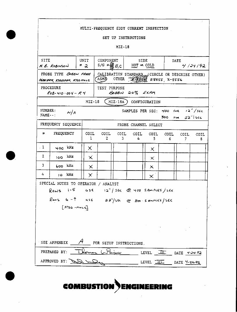
MULTI-FREQUENCY EDDY CURRENT INSPECTION
SET UP INSTRUCTIONS
MIZ-18
SITE UNIT COMPONENT SIDE DATE
/. d. Rodemed # S/G #f HOT - COLD /y / gg
PROBE TYPE 808&e/ AOMd CALIBRATION STANDARD. (CIRCLE OR DESCRIBE OTHER) ,463sfesl .470osAWd, A7aO1ue OTHER.
PROCEDURE TEST PURPOSE
MIZ-18 CONFIGURATION
NUMBER: A 'A SAMPLES PER SEC: '/00 fog 1:1 " /sce NAME--: 00
FREQUENCY SEQUENCE PROBE CHANNEL SELECT
4 FREQUENCY COIL COIL COIL COIL COIL COIL COIL COIL 1 2 3 4 5 6 7 8
% 400 kHz
2 loo kHz
3 ojo kHz X
4 lo kHz x SPECIAL NOTES TO OPERATOR / ANALYST
1OJ -'5~ (ASE i';L" / 5 r <2 '40 S A- 'P L f; 5 E
t,-~ 6 P ~ ~ S &,PLCS/ SEC
SEE APPENDIX 1_ FOR SETUP INSTRUCTIONS.
PREPARED BY: (.- LEVEL Z DATE 9 ,2-91
APPROVED BY: LEVEL 7 DATE 'I-Z.-q.
COMBUTION ENINEERING
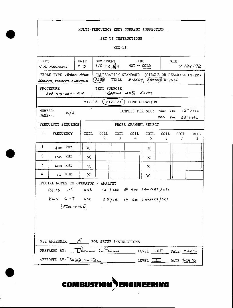
MULTI-FREQUENCY EDDY CURRENT INSPECTION
SET UP INSTRUCTIONS
MIZ-18
SITE UNIT COMPONENT SIDE DATE
//.B. Reodwsejd # a S/G #A gc HOT oA COLD I. / I/9a
PROBE TYPE &886 "odE CALIBRATION STANDARD (CIRCLE OR DESCRIBE OTHER)
4630srM&, .47oostfept, &7ac0rue OTHER j2-.TSy s 2-954
PROCEDURE TEST PURPOSE 0 - 00 a ~~% £E)FA
MIZ-18 CONFIGURATION
NUMBER: SAMPLES PER SEC: -900 feo sEc NAME--: aoo 5ic
FREQUENCY SEQUENCE PROBE CHANNEL SELECT
# FREQUENCY COIL COIL COIL COIL COIL COIL COIL COIL 1 2 3 4 5 6 7 8
.1 L400 kHz
2 100 kHz
3 600kHz
4 ) kHz x
SPECIAL NOTES TO OPERATOR / ANALYST
LA~a -ML~
SEE APPENDIX _ 04 FOR SETUP INSTRUCTIONS.
PREPARED BY: LEVEL DATE + 92
APPROVED BY: LEVEL . 1- DATE 'i-19-9q
OMUTON ENGNEERING
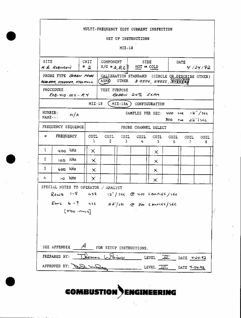
MULTI-FREQUENCY EDDY CURRENT INSPECTION
SET UP INSTRUCTIONS
MIZ-18
SITE UNIT COMPONENT SIDE DATE
//'e. RodwsodJ # S/G #A g) HOT *^ COLD y
PROBE TYPE 8066,j AEO'dE CALIBRATION STANDARD (CIRCLE ORDESCRI BE OTHER) OTHER . -. s9 Esss R67Asme'1, .470OOIP, Aa~~c
PROCEDURE TEST PURPOSE o Do% EA 1
MIZ-18 CONFIGURATION
NUMBER: NIA SAMPLES PER SEC: Aoo foR EQ : "c NAME- -: 00 ai
FREQUENCY SEQUENCE PROBE CHANNEL SELECT
FREQUENCY COIL COIL COIL COIL COIL COIL COIL COIL 1 2 3 4 5 6 7 8
1 t4oo kHz
2 loo kHz
3 bao kHz x
4 to kHz
SPECIAL NOTES TO OPERATOR / ANALYST
~~~~ & ,c.'4u /PLCS SEC
SEE APPENDIX /4 FOR SETUP INSTRUCTIONS.
PREPARED BY: LEVEL -I: DATE sw9
APPROVED BY: LEVEL 'tk DATE 'I-2 REC
......... N ENG IN EER IN G
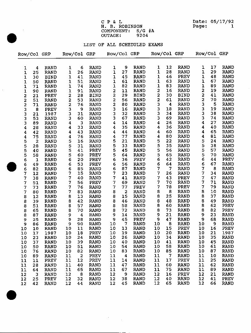
CP & L Date: 05/17/92 H. B. ROBINSON Page: 1 COMPONENT: S/G #A OUTAGE: 9204
LIST OF ALL SCHEDULED EXAMS
Row/Col GRP Row/Col GRP Row/Col GRP Row/Col GRP Row/Col GRP
1 4 RAND 1 6 RAND 1 9 RAND 1 12 RAND 1 17 RAND 1 25 RAND 1 26 RAND 1 27 RAND 1 28 RAND 1 29 RAND 1 30 BIND 1 41 RAND 1 45 RAND 1 46 PREV 1 48 RAND 1 50 RAND 1 51 RAND 1 61 RAND 1 63 RAND 1 67 RAND 1 71 RAND 1 74 RAND 1 82 RAND 1 83 RAND 1 89 RAND 190 RAND 191 RAND 211 RAND 216 RAND 219 RAND 2 21 PREV 2 28 BIND 2 29 BIND 2 30 BIND 2 41 RAND 2 51 RAND 2 53 RAND 2 56 RAND 2 61 RAND 2 70 RAND 2 71 RAND 2 76 RAND 2 80 RAND 3 4 RAND 3 5 RAND 3 8 PREV 3 9 RAND 3 16 RAND 3 18 RAND 3 19 RAND 3211987 331 RAND 332 RAND 334 RAND 338 RAND 3 53 RAND 3 60 RAND 3 67 RAND 3 69 RAND 3 74 RAND 3 89 RAND 4 3 RAND 4 14 RAND 4 26 RAND 4 27 RAND 4 28 RAND 4 33 RAND 4 35 RAND 4 36 RAND 4 40 RAND 4 42 RAND 4 43 RAND 4 44 RAND 4 60 RAND 4 65 RAND 4 75 RAND 4 76 RAND 4 77 RAND 4 80 RAND 4 81 RAND 5 2 RAND 5 16 RAND 5 21 RAND 5 22 RAND 5 24 RAND 5 28 RAND 5 31 RAND 5 33 RAND 5 35 RAND 5 38 RAND 5 40 RAND 5 41 PREV 5 45 RAND 5 56 RAND 5 57 RAND 5 58 RAND 5 60 PREV 5 64 RAND 5 65 RAND 5 70 RAND 6 1 RAND 6 20 PREV 6 36 PREV 6 42 RAND 6 44 PREV . 6 49 RAND 6 53 PREV 6 56 RAND 6 64 RAND 6 67 RAND 6 82 RAND 6 85 RAND 6 87 RAND 7 7 RAND 7 8 RAND 7 12 RAND 7 15 RAND 7 23 RAND 7 26 RAND 7 34 RAND 7 38 RAND 7 40 RAND 7 41 RAND 7 43 PREV 7 47 RAND 7 51 RAND 7 56 PREV 7 69 RAND 7 70 RAND 7 71 RAND 7 73 RAND 7 76 RAND 7 77 PREV 7 78 PREV 7 79 RAND 7 80 RAND 7 83 RAND 8 2 RAND 8 8 RAND 8 10 RAND 8 12 RAND 8 13 RAND 8 15 RAND 8 25 RAND 8 37 RAND 8 39 RAND 8 42 RAND 8 46 RAND 8 48 RAND 8 49 RAND 8 51 RAND 8 57 RAND 8 58 RAND 8 60 RAND 8 62 PREV 8 65 RAND 8 70 RAND 8 72 RAND 8 73 RAND 8 82 PREV 8 87 RAND 9 4 RAND 9 14 RAND 9 21 RAND 9 23 RAND 9 25 RAND 9 28 RAND 9 45 PREV 9 47 RAND 9 68 RAND 9 86 RAND 9 90 RAND 10 7 RAND 10 8 RAND 10 9 RAND
10 10 RAND 10 11 RAND 10 13 RAND 10 15 PREV 10 16 PREV 10 17 1987 10 18 PREV 10 19 RAND 10 20 RAND 10 21 1987 10 23 RAND 10 24 RAND 10 26 RAND 10 34 RAND 10 35 RAND 10 37 RAND 10 39 RAND 10 40 RAND 10 41 RAND 10 45 RAND 10 50 RAND 10 51 RAND 10 54 RAND 10 58 RAND 10 61 RAND 10 76 RAND 10 82 RAND 10 83 RAND 10 85 RAND 10 87 RAND 10 89 RAND 11 2 PREV 11 4 RAND 11 7 RAND 11 10 RAND 11 11 PREV 11 12 PREV 11 14 RAND 11 17 PREV 11 25 RAND 11 28 RAND 11 40 RAND 11 47 RAND 11 60 RAND 11 62 RAND 11 64 RAND 11 65 RAND 11 67 RAND 11 75 RAND 11 89 RAND 12 3 RAND 12 8 RAND 12 9 RAND 12 16 PREV 12 21 RAND 12 25 PREV 12 32 RAND 12 38 RAND 12 40 RAND 12 41 PREV 12 42 RAND 12 44 RAND 12 45 RAND 12 65 RAND 12 66 RAND
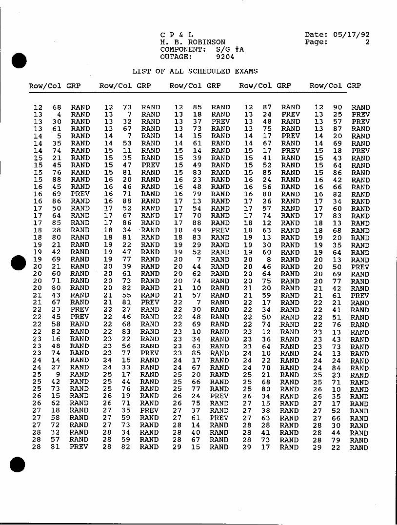
CP & L Date: 05/17/92 H. B. ROBINSON Page: 2 COMPONENT: S/G #A OUTAGE: 9204
LIST OF ALL SCHEDULED EXAMS
Row/Col GRP Row/Col GRP Row/Col GRP Row/Col GRP Row/Col GRP
12 68 RAND 12 73 RAND 12 85 RAND 12 87 RAND 12 90 RAND 13 4 RAND 13 7 RAND 13 18 RAND 13 24 PREV 13 25 PREV 13 30 RAND 13 32 RAND 13 37 PREV 13 48 RAND 13 57 PREV 13 61 RAND 13 67 RAND 13 73 RAND 13 75 RAND 13 87 RAND 14 5 RAND 14 7 RAND 14 15 RAND 14 17 PREV 14 20 RAND 14 35 RAND 14 53 RAND 14 61 RAND 14 67 RAND 14 69 RAND 14 74 RAND 15 11 RAND 15 14 RAND 15 17 PREV 15 18 PREV 15 21 RAND 15 35 RAND 15 39 RAND 15 41 RAND 15 43 RAND 15 45 RAND 15 47 PREV 15 49 RAND 15 52 RAND 15 64 RAND 15 76 RAND 15 81 RAND 15 83 RAND 15 85 RAND 15 86 RAND 15 88 RAND 16 20 RAND 16 23 RAND 16 24 RAND 16 42 RAND 16 45 RAND 16 46 RAND 16 48 RAND 16 56 RAND 16 66 RAND 16 69 PREV 16 71 RAND 16 79 RAND 16 80 RAND 16 82 RAND 16 86 RAND 16 88 RAND 17 13 RAND 17 26 RAND 17 34 RAND 17 50 RAND 17 52 RAND 17 54 RAND 17 57 RAND 17 60 RAND 17 64 RAND 17 67 RAND 17 70 RAND 17 74 RAND 17 83 RAND 17 85 RAND 17 86 RAND 17 88 RAND 18 12 RAND 18 13 RAND 18 28 RAND 18 34 RAND 18 49 PREV 18 63 RAND 18 68 RAND 18 80 RAND 18 81 RAND 18 83 RAND 19 13 RAND 19 20 RAND 19 21 RAND 19 22 RAND 19 29 RAND 19 30 RAND 19 35 RAND 19 42 RAND 19 47 RAND 19 52 RAND 19 60 RAND 19 64 RAND 19 69 RAND 19 77 RAND 20 7 RAND 20 8 RAND 20 13 RAND 20 21 RAND 20 39 RAND 20 44 RAND 20 46 RAND 20 50 PREV 20 60 RAND 20 61 RAND 20 62 RAND 20 64 RAND 20 69 RAND 20 71 RAND 20 73 RAND 20 74 RAND 20 75 RAND 20 77 RAND 20 80 RAND 20 82 RAND 21 10 RAND 21 20 RAND 21 42 RAND 21 43 RAND 21 55 RAND 21 57 RAND 21 59 RAND 21 61 PREV 21 67 RAND 21 81 PREV 22 7 RAND 22 17 RAND 22 21 RAND 22 23 PREV 22 27 RAND 22 30 RAND 22 34 RAND 22 41 RAND 22 45 PREV 22 46 RAND 22 48 RAND 22 50 RAND 22 51 RAND 22 58 RAND 22 68 RAND 22 69 RAND 22 74 RAND 22 76 RAND 22 82 RAND 22 83 RAND 23 10 RAND 23 12 RAND 23 13 RAND 23 16 RAND 23 22 RAND 23 34 RAND 23 36 RAND 23 43 RAND 23 48 RAND 23 56 RAND 23 63 RAND 23 64 RAND 23 73 RAND 23 74 RAND 23 77 PREV 23 85 RAND 24 10 RAND 24 13 RAND 24 14 RAND 24 15 RAND 24 17 RAND 24 22 RAND 24 24 RAND 24 27 RAND 24 33 RAND 24 67 RAND 24 70 RAND 24 84 RAND 25 9 RAND 25 17 RAND 25 20 RAND 25 21 RAND 25 23 RAND 25 42 RAND 25 44 RAND 25 66 RAND 25 68 RAND 25 71 RAND 25 73 RAND 25 76 RAND 25 77 RAND 25 80 RAND 26 10 RAND 26 15 RAND 26 19 RAND 26 24 PREV 26 34 RAND 26 35 RAND 26 62 RAND 26 71 RAND 26 75 RAND 27 15 RAND 27 17 RAND 27 18 RAND 27 35 PREV 27 37 RAND 27 38 RAND 27 52 RAND 27 58 RAND 27 59 RAND 27 61 PREV 27 63 RAND 27 66 RAND 27 72 RAND 27 73 RAND 28 14 RAND 28 28 RAND 28 30 RAND 28 32 RAND 28 34 RAND 28 40 RAND 28 41 RAND 28 44 RAND 28 57 RAND 28 59 RAND 28 67 RAND 28 73 RAND 28 79 RAND 28 81 PREV 28 82 RAND 29 15 RAND 29 17 RAND 29 22 RAND
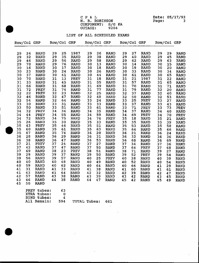
CP & L Date: 05/17/92 H. B. ROBINSON Page: 3 COMPONENT: S/G #A OUTAGE: 9204
LIST OF ALL SCHEDULED EXAMS
Row/Col GRP Row/Col GRP Row/Col GRP Row/Col GRP Row/Col GRP
29 24 RAND 29 25 1987 29 26 RAND 29 27 RAND 29 29 RAND 29 32 RAND 29 35 RAND 29 38 RAND 29 40 RAND 29 45 RAND 29 46 RAND 29 56 RAND 29 58 RAND 29 62 RAND 29 63 RAND 29 70 RAND 29 76 RAND 30 13 RAND 30 14 RAND 30 15 RAND 30 16 RAND 30 17 RAND 30 18 RAND 30 19 RAND 30 20 RAND 30 23 RAND 30 24 RAND 30 26 RAND 30 33 RAND 30 34 RAND 30 37 RAND 30 41 RAND 30 44 RAND 30 61 RAND 30 65 RAND 30 70 RAND 31 13 PREV 31 18 RAND 31 21 1987 31 22 RAND 31 33 RAND 31 45 RAND 31 55 RAND 31 57 RAND 31 65 RAND 31 66 RAND 31 68 RAND 31 69 RAND 31 70 RAND 31 71 RAND 31 72 PREV 31 74 RAND 31 77 RAND 31 79 RAND 32 20 RAND 32 22 PREV 32 23 RAND 32 25 RAND 32 37 RAND 32 40 RAND 32 46 RAND 32 47 RAND 32 48 RAND 32 50 RAND 32 53 RAND 32 54 RAND 32 64 RAND 33 24 RAND 33 25 PREV 33 27 RAND 33 30 RAND 33 31 RAND 33 33 RAND 33 37 RAND 33 43 RAND 33 50 RAND 33 51 RAND 33 61 RAND 33 71 PREV 33 73 PREV 34 32 PREV 34 34 RAND 34 35 RAND 34 37 RAND 34 40 RAND 34 44 PREV 34 55 RAND 34 59 RAND 34 69 PREV 34 70 PREV 34 72 RAND 34 75 RAND 34 76 PREV 35 18 RAND 35 21 RAND 35 26 RAND 35 30 RAND 35 33 RAND 35 35 RAND 35 39 RAND 35 43 PREV 35 46 RAND 35 51 RAND 35 53 RAND 35 58 RAND 35 60 RAND 35 61 RAND 35 63 RAND 35 64 RAND 35 66 RAND 35 67 RAND 35 74 RAND 36 20 RAND 36 21 RAND 36 24 RAND 36 28 RAND 36 29 RAND 36 31 RAND 36 32 RAND 36 36 RAND 36 38 RAND 36 47 RAND 36 53 RAND 36 68 RAND 36 69 RAND 37 21 PREV 37 24 RAND 37 27 RAND 37 34 RAND 37 36 RAND 37 42 RAND 37 47 RAND 37 55 RAND 37 64 PREV 37 68 RAND 37 69 RAND 38 23 PREV 38 51 RAND 38 71 RAND 39 27 RAND 39 29 RAND 39 37 RAND 39 50 RAND 39 52 PREV 39 54 RAND 39 56 RAND 39 57 RAND 40 25 PREV 40 28 RAND 40 39 RAND 40 40 RAND 40 48 RAND 40 49 RAND 40 52 RAND 40 54 RAND 40 59 RAND 40 62 RAND 40 64 RAND 40 66 RAND 41 29 RAND 41 31 RAND 41 33 RAND 41 38 RAND 41 60 RAND 41 61 RAND 41 63 RAND 41 64 RAND 42 32 RAND 42 39 RAND 42 47 RAND 42 57 RAND 43 38 RAND 43 39 RAND 43 42 RAND 43 45 RAND 43 46 RAND 44 38 RAND 44 47 RAND 45 42 RAND 45 49 RAND 45 50 RAND
PREV tubes: 63 XTRA tubes: 0 BIND tubes: 4 All Remain: 594 TOTAL Tubes: 661
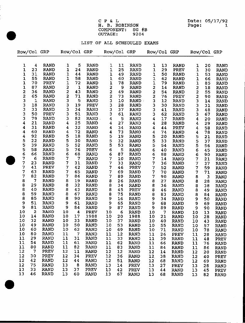
CP & L Date: 05/17/92 H. B. ROBINSON Page: 1 COMPONENT: SG #B OUTAGE: 9204
LIST OF ALL SCHEDULED EXAMS
Row/Col GRP Row/Col GRP Row/Col GRP Row/Col GRP Row/Col GRP
1 4 RAND 1 5 RAND 1 11 RAND 1 13 RAND 1 20 RAND 1 23 RAND 1 24 RAND 1 25 RAND 1 29 PREV 1 30 RAND 1 31 RAND 1 44 RAND 1 49 RAND 1 50 RAND 1 53 RAND 1 55 RAND 1 58 RAND 1 60 RAND 1 62 RAND 1 66 RAND 1 70 PREV 1 72 RAND 1 78 RAND 1 79 RAND 1 85 RAND 1 87 RAND 2 1 RAND 2 9 RAND 2 14 RAND 2 18 RAND 2 36 RAND 2 43 RAND 2 49 RAND 2 54 RAND 2 55 RAND 2 65 RAND 2 71 RAND 2 73 RAND 2 76 PREV 2 90 RAND 3 1 RAND 3 5 RAND 3 10 RAND 3 12 RAND 3 14 RAND 3 18 RAND 3 19 PREV 3 28 RAND 3 30 RAND 3 31 RAND 3 33 RAND 3 34 RAND 3 37 RAND 3 41 RAND 3 48 RAND 3 50 PREV 3 51 RAND 3 61 RAND 3 62 RAND 3 67 RAND 3 79 RAND 3 82 RAND. 4 5 RAND 4 17 RAND 4 20 RAND 4 21 RAND 4 25 RAND 4 27 RAND 4 28 RAND 4 29 RAND 4 31 RAND 4 32 RAND 4 34 RAND 4 44 PREV 4 58 RAND 4 60 RAND 4 72 RAND 4 73 RAND 4 74 RAND 4 78 RAND 4 92 RAND 5 18 RAND 5 19 RAND 5 20 RAND 5 21 RAND 5 22 RAND 5 30 RAND 5 32 RAND 5 33 RAND 5 37 RAND 5 39 RAND 5 52 RAND 5 53 RAND 5 54 RAND 5 56 RAND 5 58 RAND 5 76 PREV 6 5 RAND 6 40 RAND 6 45 RAND 6 66 RAND 6 68 RAND 6 87 RAND 6 88 RAND 6 90 RAND . 7 6 RAND 7 7 RAND 7 10 RAND 7 14 RAND 7 21 RAND 7 23 RAND 7 31 RAND 7 33 RAND 7 36 RAND 7 37 RAND 7 41 PREV 7 42 RAND 7 46 PREV 7 52 RAND 7 59 RAND 7 63 RAND 7 65 RAND 7 69 RAND 7 70 RAND 7 71 RAND 7 82 RAND 7 86 RAND 7 89 RAND 7 90 RAND 8 3 RAND 8 7 RAND 8 19 RAND 8 26 RAND 8 27 RAND 8 28 RAND 8 29 RAND 8 32 RAND 8 34 RAND 8 36 RAND 8 38 RAND 8 40 RAND 8 43 RAND 8 45 PREV 8 46 RAND 8 49 RAND 8 59 RAND 8 67 RAND 8 75 RAND 8 83 RAND 8 84 RAND 8 85 RAND 8 90 RAND 9 16 RAND 9 34 RAND 9 50 RAND 9 51 RAND 9 61 RAND 9 65 RAND 9 68 RAND 9 69 RAND 9 81 RAND 9 84 RAND 9 87 RAND 9 89 RAND 9 90 RAND
10 2 RAND 10 4 PREV 10 6 RAND 10 7 RAND 10 13 RAND 10 14 RAND 10 17 1988 10 20 1988 10 21 RAND 10 28 RAND 10 32 RAND 10 33 RAND 10 37 RAND 10 40 RAND 10 43 RAND 10 49 RAND 10 50 RAND 10 53 RAND 10 55 RAND 10 57 RAND 10 60 RAND 10 62 RAND 10 69 RAND 10 71 RAND 10 78 RAND 10 80 RAND 11 7 RAND 11 12 RAND 11 26 PREV 11 28 RAND 11 29 RAND 11 31 RAND 11 33 RAND 11 39 RAND 11 48 PREV 11 54 RAND 11 61 RAND 11 62 RAND 11 66 RAND 11 76 RAND 11 80 RAND 11 82 RAND 11 83 RAND 11 84 RAND 11 86 RAND 12 7 PREV 12 11 RAND 12 12 RAND 12 14 RAND 12 20 RAND 12 30 PREV 12 34 PREV 12 36 RAND 12, 38 RAND 12 40 PREV 12 42 RAND 12 44 RAND 12 51 RAND 12 68 RAND 12 69 RAND 12 75 RAND 13 8 RAND 13 14 PREV 13 27 PREV 13 28 RAND 13 33 RAND 13 37 PREV 13 42 PREV 13 44 RAND 13 45 PREV 13 46 RAND 13 60 RAND 13 67 RAND 13 68 RAND 13 82 RAND
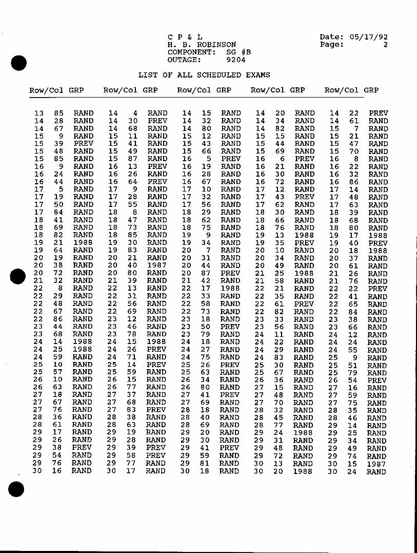
CP & L Date: 05/17/92 H. B. ROBINSON Page: 2 COMPONENT: SG #B OUTAGE: 9204
LIST OF ALL SCHEDULED EXAMS
Row/Col GRP Row/Col GRP Row/Col GRP Row/Col GRP Row/Col GRP
13 85 RAND 14 4 RAND 14 15 RAND 14 20 RAND 14 22 PREV 14 28 RAND 14 30 PREV 14 32 RAND 14 34 RAND 14 61 RAND 14 67 RAND 14 68 RAND 14 80 RAND 14 82 RAND 15 7 RAND 15 9 RAND 15 11 RAND 15 12 RAND 15 15 RAND 15 21 RAND 15 39 PREV 15 41 RAND 15 43 RAND 15 44 RAND 15 47 RAND 15 48 RAND 15 49 RAND 15 66 RAND 15 69 RAND 15 70 RAND 15 85 RAND 15 87 RAND 16 5 PREV 16 6 PREV 16 8 RAND 16 9 RAND 16 13 PREV 16 19 RAND 16 21 RAND 16 22 RAND 16 24 RAND 16 26 RAND 16 28 RAND 16 30 RAND 16 32 RAND 16 44 RAND 16 64 PREV 16 67 RAND 16 72 RAND 16 86 RAND 17 5 RAND 17 9 RAND 17 10 RAND 17 12 RAND 17 14 RAND 17 19 RAND 17 28 RAND 17 32 RAND 17 43 PREV 17 48 RAND 17 50 RAND 17 55 RAND 17 56 RAND 17 62 RAND 17 63 RAND 17 84 RAND 18 8 RAND 18 29 RAND 18 30 RAND 18 39 RAND 18 41 RAND 18 47 RAND 18 62 RAND 18 66 RAND 18 68 RAND 18 69 RAND 18 73 RAND 18 75 RAND 18 76 RAND 18 80 RAND 18 82 RAND 18 85 RAND 19 9 RAND 19 13 1988 19 17 1988 19 21 1988 19 30 RAND 19 34 RAND 19 35 PREV 19 40 PREV 19 64 RAND 19 83 RAND 20 7 RAND 20 10 RAND 20 18 1988 20 19 RAND 20 21 RAND 20 31 RAND 20 34 RAND 20 37 RAND 20 38 RAND 20 40 1987 20 44 RAND 20 49 RAND 20 61 RAND 20 72 RAND 20 80 RAND 20 87 PREV 21 25 1988 21 26 RAND 21 32 RAND 21 39 RAND 21 42 RAND 21 58 RAND 21 76 RAND 22 8 RAND 22 13 RAND 22 17 1988 22 21 RAND 22 22 PREV 22 29 RAND 22 31 RAND 22 33 RAND 22 35 RAND 22 41 RAND 22 48 RAND 22 56 RAND 22 58 RAND 22 61 PREV 22 65 RAND 22 67 RAND 22 69 RAND 22 73 RAND 22 82 RAND 22 84 RAND 22 86 RAND 23 12 RAND 23 18 RAND 23 33 RAND 23 38. RAND 23 44 RAND 23 46 RAND 23 50 PREV 23 56 RAND 23 66 RAND 23 68 RAND 23 78 RAND 23 79 RAND 24 11 RAND 24 12 RAND 24 14 1988 24 15 1988 24 18 RAND 24 22 RAND 24 24 RAND 24 25 1988 24 26 PREV 24 27 RAND 24 29 RAND 24 55 RAND 24 59 RAND 24 71 RAND 24 75 RAND 24 83 RAND 25 9 RAND 25 10 RAND 25 14 PREV 25 26 PREV 25 30 RAND 25 51 RAND 25 57 RAND 25 59 RAND 25 63 RAND 25 67 RAND 25 79 RAND 26 10 RAND 26 15 RAND 26 34 RAND 26 36 RAND 26 54 PREV 26 63 RAND 26 77 RAND 26 80 RAND 27 15 RAND 27 16 RAND 27 18 RAND 27 37 RAND 27 41 PREV 27 48 RAND 27 59 RAND 27 67 RAND 27 68 RAND 27 69 RAND 27 70 RAND 27 75 RAND 27 76 RAND 27 83 PREV 28 18 RAND 28 32 RAND 28 35 RAND 28 36 RAND 28 38 RAND 28 40 RAND 28 45 RAND 28 46 RAND 28 61 RAND 28 63 RAND 28 69 RAND 28 77 RAND 29 14 RAND 29 17 RAND 29 19 RAND 29 20 RAND 29 24 1988 29 25 RAND 29 26 RAND 29 28 RAND 29 30 RAND 29 31 RAND 29 34 RAND 29 38 PREV 29 39 PREV 29 41 PREV 29 48 RAND 29 49 RAND 29 54 RAND 29 58 PREV 29 59 RAND 29 72 RAND 29 74 RAND 29 76 RAND 29 77 RAND 29 81 RAND 30 13 RAND 30 15 1987 30 16 RAND 30 17 RAND 30 18 RAND 30 20 1988 30 24 RAND
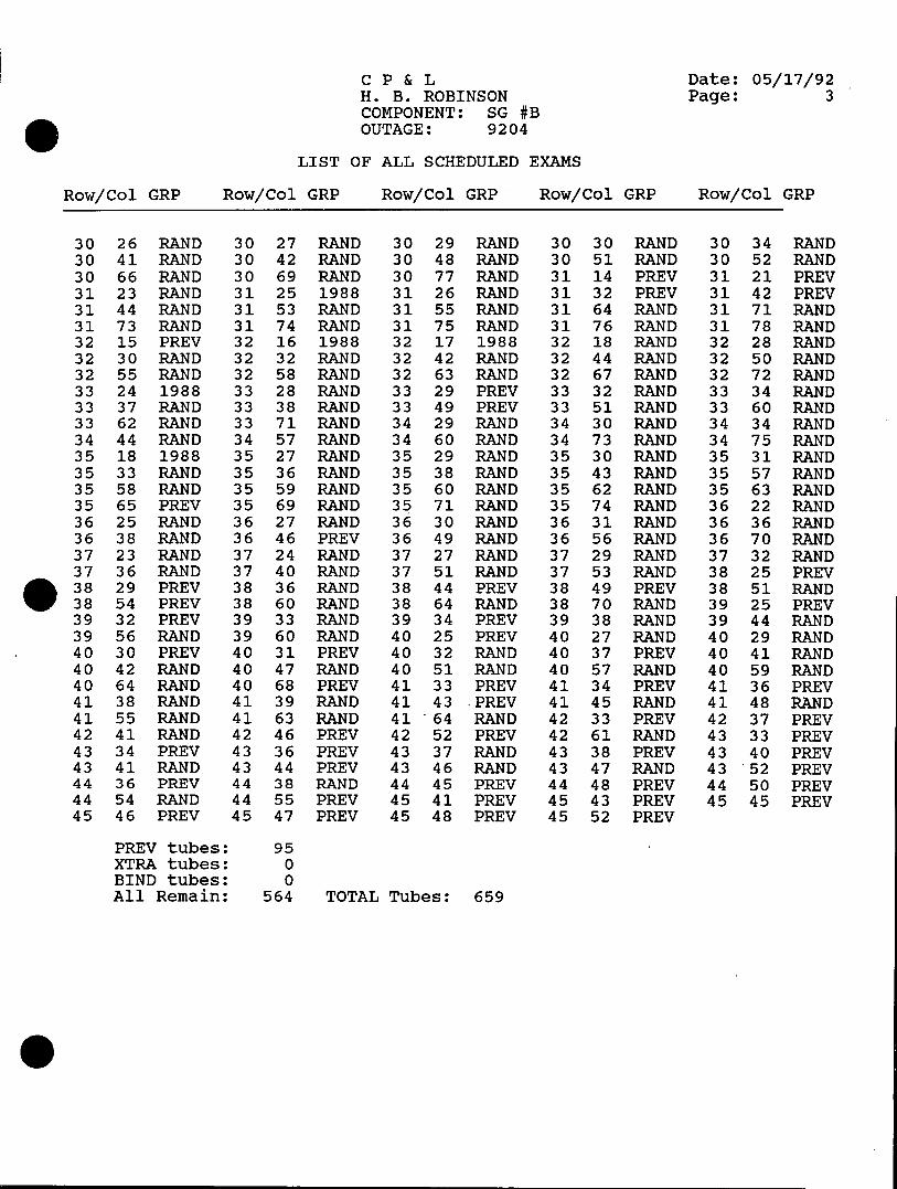
CP & L Date: 05/17/92 H. B. ROBINSON Page: 3 COMPONENT: SG #B OUTAGE: 9204
LIST OF ALL SCHEDULED EXAMS
Row/Col GRP Row/Col GRP Row/Col GRP Row/Col GRP Row/Col GRP
30 26 RAND 30 27 RAND 30 29 RAND 30 30 RAND 30 34 RAND 30 41 RAND 30 42 RAND 30 48 RAND 30 51 RAND 30 52 RAND 30 66 RAND 30 69 RAND 30 77 RAND 31 14 PREV 31 21 PREV 31 23 RAND 31 25 1988 31 26 RAND 31 32 PREV 31 42 PREV 31 44 RAND 31 53 RAND 31 55 RAND 31 64 RAND 31 71 RAND 31 73 RAND 31 74 RAND 31 75 RAND 31 76 RAND 31 78 RAND 32 15 PREV 32 16 1988 32 17 1988 32 18 RAND 32 28 RAND 32 30 RAND 32 32 RAND 32 42 RAND 32 44 RAND 32 50 RAND 32 55 RAND 32 58 RAND 32 63 RAND 32 67 RAND 32 72 RAND 33 24 1988 33 28 RAND 33 29 PREV 33 32 RAND 33 34 RAND 33 37 RAND 33 38 RAND 33 49 PREV 33 51 RAND 33 60 RAND 33 62 RAND 33 71 RAND 34 29 RAND 34 30 RAND 34 34 RAND 34 44 RAND 34 57 RAND 34 60 RAND 34 73 RAND 34 75 RAND 35 18 1988 35 27 RAND 35 29 RAND 35 30 RAND 35 31 RAND 35 33 RAND 35 36 RAND 35 38 RAND 35 43 RAND 35 57 RAND 35 58 RAND 35 59 RAND 35 60 RAND 35 62 RAND 35 63 RAND 35 65 PREV 35 69 RAND 35 71 RAND 35 74 RAND 36 22 RAND 36 25 RAND 36 27 RAND 36 30 RAND 36 31 RAND 36 36 RAND 36 38 RAND 36 46 PREV 36 49 RAND 36 56 RAND 36 70 RAND 37 23 RAND 37 24 RAND 37 27 RAND 37 29 RAND 37 32 RAND 37 36 RAND 37 40 RAND 37 51 RAND 37 53 RAND 38 25 PREV 38 29 PREV 38 36 RAND 38 44 PREV 38 49 PREV 38 51 RAND 38 54 PREV 38 60 RAND 38 64 RAND 38 70 RAND 39 25 PREV 39 32 PREV 39 33 RAND 39 34 PREV 39 38 RAND 39 44 RAND 39 56 RAND 39 60 RAND 40 25 PREV 40 27 RAND 40 29 RAND 40 30 PREV 40 31 PREV 40 32 RAND 40 37 PREV 40 41 RAND 40 42 RAND 40 47 RAND 40 51 RAND 40 57 RAND 40 59 RAND 40 64 RAND 40 68 PREV 41 33 PREV 41 34 PREV 41 36 PREV 41 38 RAND 41 39 RAND 41 43 .PREV 41 45 RAND 41 48 RAND 41 55 RAND 41 63 RAND 41 64 RAND 42 33 PREV 42 37 PREV 42 41 RAND 42 46 PREV 42 52 PREV 42 61 RAND 43 33 PREV 43 34 PREV 43 36 PREV 43 37 RAND 43 38 PREV 43 40 PREV 43 41 RAND 43 44 PREV 43 46 RAND 43 47 RAND 43 52 PREV 44 36 PREV 44 38 RAND 44 45 PREV 44 48 PREV 44 50 PREV 44 54 RAND 44 55 PREV 45 41 PREV 45 43 PREV 45 45 PREV 45 46 PREV 45 47 PREV 45 48 PREV 45 52 PREV
PREV tubes: 95 XTRA tubes: 0 BIND tubes: 0 All Remain: 564 TOTAL Tubes: 659

CP & L Date: 05/17/92 H. B. ROBINSON Page: 1 COMPONENT: SG #C OUTAGE: 9204
LIST OF ALL SCHEDULED EXAMS
Row/Col GRP Row/Col GRP Row/Col GRP Row/Col GRP Row/Col GRP
1 4 RAND 1 6 RAND 1 7 RAND 1 8 RAND 1 9 RAND 1 11 RAND 1 12 RAND 1 16 RAND 1 34 RAND 1 35 RAND 1 43 RAND 1 44 RAND 1 47 RAND 1 55 RAND 1 56 RAND 1 57 RAND 1 74 RAND 1 79 PREV 1 83 RAND 1 84 RAND 1 87 RAND 2 1 RAND 2 3 RAND 2 11 RAND 2 13 RAND 216 RAND 224 RAND 226 RAND 227 RAND 231 RAND 2 32 RAND 2 38 RAND 2 39 RAND 2 40 RAND 2 46 RAND 2 48 RAND 2 50 RAND 2 53 RAND 2 57 RAND 2 59 RAND 2 65 RAND 2 69 RAND 2 70 RAND 2 73 RAND 2 75 RAND 2 81 RAND 2 82 RAND 2 84 PREV 3 1 RAND 3 4 PREV 3 5 PREV 3 18 RAND 3 20 RAND 3 24 RAND 3 26 RAND 3 34 RAND 3 41 RAND 3 43 PREV 3 44 RAND 3 46 RAND 3 48 RAND 3 52 RAND 3 53 RAND 3 58 RAND 3 62 RAND 3 66 RAND 3 69 RAND 3 74 RAND 3 75 RAND 3 77 RAND 3 80 RAND 3 88 RAND 4 6 PREV 4 10 RAND 4 14 RAND 4 22 RAND 4 23 RAND 4 24 RAND 4 26 RAND 4 35 RAND 4 37 RAND 4 45 RAND 4 62 RAND 4 75 RAND 4 76 RAND 4 78 PREV 4 81 RAND 4 82 RAND 4 83 RAND 4 85 RAND 4 89 RAND 5 8 RAND 5 9 RAND 5 13 PREV 5 23 RAND 5 24 RAND 5 25 RAND 5 43 RAND 5 46 RAND 5 51 RAND 5 56 RAND 5 62 RAND 5 64 RAND 5 66 PREV 5 68 RAND . 5 69 RAND 5 89 RAND 5 91 RAND 6 1 RAND 6 3 PREV 6 30 PREV 6 35 PREV 6 41 RAND 6 42 RAND 6 45 RAND 6 46 RAND 6 47 RAND 6 54 RAND 6 61 PREV 6 64 RAND 6 73 RAND 6 75 PREV 6 89 RAND 6 90 RAND 7 3 PREV 7 6 RAND 7 8 RAND 7 9 RAND 7 19 RAND 7 26 RAND 7 37 RAND 7 44 RAND 7 49 RAND 7 50 PREV 7 56 RAND 7 60 PREV 7 63 RAND 7 69 PREV 7 70 RAND 7 71 RAND 784 RAND 789 RAND 8 3 RAND 8 4 RAND 8 7 RAND 8 12 RAND 8 15 RAND 8 22 RAND 8 23 RAND 8 26 RAND 8 30 PREV 8 31 RAND 8 36 RAND 8 39 RAND 8 61 PREV 8 63 RAND 8 65 RAND 8 68 PREV 8 73 PREV 8 79 RAND 8 89 RAND 8 90 RAND 9 4 RAND 9 15 RAND 9 30 RAND 9 38 RAND 9 42 RAND 9 50 PREV 9 59 RAND 9 62 RAND 9 64 PREV 9 66 RAND 9 67 RAND 9 70 RAND 9 86 RAND 9 88 RAND 9 90 RAND 10 2 RAND 10 3 RAND 10 4 RAND
10 6 RAND 10 8 RAND 10 10 RAND 10 11 RAND 10 18 RAND 10 19 RAND 10 21 RAND 10 25 PREV 10 27 RAND 10 29 RAND 10 31 RAND 10 34 RAND 10 51 RAND 10 53 RAND 10 54 RAND 10 55 PREV 10 56 RAND 10 57 RAND 10 72 RAND 10 78 RAND 10 80 RAND 10 83 RAND 10 87 RAND 11 7 RAND 11 8 RAND 11 12 RAND 11 18 RAND 11 23 PREV 11 24 PREV 11 26 RAND 11 27 RAND 11 31 RAND 11 35 RAND 11 42 PREV 11 56 RAND 11 68 RAND 11 70 RAND 11 72 RAND 11 73 RAND 11 75 RAND 11 78 RAND 11 79 RAND 11 80 RAND 11 81 RAND 11 82 RAND 11 83 RAND 12 3 RAND 12 6 RAND 12 8 RAND 12 12 RAND 12 14 RAND 12 19 PREV 12 21 RAND 12 27 RAND 12 38 RAND 12 41 RAND 12 47 RAND 12 51 RAND 12 58 RAND 12 62 RAND
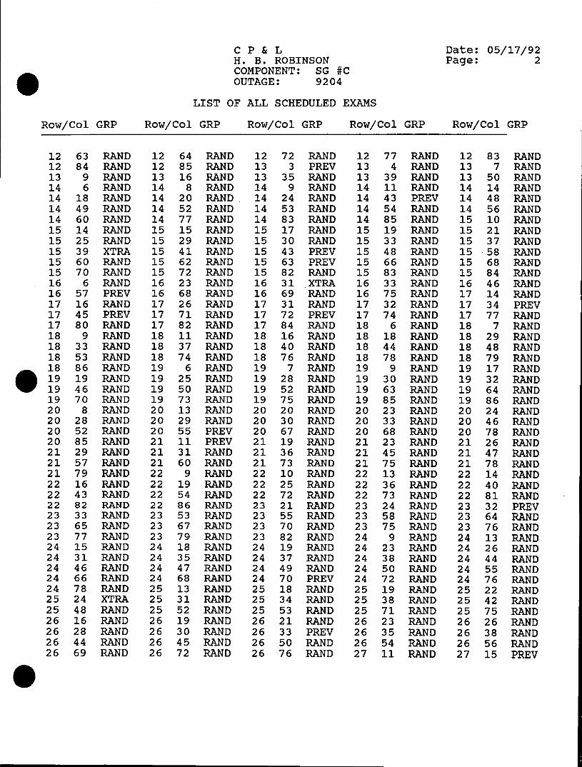
CP & L Date: 05/17/92 H. B. ROBINSON Page: 2 COMPONENT: SG #C OUTAGE: 9204
LIST OF ALL SCHEDULED EXAMS
Row/Col GRP Row/Col GRP Row/Col GRP Row/Col GRP Row/Col GRP
12 63 RAND 12 64 RAND 12 72 RAND 12 77 RAND 12 83 RAND 12 84 RAND 12 85 RAND 13 3 PREV 13 4 RAND 13 7 RAND 13 9 RAND 13 16 RAND 13 35 RAND 13 39 RAND 13 50 RAND 14 6 RAND 14 8 RAND 14 9 RAND 14 11 RAND 14 14 RAND 14 18 RAND 14 20 RAND 14 24 RAND 14 43 PREV 14 48 RAND 14 49 RAND 14 52 RAND 14 53 RAND 14 54 RAND 14 56 RAND 14 60 RAND 14 77 RAND 14 83 RAND 14 85 RAND 15 10 RAND 15 14 RAND 15 15 RAND 15 17 RAND 15 19 RAND 15 21 RAND 15 25 RAND 15 29 RAND 15 30 RAND 15 33 RAND 15 37 RAND 15 39 XTRA 15 41 RAND 15 43 PREV 15 48 RAND 15 .58 RAND 15 60 RAND 15 62 RAND 15 63 PREV 15 66 RAND 15 68 RAND 15 70 RAND 15 72 RAND 15 82 RAND 15 83 RAND 15 84 RAND 16 6 RAND 16 23 RAND 16 31 XTRA 16 33 RAND 16 46 RAND 16 57 PREV 16 68 RAND 16 69 RAND 16 75 RAND 17 14 RAND 17 16 RAND 17 26 RAND 17 31 RAND 17 32 RAND 17 34 PREV 17 45 PREV 17 71 RAND 17 72 PREV 17 74 RAND 17 77 RAND 17 80 RAND 17 82 RAND 17 84 RAND 18 6 RAND 18 7 RAND 18 9 RAND 18 11 RAND 18 16 RAND 18 18 RAND 18 29 RAND 18 33 RAND 18 37 RAND 18 40 RAND 18 44 RAND 18 48 RAND 18 53 RAND 18 74 RAND 18 76 RAND 18 78 RAND 18 79 RAND 18 86 RAND 19 6 RAND 19 7 RAND 19 9 RAND 19 17 RAND 19 19 RAND 19 25 RAND 19 28 RAND 19 30 RAND 19 32 RAND 19 46 RAND 19 50 RAND 19 52 RAND 19 63 RAND 19 64 RAND 19 70 RAND 19 73 RAND 19 75 RAND 19 85 RAND 19 86 RAND 20 8 RAND 20 13 RAND 20 20 RAND 20 23 RAND 20 24 RAND 20 28 RAND 20 29 RAND 20 30 RAND 20 33 RAND 20 46 RAND 20 52 RAND 20 55 PREV 20 67 RAND 20 68 RAND 20 78 RAND 20 85 RAND 21 11 PREV 21 19 RAND 21 23 RAND 21 26 RAND 21 29 RAND 21 31 RAND 21 36 RAND 21 45 RAND 21 47 RAND 21 57 RAND 21 60 RAND 21 73 RAND 21 75 RAND 21 78 RAND 21 79 RAND 22 9 RAND 22 10 RAND 22 13 RAND 22 14 RAND 22 16 RAND 22 19 RAND 22 25 RAND 22 36 RAND 22 40 RAND 22 43 RAND 22 54 RAND 22 72 RAND 22 73 RAND 22 81 RAND 22 82 RAND 22 86 RAND 23 21 RAND 23 24 RAND 23 32 PREV 23 33 RAND 23 53 RAND 23 55 RAND 23 58 RAND 23 64 RAND 23 65 RAND 23 67 RAND 23 70 RAND 23 75 RAND 23 76 RAND 23 77 RAND 23 79 RAND 23 82 RAND 24 9 RAND 24 13 RAND 24 15 RAND 24 18 RAND 24 19 RAND 24 23 RAND 24 26 RAND 24 31 RAND 24 35 RAND 24 37 RAND 24 38 RAND 24 44 RAND 24 46 RAND 24 47 RAND 24 49 RAND 24 50 RAND 24 55 RAND 24 66 RAND 24 68 RAND 24 70 PREV 24 72 RAND 24 76 RAND 24 78 RAND 25 13 RAND 25 18 RAND 25 19 RAND 25 22 RAND 25 24 XTRA 25 31 RAND 25 34 RAND 25 38 RAND 25 42 RAND 25 48 RAND 25 52 RAND 25 53 RAND 25 71 RAND 25 75 RAND 26 16 RAND 26 19 RAND 26 21 RAND 26 23 RAND 26 26 RAND 26 28 RAND 26 30 RAND 26 33 PREV 26 35 RAND 26 38 RAND 26 44 RAND 26 45 RAND 26 50 RAND 26 54 RAND 26 56 RAND 26 69 RAND 26 72 RAND 26 76 RAND 27 11 RAND 27 15 PREV
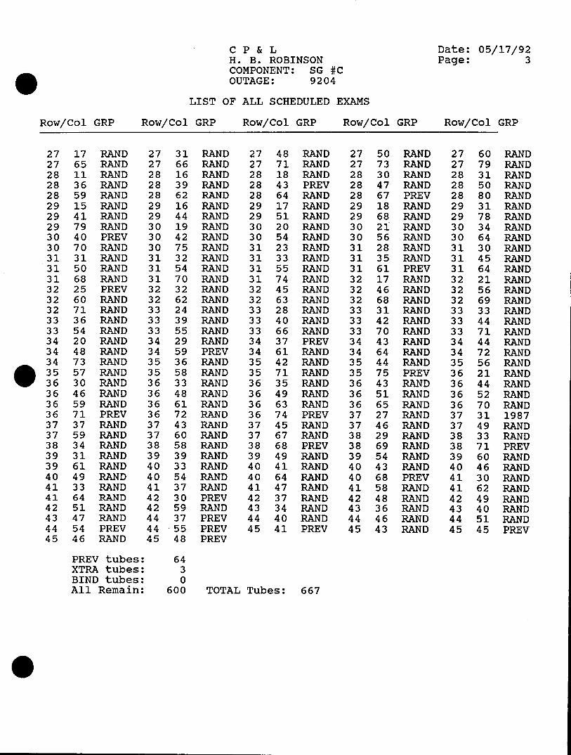
CP & L Date: 05/17/92 H. B. ROBINSON Page: 3 COMPONENT: SG #C OUTAGE: 9204
LIST OF ALL SCHEDULED EXAMS
Row/Col GRP Row/Col GRP Row/Col GRP Row/Col GRP Row/Col GRP
27 17 RAND 27 31 RAND 27 48 RAND 27 50 RAND 27 60 RAND 27 65 RAND 27 66 RAND 27 71 RAND 27 73 RAND 27 79 RAND 28 11 RAND 28 16 RAND 28 18 RAND 28 30 RAND 28 31 RAND 28 36 RAND 28 39 RAND 28 43 PREV 28 47 RAND 28 50 RAND 28 59 RAND 28 62 RAND 28 64 RAND 28 67 PREV 28 80 RAND 29 15 RAND 29 16 RAND 29 17 RAND 29 18 RAND 29 31 RAND 29 41 RAND 29 44 RAND 29 51 RAND 29 68 RAND 29 78 RAND 29 79 RAND 30 19 RAND 30 20 RAND 30 21 RAND 30 34 RAND 30 40 PREV 30 42 RAND 30 54 RAND 30 56 RAND 30 64 RAND 30 70 RAND 30 75 RAND 31 23 RAND 31 28 RAND 31 30 RAND 31 31 RAND 31 32 RAND 31 33 RAND 31 35 RAND 31 45 RAND 31 50 RAND 31 54 RAND 31 55 RAND 31 61 PREV 31 64 RAND 31 68 RAND 31 70 RAND 31 74 RAND 32 17 RAND 32 21 RAND 32 25 PREV 32 32 RAND 32 45 RAND 32 46 RAND 32 56 RAND 32 60 RAND 32 62 RAND 32 63 RAND 32 68 RAND 32 69 RAND 32 71 RAND 33 24 RAND 33 28 RAND 33 31 RAND 33 33 RAND 33 36 RAND 33 39 RAND 33 40 RAND 33 42 RAND 33 44 RAND 33 54 RAND 33 55 RAND 33 66 RAND 33 70 RAND 33 71 RAND 34 20 RAND 34 29 RAND 34 37 PREV 34 43 RAND 34 44 RAND 34 48 RAND 34 59 PREV 34 61 RAND 34 64 RAND 34 72 RAND 34 73 RAND 35 36 RAND 35 42 RAND 35 44 RAND 35 56 RAND 35 57 RAND 35 58 RAND 35 71 RAND 35 75 PREV 36 21 RAND 36 30 RAND 36 33 RAND 36 35 RAND 36 43 RAND 36 44 RAND 36 46 RAND 36 48 RAND 36 49 RAND 36 51 RAND 36 52 RAND 36 59 RAND 36 61 RAND 36 63 RAND 36 65 RAND 36 70 RAND 36 71 PREV 36 72 RAND 36 74 PREV 37 27 RAND 37 31 1987 37 37 RAND 37 43 RAND 37 45 RAND 37 46 RAND 37 49 RAND 37 59 RAND 37 60 RAND 37 67 RAND 38 29 RAND 38 33 RAND 38 34 RAND 38 58 RAND 38 68 PREV 38 69 RAND 38 71 PREV 39 31 RAND 39 39 RAND 39 49 RAND 39 54 RAND 39 60 RAND 39 61 RAND 40 33 RAND 40 41 RAND 40 43 RAND 40 46 RAND 40 49 RAND 40 54 RAND 40 64 RAND 40 68 PREV 41 30 RAND 41 33 RAND 41 37 RAND 41 47 RAND 41 58 RAND 41 62 RAND 41 64 RAND 42 30 PREV 42 37 RAND 42 48 RAND 42 49 RAND 42 51 RAND 42 59 RAND 43 34 RAND 43 36 RAND 43 40 RAND 43 47 RAND 44 37 PREV 44 40 RAND 44 46 RAND 44 51 RAND 44 54 PREV 44 55 PREV 45 41 PREV 45 43 RAND 45 45 PREV 45 46 RAND 45 48 PREV
PREV tubes: 64 XTRA tubes: 3 BIND tubes: 0 All Remain: 600 TOTAL Tubes: 667
0I
CAROLINA POWER AND LIGHT COMPANY H.B. ROBINSON SEG PLANT
SPECIAL PROCEDURE
SP-1110
EDDY CURRENT EXAMINATION OF NONFERROMAGNETIC STEAM GENERATOR TUBING USING MIZ-18 EQUIPMENT
REVISION 0 CONTROLLED RECIPIENT ID. 3%
Effective Date
Expiration Date ________
RECOMMENDED BY: ___________________ -2-9Z.
Supervisor - Technical Support Date
APPROVED BY: I ,/ 1 Manager - Tecnical Support Dave
SP-1110 REV 0 PAGE 1 of 31
LIST OF EFFECTIVE PAGES
EFFECTIVE PAGES REVISION
Cover Sheet 0
LEP 0
3 through 31 0
SP- 1110 REV 0 PAGE 2 of 31

TABLE OF CONTENTS
SECTION 7TLE
1.0 Prerequisites
2.0 Precautions
3.0 Attachment
3.1 Eddy Current Examination of Nonferromagnetic Steam Generator Tubing Using MIZ-18 Equipment
4.0 Disposition of Records
S?-1110 REV 0 PAGE 3 of 31
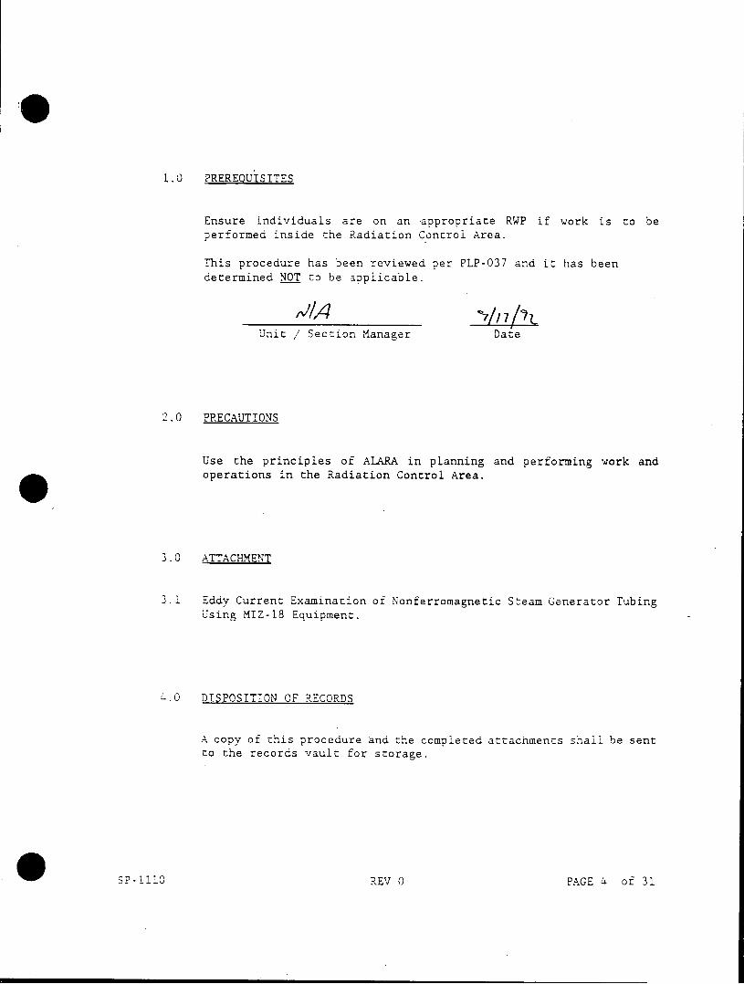
1.0 PREREQUISITES
Ensure individuals are on an -appropriate RWP if work is to be performed inside the Radiation Control Area.
This procedure has been reviewed per PLP-037 and it has been determined NOT to be applicable.
Unit / Section Manager Date
2.0 PRECAUTIONS
Use the principles of ALARA in planning and performing work and * operations in the Radiation Control Area.
3.0 ATTACHMENT
3.1 Eddy Current Examination of Nonferromagnetic Steam Generator Tubing Using MIZ-18 Equipment.
.0 DISPOSITION OF RECORDS
A copy of this procedure and the completed attachments shall be sent to the records vault for storage.
SP-1110 REV 0 PAGE 4 of 31
/-I 7ACj ,re- 3/
Page 1 OF 27
EDDY CURRENT EXAMINATION OF NONFERROMAGNETIC STEAM GENERATOR TUBING USING MIZ-18 EQUIPMENT
H.B. ROBINSON
UNIT 2
PROCEDURE NO.
ROB-410-004
REVISION 4
ABB COMBUSTION ENGINEERING NUCLEAR SERVICES
APPROVED BY: DATE: 3i-?E.T. LEVELI
APPROVED BY DATE: i3 QUALITY 2PERIONS
APPROVED BY: ar DATE: COGNIZANT SUPERVISOR
PROCEDURE NO.: ROB-410-004 REVISION NO.: 4 PAGE NO.: 2 OF 27
TABLE OF CONTENTS
SECTION TITLE
1.0 OBJECTIVE
2.0 SCOPE
3.0 REFERENCES
4.0 PERSONNEL REQUIREMENTS
5.0 PRECAUTIONS AND PREREQUISITES
6.0 CAUBRATION STANDARDS
7.0 EQUIPMENT
8.0 EQUIPMENT SETUP
9.0 EQUIPMENT OPERATION AND CAUBRATION
10.0 PROBE SPEED AND VERIFICATION
11.0 CAUBRATION VERIFICATIONS
12.0 EXAMINATION
13.0 OPERATING PRACTICES
14.0 MANIPULATOR POSITION VERIFICATION
15.0 RECORDING CRITERIA MANIPULATOR
16.0 EVALUATION POSITION
17.0 REPORTING CRITERIA VERIFICATION
PROCEDURE NO.: ROB-410-004 REVISION NO.: 4 PAGE NO.: 3 OF 27
TABLE OF CONTENTS (Cont'd)
SECTION TITLE
APPENDIX A STANDARD BOBBIN PROBE FOR DEFECTS. DENTS, SLUDGE. ETC.
APPENDIX B BEADED JOINT FLEX (BJF) PROBE FOR DEFECTS, DENTS, SLUDGE, HEAT TREAT, ETC.
APPENDIX C ROTATING PROBE TEST FOR DEFECTS AND/OR INDICATION CLARIFICATION
APPENDIX D PROFILOMETRY PROBE TEST
FIGURE 1 TYPICAL EDDY CURRENT DATA SHEET
FIGURE 2 TYPICAL ASME CAUBRATION STANDARD
FIGURE 3 TYPICAL PROFILOMETRY CAUBRATION STANDARD
FIGURE 4 MRPC GUIDE TUBE STANDARD
FIGURE 5 TYPICAL RDAU INTERCONNECTION SCHEMATIC
FIGURE 6 TYPICAL EDDY CURRENT TEST EQUIPMENT SETUP DIAGRAM
FIGURE 7 TYPICAL SETUP INSTRUCTION FORM
FIGURE 8 TYPICAL EDDY CURRENT CALBRATION SHEET
FIGURE 9 TYPICAL DATA CARTRIDGE LABEL
FIGURE 10 TYPICAL 3-COIL MRPC PROBE
SKE v
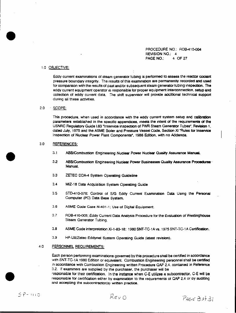
PROCEDURE NO.: ROB-410-004 REVISION NO.: 4 PAGE NO.: 4 OF 27
1.0 OBJECTIVE:
Eddy current examinations of steam generator tubing is performed to assess the reactor coolant pressure boundary integrity. The results of this examination are permanently recorded and used for comparison with the results of past and/or subsequent steam generator tubing inspection. The eddy current equipment operator is responsible for proper equipment interconnection, setup and collection of eddy current data. The shift supervisor will provide additional technical support during all these activities.
2.0 SCOPE:
This procedure, when used in accordance with the eddy current system setup and calibration parameters established in the specific appendices, meets the intent of the requirements of the USNRC Regulatory Guide 1.83 inservice inspection of PWR Steam Generator Tubes', Revision 1, dated July, 1975 and the ASME Boiler and Pressure Vessel Code, Section XI "Rules for Inservice Inspection of Nuclear Power Plant Components', 1986 Edition, with no Addenda.
3.0 REFERENCES:
3.1 ABB/Combustion Engineering Nuclear Power Nuclear Quality Assurance Manual.
3.2 ABB/Combustion Engineering Nuclear Power Businesses Quality Assurance Procedures Manual.
3.3 ZETEC DDA-4 System Operating Guideline
3.4 MIZ-18 Data Acquisition System Operating Guide
3.5 STD-410-076; Control of S/G Eddy Current Examination Data Using the Personal Computer (PC) Data Base System.
3.6 ASME Code Case N-401-1; Use of Digital Equipment.
3.7 ROB-410-005; Eddy Current Data Analysis Procedure for the Evaluation of Westinghouse Steam Generator Tubing.
3.8 ASME Code interpretation XI-1-83-18: 1980 SNT-TC-1A vs. 1975 SNT-TC-1A Certification.
3.9 HP-UX/Zetec Eddynet System Operating Guide (latest revision).
4.0 PERSONNEL REQUIREMENTS:
Each person performing examinations governed by this procedure shall be certified in accordance with SNT-TC-1A 1980 Edition or equivalent. Combustion Engineering personnel shall be certified in accordance with Combustion Engineering written Procedure QAP 2.4. contained in Reference 3.2. If examiners are supplied by the purchaser, the purchaser will be resoonsible for their certification. In the instance when C-E utilizes a subcontractor, C-E will be responsible for certification either by examination to the requirements of QAP 2.4 or by auditing and accepting the subcontractor(s) written practice.
PROCEDURE NO.: ROB-410-004 REVISION NO.: 4 PAGE NO.: 5 OF 27
4.1 A level I may perform specific calibrations and specific tests according to written instructions (procedure) and to record the results. He shall receive the necessary guidance or supervision from a certified ET Level II or III individual.
4.2 The initial equipment setup at the start of the test program shall be verified by a certified ET Level II or III individual.
4.3 The evaluation of the results of the eddy current examination must be conducted by a Data Analyst qualified to at least ET Level II with specific training for the evaluation of data from nonferromagnetic steam generator tubing.
5.0 PRECAUTIONS AND PREREQUISITES:
5.1 it is expected that very high levels of radiation may be encountered inside and adjacent to the primary head of the steam generators. Utmost care shall be taken in the setup and performance of the examination to minimize personnel exposure to ionizing radiation and radioactive contamination.
5.2 Personnel engaged in the eddy current examination program shall be indoctrinated in the radiation protection rules, guidelines, protective clothing and equipment requirements In effect at the plant site as required.
5.3 The eddy current test equipment will be set up in an area designated by the operator and approved by the site personnel in accordance with the appropriate figures and test setup instructions.
NOTE: If the Remote Data Acquisition and Analysis Trailer (RDAAT) is utilized, data acquisition equipment, video equipment and communication equipment may be located in this trailer.
5.4 The steam generator shall be open on the primary side dried and ventilated in such a manner as to provide proper temperature and humidity for personnel safety and comfort and to prevent heat and moisture damage to equipment (approximately 90 deg. F or less).
5.5 The secondary side of the steam generator shall be cooled down to the extent that the temperature of the tubes and tube sheet are 120 deg. F or less.
5.6 Provisions must be made for personnel and equipment entry into and exit from the steam generator (i.e., ladders, scaffolds or staging, platforms, lighting inside and outside the steam generator, breathing air supply, 120 VAC electricity, etc.).
5.7 Health Physics coverage shall be maintained at the steam generator during any personnel entry into the steam generator as required.
5.8 The Eddy Current Examination Sheets will list all the tubes that are to be inspected (Figure 1). The ET Operator will check each tube on the examination sheet after rt is inspected. Data control is maintained in accordance with Reference 3.5 or as applicalie.
FVc E7
PROCEDURE NO.: ROB-410-004 REVISION NO.: 4 PAGE NO.: 6 OF 27
5.9 NOTE: ALL EXAMINATION/INSPECTION FORMS, RECORDS, AND EXAMINATION SHEETS SHALL BE DATED AND SIGNED WHERE REQUIRED. "NA' SHALL BE WRITTEN OR TYPED IN ALL BLANKS- THAT ARE NOT APPUCABLE TO THE DOCUMENT. BLACK INK IS REQUIRED AND THE USE OF 'WHITE OUT' OR CORRECTION FLUID IS FORBIDDEN. CHANGES WILL BE SINGLE UNED THROUGH, INITIALED, AND DATED. UNUSED PORTIONS OF ANY FORMS SHALL BE UNED THROUGH WITH A SINGLE UNE INDICATING NO FURTHER ACTION.
5.10 A communication system will be setup and operating between the eddy current test instrument Operator and the steam generator platform.
5.11 The primary piping nozzle openings shall have been sealed prior to entry into the steam generator for eddy current testing equipment installation to eliminate the possibility of hardware inadvertently falling into the nozzle.
6.0 CAUBRATION STANDARDS:
6.1 The calibration standard will be fabricated from a length of tubing, of the same alloy, nominal outside diameter, and nominal wall thickness as that in the steam generator. It may also contain secondary side features such as carbon steel or stainless steel as support rings, copper rings, and other features as needed to provide signals for subsequent multi-parameter frequency mixing by the data analyst.
6.2 Documentation shall include an as-built drawing of the calibration standard, a mill test report, serial number and manufacture's heat treat number for tube material used in the calibration standard.
6.3 The ASME calibration standard will typically contain the following artificial discontinuities as a minimum but other designs may be used as required for specific applications. See Figure 2 for typical standard. Use as-built drawing of actual standard for specific details.
6.3.1 A single hole drilled 100% through wall 0.067 in. dia.
6.3.2 Flat-bottomed drill hole 5/64 in. dia. x 80% through from the outer tube wall surface.
6.3.3 Fiat-bottomed drill hole 7/64 in. dia. x 60% through from the outer tube wall surface.
6.3.4 Flat-bottomed drill hole 3/16 in. dia. x 40% through from the outer tube wall surface.
6.3.5 Four flat-bottomed drill hole 3/16 in. dia., spaced 90 deg. apart around the tube circumference, 20% through from the outer tube wall surface.
6.3.6 1/16 in. wide 360 deg. circumferential groove. 20% through from the inner tube wall surface.
PROCEDURE NO.: ROB-410-004 REVISION NO.: 4 PAGE NO.: 7 OF 27
6.3.7 1/8 in. wide 360 degrees circumferential groove 10% through from the outer tube wall surface.
6.4 The profile calibration standard (when used) will contain sufficient tube expansions and/or reductions in diameter to provide a set of known values for profile evaluations. See Figure 3 for typical standard. Use as-built drawing of the actual standard for specific details.
6.5 Other special calibration standards (when used) will contain a variety of notches, holes and grooves for calibration of special setups such as rotating probes. See Figure 4 for typical special calibration standard. Use as-built drawing of the actual standard for specific details.
7.0 EQUIPMENT:
All eddy current test equipment provided by Combustion Engineering shall be certified to be equivalent to or exceed the applicable requirements of the ASME Code, Section XI. Appendix IV, Paragraph IV-3100, with Code Case N-401-1 addressing the use of digital examination equipment. Documentation of calibration will be provided prior to the start of the inspection. A typical equipment list is provided below.
7.1 Computer System with Data Acquisition Software and a supply of storage media.
7.2 Data Cartridge Recorder and a supply of properly formatted storage media cartridges.
7.3 Remote Data Acquisition Unit (RDAU) as required.
7 4 Eddy Current test/reference probes. See appropriate appendix for probe size and type.
7.5 Remote controlled manipulator, eg. SM-10/SM-20.
7.6 Steam Generator Templates (optional).
7.7 Mechanical probe pusher and flexible probe guide material (optional).
7.8 A calibration and reference standard (hand held or in-line).
7.9 Eddy Current Examination Sheets.
7.10 Closed circuit television system (optional).
7.11 Communication system (optional).
8.0 EQUIPMENT SETUP:
8.1 Satisfy applicable requirements specified in Section 5. (Precautions and Prerequisites).
8.2 Set up communications between steam generator platform and data station as required.
8.3 install templates into the steam generator primary head as required.
PROCEDURE NO.: ROB-410-004 REVISION NO.: 4 PAGE NO.: 8 OF 27
8.4 Install the remote manipulator into the steam generator primary head as required.
8.5 Attach guide tube with flexible guide material between remote manipulator and the probe driver.
8.6 Interconnect the acquisition system as shown in Figure 5 and 6 described as follows:
8.6.1 Connect the General Purpose Input Output (GPIO) interface card on the (address 12) to the Data Cartridge Recorder with an appropriate cable. (When duplicating tapes, connect a second GPIO Interface Card at address 11 for the duplicate)
8.6.2 Connect the acquisition computer system (ACS) to the ACS/RDAU interface (HPIB or equiv.) with an appropriate cable.
8.6.3 Connect the ACS/RDAU Interface to the RDAU remote Unit with the desired lengths (500' to 1000' typical) of cable(s). The appropriate (IEEE-488 type) connector of the RDAU should be used. Interconnect the probe controller to the RDAU if the automated (Zetec 4d) probe pusher is used.
8.6.4 An appropriate probe splitter/adaptor connected to the PROBE connector on the RDAU is used to adapt the test probe to the RDAU.
8.7 Should absolute data be desired, the probe splitter/adaptor must have at least two probes; one probe attached to the connector labeled 'probe' and one probe attached to the connector labeled "ref'. The reference probe shall be placed in a reference standard. Ten foot extension cables or longer may be used as required. Typically the following splitter/adaptor will be utilized with the following probe types:
8.7.1 4 pin splitter/adaptor - bobbin probes.
3.7.2 10 pin splitter/adaptors - 8 x 1 probes, rotating probes, segmented bobbin probes. profilometry probes, etc. Other appropriate adaptors as required by probe design.
9.0 EQUIPMENT OPERATION AND CALIBRATION:
The following will describe the typical equipment calibration sequence with the specific calibration technique requirements described in Appendix A through D. The appropriate Appendix will be selected based on the particular type of inspection. The operator will be provided written instruction by the shift supervisor with the issue of a completed *Set Up Instruction' Form. See Figure 7.
9.1 Load data acquisition software into the right disk drive and a blank diskette into left disk drive.
9.2 Turn power on. Turn display intensity to desired readability.
9.3 The system will prompt the user into the set clock and date mode. Place the data cartridge into the data cartridge recorder with power activated; the cartridge will self-load.
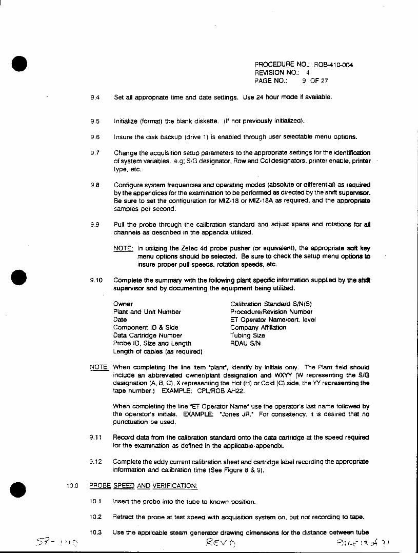
PROCEDURE NO.: ROB-410-004 REVISION NO.: 4 PAGE NO.: 9 OF 27
9.4 Set all appropriate time and date settings. Use 24 hour mode if available.
9.5 Initialize (format) the blank diskette. (if not previously initialized).
9.6 Insure the disk backup (drive 1) is enabled through user selectable menu options.
9.7 Change the acquisition setup parameters to the appropriate settings for the identification of system variables. e.g; S/G designator. Row and Col designators, printer enable, printer type, etc.
9.8 Configure system frequencies and operating modes (absolute or differential) as required by the appendices for the examination to be performed as directed by the shift supervisor. Be sure to set the configuration for MIZ-18 or MIZ-18A as required, and the appropriate samples per second.
9.9 Pull the probe through the calibration standard and adjust spans and rotations for all channels as described in the appendix utilized.
NOTE: In utilizing the Zetec 4d probe pusher (or equivalent), the appropriate soft key menu options should be selected. Be sure to check the setup menu options to insure proper pull speeds, rotation speeds, etc.
9.10 Complete the summary with the following plant specific information supplied by the shift supervisor and by documenting the equipment being utilized.
Owner Calibration Standard S/N(S) Plant and Unit Number Procedure/Revision Number Date ET Operator Name/cert. level Component ID & Side Company Affiliation Data Cartridge Number Tubing Size Probe ID, Size and Length RDAU S/N Length of cables (as required)
NOTE: When completing the line item "plant', identify by initials only. The Plant field should include an abbreviated owner/plant designation and WXYY (W representing the S/G designation (A, B, C), X representing the Hot (H) or Cold (C) side. the YY representing the tape number.) EXAMPLE: CPL/ROB AH22.
When completing the line 'ET Operator Name' use the operator's last name followed by the operator's initials. EXAMPLE: "Jones JR. For consistency, it is desired that no punctuation be used.
9.11 Record data from the calibration standard onto the data cartridge at the speed required for the examination as defined in the applicable appendix.
9.12 Complete the eddy current calibration sheet and cartridge label recording the aopropriate information and calibration time (See Figure 8 & 9).
10.0 PROBE SPEED AND VERIFICATION:
10.1 Insert the probe into the tube to known position.
10.2 Retract the probe at test speed with acquisition system on, but not recording to tape.
10.3 Use the applicable steam generator drawing dimensions for the distance between tube
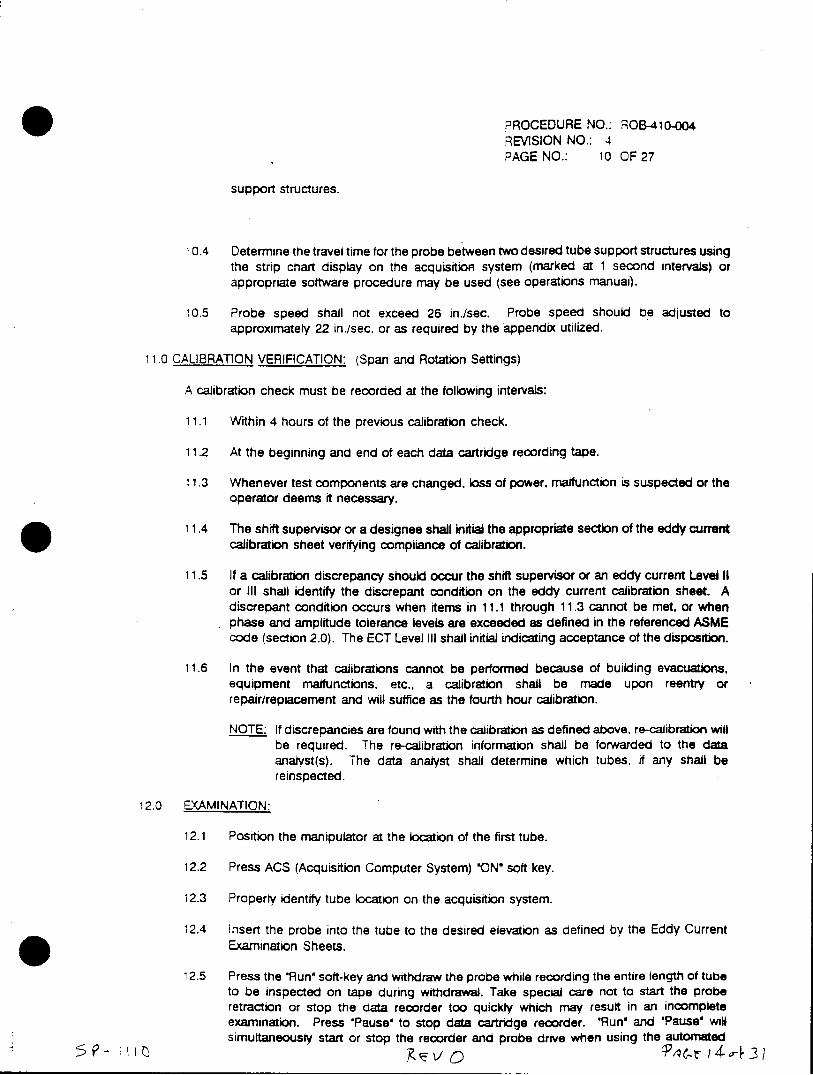
PROCEDURE NO.: ROB-410-OO4 REVISION NO.: 4 PAGE NO.: 10 OF27
support structures.
10.4 Determine the travel time for the probe between two desired tube support structures using the strip chart display on the acquisition system (marked at 1 second intervals) or appropriate software procedure may be used (see operations manual).
10.5 Probe speed shall not exceed 26 in./sec. Probe speed should be adjusted to approximately 22 in./sec. or as required by the appendix utilized.
11.0 CALIBRATION VERIFICATION: (Span and Rotation Settings)
A calibration check must be recorded at the following intervals:
11.1 Within 4 hours of the previous calibration check.
11.2 At the beginning and end of each data cartridge recording tape.
11.3 Whenever test components are changed. loss of power, malfunction is suspected or the operator deems it necessary.
11.4 The shift supervisor or a designee shall initial the appropriate section of the eddy current calibration sheet verifying compliance of calibration.
11.5 If a calibration discrepancy should occur the shift supervisor or an eddy current Level II or Ill shall identify the discrepant condition on the eddy current calibration sheet. A discrepant condition occurs when items in 11.1 through 11.3 cannot be met, or when phase and amplitude tolerance levels are exceeded as defined in the referenced ASME code (section 2.0). The ECT Level III shall initial indicating acceptance of the disposition.
11.6 In the event that calibrations cannot be performed because of building evacuations, equipment malfunctions, etc., a calibration shall be made upon reentry or repair/replacement and will suffice as the fourth hour calibration.
NOTE: If discrepancies are found with the calibration as defined above. re-calibration will be required. The re-calibration information shall be forwarded to the data analyst(s). The data analyst shall determine which tubes, if any shall be reinspected.
12.0 EXAMINATION:
12.1 Position the manipulator at the location of the first tube.
12.2 Press ACS (Acquisition Computer System) 'ON' soft key.
12.3 Property identify tube location on the acquisition system.
12.4 Insert the crobe into the tube to the desired elevation as defined by the Eddy Current Examination Sheets.
12.5 Press the *Run' soft-key and withdraw the probe while recording the entire length of tube to be inspected on tape during withdrawal. Take special care not to start the probe retraction or stop the data recorder too quickly which may result in an incomplete examination. Press 'Pause' to stop data cartridge recorder. 'Run' and 'Pause' will simultaneously start or stop the recorder and probe drive when using the automated
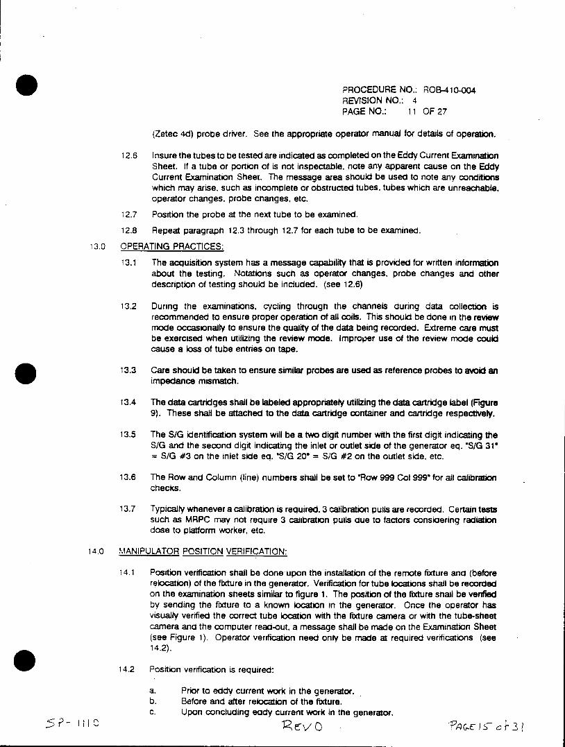
PROCEDURE NO.: ROB-410-004 REVISION NO.: 4 PAGE NO.: 11 OF 27
(Zetec 4d) probe driver. See the appropriate operator manual for details of operation.
12.6 Insure the tubes to be tested are indicated as completed on the Eddy Current Examination Sheet. If a tube or portion of is not inspectable, note any apparent cause on the Eddy Current Examination Sheet. The message area should be used to note any conditions which may arise, such as incomplete or obstructed tubes, tubes which are unreachable, operator changes, probe changes, etc.
12.7 Position the probe at the next tube to be examined.
12.8 Repeat paragraph 12.3 through 12.7 for each tube to be examined.
13.0 OPERATING PRACTICES:
13.1 The acquisition system has a message capability that is provided for written information about the testing. Notations such as operator changes, probe changes and other description of testing should be included. (see 12.6)
13.2 During the examinations, cycling through the channels during data collection is recommended to ensure proper operation of all coils. This should be done in the review mode occasionally to ensure the quality of the data being recorded. Extreme care must be exercised when utilizing the review mode. Improper use of the review mode could cause a loss of tube entries on tape.
13.3 Care should be taken to ensure similar probes are used as reference probes to avoid an impedance mismatch.
13.4 The data cartridges shall be labeled appropriately utilizing the data cartridge label (Figure 9). These shall be attached to the data cartridge container and cartridge respectively.
13.5 The S/G identification system will be a two digit number with the first digit indicating the S/G and the second digit indicating the inlet or outlet side of the generator eq. 'S/G 310 = S/G #3 on the inlet side eq. "S/G 208 = S/G #2 on the outlet side. etc.
13.6 The Row and Column (line) numbers shall be set to 'Row 999 Col 999" for all calibration checks.
13.7 Typically whenever a calibration is required, 3 calibration pulls are recorded. Certain tests such as MRPC may not require 3 cahibration pulls due to factors consiaering radiation dose to platform worker, etc.
14.0 MANIPULATOR POSITION VERIFICATION:
14.1 Position verification shall be done upon the installation of the remote fixture and (before relocation) of the fixture in the generator. Verification for tube locations shall be recorded on the examination sheets similar to figure 1. The position of the fixture shall be verified by sending the fixture to a known location in the generator. Once the operator has visually verified the correct tube location with the fixture camera or with the tube-sheet camera and the computer read-out, a message shall be made on the Examination Sheet (see Figure 1). Operator verification need only be made at required verifications (see 14.2).
14.2 Position verification is required:
a. Prior to eddy current work in the generator. b. Before and after relocation of the fixture. c. Upon concluding eddy current work in the generator.
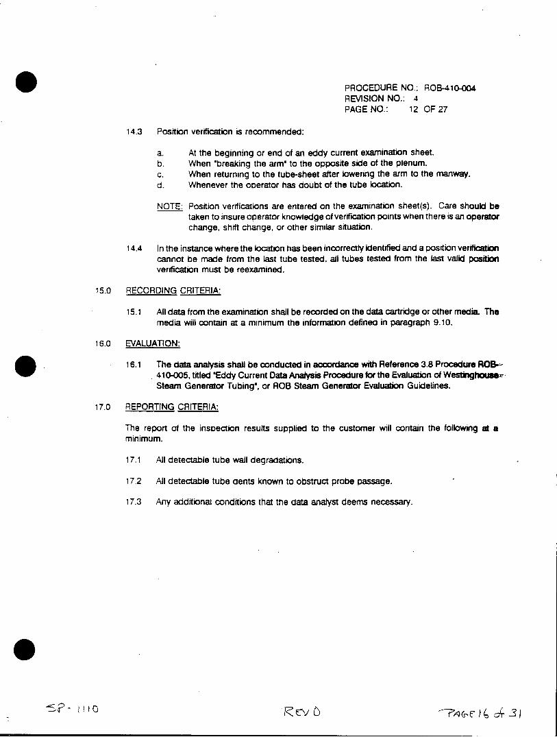
PROCEDURE NO.: ROB-410-004 REVISION NO.: 4 PAGE NO.: 12 OF 27
14.3 Position verification is recommended:
a. At the beginning or end of an eddy current examination sheet. b. When 'breaking the arm' to the opposite side of the plenum. c. When returning to the tube-sheet after lowering the arm to the manway. d. Whenever the operator has doubt-of the tube location.
NOTE: Position verifications are entered on the examination sheet(s). Care should be taken to insure operator knowledge of verification points when there is an operator change, shift change, or other similar situation.
14.4 In the instance where the location has been incorrectly identified and a position verification cannot be made from the last tube tested, all tubes tested from the last valid position verification must be reexamined.
15.0 RECORDING CRITERIA:
15.1 All data from the examination shall be recorded on the data cartridge or other media. The media will contain at a minimum the information defined in paragraph 9.10.
16.0 EVALUATION:
16.1 The data analysis shall be conducted in accordance with Reference 3.8 Procedure ROB410-005, titled 'Eddy Current Data Analysis Procedure for the Evaluation of Westinghousex Steam Generator Tubinga, or ROB Steam Generator Evaluation Guidelines.
17.0 REPORTING CRITERIA:
The report of the inspection results supplied to the customer will contain the following at a minimum.
17.1 All detectable tube wall degradations.
17.2 All detectable tube dents known to obstruct probe passage.
17.3 Any additional conditions that the data analyst deems necessary.
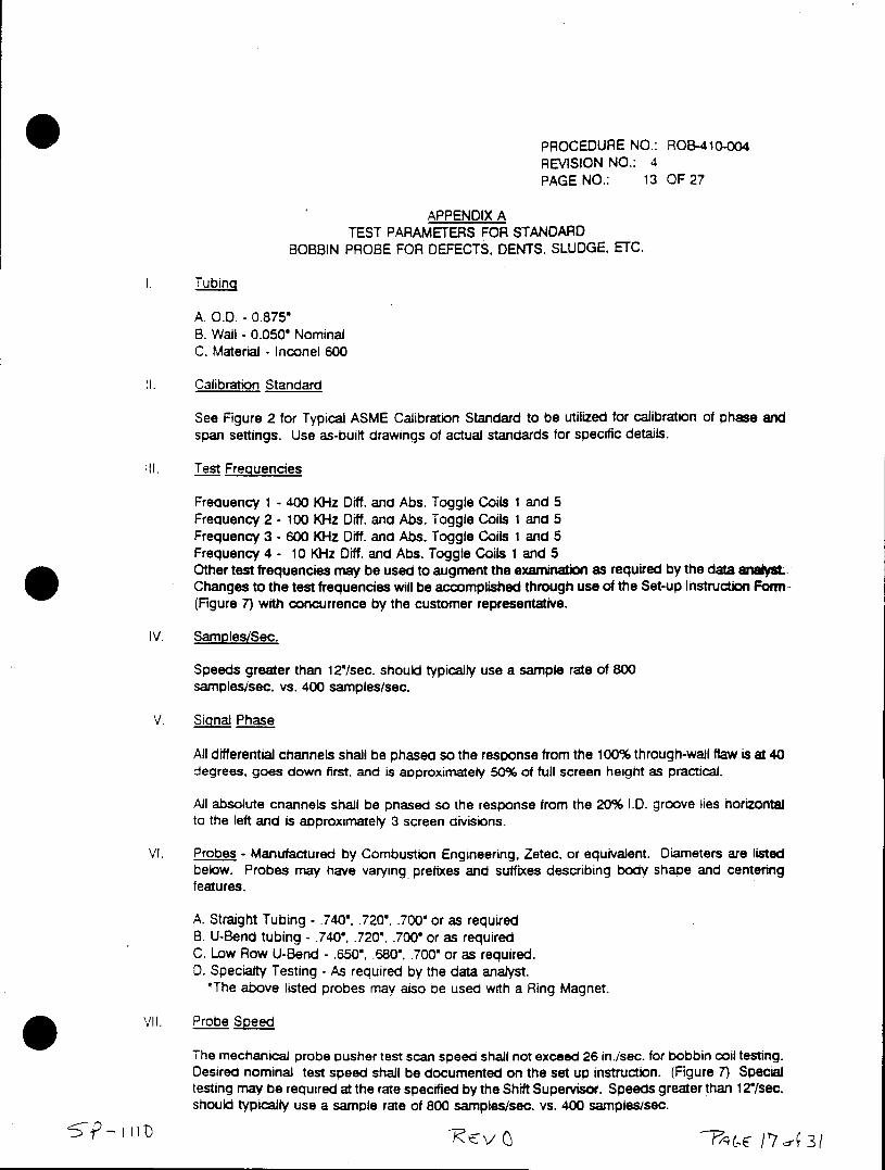
PROCEDURE NO.: ROB-410-004 REVISION NO.: 4 PAGE NO.: 13 OF 27
APPENDIX A TEST PARAMETERS FOR STANDARD
BOBBIN PROBE FOR DEFECTS, DENTS. SLUDGE. ETC.
Tubing
A. O.D. - 0.875' B. Wall - 0.050" Nominal C. Material - Inconel 600
1. Calibration Standard
See Figure 2 for Typical ASME Calibration Standard to be utilized for calibration of phase and span settings. Use as-built drawings of actual standards for specific details.
III. Test Frequencies
Frequency 1 - 400 KHz Diff. and Abs. Toggle Coils 1 and 5 Frequency 2 - 100 KHz Diff. and Abs. Toggle Coils 1 and 5 Frequency 3 - 600 KHz Diff. and Abs. Toggle Coils 1 and 5 Frequency 4 - 10 KHz Diff. and Abs. Toggle Coils 1 and 5 Other test frequencies may be used to augment the examination as required by the data analyst. Changes to the test frequencies will be accomplished through use of the Set-up Instruction Form (Figure 7) with concurrence by the customer representative.
IV. Samples/Sec.
Speeds greater than 12*/sec. should typically use a sample rate of 800 samples/sec. vs. 400 samples/sec.
V. Signa Phase
All differential channels shall be phased so the response from the 100% through-wall flaw is at 40 degrees, goes down first, and is approximately 50% of full screen height as practical.
All absolute channels shall be phased so the response from the 20% I.D. groove lies horizontal to the left and is approximately 3 screen divisions.
VI. Probes - Manufactured by Combustion Engineering, Zetec, or equivalent. Diameters are listed below. Probes may have varying prefixes and suffixes describing body shape and centering features.
A. Straight Tubing - .740', .720", .700" or as required B. U-Bend tubing - .740*, .720', .700' or as required C. Low Row U-Bend - .650', .680', .700" or as required. D. Specialty Testing - As required by the data analyst.
*The above listed probes may also be used with a Ring Magnet.
VIl. Probe Speed
The mechanical probe pusher test scan speed shall not exceed 26 in./sec. for bobbin coil testing. Desired nominal test speed shall be documented on the set up instruction. (Figure 7) Special testing may be required at the rate specified by the Shift Supervisor. Speeds greater than 12"Isec. should typically use a sample rate of 800 samples/sec. vs. 400 samples/sec.
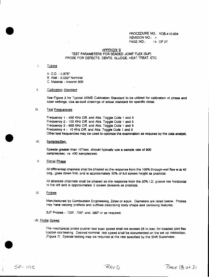
PROCEDURE NO.: ROB-410-004 REVISION NO.: 4 PAGE NO.: 14 OF 27
APPENDIX B TEST PARAMETERS FOR BEADED JOINT FLEX (BJF)
PROBE FOR DEFECTS. DENTS, SLUDGE, HEAT TREAT, ETC.
1. Tubing
A. O.D. - 0.8750 B. Wall - 0.050" Nominal C. Material - Inconel 600
II. Calibration Standard
See Figure 2 for Typical ASME Calibration Standard to be utilized for calibration of phase and span settings. Use as-built drawings of actual standard for specific detail.
Ill. Test Frequencies
Frequency 1 - 400 KHz Oiff. and Abs. Toggle Coils 1 and 5 Frequency 2 - 100 KHz Dff. and Abs. Toggle Coils 1 and 5 Frequency 3 - 600 KHz Diff. and Abs. Toggle Coils 1 and 5 Frequency 4 - 10 KHz Diff. and Abs. Toggle Coils 1 and 5 Other test frequencies may be used to optimize the examination as required by the data analyst.
IV. Samples/Sec.
Speeds greater than 12"/sec. should typically use a sample rate of 800 samples/sec. vs. 400 samples/sec.
V. Sgjng! Phase
All differential channels shall be phased so the response from the 100% through-wall flaw is at 40 deg., goes down first, and is approximately 50% of full screen height as practical.
All absolute channels shall be phased so the response from the 20% I.D. groove lies horizontal to the left and is approximately 3 screen divisions as practical.
VI. Probes
Manufactured by Combustion Engineering, Zetec or equiv. Diameters are listed below. Probes may have varying prefixes and suffixes describing body shape and centering features.
BJF Probes - .720', .700', and .680' or as required.
VII. Probe Speed
The mechanical probe pusher test scan speed shall not exceed 26 in./sec. for beaded joint flex bobbin coil testing. Desired nominal test speed shall be documented on the set up instruction. (Figure 7) Special testing may be required at the rate specified by the Shift Supervisor.
*0
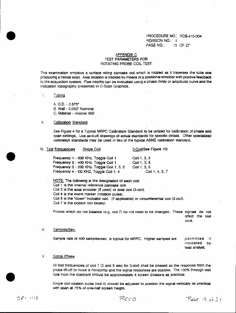
PROCEDURE NO.: ROB-410-004 REVISION NO.: 4 PAGE NO.: 15 OF 27
APPENDIX C TEST PARAMETERS FOR
ROTATING PROBE COIL TEST
This examination employs a surface riding pancake coil which is rotated as it traverses the tube axis producing a helical scan. Axial location is tracked by means of a positional encoder with positive feedback to the acquisition system. Flaw depths can be evaluated using a phase delay or amplitude curve and the indication topography presented in C-Scan Graphics.
I . Tubing
A. O.D. - 0.875" B. Wall - 0.050' Nominal C. Material - Inconel 600
II. Calibration Standard
See Figure 4 for a Typical MRPC Calibration Standard to be utilized for calibration of phase and span settings. Use as-built drawings of actual standards for specific details. Other specialized calibration standards may be used in lieu of the typical ASME calibration standard.
III. Test Frequencies Single Coil 3-Coil(See Figure 10)
Frequency 1 - 800 KHz. Toggle Coil 1 Coil 1, 3, 5 Frequency 2 - 400 KHz, Toggle Coil 1 Coil 1, 3, 5 Frequency 3 - 200 KHz, Toggle Coil 1, 3, 5 Coil 1, 3, 5 Frequency 4 - 100 KHZ, Toggle Coil 1, 4 Coil 1, 4, 5, 7
NOTE: The following is the designation of each coil: Coil 1 is the internal reference pancake coil. Coil 3 is the axial encoder (if used] or axial coil (3-coi). Coil 4 is the event marker (rotation pulse). Coil 5 is the 'down, indicator coil. (If applicable) or circumferential coil (3-coi). Coil 7 is the bobbin coil locator.
Probes which do not balance (e.g. coil 7) do not need to be changed. These signals do not affect the test coils.
IV. Samples/Sec.
Sample rate of 400 samples/sec. is typical for MRPC. Higher samples are permitted if indicated by lead analyst.
V. Signal Phase
All test frequencies of coil 1 (3 and 5 also for 3-coi) shall be phased so the response from the probe lift-off or noise is horizontal and the signal responses are positive. The 100% through wall hole from the standard should be approximately 4 screen divisions as practical.
Single coil rotation pulse (coil 4) should be adjusted to position the signal vertically as practical with span at 75% of one-half screen height.
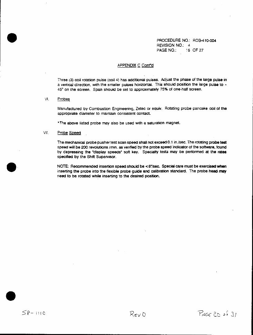
PROCEDURE NO.: ROB-410-004 REVISION NO.: 4 PAGE NO.: 16 OF 27
APPENDIX C Cont'd
Three (3) coil rotation pulse (coil 4) has additional pulses. Adjust the phase of the large pulse in a vertical direction, with the smaller pulses horizontal. This should position the large pulse to 450 on the screen. Span should be set to approximately 75% of one-half screen.
VI. Probes
Manufactured by Combustion Engineering, Zetec or equiv. Rotating probe pancake coil of the appropriate diameter to maintain consistent contact.
*The above listed probe may also be used with a saturation magnet.
VII. Probe Speed
The mechanical probe pusher test scan speed shall not exceed 0.1 in./sec. The rotating probe test speed will be 200 revolutions imin. as venfied by the probe speed indicator of the software, found by depressing the *display speeds' soft key. Specialty tests may be performed at the rates specified by the Shift Supervisor.
NOTE: Recommended insertion speed should be <6 /sec. Special care must be exercised when inserting the probe into the flexible probe guide and calibration standard. The probe head may need to be rotated while inserting to the desired position.
5p~- I v
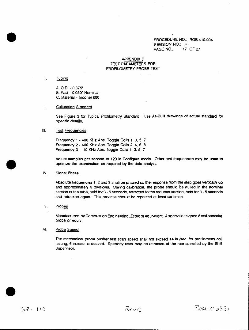
PROCEDURE NO.: ROB-410-004 REVISION NO.: 4 PAGE NO.: 17 OF 27
APPENDIX D TEST PARAMETERS FOR
PROFILOMETRY PROBE TEST
1. Tubing
A. O.D. - 0.8750 B. Wall - 0.050' Nominal C. Material - Inconel 600
1l. Calibration Standard
See Figure 3 for Typical Profilometry Standard. Use As-Built drawings of actual standard for specific details.
III. Test Frequencies
Frequency 1 - 400 KHz Abs. Toggle Coils 1, 3, 5, 7 Frequency 2 - 400 KHz Abs. Toggle Coils 2, 4, 6, 8 Frequency 3 - 10 KHz Abs. Toggle Coils 1, 3, 5, 7
Adjust samples per second to 120 in Configure mode. Other test frequencies may be used to optimize the examination as required by the data analyst.
IV. Signal Phase
Absolute frequencies 1, 2 and 3 shall be phased so the response from the step goes vertically up and approximately 3 divisions. During calibration, the probe should be nulled in the nominal section of the tube, held for 3 - 5 seconds, retracted to the reduced section, held for 3 -5 seconds and retracted again. This process should be repeated at least six times.
V. Probes
Manufactured by Combustion Engineering, Zetec or equivalent. A special designed 8 coil pancake probe or equiv.
VI. Probe Soeed
The mechanical probe pusher test scan speed shall not exceed 14 in./sec. for profilometry coil testing, 6 in./sec. is desired. Specialty tests may be retracted at the rate specified by the Shift Supervisor.
litt:-
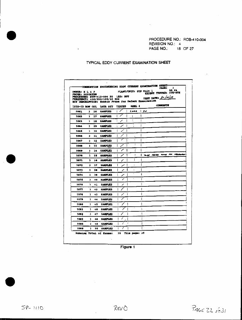
PROCEDURE NO.: ROB-41o-0o4 REVISION NO.: 4 PAGE NO.: 18 OF 27
TYPICAL EDDY CURRENT EXAMINATION SHEET
ox DiaIynm v=i cuw ZIm~axm
00111M Ka & P LN/m Sp unit 1 9 mu3h A 20*7m PLIJK/WU TSTW Crz-u.z
PROCZI BTP-410-004 10 L=S, HO F9ZO013hf 400/200/100/10 USx lUST VMS ______
WC! 083CPTX15 Bobbin ftg~e for D6ZCt ZM5U.1.0
ISIS-ID 2W COL DATA SET TUT= RZI.*
5041, 3 26 SAWXZ2 I ±1944 p
50" 3 27 SAI /'I soa2 3 28 SAWLU32
5064 3 a3 SAW=Z 7I 5045 3 30 SANWZ 7 5044 3 31. 5A1Z2 i
5047 3 32 3M01.=f
50ue 3 33 SANK= I7
5045L 3 34 SAWFU 5070 3 37 8882 I IM wM
5073 3 36 8A1zr /I 5074 3 33 Siim .F 5072 3 47 BSW12 .- I 5074 3331 SAmpm 1 5077 3 40 SAM1
5074 3 43 SAIRFUM I/ 5077 3 42 SAIWIZ 7-T5070 3 45 SAXYZ3M 7 50713 3 44 5AKw1 IT
5032 3 47 SAMWZ 1/ 7 _________
5082 3 43 SAKZ2 77,. 503" 3 43 aA1WLZ2
50111 3 50 S.AIPUMZ
ib=a~n Total of Excama 50 Thin Paqs$ 25
Figure 1
~ IlIv
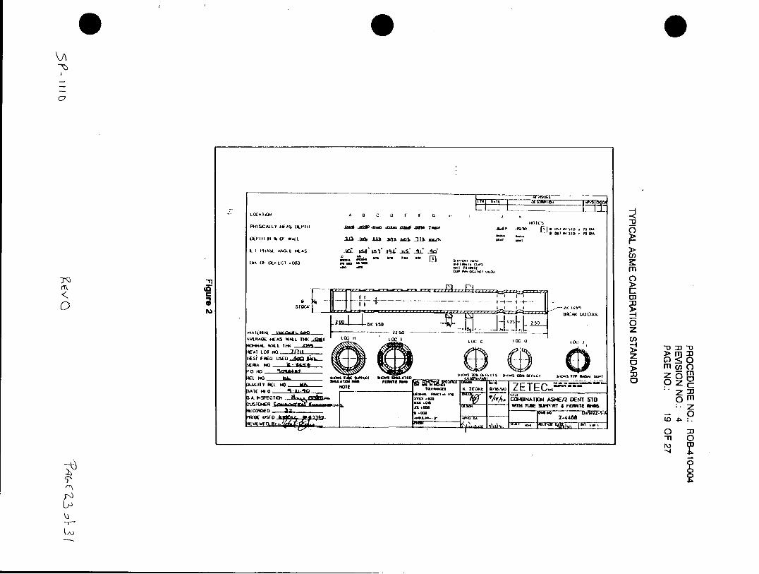
PHYSICAL.LY WkA~i (JLI'H .0" AQV -01.0 m a" w .~ w Ad. ~ j .~,. a-El as? I
C I flHASE MII k * AS LE IMLS IK 41 a.i: -!a
DA~ (I)- OE:CT .003 . a,,aa, .m
Fa TI 0
coc
11e1 ISO 0C N .. Pl
MAEFA ZZ5,40 zGAD ~ 2DN T
kVL~~~~~~~~k"~~A 64A AL.KMO1LcIc.c c0c IU
I (o~ :1)
NO~~~- 0%~L"7
AFL o KA I'm&rp T O M I ' o m z c 3LA TRLN
-C'JI -oTEETE Z3NTNAMn ETSO
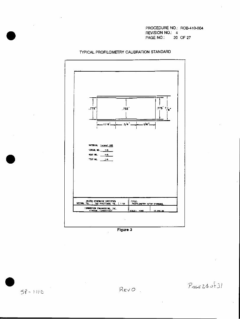
PROCEDURE NO.: ROB-410-004
REVISION NO.: 4
PAGE NO.: 20 OF 27
TYPICAL PROFILOMETRY CALIBRATION STANDARD
T T75.
.7
PATIIL [-.cowl 6WC
SERIAL NO. 4/4
HEAT 00. I/A
13? no. i/A
JIL TSO151i3 SKVZFTED I lTI
Figure 3
~~E 0Ic 17l
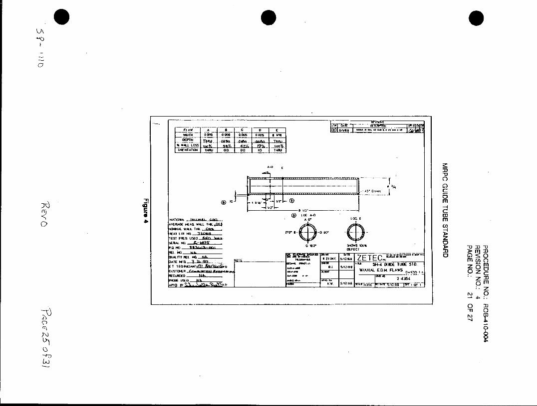
WMTN Go(w 0005 o8Lm 0006 a
% WALL. L=
A-0
- m4 ()VERAGE ME WALL 114Cl j
AL WALL IlICK
TEST FR~a~ US OLPECT 23 > I
)AT UaI L."'5 .. E 28ta WItW 5/12/80 7 ETE ) C 0 vfcv ta- - i" S4 0LJE TUBE 5T0. Z5 M
U)-Mf W/AX - IAL EDK FLAWS D.0510 z CEcmo ..... 2-4354 Z 33
o Z3
N
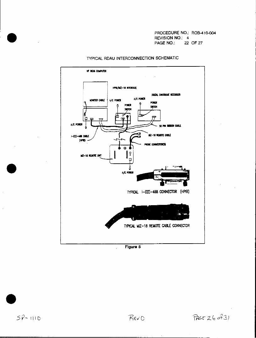
PROCEDURE NO.: ROB-410-004 REVISION NO.: 4 PAGE NO.: 22 OF 27
TYPICAL RDAU INTERCONNECTION SCHEMATIC
ms coneT~
PW1/t-18 MEW=M
M~u CalE A/C POaAXER
-48CaL I-EEl-48 CONNECTOR (HPIB)
-YPICAL Z-18 1OTE CABLE CONNECTOR
Figure 5
* Cw Z2
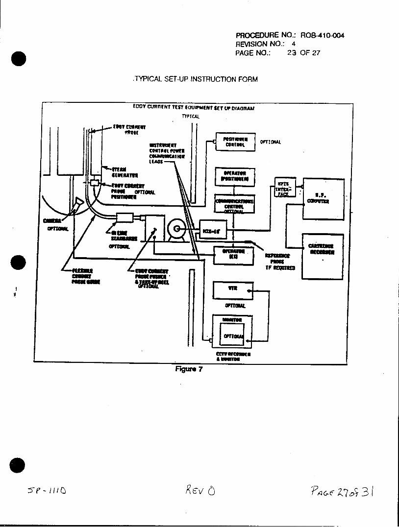
PROCEDURE NO.: ROB-410-004 RE\/ISION NO.: 4 PAGE NO.: 23 OF 27
.TYPICAL SET-UP INSTRUCT10N FORM
EDDY CURMl T TUT *GU WMENT CE LOP IOlAAI TYPYICAL
Inv culoIW
F@UTUU OF" OROAL. cuivaut
cmplt Fowlf CGUAN&nuring
Ftgre
0o I 5e-FA Ong~ k1v
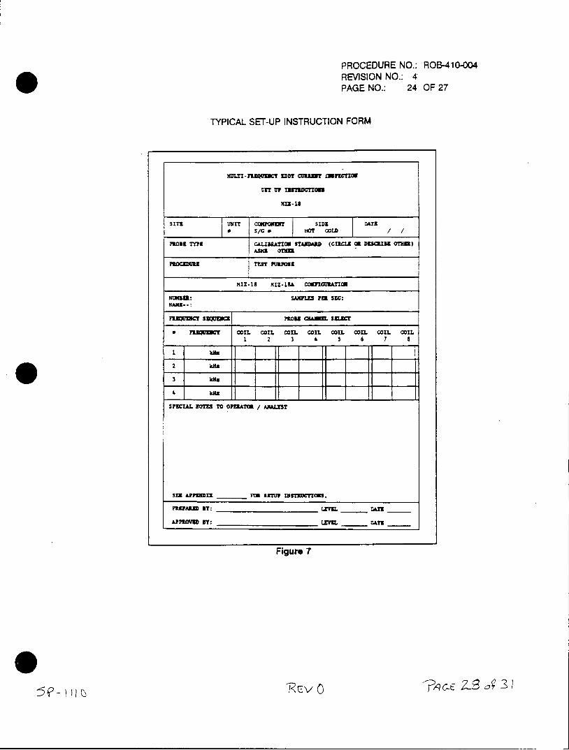
PROCEDURE NO.: ROB-410-004 REVISION NO.: 4 PAGE NO.: 24 OF 27
TYPICAL SET-UP INSTRUCTION FORM
waLT-nzl~uC!T aDD cmun to O
SET UP 11573D0=100
K-18
3 T T WET OSIDS D2ATE Ir S/C 0 O CoLD /
PROMTYP MAION STAMAZD (CRCLS OR DESRIBE OTHER)
KIZ-13 MIZ.19A COWICURAnO
NliGU: SAXPLES FEE SEC:
F3.ZJUCT S~IE PROME OLMU. SELEC
* illwa COMl COIL COIL COIL COIL COIL COIL COIL 1 2 3 ' 5 6 7 8
SPECIAL NoTES To OPEAT/ ANALYT
SEX APPMTX ______Ft sETu? xxsmmc.
PD.UAMf BT: ____________ EVEL DATE ___
ALPPEOYD BY: _____________ E~vEL___ DATE
Figure 7
5~-R--vO
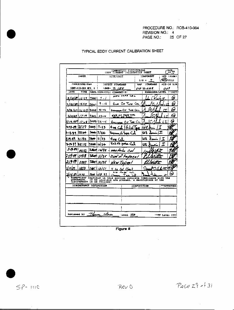
PROCEDURE NO.: ROB-410-004 REVISION NO.: 4 PAGE NO.: 25 OF 27
TYPICAL EDDY CURRENT CAUBRATION SHEET
-="UST:::: E:1:::;ZRTG
1n~ -DDT zw ='-R T~ca j EX .WNTR =xpQN~OENT E fls
7 ?ROCEMM/Rev L~rC? TMA "SWAD4Z1 I
L II
2// ii* 5:4 ~ . kw' I rT CIL AL(
f-" :17 3M17-ti
Is 24. 4?/4 10 C-1 QL
1-9? __ ,, / 1/r ~,A ~
e fm [§4Qt4&3 1zrviso In ialt in this section in&1.cescomLance witz Mel
ii.-.0dr It n IgiC are present. do *8cri ciafl Viar
ftevme~ by _avqi -- j 1**-T Level=:
Figure 8
0P - Z 3
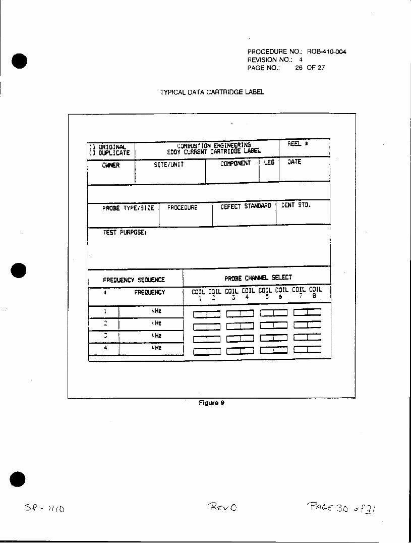
PROCEDURE NO.: ROB-410-004 REVISION NO.: 4 PAGE NO.: 26 OF 27
TYPICAL DATA CARTRIDGE LABEL
(I ORIGINAL COMBUSTION ENGINEERING REEL W (3 DUPLICATE EDDY CURRENT CARTRIDGE LASEL
OWNER SITE/UNIT COMPONENT LES DATE
PROB1E TYPE/SIZE PRO1CEDUE DEFECT STAND)ARD DENT STD.
TEST FURPOSEs
FREQUENCY SEQUENCE PROBE CHANNEL SELECT
FREQUENCY COIL COIL COIL COIL COIL COIL COIL COIL 1 3 4 5 6 7 8
1 KHz
Figure 9
'9v
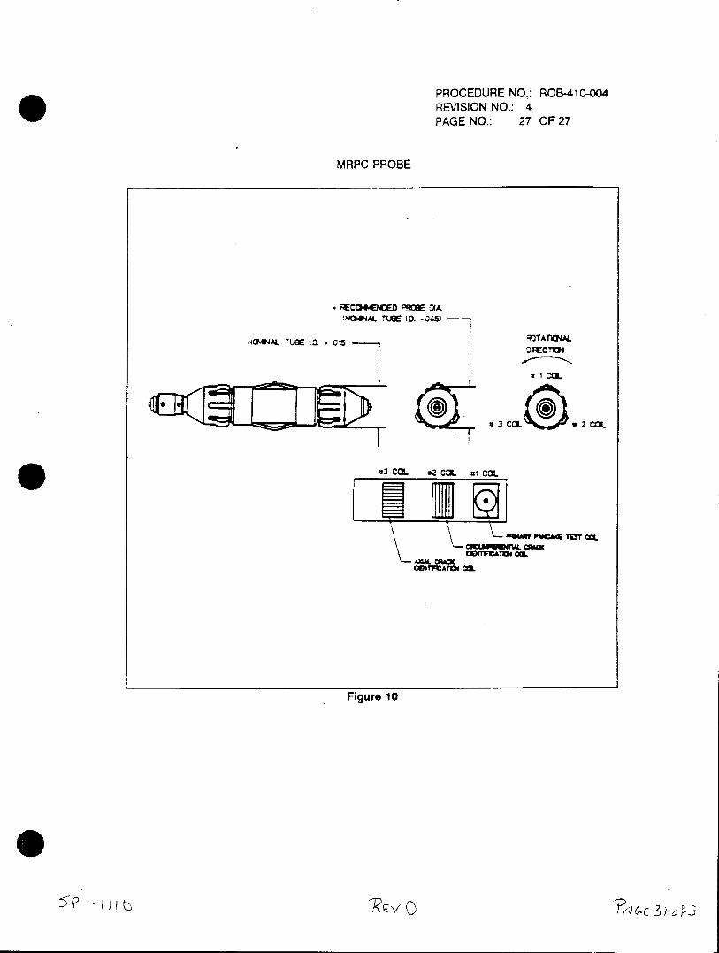
PROCEDURE NO.: ROB-410-004 REVISION NO.: 4 PAGE NO.: 27 OF 27
MRPC PROBE
- RECO4ceo .. cw oI NC~MA TUBE 1D -.0451
~ ru~ ~ *ROTWrOAL
u1 CC.
01.M PMCMM TOST tZ
CENTFCATCN CO.
Figure 10
CAROLINA POWER AND LIGHT COMPANY H.B. ROBINSON SEG PLANT
SPECIAL PROCEDURE
SP-1111
EDDY CURRENT DATA ANALYSIS PROCEDURE EVALUATION OF WESTINGHOUSE STEAM GENERATOR TUBING
REVISION 0 Off L E CONTROLLED RECIPIENT
Effective Date
Expiration Date )"/7~
RECOMMENDED BY: ,__ _ _ _ _ 4-
SXpervisor - Technical Support Date
APPROVED BY: A;_SL__7
Manag r - Techyical Support DAte
SP-1111 REV 0 PAGE 1 of 50
LIST OF EFFECTIVE PAGES
EFFECTIVE PAGES REVISION
Cover Sheet 0
LEP 0
3 through 50 0
SP-1111 REV 0 PAGE 2 of 50
TABLE OF CONTENTS
SECTION TITLE
1.0 Prerequisites
2.0 Precautions
3.0 Attachment
3.1 Eddy Current Data Analysis Procedure Evaluatio. of Westinghouse Steam Generator Tubing
3.2 H.B. Robinson Eddy Current Analysis Supplement
4.0 Disposition of Records
SP-1111 REV 0 PAGE 3 of 50
1.0 PREREQUISITES
Ensure individuals are on an appropriate RWP if work is to be performed inside the Radiation Control Area.
This procedure has been reviewed per PLP-037 and it has been determined NOT to be applicable.
Unit / Section Manager Date
2.0 PRECAUTIONS
Use the principles of ALARA in planning and performing work and operations in the Radiation Control Area.
3.0 ATTACHMENT
3.1 Eddy Current Data Analysis Procedure Evaluation of Westinghouse Steam Generator Tubing.
3.2 H.B. Robinson Eddy Current Analysis Supplement
4.0 DISPOSITION OF RECORDS
A copy of this procedure and the completed attachments shall be sent to the records vault for storage.
SP-1111 REV 0 PAGE 4 of 50
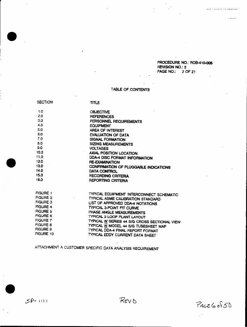
PROCEDURE NO.: ROB-4io-005 REVISION NO.: 3 PAGE NO.: 2 OF 21
TABLE OF CONTENTS
SECTION TITLE
1.0 OBJECTIVE 2.0 REFERENCES 3.0 PERSONNEL REQUIREMENTS 4.0 EQUIPMENT 5.0 AREA OF INTEREST 6.0 EVALUATION OF DATA 7.0 SIGNAL FORMATION 8.0 SIZING MEASUREMENTS 9.0 VOLTAGES 10.0 AXIAL POSION LOCATION 11.0 DDA-4 DISC FORMAT INFORMATION 12.0 RE-EXAMINATION 13.0 CONFIRMATION OF PLUGGABLE INDICATIONS 14.0 DATA CONTROL 15.0 RECORDING CRITERIA 16.0 REPORTING CRITERIA
FIGURE 1 TYPICAL EQUIPMENT INTERCONNECT SCHEMATIC FIGURE 2 TYPICAL ASME CAUBRATION STANDARD FIGURE 3 UST OF APPROVED DDA-4 NOTATIONS FIGURE 4 TYPICAL 3-POINT FIT CURVE FIGURE 5 PHASE ANGLE MEASUREMENTS FIGURE 6 TYPICAL 3 LOOP PLANT LAYOUT FIGURE 7 TYPICAL W SERIES 44 S/G CROSS SECTIONAL VIEW FIGURE 8 TYPICAL W MODEL 44 S/G TUBESHEET MAP FIGURE 9 TYPICAL DDA-4 FINAL REPORT FORMAT FIGURE 10 TYPICAL EDDY CURRENT DATA SHEET
ATTACHMENT A CUSTOMER SPECIFIC DATA ANALYSIS REQUIREMENT
PROCEDURE NO.: ROB410-005REVISION NO.: 3 PAGE NO.: 3 OF 21
1.0 OBJECTIVE
This procedure will establish a set of guidelines to be utilized by the eddy current Data Analyst wirtheintent of providing a consistent method for reporting the eddy current results. THIS PROCEDURE IS NOT INTENDED TO BE UTIUZED BY AN INDIVIDUAL WHO HAS NOT HAD PROPER TRAJNING INTHE EVALUATION OF EDDY CURRENT DATA. This procedure may be superseded in its entirety or in part by client specific analysis guidelines.
2.0 REFERENCES
2.1 A88/Combustion Engineering Nuclear Power Quality Assurance Manual.
2.2 ABB/Combustion Engineering Nuclear Power Businesses, Nuclear Quality Assurance Manual.
2.3 Zetec DDA-4 System Operating Guideline.
2.4 STD-410-076 Procedure for the control of Eddy Current examination data for the personak computer (PC) Data Base System.
2.5 ASME Code interpretation X1-83-18: 1980 SNT-TC-1A vs. 1975 SNT-TC-1A Certification:
2.6 HP-UX/Zetec Eddynet System Operating Guide (latest revision).
2.7 ASME Code Case N-401-1, use of digital equipment.
3.0 PERSONNEL REQUIREMENTS
3.1 The evaluation of the results of the eddy current examination must be conducted by a Data Analyst qualified to at least ET Level II with specific training for the evaluation of data from nonferrogmagnetic steam generator tubing.
3.2 Each person performing Data Analysis governed by this procedure shall be certified in accordance with SNT-TC-1A 1980 Edition or equivalent. Combustion Engineering personnel shall be certified in accordance with Combustion Engineering written Procedure QAP 2.4 contained in Reference 2.1.
If data analysts are supplied for primary or secondary data review by the purchaser, the purchaser will be responsible for their certification. In the instance when C-E utilized a subcontractor for primary or secondary data review. C-E will be responsible for certification either by examination to the requirements of QAP 2.4 or by auditing and accepting the subcontractor(s) written practice.
3.3 The Analyst shall be responsible for evaluating the data and reporting the results of the examination.
3.4 The independent data analyst (if used) shall be responsible for evaluating the data provided by the data controller.
PROCEDURE NO.: ROB.410-005 REVISION NO.: 3 PAGE NO.: 4 OF 21
4.0 EQUIPMENT
The equipment required to analyze the eddy current examination data includes but is not limited to the following: (Interconnect as appropriate). If LAN System is used, configuration may differ.
4.1 HP 200/300/400 Series Computer or equivalent.
4.2 Zetec Analysis software or equivalent.
4.3 Ample supply of floppy disks, data cartridges or applicable media.
4.4 Data Cartridge Recorder HCD-75Z, ADIC or equivalent media.
4.5 Appropriate printer or equivalent device (optional).
4.6 Eventide Expressway Intelligent Buffer Model WPB-109 or equivalent (optional).
4.7 Appropriate interconnect cables, power cords and peripherals.
5.0 AREA OF INTEREST
The evaluation of data shall include all information recorded on storage media per the requiremenftfa the Data Acquisition operating procedure in use or as specified by the client.
7A *.
PROCEDURE NO.: ROB-410-M REVISION NO.: 3 PAGE NO.: 5 OF 21
6.0 EVALUATION OF DATA
6.1 The data evaluation shall be conducted by viewing the lissajous pattern and the appropates strip chart presentations on the computer screen for the entire recorded length of each tuberzAny abnormal signals will be investigated for determination of location and percent through wall dimension (% TWD) as practical.
6.2 The screening frequencies utilized for the data analysis shall be the optimum defect detectionfrequencies for the size and wall thickness of the tubing being inspected. These frequenciese will be determined by the lead data analyst and documented on Attachment A, Client SpeciicData Analysis Requirements. No Field Change Noticq (FCN) is required for additions ordeletions to Attachment A. Signatures by the ET Level Ill and the client representative worepresent concurrence of the specific requirements.
NOTE: As work progresses, Attachment A's shall be completed as required. The revisionnumber shall be changed in the appropriate section of the Attachment A form.
6.3 If the Analyst determines that a condition exists that precludes accurate data analysis, the analyst will submit a list of tubes that have been affected by this condition and those tbew may be retested i required.
6.4 Interpretation of test results shall be conducted by certified eddy current data analysTest results are interpreted using calibration curves generated from information obtained by passing,a test probe through a calibration standard manufactured from a piece of material of the snsalloy, nominal outside diameter and nominal wall thickness as the tubing in the steam generator containing known, machined, or natural discontinuities ranging from 100% through wall to-20% through wall from the O.D. or as required. Typical calibration standard shown in Figure 2.
I dy
PROCEDURE NO.: ROB-41(oH5REVISION NO.: 3 PAGE NO.: 6 OF 21
6.5 The data shall be analyzed using any or al the recorded information necessary to determinethe nature and severity of all detectable indications, as required.
6.6 All Indications analyzed will be categorized using the recommended DDA-4 Notation. Thew, codes are inclusive, but shall not be limited to the listing located in Figure 3.
6.7 When the signal of interest is interfered with by a support structure, sludge, dent, noise, or other unwanted responses, a multifrequency mix may be used to aid in evaluation of the. signal. These indications will be evaluated using the appropriate sizing frequency and mixesas needed.
6.8 When the signal of interest is interfered with by a support structure, noise, or other indicons. one or more of the following techniques may be utilized to improve the accuracy of classification and sizing.
6.8.1 Other frequencies 6.8.2 MIxes 6.8.3 Special techniques
6.8.3.1 Rotating Eddy Current Probes 6.8.32 Magnetic Bias Probes 6.8.3.3 8 x 1 Probes 6.8.3.4 Ultrasonic Inspection 6.8.3.5 D Coils or Segment Bobbin Coil Probes 6.8.3.6 Other
7.0 SIGNAL FORMATION
The initial direction of the signal formation supplies important information about the indication type to the data analyst. Signal formation may be determined by strip chart recordings or by CRT display. Signal phase must be set to a known standard prior to initiation of the data analysis.
7.1 Relevant indications in the differential mode shall be phased such that known flaws in the calibration standard form (negative) initially. Relevant absolute signals shall be phased such that flaws in the calibration standard form upward (positive) initially.
7.2 Non-relevant indications in the differential mode will normally form upward (positive) initially. Non-relevant indications in the absolute mode will normally form downward (negative) initially.
7.3 The data analyst shall be cognizant of the fact that a real flaw (relevant indication) will have appropriate phase and voltage correlation at various frequencies.
PROCEDURE NO.: ROB-410-005 REVISION NO.: 3 PAGE NO.: 7 OF 21
8.0 PHASE ANGLE MEASUREMENTS
8.1 All phase angle measurements will be compared to the relevant calibration curve to deterumine percent through wa, utilizing a 3 point fit curve. This curve shall be constructed utiuzing the ' as-built dimension of the calibration standard and actual phase angle or amplitude dataobtained from passing the test probe through the calibration standard. (See Figure 4 for a typical curve). The 4.1 curve supplied with the DDA-4 Data Analysis Software will only be utilized if specified in the Customer Specific Data Analysis Requirements.
8.2 Phase angle of an indication must be determined by the proper selection of angle point.
8.3 Indications that return to calibration point (null point) and have a definite straight line trawition between peaks shall be called from straight line peaks. Figure 5.
8.4 Any indication that deviates from the calibration point (null point) shall be called from amplitude peak to peak points. Figure 5.
9.0 SIZING MEASUREMENTS
9.1 The "set-volts' sizing capability of the DDA-4 should be set to 8.00 volts peak4opeakcon-themtcalibration standard support plate signal at 400 KHz. This voltage should then be sadvoWds stored to all other channels.
92 The lower the frequency, the more the signal penetration, but the smaller the phase separation. Therefore, the lower frequencies are mainly used for detection not sizing. Low frequencies may be used for sludge, loose parts detection, etc.
10.0 AXIAL POSTON LOCATION
All indications representing tube wall degradation shall be recorded with reference to a known structure, i.e., tube support plates, tubesheets, anti-vibration bars. I 10.1 Determine from as-built drawing, (preferred) design drawings or client supplied information the
actual distance between support members.
10.2 Calibrate the DDA-4 axial position indicator as described in the System Operating Guideline.
10.3 TSP (tube support plate) reference locations shall be conducted using the center of the support as the zero (0) reference point.
10.4 Figures 6 and 8 are examples of typical plant layout, S/G sectional views and tube sheet maps. The client will supply the as-built drawings required for the data analyst.
PROCEDURE NO.: ROB-41o-05 REVISION NO.: 3 PAGE NO.: 8 OF 21
11.0 DDA-4 FORMAT INFORMATION
All information pertaining to DDA-4 final report format will be typically described below.
11.1 The analysis report identification will be typically entered as directed by data managementParameters should be discussed and mutually agreed prior to examination.
11.2 The DDA-4 final report headings shall be typically entered as directed by data management. Special note should be taken for line one as this is used for specific information in the deWM. base system.
11.3 Data base software parameters require the generator designator to be the first digit in the-SG column of the DDA-4 report. The second digit should represent the leg from which the tubeis inspected. A 418 is used for the 'hot' side and a '0 for the 'cold' side. Be sure to chage the "SGO code if client specific requirements for data acquisition are different.
11.4 All notation information of tubes shal be entered in the % column of the final report. Any tube requiring retesting shall contain the letter *W as the first letter of the three letter code entered in the % TWD column of the DDA-4 Report as shown in Figure 3.
11.5 Data analyst shall enter in the extent tested column of DDA-4 final report format, the-areattheitube actually tested to the nearest support member actually recorded on the tape. The order of the extent tested column is determined by the direction and extent of the data recordingduring the data acquisition. The first S/G member noted by the data analyst will identlfy frst on the extent tested column. The last S/G member noted by the data analyst will be identilled second in the extent tested column (typically CTE or HTE, cold tube end; hot tube end, etc.)
EXAMPLE: A tube being tested from the cold leg to the hot leg tube end shall be entered as CTEHTE.
11.6 When the DDA-4 final report is completed, the data analyst(s) will sign the report. (See Figure 9).
11.7 The analyst should verify the supplement type and revision number of the analysis supplement in the summary section of the DDA-4 report as required by supplementary guidelines.
5? I (F
PROCEDURE NO.: ROB-410405, REVISION NO.: 3 PAGE NO.: 9 OF 21
12.0 RE-EXAMINATIONS
All tubes that require re-examination as a direct result of the evaluation of the data shall be identifed9 by the data analyst. The data analyst is responsible for supplying the row/column number and an explanation for why the re-examination is requested.
13.0 CONFIRMATION OF PLUGGABLE INDICATION
Confirmation of tubes identified for removal from service are usually conducted after completion at the, entire eddy current examination or as requested by the client. The intent of this confirmation examination is to verify the indication exists and the data is repeatable in the tube identified to be removed from service. Pluggable limits will be set by plant technical specifications.
13.1 A typical procedure for accomplishing the confirmation is to supply the data acquisition personnel with oscillographs 01 the pluggable indications for visual verification. The data generated is normally recorded on magnetic tape but is only required at the direct request 01 client If the data is recorded and the indication is verified as being correct, the data analyust. shall enter the DDA-4 code of 'PID' Into the data base.
13.2 In the event that the 'positive identification' examination does not confirm the tube l resolution is required. Upon completion of the resolution process, the correct tube numbers shall be noted and all previous data shall be corrected accordingly.
14.0 DATA CONTROL
The lead data management operator shall be responsible for data control 01 the magnetic tape, oscillographs, printouts, disks, etc. These items shall be turned over to the client upon completion of the examination. Data control shall be in compliance with procedure STD-410-076, titled 'CONTROL OF S/G EDDY CURRENT EXAMINATION DATA USING THE PERSONAL COMPUTER (PC) DATA BASE SYSTEM'.
AF
PROCEDURE NO.: ROB-410-0o5 REVISION NO.: 3 PAGE NO.: 10 OF 21
15.0 RECORDING CRITERIA
All indications evaluated to be one of the items identified in Figure 3 recommended DDA-4 notions shall be recorded by the appropriate method. Client specific recording requirements shall augment Figure 3.
16.0 REPORTING CRITERIA
All reportable indications shall be reported to the client on a regular basis. The final report at the inspections results supplied to the client will contain the following at a minimum. Client reporting requirement shall augment this procedure.
16.1 Tube wall degradations of 20% through wall or greater shall be reported.
162 All detectable tube dents known to obstruct probe passage zhall be reported.
16.3 Any additional condition(s) or abnormalities that the data analyst deems necessary to report shall be reported.
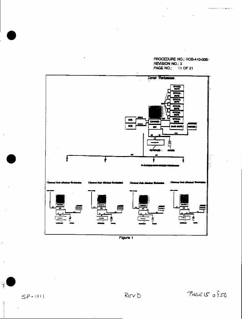
PROCEDURE NO.: ROB-41o0oO6. REVISION NO.: 3 PAGE NO.: 110OF21
. -17
Figure 1
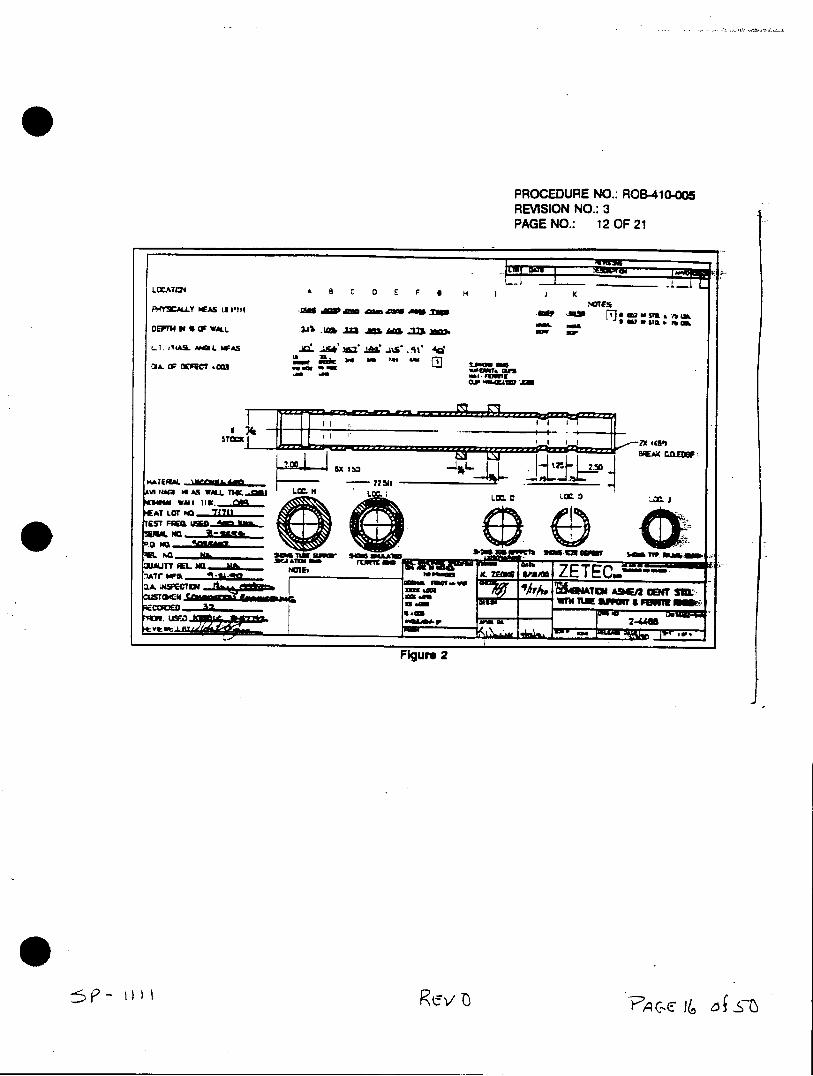
PROCEDURE NO.: ROB-410-aas REVISION NO.: 3 PAGE NO.: 12OF 21
LCCATL24 A a 0 E F a H I K
OWL~~~ M& 9 , : i S a-b
Ll.T i4S AMM WFAS IJI ' Ma7 AAA . Is* -11 Ad_
0A O WC OET OU&'a .0iw u1s "I- "3=9L
OW-6MI U
~STC Mx 045.)-,' _ _ _ _ _ _ _ _* USAn
F~gure 2
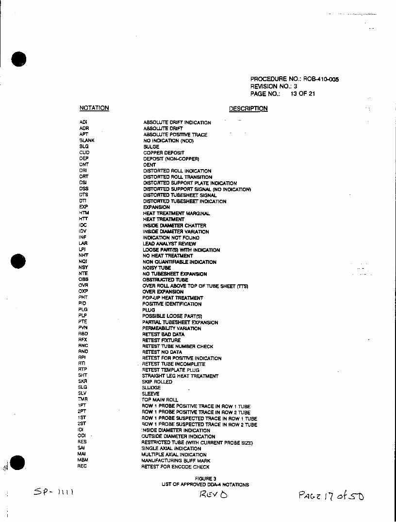
PROCEDURE NO.: ROB-410-)5 REVISION NO.: 3 PAGE NO.: 13 OF 21
NOTATION DESCRIPTION
ADI ABSOLUTE DRIFT INDICATION ADR ABSOLUTE DRIFT APT ABSOLUTE POSITIVE TRACE BLANK NO INDICATION (NDOD) BLG BULGE CUD COPPER DEPOSIT DEP DEPOST (NON-COPPER) ONT DENT DRI DISTORTED ROLL INDICATION OT DISTORTED ROLL TRANSITION oSI DISTORTED SUPPORT PLATE INDICATION DSS DISTORTED SUPPORT SIGNAL (NO INDICATION) DTS DISTORTED TUBESHEET SIGNAL OTT DISTORTED TUBESHEET INDICATION EXP EXPANSION HTM HEAT TREATMENT MARGINAL HTT HEAT TREATMENT 1DC INSIDE DIAMETER CHATTER 10V INSIDE DIAMETER VARIATION INF INDICATION NOT FOUND LAR LEAD ANALYST REVIEW LPI LOOSE PART(S) WITH INDICATION NHT NO HEAT TREATMENT NOI NON QUANTIFIABLE INDICATION NSY NOISY TUBE NTE NO TiJBESHEET EXPANSION OBS OBSTRUCTED TUBE OVR OVER ROLL ABOVE TOP OF TUBE SHEET (TTS) OXP OVER EXPANSION PHT POP-UP HEAT TREATMENT PID POSITIVE IDENTIFICATION PLG PLUG PLP POSSIBLE LOOSE PART(S) PTE PARTIAL TUBESHEET EXPANSION PVN PERMEABILITY VARIATION RBD RETEST BAD DATA RFX RETEST FIXTURE RNC RETEST TJBE NUMBER CHECK RNO RETEST NO DATA RPI RETEST FOR POSfTIVE INDICATION RTI RETEST TUBE INCOMPLETE RTP RETEST TEMPLATE PLUG SHT STRAIGHT LEG HEAT TREATMENT SKR SKIP ROLLED SLG SLUDGE SLV SLEEVE TMR TOP MAIN ROLL 1 PT ROW 1 PROBE POSITIVE TRACE IN ROW 1 TUBE 2PT ROW I PROBE POSITIVE TRACE IN ROW 2 TUBE 1ST ROW 1 PROBE SUSPECTED TRACE IN ROW I TUBE 2ST ROW 1 PROBE SUSPECTED TRACE IN ROW 2 TUBE IDI INSIDE DIAMETER INDICATION 001 OUTSIDE DIAMETER INDICATION RES RESTRICTED TUBE (WITH CURRENT PROBE SIZE) SAl SINGLE AXIAL INDICATION MAI MULTIPLE AXIAL INDICATION MBM MANUFACTURING BUFF MARK REC RETEST FOR ENCODE CHECK
FIGURE 3 UST OF APPROVED DDA-4 NOTATIONS
R4- )iMI
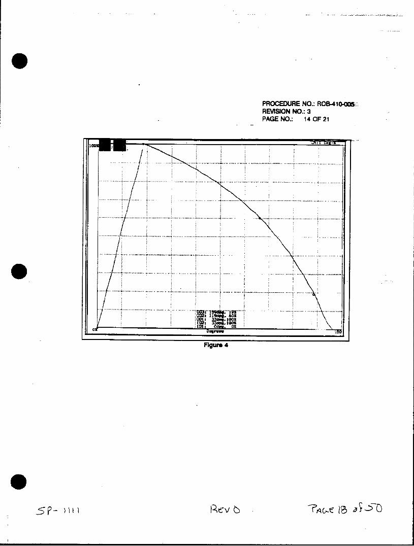
PROCEDURE NO.: ROB-41O-aO5-REVISION NO.: 3 PAGE NO.: 14OF 21
..~~ ~ .. . .. . . . .. . . . . . . .. . . . . . . . . . . . . . . . . . . . .. . . . . . .. . . . . . . . . . . . . . ..
........ ~ ~ ~ ~ O~ ................................. .. .. .......................... .. ... ..........
.....~~~~~~ ~ ~ ...... ..... ....... ....................... ........ ... .
............... 001 ........................................ .. .. ................. .......
............... 101 ........... ... ....... .... .... ......... . . ... . .... . . .. . . ... . . .. . . .
.. ~ ~ ~ ~ ~ ~ ~ ~ F g r ......4. ...... ....... .. ....... ..
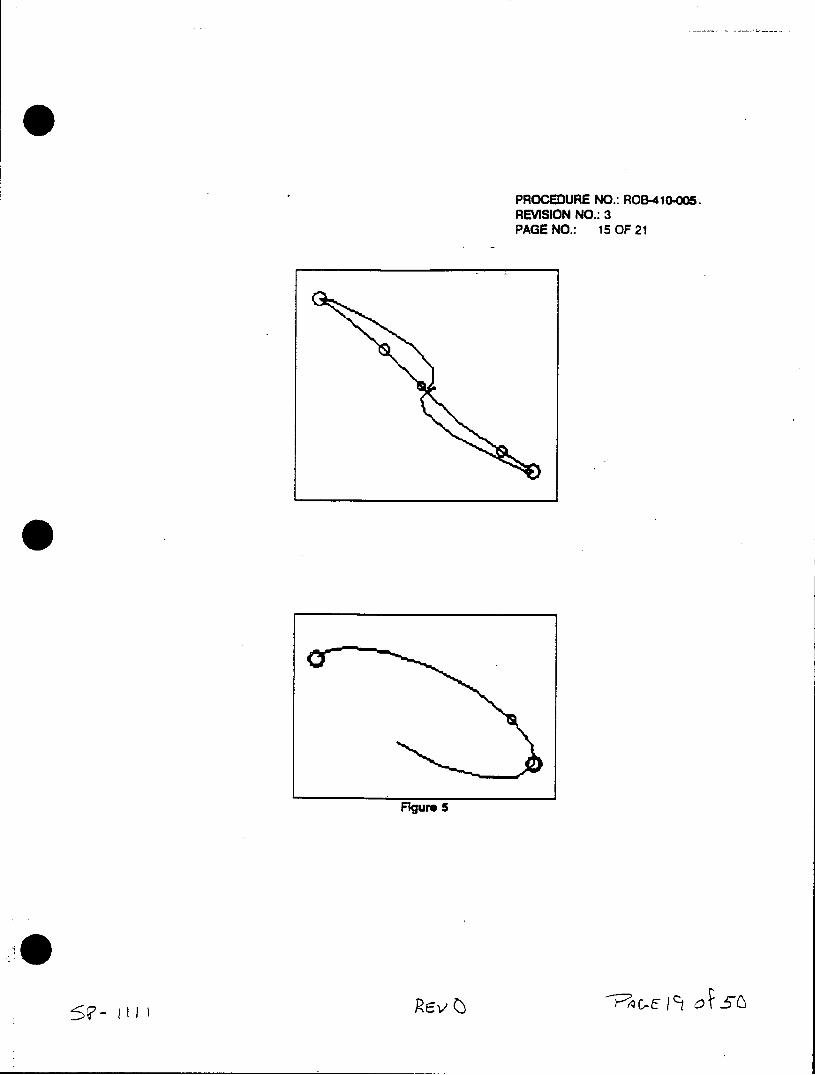
PROCEDURE NO.: ROB-410-005 REVISION NO.: 3 PAGE NO.: 15 OF 21
Figure 5
ReeJc
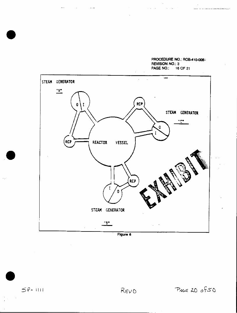
PROCEDURE NO.: ROB-41(05-oo REVISION NO.: 3 PAGE NO.: 16 OF 21
STEAM GENERATOR
"A*
0 I RCP
STEAM GENERATOR
0 STEAM GENERATOR
Figure 6
0
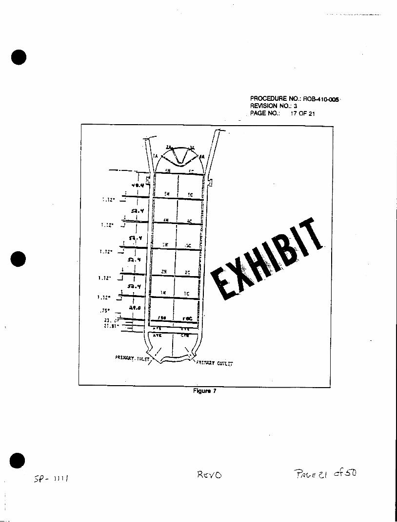
PROCEDURE NO.: ROB-41o-o0 REVISION NO.: 3 PAGE NO.: 17 OF 21
IAA
1I~.12f I l.*
1.122
laIC
21 .31"
T/
Figure 7
* 2. )I
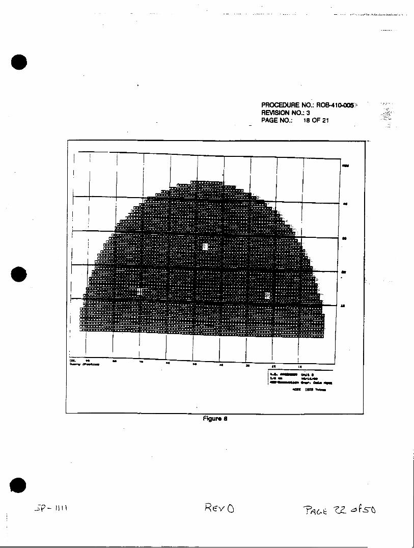
PROCEDURE NO.: ROB-41O-MO6UREVISION NO.: 3 PAGE NO.: 18OF 21
cm to .0
40110101 WAS R4
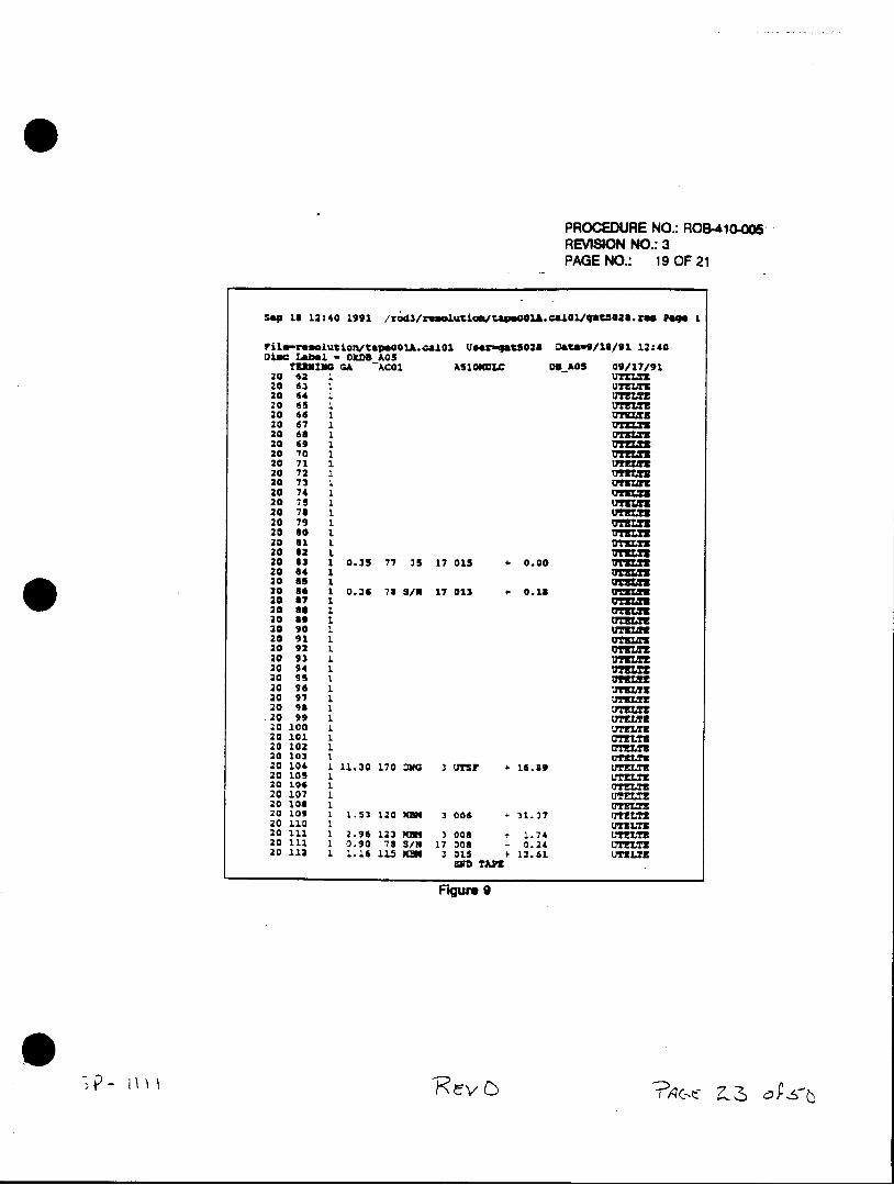
PROCEDURE NO.: ROB-410-oos REVISION NO.: 3 PAGE NO.: 19 OF 21
Sep 1$ 12:40 1991 /rog3/ru1oltl~ta.01AC&101qat50GZ.US Paqe 1
FiI.-resolution'tapooo1A. calol Usar-qatgo2S Datswo/S//9 1 12:40 Di8C Lab.l 0 kDSP.05
TUING GA -ACOI AS1OIWLC DVRAOS 09/17/91 20 62 1 UTZLTE 20 64 2. UTZLTI
20 65 2.tTELTZ 20 66 2.07=BJ 20 67 1 3.T 20 03 2. 0TZLTE 20 69 1. UTZ= 20 70 1. mIXZ 20 71 1 UTflzr 20 72 . n z 20 73 1UZ 20 74 1 T= 20 79 1 (IUIWU 20 76 1 UE 20 79 1 UTZ=X 20 80 1 UZ 20 31 1 OE.T3 20 62 1 M 20 63 1 0.35 77 35 17 015 0.00 V= 20 64 1 rm
20 3 1 0.26 78 S/N 17 013 . 0.28 vTL! 20 87 1 DZZ 20 33 1 G'lT 20 33 1 UTZ= 20 90 I. UTII 20 91 1 UZC 20 92 2. u?31 20 93 1 .B 20 94 1 UTTE 20 95 1. UYTRM 20 96 1 Lmint 20 97 2.~fLT 20 93 1 UTZ=T
.20 99 1 UTELYS 20 100 1. UTELTZ 20 101 1. =T!L 20 102 1. =TUx 20 103 2. UTZ.T3 20 106 1. 11.30 170 =NG 3 UTS? 16.89 UTEL?3 20 105 1. LFZLTZ 2010 IN TLTZ 20 107 U3. 20 109 . 1.52 120 NUN 3 006 - 31.37 UTELT2 20 110 1. UTELTZ 20 111 2. 2.96 122 MMI 3 006 1.74 LT!LTZ 20 12.1 1 0.90 71 SIN 17 006 - 0.24 UTELTZ 20 112 1 1. 16 115 KME 3 015 + 13.6L UTULTZ
EID TAMS
Figure 9
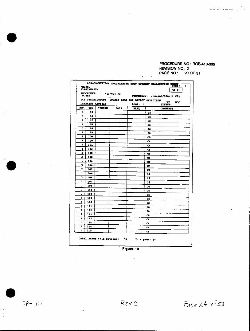
PROCEDURE NO.: ROB-4104Mo REVISION NO.: 3 PAGE NO.: 20OF 21
ADS-COiMMUMMC USGIUUUiNG g~y aim~ nML2MIfCg Si
PL&W1/ WI!?
PROM MRmuS 410-004 R2 MalBE ________ ?lo2icT 4Q0/o00/I00/10 Usa
C? D2S3ZTZ0U: sOOSxf Xm 101 DzTZcT CT1CTWI rAC: NOT DATMFri ADD"=~ ZONst 2 XUY
3 94i C6i A? E
2 97 L cd 1 96 cd
:2 go _ _ _ICd
2 92 ___ _ c 3 100 1-s
___ _______ ____ C6
3 102 Jca 2 103 . _ co 1 104 C
3 104 cis
32107 cs 2 107 c
2 109 _ __ __
-1-Ila C6
1T ~ V _ 1- ci
-0tal ~Mc thin Datame%: 30 Tb~s pinquz 30
Figure 10

PROCEDURE NO.: ROB-410-a05 REVISION NO.: 3 PAGE NO.: 21 OF 21
C-E ET LEVEL 111 DATE CUSTOMER REPRESENTATIVE CONCURRENCE DATE
Attachment A Data Sheet Documenting
Customer Specific Data Analysis Requirements -p- uuv-s-6s
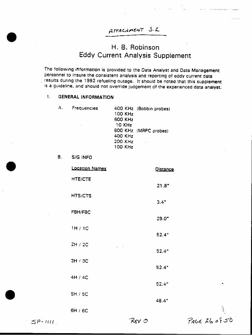
H. B. Robinson Eddy Current Analysis Supplement
The following information is provided to the Data Analyst and Data Management personnel to insure the consistent analysis and reporting of eddy current data results during the 1992 refueling outage. It should be noted that this supplement is a guideline, and should not override judgement of the experienced data analyst.
1. GENERAL INFORMATION
A. Frequencies 400 KHz (Bobbin probes) 100 KHz 600 KHz 10 KHz
800 KHz (MRPC probes) 400 KHz 200 KHz 100 KHz
B. S/G INFO
Location Names Distance
HTE/CTE 21.8"
HTS/CTS 3.4"
FBH/FBC 29.0"
1H / 1C 52.4"
2H / 2C 52.4"
3H / 3C 52.4"
4H / 4C 52.4"
5H / 5C 48.4"
6H / 6C
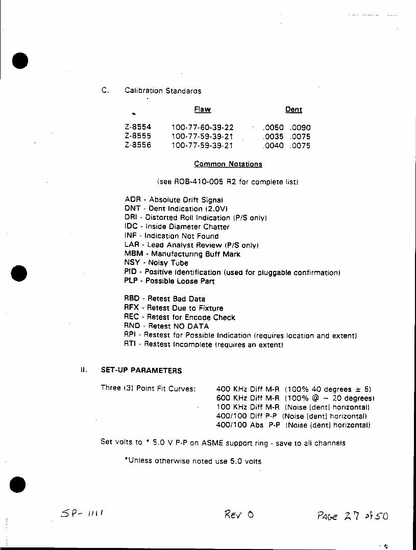
C. Calibration Standards
Flaw Dent
Z-8554 100-77-60-39-22 - .0050 .0090 Z-8555 100-77-59-39-21 .0035 .0075 Z-8556 100-77-59-39-21 .0040 .0075
Common Notations
(see ROB-410-005 R2 for complete list)
ADR - Absolute Drift Signal DNT - Dent Indication (2.0V) DRI - Distorted Roll Indication (P/S only) IDC - Inside Diameter Chatter INF - Indication Not Found LAR - Lead Analyst Review (P/S only) MBM - Manufacturing Buff Mark NSY - Noisy Tube PID - Positive Identification (used for pluggable confirmation) PLP - Possible Loose Part
RBD - Retest Bad Data RFX - Retest Due to Fixture REC - Retest for Encode Check RND - Retest NO DATA RPI - Restest for Possible Indication (requires location and extent) RTI - Restest Incomplete (requires an extent)
II. SET-UP PARAMETERS
Three (3) Point Fit Curves: 400 KHz Diff M-R (100% 40 degrees ± 5) 600 KHz Diff M-R (100% @ - 20 degrees) 100 KHz Diff M-R (Noise (dent] horizontal) 400/100 Diff P-P (Noise (dent] horizontal) 400/100 Abs P-P (Noise (dent] horizontal)
Set volts to * 5.0 V P-P on ASME support ring - save to all channels
*Unless otherwise noted use 5.0 volts
C2.
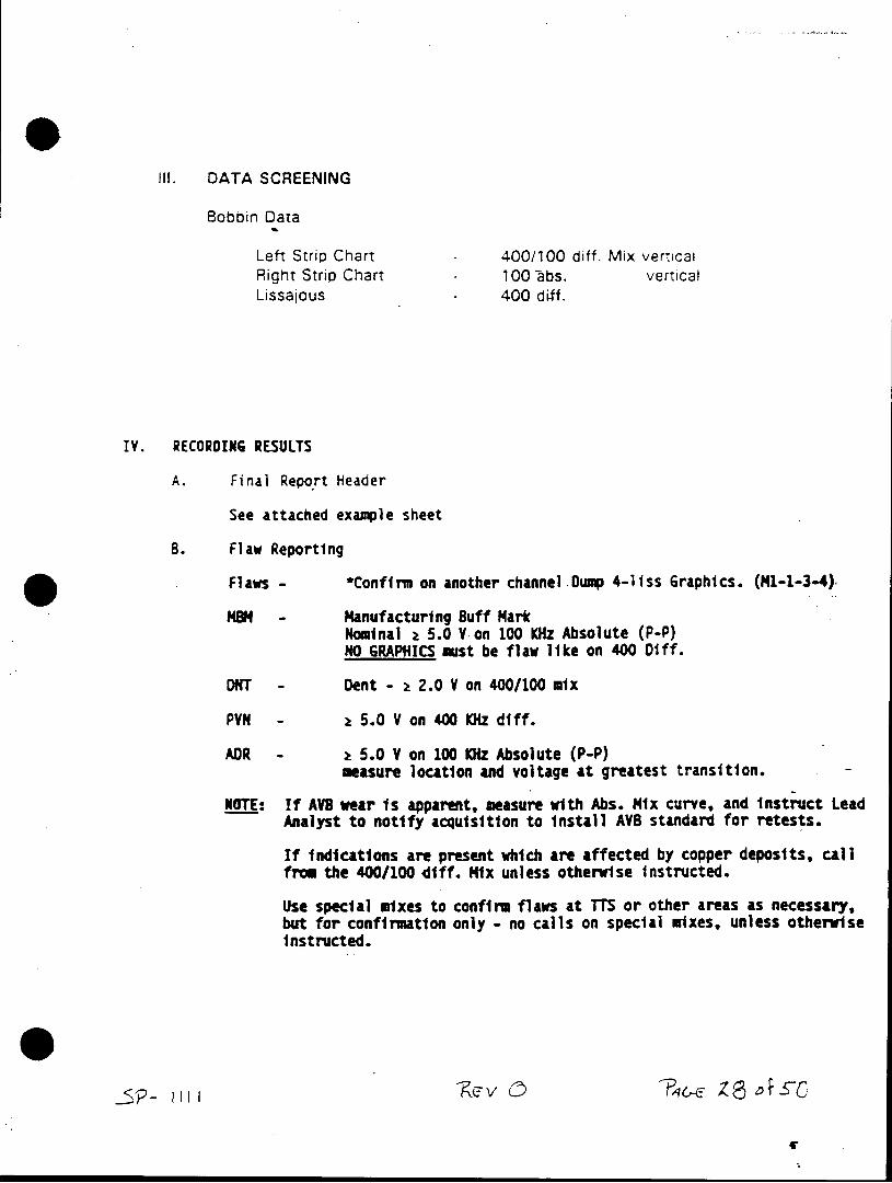
Ill. DATA SCREENING
Bobbin Data
Left Strip Chart - 400/100 diff. Mix vertical Right Strip Chart - 100 libs. vertical Lissajous 400 diff.
IV. RECORDING RESULTS
A. Final Report Header
See attached examle sheet
B. Flaw Reporting
Flaws - *Confirm on another channel Dump 4-liss Graphics. (1-1-3-4)
MSN - Manufacturing Buff Mark Nominal a 5.0 Von 100 KHz Absolute (P-P) NO GRAPHICS must be flaw like on 400 Diff.
DNT - Dent - 1 2.0 V on 400/100 mix
PVN - z 5.0 V on 400 KHz diff.
ADR - z 5.0 V on 100 KHz Absolute (P-P) measure location and voltage at greatest transition.
NOTE: If AV8 wear is apparent, measure with Abs. Mix curve, and instruct Lead Analyst to notify acquisition to install AVB standard for retests.
If indications are present which are affected by copper deposits, call from the 400/100 diff. Mix unless otherwise instructed.
Use special mixes to confirm flaws at TTS or other areas as necessary, but for confirmation only - no calls on special mixes, unless otherwise instructed.
-KsP- V PllC-'
D. Graphics Printout
First graphic
Reporting Channel (400 KHz diff)
Second graphic
Multiple LissiStrip Charts as applicable
5 P - '-R E
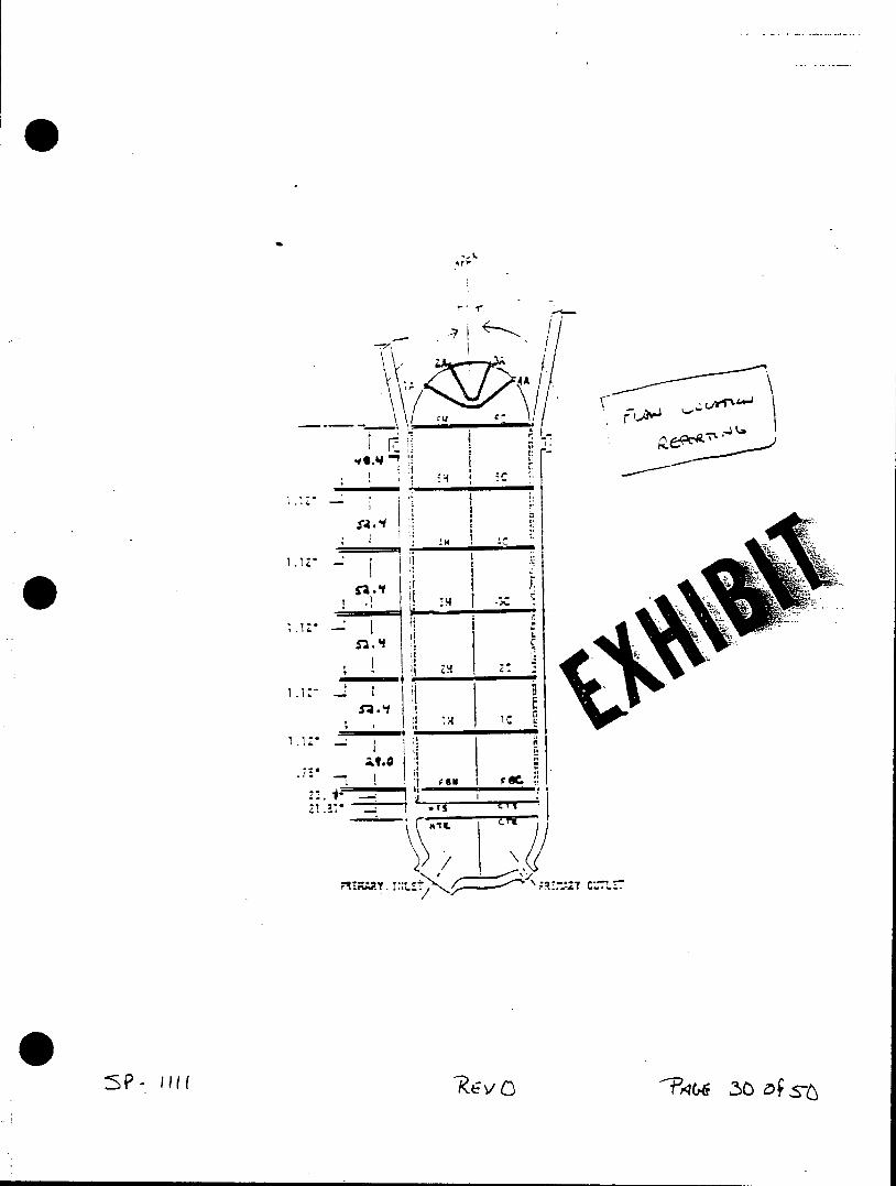
4A1
- a I
.1z,
7
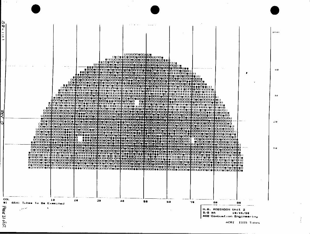
13* Dil~~ol00000300 onnLo 0301011001noi
1111100 U 000113 0111111001311013 30 0 00 a o .uouooOno 0m0ooo 00000U~
finaist)ofi on Vffntimnn snonnnuII osn n n ni nI f ]1 noi nn i''1
(10110" s oono qJ,11I0,1jgIooou(u 1O1g~g 1511011g INOD00 000001000003 O 0ooe0033000O1 00 03E000 30030000 LonslO onil ogag " ooo, 00 (110110"01 2"sp oo 1noo llU al
alonoons * 011110000030 0300omn *n0v 130 f 0a30300001 oo lo 0000*000300 oniimii 3311301300* l~iflIon 101131 6IO nhn unnnonnlI I nnru ini 1-1i soonono atm 11 lle figll 11111 1313UJ 101111l1la 011l iu 11ggggJ .glnlgjan1i llD111111 g01"( W1g1 g 11fil o1 11 11111111111 101 11111111131.
0 ousua1s13111 11110010011110 00013i 011110JlSg 11 1013 11 111111000 11311100000 I 0001(111111 ounnuf 000 00000000 sOooouoo OOOOO3u 0031MV (303330 300000000 03000oo0gon oaaso O0000 "Da no n 00011000011 0000031 13~ gao 3013100011111 9o0o3uo3o: 0111110413100000300 0001111300D
Ul030 0030 n owon 0000000ooooo Doooogooa~oon 0000000000003003000n 000003 u0000ognaaaa 0Do0u30o000033 0000000300000 00000OOOg 000000nai aOOOOOOon
00300 w 000 03330 0003 0000 0g003 00 ?0 000303 0 00 0 0 11 3 03 0 0 1O~ o~ 0 3 0 0
0 3 3 3 3 0 0 0 3 0 3 0 3 0 3 0 1 3 0 0 13 Cg o 300 0 0 I 0 0 0 0 0 0 0 3 0 glooo~ 00.eo:00330 003030000000 11000000041 00100010300001300100 ge00001vnnoe 33000300 0003000 000030300 GI3003003 3 00 0 0 0 00 030000300000 qiiind a0000 0030003009 000300301 8180000 0000000 OOO0oooc 0000000 013800000J 003000000n orna~nonfa1130000o
0 0 0 ( 0 0 0000g300 anoa 100030330 fsgfnonfon 000030330 Donnooons*~
000000000 030IgO03 003000000 en 000 300000 300000030 000003033 000000000 01 03000011 33 0000C109ofoooouoou ONDI0u0o0 0000003100010033 111030300 00000000D 000030303 0 u0111110 11 0 00301100o 333000000J 0 0110 (103 0000 130 0 0 3 0 0 3 0 0 01000 100 0 0
COL 16 20 30 40 G 6b 70 be IDS : 654 : Tu bes To B . E x fm n end [ . . R B I S N U i
5/-0 VA 10/16/90
A818-Combuut ion ElgineerjnU
ACRI 1515 T~aiie
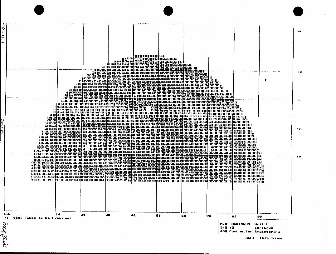
Il ii AI
0s3033uwq00000006 000 anosO~ 00
oooa0 10*1oo oo. ____ -osooosogauo3111 000osoaogoso 0413001313 00000110100
one 030000 0000 fOOOO DOoOGOo 00.003830 OOggO O 0000000000 30300000 303000 ODOO #001 013 ooo 10133000000 uSD000nva 0000011111111gO DOO1eg 00000000 OOOflODOO Dan UIOgon ouso nfonogno nuoosonanmagnncoonnnowo nngofoisf
g000 D ao o00S00U0o NO00000 OO03OOD 0000000 00003 000000000 is a iiii a ia ia u aroia a asan Ia g a ain onaanowri Ilgesiong a 0nnw aiimaae asgjaag nno aalg ut t
0il000a *O~lf~ O OflI3000 aoflil ofln noogonvn oo onbnoon 001annlgi 1011rnvoairio (grnaaI floo ~ngo4 00000 ODO 0000000 uosiooo Oogooasoogooono, Dammam 03000
L1 OO 33000000 11103013111030 Gvog00g003303003g0 MOOOUOOgOOD jOODODOgoODOOD
1103000 30000008a111108o11001300 30110000g0 OaGODDOOn 'J00006n*0 00030030000300 OOOoonOO 003030003 00030 0 178 on0n 0030033 On 300 Do030n 2 2 4 000000 000300000isnos 0000 000 0003 000 0000 000 0000 000 .Oao ooa 000 0003I ~3 g00s 0g00 0030 0 OOOJgOOts
000030030 0000 003 000030303 ODDDb11110003030 10 0 *111001011 OOOOO1111111300000 0 110103 nocon Ooooo 000000000~oo 00000 V0 sn00000000 0usgOOqI v08,10001 O oiOlgo 030 000900030a30 ng~l aouoo 0,0033000 6Oesranqooooo 30300000 3 00sile
000011010 300000003 000030003 0 0 0 0 :00 0 01003011108 00100000010OO0gOOOag 000g000 noil003000000 0 Onog0lonj0000003OD00 000003000 Goon DODO 004ooomooso6001 300000 0 030005g000013013 0011113n a33 genaa agg rimnnnrjnauihnn 08001303130 n00113301 011nnnnonrjn17 0flg 00flfffe fll0S0flhff00 000 011 SfifOD~lolifigffl(
COL 1 as 0 4656 6 3 89
G ~ 38 16 16
or-Cmb~ Eo En nGrn 32DI aSI aLb
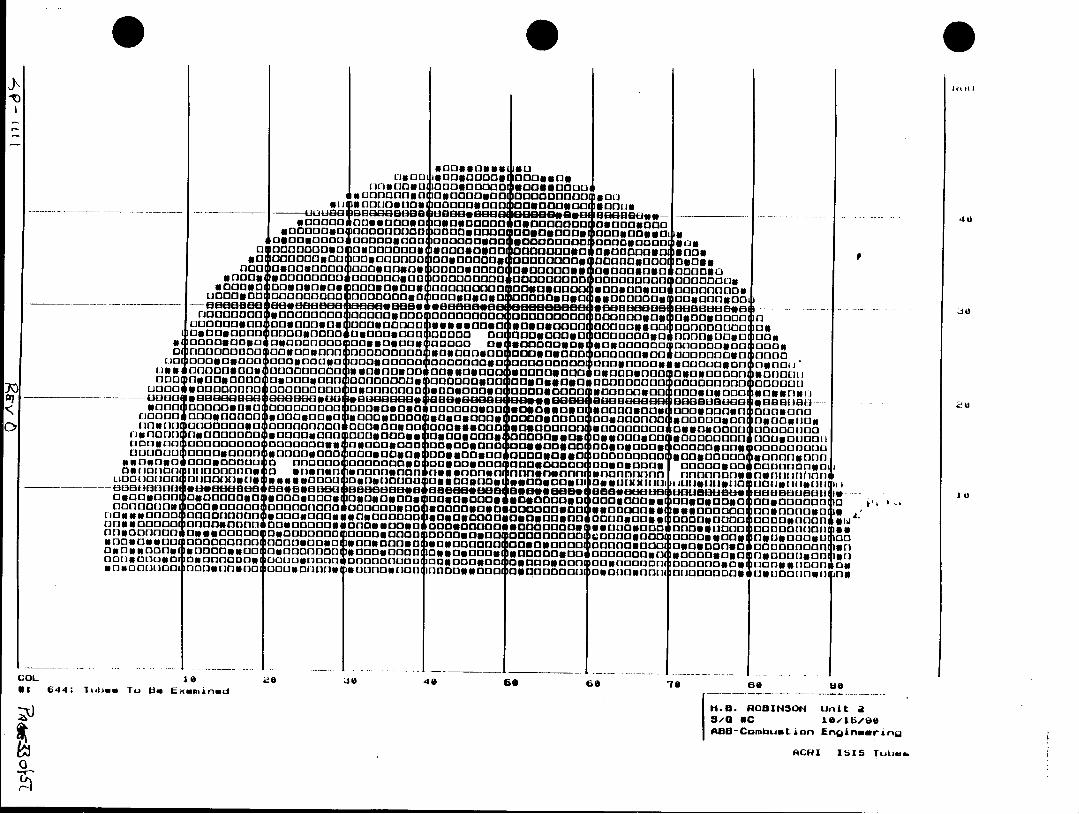
3003033633 L ~ ~ ~ 00*0u8 30300 Og0
*000000Go0 0300u0 000 00000 000 31 ~3~o VOO 0000300*00300000601 UAOODOD ho
so00a 0a 0a 0 010 13110300000 03000000011E]31w 0I30003000 34 110 1011111 OOon1030 C000030000200u03DO003 000*00n* C13133 0 o13s NOODOOOD 0300000030 ooeOO iOODO ODOGUDo 01310010000 3003OLI VOOOODO(*[0000 CIRS(30113 qloomoooooo 003000003131 60oooo.000000 03g0310O DOODOD DOOODOuIoo 13313 3003#0 aOoIElouooo113o3Ooo. 003030 000000ODOO 00018 E013 080 EN0030RR *100000000 00000000 000000000e 00000006*3 --01300303 0030303011 1313soo 00830DOOE3000000310 DOGWOODSo unowoosno0 oooo
010330003 00183003034 33333ODONo 0000 *(03030000 000003300 000000000 03 0303000 000030000OOOgOO 0000D 00 GOODOOIO 0000000000003 000303 0n0000va3030 00000oo 03gagn 3000030 303000000R 000003 00000 003003000 n3Q0000000 303000300nsono 0003000a 000030 00000003 0000 D 0 0 0
j00000000 q000000030 00030030 0000003 *e0000003 003000300 I.)0*303000oo 000000 0000001100 00s"u 10000000 000000000 0 8 00000000 030011l 00000 00000 0000433303003D000003303000ODO 300003000 030Dnunon 0000000o 300001 DD:.O30 O ODO D0IJ10000000g4300000000 000000oWOOODUDOo 0000000003 000001: -- -- -- fqE0 60886" 8080 g *8UGB888O BaB*696g 1830008 9888808 08898me3J oo88f6u93---ono ioono o lo 0000000 000303030 o *0000000030033 o3000r30315003000 noonoi
f00004300003 000000*0 000300000 33000 0000000 300000000OOD~nO 0303000 00000(100" 00000 000300000 3 0000030 0000000F'0800000300 03000S61030000 owO 3w00000gou. nogaluZItg
00000 0003000 sOD~gOD ~00303030030000 00000330 O0OODOOO 0300010000 330303 300030 00 0 0000 000 p00000003 0 0 60 0 000 0 00 600 00 0 00 30 8000 " I 00 03 0 00 00 03
0003000003000003C30030003 33000000000 038O000g 0000033 03303C:030000.0 0000000 00000000*00000 a0000~003330000 33000003 333000000o 003000030 oncI Do On if B uBUf 00 3 8 1318368 E1808 368 i 8a 88 a~~ aa e e. . 6 0 888 0 tIF jl 10 u t t e * 0 i8 U B 110818080 00000000 30 03 00 33 30 00 0J03 30 00 03 30 30 00003003gU 003 01 0 0 0 0 3 b
oriooooooo oooo~~~SOOoooe 00300300u0000000300034300030008 00030000 00000000(1433 003000000 1 03300000n 030000043000000 000030300 0000004 (00000 000303033000q 3003r03 000000OO on000300304*300S00030 300000 nO O003000000000030 030300030 0000000004330Mll s 030330003 300003300 030000081000000 3000 D000030000000u 300003030303000030onsnow001 000300030~ nll(331 030000003 0000 0030000000 003000300 030003000 noouOOOOo 0000003034300033(3000go 030(10000000 00030(10D 00003000 0000 03000300 00000003330001031 03o~g ivonolo
COL le iejo 40 536 0 so Be
33 644*: 'ktins u He i Exmnad
1.U. RODIN30H Unit 2 a5,0 OC 10/15/Be
A88-Combust ion EnginwwrinW
0 ACHI 1515S Tuhmu.
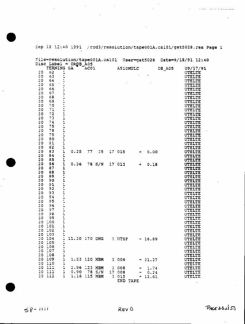
Sep 18 12:40 1991 /rod3/resolution/tapeO01A.cal01/gat5028.res Page 1
. ile=resolution/tapeOOlA.cal0l User=gat5028 Date=9/18/91 12:40 Disc Label = DkPBA05
TERNING GA AC01 A510MULC DBAO5 09/17/91 20 62 1 UTELTE 20 63 1 UTELTE 20 64 1 UTELTE 20 65 1 UTELTE 20 66 1 UTELTE 20 67 1 UTELTE 20 68 1 UTELTE 20 69 1 UTELTE 20 70 1 UTELTE 20 71 1 UTELTE 20 72 1 UTELTE 20 73 1 UTELTE 20 74 1 UTELTE 20 75 1 UTELTE 20 78 1 UTELTE 20 79 1 UTELTE 20 80 1 UTELTE 20 81 1 UTELTE 20 82 1 UTELTE 20 83 1 0.35 77 35 17 015 + 0.00 UTELTE 20 84 1 UTELTE 20 85 1 UTELTE 20 86 1 0.36 78 S/N 17 013 + 0.18 UTELTE 20 87 1 UTELTE 20 88 1 UTELTE 20 89 1 UTELTE 20 90 1 UTELTE 20 91 1 UTELTE 20 92 1 UTELTE 20 93 1 UTELTE 20 94 1 UTELTE 20 95 1 UTELTE 20 96 1 UTELTE 20 97 1 UTELTE 20 98 1 UTELTE 20 99 1 UTELTE 20 100 1 UTELTE 20 101 1 UTELTE 20 102 1 UTELTE 20 103 1 UTELTE 20 104 1 11.30 170 ONG 3.UTSF + 16.89 UTELTE 20 105 1 UTELTE 20 106 1 UTELTE 20 107 1 UTELTE 20 108 1 UTELTE 20 109 1 1.53 120 MBM 3 006 + 31.37 UTELTE 20 110 1 UTELTE 20 111 1 2.96 123 MBM 3 008 + 1.74 UTELTE 20 111 1 0.90 78 S/N 17 008 - 0.24 UTELTE 20 112 1 1.16 115 MBM 3 015 13.61 UTELTE
END TAPE
6?gH
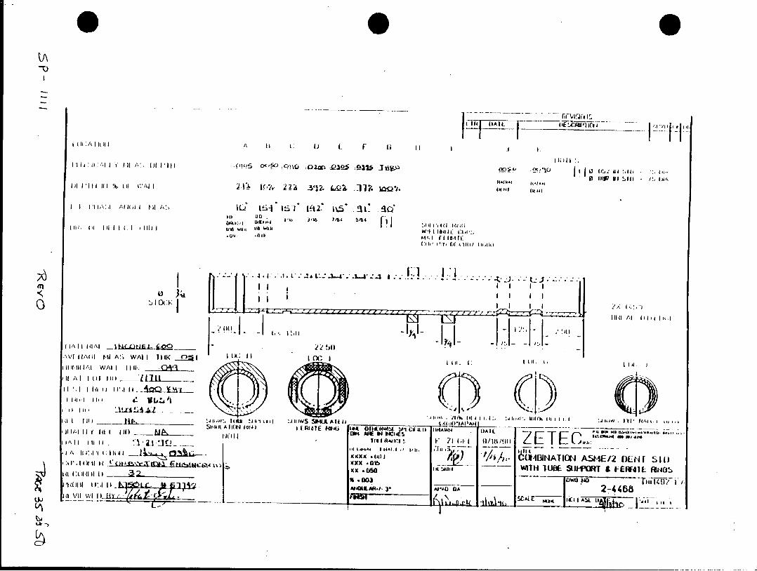
iF II
I t (I ill I Al1~1 H L ~ I i 1i. is
*o, tlI fl p . 01 ,1 *Oc, LX.l ol w-,of ,
'~"^ ii I
Rill I vi d lv t
Al/, ill I) I r 22~l 116 " t V MwO al ' \V(~~~~. " HAl MI A A I a1K~I C. 1 H Hti l
IIl I. W K Hii H4II/
G - If fi l l
AII I lIl I AS W A I I i~. I- II tIMK I-) I I. I'i i t 1; (it 1/, f 4 3 N T c~1 A tI /
I(1-U1 IJ-PI A£ WAI I IE111. Ill A I 1 01ITR
.003% 1_ __ _ 1wu 49alO SitIiIIiIf o A[l A~t*AA
I~~~~( Ia I 4 ^.I r V !I I . lA Z~ 0/89 Z Lsh ) Ei ,C
IPA--_ _ _ Ill_ _ (I5 11IA11 l 41& ON TO A M / E I
C-)
I TI
__ __ , 1 _ _ _ _ ___31__MCII I 11 11f
__I_ 1.r "pit~ f I IA ry 1___1______ JAI'-~ L II I I~ II 1141 r IIWl, Il
I~~~~~i __ __ NPO I,,v* If10
I 1111 11~v u l W'1(1 , 1) igi0i. if11 M'H>11 Im II o '1\
~~I "Ii If Ni
I I~ II 10 M I I ?,A>IlII I I : S I I I f I A
I . . ?
IF:P11P A1V w .(5im w c 51111. l'?QIII/ SW5 V ( III I I: HI III I
f f I 1'~ -1 7 0~ '. Il-I IIII?'I
VIA~v~ 11[ 7KY 311I~v1~ !IW
F~FFH ~ KIQI
VIII I II' r~t~oA
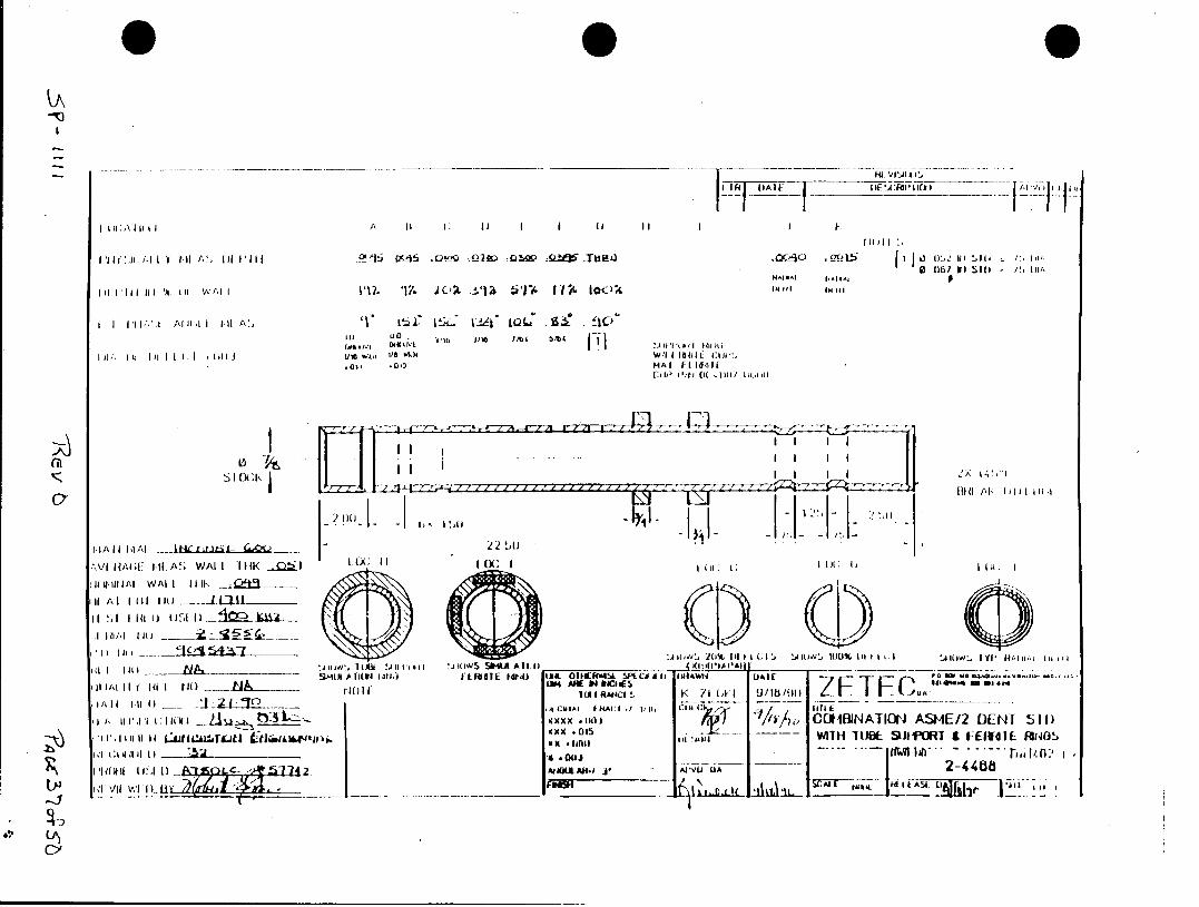
A 1411il1
Ili~ Il~ I (I6 1I S115 lu
'(lA~~~~~d mJ~ NJ 1.1 1: P, Di-A~L~ * IQ
A[ll 1148 1, 1.11tA!
II ii i .l .14111i ie W", 1/B0 4 W'I t 811 C' .i .0,0 MAI Frltofi
Col *i l( WIII)) l 1,11
;(VI A C I-i.A Wi II IM1AIIq IJAIEI ZEC IF C (
I 11 ll A I IM IR I~ It4J it
-l
)A[i
Ij~ I I
Ill.
rQql I'' -_ ------ .- - 1,1Ot12bll ffi li tA3w1 o % j ~ l -A O L _ _ _ _ -I~I Il i
t. W 54-1-
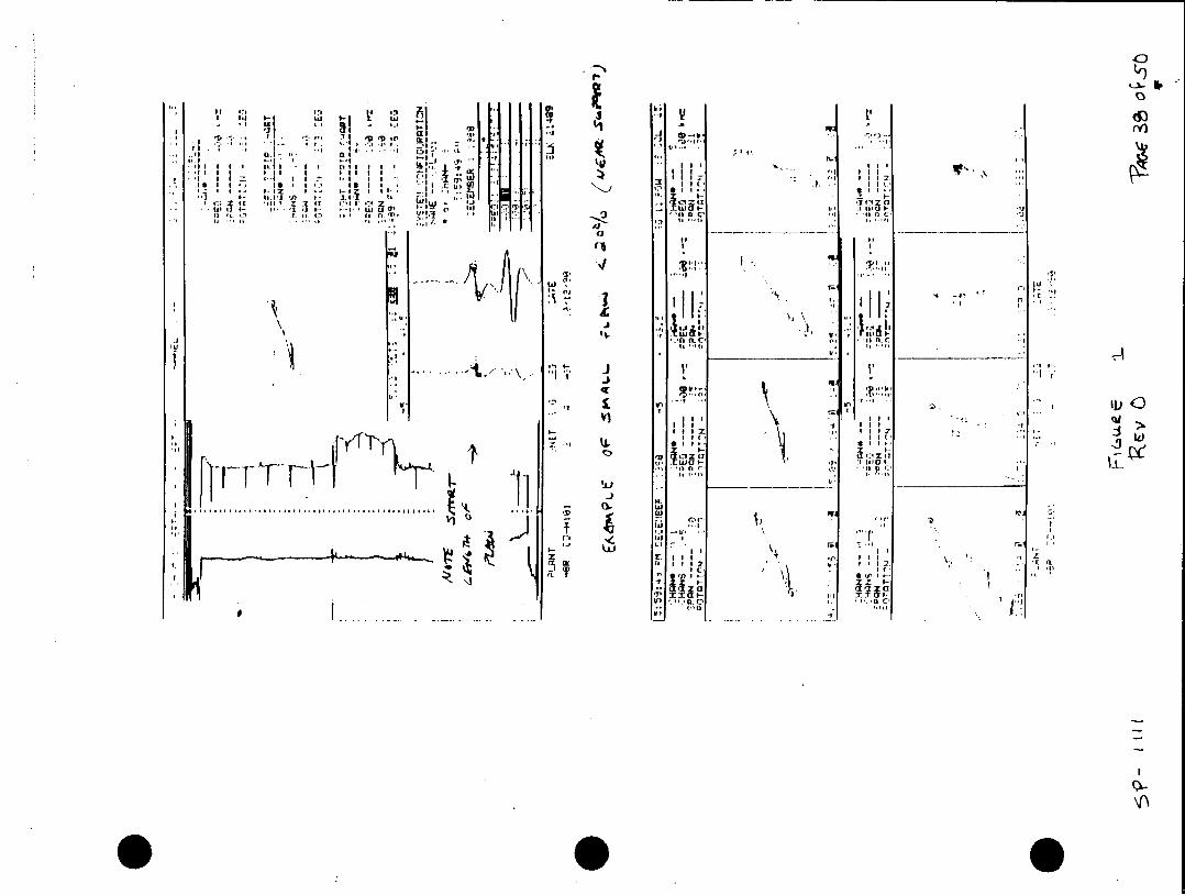
7 zI ,. S I
CS 4
II' 4
- IIr-i I
(1, L o 1 :. D1
I* Ll -P
V) X" I C,1
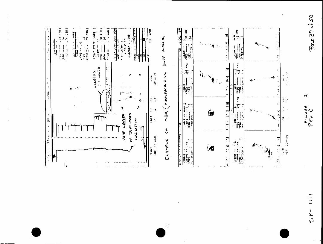
l , Ni N
I"I
to,
C .IL
i.9 . .Ut
I t
ILI
II I ,
4, i:'
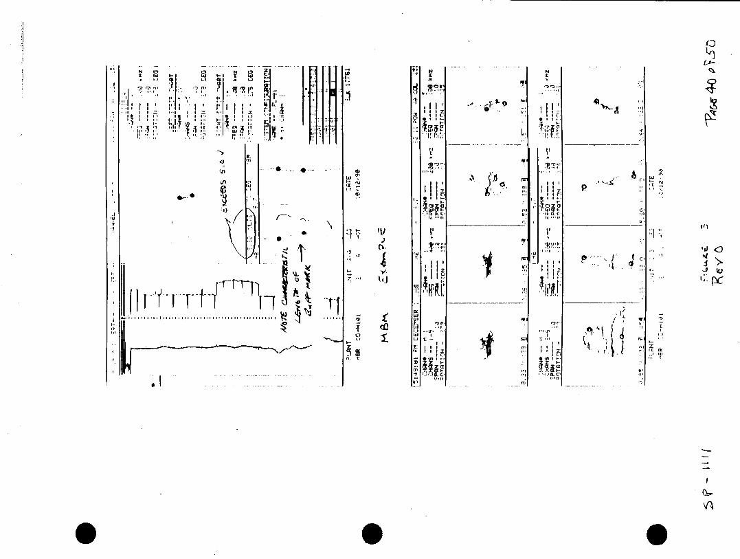
IN)
s I
T. W I- v1 ..
IV
ILI
.. . . . . . . . . .. . . . . . . .. . .. I. r o
CC,
p, 9 , (
J1~F -f 1' __________ i
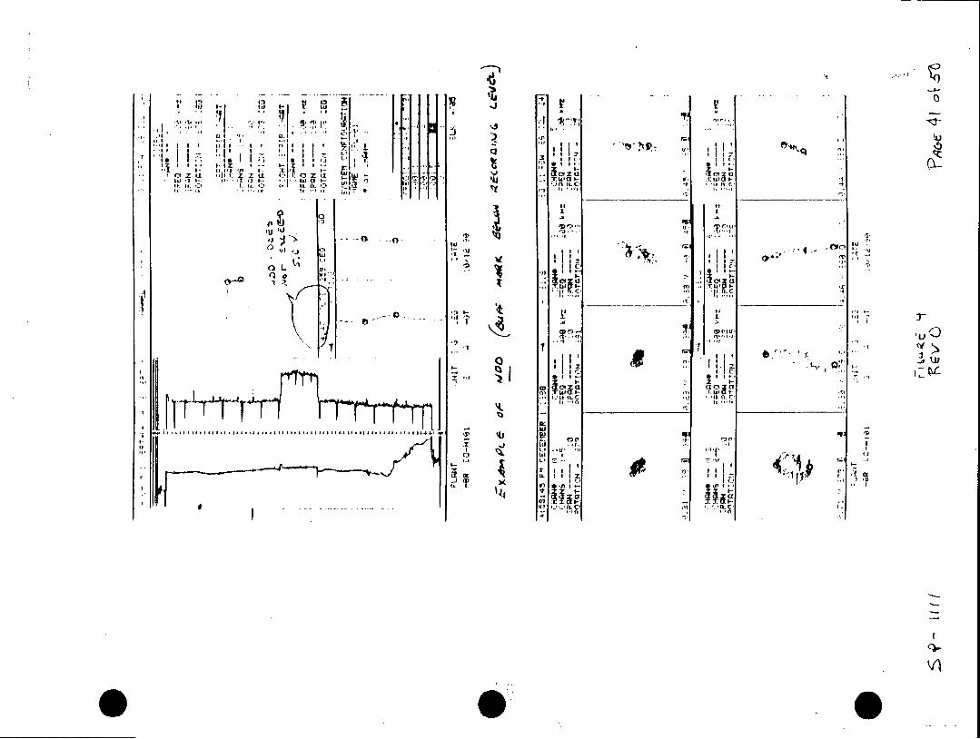
C3 z .I'II I- t:I u
f"I
Ij '1r*
CI a .. CI cx
-l it I.- If
U, ItI
1~U 1 *-t,.'
ILI 'I.1 .. V,' I I2 I zZ:e
ID X
0 i
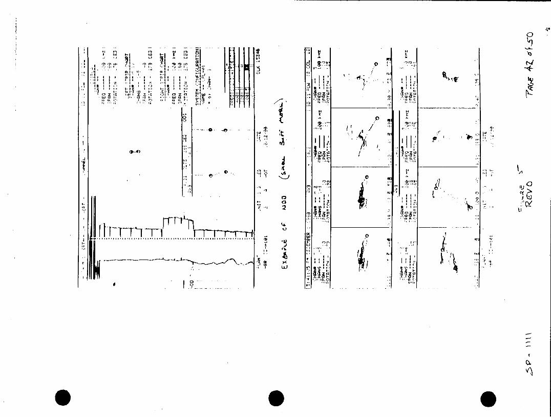
M0
U I I-T w , ri.
z~. I.- t-It9
It Ii(.
SI . ..... tjs
a 4
00
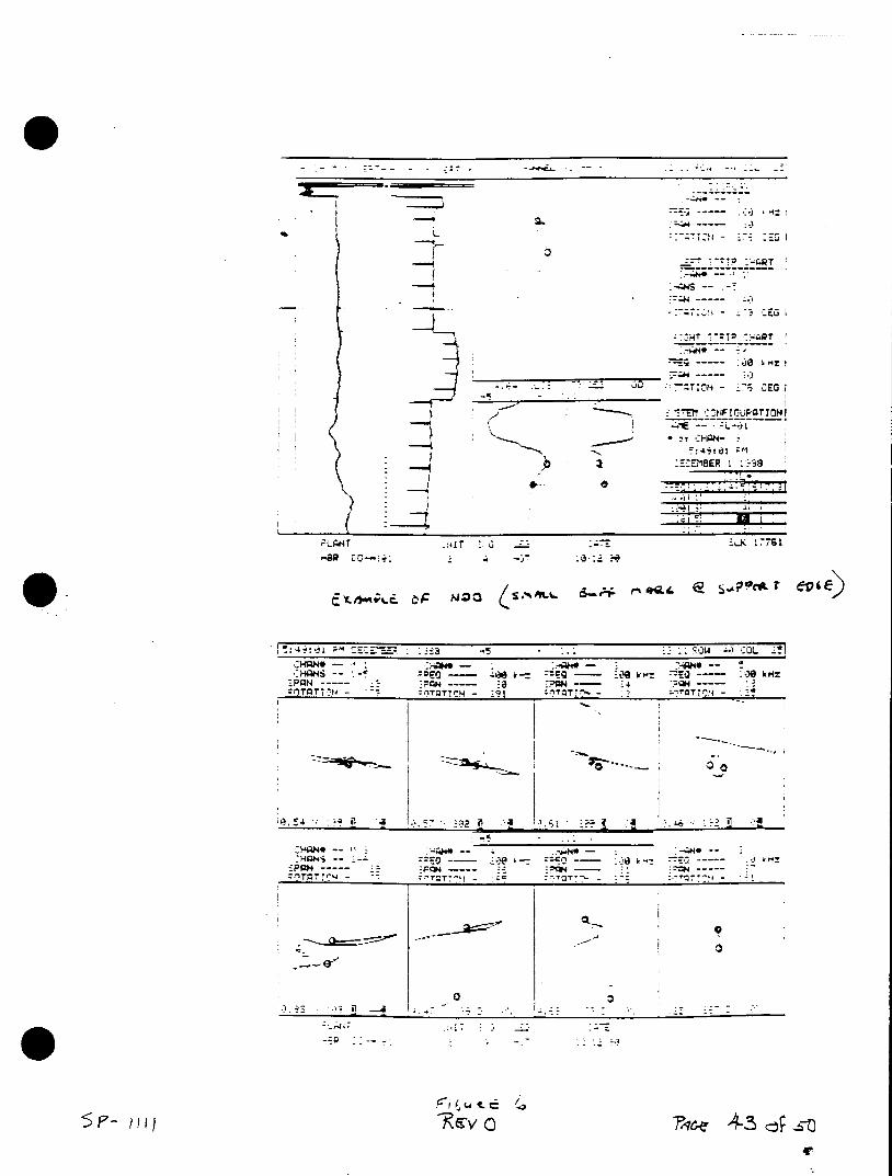
i-l CEO I
1 .3.:-;.i4
-BRO CO-:L. -:!I~
zin :,Do --- i--- m
:1 tT T -T 1
--. -'4----,.
r r n cE - - :9 - :,:
:pQQ
1 T
5P- H)Rv
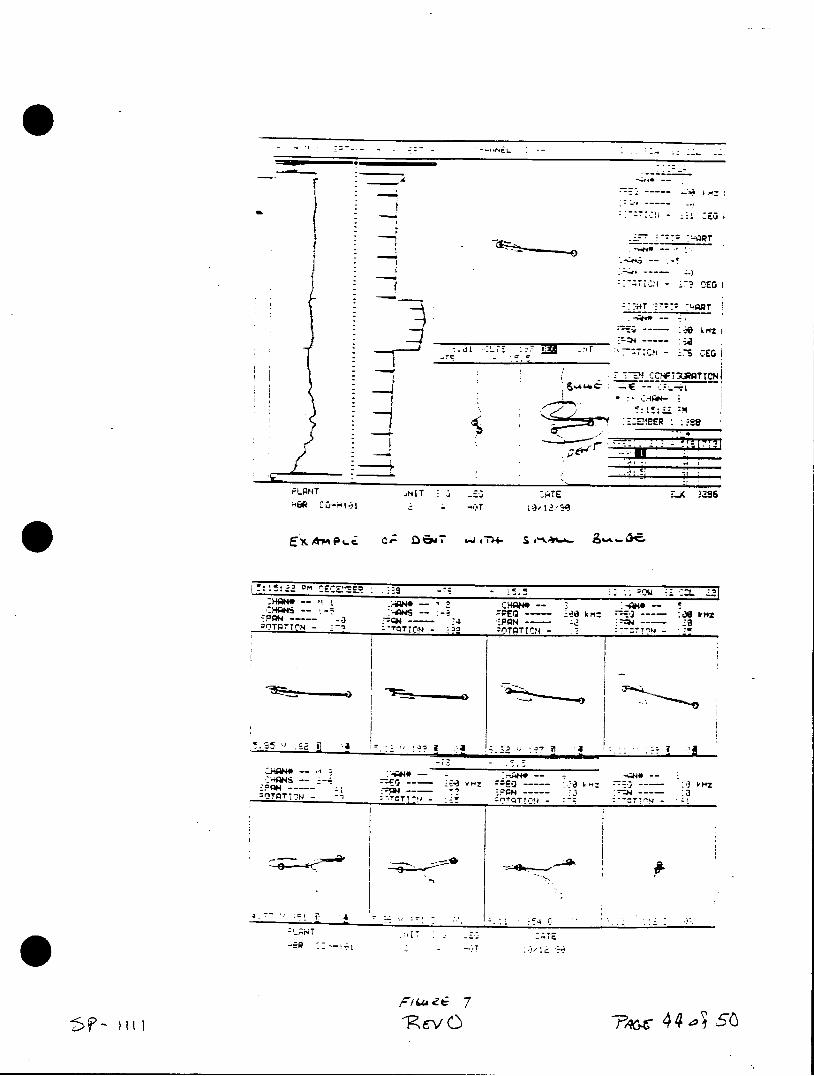
- --- - -
-:-I E-G
- 3CEr
q -"
in - DE
-*---
:---0 kHz I
.- 7 _77rr . -:7c - iS CEG
* -- :A
PLANT HNIT :A -TE .A 3386
P eN c4- 28 00ors
- -- S - --- REG -- ,km - --- :as trmZ -C#4 -- ' :PAN --- ---
iPT4 -OTON - TTION yyg
:PPH ----- N-
-TE
Lv 7 -Rev 0 44 .
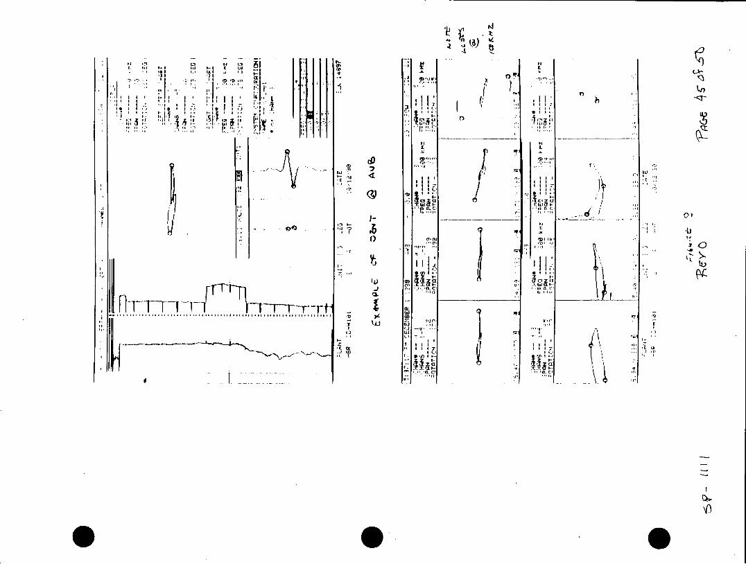
n 14
I cc II
to II'
IILI
Wja Ii -l
:I I& av
*1 , .-n Tf: z: z I
a. a a "a (I
rT-rT
....... ....... .......
I7 k.'.'
" ~ .i tl UP
-- ~~ "r e -\?
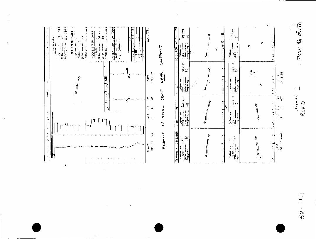
W4 I-, ul aNa Gor C. X.,*r
MI Id
III 11 1
on, CM a 3i. ~z C.450 it,
. ~ ~ ~ .1 II "C" .
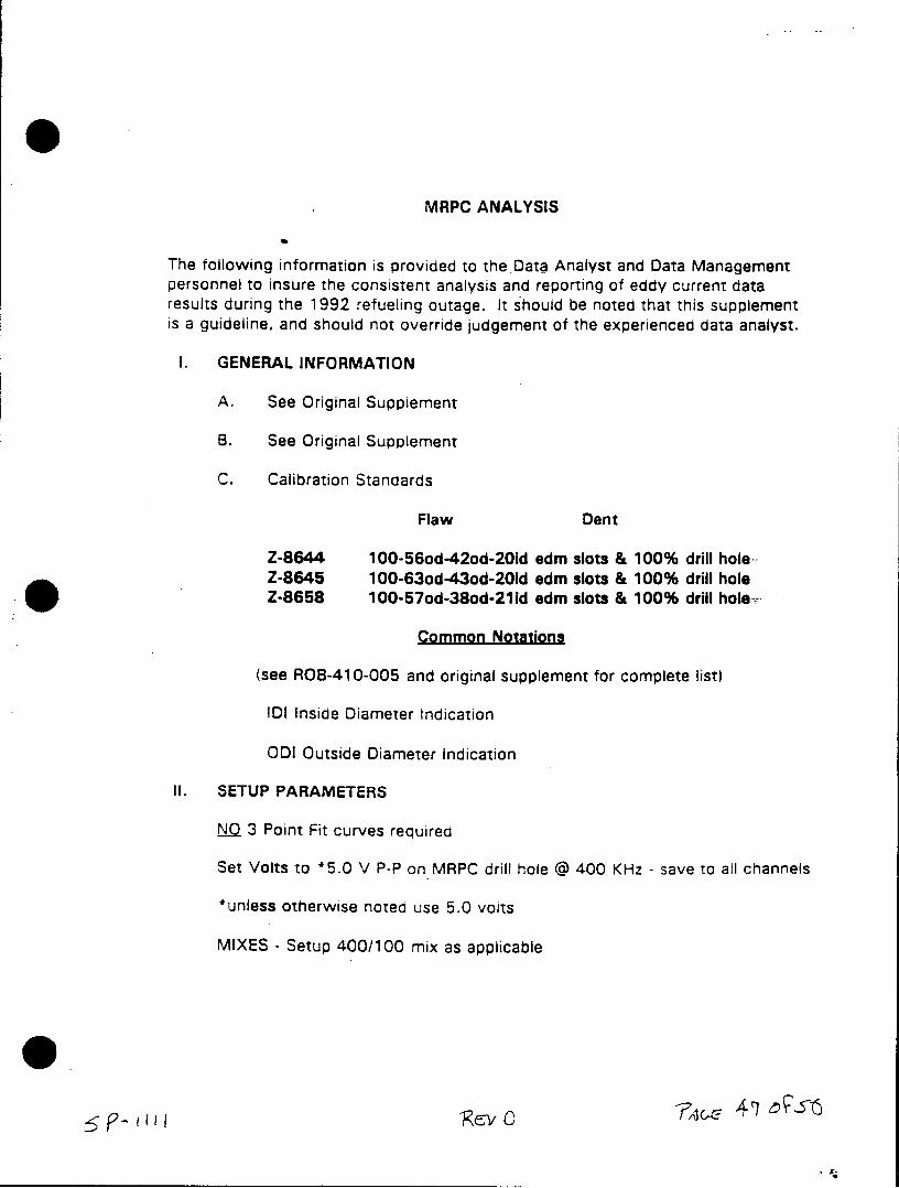
S MRPC ANALYSIS
The following information is provided to the-Data Analyst and Data Management personnel to insure the consistent analysis and reporting of eddy current data results during the 1992 refueling outage. It should be noted that this supplement is a guideline, and should not override judgement of the experienced data analyst.
I. GENERAL INFORMATION
A. See Original Supplement
B. See Original Supplement
C. Calibration Standards
Flaw Dent
Z-8644 100-56od-42od-20id edm slots & 100% drill hole Z-8645 100-63od-43od-20id edn slots & 100% drill hole Z-8658 100-57od-38od-211d edn slots & 100% drill hole,
Common Notations
(see ROB-410-005 and original supplement for complete list)
IDI Inside Diameter Indication
ODI Outside Diameter Indication
II. SETUP PARAMETERS
NQ 3 Point Fit curves required
Set Volts to *5.0 V P-P on MRPC drill hole @ 400 KHz - save to all channels
*unless otherwise noted use 5.0 volts
MIXES - Setup 400/100 mix as applicable
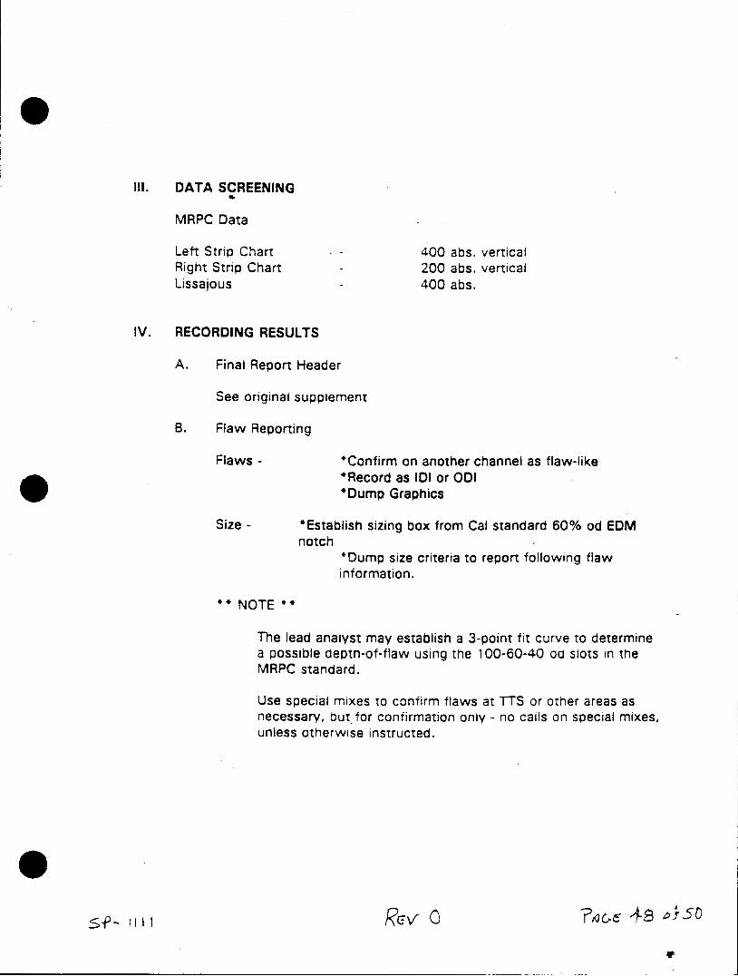
III. DATA SCREENING
MRPC Data
Left Strip Chart - 400 abs. vertical Right Strip Chart - 200 abs. vertical Lissajous 400 abs.
IV. RECORDING RESULTS
A. Final Report Header
See original supplement
B. Flaw Reporting
Flaws - *Confirm on another channel as flaw-like *Record as IDI or ODI *Dump Graphics
Size - *Establish sizing box from Cal standard 60% od EDM notch
*Dump size criteria to report following flaw information.
NOTE **
The lead analyst may establish a 3-point fit curve to determine a possible depth-of-flaw using the 100-60-40 od slots in the MRPC standard.
Use special mixes to confirm flaws at TTS or other areas as necessary, but for confirmation only - no calls on special mixes, unless otherwise instructed.
gtV
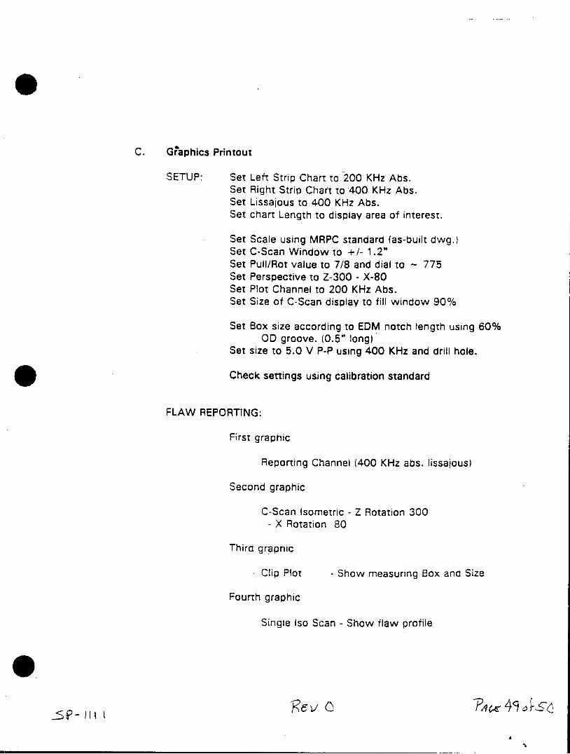
C. Graphics Printout
SETUP: Set Left Strip Chart to 200 KHz Abs. Set Right Strip Chart to 400 KHz Abs. Set Lissajous to 400 KHz Abs. Set chart Length to display area of interest.
Set Scale using MRPC standard (as-built dwg.) Set C-Scan Window to +/- 1.2" Set Pull/Rot value to 7/8 and dial to - 775 Set Perspective to Z-300 - X-80 Set Plot Channel to 200 KHz Abs. Set Size of C-Scan display to fill window 90%
Set Box size according to EDM notch length using 60% OD groove. (0.5" long)
Set size to 5.0 V P-P using 400 KHz and drill hole.
Check settings using calibration standard
FLAW REPORTING:
First graphic
Reporting Channel (400 KHz abs. lissajous)
Second graphic
C-Scan Isometric - Z Rotation 300 - X Rotation 80
Third graphic
Clip Plot - Show measuring Box and Size
Fourth graphic
Single Iso Scan - Show flaw profile
?4*
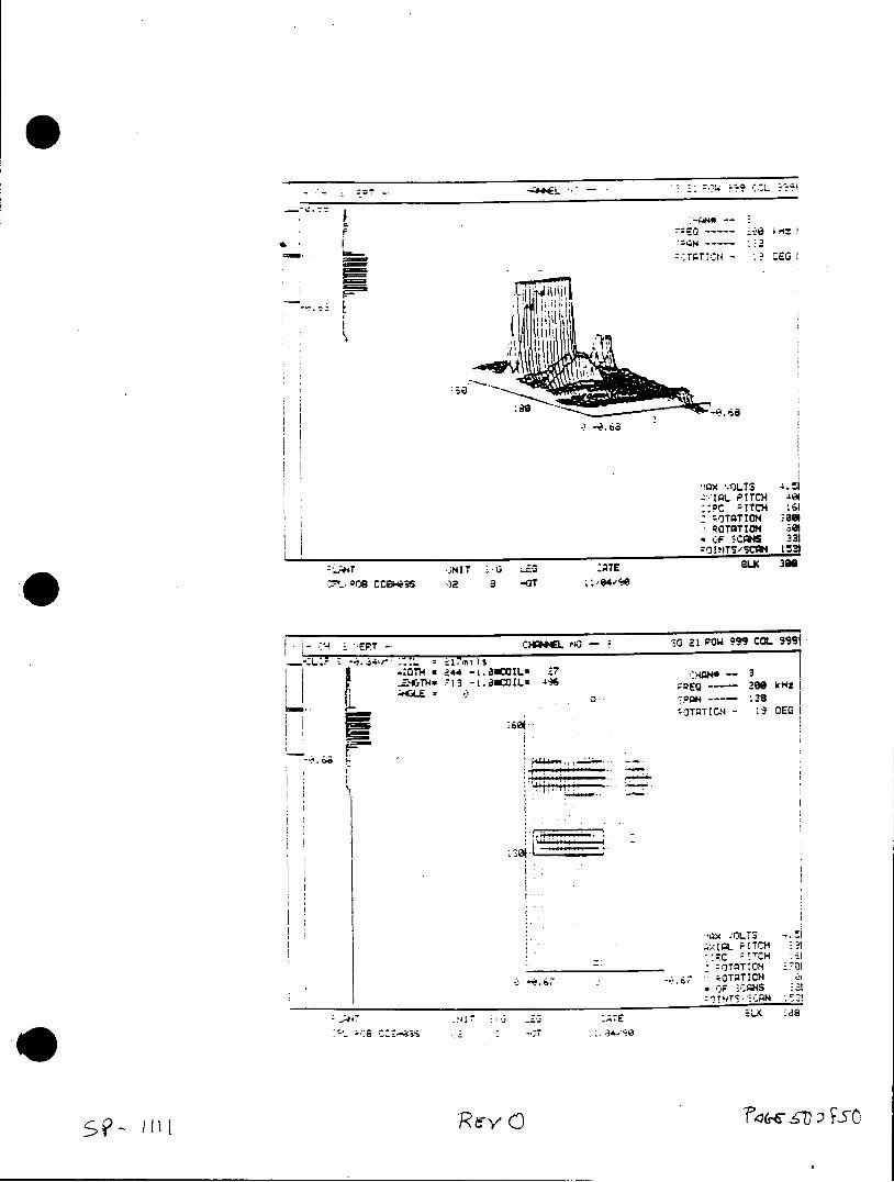
SZ --TTN CE
F1jil
i'Qx vrJLTS 4. t Z:-IAL PITCH 401
* ::PC ;!TC 161 Z-OTATtOH -80 ROTATION BM
.F 3cpm 331 !HOITS"cm4 t531
*JNT G iO:PTE &AG 306
OT 244 -i.a6CO!L- £7 _zTH*713-i04CIL2413 EQ -- 200 IcMZ
:PQ-- 138 OTATION - 3 EG I
*'QX VOLTS IpL PITCH _,I
* -- Tc TO*Cx 0I
j ".67 J CF ,CAHS 1 :M14 'r -Z -, 2
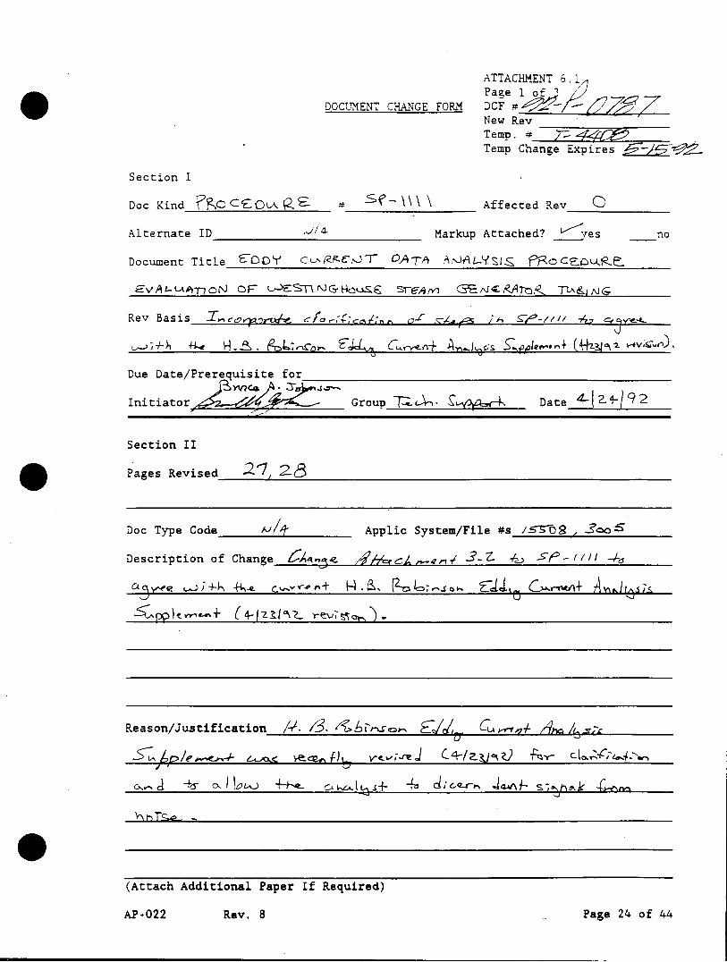
ATTACHMENT 6.1
DOCUMENT CHANGE FORM DF 1 _ _ _
New Rev Temp. # Temp Change Expires /
Section I
Doc Kind aC CEOLA P Affected Rev O
Alternate ID Markup Attached? les no
Document Title O CuRACNJT DATA APAL-YSIZ MacujowR
EVAt- ARnorN OFr LSNaGHOuZS Srg-4(y C TA&ING
Rev Basis I-ce,, -tWe c 0-( /A f-/1// 74 vt 4
Due Date/Prerequisite for
Initiator Group -T7A- £Date 4.9- 92
Section II
Pages Revised 2 ,1 28
Doc Type Code /-1 Applic System/File #s /STS , 2cloS
Description of Change 4e r 3.7 .; . /I/1 4 -2
Reason/Justification /. S. Abibre C 4 Ay s
c,, 4<s IaL-.) ±+.. c 2 t 4o r~
(Attach Additional Paper If Required)
AP-022 Rev. 8 Page 24 of 44
ATTACHMENT 6.1 ?age 2 Of 3
DOCUMENT CHANGE FORM DCF
Section II (cont.) ~7 7
Affected Documents Kind Number Title
__ I I___________________
Comments
Document Released For Review
Preparerac 4 Z4 < i Group 72c. ate-* Date________
Recommender Title Date
Recommended Effective Date
Training required before becoming effective? yes no
description
AP-022 Rev. 8 Page 25 of 44
ATTACHMENT 6.L Page 3 o 3 ^
DOCUMENT CHANGE FORM DCF Section III STo Not Assigned Reviewer's
Type of Review Req'd Req'd Reviewer Signa/Date (See ATTACH 6.3) (per ATTACHMENT 6.4)
1. Design Verification I___ ______|See Design Verification Package
2. Technical _1 __ |_ |
3. Nuclear Safety ]_ _____See Safety Review Package
4. 1OCFR50 App. R | | |
5a. Environmental Qual. | _ _ 1
5b. R.G. 1.97 | _ |
6. PNSC | _
7. NAD |__ _ __ __ _____Review done, Ref.
I _ Review may follow approval
8. NRC |______|_ ___ Permission to proceed, Ref.
(per Reg. Comp., signa/date 9. In-Service Inspec. I I _ _II
10. System/Compon. Engrgl
11a.Operations |
llb.Human Factors |
12. Simulator |
13. Maint-Elec/I&C |
14. Maint-Mech/Insul |
15. Installation
16. E&RC
17. ALARA 18. Security
19. Fire Protection
20. Quality Ver. Section I
21. Checker
22. Project Coordinator
23. Other
24. Other
25. Other
Temporary Change Approval A temporary change has a maximum duration of 21 days.
"~ SRO__"- ________
Sgt~ire Management Title Date
Final Approval/ PNSC followup review Signature Date recommended
Void/Cancel Signature Date
Reason:
Section IV
Appropriate actions have been taken regarding these temporary changes to allow this Revision to become effective. (list)
Recommender Signa/Date
AP-022 Rev. 8 Page 26 of 44
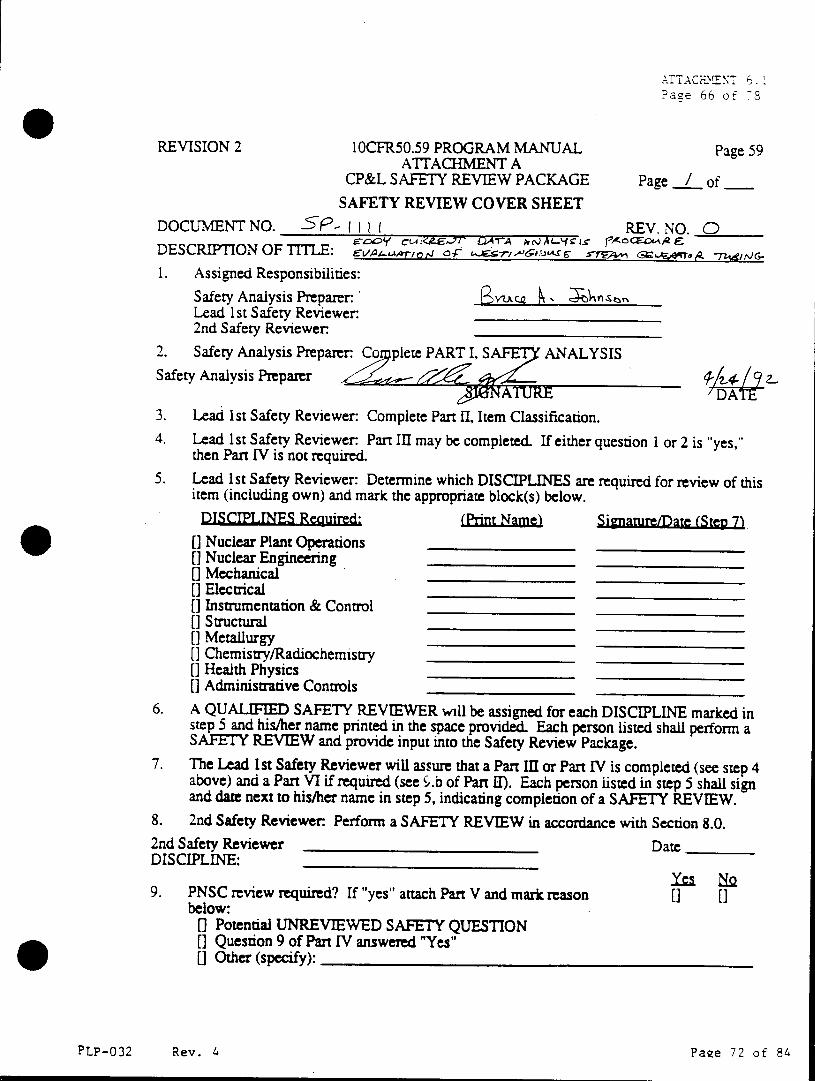
Page 66 of 78
REVISION 2 10CFR50.59 PROGRAM MANUAL Page 59 ATTACHMENT A
CP&L SAFETY REVIEW PACKAGE Page / of SAFETY REVIEW COVER SHEET
DOCUMENT NO. SP- I I REV. NO. 0 DESCRIPTION OF TITLE: evAuse i 4 or ea0n rL <sEo ,g;
1. Assigned Responsibilities:
Safety Analysis Preparer: 4%vauce Lead 1st Safety Reviewer:
2nd Safety Reviewer.
2. Safety Analysis Preparer: Co plete PART I, S ANALYSIS Safety Analysis Preparer 4.
JNAT Ukh DATE 3. Lead 1st Safety Reviewer: Complete Part II, Item Classification. 4. Lead 1st Safety Reviewer: Part III may be completed. If either question I or 2 is "yes,"
then Part IV is not required.
5. Lead 1st Safety Reviewer: Determine which DISCIPLINES are required for review of this item (including own) and mark the appropriate block(s) below.
DISCIPLINES Required: (PrnLae Signature/Date (Step 7 []Nuclear Plant Operations [] Nuclear Engineering []Mechanical [ Electrical
[]Instrumentation & Control
[I Structural
[]Metallurgy []Chemistry/Radiochemistry []Health Physics
[ Administrative Controls
6. A QUALIFIED SAFETY REVIEWER will be assigned for each DISCIPLINE marked in step 5 and his/her name printed in the space provided. Each person listed shall perform a SAFETY REVIEW and provide input into the Safety Review Package.
7. The Lead 1st Safety Reviewer will assure that a Part III or Part IV is completed (see step 4 above) and a Part VI if required (see '.b of Part II). Each person listed in step 5 shall sign and date next to his/her name in step 5, indicating completion of a SAFETY REVIEW.
8. 2nd Safety Reviewer Perform a SAFETY REVIEW in accordance with Section 8.0. 2nd Safety Reviewer Date DISCIPLINE:
9. PNSC review required? If "yes" attach Part V and mark reason [] [] below:
0 Potential UNREVIEWED SAFETY QUESTION [a Question 9 of Part IV answered "Yes" 0 Other (specify):
PLP-032 Rev. 4 Paee 72 of 84
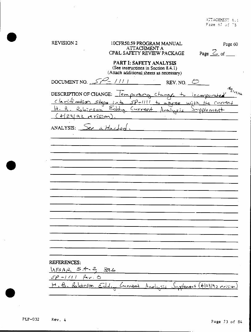
Page 67 o: .S
REVISION 2 10CFR50.59 PROGRAM MANUAL Page 60 ATTACHMENT A
CP&L SAFETY REVIEW PACKAGE Page of___
PART I: SAFETY ANALYSIS (See instructions in Section 8.4.1)
(Attach additional sheets as necessary)
DOCUMENT NO. i - / /1) REV. NO. _
DESCRIPTION OF CHANGE: =p12ra c Cuvj, I, em e ras
ANALYSIS: t J
REFERENCES:
PLP-032 Rev. 4 Page 73 of 84
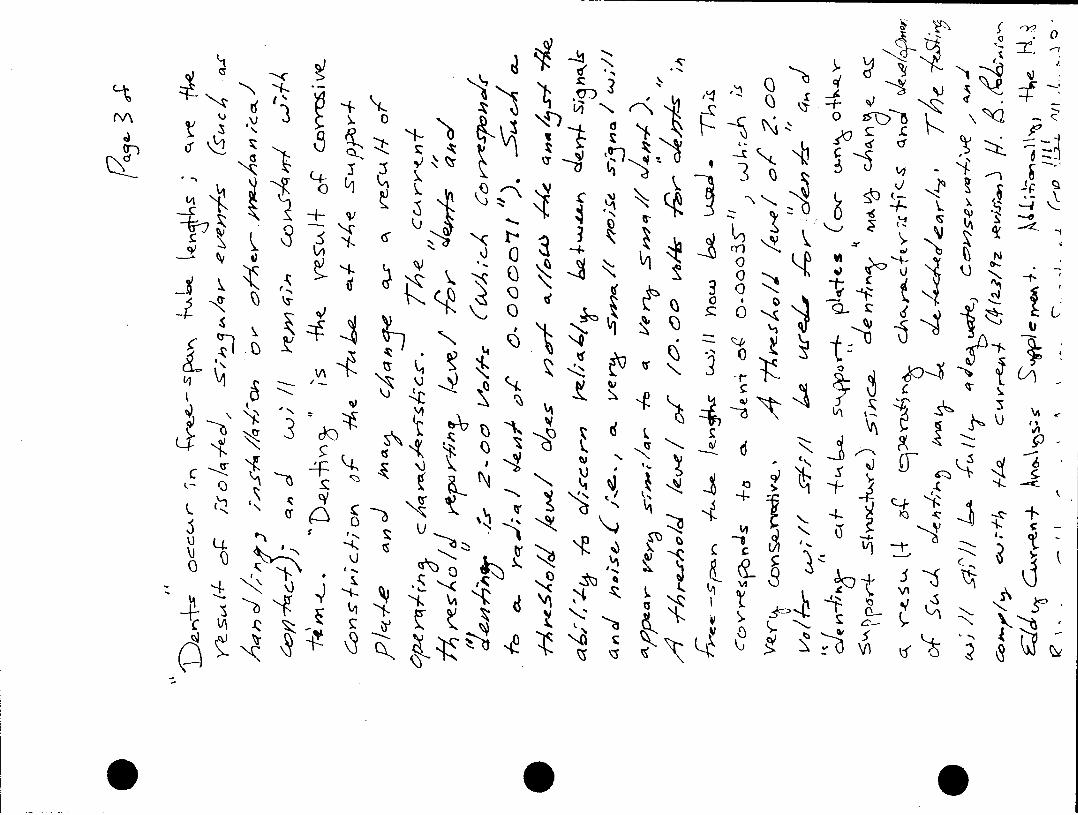
'NNZ
kr~
b)7K"
kjt Ll
3Q C L9
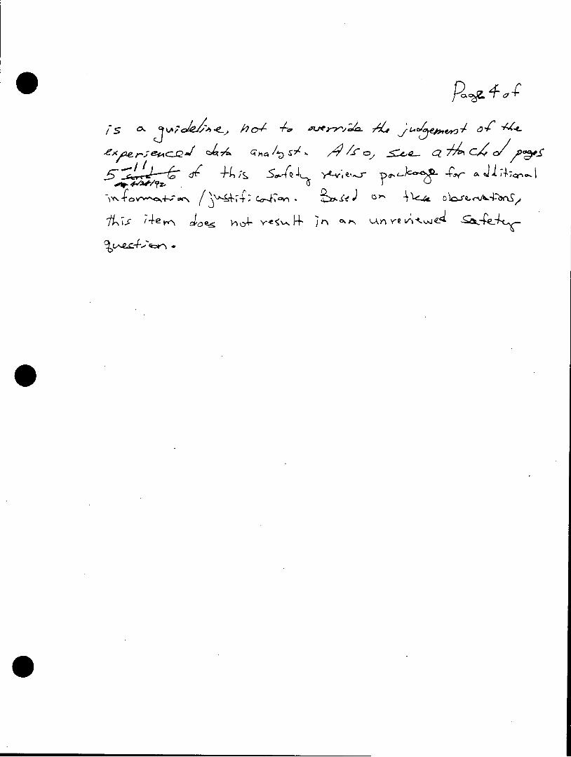
*, /s . ho, 0 +, dLorvae{Q- & .,
AL"v - f'~ agesq c7 aosA ,/ ,a4 c,4,/ 077;)
5 ve 40 sAJ yye e0 v:Je
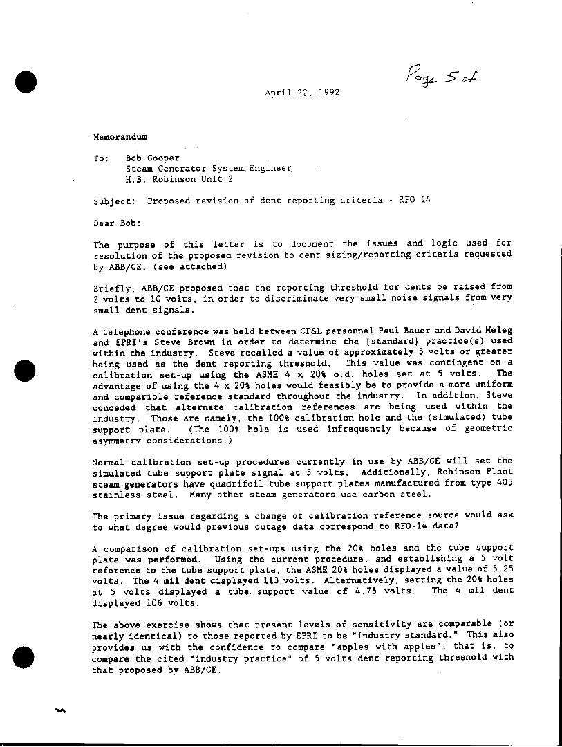
April 22, 1992
Memorandum
To: Bob Cooper Steam Generator SystemEngineer H.B. Robinson Unit 2
Subject: Proposed revision of dent reporting criteria - RFO 14
Dear Bob:
The purpose of this letter is to document the issues and logic used for
resolution of the proposed revision to dent sizing/reporting criteria requested
by ABB/CE. (see attached)
Briefly, ABB/CE proposed that the reporting threshold for dents be raised from
2 volts to 10 volts, in order to discriminate very small noise signals from very small dent signals.
A telephone conference was held between CP&L personnel Paul Bauer and David Meleg and EPRI's Steve Brown in order to determine the (standard) practice(s) used
within the industry. Steve recalled a value of approximately 5 volts or greater
being used as the dent reporting threshold. This value was contingent on a
calibration set-up using the ASME 4 x 20% o.d. holes set at 5 volts. The
advantage of using the 4 x 20% holes would feasibly be to provide a more uniform and comparible reference standard throughout the industry. In addition, Steve
conceded that alternate calibration references are being used within the
industry. Those are namely, the 100% calibration hole and the (simulated) tube support plate. (The 100% hole is used infrequently because of geometric asymmetry considerations.)
Normal calibration set-up procedures currently in use by ABB/CE will set the simulated tube support plate signal at 5 volts. Additionally, Robinson Plant
steam generators have quadrifoil tube support plates manufactured from type 405
stainless steel. Many other steam generators use carbon steel.
The primary issue regarding a change of calibration reference source would ask
to what degree would previous outage data correspond to RFO-14 data?
A comparison of calibration set-ups using the 20% holes and the tube support plate was performed. Using the current procedure, and establishing a 5 volt reference to the tube support plate, the ASME 20% holes displayed a value of 5.25 volts. The 4 mil dent displayed 113 volts. Alternatively, setting the 20% holes
at 5 volts displayed a tube support value of 4.75 volts. The 4 mil dent displayed 106 volts.
The above exercise shows that present levels of sensitivity are comparable (or
nearly identical) to those reported by EPRI to be "industry standard." This also
provides us with the confidence to compare "apples with apples"; that is, to
compare the cited "industry practice" of 5 volts dent reporting threshold with
that proposed by ABB/CE.
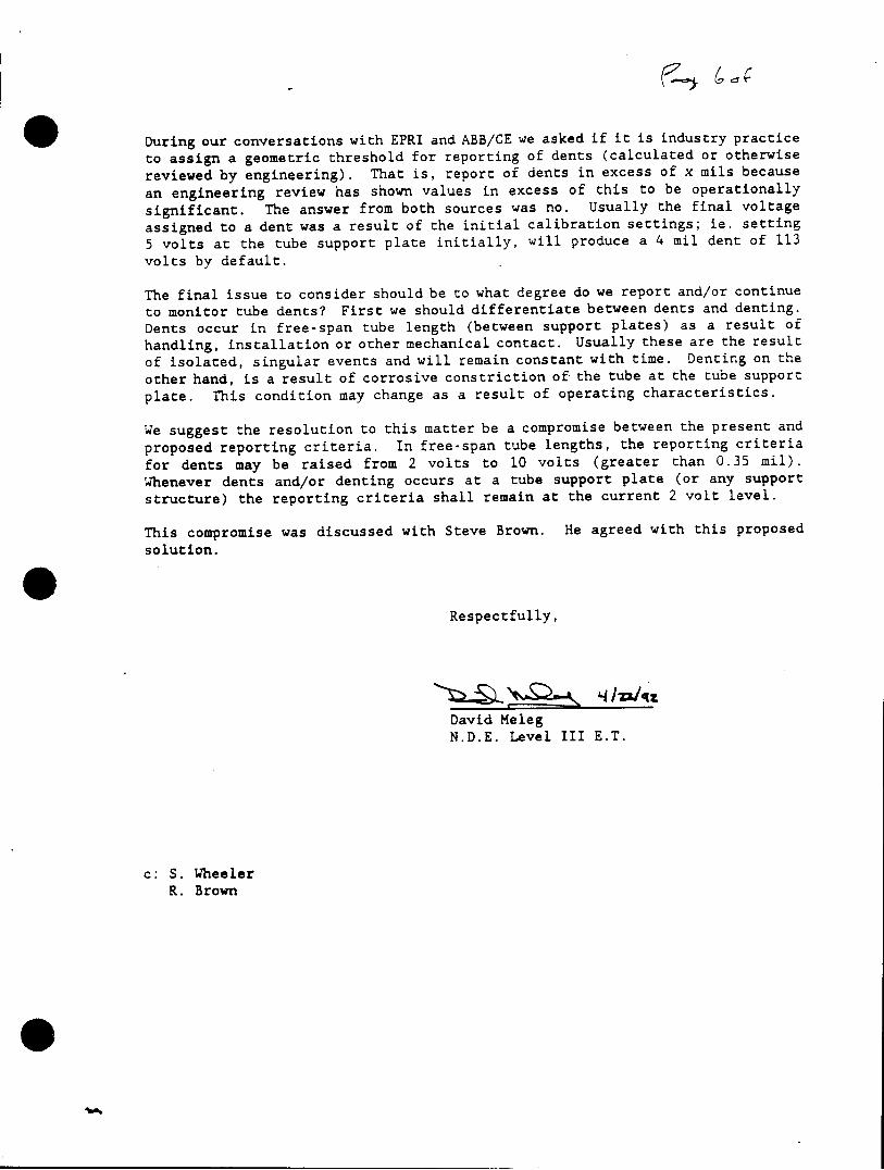
During our conversations with EPRI and ABB/CE we asked if it is industry practice to assign a geometric threshold for reporting of dents (calculated or otherwise
reviewed by engineering). That is, report of dents in excess of x mils because
an engineering review has shown values in excess of this to be operationally
significant. The answer from both sources was no. Usually the final voltage
assigned to a dent was a result of the initial calibration settings; ie. setting 5 volts at the tube support plate initially, will produce a 4 mil dent of 113
volts by default.
The final issue to consider should be to what degree do we report and/or continue
to monitor tube dents? First we should differentiate between dents and denting. Dents occur in free-span tube length (between support plates) as a result of
handling, installation or other mechanical contact. Usually these are the result
of isolated, singular events and will remain constant with time. Denting on the
other hand, is a result of corrosive constriction of the tube at the tube support
plate. This condition may change as a result of operating characteristics.
We suggest the resolution to this matter be a compromise between the present and
proposed reporting criteria. In free-span tube lengths, the reporting criteria
for dents may be raised from 2 volts to 10 volts (greater than 0.35 mil). Whenever dents and/or denting occurs at a tube support plate (or any support structure) the reporting criteria shall remain at the current 2 volt level.
This compromise was discussed with Steve Brown. He agreed with this proposed
solution.
Respectfully,
q4 721
David Meleg N.D.E. Level III E.T.
c: S. Wheeler R. Brown
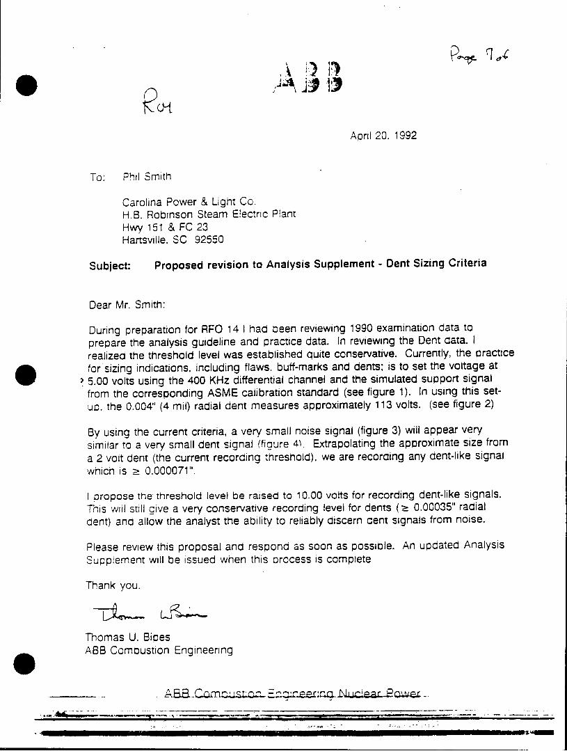
April 20. 1992
To: Phil Smith
Carolina Power & Light Co. H.B. Robinson Steam Electric Plant Hwy 151 & FC 23 Hartsville. SC 92550
Subject: Proposed revision to Analysis Supplement - Dent Sizing Criteria
Dear Mr. Smith:
During preparation for RFO 14 I had been reviewing 1990 examination data to prepare the analysis guideline and practice data. In reviewing the Dent data. I realized the threshold level was established quite conservative. Currently, the practice for sizing indications, including flaws. buff-marks and dents; is to set the voltage at 5.00 volts using the 400 KHz differential channel and the simulated support signal from the corresponding ASME calibration standard (see figure 1). In using this setup. the 0.004" (4 mil) radial dent measures approximately 113 volts. (see figure 2)
By using the current criteria, a very small noise signal (figure 3) will appear very similar to a very small dent signal (figure 4). Extrapolating the approximate size from a 2 volt dent (the current recording threshold), we are recording any dent-like signal which is - 0.000071".
I propose the threshold level be raised to 10.00 volts for recording dent-like signals. This will still give a very conservative recording level for dents (2 0.00035" radial dent) and allow the analyst the ability to reliably discern dent signals from noise.
Please review this proposal and respond as soon as possible. An updated Analysis Supplement will be issued when this process is complete
Thank you.
Thomas U. Bipes ABB Comoustion Engineering
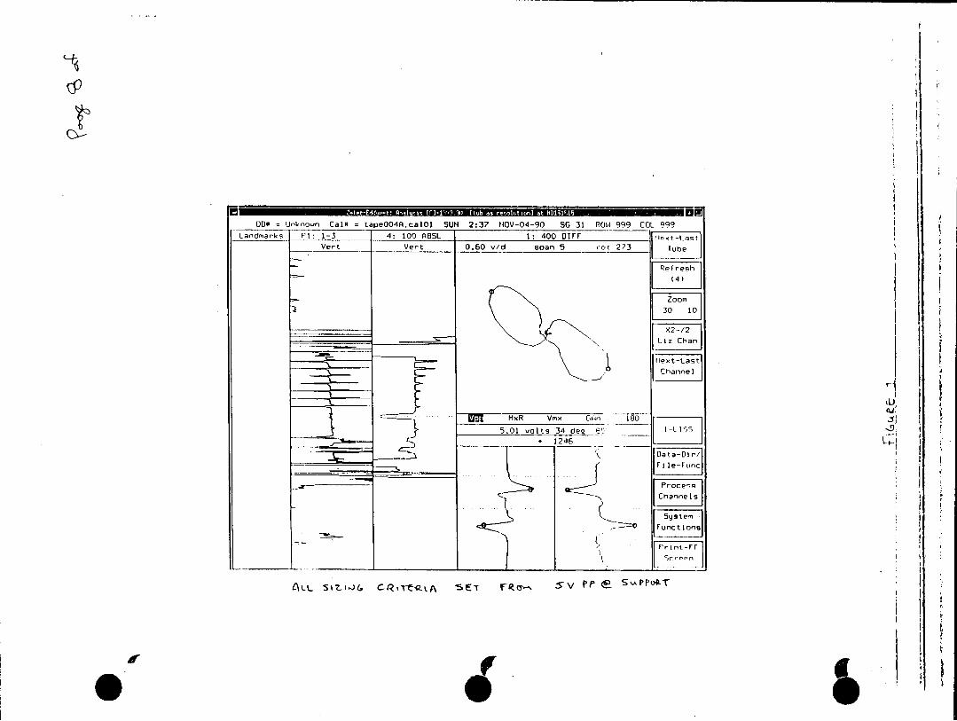
DO Urknovn Cal# tape0O4A.calol SUN 2:37 NOV-04-90 SG 31 ROW 999 COL 999a
VetVert 0.60 v/d span 5 r:t273 Tube
ext-Last
Channel
. .... MxR Vmx GCA 180 d 5.01 volts 34 deq 1 ____f
*1246 ___[
_ leunc
[15Y'
AL S17-106 C-RTQ-kA SIET IFI 3- Sv S'F %APP~
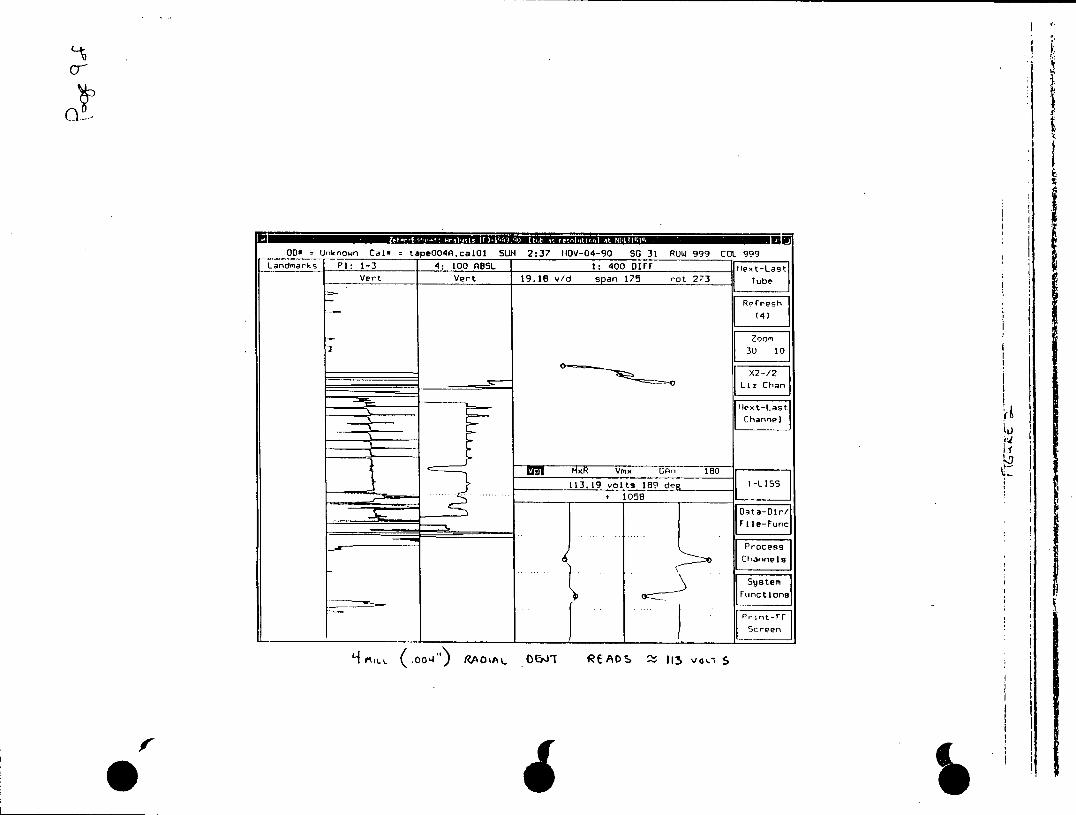
CT
OD= Unknown Cal tapeO4A.calO1 SUN 2:37 IIOV-04-90 SG 31 ROW 999 COL 999 Landmarks P1: 1-3 4: 100 ABSL 1: 400 DIFF Ie7t-La.T
Vert Vert 19.18 v/d span 175 rot 273 Tube
Refresh
(4)
2X2-/2 Liz Chan
Channel
Ehl MxR vmx GAn 180
113.19 volts 189 deg 1LS .. . ... ... . . ... ... + 1O S 8
Doata-Dir/j --- File-Fune
Channels
System Functione
Print-FF
elLh ,oo14 RAoa A 0 OlT READS 1Z-, von 5
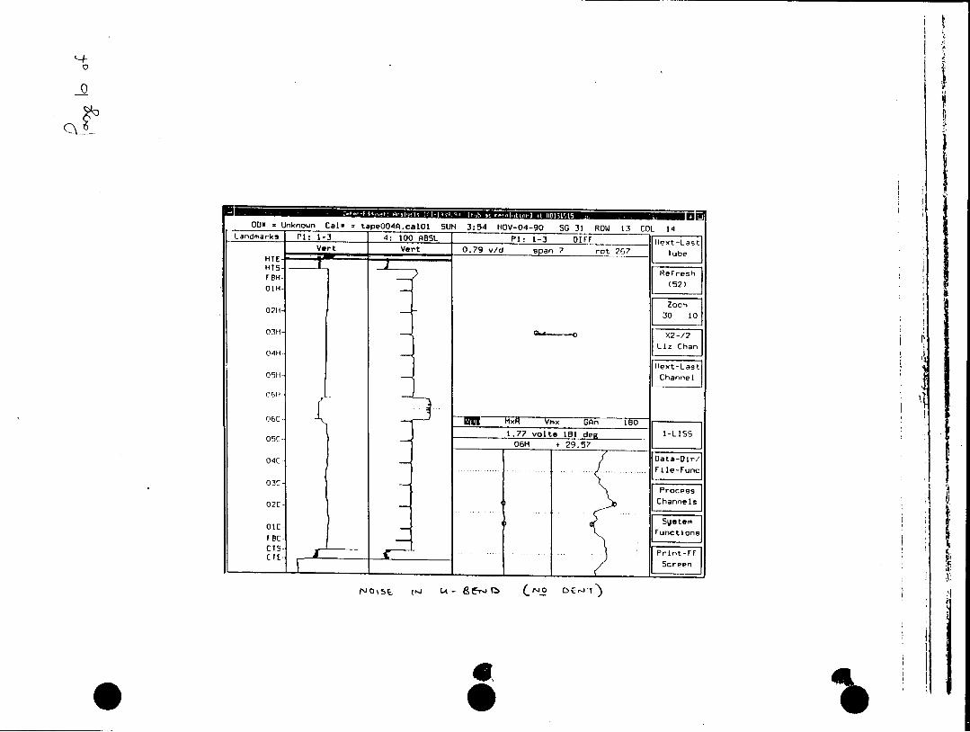
OUP = Unknown Calm tapeOO4A.calOl SUN 3:54 NOV-04-90 SG 31 ROWJ 13 COL 14 Landmarks PI: 1-3 4: 100 ABSL P1: 1-3 01FF [ Lst
Vert Vert 0.79 v/d span 7 rot 267 !Iubel NITE
TEN- (52) OIN
I
02H
0- I0 X22 05HLi Chan
04H
06C - EI MxR Vmx GAr, 180 1.7? volts 181 te 05C- 06H + 29.5?711 1 .... ..... ... ..... .. ... . ... I F l -u n c l
O 3C Pocs
02C- Channels
FEC- 1unctions1
C.... FPrin- t-Fr-T Scree
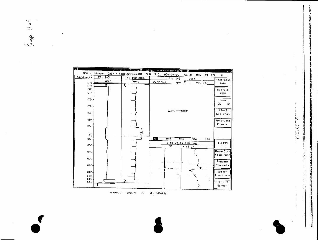
003 Unknown Cal*f tapeOO4A.calOI SUN 3:01 NOV-04-90 SG 31 ROW 23 COL La-dlarks P1: 1-3 4: 100 ASSL P1: 1-3 D1FF Ls
VerTEer 0.79 v/d span 7 rot 267 !TubeI
02H-Zo
03H
LizChn
05H- N xF-Las
06H Cane
03C
03C
C5 Ct 7 prnt-Fr
~ ~ ~ L~eScreen
'S^ E. T - 6A -
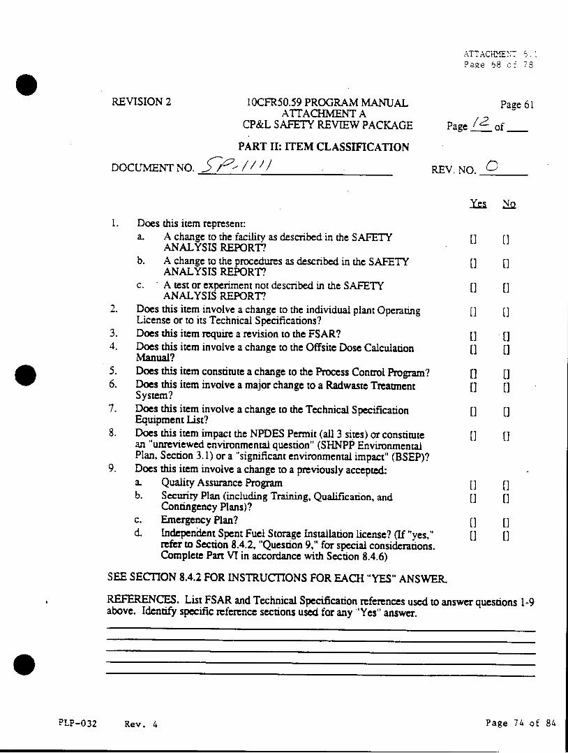
ATTAC'c!ENT 6.1 Page 68 of 78
REVISION 2 10CFR50.59 PROGRAM MANUAL Page 61 ATTACHMENT A
CP&L SAFETY REVIEW PACKAGE Page of
PART II: ITEM CLASSIFICATION
DOCUMENT NO. / / REV. NO.
1. Does this item represent: a. A change to the facility as described in the SAFETY [] []
ANALYSIS REPORT? b. A change to the procedures as described in the SAFETY [] []
ANALYSIS REPORT? c. A test or experiment not described in the SAFETY [] [0
ANALYSIS REPORT? 2. Does this item involve a change to the individual plant Operating [I []
License or to its Technical Specifications? 3. Does this item require a revision to the FSAR? [] [1 4. Does this item involve a change to the Offsite Dose Calculation [] []
Manual? 5. Does this item constitute a change to the Process Control Program? [] (0 6. Does this item involve a major change to a Radwaste Treatment [] []
System? 7. Does this item involve a change to the Technical Specification [] []
Equipment List? 8. Does this item impact the NPDES Permit (all 3 sites) or constitute [] []
an "unreviewed environmental question" (SHNPP Environmental Plan, Section 3.1) or a "significant environmental impact" (BSEP)?
9. Does this item involve a change to a previously acceptedk a. Quality Assurance Program [] [] b. Security Plan (including Training, Qualification, and [] []
Contingency Plans)? c. Emergency Plan? [] [1 d. Independent Spent Fuel Storage Installation license? (If "yes," [] []
refer to Section 8.4.2, "Question 9," for special considerations. Complete Part VI in accordance with Section 8.4.6)
SEE SECTION 8.4.2 FOR INSTRUCTIONS FOR EACH "YES" ANSWER.
REFERENCES. List FSAR and Technical Specification references used to answer questions 1-9 above. Identify specific reference sections used for any "Yes" answer.
PLP-032 Rev. 4 Page 74 of 84
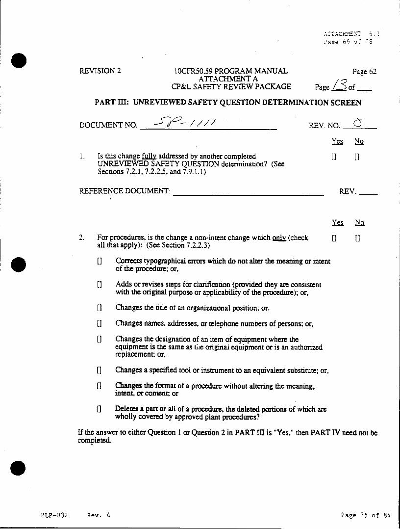
AAC E N7 6.2 Pace 69 of 78
REVISION 2 10CFR50.59 PROGRAM MANUAL Page 62 ATITACHMENT A
CP&L SAFETY REVIEW PACKAGE Page 3of
PART III: UNREVIEWED SAFETY QUESTION DETERMINATION SCREEN
DOCUMENT NO. -- / / REV. NO.
y-~
1. Is this change fuly addressed by another completed [] [] UNREVIEWED SAFETY QUESTION determination? (See Sections 7.2.1, 7.2.2.5, and 7.9.1.1)
REFERENCE DOCUMENT: REV.
2. For procedures, is the change a non-intent change which nLyX (check [] [] all that apply): (See Section 7.2.2.3)
([ Corrects typographical errors which do not alter the meaning or intent of the procedure; or,
[] Adds or revises steps for clarification (provided they are consistent with the original purpose or applicability of the procedure); or,
[] Changes the title of an organizational position; or,
[] Changes names, addresses, or telephone numbers of persons; or,
[] Changes the designation of an item of equipment where the equipment is the same as the original equipment or is an authorized replacement; or,
[] Changes a specified tool or instrument to an equivalent substitute; or,
[] Changes the format of a procedure without altering the meaning, intent, or content; or
0 Deletes a part or all of a procedure, the deleted portions of which are wholly covered by approved plant procedures?
If the answer to either Question I or Question 2 in PART III is "Yes," then PART IV need not be completed.
PLP-032 Rev. 4 Page 75 of 84
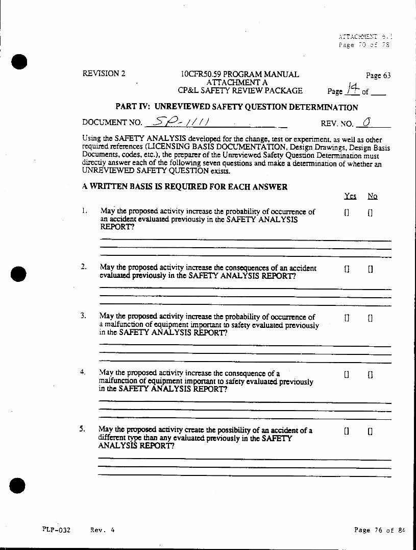
Page 70 of7
REVISION 2 10CFR50.59 PROGRAM MANUAL Page 63 ATrACHMENT A
CP&L SAFETY REVIEW PACKAGE Page of
PART IV: UNREVIEWED SAFETY QUESTION DETERMINATION
DOCUMENT NO. iSP- // /1 REV. NO. J Using the SAFETY ANALYSIS developed for the change, test or experiment, as well as other required references (LICENSING BASIS DOCUMENTATION, Design Drawings, Design Basis Documents, codes, etc.), the preparer of the Unreviewed Safety Question Determination must directly answer each of the following seven questions and make a determination of whether an UNREVIEWED SAFETY QUESTION exists.
A WRITTEN BASIS IS REQUIRED FOR EACH ANSWER
1. May the proposed activity increase the probability of occurrence of [] [] an accident evaluated previously in the SAFETY ANALYSIS REPORT?
2. May the proposed activity increase the consequences of an accident [] [] evaluated previously in the SAFETY ANALYSIS REPORT?
3. May the proposed activity increase the probability of occurrence of [] [] a malfunction of equipment important to safety evaluated previously in the SAFETY ANALYSIS REPORT?
4. May the proposed activity increase the consequence of a [] [ malfunction of equipment important to safety evaluated previously in the SAFETY ANALYSIS REPORT?
5. May the proposed activity create the possibility of an accident of a [] [] different type than any evaluated previously in the SAFETY ANALYSIS REPORT?
PLP-032 Rev. 4 Page 76 of 8L
ATTACEXENT Pa2e 7Io51
REVISION 2 10CFR50.59 PROGRAM MANUAL Page 64 ATTACHMENT A
CP&L SAFETY REVIEW PACKAGE Page i.of PART IV: (Continued)
6. May the proposed activity create the possibility of a malfunction of [3 [] equipment important to safety of a different type than any evaluated previously in the SAFETY ANALYSIS REPORT?
7. Does the proposed activity reduce the margin of safety as defined in [] [] the basis of any Technical Specification?
8. Based on the answers to questions 1 - 7, does this item result in an [] [] UNREVIEWED SAFETY QUESTION? If the answer to any of the questions 1-7 is "Yes", then the item is considered to constitute an UNREVIEWED SAFETY QUESTION.
9. Is PNSC review required for any of the following reasons? [] [3
If, in answering question 1 or 3 "No," it was determined that the probability increase was small relative to the uncertainties; or, in answering question 2 or 4 "No," it was determined that the doses increased, but the dose was still less than the NRC ACCEPTANCE LIMIT; or, in answering question 7 "No," a parameter would be closer to the NRC ACCEPTANCE LIMIT, but the end result was still within the NRC ACCEPTANCE LIMIT; then PNSC review is required.
REFERENCES:
This Unreviewed Safety Question Determination is for the following DISCIPLINE(s): (Additional Part IV forms may be included as appropriate.)
U Nuclear Plant Operations 0 Structural 0 Nuclear Engineering 0 Metallurgy [] Mechanical 0 Chemistry/Radiochemistry *Electical U Health Physics ]Instrumentation & Control [ Administrative Controls
PLP-032 Rev. 4 Page 77 of 84
ATTACHMENT 6.1
Page '2 of 78
REVISION 2 10CFR50.59 PROGRAM MANUAL Page 65 ATTACHMENT A
CP&L SAFETY REVIEW PACKAGE Page of
PART V: PNSC REVIEW
DOCUMENT NO. 2 - / / REV. NO. (
Determination/Evaluation:
Action Taken:
Basis:
PNSC Chairman: Date:
PLP-032 Rev. 4 Page 78 of 84
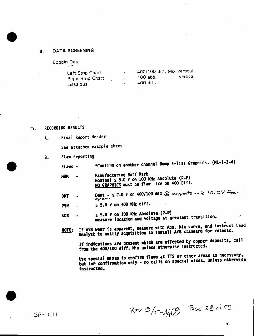
III. DATA SCREENING
Bobbin Data
Left Strip Chart - 400/100 diff. Mix vertical
Right Strip Chart - 100 abs. vertical
Lissajous 400 diff.
IV. RECORDING RESULTS
A. Final Report Header
See attached example sheet
B. Flaw Reporting
Flaws - *Confirm on another channel Dp 4-liss Graphics. (1-1-3-4)
MOM - Manufacturing Buff Mark Nominal z 5.0 V on 100 KHZ Absolute (P-P) NO GRAPHICS mst be flaw like on 400 01ff.
DNT - Dent z 2.0 V on 400/100 Mix & 0
PVN - z 5.0 V on 400 KIz diff.
ADR - z 5.0 V on 100 KHz Absolute (P-P) measure location and voltage at greatest transition.
NTE: If AVS wear is apparent, measure with Abs. Mix curve, and instruct Lead
- Analyst to notify acquisition to Install AVB standard for retests.
If indications are present which are affected by copper deposits, call
from the 400/100 diff. Mix unless otherwise instructed.
Use special mixes to confirm flaws at TTS or other areas as necessary, but for confirmation only - no calls on special mixes, unless otherwise instructed.
4111
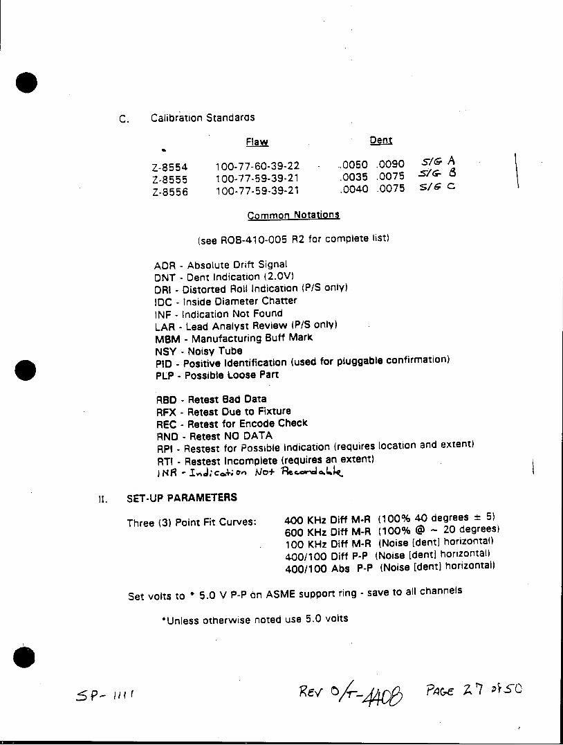
C. Calibration Standards
Flaw Dent
Z-8554 100-77-60-39-22 - -.0050 .0090 si/ A
Z-8555 100-77-59-39-21 .0035 .0075 vc 8
Z-8556 100-77-59-39-21 .0040 .0075 S/ C
Common Notations
(see ROB-410-005 R2 for complete list)
ADR - Absolute Drift Signal DNT - Dent Indication (2.OV) DRI - Distorted Roll indication (P/S only) IDC - Inside Diameter Chatter INF - Indication Not Found LAR - Lead Analyst Review (P/S only) MBM - Manufacturing Buff Mark NSY - Noisy Tube PID - Positive Identification (used for pluggable confirmation) PLP - Possible Loose Part
RBD - Retest Bad Data RFX - Retest Due to Fixture REC - Retest for Encode Check RND - Retest NO DATA RPI - Restest for Possible indication (requires location and extent)
RTI - Restest Incomplete (requires an extent)
II. SET-UP PARAMETERS
Three (3) Point Fit Curves: 400 KHz Diff M-R (100% 40 degrees ± 5) 600 KHz Diff M-R (100% @ - 20 degrees) 100 KHz Diff M-R (Noise (dent] horizontal) 400/100 Diff P-P (Noise (dent] horizontal) 400/100 Abs P-P (Noise (dent] horizontal)
Set volts to * 5.0 V P-P on ASME support ring - save to all channels
*Unless otherwise noted use 5.0 volts
I? f, 'Rev C 7_ V A-67
CAROLINA POWER AND LIGHT COMPANY H.B. ROBINSON SEG PLANT
SPECIAL PROCEDURE
SP-1112
CONTROL OF EDDY CURRENT EXAMINATION DATA USING THE PERSONAL COMPUTER (PC) DATA BASE SYSTEM
CONTROLLED g REVISION 0 RECIPIENT
Effective Date /_0
Expiration Date /Z
RECOMMENDED BY: __ _ _ _ _ _ _ _ _ _ _ 4-2- OL
Suxervisor Technical Support Date
APPROVED BY: ___
Manaer - Tec ical Support Daje
SP-1112 REV 0 PAGE 1 of 14
LIST OF EFFECTIVE PAGES
EFFECTIVE PAGES REVISION
Cover Sheet 0
LEP 0
3 through 14 0
SP-1112 REV 0 PAGE 2 of 14
TABLE OF CONTENTS
SECTION TITLE
1.0 Prerequisites
2.0 Precautions
3.0 Attachment
3.1 Control of Eddy Current Examination Data Using. the Personal Computer (PC) Data Base System
4.0 Disposition of Records
SP-1112 REV 0 PAGE 3 of 14
1.0 PREREQUISITES
Ensure individuals are on an appropriate RWP if work is to be performed inside the Radiation-Control Area.
This procedure has been reviewed per PLP-037 and it has been determined NOT to be applicable.
AI/J4 COi -717Unit / Section Manager Date
2.0 PRECAUTIONS
Use the principles of ALARA in planning and performing work and operations in the Radiation Control Area.
3.0 . ATTACHMENT
3.1 Control of Eddy Current Examination Data Using the Personal Computer (PC) Data Base System
4.0 DISPOSITION OF RECORDS
A copy of this procedure and the completed attachments shall be sent to the records vault for storage.
SP-1112 REV 0 PAGE 4 of 14
Paqe 1 of 10
CONTROL OF EDDY CURRENT EXAMINATION DATA
USING THE PERSONAL COMPUTER (PC) DATA BASE SYSTEM
PROCEDURE NO.
STD-410-076
REVISION 0
ABB COMBUSTION ENGINEERING NUCLEAR SERVICES
APPROVED BY: ___ DATE:
Level/III
APPROVED BY: 6y, ) -. DATE: Quality 0 W ations
APPROVED BY: DATE:
cog 9ant Supervisor
PROCEDURE: STD-410-076 REVISION: 0 PAGE: 2 of 10
TABLE OF CONTENTS
SECTION TITLE
1.0 OBJECTIVE
2.0 REFERENCES
3.0 PERSONNEL REQUIREMENTS
4.0 PRECAUTIONS AND PREREQUISITES
5.0 EDDY CURRENT DATA CONTROL
6.0 REPORTING CRITERIA
FIGURE 1 TYPICAL ACQUISITION/ANALYSIS TRACKING LOG (OM-5)
FIGURE 2 TYPICAL REEL/DDA-4 DATA DISK TRACKING LOG (DM-2)
FIGURE 3 TYPICAL ERROR RESOLUTION SHEET (DM-3)
FIGURE 4 TYPICAL PRIMARY/SECONDARY REPORT
PROCEDURE: STD-410-076 REVISION: 0 PAGE: 3 of 10.
1.0 OBJECTIVE
Control of Eddy Current Examination Data is the tracking, control. uploading, resolving and reporting of eddy current data whichhas been acquired during an eddy current examination. The eddy current data is tracked from arrival at the data management area until the final reports are presented to the client. To avoid data management discrepancies, specific forms, sign-offs, and procedures will be used
to ensure the efficient routing of the data cartridge tapes (DCR's), DDA-4 reports, and data management reports.
2.0 REFERENCES
2.1 Combustion Engineering Nuclear Power, Nuclear Quality Assurance Manual.
2.2 ISIS HX & SG Tube Data Management System Manual.
2.3 Applicable Analysis Guideline (if required).
2.4 Applicable Procedure for Eddy Current Inspection of Steam 2 Generators.
3.0 PERSONNEL REQUIREMENTS
Each person performing Data Management duties governed by this procedure shall be trained in the use and operation of the CE-ISIS data management system, and the specific requirements of this procedure.
3.1 The Data Controller shall be responsible for all editing performed on DDA-4 data files/disks or within the CE-ISIS data management system once the data has been transferred from the Analyst. The Data Controller may assign specific editing actions to an Analyst.
3.2 Data Management shall be responsible for tracking all eddy current data from the time it is delivered to the data management/analysis center until final reports of analysis results are submitted to the customer.
3.3 The ECT Level III Lead Analyst shall be responsible for the disposition of analysis discrepancies.
:Z;;Rev fl)Zr 7 a 14-
PROCEDURE: STD-410-076 REVISION: 0 PAGE: 4 of 10
4.0 PRECAUTIONS AND PREREQUISITES
4.1 The eddy current data management equipment will be set up in an area designated by the site personnel and approved by the vendor:
4.2 Eddy current data management checkoff sheets will be used to document tracking of the eddy current data throughout the data
management process.
4.3 Checkoff sheets may vary in form to meet specific requirements or modifications.
5.0 OPERATIONAL STEPS
The following will describe the data management sequence to be followed
to properly track the eddy current data and load the completed DDA-4
data files/disks to the data management system.
5.1 (Acquisition) Deliver the eddy current data package to the data
management center. The eddy- current data package shall consisV Of:
DCR tape (or as required) Operator examination sheets (or as required)
5.2 (Data Controller) Review the OCR tape labels to assure they are properly completed. Correct any discrepancie.s noted.
5.3 (Data Controller) Verify that the labels on the container and the tapes contain the same information.
5.4 (Data Controller) Log in the tapes on form DM-5 (Figure 1).
5.5 (System Administrator) Copy the DCR tape to an optical disk on
the Eddynet system and record on form DM-5 (Figure 1).
5.6 (Data Analysts) .Record on form OM-5 when files are being analyzed.
NOTE: THE FOLLOWING STEPS APPLY TO PRIMARY, SECONDARY, OR FINAL DATA
0DA-4.
5.7 (Data Analysts) If floppy disks are used, write protect the DDA-4 data disk when analysis is complete and return the DDA-4 hard
copy reports and ODA-4 data disks to the data management center.
Otherwise, return the DDA-4 hard copy reports to the data
management center. Record return of package on form DM-5.
5.8 (Data Controller) Review the DOA-4 hard copy report for correct
format and information.
SI- 1 1evo k i4
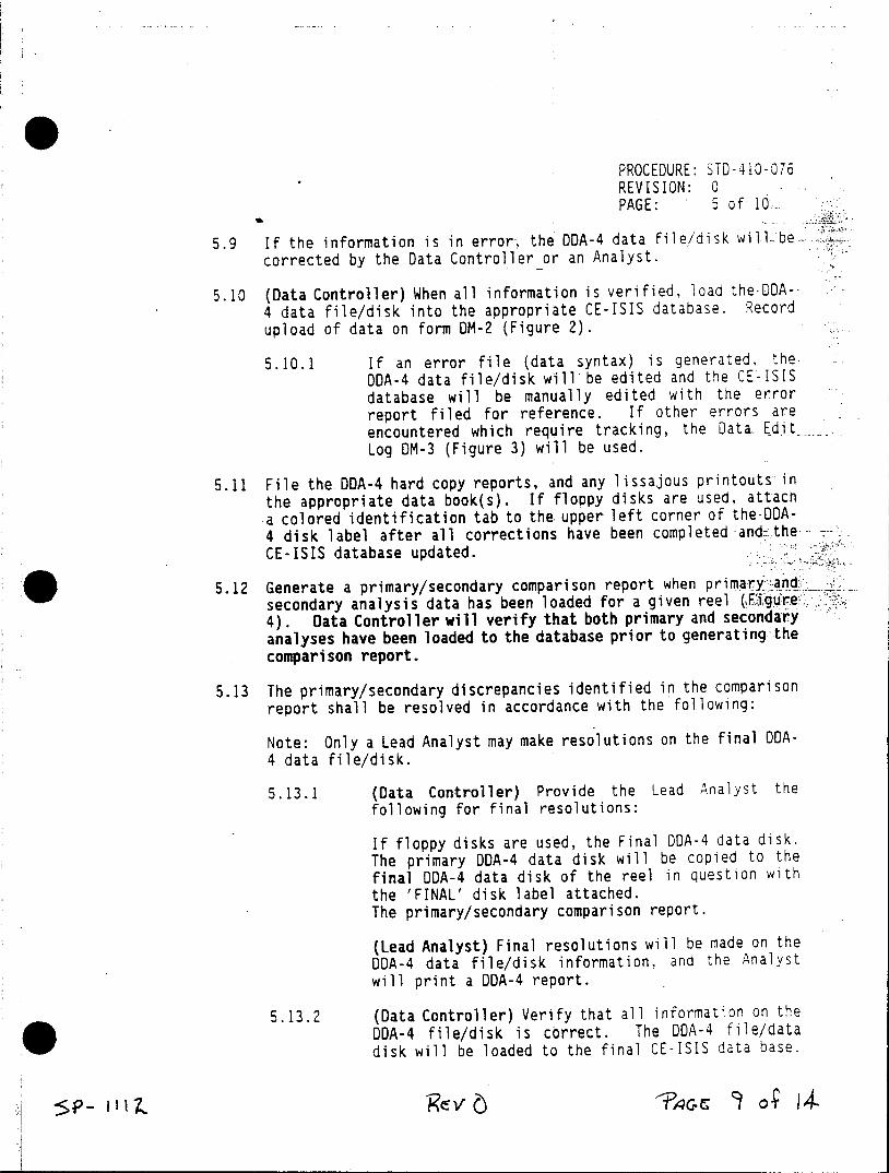
PROCEDURE: STD-410-076 REVISION: 0 PAGE: 5 of 10
5.9 If the information is in error, the ODA-4 data file/disk will- be corrected by the Data Controller or an Analyst.
5.10 (Data Controller) When all information is verified, load the DDA4 data file/disk into the appropriate CE-ISIS database. Record upload of data on form OM-2 (Figure 2).
5.10.1 If an error file (data syntax) is generated, the. DDA-4 data file/disk will be edited and the CE-ISIS database will be manually edited with the error report filed for reference. If other errors are encountered which require tracking, the Data EditLog DM-3 (Figure 3) will be used.
5.11 File the DDA-4 hard copy reports, and any lissajous printouts in the appropriate data book(s). If floppy disks are used, attach a colored identification tab to the upper left corner of the-DA4 disk label after all corrections have been completed and the CE-ISIS database updated.
5.12 Generate a primary/secondary comparison report when primary and secondary analysis data has been loaded for a given reel (Figure 4). Data Controller will verify that both primary and secondary analyses have been loaded to the database prior to generating-the comparison report.
5.13 The primary/secondary discrepancies identified in the comparison report shall be resolved in accordance with the following:
Note: Only a Lead Analyst may make resolutions on the final ODA4 data file/disk.
5.13.1 (Data Controller) Provide the Lead Analyst the following for final resolutions:
If floppy disks are used, the Final DDA-4 data disk. The primary 0DA-4 data disk will be copied to the final DDA-4 data disk of the reel in question with the 'FINAL' disk label attached. The primary/secondary comparison report.
(Lead Analyst) Final resolutions will be made on the DDA-4 data file/disk information, and the Analyst will print a DDA-4 report.
5.13.2 (Data Controller) Verify that all information on the DDA-4 file/disk is correct. The DOA-4 file/data disk will be loaded to the final CE-ISIS data base.
PROCEDURE: STD-410-076 REVISION: 0 PAGE: 6 of 0
6.0 REPORTING CRITERIA
6.1 Reporting of accumulated eddy cur-rent data shall be performed by the Data Controller or a properly trained designee. Dai. y reports and final reports will be generated in a timely fashion according to customer requests. Report formats may- be established before the outage begins, or during the outage to meet customer specific requirements. Generating reports does not affect the data in the database, therefore no editing. documentation is required for reports to be generated. Logs of reports and other printouts generated may be used to track reporting of ISIS data.
II)
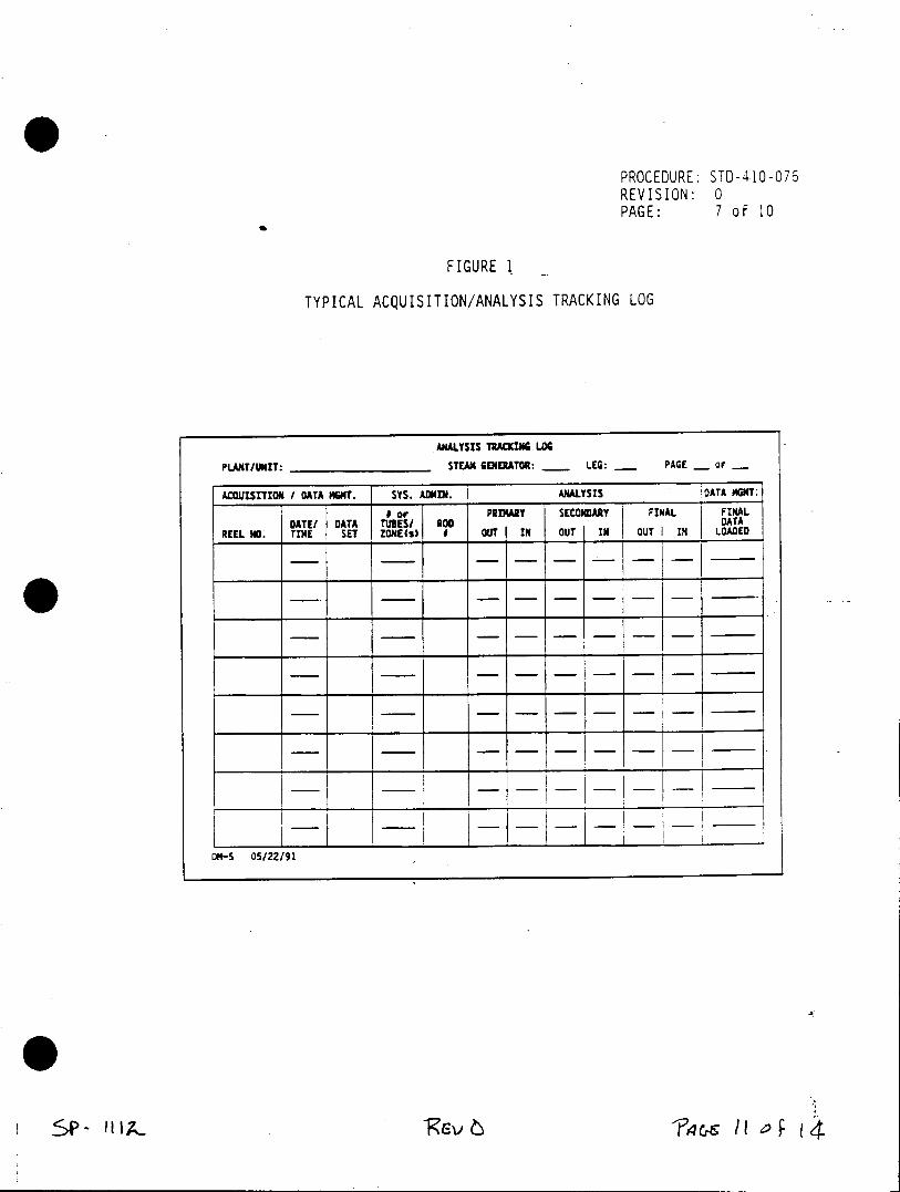
PROCEDURE: STD-410-076 REVISION: 0 PAGE: 7 of 10
FIGURE 1
TYPICAL ACQUISITION/ANALYSIS TRACKING LOG
ANALYSIS TRACKING LOG
PLANT/UNIT: STEAM GENERATOR: - LEG: PAGE OF
ACOUISITION / OATA MGMT. SYS. ADMIN. ANALYSIS DATA MGMT:
9 or PRIMARY SECONDARY FINAL FINAL DATE/ DATA TUBES/ RO DATA
REEL NO. TIME SET ZONE(s) I OUT IN OUT IN OUT IN LOADED
DM-5 05/22/91
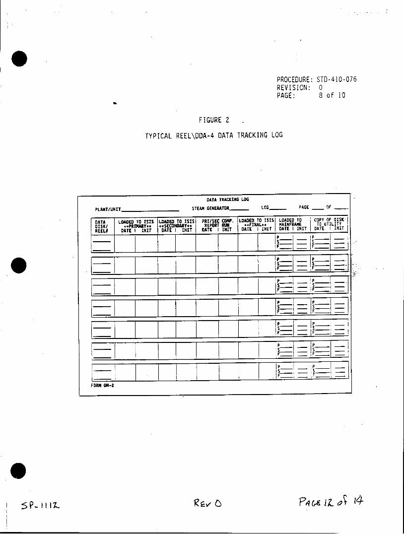
PROCEDURE: STD-410-076 REVISION: 0 PAGE: 8 of 10
FIGURE 2
TYPICAL REEL\DDA-4 DATA TRACKING LOG
DATA TRACKING LOG
PLANT/UNIT STEAM GENERATO - LEG PAGE OF
DATA LOADED TO ISIS LOADED TO ISIS PRI/SEC COMP. LOADED TO ISIS LOADED TO COPY OFOSKj DISK/ **PRIMAY** **SECONDARY** REPORT RUN **FINAL.* MAINFRAME TO UTILITY REELI DATE I INIT DATE I INIT DATE I INIT DATE I INIT DATE I INIT DATE I INIT
F~ j !F
__ 1 Is~
FORM DM-2
I'
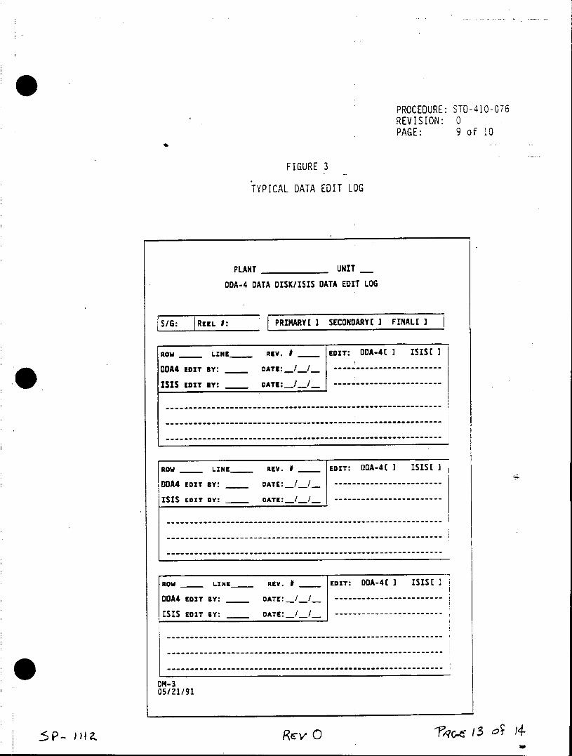
PROCEDURE: STD-410-076 REVISION: 0 PAGE: 9 of 10
FIGURE 3
TYPICAL DATA EDIT LOG
PLANT UNIT
DDA-4 DATA DISK/ISIS DATA EDIT LOG
SIG: REEL #: 1 PRIMARY[ I SECONDARY[ I FINALE I
ROW _ LINE REV. # EDIT: DOA-41 I ISIS[ I
DDA4 EDIT BY: DATE: __/_I..-/-
ISIS EDT mY: DATE: I -
------------------------------------------------------------------------
------------------------------------------------------------------------
------------------------------------------------------------------------
ROW _ LNE REV. # ____ EDIT: DA-4( I ISIST I
DDA4 EDIT BY: DATE: __/ /
ISIS EDIT BY: DATE: -/ -----------
------------------------------------------------------------------------
------------------------------------------------------------------------
ROW _ LINE _ REV. I___EDIT: ODA-4E I I5SSt
DDA4 EDIT mY: DATE: -----I-------I
ISIS EDIT BY: DATE: -- -- - -- -- - -- --
DM-3 05/21/91
RevO 4c 3 of 14
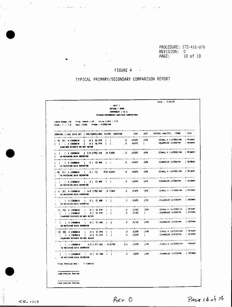
PROCEDURE: STD-410-076 REVISION: 0 PAGE: 10 of 10
FIGURE 4
TYPICAL PRIMARY/SECONDARY COMPARISON REPORT
oare 9/25/89
UNIl I WTAGE : 8909 CPUcNENT : S0 C
PItItNA/ECOARY AALTSIS CDIPllS
oeptn ange :10 Plug. Deth : 40 Volts Limit : 5.0
Enwl. 1.0 e*L :C0O6 Prone : A720F/MIN
..........................................................................................................................
IRWICOL I LEGI DATA SET I 90LTSIDEGIleS. ICHNI LOCATIN ERI CIT . TESTEDI ANALYSTI PROBE 'AT&
..........................................................................................................................
1 9I 31| a CC I M: | .0 1 j 0 tt I | .0 .0107C 107N .01 HALL IIA7205FIRM I PeIMAs
1 N (CSMiN j .0 | 30 ATR I .0 .0107C I .0|unEIER4 AI20SFEN I suanon
EiAMfIiED EVENTS 00 OT MAICO ........................................................................................................... .... ...........
I A iCta:. 1 2.9 11791 INS Io 113 -.2 .0107C 107N QIMIALL t I IZZOSF/iS I nitimr
N PAICKING DATA hIEPOf IC ............................................................
IN l2cass 1 .0 1 01 wo I I .0 .0107 107N .OWIEKLE4 1Al203A | 5ECONDA
S 0 MtACKING DATA REPOTED ..... ... ................... ............. ........ ................ ..................... .............. .......... ... ..........
| 181 311 a ICuaI 1 .3 1 0 KIN 21Av3 .0 .0107C |07C .0IALL 4 IA7205tita I m:MMI I N- maCI DATA sEPOTED
............................................... ................... ..................... .............. .......... ... ..........
I ICIl 1 .0 I 01 MDO I 1 .0 .0107 7OTC .01AEELLR IlA205Fan I SECONaA
NO MaICING DATA REPORIED .............................................................................................. .............................
: 41 321 K ICO o 6.9 1171 OhT IQ MOD | .0 QIO0C |T7C OALL I IIA720SFR/ I |SCNAY
I 0 MATCHING DATA REPORTED .................................................... . . .................... ................. .....
................................................................................................................. ...........
9| 321 a IC8a81 .0 | 01 RIT I .0 .3|TEC 07N .011ALL £ i4770SFInI PaInAI
I I C 1Icos I .0 1 01 KT I I .0 .017EC I .0IWMEILER IA72OSF#M 1SE:04
EXAMIMED Exiters 00 ImDI RATCm ............................................................................................................................
I | ICUCalIg | .0 1 0| moo I .0 O0TEC Jon .0|WIELN IA720SFaN I SCONA
Il10 TCHING DATA REPORTED ............................................ :....................................................................... ........
91 331 A IC08ia 1 .0 1 0oN I 1 0 Ol1ft 107N OIPALL ( l|AT20SY/K P RIMARY
K 5C3OhIm I .0 .0 07 j .0 000C E .IWELER IA720SFRN j SE:0OA
EXAMIMED EXTENTS 00 NT MIATCE ... ....................................................................................................................
|N |CaNE8 1 6.3 | 211 ORI N $|IE 2.4 .0107C |370 .0 NALL K IJA72OSF/sW 'RINsAK
40 WITCHING CATA REPORIED ............................................................................................................................
N 4 ICB0his 1 .0 1 0 NOD 1 .0 .0107C 137H .0YNEELER JA720SFN I SECONA
N0 SATCHING QATA REPOITED
Total kneolutions 5 Tube(s)
Lead Analyst RevieK
Lead Afalyst Review
CAROLINA POWER AND LIGHT COMPANY H.B. ROBINSON SEG PLANT
SPECIAL PROCEDURE
SP-1113
REMOTE INSTALLATION, CALIBRATION AND REMOVAL OF SM-10/20 MANIPULATOR
REVISION 0 CONTROLLED RECIPIENT
Effective Date I Expiration Date /_ _ _
RECOMMENDED BY: ___ _____4_-__ __2.
Sujervisor - Technical Support Date
APPROVED BY: A/ Manage - Technica Support D e
SP-1113 REV 0 PAGE 1 of 25
LIST OF EFFECTIVE PAGES
EFFECTIVE PAGES REVISION
Cover Sheet 0
LEP 0
3 through 25 0
SP-1113 REV 0 PAGE 2 of 25
TABLE OF CONTENTS
SECTION TITLE
1.0 Prerequisites
2.0 Precautions
3.0 Attachment
3.1 Remote Installation, Calibration and Removal of SM-10/20 Manipulator
4.0 Disposition of Records
SP-1113 REV 0 PAGE 3 of 25
1.0 PREREQUISITES
Ensure individuals are on an appropriate RWP if work is to be performed inside the Radiation Control Area.
This procedure has been reviewed per PLP-037 and it has been determined NOT to be applicable.
Unit / Section Manager Date
2.0 PRECAUTIONS
Use the principles of ALARA in planning and performing work and operations in the Radiation Control Area.
3.0 ATTACHMENT
3.1 Remote Installation, Calibration and Removal of SM-10/20 Manipulator
4.0 DISPOSITION OF RECORDS
A copy of this procedure and the completed attachments shall be sent to the records vault for storage.
SP-1113 REV 0 PAGE 4 of 25
e4cuIm~ro 3*
REMOTE INSTALLATION, CALIBRATION AND REMOVAL, OF SM-10/20 MANIPULATOR
PROCEDURE NO.
STD-410-075
Revision 1
ABB COMBUSTION ENGINEERING NUCLEAR SERVICES
APPROVED BY: DATE: Q ity Qperations
APPROVED BY: 09a7/ Z , z IAZ DATE: Z / V 97 Cognizant Supervisor
Procedure: STD-410-075 Revision: 1
Page: 2 of 21
TABLE OF CONTENTS
SECTION TITLE
1.0 OBJECTIVE
2.0 REFERENCE
3.0 PREREQUISITE AND PRECAUTIONS
4.0 PROCEDURE: INSTALLATION AND SET-UP
5.0 CALIBRATION OF FIXTURE
6.0 INSPECTION PLAN EXAMINATIONS
7.0 MANUAL OPERATION EXAMINATIONS
8.0 REMOVAL OF FIXTURE
9.0 EMERGENCY REMOVAL OF FIXTURE
10.0 COMPUTER LOCK-UP RECOVERY
I P C. C
Procedure: STD-410-075 Revision: 1
Page: 3 of 21
1.0 OBJECTIVE
1.1 This procedure provides the general instruction for Installation, Calibration and Removal of the SM-10/20 Manipulator. Actions are the same for the SM-10 and the SM-20 except where noted.
2.0 REFERENCE
2.1 ZETEC SM-10/20 Installation and Operating Guide
2.2 ZETEC SM-10/20 Inspection Planning System
2.3 NPB Nuclear Quality Assurance Manual, QAM-100, Third Edition, Revision 3.
3.0 PREREQUISITE
3.1 Steam generator primary manway cover(s) and stud bolts have been removed (as required).
3.2 The steam generator shall be at an acceptable level of dryness.
3.3 Prior to installation, the steam generator channel heads, should be cooled down to a proper temperature to prevent heat damage to equipment (approximately 90 degrees F).
3.4 Provisions must be made for personnel and equipment entry into and exit from the steam generator (i.e., ladders, scaffolds, or staging platform, lighting inside and outside the steam generator, breathing air supply, 120 VAC electricity, etc.).
3.5 An area near the steam generator suitable for the setup and installation of the equipment will be made available and cleared.
3.6 Nozzle covers have been installed over the hot and coldleg nozzles of opened channel heads (as required).
3.7 It is expected that very high levels of radiation will be encountered inside and adjacent to the primary head of the steam generators. Utmost care shall be taken in the set-up and performance of the examination to minimize personnel exposure to ionizing radiation and radioactive contamination.
cr V,_~c
Procedure: STD-410-075 Revision: 1
Page: 4 of 21.
Personnel engaged in the eddy current examination program shall be indoctrinated in the radiation protection rules, guidelines, protective clothing andequipment requirements in effect at the plant site.
4.0 PROCEDURE: INSTALLATION AND SET-UP
4.1 General Outline
4.1.1 The installation and set-up for the SM-10/20 will involve hooking up fixture cables to the appropriate locations on the SM-10/20 control box; booting the MIZ-18 ACQUISITION and FIXTURE CONTROL software and loading an INSPECTION PLAN; mounting the trunk assembly to the manway; setting an encoder offset; installing the arm assembly; installing the guide tube with conduit attached; and leveling the arm assembly inside the steam generator.
4.2 Computer Interface
4.2.1 It is good practice to remove power from all instruments, with the exception of the controlling computer, when connecting or disconnecting cables.
4.2.2 The SM-10/20 can operate with or without the MIZ-18 eddy current instrument. When operating alone, connect the interface cable, P/N 5-8103, directly to the SM-10/20 computer connector. Several interface cables, up to 1000 feet total length, can connect in series to the HPIB Interface Unit, which is located within 10 feet of the computer. The Interface Unit then uses a standard IEEE 488 cable to connect to the computer.
4.2.3 When operating in conjunction with the MIZ18, the two instruments are "daisy-chained" in series. Either unit can be closer to the computer. The 1st unit in series uses the computer connector to connect the computer, and the auxiliary connector of the 2nd unit in series will not be used. Any length cable can separate the two instruments, as long as the 2nd unit in series is not more than 1000 feet from the computer.
5P- 1113 0Rey
Procedure: STD-410-075 Revision: 1
Page: 5 of 21
4.3 Fixture Interface
4.3.1 The SM-10/20 Controller can be located up to 100 feet from the fixture. It is connected with extension cables, which can be "daisychained" as required.
4.3.2 Connect the three connectors of the extension cable assembly, P/N 4-008005, to the encoder, motor, and trunk connectors on the SM-10/20. Connect the opposite end of the cable to the encoder and motor connectors on the fixture harness, and to the trunk connector, located on the manway mount.
4.4 Video
4.4.1 Connect the video monitor with coaxial cable to the monitor connector on the controller. The fixture camera is connected via the motor connector.
4.4.2 Should it be required to use a camera separate from the one located on the fixture, an auxiliary camera input is available on the controller. When using this input, the fixture camera will need to be disconnected.
4.5 Powering Up
4.5.1 Assure that the 115/230 V selector plug is in the proper orientation.
4.5.2 Plug unit in. There is no power switch.
4.5.3 Turn on HPIB Interface Unit. SM-10/20 is now
ready for computer control.
4.6 Initial Check-Out
4.6.1 Place a 200/300 Series Acquisition System disk in disk drive 0 and close the drive door. For the HP 9836, this is the INTERNAL RIGHT DRIVE. For the HP 300 series computers using external drives, the disk drives should be appropriately marked as '0' or '1'.
4.6.2 Apply power to all components of the system.
Cv
Procedure: STD-410-075 Revision: 1
Page: 6 of 21
4.6.3 Insert the SM-10/20 Control Supplement disk in drive 1. Press LOAD ENTRY key. After the disk has loaded, remove the SM-10/20 Control Supplement (the Acquisition System Disk: remains in drive 0). Press TEST.
4.6.4 Insert the Inspection Plan Map disk in drive 1. Press FIXTURE, then LOAD PLAN (SHIFTED). The message 'INSPECTION PLAN LOADED' will appear after the plan has been loaded (the Inspection Plan Map disk will remain in drive 1).
4.6.5 Press FIX CNTRL, then manual (shifted). Press FREE RUN (SHIFTED).
4.6.6 Using the LIFT, ARM and POLE soft-keys, ensure that the motors operate correctly. Verify proper camera focus with the guide tube prior to performing step 4.6.7.
NOTE: Normally this "check-out" sequence is done in an area away from the steam generators, and afterward the fixture is carried up to the platform for installation.
4.6.7 Fold the camera arm up.over the pole, until it reaches its mechanical limit. To facilitate guide tube pick-up at a later time, it is critical to ensure that the arm is folded in such a way that it will be able to rotate towards the divider plate after installation (e.g.,-if the divider plate is to the left of the manway, the arm should be able to rotate clockwise from the mechanical stop; if the divider plate is to the right of the manway, the arm should be able to rotate counterclockwise from the mechanical stop).
4.6.8 Turn OFF the HPIB Interface Unit and leave OFF for 10 Seconds. Turn ON the HPIB Interface Unit. The red LED on the camera will light and the video will be present on the monitor.
4.6.9 NOTE: Turning power off on the HPIB
5jR ff6V
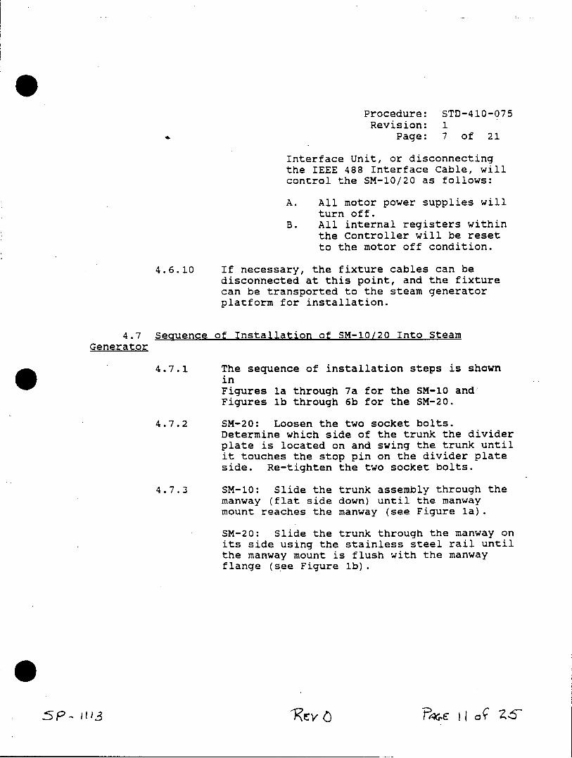
Procedure: STD-410-075 Revision: 1
Page: 7 of 21
Interface Unit, or disconnecting the IEEE 488 Interface Cable, will control the SM-10/20 as follows:
A. All motor power supplies will turn off.
B. All internal registers within the Controller will be reset to the motor off condition.
4.6.10 If necessary, the fixture cables can be disconnected at this point, and the fixture can be transported to the steam generator platform for installation.
4.7 Sequence of Installation of SM-10/20 Into Steam Generator
4.7.1 The sequence of installation steps is shown in Figures la through 7a for the SM-10 and Figures lb through 6b for the SM-20.
4.7.2 SM-20: Loosen the two socket bolts. Determine which side of the trunk the divider plate is located on and swing the trunk until it touches the stop pin on the divider plate side. Re-tighten the two socket bolts.
4.7.3 SM-10: Slide the trunk assembly through the manway (flat side down) until the manway mount reaches the manway (see Figure la).
SM-20: Slide the trunk through the manway on its side using the stainless steel rail until the manway mount is flush with the manway flange (see Figure lb).
'Re *n Y4 I I ' Z6
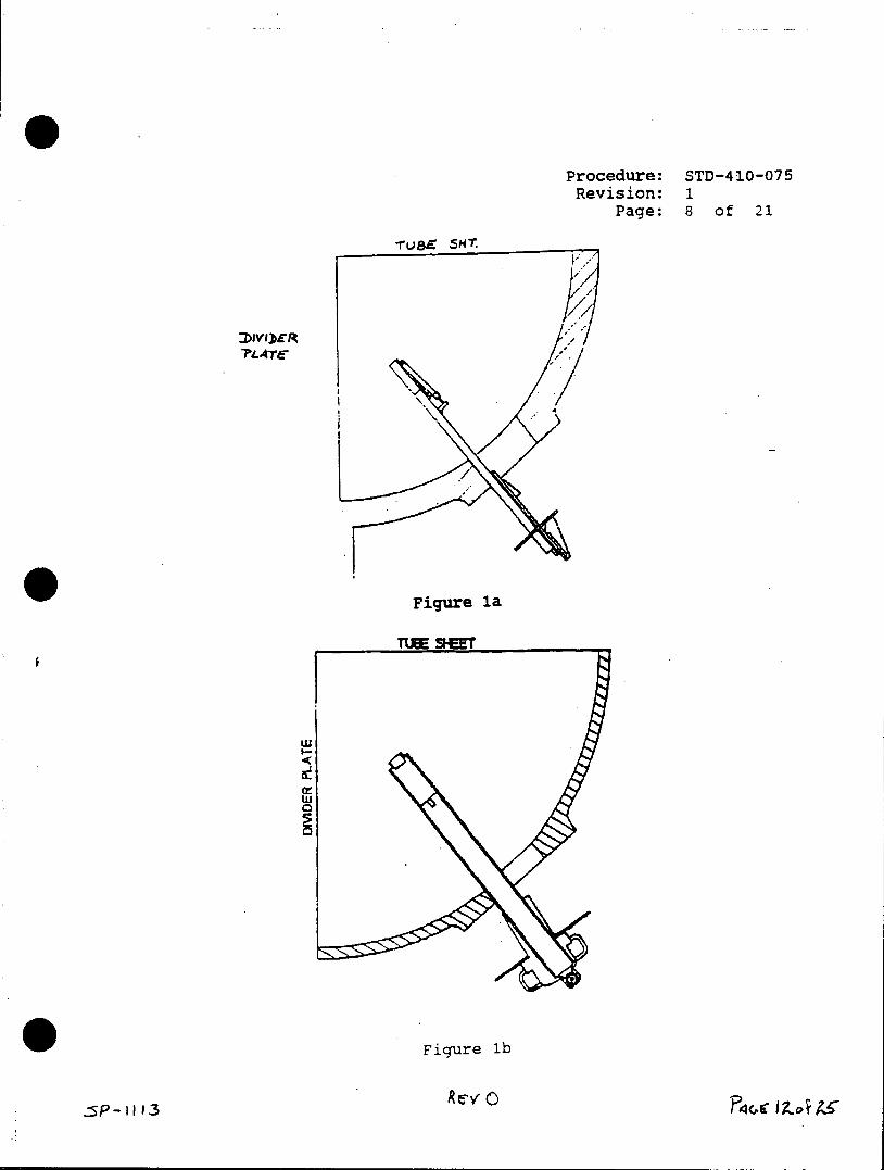
Procedure: STD-410-075 Revision: 1
Page: 8 of 21
Tvat 5H
7LATEA
Figure la
TUBE SHET
O w
Figure lb
sP-) 1'3 Rev
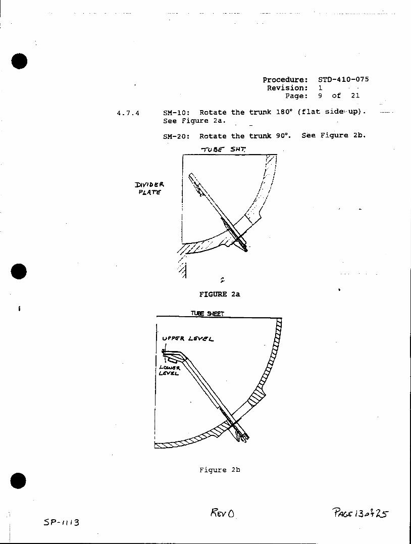
Procedure: STD-410-075 Revision: 1
Page: 9 of 21
4.7.4 SM-10: Rotate the trunk 1800 (flat side up). See Figure 2a.
SM-20: Rotate the trunk 900. See Figure 2b.
*1USEfr SMT
PLATY 1
FIGURE 2a
I TUHE SHEE
UJPPVR LE.VEL..
Figure 2b
SP-u '3
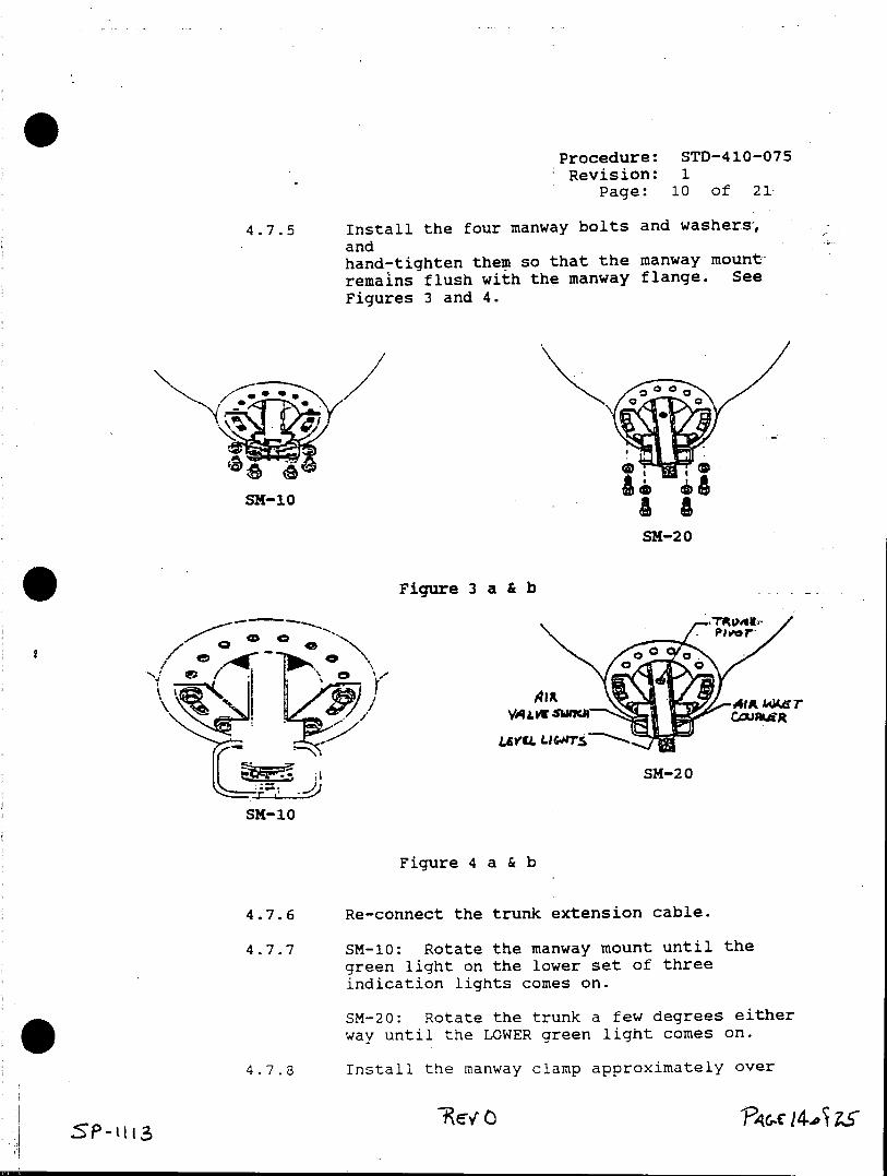
Procedure: STD-410-075 Revision: 1
Page: 10 of 21
4.7.5 Install the four manway bolts and washers, and hand-tighten them so that the manway mount remains flush with the manway flange. See
Figures 3 and 4.
SM1
SM-20
Figure 3 a & b
VA e Cc"
SM-20
SM-10
Figure 4 a & b
4.7.6 Re-connect the trunk extension cable.
4.7.7 SM-10: Rotate the manway mount until the green light on the lower set of three indication lights comes on.
SM-20: Rotate the trunk a few degrees either way until the LOWER green light comes on.
4.7.8 Install the manway clamp approximately over
SP-1H34p ZS
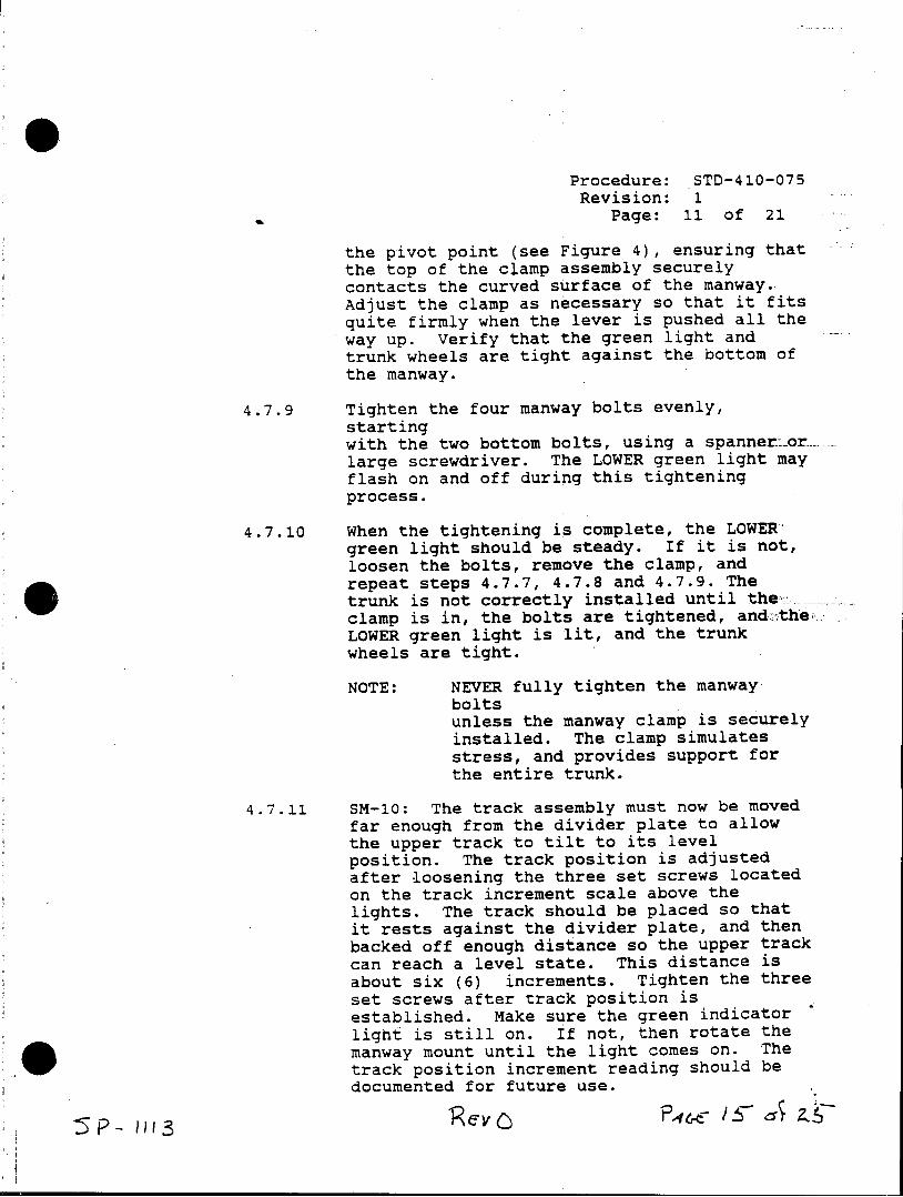
Procedure: STD-410-075 Revision: 1
Page: 11 of 21
the pivot point (see Figure 4), ensuring that the top of the clamp assembly securely contacts the curved surface of the manway. Adjust the clamp as necessary so that it fits quite firmly when the lever is pushed all the way up. Verify that the green light and trunk wheels are tight against the bottom of the manway.
4.7.9 Tighten the four manway bolts evenly, starting with the two bottom bolts, using a spanner.orlarge screwdriver. The LOWER green light may flash on and off during this tightening process.
4.7.10 When the tightening is complete, the LOWER green light should be steady. If it is not, loosen the bolts, remove the clamp, and repeat steps 4.7.7, 4.7.8 and 4.7.9. The trunk is not correctly installed until the clamp is in, the bolts are tightened, andthe LOWER green light is lit, and the trunk wheels are tight.
NOTE: NEVER fully tighten the manway bolts unless the manway clamp is securely installed. The clamp simulates stress, and provides support for the entire trunk.
4.7.11 SM-10: The track assembly must now be moved far enough from the divider plate to allow the upper track to tilt to its level position. The track position is adjusted after loosening the three set screws located on the track increment scale above the lights. The track should be placed so that it rests against the divider plate, and then backed off enough distance so the upper track can reach a level state. This distance is about six (6) increments. Tighten the three set screws after track position is established. Make sure the green indicator light is still on. If not, then rotate the manway mount until the light comes on. The track position increment reading should be documented for future use.
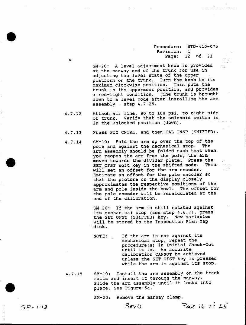
Procedure: STD-410-075 Revision: 1
Page: 12 of 21
SM-20: A level adjustment knob is provided at the manway end of the trunk for use in adjusting the level-state of the upper platform on the trunk. Turn the knob to its maximum clockwise position. This puts the trunk in its uppermost position, and provides a red-light condition. (The trunk is brought down to a level mode after installing the arm assembly - step 4.7.25.
4.7.12 Attach air line, 80 to 100 psi, to right side of trunk. Verify that the solenoid switch is in the unlocked position (down).
4.7.13 Press FIX CNTRL, and then CAL INSP (SHIFTED).
4.7.14 SM-10: Fold the arm up over the top of the pole and against the mechanical stop. The arm assembly should be folded such that when you reopen the arm from the pole, the arm moves towards the divider plate. Press theSET OFST soft key in the shifted mode. This wilf set an offset for the arm encoder. Estimate an offset for the pole encoder so that the picture on the display closely approximates the respective positions of the arm and pole inside the bowl. The offset for the pole encoder will be recalculated at the end of the calibration.
SM-20: If the arm is still rotated against its mechanical stop (see step 4.6.7), press the SET OFST (SHIFTED) key. New variables will be stored to the Inspection Plan Map disk.
NOTE: If the arm is not against its mechanical stop, repeat the procedure(s) in Initial Check-Out until it is.. An accurate calibration CANNOT be achieved unless the SET OFST key is pressed while the arm is against its stop.
4.7.15 SM-10: Install the arm assembly on the track rails and insert it through the manway. Slide the arm assembly until it locks into place. See Figure 5a.
SM-20: Remove the manway clamp.
Keyw F)v ?,6. a( O z
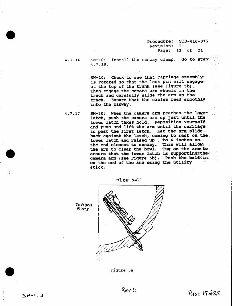
Procedure: STD-410-075 Revision: 1
Page: 13 of 21
4.7.16 SM-10: Install the manway clamp. Go to step 4.7.18.
SM-20: Check to see that carriage assemblyis rotated so that the lock pin will engage-at the top of the trunk (see Figure 5b). Then engage the camera arm wheels in the track and carefully slide the arm up the track. Ensure that the cables feed smoothly into the manway.
4.7.17 SM-20: When the camera arm reaches the lower latch, push the camera arm up just until. the lower latch takes hold. Reposition yourself and push and lift the arm until the carriage is past the first latch. Let the arm slideback against the latch, coming to rest on-the lower latch and raised up 3 to 4 inches-on the end closest to manway. This will allow,. the arm to clear the bowl. Tug on the arm to ensure that the lower latch is supporting the camera arm (see Figure 5b). Push the bal@ in on the end of the arm using the utility stick.
FuArE
* Figure 5a
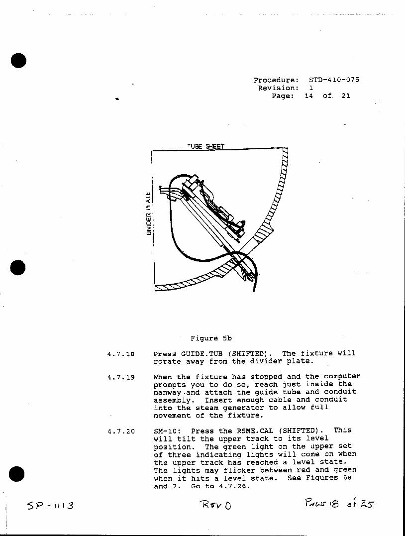
Procedure: STD-410-075 Revision: 1
Page: 14 of. 21
UBE -5HEET
Figure 5b
4.7.18 Press GUIDE.TUB (SHIFTED). The fixture will rotate away from the divider plate.
4.7.19 When the fixture has stopped and the computer prompts you to do so, reach just inside the manway.and attach the guide tube and conduit assembly. Insert enough cable and conduit into the steam generator to allow full movement of the fixture.
4.7.20 SM-10: Press the RSME.CAL (SHIFTED). This will tilt the upper track to its level position. The green light on the upper set of three indicating lights will come on when the upper track has reached a level state. The lights may flicker between red and green when it hits a level state. See Figures 6a and 7. Go to 4.7.26.
Procedure: STD-410-075 Revision: 1
Page: 15 of 21
Caution: If the upper track has been raised manually above the level position, the upper trac)k will raise until the guide tube makes contact with the tube sheet. The track must then be lowered below the level position before leveling may begin.
SM-20: Press GT.ON. The fixture will fold itself back up over the trunk so that it can be moved upward into the top latch.
4.7.21 SM-20: When the fixture stops, attach the utility stick to the ball stud located on the end of the camera arm. Be sure that the utility stick is securely attached.
4.7.22 SM-20: Push the arm up and over the curved ramp until it latches securely in the top latch. The camera arm should be parallel to the tubesheet.
4.7.23 SM-20: Activate the air solenoid to lock the camera arm in position. The switch should be toggled to the "LOCK" position.
4.7.24 SM-20: Remove the utility stick from the camera arm.
4.7.25 SM-20: Install the manway clamp. Pass sufficient cabling and.conduit through the manway at this time (Figure 6b). We recommend running the cables and conduit on the side of the manway clamp which is opposite the divider plate. Then rotate the leveling knob counter-clockwise until the upper red light goes out and the upper green light comes on.
4.7.26 Proceed with the calibration process.
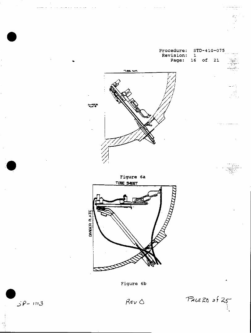
Procedure: STD-410-075 Revision: 1
Page: 16 of 21
Figure 6a
Sevi
w/
i 6
Figure 6b
j~Ev 6 3
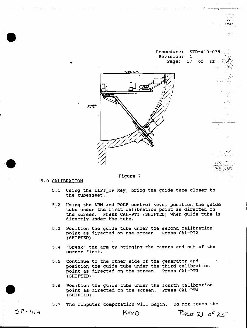
Procedure: STD-410-075 Revision: 1
Page: 17 of 21,
Figure 7 5.0 CALIBRATION
5.1 Using the LIFTUP key, bring the guide tube closer to the tubesheet.
5.2 Using the ARM and POLE control keys, position the guide tube under the first calibration point as directed on the screen. Press CAL-PT1 (SHIFTED) when guide tube is directly under the tube.
5.3 Position the guide tube under the second calibration point as directed on the screen. Press CAL-PT2 (SHIFTED).
5.4 "Break" the arm by bringing the camera end out of the corner first.
5.5 Continue to the other side of the generator and position the guide tube under the third calibration point as directed on the screen. Press CAL-PT3 (SHIFTED).
5.6 Position the guide tube under the fourth calibration point as directed on the screen. Press CAL-PT4 (SHIFTED).
5.7 The computer computation will begin. Do not touch the
"'3 1 4C~cr~ zso
Procedure: STD-410-075 Revision: 1
Page: 18 of: 21
keyboard during this time.
5.8 When the computation is complete, the current fixture position is displayed, and the keys necessary for commencing the inspection are available.
6.0 INSPECTION PLAN EXAMINATIONS
6.1 Store variables to all Insp-Plan disks for that specific steam generator by pressing STORE.VAR (SHIFTED).
6.2 Press the upper left soft key labeled NOFIXTURE (SHIFTED) until TEST-PLAN is displayed.
6.3 Press MIZ-18 ON.
6.3.1 Press START COL: (SHIFTED) to begin examination by columns.
6.3.2 Press START ROW: (SHIFTED) to begin examination by rows.
6.3.3 Examine the first tube.
6.3.4 After examining each tube, press NEXTTUB.
6.3.5 Verify that the guide tube is centered under each tube to- be examined. Peripheral tubes, plugs and stays should be used for continuous verification of the manipulator.
6.3.6 To stop an inspection plan press STOPINSP (SHIFTED).
6.4 If there is more than on Insp-Plan, place the next Insp-Plan disk in the left drive. Return to Insp-Plan mode and load it by pressing LOAD.PLAN (SHIFTED). Repeat steps 6.3.1 through 6.3.6.
7.0 MANUAL OPERATION EXAMINATIONS
7.1 Turn MIZ-18 off. Press FIXTURE soft key.
7.2 Press the upper left soft key (SHIFTED) until MANUAL is displayed and manual tube selection has been initiated.
7.3 Turn the MIZ-18 on and use soft keys ROW +, ROW -, COL +, and COL - to select the next tube to be examined.
m3 RIFY3L)
Procedure: STD-410-075Revision: 1
Page: 19 of 21
7.4 Press LOCATE for automatic location of the tube by the manipulator.
7.5 Press FREE RUN for manual mode movement using the camera arm and pivot pole keys.
8.0 REMOVAL OF FIXTURE
8.1 Press FOLD UP (SHIFTED). The lift will automatically lower camera head and the arms will move to a predetermined position.
NOTE: If the arm is not on the correct side of the generator, you will be instructed to break.the arm. After doing so, press RESUME (SHIFTED) then press FOLD UP (SHIFTED) again.
8.2 When the fixture has stopped, remove the manway clamp.
SM-10: Remove guide tube. Go to step 8.7.
SM-20: Attach the utility stick to the ball stud on the end of the camera arm. Turn air solenoid switch to the "UNLOCK" position.
8.3 SM-20: Release the upper latch by pulling the release trigger on the left side of the trunk. Lift the release trigger up so that it is locked in the release mode.
8.4 SM-20: Position yourself in such a way that you can use both hands on the utility stick to carefully roll the camera arm down to the lower latch.
8.5 SM-20: Remove the utility stick from the camera arm. Press the LOWERED soft-key, which will cause the fixture to position the guide tube in front of the manway.
8.6 SM-20: When the fixture has stopped, remove the guide tube.
8.7 Press the GT.RMVD key. The fixture will fold up completely.
8.8 Reach inside the manway and grasp the end of the pole (DO NOT HOLD IT ON TOP OF THE MOTOR OR YOU WILL PINCH YOUR HAND ON THE MANWAY WHEN IT COMES DOWN THE TRUNK). With the other hand, pull the lock release ring located on the right side of the trunk. Hold the release until
J j' i13e 43vO
Procedure: STD-410-075 Revision: 1
Page: 20 of 21
the carriage is past the latch.
8.9 Slowly lower the camera arm down the trunk, making sure the cable does not hang up on the end of the trunk.
8.10 SM-10: Disconnect the fixture cables.
SM-20: Disengage the wheels from the track and set the camera arm aside. Remove trunk extension cable and air line.
8.11 Remove the manway bolts.
8.12 Rotate the trunk 900 (on edge), and slide it out of the generator.
9.0 EMERGENCY REMOVAL
The SM-10/20 fixture has been designed for removal in the event that a motor or gearbox should fail with the fixture installed.
9.1 Remove the manway clamp.
9.2 Align the camera arm assembly over the trunk.
SM-20: Attach the utility stick to the camera arm and release the upper latch (on the left side of the trunk). Turn the solenoid switch to the "UNLOCKED" position. It may be necessary to swing the arm from side to side to relax the air pistons.
9.3 Roll the camera arm down to the lower latch.
SM-20: Disconnect the utility stick from the camera arm.
9.4 If the lift assembly is up, it will be necessary to place the fixture into the approximate guide tube position. To remove the lift, loosen the draw bolt using a 1/4" nut driver. You may now slide the lift assembly away from the secondary pivot and remove it through the manway. Once the lift assembly has been removed, fold the fixture back up over the trunk.
9.5 Release the lower latch (on the right side of the trunk) and remove the camera arm from the steam generator.
Rev "'37 4
Procedure: STD-410-075 Revision: 1
Page: 21 of 21
NOTE: The primary and secondary rotation assemblies may be rotated manually in the event of a failure. If sufficient physical pressure is applied to either the primary pivot (which rotates the pole) or secondary pivot (which rotates the arm), the clutches will slip andallow free rotation of the pivot receiving the force.
10.0 COMPUTER LOCK-UP RECOVERY
10.1 Boot computer with.MIZ-18 Acquisition software with-SM--10/20 Fixture Control.
10.2 Set time and date.
10.3 Check the MIZ-18 for correct configuration.
10.4 Press FIXTURE and LOAD.PLAN (SHIFTED).
10.5 Press NOFIXTURE (SHIFTED) to get desired mode of operation (usually.TEST PLAN).
10.6 Restore index to RAM from backup disk.
10.7 Go to REVIEW mode and play back the last good entry on the TLIST.
10.8 Return to TEST mode and resume test.
*I
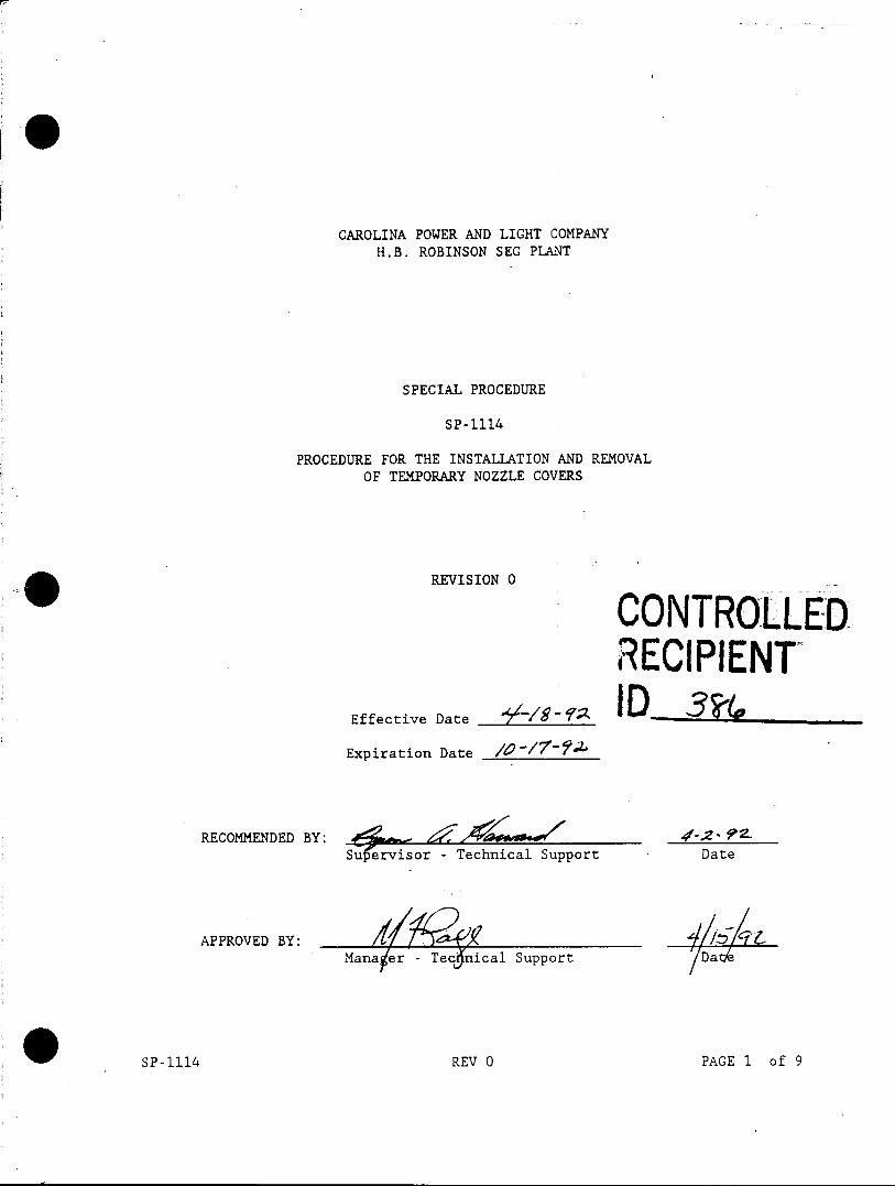
CAROLINA POWER AND LIGHT COMPANY H.B. ROBINSON SEG PLANT
SPECIAL PROCEDURE
SP-1114
PROCEDURE FOR THE INSTALLATION AND REMOVAL OF TEMPORARY NOZZLE COVERS
REVISION 0
RECIPIENT Effective Date # "D/
Expiration Date / _ _
RECOMMENDED BY: L7, 4 VaE 42-7Z Sufervisor - Technical Support Date
APPROVED BY: I/ Mana er - Tec nical Support Dat
SP-1114 REV 0 PAGE 1 of 9
LIST OF EFFECTIVE PAGES
EFFECTIVE PAGES REVISION
Cover Sheet 0
LEP 0
3 through 9 0
0 SP-1114 REV 0 PAGE 2 of 9
TABLE OF CONTENTS
SECTION TITLE
1.0 Prerequisites
2.0 Precautions
3.0 Attachment
3.1 Procedure for the Installation and Removal of Temporary Nozzle Covers
4.0 Disposition of Records
SP-1114 REV 0 PAGE 3 of 9
1.0 PREREQUISITES
Ensure individuals are on an appropriate RWP if work is to be performed inside the Radiation Control Area.
This procedure has been reviewed per PLP-037 and it has been determined NOT to be applicable.
Unit / Section Manager Date
2.0 PRECAUTIONS
Use the principles of ALARA in planning and performing work and operations in the Radiation Control Area.
The preferred method of installation is per step 6.5.2 of attachment 3.1. If this cannot be accomplished, step 6.5.3 may be used with the permission of ALARA and Technical Support personnel.
3.0 ATTACHMENT
3.1 Procedure for the installation and Removal of Temporary Nozzle Covers
4.0 DISPOSITION OF RECORDS
A copy of this procedure and the completed attachments shall be sent to the records vault for storage.
SP-1114 REV 0 PAGE 4 of 9
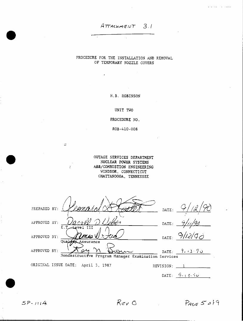
g-Tqc),"7F,1)T 3.
PROCEDURE FOR THE INSTALLATION AND REMOVAL OF TEMPORARY NOZZLE COVERS
H.B. ROBINSON
UNIT TWO
PROCEDURE NO.
ROB-410-008
OUTAGE SERVICES DEPARTMENT NUCLEAR POWER SYSTEMS
ABB/COMBUSTION ENGINEERING WINDSOR, CONNECTICUT
CHATTANOOGA, TENNESSEE
?REPARED BY:
APPROVED BY: -7 DATE:
APPROVED BY: DATE: Qua Assurance
APPROVED BY: DATE. Nonci s ruccz've Program Manager ExamiaonSrce
ORIGINAL ISSUE DATE: April 3, 1987 REVISION:
DATE:
RDATE:o-y3
PROCEDURE NO.:. ROB-410-008 REVISION NO: 1 PAGE: 2 OF 5
TABLE OF CONTENTS
SECTION TITLE
1.0 OBJECTIVE
2.0 REFERENCES
3.0 PERSONNEL REQUIREMENTS
4.0 PRECAUTIONS AND PREREQUISITIES
5.0 EQUIPMENT
6.0 INSTALLATION OF NOZZLE COVERS . 7.0 CLEANLINESS VERIFICATION
8.0 NOZZLE COVER REMOVAL
m4-2 Ro -4r,
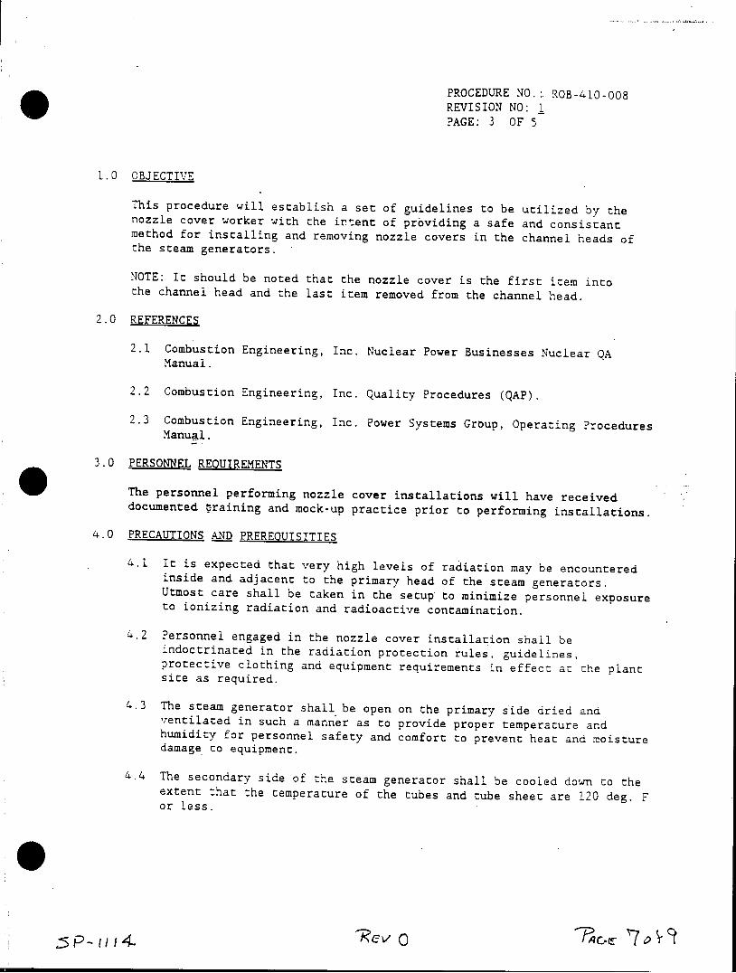
PROCEDURE NO.:. ROB-410-008 REVISION NO: L PAGE: 3 OF 5
1.0 OBJECTIVE
This procedure will establish a set of guidelines to be utilized by the nozzle cover worker with the intent of providing a safe and consistant method for installing and removing nozzle covers in the channel heads of the steam generators.
NOTE: It should be noted that the nozzle cover is the first item into the channel head and the last item removed from the channel head.
2.0 REFERENCES
2.1 Combustion Engineering, Inc. Nuclear Power Businesses Nuclear QA Manual.
2.2 Combustion Engineering, Inc. Quality Procedures (QAP).
2.3 Combustion Engineering, Inc. Power Systems Group, Operating Procedures Manul.
3.0 PERSONNEL REQUIREMENTS
The personnel performing nozzle cover installations will have received documented training and mock-up practice prior to performing installations.
4.0 PRECAUTIONS AND PREREOUISITIES
4.1 It is expected that very high levels of radiation may be encountered inside and adjacent to the primary head of the steam generators. Utmost care shall be taken in the setup to minimize personnel exposure to ionizing radiation and radioactive contamination.
4.2 Personnel engaged in the nozzle cover installation shall be indoctrinated in the radiation protection rules, guidelines, protective clothing and equipment requirements in effect at the plant site as required.
4.3 The steam generator shall be open on the primary side dried and ventilated in such a manner as to provide proper temperature and humidity for personnel safety and comfort to prevent heat and moisture damage to equipment.
4.4 The secondary side of the steam generator shall be cooled down to the extent that the temperature of the tubes and tube sheet are 120 deg. F or less.
'IIT
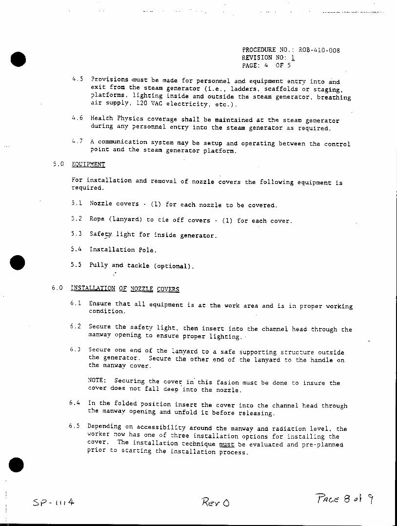
PROCEDURE NO.: ROB-410-008
REVISION NO: 1 PAGE: 4 OF 5
4.5 Provisions -must be made for personnel and equipment entry into and exit from the steam generator (i.e., ladders, scaffolds or staging, platforms, lighting inside and outside the steam generator, breathing air supply, 120 VAC electricity, etc.).
4.6 Health Physics coverage shall be maintained at the steam generator during any personnel entry into the steam generator as required.
4.7 A communication system may be setup and operating between the control point and the steam generator platform.
5.0 EQUIPMENT
For installation and removal of nozzle covers the following equipment is required.
5.1 Nozzle covers - (1) for each nozzle to be covered.
5.2 Rope (lanyard) to tie off covers - (1) for each cover.
5.3 Safety. light for inside generator.
5.4 Installation Pole.
5.5 Pully and tackle (optional).
6.0 INSTALLATION OF NOZZLE COVERS
6.1 Ensure that all equipment is at the work area and is in proper working condition.
6.2 Secure the safety light, then insert into the channel head through the manway opening to ensure proper lighting.
6.3 Secure one end of the lanyard to a safe supporting structure outside the generator. Secure the other end of the lanyard to the handle on the manway cover.
NOTE: Securing the cover in this fasion must be done to insure the cover does not fall deep into the nozzle.
6.4 In the folded position insert the cover into the channel head through the manway opening and unfold it before releasing.
6.5 Depending on accessibility around the manway and radiation level, the worker now has one of three installation options for installing the cover. The installation technique must be evaluated and pre-planned prior to starting the installation process.
TaC C m4-- Ro~o r~

PROCEDURE NO.: ROB-410-008 REVISION NO: L PAGE: 5 OF 5
6.5.1 Utilize a pole to invert the unfolded cover and push it into place over the nozzle.
6.5.2 Utilize a pully and tackle device clamped to the tubesheet from which the cover will be attached to a rope so as to lift the unfolded cover and lower it into place while guiding it with the long handle pole. After the nozzle cover is installed, remove the pully and tackle and secure the rope outside the generator.
6.5.3 Install the cover manually by entering the channel head through the manway opening. This is a generator entry and must be coordinated with Health Physics personnel.
7.0 CLEANLINESS VERIFICATION
The platform worker shall verify that all tools, equipment and debris is removed from the channel head prior to removing the nozzle cover. If any items are in the channel head, they must be removed prior to the nozzle cover removal.
8.0 NOZZLE COVER REMOVAL
8.1 Ensure the lanyard is still securely tied at both ends.
8.2 Using the rope and/or pole, pull the cover to the manway.opening.
8.3 Reach through the manway and fold up the cover.
8.4 Pull the folded cover out of the manway.
8.5 Verify that no foreign object has been left in the channel head.
SF 'II)~v ~&
NUCLEAR POWER BUSINESSES QAP 2.4 QUALITY ASSURANCE PROCEDURE REVISION 1
PAGE 1 OF 16 QAP 2.4 - CERTIFICATION PROGRAM FOR
NONDESTRUCTIVE EXAMINATION PERSONNEL -----------------------------------------------------------------------
1.0 PURPOSE
To delineate the technical requirements for qualification and certification of Levels I, II and III nondestructive examination (NDE) personnel.
2.0 REFERENCES
2.1 ASME Code, Sections I, III, V, VIII, XI and ANSI B31.1.
2.2 SNT-TC-1A - 1984, Recommended Practice for Nondestructive Testing Personnel Qualification and Certification.
2.3 Nuclear Field Quality Assurance Manual, System N-9.0.
2.4 Nuclear Spare Parts Quality Assurance Program Description, System 2.0.
2.5 QAP 17.1, Records Retention.
3.0 DEFINITIONS
3.1 Activity or Operation - Any part of a technique including but not limited to, film grading,. ultrasonic thickness examination, application of penetrant materials, evaluation of examination results, etc.
3.2 Certification - Written testimony of qualification.
3.3 Certifying Agency - The employer of the personnel being certified.
3.4 Employer - The corporate, private or public entity, which employs personnel for wages, salary, fees, or other considerations.
3.5 Method - The utilization of a physical principle in NDE in its entirety, i.e., radiography, ultrasonics, liquid penetrant, magnetic particle, eddy current, leak testing, acoustic emission, visual, etc.
3.6 Outside.Agency - A company or individual that provides NDE Level III services and whose qualifications to provide these services have been reviewed by the employer that engages the company or individual.
3.7 Qualification - The demonstrated skill, training, knowledge and experience required for personnel to properly perform the duties of a specific job.
NUCLEAR POWER BUSINESSES QAP 2.4 QUALITY ASSURANCE PROCEDURE REVISION 1
PAGE 2 OF 16 QAP 2.4 - CERTIFICATION PROGRAM FOR
NONDESTRUCTIVE EXAMINATION PERSONNEL
----------------------------------------------------------- )
3.8 Surveillance - The act of monitoring or observing to verify an item or activity conforms to specified requirements.
3.9 Technique - A specific way of utilizing a particular NDE method, i.e., gamma radiography, contact ultrasonics, solvent removable liquid penetrant examination, etc.
3.10 Training - The program developed to impart the knowledge and skills necessary for qualification.
4.0 LEVELS OF QUALIFICATION
4.1 Trainee - in the process of being qualified and certified to at least NDE Level I, an individual shall be considered a trainee. A trainee shall work with a certified individual and shall not independently conduct any test, interpret or evaluate any results of a test, or write a report of test results.
4.2 Level I .- shall be qualified to properly perform specific calibrations, specific tests and specific evaluations for acceptance or rejection according to written instructions, and to record the results. He shall receive the necessary guidance or supervision from a certified Level II or III in the same method. Those individuals performing work governed by ASME Code Section XI shall not independently evaluate or accept the results of a nondestructive examination.
4.3 Level I Limited - shall be qualified to perform only a specific activity or operation within a particular technique (e.g., application of penetrant materials, etc.).
4.4 Level II - shall be qualified to set up and calibrate equipment, and to interpret and evaluate test results with respect to applicable codes, standards and specifications. He shall be able to prepare written instructions and to organize and report nondestructive testing investigations. He shall be familiar with the scope and limitations of the method and shall exercise assigned responsibility for on-the-job training and guidance of trainees and Level I personnel.
4.5 Level II A - (Eddy Current Data Analyst for nonferromagnetic steam generator heat exchanger tubing) satisfies all the requirements for an Eddy Current Level II and in addition, is capable of interpreting and evaluating data taken from eddy current examinations of nonferromagnetic steam generator heat exchanger tubing.
NUCLEAR POWER BUSINESSES QAP 2.4 QUALITY ASSURANCE PROCEDURE REVISION 1
PAGE 3 OF 16 QAP 2.4 - CERTIFICATION PROGRAM FOR
NONDESTRUCTIVE EXAMINATION PERSONNEL -----------------------------------------------------------------------
4.6 Level II Limited - shall be qualified to perform examinations to a specific technique, activity or operation within a method, (e.g., solvent removable penetrant examination, contact ultrasonic examination, gamma radiography, film interpretation or evaluation of results of a technique or method, etc.).
4.7 Level III - shall be capable of and responsible for establishing techniques and procedures, interpreting codes, standards and specifications, and designating the particular test method and technique to be used. The individual shall be capable of evaluating results in terms of existing codes, standards, specifications and shall have sufficient practical background in applicable materials, fabrication or product technology to establish techniques and acceptance criteria where none are otherwise available. The individual shall be responsible for the training and qualification examination of NDE Levels I, II and III candidates. The actual administration and grading of examinations may be delegated in writing, to a duly selected representative of the Level III.
4.8 Certifications to the above levels of qualifications issued to NDE personnel prior to adoption of this written practice and based on an approved C-E written practice shall be considered valid for the remainder of the individual's certification period. Future certifications and recertifications shall be in accordance with this written practice.
5.0 EDUCATION, TRAINING AND EXPERIENCE
5.1 Level I and II personnel shall satisfy the education, training and experience requirements of Table 2.4-1, as modified below.
5.1.1 For a limited certification, work time experience and classroom training may be reduced for the technique, activity or operation being performed as shown in Table 2.4-2.
5.1.2 For Level IIA certification, an additional 24 hours specific training in eddy current data analysis is required to supplement the ET Level II training requirements as defined in Table 2.4-1. No additional experience is required.
0
NUCLEAR POWER BUSINESSES QAP 2.4 QUALITY ASSURANCE PROCEDURE REVISION 1
PAGE 4 OF 16 QAP 2.4 - CERTIFICATION PROGRAM FOR
NONDESTRUCTIVE EXAMINATION PERSONNEL
5.1.3 Work time experience gained while performing administrative duties shall be considered NDE experience if the duties relate to those covered by certified individuals as defined in Paragraph 4.0.
5.1.4 Limitations for individual's certified in accordance with Paragraph 5.1.1 shall be noted on their certification papers.
5.2 Level III personnel shall satisfy one of the following education and experience criteria:
5.2.1 Graduate of four (4) year accredited engineering or science college or university with a degree in engineering or science plus one (1) year experience in an assignment comparable to that of a Level II in the applicable method.
5.2.2 Completion, with a passing grade, of at least two years of engineering or science study at an accredited university, college, or technical school plus two (2) years experience comparable to that of a Level II in the applicable method.
5.2.3 Four (4) years experience comparable to that of a Level II in the applicable method.
5.3 Organized training shall be completed for all Level I and II individuals seeking certification. For Level III individuals, the training hours shall consist of at least the combined required hours for Levels I and II in the applicable method except when the candidate has been qualified or has held a position certified to that of a Level II, in which case, the requirement for training may be considered met.
5.4 To assure that an individual has assimilated the training material presented, he shall satisfy the examination requirements of Paragraph 6.0, as applicable.
5.5 Records used to substantiate education, training and experience shall be identified and maintained in accordance with Paragraph 9.0.
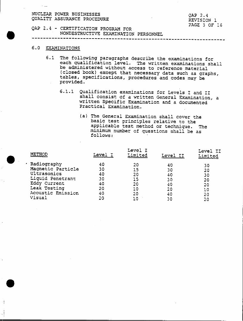
NUCLEAR POWER BUSINESSES QAP 2.4 QUALITY ASSURANCE PROCEDURE REVISION 1
PAGE 3 OF 16 QAP 2.4 - CERTIFICATION PROGRAM FOR
NONDESTRUCTIVE EXAMINATION PERSONNEL -------------------------------------------------------------
6.0 EXAMINATIONS
6.1 The following paragraphs describe the examinations for each qualification level. The written examinations shall be administered without access to reference material (closed book) except that necessary data such as graphs, tables, specifications, procedures and codes may be provided.
6.1.1 Qualification examinations for Levels I and II shall consist of a written General Examination, a written Specific Examination and a documented Practical Examination.
(a) The General Examination shall cover the basic test principles relative to the applicable test method or technique. The minimum number of questions shall be as follows:
Level I Level II METHOD Level I Limited Level II Limited
'Radiography 40 20 40 30 Magnetic Particle 30 15 30 20 Ultrasonics 40 20 40 30 Liquid Penetrant 30 15 30 20 Eddy Current 40 20 40 20 Leak Testing 20 10 20 10 Acoustic Emission 40 20 40 20 Visual 20 10 30 20
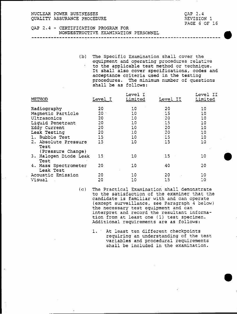
NUCLEAR POWER BUSINESSES QAP 2.4 QUALITY ASSURANCE PROCEDURE REVISION 1
PAGE 6 OF 16 QAP 2.4 - CERTIFICATION PROGRAM FOR
NONDESTRUCTIVE EXAMINATION PERSONNEL
(b) The Specific Examination shall cover the equipment and operating procedures relative to the applicable test method or technique. It shall also cover specifications, codes and acceptance criteria used in the testing procedures. The minimum number of questions shall be as follows:
Level I Level II METHOD Level I Limited Level II Limited
Radiography 20 10 20 10 Magnetic Particle 20 10 15 10 Ultrasonics 20 10 20 10 Liquid Penetrant 20 10 15 10 Eddy Current 20 10 20 10 Leak Testing 20 10 20 10 1. Bubble Test 15 10 15 10 2. Absolute Pressure 15 10 15 10
Test (Pressure Change)
3. Halogen Diode Leak 15 10 15 10 Test
4. Mass Spectrometer 20 10 40 20 Leak Test
Acoustic Emission 20 10 20 10 Visual 20 10 13 10
(c) The Practical Examination shall demonstrate to the satisfaction of the examiner that the candidate is familiar with and can operate (except surveillance, see Paragraph 4 below) the necessary test equipment and can interpret and record the resultant information from at least one (1) test specimen. Additional requirements are as follows:
1. At least ten different checkpoints requiring an understanding of the test variables and procedural requirements shall be included in the examination.
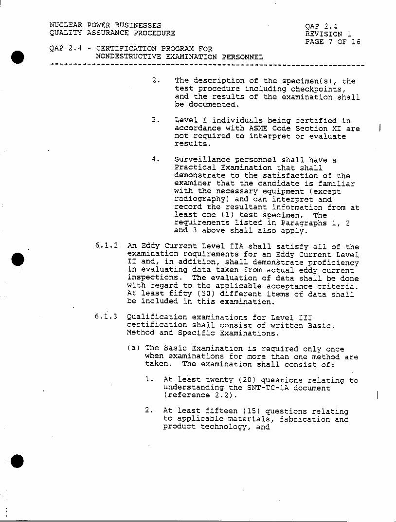
NUCLEAR POWER BUSINESSES QAP 2.4 QUALITY ASSURANCE PROCEDURE REVISION 1
PAGE 7 OF 16 QAP 2.4 - CERTIFICATION PROGRAM FOR
NONDESTRUCTIVE EXAMINATION PERSONNEL -------------------------------------- ----------- --------
2. The description of the specimen(s), the test procedure including checkpoints, and the results of the examination shall be documented.
3. Level I individuals being certified in accordance with ASME Code Section XI are not required to interpret or evaluate results.
4. Surveillance personnel shall have a Practical Examination that shall demonstrate to the satisfaction of the examiner that the candidate is familiar with the necessary equipment (except radiography) and can interpret and record the resultant information from at least one (1) test specimen. The requirements listed in Paragraphs 1, 2 and 3 above shall also apply.
6..1.2 An Eddy Current Level IIA shall satisfy all of the examination requirements for an Eddy Current Level II and, in addition, shall demonstrate proficiency in evaluating data taken from actual eddy current inspections. The evaluation of data shall be done with regard to the applicable acceptance criteria. At least fifty (50) different items of data shall be included in this examination.
6.1.3 Qualification examinations for Level III certification shall consist of written Basic, Method and Specific Examinations.
(a) The Basic Examination is required only once when examinations for more than one method are taken. The examination shall consist of:
1. At least twenty (20) questions relating to understanding the SNT-TC-1A document (reference 2.2).
2. At least fifteen (15) questions relating to applicable materials, fabrication and product technology, and
0
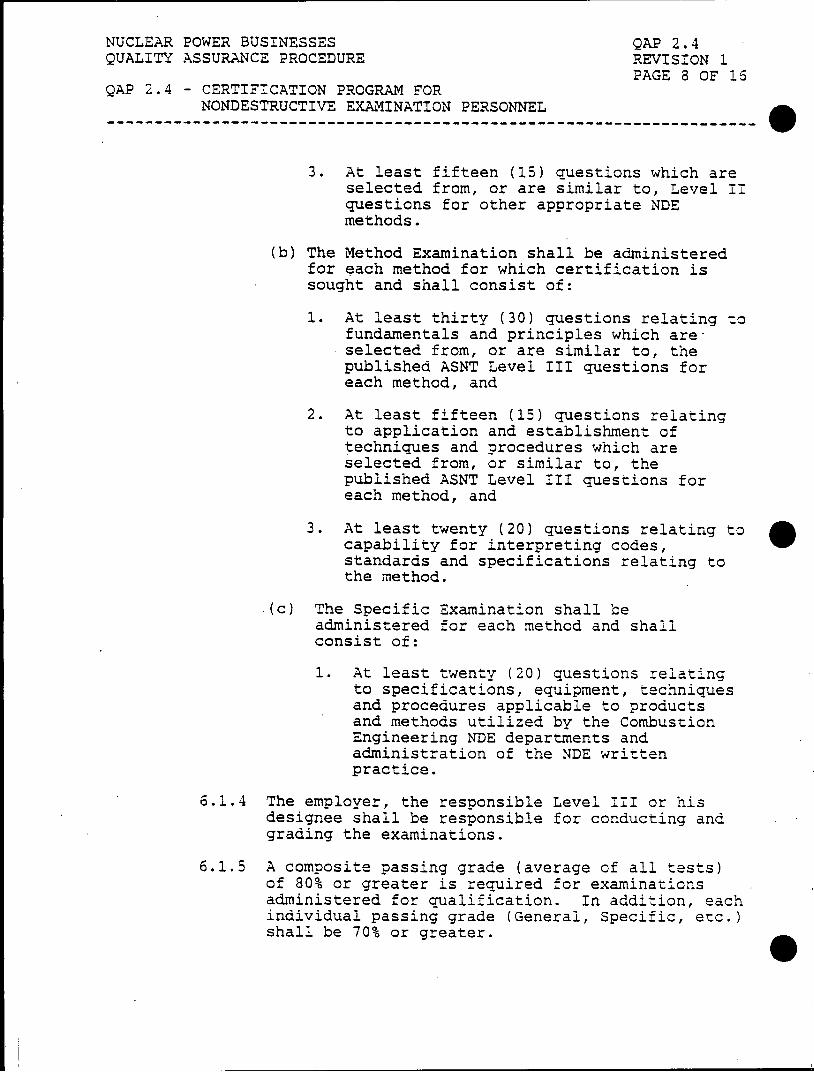
NUCLEAR POWER BUSINESSES QAP 2.4 QUALITY ASSURANCE PROCEDURE REVISION 1
PAGE 8 OF 16 QAP 2.4 - CERTIFICATION PROGRAM FOR
NONDESTRUCTIVE EXAMINATION PERSONNEL ~~~-------------- ---------------------------------
3. At least fifteen (15) questions which are selected from, or are similar to, Level II questions for other appropriate NDE methods.
(b) The Method Examination shall be administered for each method for which certification is sought and shall consist of:
1. At least thirty (30) questions relating to fundamentals and principles which areselected from, or are similar to, the published ASNT Level III questions for each method, and
2. At least fifteen (15) questions relating to application and establishment of techniques and procedures which are selected from, or similar to, the published ASNT Level III questions for each method, and
3. At least twenty (20) questions relating to capability for interpreting codes, standards and specifications relating to the method.
.(c) The Specific Examination shall be administered for each method and shall consist of:
1. At least twenty (20) questions relating to specifications, equipment, techniques and procedures applicable to products and methods utilized by the Combustion Engineering NDE departments and administration of the NDE written practice.
6.1.4 The employer, the responsible Level III or his designee shall be responsible for conducting and grading the examinations.
6.1.5 A composite passing grade (average of all tests) of 80% or greater is required for examinations administered for qualification. In addition, each individual passing grade (General, Specific, etc.) shall be 70% or greater.
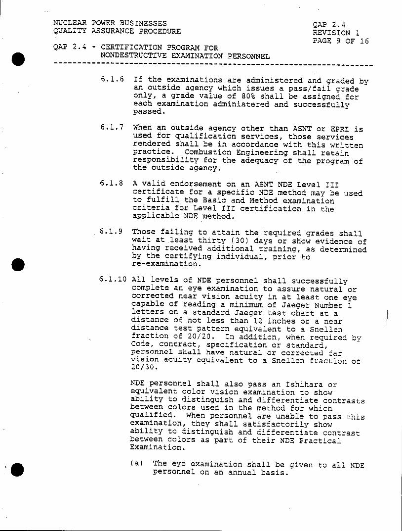
NUCLEAR POWER BUSINESSES QAP 2.4 QUALITY ASSURANCE PROCEDURE REVISION 1
PAGE 9 OF 16 QAP 2.4 - CERTIFICATION PROGRAM FOR
NONDESTRUCTIVE EXAMINATION PERSONNEL --------------------------------------------------------------------------
6.1.6 If the examinations are administered and graded by an outside agency which issues a pass/fail grade only, a grade value of 80% shall be assigned for each examination administered and successfully passed.
6.1.7 When an outside agency other than ASNT or EPRI is used for qualification services, those services rendered shall be in accordance with this written practice. Combustion Engineering shall retain responsibility for the adequacy of the program of the outside agency.
6.1.8 A valid endorsement on an ASNT NDE Level III certificate for a specific NDE method may be used to fulfill the Basic and Method examination criteria for Level III certification in the applicable NDE method.
6.1.9 Those failing to attain the required grades shall wait at.least thirty (30) days or show evidence of having received additional training, as determined by the certifying individual, prior to re-examination.
6.1.10 All levels of NDE personnel shall successfully complete an eye examination to assure natural or corrected near vision acuity in at least one eve capable of reading a minimum of Jaeger Number 1 letters on a standard Jaeger test chart at a distance of not less than 12 inches or a near distance test pattern equivalent to a Snellen fraction of 20/20. In addition, when required by Code, contract, specification or standard, personnel shall have natural or corrected far vision acuity equivalent to a Snellen fraction of 20/30.
NDE personnel shall also pass an Ishihara or equivalent color vision examination to show ability to distinguish and differentiate contrasts between colors used in the method for which qualified. When personnel are unable to pass this examination, they shall satisfactorily show ability to distinguish and differentiate contrast between colors as part of their NDE Practical Examination.
(a) The eye examination shall be given to all NDE personnel on an annual basis.
NUCLEAR POWER BUSINESSES QAP 2.4 QUALITY ASSURANCE PROCEDURE REVISION 1
PAGE 10 OF 16 QAP 2.4 - CERTIFICATION PROGRAM FOR
NONDESTRUCTIVE EXAMINATION PERSONNEL ~~-------------- ---------------------------------
(b) Eye examinations shall be performed by a Level III, his designate, or medical personnel.
(c) The results of the examination shall be recorded on the Eye Examination Record as shown on Exhibit 2.4-1 or equivalent.
7.0 CERTIFICATION
7.1 A Level III shall certify Level I and II personnel. Certification of Level III personnel shall be by the responsible department head. All certifications shall be documented on a Certification Record as shown on Exhibit 2.4-2.
7.2 The certification period for Levels I and II personnel shall be three (3) years. For Level III personnel, the certification period shall be:
(a) three (3) years for personnel performing work governed by ASME Code Section XI, or
(b) five (5) years for all other Level III Personnel.
7.3 Certification of all levels of NDE personnel shall be based on successful completion of the education, training and experience requirements of Paragraph 5.0 and the required examinations of Paragraph 6.0.
7.3.1 The maximum duration of interrupted service for each NDE method or technique shall be one (1) year. Where evidence of use of the method or technique can not be shown, the individual shall successfully complete the examinations deemed necessary by the responsible Level III or department head prior to reactivating the certification.
7.4 New employees having held valid NDE certifications with their former employer may be certified to their former NDE levels provided that:
7.4.1 The employee provides proof of prior certifications, or
7.4.2 The former employer provides documentaticn substantiating the training and experience qualification obtained by the employee. The qualifications shall meet the requirements of SNT-TC-1A (reference 2.2) and this written practice.
NUCLEAR POWER BUSINESSES QAP 2.4 QUALITY ASSURANCE PROCEDURE REVISION 1
PAGE 11 OF 16 QAP 2.4 - CERTIFICATION PROGRAM FOR
NONDESTRUCTIVE EXAMINATION PERSONNEL ---------------------------------------------------------------
NOTE: Every attempt shall be made to procure the documentation that substantiates the certification, however
a. When the former employer will not verify training and experience time, an individual's personal history may be acceptable documentation.
b. The employee's former training and experience may be verified by telephone. A record of telephone conversation shall be acceptable documentation of an individual's prior training and/or experience when documentation is otherwise unavailable.
7.4.3 The employee was working in the test method within six months of termination and is certified within six months after termination.
(a) When limits are in excess of those specified above, the employee shall receive additional training, as determined by the certifying individual, prior to certification.
7.4.4 The employee successfully completes the examination requirements, as applicable, of Paragraph 6.0.
7.5 Certification shall be revoked by the responsible Level III or department head by evidence of unsatisfactory performance or termination of employment. Individuals who are separated shall not be considered terminated provided they return to work within one year.
8.0 RECERTIFICATION
8.1 Levels I and II personnel shall be recertified at least every three (3) years by either evidence of continued satisfactory performance or re-examination based on the governing Code and contract requirements.
8.2 Level III personnel shall be recertified at least every:
(a) three (3) years for personnel performing work governed by ASME Code Section XI, or
(b) five (5) years for all other Level III personnel.
NUCLEAR POWER BUSINESSES QAP 2.4 QUALITY ASSURANCE PROCEDURE REVISION 1
PAGE 12 OF 16 QAP 2.4 - CERTIFICATION PROGRAM FOR
NONDESTRUCTIVE EXAMINATION PERSONNEL ---------------------------------------------------------------
8.2.1 Recertification shall be by either continued satisfactory performance or re-examination based on the governing Code and contract requirements. When a Level III is recertified by continued satisfactory performance, the recertification shall be based on documented evidence performing Level III duties such as NDE training, procedure development, certification of Level I's and Level II's, test development, etc.
9.0 RECORDS
9.1 The qualification records of the certified individual shall be maintained and shall include the following:
(a) Name of the certified individual.
(b) Level of certification and test method.
(c) Educational background and experience of the certified individual.
(d) Statement indicating satisfactory completion of training in accordance with this procedure.
(e) Results of the physical examination prescribed in Paragraph 6.1.10.
(f) Current examination copy(s) or evidence of successful completion of the examinations.
(g) Other suitable evidence of satisfactory qualifications when such qualifications are used in lieu of examinations.
(h) Composite grade(s) or suitable evidence of grades.
(i) Date of certification and/or recertification and the date of assignment to NDE.
(j) Signature of employer's designated representative.
9.2 Records shall be maintained by the responsible group or department and become quality records in accordance with QAP 17.1 when an individual has terminated or transferred from the department.
APPROVED: NDE Level IIt
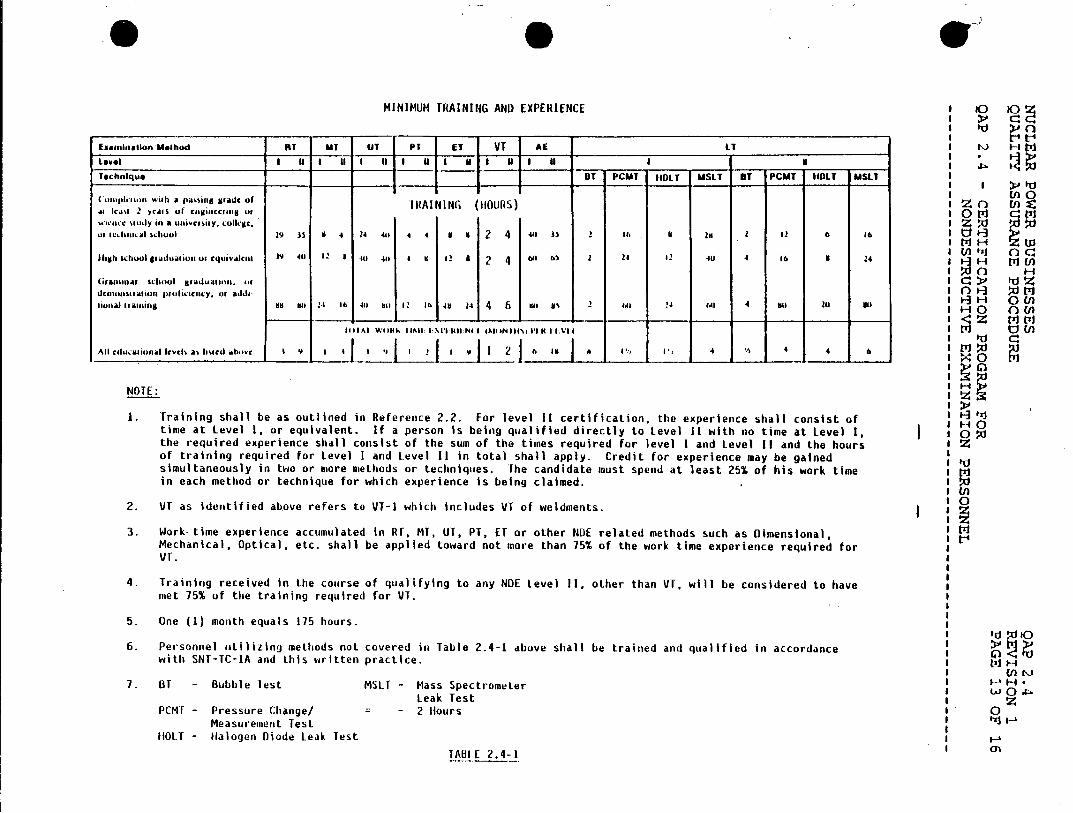
* MINIMUM TRAINING AND EXPERIENCE 10 O
Eneminallon Meihod RT MT UT PT ET VT AE LT H P1
Level I M I 11 1 i I U I N I a I I Technique UT PCMT IIDLT USLT OT PCMT HOLT MSLT
I1 11IIC11 -11 a I)% ig SFAICOfI Lonlennc~ w~ith a4 passing 14ade o TRAINING (HOURS) I EnO s Icat 2 ycars of clginctauig4 or 0th ws.wnce ludy in a unaivcrsiy, collec. zW in ichc alsi i school 29 is iI 4 24 411 4 4 9 8 2 4 44, Is 2 It, 14 21 2 42 6 16 I U
1I71H ZO high schooI graduaion ar cquivaleInt 19 40 42 8 40 411 4 It 12 a 2 4 6th 65 2 24 Q2 40 4 16 1 24 1 Un
Graminar school g#Aduatil. or I
dclonsgation proficancy. or addi- I
lional staining 141 sti 24 16 444 till 12 In 4H 24 4 Is a 2 t. 24 4d) 4 141 2U 80 1 H O 0 (
44 IAl Willis IINli::I til:WN4I 41IN4I\4 i sVIs I1:VI I - En
AI cducanalcycsasleted abowc 4 9 I 4 ' I [ J2j to lb a 4'. i 4 4 4 4 6 W
NOTE:
1. Training shall be as outlined in Reference 2.2. For level II certification, the experience shall consist of time at Level 1, or equivalent. If a person is being qualified directly to Level II with no time at Level I, 1 0 Pi the required experience shall consist of the sum of the times required for level I and Level II and the hours I z of training required for Level I and Level 11 in total shall apply. Credit for experience may be gained simultaneously in two or more methods or techniques. The candidate must spend at least 25% of his work time in each method or technique for which experience is being claimed.
I U)
2. VT as identified above refers to VT-I which includes VT of weldments.
3. Work. time experience accumulated in RT, MT, UT, PT, ET or other NDE related methods such as Dimensional, Mechanical, Optical, etc. shall be applied toward not more than 75% of the work time experience required for VT.
4. Training received in the course of qualifying to any NDE Level 11, other than VT. will be considered to have met 75% of the training required for VT.
5. One (1) month equals 175 hours.
6. Personnel utilizing methods not covered in Table 2.4-1 above shall be trained and qualified in accordance with SNT-TC-lA and this written practice.
7. BT - Bubble lest MSLT - Mass Spectrometer W Leak Test z
PCMT - Pressure Change/ - 2 Hours 0 Measurement Test
HOLT - Halogen Diode Leak Test
ABI K2.4-1) K
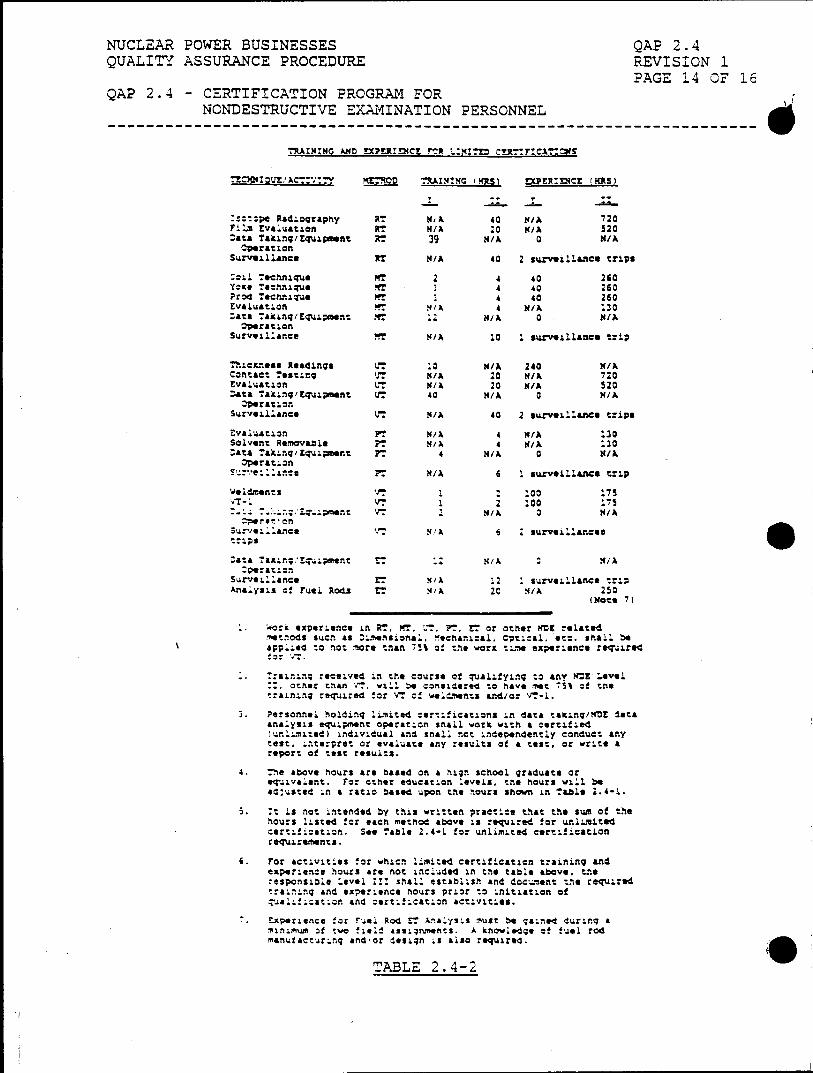
NUCLEAR POWER BUSINESSES QAP 2.4 QUALITY ASSURANCE PROCEDURE REVISION 1.
PAGE 14 OF 16 QAP 2.4 - CERTIFICATION PROGRAM FOR
NONDESTRUCTIVE EXAM4INATI ON PERSONNEL
?~I GA.ND EXPiu:Vct "ct L.2:M! TeAI
-Z~=P Radi.ographiy RT NJA 40 N/A 720 FIilm Evaluati.on N/ MA :0 M/A 520 .at& Taking/Equipment RT 39 N/ 0NA
Operation Surveillance RT N/A 40 2 survei~lla~nce trips
:Z11 Tehnl1ique 2 4 40 260 YOKO Technique Vr 4 40 260 Prod Techni~que n34 40 260
tvauatlon ?T N/A 4 N/A 1230 Aa .&Anq/Equiment Pf NA 0 MINA Operation
Survillance N? /A 1.0 .surveillance trip
Thic~nees Readi.ngs VT .0 N/A 240 N/X Czntact. Testing UT /MA z0 N/X 720 Evaluation VT N/A 20 N/A 520 :at& Taking/'Euiinnt UT 40 N/A a N/A
Operati.on Surveill.ance VT N/A 40 2 surveill.ance trip*
Zvalation PT N/A 4 N/A 130 solvent Removable ?T N/A 4 N/A 130 Zata Eakiq/quip?*rnt PT 4 N/A 0 N/A Opotaton
PT M/A 6 1 Surveillance trip
'Joldmonts V 1. 00 173 .1i.VT12 100 1"15
S VT N/A 0 N/A --pr *' on
Surveillance 4. !A 6 2surveillances
Zeta Taking;..qupet EN/A M/A :pe:at.n
Surveillance ET N/A 1.2 1surveillance trip Analysis of Fuel Rods ET N/1A 20 M/A 250
(Note 7)
Work experience in RT. %f. :7 PT, rT or other MZZ related me tnods- suon as i~nion&!, Mechanical, optical, etc. Snail be app...so !z not more thgan 7s% o! t.,e work t;.-e experience req.~iroe
7raininq received in the course of qualifying to any MME Le.vel :,other than V7, will beo cznsidered to have met 75% of the
training required for VT of woldiilentz and/or T.
3. Personnel holding limited certifications in data taking/ND! data analysis equLpimhnt operation snail w.orki with a certified un.,Imited) individual and snail not Independently conduct any
test, interpret or evaluate any resul.ts of a test, or write a report of test results.
4. The above hours are based on a high school graduate or *T41.va 1.ent. For other education levels. trio hours will be ed:ustsd in a ratio based upon thle hours shown in Table 1.4-1.
5. It is not intended by this written practice that the sum of the Ihours listed for each method above is required !or unlimited certification. See Table 2.4-1 for unlimited certification req'uireints.
6. For activities for which limited certification training and experience hours are not included in the table above. the% responsible Level :11 snail establish and dcc.ient the required traini.ng and experience hours prior to initiation of quali:tior. and certification activities.
Experience for Fuel Rod ET Analysis must be gained duringq a "inimum Of two fie!! assignments. A knowledge of fuel rod ,manufacturing and'or design is also required.
TABLE 2.4-2li
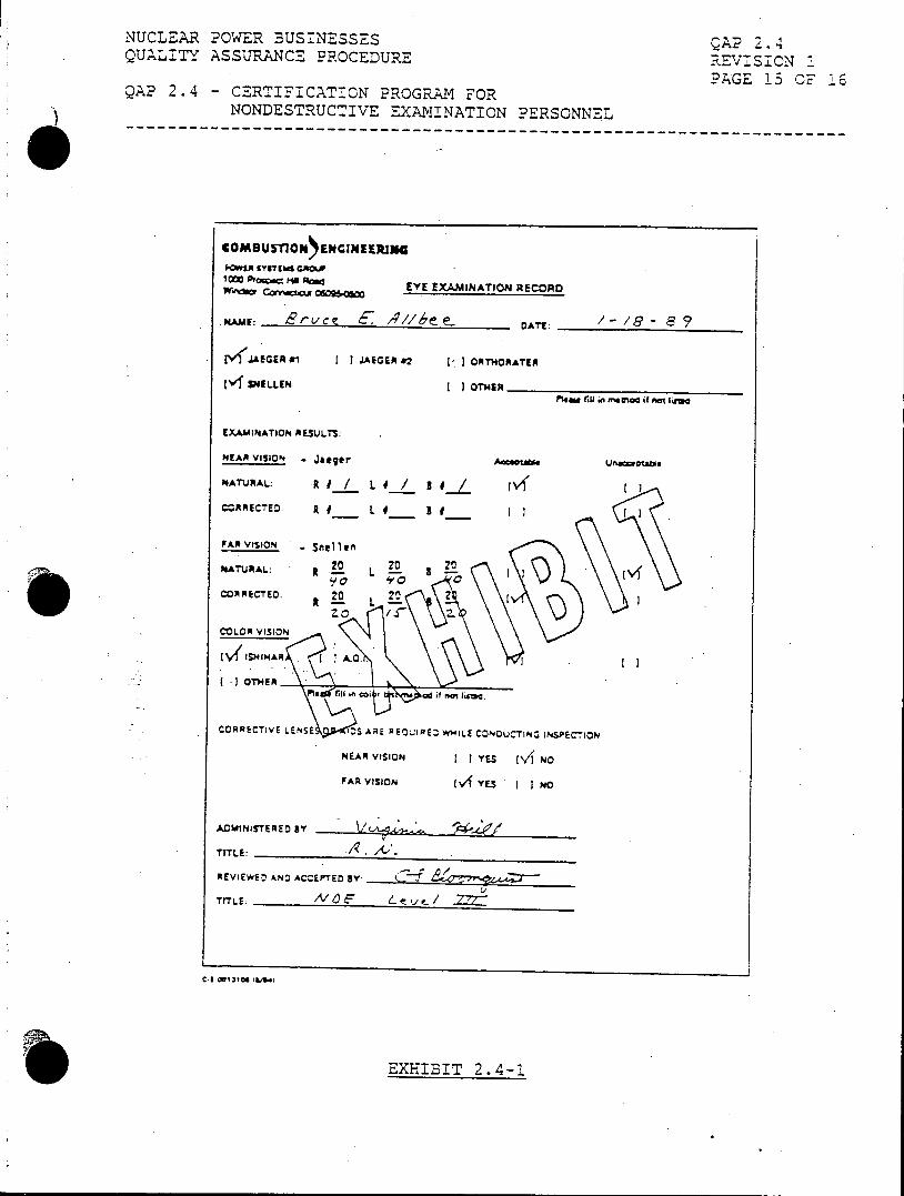
NUCLEAR POWER BUSINESSES QAP 2.4 QUA"LITY ASSURANCE PROCEDURE REVISION I
PAGE 13 CF 106 QAP 2.4 -CERTIFICATION PROGRAM FOR
NONDESTRUCTIVE EXAMINATION PERSONNEL
;low" lyWsTfu GXO.W 10M POGO MI Rftd
Wrx owos EY E EXMIINATION REOAD
NAE: srv'C c : DATE: 8
tV 4AEGEA J II.AEGER 82 ORTHORATER
[V SELLEN I OTHIR __________________
PI40 flU in fm. if maot IWWu
EXAMINATION RESUJLTS:
NEAR VISION - Jaeger U~uI
NATUPIALZ R1/ LI/ 3 .... rl CZRRECTED. R IF__ ___ __
FAR VISION Sre1it
NATURAL: R LO L 20 f
CORRCTE . - ' LL
COLOR VISION
OTHEO
CORRwETV LN IDA...~ t;IE WHL IOU N SpECr..CN
TITLE: ~,'
EXHIBIT 2.4-1