Embed Size (px)
Citation preview

Carlyle Paragon Series to BITZER CSW
Competitive Replacement Guideline
XR-0024-01 02/13
BITZER Screw Compressors CS High Temp Series
The intention of this document is to serve as general guidelines. The information contained is not intended to replace specific equipment and/or system manufacturer's information or guidelines. BITZER implies no liability for the information contained. It is BITZER's implicit
intention that nothing contained in this guide replaces any past, present or future warranty policy of BITZER and/or any other manufacturer's equipment
These guidelines are supplied as a recommended procedure for troubleshooting the CS screw compressor
These guidelines are not a replacement for information specific to that of the manufacturer or the manufacturer's system technical product information.
Each system may vary in design, usage and specifications. This document is intended for use specific to the compressor only and not intended to be a "catch all" for any and every possible
application of the compressor.
BITZER's intention is that only qualified and certified (where applicable) individuals specific to the refrigeration industry use the information contained and all standard refrigeration handling
and safety practices must be followed at all times.
BITZER's intention is that all electric work is performed by qualified and certified (where applicable) individuals and all standard electrical safety practices must be followed at all times.
WARNING This icon indicates instructions to avoid personal injury and material damage
CAUTION
This icon indicates instructions to avoid property damage and possible personal injury
HIGH VOLTAGE This icon indicates operations with a danger of electric shock

Table of Contents
Scope of Delivery BITZER CS and Carlyle Paragon 2
Capacity Comparison 3
Model Number Nomenclature 4
Overview 5
Capacity Control 6,7,8
Terminal Box Wiring and Module Types 9,10
Dimensions and Oil Types 11
Connection Comparisons and Weights 12
CFH and Motor Horsepower Comparison 13
Paragon Oil Separator and Components 14
CSW Oil Part Numbers 15
06T Paragon Assembly Drawings 16,17
CS Drawings 18,19
Competitive Replacement Request Form 21
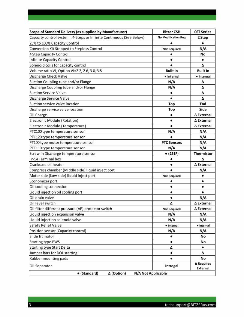
Scope of Standard Delivery (as supplied by Manufacturer) Bitzer CSH 06T Series
Capacity control system : 4-Steps or Infinite Continuous (See Below) No Modification Req 2 Step
25% to 100% Capacity Control ● ●
Conversion Kit Stepped to Stepless Control Not Required N/A
4 Step Capacity Control ● No
Infinite Capacity Control ● ●
Solenoid coils for capacity control ● Δ
Volume ratio Vi, Option Vi=2.2, 2.6, 3.0, 3.5 Built In Built In
Discharge Check Valve ● Internal ● Internal
Suction Coupling tube and/or Flange N/A Δ
Discharge Coupling tube and/or Flange N/A Δ
Suction Service Valve ● Δ
Discharge Service Valve ● Δ
Suction service valve location Top End
Discharge service valve location Top Side
Oil Charge ● Δ External
Electronic Module (Rotation) ● Δ External
Electronic Module (Temperature) ● Δ External
PTC100 type temperature sensor N/A N/A
PTC120 type temperature sensor ● N/A
PT100 type motor temperature sensor PTC Sensors N/A
PTC110 type temperature sensor N/A N/A
Screw in Discharge temperature sensor ● (251F) Thermistor
IP-54 Terminal box ● Δ
Crankcase oil heater ● Δ External
Compress chamber (Middle side) liquid inject port ● N/A
Motor side (Low side) liquid inject port Not Required ●
Economizer port ● ●
Oil cooling connection ● ●
Liquid injection oil cooling port ● ●
Oil drain valve ● N/A
Oil level switch Δ Δ External
Oil filter different pressure (ΔP) protector switch Not Required Δ External
Liquid injection expansion valve N/A N/A
Liquid injection solenoid valve N/A N/A
Safety Relief Valve ● Internal ● Internal
Position sensor (Capacity control) N/A N/A
Slide fit motor ● No
Starting type PWS ● No
Starting type Start Delta Δ ●
Jumper bars for DOL starting ● Δ
Rubber mounting pads ● No
Oil Separator IntregalΔ Requires
External
● (Standard) Δ (Option) N/A Not Applicable
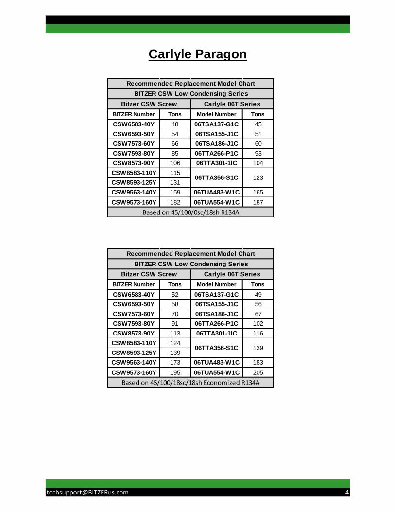
Carlyle Paragon
BITZER Number Tons Model Number Tons
CSW6583-40Y 48 06TSA137-G1C 45
CSW6593-50Y 54 06TSA155-J1C 51
CSW7573-60Y 66 06TSA186-J1C 60
CSW7593-80Y 85 06TTA266-P1C 93
CSW8573-90Y 106 06TTA301-1IC 104
CSW8583-110Y 115
CSW8593-125Y 131
CSW9563-140Y 159 06TUA483-W1C 165
CSW9573-160Y 182 06TUA554-W1C 187
06TTA356-S1C 123
Recommended Replacement Model Chart
Based on 45/100/0sc/18sh R134A
Bitzer CSW Screw Carlyle 06T Series
BITZER CSW Low Condensing Series
BITZER Number Tons Model Number Tons
CSW6583-40Y 52 06TSA137-G1C 49
CSW6593-50Y 58 06TSA155-J1C 56
CSW7573-60Y 70 06TSA186-J1C 67
CSW7593-80Y 91 06TTA266-P1C 102
CSW8573-90Y 113 06TTA301-1IC 116
CSW8583-110Y 124
CSW8593-125Y 139
CSW9563-140Y 173 06TUA483-W1C 183
CSW9573-160Y 195 06TUA554-W1C 205
06TTA356-S1C 139
Recommended Replacement Model Chart
BITZER CSW Low Condensing Series
Bitzer CSW Screw Carlyle 06T Series
Based on 45/100/18sc/18sh Economized R134A
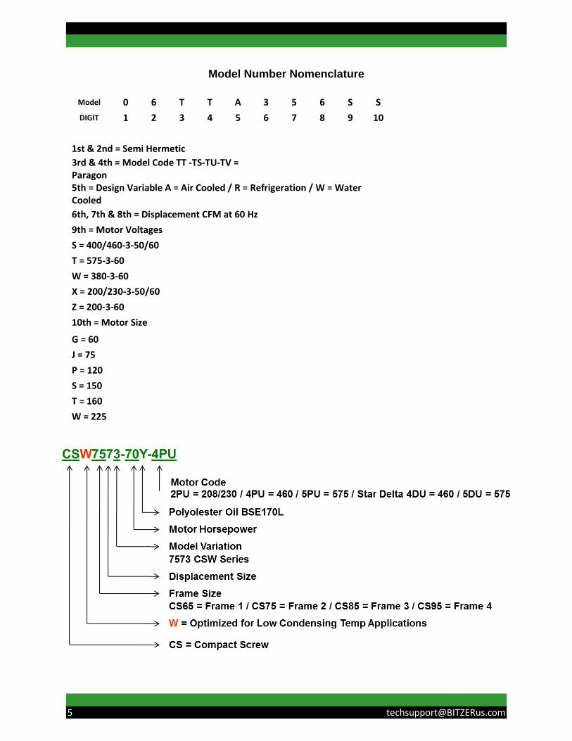
Model Number Nomenclature
Model 0 6 T T A 3 5 6 S S
DIGIT 1 2 3 4 5 6 7 8 9 10
1st & 2nd = Semi Hermetic
3rd & 4th = Model Code TT -TS-TU-TV = Paragon
5th = Design Variable A = Air Cooled / R = Refrigeration / W = Water Cooled
6th, 7th & 8th = Displacement CFM at 60 Hz
9th = Motor Voltages
S = 400/460-3-50/60
T = 575-3-60
W = 380-3-60
X = 200/230-3-50/60
Z = 200-3-60
10th = Motor Size
G = 60 J = 75 P = 120 S = 150 T = 160 W = 225
Overview
To aid in the conversion from a Carlyle Paragon Screw Compressor to a BITZER CSW Screw Compressor the following information has been assembled. For replacement compressor selection a capacity comparison of each compressor is given on page #3 and dimensional information is given on page #11. The suction and discharge connection sizes are different between the Carlyle and the BITZER CSW compressors. Size information is given on page #12. The Carlyle Paragon Compressors have the suction connection located on the end of the compressor. The discharge connection is located on the side of the compressor. The BITZER CSW compressors have the service valves located on the top of the compressor for the CS65, 75 and 85 series. The suction connection is located on the ends for the CSW9563-140Y and CSW9573-160Y. The suction and discharge isolation valves (if used) can be removed from the existing piping on the Carlyle compressor. The BITZER CS compressors are supplied with suction and discharge service valves and an internal discharge check valve. The weights of the compressors are similar and are listed on page #13. The control wiring for these compressors also has some differences. The Carlyle Paragon series has an optional Safety Control Module. This module provides safety control functionality for discharge temperature, oil level (external oil separator), reverse rotation and oil flow monitoring. The Carlyle has a thermal motor protector where the control circuit is wired through terminals S1 & S2. On the BITZER CSW compressors the control circuit is wired through terminals 11 & 14 and module power is connected to L & N. There is an additional connection on the BITZER CSW protection module at terminal 12. This can be used to indicate a general compressor failure. The optional safety module used on the Paragon should be removed. The BITZER electronic module provides oil temperature and motor winding temperature protection as well as phase rotation protection. The loading and unloading between the compressors is very similar. The Carlyle Paragon Series offers Infinite Capacity Control via two solenoids. The BITZER CSW Series offers Infinite Capacity Control or 4 Step Discreet Capacity Control via four solenoids provided on the compressor. Stepped Capacity control is not provided on the Paragon compressors. Either mode of capacity control can be achieved without any modification required when using the BITZER CSW compressors.

Capacity Control
For the BITZER CSW Compressor Infinite Capacity Control
Operation Solenoid 3 Solenoid 4
Start / Stop Energized De-energized
Loading De-energized Energized
Unloading Energized De-energized
Constant Load De-energized De-energized
For the BITZER CSW Compressor Stepped Control
Operation Solenoid 1 Solenoid 2 Solenoid 3 Solenoid 4
100% De-energized De-energized De-energized Energized
75% Energized De-energized De-energized De-energized
50% De-energized Energized De-energized De-energized
25% (Start) De-energized De-energized Energized De-energized
Mode Increase Capacity
Decrease Capacity
Partial Capacity*
Solenoid #1 Energized De-energized De-energized
Solenoid #2 Energized De-energized Energized
* Maintain capacity: Solenoid activation after proper slide valve position has been attained.

Bitzer Screw Compressors Frame 2 Shown
CR1 75%
CR2 50%
CR4 100% CR3
25%
Crankcase Heater
Oil Level Control (Option)
Oil Sight glass
Oil Drain Valve
Carlyle Paragon 06 Series Screw Compressors

To fully load the compressor, both solenoid #1 and #2 are energized. This allows high pressure oil to
enter the unloader piston chamber moving the slide valve providing more engagement under the screw
rotors. Both solenoids should remain energized to maintain the full load position.
To unload the compressor, both solenoids are de-energized. This exposes the unloader piston chamber
to suction pressure pulling the slide valve out from under the screw rotors reducing the amount of
compression being performed.
Part load is achieved by stopping the load or unload solenoids described above at an intermediate slide
valve position. Stopping the valve at an intermediate position is accomplished by de-energizing solenoid
#1 and energizing solenoid #2. When this takes place, both valves are closed and the piston cannot
move. Cycling of the solenoids may be required to maintain the position due to leak rates around the seal.

The last thing that needs to be checked is starting. In applications where reduced voltage starting is used
the Paragon will have a Star Delta starter which is different than the BITZER CS compressor, which
uses part winding starting for the CS65, 75 and 85 series. The CS95 series utilize Star Delta reduced
voltage starting. Full voltage or direct on line starting is the same for both compressors.
The overload relay and the contactors must be checked for proper sizing.
CS Terminal Box Wiring
06 Series Typical Terminal Box Wiring
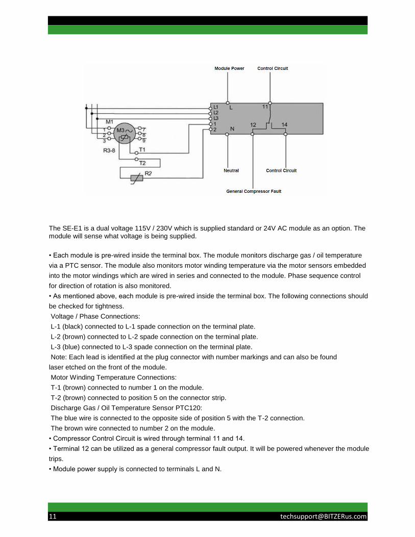
The SE-E1 is a dual voltage 115V / 230V which is supplied standard or 24V AC module as an option. The module will sense what voltage is being supplied.
• Each module is pre-wired inside the terminal box. The module monitors discharge gas / oil temperature
via a PTC sensor. The module also monitors motor winding temperature via the motor sensors embedded
into the motor windings which are wired in series and connected to the module. Phase sequence control
for direction of rotation is also monitored.
• As mentioned above, each module is pre-wired inside the terminal box. The following connections should
be checked for tightness.
Voltage / Phase Connections:
L-1 (black) connected to L-1 spade connection on the terminal plate.
L-2 (brown) connected to L-2 spade connection on the terminal plate.
L-3 (blue) connected to L-3 spade connection on the terminal plate.
Note: Each lead is identified at the plug connector with number markings and can also be found
laser etched on the front of the module.
Motor Winding Temperature Connections:
T-1 (brown) connected to number 1 on the module.
T-2 (brown) connected to position 5 on the connector strip.
Discharge Gas / Oil Temperature Sensor PTC120:
The blue wire is connected to the opposite side of position 5 with the T-2 connection.
The brown wire connected to number 2 on the module.
• Compressor Control Circuit is wired through terminal 11 and 14.
• Terminal 12 can be utilized as a general compressor fault output. It will be powered whenever the module
trips.
• Module power supply is connected to terminals L and N.

Dimensions / Oil
Carlyle Model Height Width Length
06TSA137 16 19 41
06TSA155 16 19 41
06TSA186 16 19 43
06TTA266 19 21 50
06TTA301 19 21 51
06TTA356 19 21 53
06TUA483 21 23 58
06TUA554 21 23 60
All dimensions without electrical box, service valves or oil separator (inches)
Carlyle Model Height Width Length
CSW6583-40Y 22 22 44
CSW6593-50Y 22 22 44
CSW7573-60Y 24 22 53
CSW7593-80Y 24 22 53
CSW8573-90Y 24 22 53
CSW8583-110Y 29 28 61
CSW8593-125Y 29 28 61
CSW9563-140Y 29 28 61
CSW9573-160Y 33 28 72
All dimensions with electrical box, integral oil separator and service valves (inches)
BITZER Oil and Refrigerant Types
Refrigerant Standard Factory
Oil
R134A Solest 170L
Carlyle Oil and Refrigerant Types
Refrigerant Required Oil
R134A Emkarate RL 220H
Plus
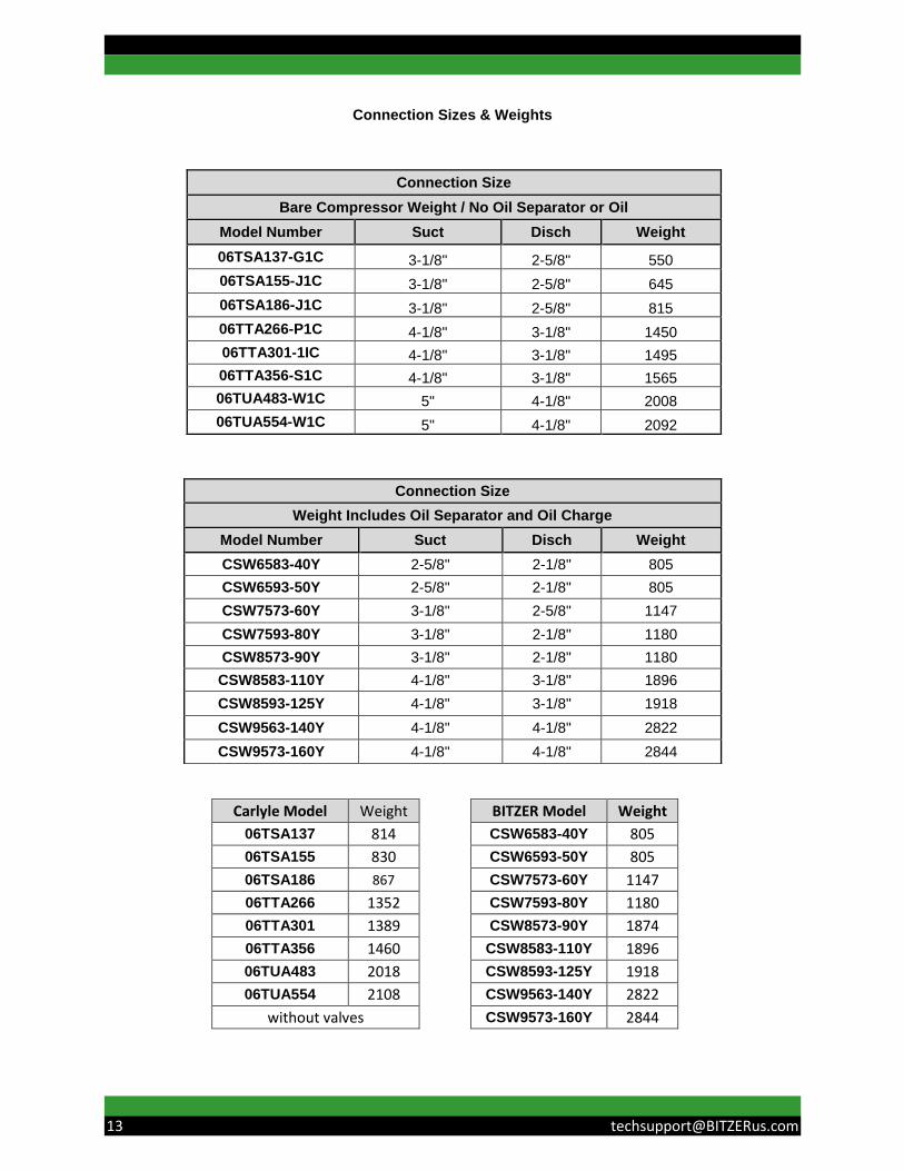
Connection Sizes & Weights
Carlyle Model Weight
BITZER Model Weight
06TSA137 814
CSW6583-40Y 805
06TSA155 830
CSW6593-50Y 805
06TSA186 867
CSW7573-60Y 1147
06TTA266 1352
CSW7593-80Y 1180
06TTA301 1389
CSW8573-90Y 1874
06TTA356 1460
CSW8583-110Y 1896
06TUA483 2018
CSW8593-125Y 1918
06TUA554 2108
CSW9563-140Y 2822
without valves
CSW9573-160Y 2844
Connection Size
Bare Compressor Weight / No Oil Separator or Oil
Model Number Suct Disch Weight
06TSA137-G1C 3-1/8" 2-5/8" 550
06TSA155-J1C 3-1/8" 2-5/8" 645
06TSA186-J1C 3-1/8" 2-5/8" 815
06TTA266-P1C 4-1/8" 3-1/8" 1450
06TTA301-1IC 4-1/8" 3-1/8" 1495
06TTA356-S1C 4-1/8" 3-1/8" 1565
06TUA483-W1C 5" 4-1/8" 2008
06TUA554-W1C 5" 4-1/8" 2092
Connection Size
Weight Includes Oil Separator and Oil Charge
Model Number Suct Disch Weight
CSW6583-40Y 2-5/8" 2-1/8" 805
CSW6593-50Y 2-5/8" 2-1/8" 805
CSW7573-60Y 3-1/8" 2-5/8" 1147
CSW7593-80Y 3-1/8" 2-1/8" 1180
CSW8573-90Y 3-1/8" 2-1/8" 1180
CSW8583-110Y 4-1/8" 3-1/8" 1896
CSW8593-125Y 4-1/8" 3-1/8" 1918
CSW9563-140Y 4-1/8" 4-1/8" 2822
CSW9573-160Y 4-1/8" 4-1/8" 2844

CFH and Motor Horsepower Rating
Carlyle 06T Bitzer CSW
Model Number Motor
HP Model Number Motor
HP
06TSA137-G1C 60 CSW6583-40Y 40
06TSA155-J1C 75 CSW6593-50Y 50
06TSA186-J1C 75 CSW7573-60Y 60
06TTA266-P1C 120 CSW7593-80Y 80
06TTA301-1IC 150 CSW8573-90Y 90
06TTA356-S1C 150 CSW8583-110Y 110
06TUA483-W1C 225 CSW8593-125Y 125
06TUA554-W1C 225 CSW9563-140Y 140
CSW9573-160Y 160
BITZER Number CFH 60Hz Model Number CFH 60Hz
CSW6583-40Y 8299 06TSA137-G1C 8220
CSW6593-50Y 9323 06TSA155-J1C 9300
CSW7573-60Y 10989 06TSA186-J1C 11160
CSW7593-80Y 14338 06TTA266-P1C 15960
CSW8573-90Y 17491 06TTA301-1IC 18060
CSW8583-110Y 20024
CSW8593-125Y 22602
CSW9563-140Y 26212 06TUA483-W1C 28980
CSW9573-160Y 29835 06TUA554-W1C 33240
06TTA356-S1C 21360
CFH Rating Model Chart
BITZER CSW Low Condensing Series
Bitzer CSW Screw Carlyle 06T Series
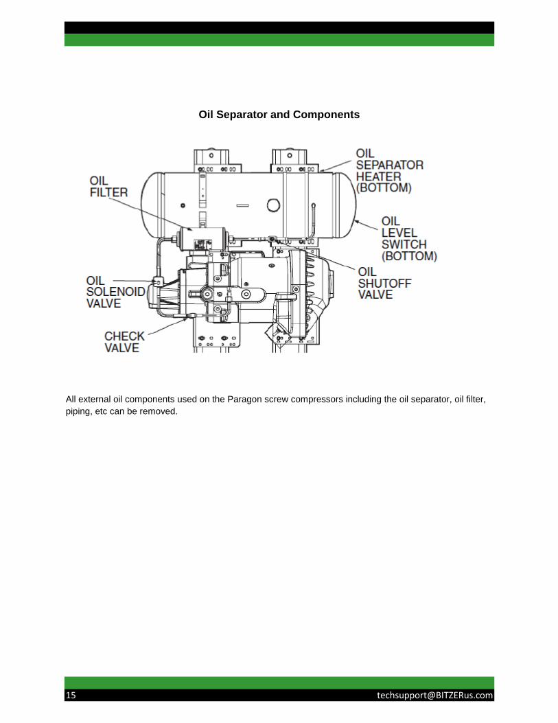
Oil Separator and Components
All external oil components used on the Paragon screw compressors including the oil separator, oil filter,
piping, etc can be removed.

BITZER Oils for CS Series
Model Refrigerant Oil
CSH R22 B320SH
R134a/R407C/R404A/R507A BSE170
CSW R22 B320SH
R134a BSE170L
B320SH Polyolester Oil
Unit of Measurement Part #
1 gallon 793-3320-01
5 gallon 793-3320-34
BSE 170 Polyolester Oil
Unit of Measurement Part #
1 gallon 793-1170-34
5 gallon 793-3170-34
BSE 170 L Polyolester Oil
Unit of Measurement Part #
1 liter 915118-06
5 liter 915118-01
10 liter 915118-02
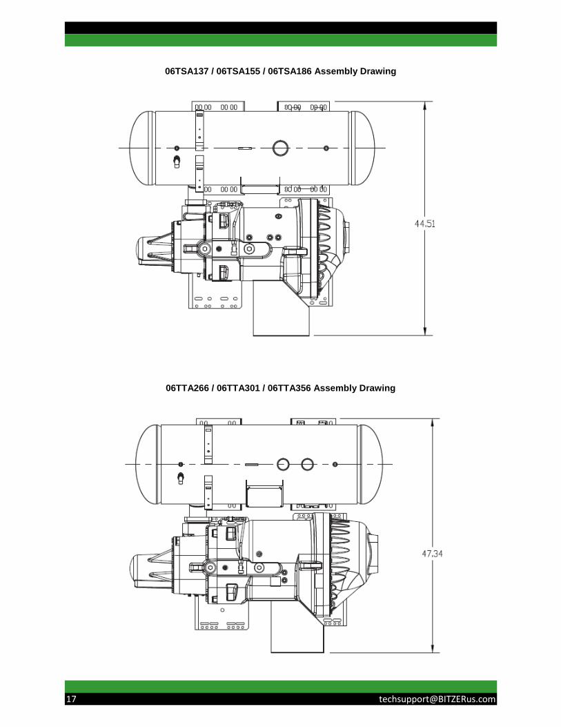
06TSA137 / 06TSA155 / 06TSA186 Assembly Drawing
06TTA266 / 06TTA301 / 06TTA356 Assembly Drawing

Notes
Please Note: The advice given herein and/or any conclusions made by BITZER US, Inc. represent BITZER US, Inc’s best advice and judgment under the circumstances, but such advice and/or conclusions made or results obtained shall be deemed used at your sole risk. For further assistance, please contact our application engineering department using the contact information on the back page of this booklet.

BITZER Competitive Replacement Inquiry
Date: ___________
Name
Company Name
Address
City, State, Zip
Phone
Cell Phone
Customer’s Name
Address
Brand of the compressor you are replacing: Compressor Model No.: Serial No.:
System Manufacturer (OEM) and Unit Model #:
Please specify single circuit or compressor is in parallel:
Type of refrigerant used: Tonnage requirement:
Operating condition: Evaporating:
Condensing:
Suction superheat:
Subcooling:
Voltage:
Reason for replacement:
How many compressors are you looking to replace?:
Please provide any additional comments: