Embed Size (px)
Citation preview
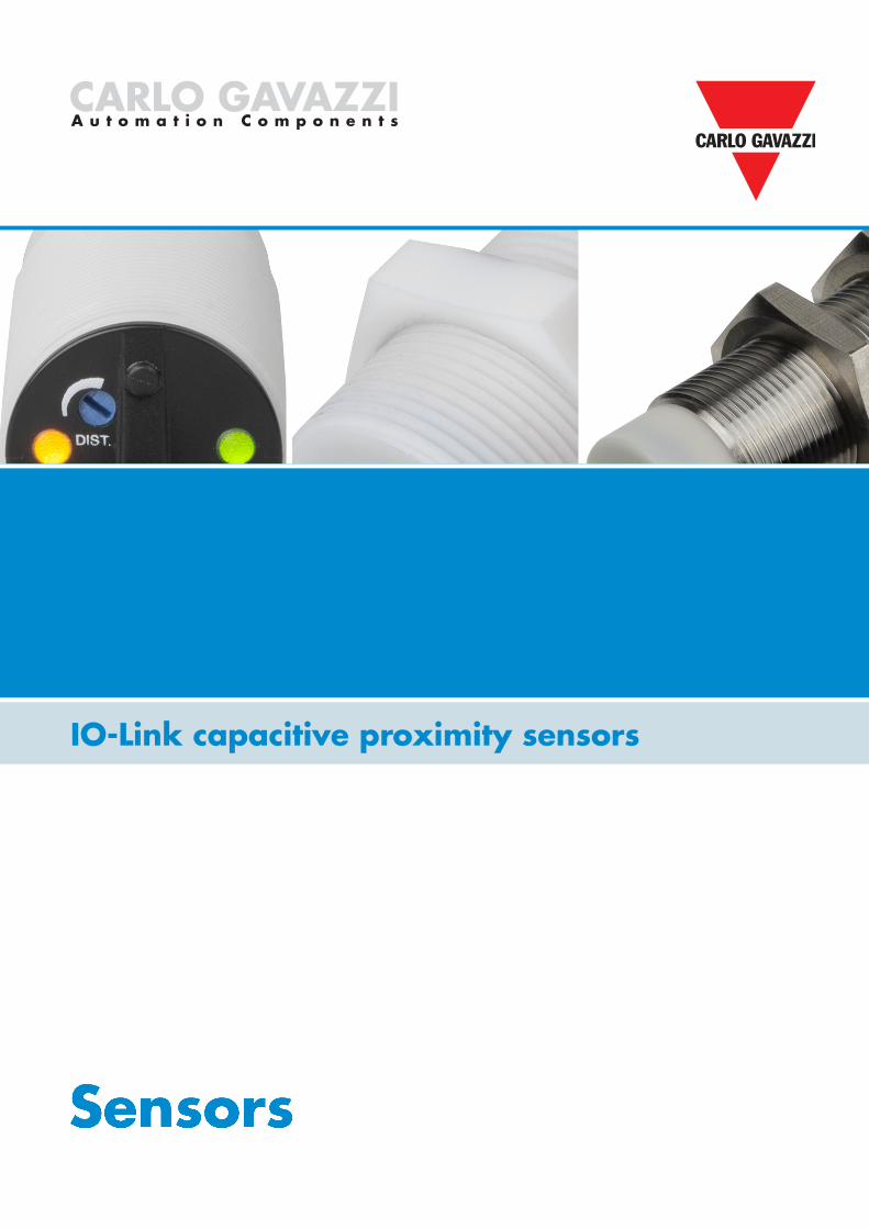
IO-Link capacitive proximity sensors

ADVANCEDDIAGNOSTICS
5
MULTI-FUNCTION
DEVICE
7
PREDICTIVEMAINTENANCE
8CONFIGURABLESENSORS
1
PLUG & PLAY
6
AUTOMATICPARAMETERSETTING
4
ADVANCEDDETECTION
2
REDUCEDINVENTORY
3
Carlo Gavazzi is proud to introduce this series of high- quality capacitive sensors to meet the demands of a new industrial era; an era that requires devices with enhanced capabilities and new ways of accessing, communicating and processing data. The Carlo Gavazzi IO-Link sensors combine their excellent features with the benefits of the IO-Link standard, which opens up the access to detailed information, advanced functionality and flexibility.The IO-Link system provides significant advantages including enhanced data availability and workability, remote configuration and automatic parameter settings, advanced diagnostics, simplified installation and easy sensor replacement.
Get ready for the era of Industry 4.0 and the Industrial Internet of Things!
Universal, smart and easy
CA18/30 seriesIO-Link capacitive proximity sensors
2
Data availability down to the field levelUsing IO-Link, the sensors can deliver their data directly into the control system very efficiently.
Device identificationEach IO-Link sensor has an IODD (IO Device Description), which describes the sensor, its capabilities and parameters, process data, diagnosis data and user interface configuration. Furthermore, each sensor is equipped with an internal ID.
Automatic parameter settingsInitial setup of a new sensor is smooth and easy using previously stored parameters. Once a sensor has been replaced, the IO-Link master simply transmits parameters stored from the old sensor.
ADVANCEDDIAGNOSTICS
5
MULTI-FUNCTION
DEVICE
7
PREDICTIVEMAINTENANCE
8CONFIGURABLESENSORS
1
PLUG & PLAY
6
AUTOMATICPARAMETERSETTING
4
ADVANCEDDETECTION
2
REDUCEDINVENTORY
3
CARLO GAVAZZI Automation Components. Specifications are subject to change without notice. Illustrations are for example only.

3
Universal, smart and easy
IO-LINK MASTERIO-LINK MASTER
IO-LINK SENSORS IO-LINK SENSORS
PLA
NT
CO
NTR
OL
DEV
ICE
1
L+
L-
C/Q IO-Link
SIO
43
2
What is IO-Link?IO-Link is a universal, open communication standard protocol that allows IO-Link-enabled devices to exchange, collect and analyse data and convert it into actionable information. IO-Link is recognised worldwide as an international standard (IEC 61131-9), and it is today considered as the “USB interface” for sensors and actuators in the industrial automation environment.
Plug and playWhen the IO-Link sensor is connected to an IO-Link port, the IO-Link master sends a wake-up request to the sensor, which automatically switches to IO-Link mode, and a point-to-point bidirectional communication automatically starts between the master and the sensor.
Operating modesThe IO-Link-capable sensor can operate in two different modes; SIO mode (standard I/O) or IO-Link mode.
• SIO mode: the sensor works as a traditional sensor, and pin 4 acts as an ordinary digital output. SIO mode ensures backwards compatibility with standard sensor systems.
• IO-Link mode: exchange of data between sensor and IO-Link master takes place, and pin 4 is used for the transmission of IO-Link-related data.
Pin Signal Remarks1 L+ 24 V
2 OUT Sensor dependent
3 L- Ground
4 C/Q Communication/ switching signal
Centralised configuration and data managementIO-Link enables fast configuration and dynamic change of the sensor parameters on the fly, which considerably reduces downtime in case of product changeover and increases flexibility and diversity of the installation.
Simplified installationAn IO-Link system requires just standard, unshielded 3-wire cables, and a standardised uniform interface
for sensors and actuators drastically reduce the complexity of the installation process. In addition, the automated parameter reassignment simplifies sensor replacement in case of defects and prevents incorrect settings. The IO-Link-enabled sensor acts as a standard sensor when installed in a non-IO-Link system, so the same sensor can be stocked for both standard I/O (SIO) applications and IO-Link applications.
Predictive maintenanceAdvanced and detailed diagnostics
mechanisms are one of the main features of the IO-Link sensors. Moreover, the sensors continuously deliver data on their condition and are able to detect defects at an early stage or predict when a machine needs repair or replacement of spare parts. Instead of unnecessary, frequent preventive maintenance, service is need-based, and the risk of machine stoppages is significantly reduced.
IO-Link
CARLO GAVAZZI Automation Components. Specifications are subject to change without notice. Illustrations are for example only.
4
CAPACITIVE SENSOR
Analogoutput
Fullyconfigurable
Selectableoutput/input
functions
Additional features - Logging functions
Hightemperature
Lowtemperature
Operationcycles
Operationhours
Switch pointmode
Logicfunctions Approval
Timerfunction
1
2
4
6
78
9
11
12
13
14
15
17 18 19
20
3
Outputs/inputs
Normally open (N.O.)
Normallyclosed (N.C.)
SSC1
SSC2
Dust(adjustablesetpoints)
Temperature(adjustablesetpoints)
Detectionfilter
5Predictive
maintenance
NPN, PNP,Push-Pull,External
input
Quality of runQuality of Teach
10
16
Externalinput
Powercycles
A
B
Q
24
AND
OR
XOR
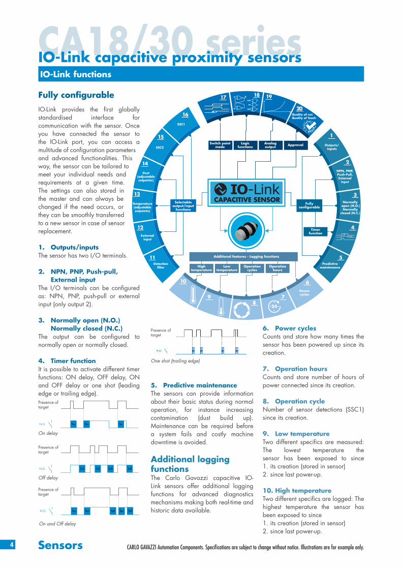
IO-Link functions
IO-Link provides the first globally standardised interface for communication with the sensor. Once you have connected the sensor to the IO-Link port, you can access a multitude of configuration parameters and advanced functionalities. This way, the sensor can be tailored to meet your individual needs and requirements at a given time. The settings can also stored in the master and can always be changed if the need occurs, or they can be smoothly transferred to a new sensor in case of sensor replacement.
1. Outputs/inputsThe sensor has two I/O terminals.
2. NPN, PNP, Push-pull, External inputThe I/O terminals can be configured as: NPN, PNP, push-pull or external input (only output 2).
3. Normally open (N.O.) Normally closed (N.C.)The output can be configured to normally open or normally closed.
4. Timer functionIt is possible to activate different timer functions: ON delay, OFF delay, ON and OFF delay or one shot (leading edge or trailing edge).
Fully configurable
5. Predictive maintenanceThe sensors can provide information about their basic status during normal operation, for instance increasing contamination (dust build up). Maintenance can be required before a system fails and costly machine downtime is avoided.
Additional logging functionsThe Carlo Gavazzi capacitive IO-Link sensors offer additional logging functions for advanced diagnostics mechanisms making both real-time and historic data available.
6. Power cyclesCounts and store how many times the sensor has been powered up since its creation.
7. Operation hoursCounts and store number of hours of power connected since its creation.
8. Operation cycleNumber of sensor detections (SSC1) since its creation.
9. Low temperatureTwo different specifics are measured: The lowest temperature the sensor has been exposed to since 1. its creation (stored in sensor)2. since last power-up.
10. High temperatureTwo different specifics are logged: The highest temperature the sensor has been exposed to since 1. its creation (stored in sensor) 2. since last power-up.
N.O. Ton Ton TonToff Toff
On and Off delay
Presence of target
Presence of target
N.O. Ton Ton Ton
On delay
Presence of target
Presence of target
N.O. Toff Toff Toff Toff
Off delay
Presence of target
One shot (trailing edge)
Presence of target
CA18/30 seriesIO-Link capacitive proximity sensors
CARLO GAVAZZI Automation Components. Specifications are subject to change without notice. Illustrations are for example only.

5
Selectable output/input functions
11. Detection filterIt is a stabilising filter that increases the immunity of the variation of the sensor’s measurements and media. The detection filter can be set to measure the average value of additional 1 to 255 mesurements.
12. External inputThe external input can be controlled by outputs from sensors or PLC’s.
13. Temperature alarmThe sensor can be configured to give an alarm if the temperature exceeds or drops below a preset value (Tmax or Tmin).
14. Dust alarmThe sensor can be configured to give an alarm if the contamination level exceeds a preset value of choice.
15. SSC1The Switching Signal Channel 1 (SSC1) output can be configured to the following four detection modes: Single-point mode, two-point mode, windows mode and adjustable hysteresis.Two individual setpoints and hysteresis can be set.
16. SSC2The Switching Signal Channel 2 (SSC2) output can be configured to the same modes as SSC1. Two individual setpoints and hysteresis can be set.
Switch point mode
17. Switch point modeSSC1 and SSC2 can be configured to single-point mode, two-point mode, windows mode, adjustable hysteresis.
Logic functions
18. Logic functionsIn the logic function block the selected signals from the input selector can be added a logic function directly without using a PLC – making decentral decisions possible.The logic functions available are: AND, OR, XOR and Gated SR-FF.
Sensor
Sensing distanceON OFF
SP1
Hysteresis
Single point mode
Sensor
Sensing distanceON OFF
SP2
Hysteresis
SP1
Two point mode
Sensor
Sensing distance
SP2
Hyst
OFF OFFON
SP1
Hyst
window
Windows mode
AN
IO-Link functions
Analogue output
19. Analogue output16 bit Analogue Output by IO-Link representing the Dielectric value measured by the sensor.
Approval
20. Quality of runThe quality of run value informs about the actual sensing performance compared to the set-points of the sensor, the higher the value the better quality of detection.
20. Quality of teachThe quality if teach value informs about how well the actually teach procedure was done, meaning the margin between the actual setpoints and the environmental influence of the sensor.
Protection
AND
OR
XOR
Gated SR-FF
4th Generation TRIPLESHIELDTM technology
IP69K
CARLO GAVAZZI Automation Components. Specifications are subject to change without notice. Illustrations are for example only.

6
CA18CAF..IO Flush
CA30CAF..IO Flush
CA18CAN..IO Non-Flush
CA30CAN..IO Non-Flush
Features and functions
All versions are avaliable as cable or M12 plug versions.
All versions are avaliable as cable or M12 plug versions.
120°C on sensing face
120°C on sensing face
30% glass reinforced PBT housing
30% glass reinforced PBT housing
CA18/30CA seriesIO-Link sensors in PBT housing
Flush
Flush
Non-flush
Non-flush
For flexibility and compatibility, the new sensors, whether flush or non-flush, share the same length.
M30 x 1.5 x 59.5
61
LED
86
86
M18 x 1.0 x 55
70
15
LED
86
M18 x 1.0 x 47
70
8 15
LED
M30 x 1.5 x 45.514.5
61
LED
86
Interchangeable housing length
M12 plug
M12 plug
Cable
Cable
Multiturn sensitivity adjustment for SCC1 only
Multiturn sensitivity adjustment for SCC1 only
Back part of the sensor
Back part of the sensor
Yellow LED• Output• Short circuit• Timer
Yellow LED• Output• Short circuit• Timer
Green LED• Power • Stability• IO-Link
communication
Green LED• Power • Stability• IO-Link
communication
CARLO GAVAZZI Automation Components. Specifications are subject to change without notice. Illustrations are for example only.

7
The Capacitive CA18/30CA IO-Link Family
M18 / M30 DC IO-Link 4TH Generation TRIPLESHIELDTM
M18 M30
Connection Flush Non-Flush Flush Non-Flush
Cable CA18CAF08BPA2IO CA18CAN12BPA2IO CA30CAF16BPA2IO CA30CAN25BPA2IO
Plug CA18CAF08BPM1IO CA18CAN12BPM1IO CA30CAF16BPM1IO CA30CAN25BPM1IO
Sensing distance 0 - 8 mm 0 - 12 mm 0 - 16 mm 0 - 25 mmAdjustable distance 2 - 10 mm 3 - 15 mm 2 - 20 mm 4 - 30 mm
IO-Link Transmission type: COM2 (38.4 k Baud), Revision: 1.1, SDCI standard: IEC 61131-9, Profiles: Smart sensor (Process Data Variable; Device Identification), SIO mode: Yes, Required master port type: A, Min. process cycle time [ms]: 5
Selectable function output 1 NPN, PNP or Push-PullSelectable function output 2 NPN, PNP, Push-Pull, External input or External teach
Diagnostic Operation hours, Power cycles, Detection cyclesmax. and min. Temperatures, Short-circuit, maintenaince, No of Parameter change.
Logic functions AND, OR, X-OR, Gated SR-FFTimer functions ON Delay. OFF delay, ON+OFF delay and One shotSensitivity control Trimmer input, Teach by wire or by IO-LinkRated operational voltage (Ue) 10 to 40 V DC (ripple included)No load supply current (Io) ≤ 20 mAMinimum operational current (Im) ≤ 0.5 mAOff-State current (Ir) ≤ 100 μAVoltage drop, digital (Ud) ≤ 1.0 V DC @ 200 mA DCCapacitive load 100 nF @ 200 mAFrequency of operating cycles (f) 50 HzResponse time tON or tOFF 10 msPower on delay (tv) 300 ms Hysteresis (adjustable) 6% 15% 7% 10%
Led indicationsYellow LED steady: Output ON and signal stability.
Yellow LED flashing: Output short-circuit, timer indication and teach. Green LED steady: Power ON and signal stability.
Green LED flashing: IO-Link mode.Sensor protection Shortcircuit (A), reverse polarity (B) and transients (C)Electrostatic discharge Contact discharge: > 40 kV. Air discharge: > 40 kV (IEC 61000-4-2)Electrical fast transients/burst ±4kV/5kHz (IEC 61000-4-4; EN 60947-1)Surge Power-supply: > 2kV (with 500 Ω). Sensor output: > 2kV (with 500 Ω) (IEC 61000-4-5)Wire conducted disturbances > 20 Vrms (IEC 61000-4-6)Power - frequency magnetic fields Continous: > 60 A/m, 75.9 µ tesla. Short-time: > 600 A/m, 759 µ tesla (IEC 61000-4-8)Radiated RF electromagnetic fields > 20 V/m (IEC 61000-4-3)Vibration 10 to 150 Hz, 1 mm/15G in X,Y and Z direction (EN 60068-2-6)Shock 30G /11 mS. 3 positive and 3 negative in X,Y and Z direction (EN 60068-2-27)Drop test 2 times from 1m, 100 times from 0,5m (EN 60068-2-31)Degree of protection IP 67, IP 68, IP 69K (EN 60529; EN 60947-1; DIN 40050-9)NEMA type 1, 2, 4, 4X, 5, 6, 6P, 12 (NEMA 250)Ambient temperature Operating: -30 to +85°C (-22 to +185°F). Storage: -40 to +85°C (-40 to +185°F ) Max. temperature on sensing face 120°C (248°F )CE marking According to EN 60947-5-2Approvals cULus (UL508), ECOLABOvervoltage category III (IEC60664; EN 60947-1)Pollution degree 3(IEC60664/60664A; EN 60947-1)MTTFd 114.6 years @ 40°C (104°F ) 98.3 years @ 40°C (104°F )Material Body: PBT grey, 30% glass reinforced. Trimmer shaft: Nylon, blue. Backpart: Grilamid TR55, black.Tightening torque ≤ 2.6 Nm ≤ 7.5 NmCable PCV, grey, 2 m, 4 x 0.34 mm2, Ø=5.2 mm, Oil proofConnector M12, 4-pinDimensions Cable and Plug: M18 x 70 mm Cable and Plug: M30 x 61 mmWeight incl. packaging Cable version ≤ 150 g, Plug version ≤ 75 g Cable version ≤ 190 g, Plug version ≤ 106 g
Accessories, additional Connectors: CONB14NF-...W -series. Mounting brackets: AMB18-A... and AMB18-S...
Connectors: CONB14NF-...W -series. Mounting brackets: AMB30-A... and AMB30-S...
IP69KCARLO GAVAZZI Automation Components. Specifications are subject to change without notice. Illustrations are for example only.
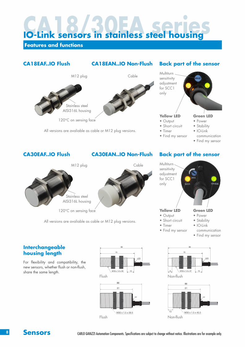
CA18EAF..IO Flush
CA30EAF..IO Flush
CA18EAN..IO Non-Flush
CA30EAN..IO Non-Flush
Features and functions
All versions are avaliable as cable or M12 plug versions.
All versions are avaliable as cable or M12 plug versions.
M12 plug
M12 plug
Cable
Cable
120°C on sensing face
120°C on sensing face
Stainless steel AISI316L housing
Stainless steel AISI316L housing
Flush
Flush
Non-flush
Non-flush
For flexibility and compatibility, the new sensors, whether flush or non-flush, share the same length.
M30 x 1.5 x 59.5
61
LED
86
86
M18 x 1.0 x 55
70
15
LED
86
M18 x 1.0 x 47
70
8 15
LED
M30 x 1.5 x 45.513
61
LED
86
Interchangeable housing length
8
CA18/30EA seriesIO-Link sensors in stainless steel housing
Multiturn sensitivity adjustment for SCC1 only
Multiturn sensitivity adjustment for SCC1 only
Back part of the sensor
Back part of the sensor
Yellow LED• Output• Short circuit• Timer• Find my sensor
Yellow LED• Output• Short circuit• Timer• Find my sensor
Green LED• Power • Stability• IO-Link
communication• Find my sensor
Green LED• Power • Stability• IO-Link
communication• Find my sensor
CARLO GAVAZZI Automation Components. Specifications are subject to change without notice. Illustrations are for example only.

9
The Capacitive CA18/30EA IO-Link Family
M18 / M30 DC IO-Link 4TH Generation TRIPLESHIELDTM
M18 M30
Connection Flush Non-Flush Flush Non-Flush
Cable CA18EAF08BPA2IO CA18EAN12BPA2IO CA30EAF16BPA2IO CA30EAN25BPA2IO
Plug CA18EAF08BPM1IO CA18EAN12BPM1IO CA30EAF16BPM1IO CA30EAN25BPM1IO
Sensing distance 0 - 8 mm 0 - 12 mm 0 - 16 mm 0 - 25 mmAdjustable distance 2 - 10 mm 3 - 15 mm 2 - 20 mm 4 - 30 mm
IO-Link Transmission type: COM2 (38.4 k Baud), Revision: 1.1, SDCI standard: IEC 61131-9, Profiles: Smart sensor (Process Data Variable; Device Identification), SIO mode: Yes, Required master port type: A, Min. process cycle time [ms]: 5
Selectable function output 1 NPN, PNP or Push-PullSelectable function output 2 NPN, PNP, Push-Pull, External input or External teach
Diagnostic Operation hours, Power cycles, Detection cyclesmax. and min. Temperatures, Short-circuit, maintenaince, No of Parameter change.
Logic functions AND, OR, X-OR, Gated SR-FFTimer functions ON Delay. OFF delay, ON+OFF delay and One shotSensitivity control Trimmer input, Teach by wire or by IO-LinkRated operational voltage (Ue) 10 to 40 V DC (ripple included)No load supply current (Io) ≤ 20 mAMinimum operational current (Im) ≤ 0.5 mAOff-State current (Ir) ≤ 100 μAVoltage drop, digital (Ud) ≤ 1.0 V DC @ 200 mA DCCapacitive load 100 nF @ 200 mAFrequency of operating cycles (f) 50 HzResponse time tON or tOFF 10 msPower on delay (tv) 300 ms Hysteresis (adjustable) 14% 15% 8% 10%
Led indications
Yellow LED steady: Output ON and signal stability. Yellow LED flashing: Output short-circuit, timer indication and teach.
Green LED steady: Power ON and signal stability. Green LED flashing: IO-Link mode.
Green and Yellow LEDs flashing: Find my sensor.Sensor protection Shortcircuit (A), reverse polarity (B) and transients (C)Electrostatic discharge Contact discharge: > 40 kV. Air discharge: > 40 kV (IEC 61000-4-2)Electrical fast transients/burst ±4kV/5kHz (IEC 61000-4-4; EN 60947-1)Surge Power-supply: > 2kV (with 500 Ω). Sensor output: > 2kV (with 500 Ω) (IEC 61000-4-5)Wire conducted disturbances > 20 Vrms (IEC 61000-4-6)Power - frequency magnetic fields Continous: > 60 A/m, 75.9 µ tesla. Short-time: > 600 A/m, 759 µ tesla (IEC 61000-4-8)Radiated RF electromagnetic fields > 20 V/m (IEC 61000-4-3)Vibration 10 to 150 Hz, 1 mm/15G in X,Y and Z direction (EN 60068-2-6)Shock 30G /11 mS. 3 positive and 3 negative in X,Y and Z direction (EN 60068-2-27)Drop test 2 times from 1m, 100 times from 0,5m (EN 60068-2-31)Degree of protection IP 67, IP 68, IP 69K (EN 60529; EN 60947-1; DIN 40050-9)NEMA type 1, 2, 4, 4X, 5, 6, 6P, 12 (NEMA 250)Ambient temperature Operating: -30 to +85°C (-22 to +185°F). Storage: -40 to +85°C (-40 to +185°F ) Max. temperature on sensing face 120°C (248°F )CE marking According to EN 60947-5-2Approvals cULus (UL508), ECOLABOvervoltage category III (IEC60664; EN 60947-1)Pollution degree 3(IEC60664/60664A; EN 60947-1)MTTFd 114.6 years @ 40°C (104°F ) 98.3 years @ 40°C (104°F )
Material Body: Stainless steel AISI316L. Front: PBT white, 30% glass reinforced. Trimmer shaft: Nylon, blue. Backpart: Grilamid TR55, black.
Tightening torque ≤ 25 Nm ≤ 30 NmCable PCV, grey, 2 m, 4 x 0.34 mm2, Ø=5.2 mm, Oil proofConnector M12, 4-pinDimensions Cable and Plug: M18 x 70 mm Cable and Plug: M30 x 61 mmWeight incl. packaging Cable version ≤ 170 g, Plug version ≤ 95 g Cable version ≤ 250 g, Plug version ≤ 175 g
Accessories, additional Connectors: CONB14NF-...W -series. Mounting brackets: AMB18-A... and AMB18-S...
Connectors: CONB14NF-...W -series. Mounting brackets: AMB30-A... and AMB30-S...
IP69KCARLO GAVAZZI Automation Components. Specifications are subject to change without notice. Illustrations are for example only.

10
Multiturn sensitivity adjustment for SCC1 only
Multiturn sensitivity adjustment for SCC1 only
CA18FAF..IO Flush
CA30FAF..IO Flush
CA18FAN..IO Non-Flush
CA30FAN..IO Non-Flush
Features and functions
Back part of the sensor
Back part of the sensor
Yellow LED• Output• Short circuit• Timer• Find my sensor
Yellow LED• Output• Short circuit• Timer• Find my sensor
Green LED• Power • Stability• IO-Link
communication• Find my sensor
Green LED• Power • Stability• IO-Link
communication• Find my sensor
All versions are avaliable as cable or M12 plug versions.
All versions are avaliable as cable or M12 plug versions.
120°C on sensing face
120°C on sensing face
PTFE housing
PTFE housing
CA18/30FA seriesIO-Link sensors in PTFE housing
Flush
Flush
Non-flush
Non-flush
For flexibility and compatibility, the new sensors, whether flush or non-flush, share the same length.
M30 x 1.5 x 59.5
61
LED
86
86
M18 x 1.0 x 55
70
15
LED
86
M18 x 1.0 x 47
70
8 15
LED
M30 x 1.5 x 45.513
61
LED
86
Interchangeable housing length
M12 plug
M12 plug
Cable
Cable
CARLO GAVAZZI Automation Components. Specifications are subject to change without notice. Illustrations are for example only.

ADVANCEDDIAGNOSTICS
5
MULTI-FUNCTION
DEVICE
7
PREDICTIVEMAINTENANCE
8CONFIGURABLESENSORS
1
PLUG & PLAY
6
AUTOMATICPARAMETERSETTING
4
ADVANCEDDETECTION
2
REDUCEDINVENTORY
3
11
The Capacitive CA18/30FA IO-Link Family
M18 / M30 DC IO-Link 4TH Generation TRIPLESHIELDTM
M18 M30
Connection Flush Non-Flush Flush Non-Flush
Cable CA18FAF08BPA2IO CA18FAN12BPA2IO CA30FAF16BPA2IO CA30FAN25BPA2IO
Plug CA18FAF08BPM1IO CA18FAN12BPM1IO CA30FAF16BPM1IO CA30FAN25BPM1IO
Sensing distance 0 - 8 mm 0 - 12 mm 0 - 16 mm 0 - 25 mmAdjustable distance 2 - 10 mm 3 - 15 mm 2 - 20 mm 4 - 30 mm
IO-Link Transmission type: COM2 (38.4 k Baud), Revision: 1.1, SDCI standard: IEC 61131-9, Profiles: Smart sensor (Process Data Variable; Device Identification), SIO mode: Yes, Required master port type: A, Min. process cycle time [ms]: 5
Selectable function output 1 NPN, PNP or Push-PullSelectable function output 2 NPN, PNP, Push-Pull, External input or External teach
Diagnostic Operation hours, Power cycles, Detection cyclesmax. and min. Temperatures, Short-circuit, maintenaince, No of Parameter change.
Logic functions AND, OR, X-OR, Gated SR-FFTimer functions ON Delay. OFF delay, ON+OFF delay and One shotSensitivity control Trimmer input, Teach by wire or by IO-LinkRated operational voltage (Ue) 10 to 40 V DC (ripple included)No load supply current (Io) ≤ 20 mAMinimum operational current (Im) ≤ 0.5 mAOff-State current (Ir) ≤ 100 μAVoltage drop, digital (Ud) ≤ 1.0 V DC @ 200 mA DCCapacitive load 100 nF @ 200 mAFrequency of operating cycles (f) 50 HzResponse time tON or tOFF 10 msPower on delay (tv) 300 ms Hysteresis (adjustable) 4% 15% 5% 10%
Led indications
Yellow LED steady: Output ON and signal stability. Yellow LED flashing: Output short-circuit, timer indication and teach.
Green LED steady: Power ON and signal stability. Green LED flashing: IO-Link mode.
Green and Yellow LEDs flashing: Find my sensor.Sensor protection Shortcircuit (A), reverse polarity (B) and transients (C)Electrostatic discharge Contact discharge: > 40 kV. Air discharge: > 40 kV (IEC 61000-4-2)Electrical fast transients/burst ±4kV/5kHz (IEC 61000-4-4; EN 60947-1)Surge Power-supply: > 2kV (with 500 Ω). Sensor output: > 2kV (with 500 Ω) (IEC 61000-4-5)Wire conducted disturbances > 20 Vrms (IEC 61000-4-6)Power - frequency magnetic fields Continous: > 60 A/m, 75.9 µ tesla. Short-time: > 600 A/m, 759 µ tesla (IEC 61000-4-8)Radiated RF electromagnetic fields > 20 V/m (IEC 61000-4-3)Vibration 10 to 150 Hz, 1 mm/15G in X,Y and Z direction (EN 60068-2-6)Shock 30G /11 mS. 3 positive and 3 negative in X,Y and Z direction (EN 60068-2-27)Drop test 2 times from 1m, 100 times from 0,5m (EN 60068-2-31)Degree of protection IP 67, IP 68, IP 69K (EN 60529; EN 60947-1; DIN 40050-9)NEMA type 1, 2, 4, 4X, 5, 6, 6P, 12 (NEMA 250)Ambient temperature Operating: -30 to +85°C (-22 to +185°F). Storage: -40 to +85°C (-40 to +185°F ) Max. temperature on sensing face 120°C (248°F )CE marking According to EN 60947-5-2Approvals cULus (UL508), ECOLABOvervoltage category III (IEC60664; EN 60947-1)Pollution degree 3(IEC60664/60664A; EN 60947-1)MTTFd 114.6 years @ 40°C (104°F ) 98.3 years @ 40°C (104°F )Material Body: PTFE. Trimmer shaft: Nylon, blue. Backpart: Grilamid TR55, black.Tightening torque ≤ 1 Nm ≤ 2 NmCable PCV, grey, 2 m, 4 x 0.34 mm2, Ø=5.2 mm, Oil proofConnector M12, 4-pinDimensions Cable and Plug: M18 x 70 mm Cable and Plug: M30 x 61 mmWeight incl. packaging Cable version ≤ 150 g, Plug version ≤ 75 g Cable version ≤ 190 g, Plug version ≤ 106 g
Accessories, additional Connectors: CONB14NF-...W -series. Mounting brackets: AMB18-A... and AMB18-S...
Connectors: CONB14NF-...W -series. Mounting brackets: AMB30-A... and AMB30-S...
IP69KCARLO GAVAZZI Automation Components. Specifications are subject to change without notice. Illustrations are for example only.

BRO
Cap
aciti
ve IO
-Link
EN
G re
v. 0
2 - 0
2.20
20Sp
ecifi
catio
ns a
re s
ubje
ct to
cha
nge
with
out n
otic
e. Il
lustr
atio
ns a
re fo
r exa
mpl
e on
ly.
OUR SALES NETWORK IN EUROPEAUSTRIA - Carlo Gavazzi GmbHKetzergasse 374, A-1230 WienTel: +43 1 888 4112Fax: +43 1 889 10 [email protected]
BELGIUM - Carlo Gavazzi NV/SAMechelsesteenweg 311, B-1800 VilvoordeTel: +32 2 257 4120Fax: +32 2 257 41 [email protected]
DENMARK - Carlo Gavazzi Handel A/SOver Hadstenvej 40, DK-8370 HadstenTel: +45 89 60 6100Fax: +45 86 98 15 [email protected]
FINLAND - Carlo Gavazzi OY ABAhventie 4 B, FI-02170 - EspooTel: +358 9 756 [email protected]
HEADQUARTERSCarlo Gavazzi Automation SpAVia Milano, 13 - I-20020Lainate (MI) - ITALYTel: +39 02 931 [email protected]
ITALY - Carlo Gavazzi SpAVia Milano 13, I-20020 LainateTel: +39 02 931 761Fax: +39 02 931 763 [email protected]
NETHERLANDS - Carlo Gavazzi BVWijkermeerweg 23,NL-1948 NT BeverwijkTel: +31 251 22 9345Fax: +31 251 22 60 [email protected]
NORWAY - Carlo Gavazzi ASMelkeveien 13, N-3919 PorsgrunnTel: +47 35 93 0800Fax: +47 35 93 08 [email protected]
PORTUGAL - Carlo Gavazzi LdaRua dos Jerónimos 38-B,P-1400-212 LisboaTel: +351 21 361 7060Fax: +351 21 362 13 [email protected]
FRANCE - Carlo Gavazzi SarlZac de Paris Nord II, 69, rue de la Belle Etoile, F-95956 Roissy CDG CedexTel: +33 1 49 38 98 60Fax: +33 1 48 63 27 [email protected]
GERMANY - Carlo Gavazzi GmbHPfnorstr. 10-14D-64293 DarmstadtTel: +49 6151 81000Fax: +49 6151 81 00 [email protected]
GREAT BRITAIN - Carlo Gavazzi UK Ltd4.4 Frimley Business Park,Frimley, Camberley, Surrey GU16 7SGTel: +44 1 276 854 110Fax: +44 1 276 682 [email protected]
OUR SALES NETWORK IN THE AMERICASUSA - Carlo Gavazzi Inc.750 Hastings Lane,Buffalo Grove, IL 60089, USATel: +1 847 465 6100Fax: +1 847 465 [email protected]
MEXICO - Carlo Gavazzi Mexico S.A. de C.V.Circuito Puericultores 22, Ciudad SateliteNaucalpan de Juarez, Edo Mex. CP 53100MexicoT +52 55 5373 7042F +52 55 5373 [email protected]
CANADA - Carlo Gavazzi Inc.2660 Meadowvale Boulevard,Mississauga, ON L5N 6M6, CanadaTel: +1 905 542 0979Fax: +1 905 542 22 [email protected]
SPAIN - Carlo Gavazzi SAAvda. Iparraguirre, 80-82,E-48940 Leioa (Bizkaia)Tel: +34 94 480 4037Fax: +34 94 431 [email protected]
SWEDEN - Carlo Gavazzi ABV:a Kyrkogatan 1,S-652 24 KarlstadTel: +46 54 85 1125Fax: +46 54 85 11 [email protected]
SWITZERLAND - Carlo Gavazzi AGVerkauf Schweiz/Vente SuisseSumpfstrasse 3,CH-6312 SteinhausenTel: +41 41 747 4535Fax: +41 41 740 45 [email protected]
OUR SALES NETWORK IN ASIA AND PACIFICSINGAPORE - Carlo Gavazzi AutomationSingapore Pte. Ltd.61 Tai Seng Avenue#05-06 UE Print Media HubSingapore 534167Tel: +65 67 466 990Fax: +65 67 461 [email protected]
CHINA - Carlo Gavazzi Automation(China) Co. Ltd.Unit 2308, 23/F.,News Building, Block 1,1002Middle Shennan Zhong Road,Shenzhen, ChinaTel: +86 755 83699500Fax: +86 755 [email protected]
MALAYSIA - Carlo Gavazzi Automation(M) SDN. BHD.D12-06-G, Block D12,Pusat Perdagangan Dana 1,Jalan PJU 1A/46, 47301 Petaling Jaya,Selangor, Malaysia.Tel: +60 3 7842 7299Fax: +60 3 7842 [email protected]
HONG KONG - Carlo Gavazzi AutomationHong Kong Ltd.Unit No. 16 on 25th Floor, One Midtown,No. 11 Hoi Shing Road, Tsuen Wan,New Territories, Hong KongTel: +852 23041228Fax: +852 23443689
OUR COMPETENCE CENTRES AND PRODUCTION SITESDENMARK - Carlo Gavazzi Industri A/SHadsten
CHINA - Carlo Gavazzi Automation(Kunshan) Co., Ltd.Kunshan
ITALY - Carlo Gavazzi Controls SpABelluno
MALTA - Carlo Gavazzi LtdZejtun
LITHUANIA - Uab Carlo Gavazzi Industri KaunasKaunas
BRAZIL - Carlo Gavazzi Automação Ltda.Av. Francisco Matarazzo, 1752Conj 2108 - Barra Funda - São Paulo /SPCEP 01401-000Tel: +55 11 3052 0832Fax: +55 11 3057 [email protected]
Printed on 100% recycled paperproduced using
post consumer de-inked waste. www.gavazziautomation.com