Embed Size (px)
Citation preview
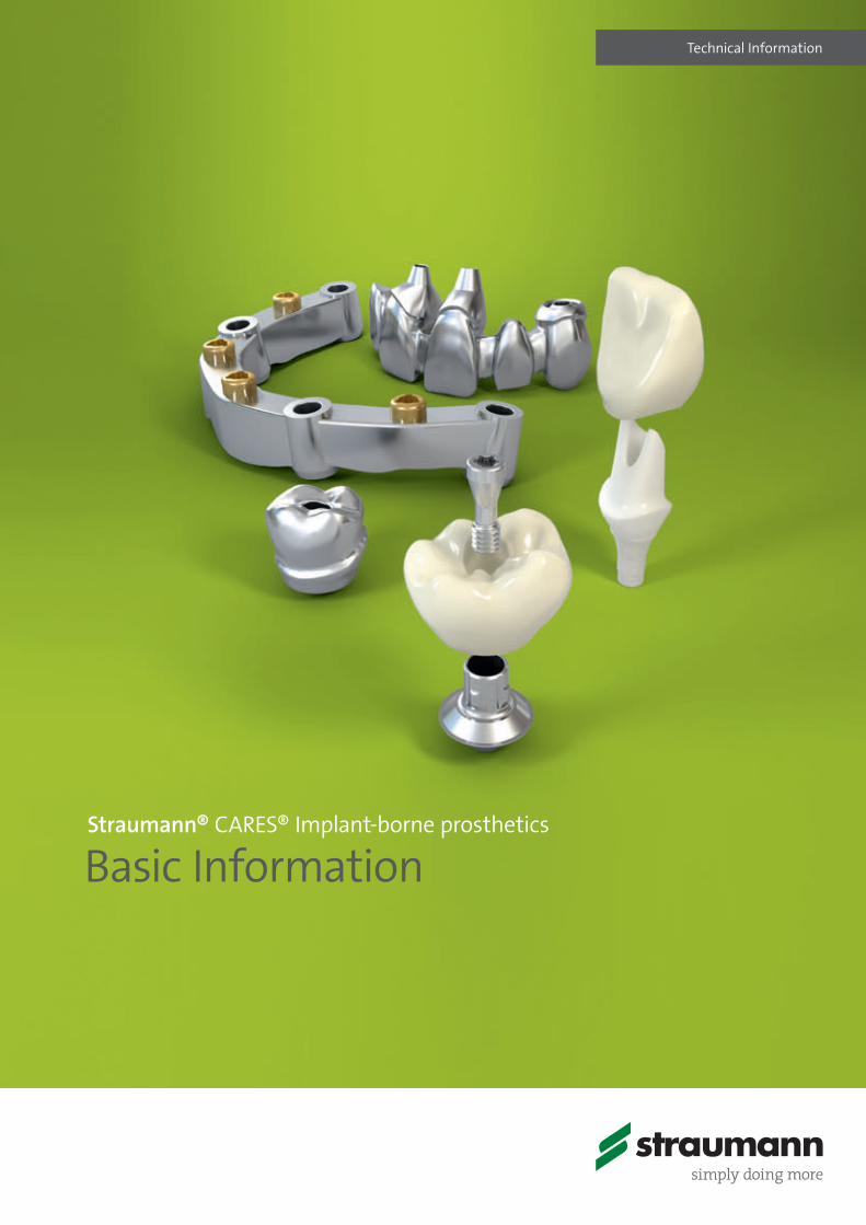
Technical Information
Straumann® CARES® Implant-borne prosthetics
Basic Information
15X.822_SbS_CARES.indd 1 01/12/2016 11:33

15X.822_SbS_CARES.indd 2 01/12/2016 11:33
1
Contents
1 Introduction 2
2 General information 32.1 Restorative options with the Straumann® CARES® portfolio 3
2.2 Technical requirements 5
2.3 System overview 6
3 Preparation for CARES® Visual 83.1 Fabrication of the master cast 8
3.2 Planning / Wax-up sleeves 9
3.3 Straumann® Scanbodies 13
4 Restorations, designing and finishing 154.1 Restoration: CARES® Abutment 15
4.2 CARES® X-Stream™ 20
4.3 Restoration: CARES® Screw-retained bridges and bars (SRBB) 24
5 Auxiliaries and instruments 385.1 SCS Screwdrivers 38
5.2 Ratchet and Torque control device 38
5.3 Polishing aids and analog holder 38
5.4 Auxiliaries for bar matrices 39
5.5 Wax-up kits 39
5.6 Bar male and female components 39
6 Appendix 406.1 Related documentation 40
Straumann® CARES® Screw-retained bridge and bar – Service and process 40
7 Important guidelines 41
15X.822_SbS_CARES.indd 1 01/12/2016 11:33
2
1 Introduction
Purpose of this guideThis guide was created for dental technicians working with the Straumann® CARES® Visual software for designing customized abutments, bars and screw-retained bridges.
Additionally, it provides complementary information regarding the conventional working steps in the dental laboratory when working with the Straumann® CARES® CADCAM system e.g. correct handling of the scanbodies, wax-up sleeves, etc.
Additional brochures are: ѹ Basic information on Tooth prosthetic procedures, 152.821 ѹ Basic Procedure Straumann® CARES® System, 701098 ѹ Straumann® CARES® 8.8, 490.020/en
All of the described devices are CAD-derived and CAM-manufac-tured. Straumann® CARES® Visual supports you designing the de-vices within indication-related conditions.
Instructions provided are insufficient to serve as the only means for processing and placing Straumann® CARES® Implant-borne prosthetics related components. Only those dental professionals thoroughly trained in dental restorations should be processing and placing these devices. Processing and placing Straumann® CARES® Implant-borne prosthetics and related components without proper training may lead to failure of the restoration. Restoration failure may lead to restoration removal or other complications.Failure to follow the procedures outlined in these instructions may harm the patient and/or lead to any or all of the following compli-cations:
ѹ Aspiration or swallowing of a component ѹ Breakage ѹ Infection
Note ѹ Implant-borne superstructures require optimal oral
hygiene on the part of the patient. This must be considered by all involved parties when planning and designing the restoration.
ѹ Consult the brochure Basic Information on the Sur-gical Procedures, 152.754 for information on indica-tions and contraindications of Straumann® Dental implants, such as required minimum number of implants, implant type, diameter and loading pro-tocols.
15X.822_SbS_CARES.indd 2 01/12/2016 11:33
3
2 General information
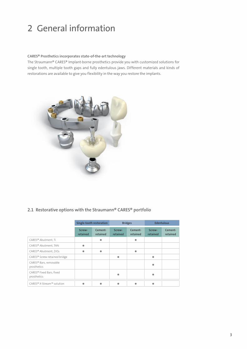
CARES® Prosthetics incorporates state-of-the-art technology The Straumann® CARES® Implant-borne prosthetics provide you with customized solutions for single tooth, multiple tooth gaps and fully edentulous jaws. Different materials and kinds of restorations are available to give you flexibility in the way you restore the implants.
2.1 Restorative options with the Straumann® CARES® portfolio
Single-tooth restoration Bridges Edentulous
Screw- retained
Cement- retained
Screw- retained
Cement- retained
Screw- retained
Cement- retained
CARES® Abutment, Ti
CARES® Abutment, TAN
CARES® Abutment, ZrO2
CARES® Screw-retained bridge
CARES® Bars, removable prosthetics
CARES® Fixed Bars, fixed prosthetics
CARES® X-Stream™ solution
15X.822_SbS_CARES.indd 3 01/12/2016 11:33
4
CARES® X-Stream™ The one-step prosthetic solution: 1 scan, 1 design, 1 deliveryCARES® X-Stream™ is an innovative example of an efficient digital workflow, streamlining clinical steps and simplifying long processes, while ensuring high quality prosthetics.
CARES® X-Stream™ provides a full prosthetic solution, flexible in use, to restore Straumann implants. With only one scan and one simultaneous and adaptive prosthetic element design, all required prosthetic components (e.g. Variobase® Abutments and their relevant bridge) are manufactured in the Straumann validated environment and arrive together in one delivery with an excellent fit of the components. This optimization of the necessary processing steps reduces turnaround time and related costs considerably.
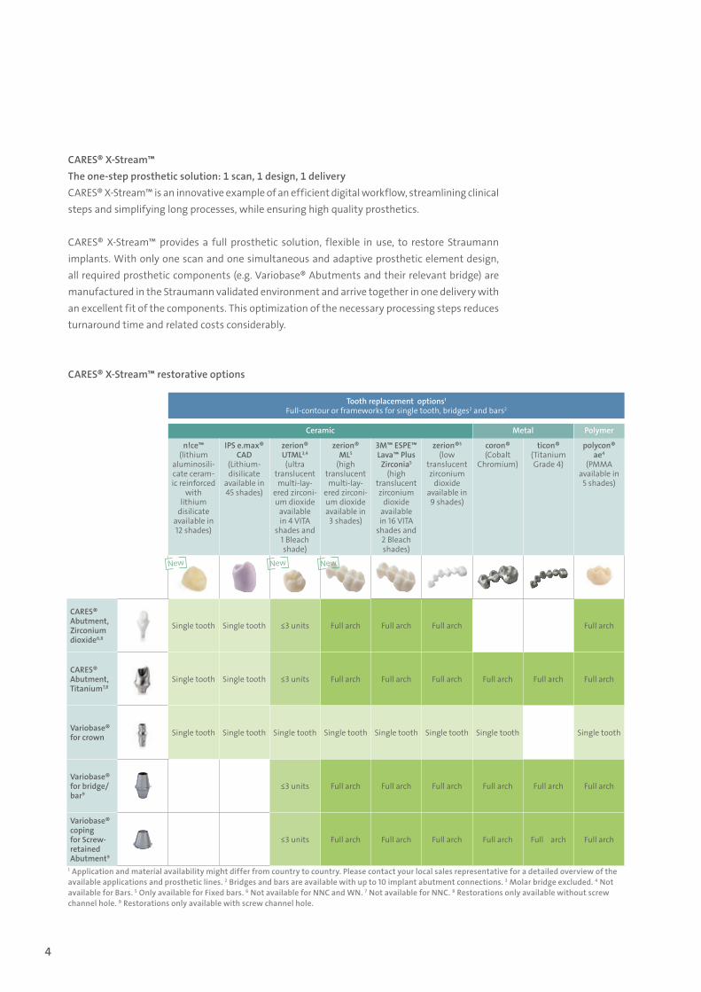
CARES® X-Stream™ restorative options
1 Application and material availability might differ from country to country. Please contact your local sales representative for a detailed overview of the available applications and prosthetic lines. 2 Bridges and bars are available with up to 10 implant abutment connections. 3 Molar bridge excluded. 4 Not available for Bars. 5 Only available for Fixed bars. 6 Not available for NNC and WN. 7 Not available for NNC. 8 Restorations only available without screw channel hole. 9 Restorations only available with screw channel hole.
Tooth replacement options1
Full-contour or frameworks for single tooth, bridges2 and bars2
Ceramic Metal Polymer
n!ce™(lithium
aluminosili-cate ceram-ic reinforced
with lithium
disilicate available in 12 shades)
IPS e.max® CAD
(Lithium- disilicate
available in 45 shades)
zerion® UTML3,4
(ultra translucent multi-lay-
ered zirconi-um dioxide
available in 4 VITA
shades and 1 Bleach shade)
zerion® ML5
(high translucent multi-lay-
ered zirconi-um dioxide available in
3 shades)
3M™ ESPE™ Lava™ Plus
Zirconia5
(high translucent zirconium
dioxide available in 16 VITA
shades and 2 Bleach shades)
zerion®5
(low translucent zirconium
dioxide available in 9 shades)
coron®(Cobalt
Chromium)
ticon®(Titanium Grade 4)
polycon® ae4
(PMMA available in
5 shades)
CARES® Abutment, Zirconium dioxide6,8
Single tooth Single tooth ≤3 units Full arch Full arch Full arch Full arch
CARES® Abutment, Titanium7,8
Single tooth Single tooth ≤3 units Full arch Full arch Full arch Full arch Full arch Full arch
Variobase® for crown Single tooth Single tooth Single tooth Single tooth Single tooth Single tooth Single tooth Single tooth
Variobase® for bridge/bar9
≤3 units Full arch Full arch Full arch Full arch Full arch Full arch
Variobase® coping for Screw- retained Abutment9
≤3 units Full arch Full arch Full arch Full arch Full arch Full arch
New New New
15X.822_SbS_CARES.indd 4 01/12/2016 11:34
5
2.2 Technical requirements
There are many ways to a CARES® Restoration. Therefore there are different “combinations” of infrastructure which are required for designing and ordering Straumann® CARES® Restorations:
Desktop scannerThe patient situation can be taken with a conventional impression tray. The dental laboratory scans the fabricated master model (preferably with removable segments) with a Straumann® approved desktop scanner.
SoftwareThe restoration is designed with Straumann® CARES® Visual or a Straumann® approved soft-ware (e.g. plug-in with Dental Wings Software Version 3.5, 3shape software version 2.8.8.7, or 3M™ Lava Scan ST with DWOS 7.0 installed), which is engineered to ensure that the restoration dimension complies with the Straumann® manufacturing capabilities.
Intraoral scanners (incl. repositionable implant analogs) The patient situation can be scanned with a Straumann® approved intraoral scanner (e.g. iTero™ or 3M™ True Definition Scanner. The data can be imported in the Straumann® approved software (e.g. Straumann® CARES® Visual version 5.IO or higher).
Straumann® CARES® Solution WS (working station) is a solution for customers who do not re-quire scanning the physical master cast and therefore do not have to invest in a desktop scanner.
Scan & Shape ServiceIf the dental laboratory does not have a Straumann® approved desktop scanner but wishes to order a Straumann® CARES® prosthetic component, they may send in their stl file, master model or wax-up of the restoration to the Straumann® CARES® Scan & Shape service.1
1 The CARES® Scan & Shape service is not available in all countries, please check with your local sales representative for further information. Additional information about the CARES® Scan & Shape service can be found in the brochures “The Way To Straumann® CARES® Abutments“ and “Straumann® CARES® Scan & Shape Process Guide”.
15X.822_SbS_CARES.indd 5 01/12/2016 11:34
6
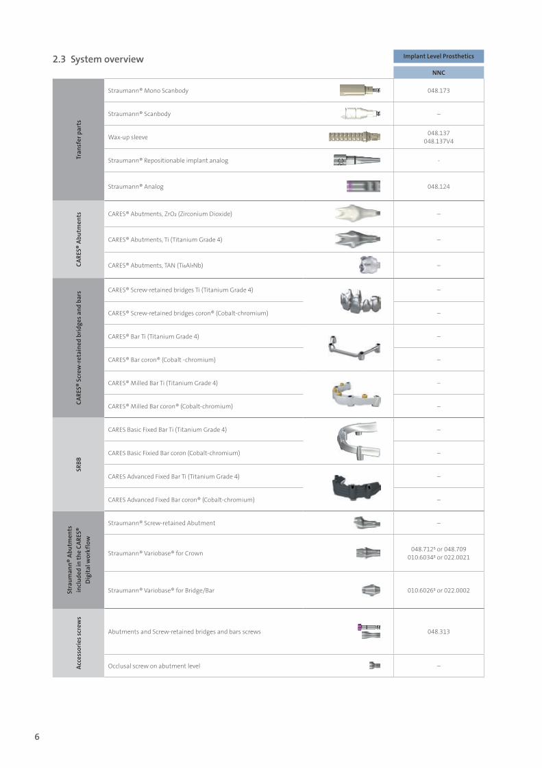
Implant Level Prosthetics Implant Level Prosthetics Abutment Level Prosthetics
NNC RN WN NC RC NC RCTr
ansf
er p
arts
Straumann® Mono Scanbody 048.173 048.168 048.169 025.2915 025.4915 025.0001 (D 4.6 mm) 025.0000 (D 3.5 mm) 025.0001 (D 4.6 mm)
Straumann® Scanbody – 048.068 048.069 025.2905 025.4905 – –
Wax-up sleeve 048.137048.137V4
048.088048.088-04
048.089048.098-04
025.2903025.2903-04
025.4903025.4903-04 – –
Straumann® Repositionable implant analog - 048.129 048.172 025.2102 025.4102 025.0007 (D 3.5 mm)025.0008 (D 4.6 mm) 025.0008 (D 4.6 mm)
Straumann® Analog 048.124 048.108048.124 048.171 025.2101 025.4101
023.2754 (0°, D 3.5 mm) 023.4756 (0°, D 4.6 mm)
023.4757 (angled, D 4.6 mm)
023.4756 (0°, D 4.6 mm) 023.4757 (angled, D 4.6 mm)
CARE
S® A
butm
ents CARES® Abutments, ZrO2 (Zirconium Dioxide) – 040.688 – 027.2650 027.4650 – –
CARES® Abutments, Ti (Titanium Grade 4) – 040.689 040.694 027.2620 027.4620 – –
CARES® Abutments, TAN (Ti6Al7Nb) – 010.6002 010.6003 010.6000 010.6001 – –
CARE
S® S
crew
-ret
aine
d br
idge
s and
bar
s CARES® Screw-retained bridges Ti (Titanium Grade 4) – 010.1076 to 010.1090
CARES® Screw-retained bridges coron® (Cobalt-chromium) – 010.1051 to 010.1065
CARES® Bar Ti (Titanium Grade 4) – 010.1091 to 010.1099
CARES® Bar coron® (Cobalt -chromium) – 010.1065 to 010.1074
CARES® Milled Bar Ti (Titanium Grade 4) – 010.1149 to 010.1157
CARES® Milled Bar coron® (Cobalt-chromium) – 010.1140 to 010.1148
SRBB
CARES Basic Fixed Bar Ti (Titanium Grade 4) – 010.113 to 010.1121
CARES Basic Fixied Bar coron (Cobalt-chromium) – 010.1104 to 010.112
CARES Advanced Fixed Bar Ti (Titanium Grade 4) – 010.1131 to 010.1139
CARES Advanced Fixed Bar coron® (Cobalt-chromium) – 010.1122 to 101.1130
Stra
uman
n® A
butm
ents
in
clud
ed in
the
CARE
S®
Dig
ital
wor
kflo
w
Straumann® Screw-retained Abutment – – – – – 022.2745 to 022.2758 022.4745 to 022.4755
Straumann® Variobase® for Crown 048.7125 or 048.709010.60345 or 022.0021
048.7135 or 048.710
010.60355 or 022.0022
048.7145 or 048.711
010.60365 or 022.0023
022.26535 or 025.2921
010.60385 or 022.0027
022.46535 or 025.4921
010.60375 or 022.0026
– –
Straumann® Variobase® for Bridge/Bar 010.60265 or 022.0002 010.60275 or 022.0003
010.60285 or 022.0004
010.60245 or 022.0000
010.60255 or 022.0001
010.60235 (D 4.6 mm)or 023.0001 (D 4 mm)010.60225 (D 3.5 mm)or 023.000 (3.5 mm)
010.60235 (D 4.6 mm)or 023.0001 (D 4.6 mm)
Acce
ssor
ies s
crew
s
Abutments and Screw-retained bridges and bars screws 048.313 048.3541048.3562,3 048.3562,3
025.49061025.49002025.29263
025.49061025.49002025.29263
NC/RC Screw for Screw-retained abutment straight 0°, GH 1 mm: 023.4749
straight 0°, GH 2.5 mm: 023.4750straight 0°, GH 4 mm: 023.4760
angled, 17°/30°: 025.0002
Occlusal screw on abutment level – – – – – 023.47634
2.3 System overview
15X.822_SbS_CARES.indd 6 01/12/2016 11:34
7
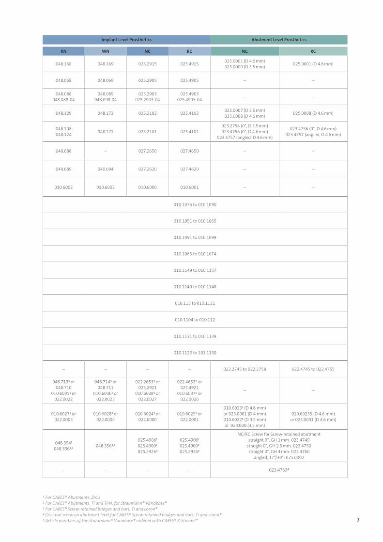
Implant Level Prosthetics Implant Level Prosthetics Abutment Level Prosthetics
NNC RN WN NC RC NC RC
Tran
sfer
par
ts
Straumann® Mono Scanbody 048.173 048.168 048.169 025.2915 025.4915 025.0001 (D 4.6 mm) 025.0000 (D 3.5 mm) 025.0001 (D 4.6 mm)
Straumann® Scanbody – 048.068 048.069 025.2905 025.4905 – –
Wax-up sleeve 048.137048.137V4
048.088048.088-04
048.089048.098-04
025.2903025.2903-04
025.4903025.4903-04 – –
Straumann® Repositionable implant analog - 048.129 048.172 025.2102 025.4102 025.0007 (D 3.5 mm)025.0008 (D 4.6 mm) 025.0008 (D 4.6 mm)
Straumann® Analog 048.124 048.108048.124 048.171 025.2101 025.4101
023.2754 (0°, D 3.5 mm) 023.4756 (0°, D 4.6 mm)
023.4757 (angled, D 4.6 mm)
023.4756 (0°, D 4.6 mm) 023.4757 (angled, D 4.6 mm)
CARE
S® A
butm
ents CARES® Abutments, ZrO2 (Zirconium Dioxide) – 040.688 – 027.2650 027.4650 – –
CARES® Abutments, Ti (Titanium Grade 4) – 040.689 040.694 027.2620 027.4620 – –
CARES® Abutments, TAN (Ti6Al7Nb) – 010.6002 010.6003 010.6000 010.6001 – –
CARE
S® S
crew
-ret
aine
d br
idge
s and
bar
s CARES® Screw-retained bridges Ti (Titanium Grade 4) – 010.1076 to 010.1090
CARES® Screw-retained bridges coron® (Cobalt-chromium) – 010.1051 to 010.1065
CARES® Bar Ti (Titanium Grade 4) – 010.1091 to 010.1099
CARES® Bar coron® (Cobalt -chromium) – 010.1065 to 010.1074
CARES® Milled Bar Ti (Titanium Grade 4) – 010.1149 to 010.1157
CARES® Milled Bar coron® (Cobalt-chromium) – 010.1140 to 010.1148
SRBB
CARES Basic Fixed Bar Ti (Titanium Grade 4) – 010.113 to 010.1121
CARES Basic Fixied Bar coron (Cobalt-chromium) – 010.1104 to 010.112
CARES Advanced Fixed Bar Ti (Titanium Grade 4) – 010.1131 to 010.1139
CARES Advanced Fixed Bar coron® (Cobalt-chromium) – 010.1122 to 101.1130
Stra
uman
n® A
butm
ents
in
clud
ed in
the
CARE
S®
Dig
ital
wor
kflo
w
Straumann® Screw-retained Abutment – – – – – 022.2745 to 022.2758 022.4745 to 022.4755
Straumann® Variobase® for Crown 048.7125 or 048.709010.60345 or 022.0021
048.7135 or 048.710
010.60355 or 022.0022
048.7145 or 048.711
010.60365 or 022.0023
022.26535 or 025.2921
010.60385 or 022.0027
022.46535 or 025.4921
010.60375 or 022.0026
– –
Straumann® Variobase® for Bridge/Bar 010.60265 or 022.0002 010.60275 or 022.0003
010.60285 or 022.0004
010.60245 or 022.0000
010.60255 or 022.0001
010.60235 (D 4.6 mm)or 023.0001 (D 4 mm)010.60225 (D 3.5 mm)or 023.000 (3.5 mm)
010.60235 (D 4.6 mm)or 023.0001 (D 4.6 mm)
Acce
ssor
ies s
crew
s
Abutments and Screw-retained bridges and bars screws 048.313 048.3541048.3562,3 048.3562,3
025.49061025.49002025.29263
025.49061025.49002025.29263
NC/RC Screw for Screw-retained abutment straight 0°, GH 1 mm: 023.4749
straight 0°, GH 2.5 mm: 023.4750straight 0°, GH 4 mm: 023.4760
angled, 17°/30°: 025.0002
Occlusal screw on abutment level – – – – – 023.47634
1 For CARES® Abutments, ZrO22 For CARES® Abutments, Ti and TAN; for Straumann® Variobase® 3 For CARES® Screw-retained bridges and bars, Ti and coron® 4 Occlusal screw on abutment level for CARES® Screw-retained bridges and bars, Ti and coron® 5 Article numbers of the Straumann® Variobase® ordered with CARES® X-Stream™
15X.822_SbS_CARES.indd 7 01/12/2016 11:34
8
Pre-conditions ѹ The tooth shade has been identified and noted
(via color chart or digital measuring device). ѹ Impression has been taken.
Both, shade information and impression were sent to the dental lab.
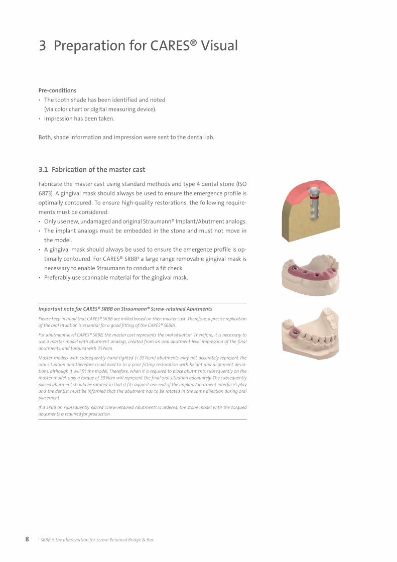
3.1 Fabrication of the master cast
Fabricate the master cast using standard methods and type 4 dental stone (ISO 6873). A gingival mask should always be used to ensure the emergence profile is optimally contoured. To ensure high-quality restorations, the following require-ments must be considered: ѹ Only use new, undamaged and original Straumann® Implant/Abutment analogs. ѹ The implant analogs must be embedded in the stone and must not move in
the model. ѹ A gingival mask should always be used to ensure the emergence profile is op-
timally contoured. For CARES® SRBB1 a large range removable gingival mask is necessary to enable Straumann to conduct a fit check.
ѹ Preferably use scannable material for the gingival mask.
3 Preparation for CARES® Visual
1 SRBB is the abbreviation for Screw-Retained Bridge & Bar.
Important note for CARES® SRBB on Straumann® Screw-retained Abutments
Please keep in mind that CARES® SRBB are milled based on their master cast. Therefore, a precise replication of the oral situation is essential for a good fitting of the CARES® SRBBs.
For abutment-level CARES® SRBB, the master cast represents the oral situation. Therefore, it is necessary to use a master model with abutment analogs, created from an oral abutment-level impression of the final abutments, and torqued with 35 Ncm.
Master models with subsequently hand-tighted (< 35 Ncm) abutments may not accurately represent the oral situation and therefore could lead to to a poor fitting restoration with height and alignment devia-tions, although it will fit the model. Therefore, when it is required to place abutments subsequently on the master model, only a torque of 35 Ncm will represent the final oral situation adequately. The subsequently placed abutment should be rotated so that it fits against one end of the implant/abutment interface’s play and the dentist must be informed that the abutment has to be rotated in the same direction during oral placement.
If a SRBB on subsequently placed Screw-retained Abutments is ordered, the stone model with the torqued abutments is required for production.
15X.822_SbS_CARES.indd 8 01/12/2016 11:34
9
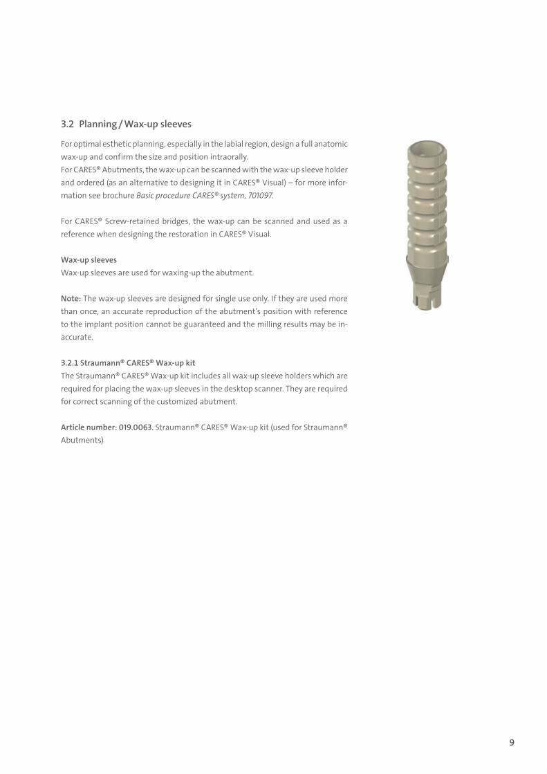
3.2 Planning / Wax-up sleeves
For optimal esthetic planning, especially in the labial region, design a full anatomic wax-up and confirm the size and position intraorally. For CARES® Abutments, the wax-up can be scanned with the wax-up sleeve holder and ordered (as an alternative to designing it in CARES® Visual) – for more infor-mation see brochure Basic procedure CARES® system, 701097.
For CARES® Screw-retained bridges, the wax-up can be scanned and used as a reference when designing the restoration in CARES® Visual.
Wax-up sleeves Wax-up sleeves are used for waxing-up the abutment.
Note: The wax-up sleeves are designed for single use only. If they are used more than once, an accurate reproduction of the abutment’s position with reference to the implant position cannot be guaranteed and the milling results may be in-accurate.
3.2.1 Straumann® CARES® Wax-up kitThe Straumann® CARES® Wax-up kit includes all wax-up sleeve holders which are required for placing the wax-up sleeves in the desktop scanner. They are required for correct scanning of the customized abutment.
Article number: 019.0063. Straumann® CARES® Wax-up kit (used for Straumann® Abutments)
15X.822_SbS_CARES.indd 9 01/12/2016 11:34
10
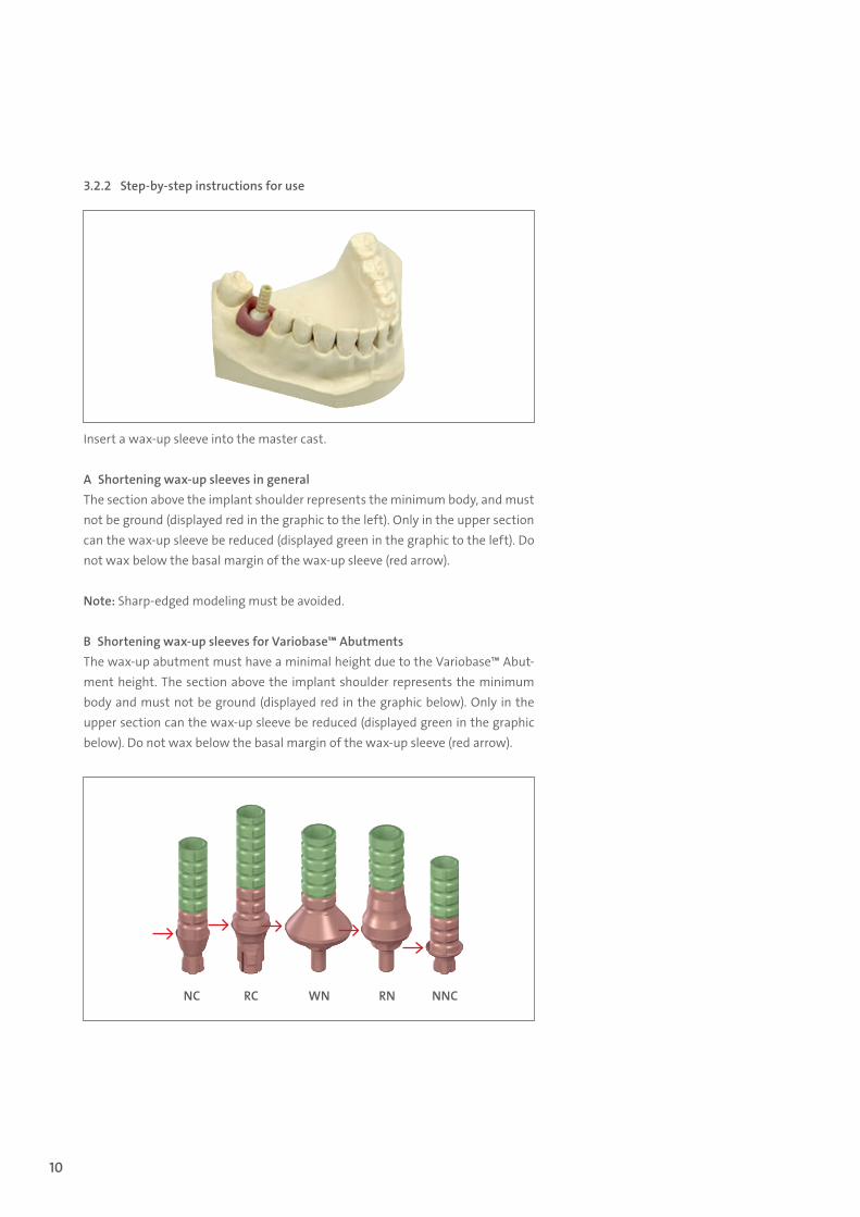
3.2.2 Step-by-step instructions for use
Insert a wax-up sleeve into the master cast.
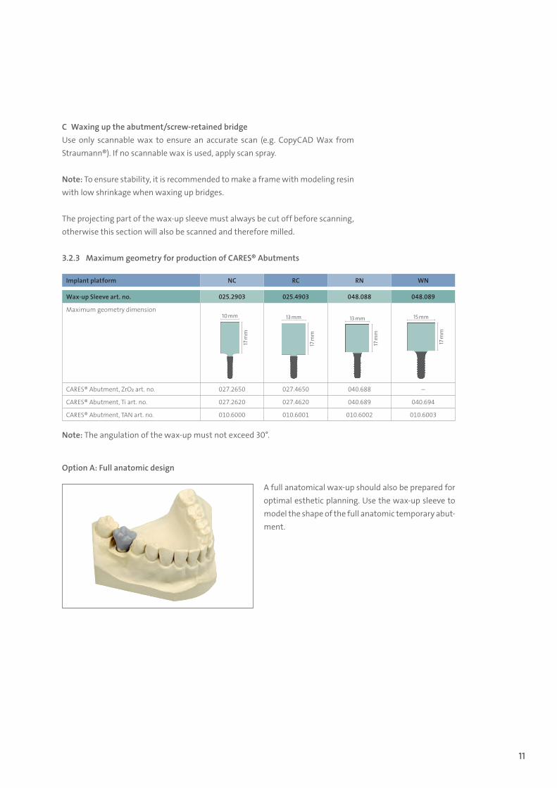
A Shortening wax-up sleeves in generalThe section above the implant shoulder represents the minimum body, and must not be ground (displayed red in the graphic to the left). Only in the upper section can the wax-up sleeve be reduced (displayed green in the graphic to the left). Do not wax below the basal margin of the wax-up sleeve (red arrow).
Note: Sharp-edged modeling must be avoided.
B Shortening wax-up sleeves for Variobase™ AbutmentsThe wax-up abutment must have a minimal height due to the Variobase™ Abut-ment height. The section above the implant shoulder represents the minimum body and must not be ground (displayed red in the graphic below). Only in the upper section can the wax-up sleeve be reduced (displayed green in the graphic below). Do not wax below the basal margin of the wax-up sleeve (red arrow).
NC RC WN RN NNC
15X.822_SbS_CARES.indd 10 01/12/2016 11:34
11
C Waxing up the abutment/screw-retained bridgeUse only scannable wax to ensure an accurate scan (e.g. CopyCAD Wax from Straumann®). If no scannable wax is used, apply scan spray.
Note: To ensure stability, it is recommended to make a frame with modeling resin with low shrinkage when waxing up bridges.
The projecting part of the wax-up sleeve must always be cut off before scanning, otherwise this section will also be scanned and therefore milled.
3.2.3 Maximum geometry for production of CARES® Abutments
Option A: Full anatomic design
A full anatomical wax-up should also be prepared for optimal esthetic planning. Use the wax-up sleeve to model the shape of the full anatomic temporary abut-ment.
Implant platform NC RC RN WN
Wax-up Sleeve art. no. 025.2903 025.4903 048.088 048.089
Maximum geometry dimension10 mm
17 m
m
13 mm17
mm
13 mm
17 m
m
15 mm
17 m
m
CARES® Abutment, ZrO2 art. no. 027.2650 027.4650 040.688 –
CARES® Abutment, Ti art. no. 027.2620 027.4620 040.689 040.694
CARES® Abutment, TAN art. no. 010.6000 010.6001 010.6002 010.6003
Note: The angulation of the wax-up must not exceed 30°.
15X.822_SbS_CARES.indd 11 01/12/2016 11:34
12
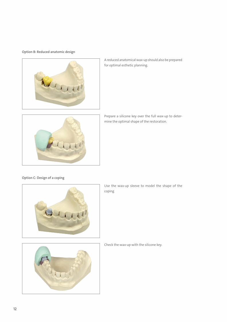
Option B: Reduced anatomic design
Option C: Design of a coping
A reduced anatomical wax-up should also be prepared for optimal esthetic planning.
Prepare a silicone key over the full wax-up to deter-mine the optimal shape of the restoration.
Use the wax-up sleeve to model the shape of the coping
Check the wax-up with the silicone key.
15X.822_SbS_CARES.indd 12 01/12/2016 11:34
13
3.3 Straumann® Scanbodies
Product descriptionThe Straumann® Scan Bodies represent the position and orientation of the re-spective dental implant or analog in CADCAM scanning procedures. This helps the CADCAM software to correctly align the subsequent CADCAM restorations.
Product overviewStraumann® offers two different types of scanbodies which differ in terms of handling and scanner compatibility: ѹ Straumann® CARES® Mono scanbody (on implant and abutment level) ѹ Straumann® Scanbody
Make sure to select the correct Straumann® Scanbody according to the software version (see compatibility chart on page 8).
Note: The Straumann® Scanbodies and all components are intended for single use only. Multiple use of a scanbody can lead to inaccurate results. Make sure the stability of the dental implant is sufficient to support the screwing / unscrewing operations of the scanbodies. Scan spray is not required at any time.
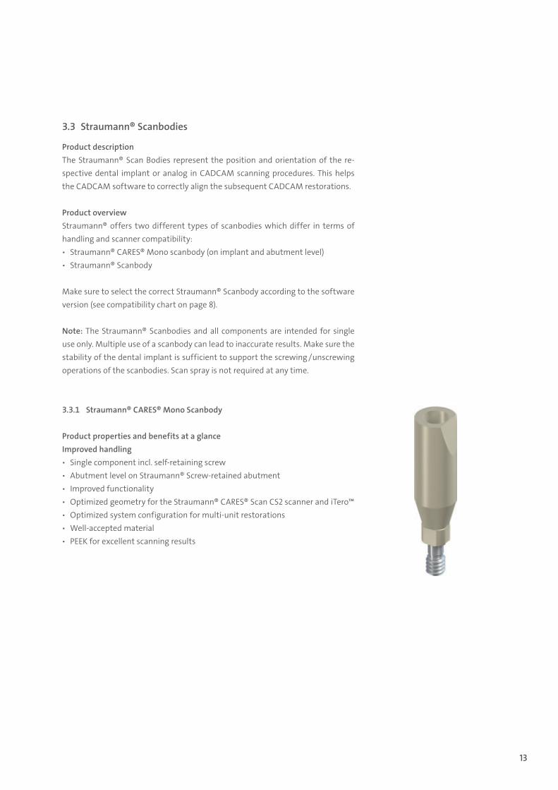
3.3.1 Straumann® CARES® Mono Scanbody
Product properties and benefits at a glanceImproved handling ѹ Single component incl. self-retaining screw ѹ Abutment level on Straumann® Screw-retained abutment ѹ Improved functionality ѹ Optimized geometry for the Straumann® CARES® Scan CS2 scanner and iTero™ ѹ Optimized system configuration for multi-unit restorations ѹ Well-accepted material ѹ PEEK for excellent scanning results
15X.822_SbS_CARES.indd 13 01/12/2016 11:34
14
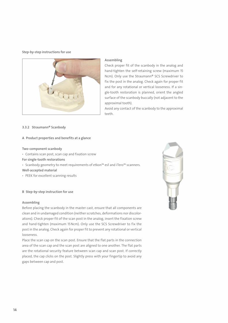
Step-by-step instructions for use
AssemblingCheck proper fit of the scanbody in the analog and hand-tighten the self-retaining screw (maximum 15 Ncm). Only use the Straumann® SCS Screwdriver to fix the post in the analog. Check again for proper fit and for any rotational or vertical looseness. If a sin-gle-tooth restoration is planned, orient the angled surface of the scanbody buccally (not adjacent to the approximal tooth). Avoid any contact of the scanbody to the approximal teeth.
3.3.2 Straumann® Scanbody
A Product properties and benefits at a glance
Two-component scanbody ѹ Contains scan post, scan cap and fixation screw
For single-tooth restorations ѹ Scanbody geometry to meet requirements of etkon™ es1 and iTero™ scanners.
Well-accepted material ѹ PEEK for excellent scanning results
B Step-by-step instruction for use
AssemblingBefore placing the scanbody in the master cast, ensure that all components are clean and in undamaged condition (neither scratches, deformations nor discolor-ations). Check proper fit of the scan post in the analog, insert the fixation screw and hand-tighten (maximum 15 Ncm). Only use the SCS Screwdriver to fix the post in the analog. Check again for proper fit to prevent any rotational or vertical looseness.Place the scan cap on the scan post. Ensure that the flat parts in the connection area of the scan cap and the scan post are aligned to one another. The flat parts are the rotational security feature between scan cap and scan post. If correctly placed, the cap clicks on the post. Slightly press with your fingertip to avoid any gaps between cap and post.
15X.822_SbS_CARES.indd 14 01/12/2016 11:34
15
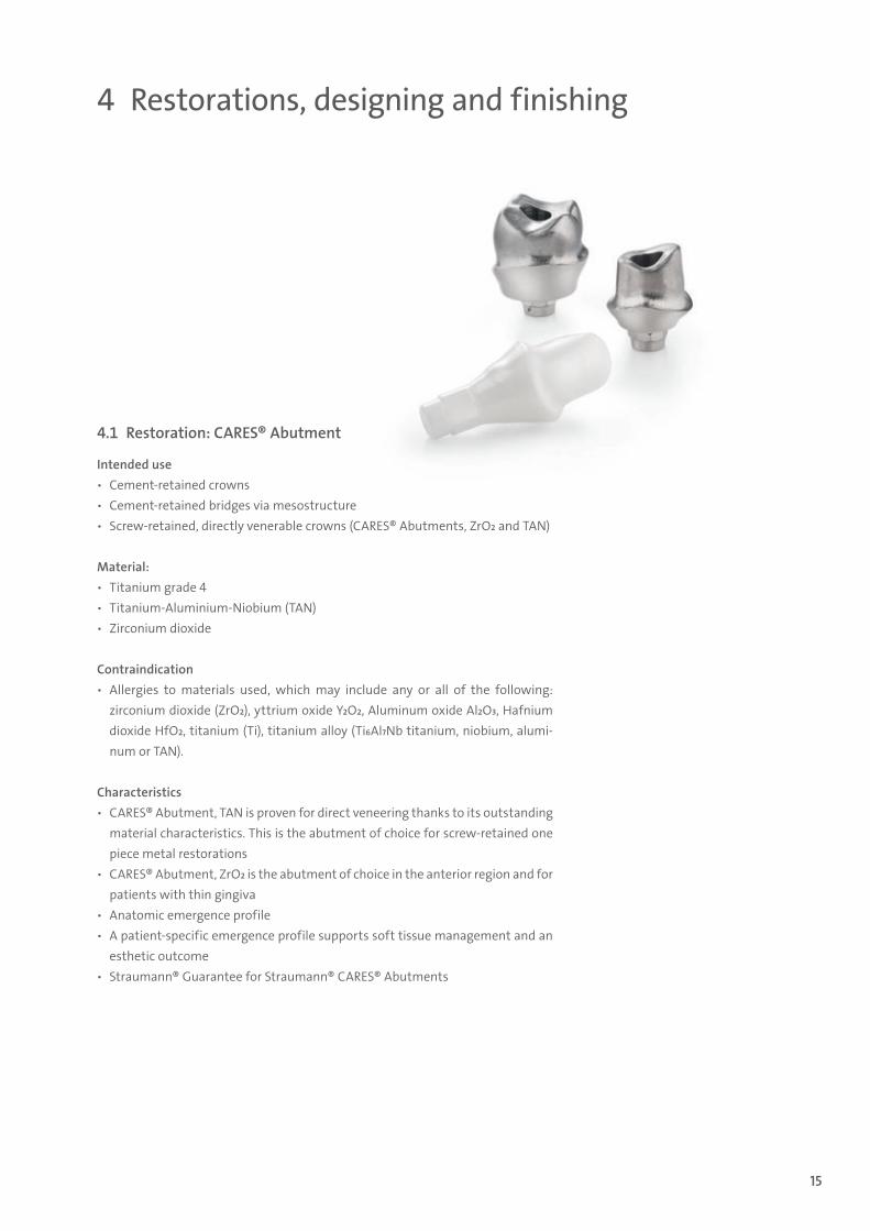
4 Restorations, designing and finishing
4.1 Restoration: CARES® Abutment
Intended use ѹ Cement-retained crowns ѹ Cement-retained bridges via mesostructure ѹ Screw-retained, directly venerable crowns (CARES® Abutments, ZrO2 and TAN)
Material: ѹ Titanium grade 4 ѹ Titanium-Aluminium-Niobium (TAN) ѹ Zirconium dioxide
Contraindication ѹ Allergies to materials used, which may include any or all of the following:
zirconium dioxide (ZrO2), yttrium oxide Y2O2, Aluminum oxide Al2O3, Hafnium dioxide HfO2, titanium (Ti), titanium alloy (Ti6Al7Nb titanium, niobium, alumi-num or TAN).
Characteristics ѹ CARES® Abutment, TAN is proven for direct veneering thanks to its outstanding
material characteristics. This is the abutment of choice for screw-retained one piece metal restorations
ѹ CARES® Abutment, ZrO2 is the abutment of choice in the anterior region and for patients with thin gingiva
ѹ Anatomic emergence profile ѹ A patient-specific emergence profile supports soft tissue management and an
esthetic outcome ѹ Straumann® Guarantee for Straumann® CARES® Abutments
15X.822_SbS_CARES.indd 15 01/12/2016 11:34
16
4.1.1 Designing CARES® Workflow
Step 1 – Preparation for CARES® VisualFollow the preparation requirements according to chapter 3Step 2 – Designing with CARES® VisualDesign the restoration according the brochure Straumann® CARES® Visual, 152.825
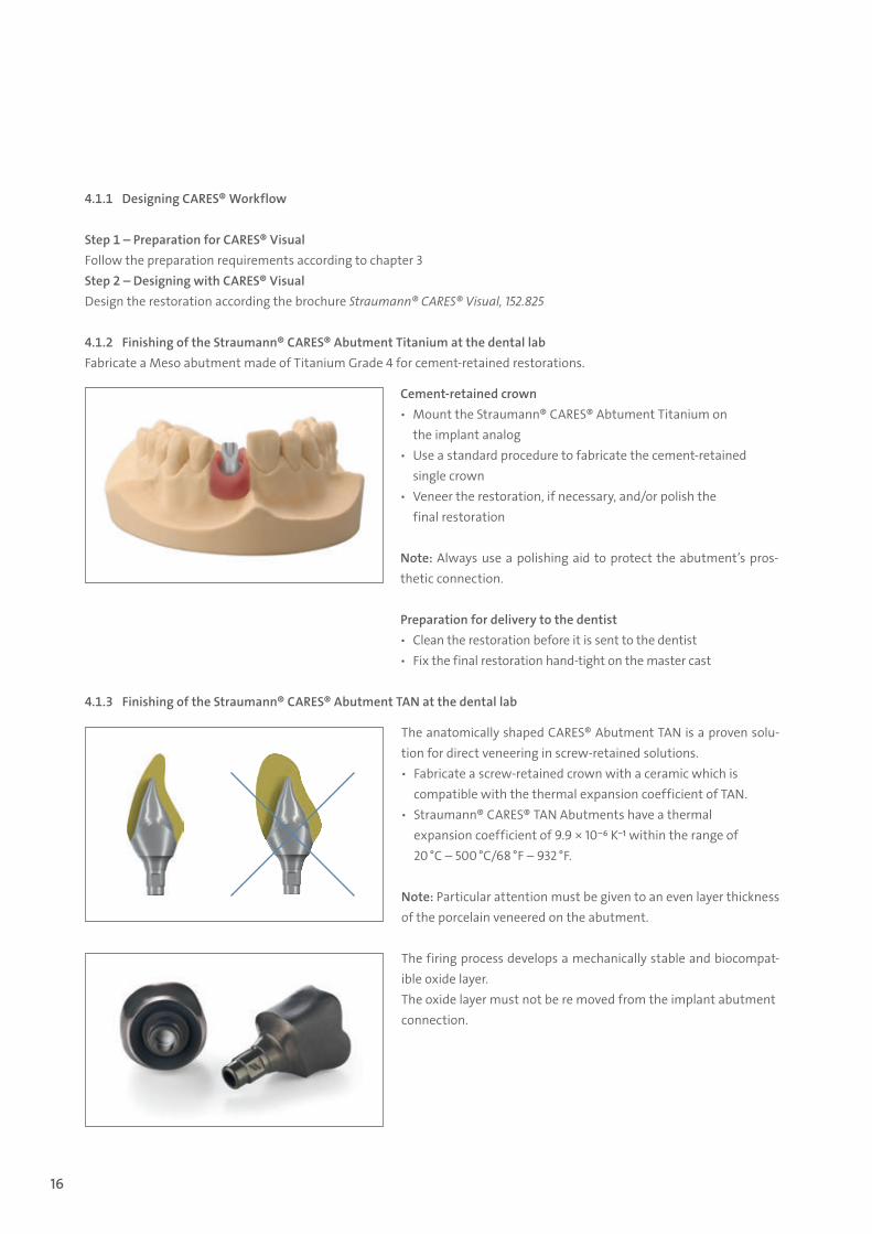
4.1.2 Finishing of the Straumann® CARES® Abutment Titanium at the dental labFabricate a Meso abutment made of Titanium Grade 4 for cement-retained restorations.
Cement-retained crown ѹ Mount the Straumann® CARES® Abtument Titanium on
the implant analog ѹ Use a standard procedure to fabricate the cement-retained
single crown ѹ Veneer the restoration, if necessary, and/or polish the
final restoration
Note: Always use a polishing aid to protect the abutment’s pros-thetic connection.
Preparation for delivery to the dentist ѹ Clean the restoration before it is sent to the dentist ѹ Fix the final restoration hand-tight on the master cast
The anatomically shaped CARES® Abutment TAN is a proven solu-tion for direct veneering in screw-retained solutions. ѹ Fabricate a screw-retained crown with a ceramic which is
compatible with the thermal expansion coefficient of TAN. ѹ Straumann® CARES® TAN Abutments have a thermal
expansion coefficient of 9.9 × 10⁻⁶ K-1 within the range of 20 °C – 500 °C/68 °F – 932 °F.
Note: Particular attention must be given to an even layer thickness of the porcelain veneered on the abutment.
The firing process develops a mechanically stable and biocompat-ible oxide layer.The oxide layer must not be re moved from the implant abutment connection.
4.1.3 Finishing of the Straumann® CARES® Abutment TAN at the dental lab
15X.822_SbS_CARES.indd 16 01/12/2016 11:34
17
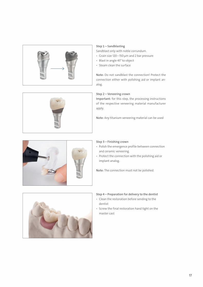
Step 1 – SandblastingSandblast only with noble corrundum. ѹ Grain size 120 – 150 µm and 2 bar pressure ѹ Blast in angle 45° to object ѹ Steam clean the surface
Note: Do not sandblast the connection! Protect the connection either with polishing aid or implant an-alog.
Step 2 – Veneering crownImportant: for this step, the processing instructions of the respective veneering material manufacturer apply.
Note: Any titanium veneering material can be used
Step 3 – Finishing crown ѹ Polish the emergence profile between connection
and ceramic veneering. ѹ Protect the connection with the polishing aid or
implant analog.
Note: The connection must not be polished.
Step 4 – Preparation for delivery to the dentist ѹ Clean the restoration before sending to the
dentist ѹ Screw the final restoration hand tight on the
master cast
15X.822_SbS_CARES.indd 17 01/12/2016 11:34
18
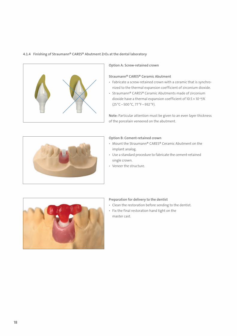
Option A: Screw-retained crown
Straumann® CARES® Ceramic Abutment ѹ Fabricate a screw-retained crown with a ceramic that is synchro-
nized to the thermal expansion coefficient of zirconium dioxide. ѹ Straumann® CARES® Ceramic Abutments made of zirconium
dioxide have a thermal expansion coefficient of 10.5 × 10⁻⁶/K (25 °C – 500 °C, 77 °F – 932 °F).
Note: Particular attention must be given to an even layer thickness of the porcelain veneered on the abutment.
4.1.4 Finishing of Straumann® CARES® Abutment ZrO2 at the dental laboratory
Option B: Cement-retained crown ѹ Mount the Straumann® CARES® Ceramic Abutment on the
implant analog. ѹ Use a standard procedure to fabricate the cement- retained
single crown. ѹ Veneer the structure.
Preparation for delivery to the dentist ѹ Clean the restoration before sending to the dentist. ѹ Fix the final restoration hand tight on the
master cast.
15X.822_SbS_CARES.indd 18 01/12/2016 11:34
19
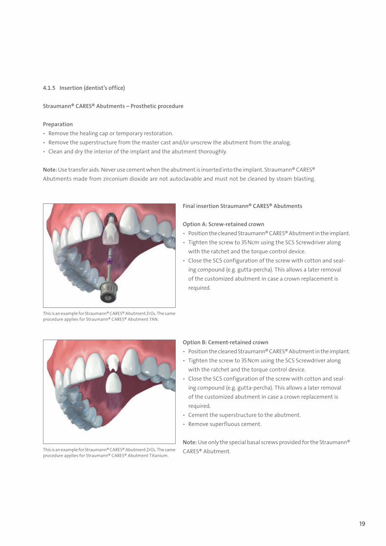
Final insertion Straumann® CARES® Abutments
Option A: Screw-retained crown ѹ Position the cleaned Straumann® CARES® Abutment in the implant. ѹ Tighten the screw to 35 Ncm using the SCS Screwdriver along
with the ratchet and the torque control device. ѹ Close the SCS configuration of the screw with cotton and seal-
ing compound (e.g. gutta-percha). This allows a later removal of the customized abutment in case a crown replacement is required.
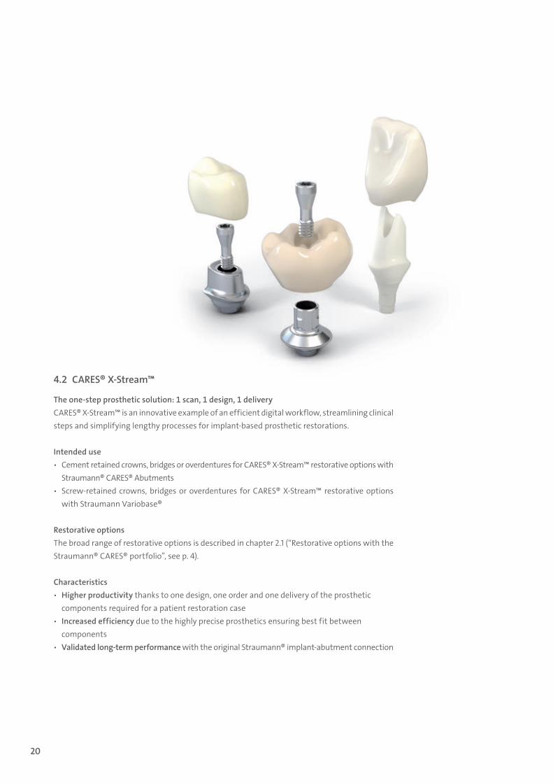
Option B: Cement-retained crown ѹ Position the cleaned Straumann® CARES® Abutment in the implant. ѹ Tighten the screw to 35 Ncm using the SCS Screwdriver along
with the ratchet and the torque control device. ѹ Close the SCS configuration of the screw with cotton and seal-
ing compound (e.g. gutta-percha). This allows a later removal of the customized abutment in case a crown replacement is required.
ѹ Cement the superstructure to the abutment. ѹ Remove superfluous cement.
Note: Use only the special basal screws provided for the Straumann® CARES® Abutment.
4.1.5 Insertion (dentist’s office)
Straumann® CARES® Abutments – Prosthetic procedure
Preparation ѹ Remove the healing cap or temporary restoration. ѹ Remove the superstructure from the master cast and/or unscrew the abutment from the analog. ѹ Clean and dry the interior of the implant and the abutment thoroughly.
Note: Use transfer aids. Never use cement when the abutment is inserted into the implant. Straumann® CARES® Abutments made from zirconium dioxide are not autoclavable and must not be cleaned by steam blasting.
This is an example for Straumann® CARES® Abutment ZrO2. The sameprocedure applies for Straumann® CARES® Abutment TAN.
This is an example for Straumann® CARES® Abutment ZrO2. The sameprocedure applies for Straumann® CARES® Abutment Titanium.
15X.822_SbS_CARES.indd 19 01/12/2016 11:34
20
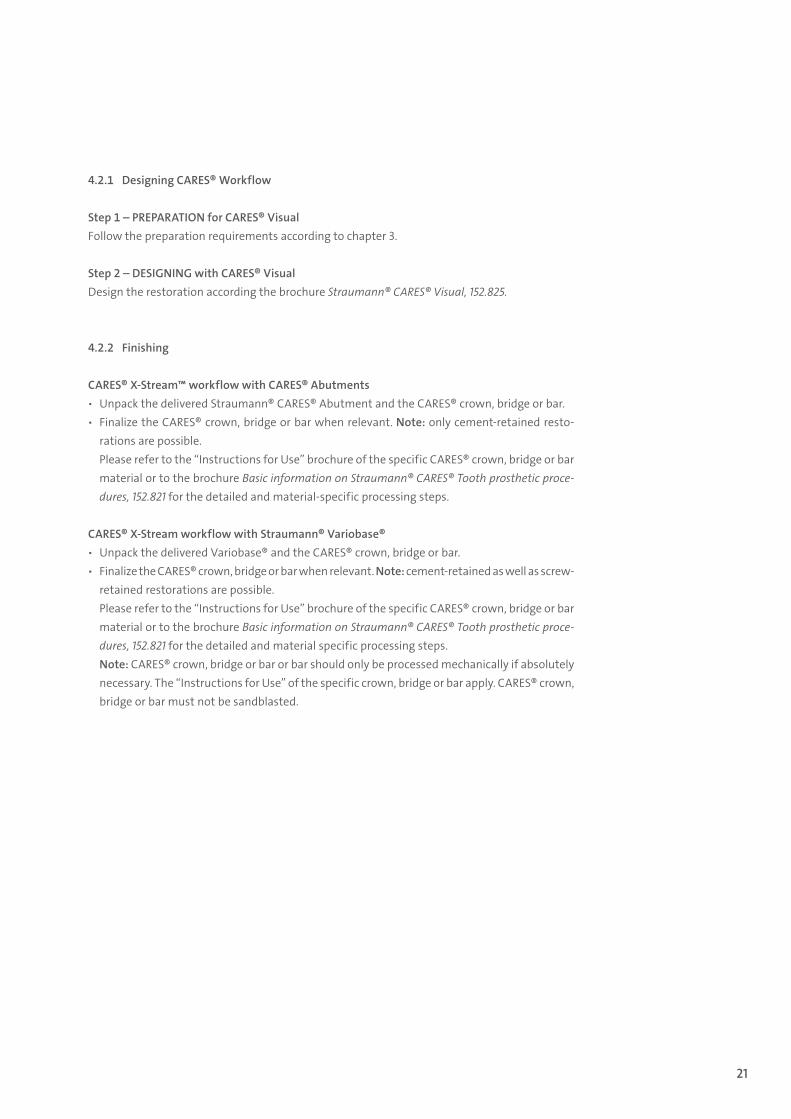
4.2 CARES® X-Stream™
The one-step prosthetic solution: 1 scan, 1 design, 1 deliveryCARES® X-Stream™ is an innovative example of an efficient digital workflow, streamlining clinical steps and simplifying lengthy processes for implant-based prosthetic restorations.
Intended use ѹ Cement retained crowns, bridges or overdentures for CARES® X-Stream™ restorative options with
Straumann® CARES® Abutments ѹ Screw-retained crowns, bridges or overdentures for CARES® X-Stream™ restorative options
with Straumann Variobase®
Restorative optionsThe broad range of restorative options is described in chapter 2.1 (“Restorative options with the Straumann® CARES® portfolio”, see p. 4).
Characteristics ѹ Higher productivity thanks to one design, one order and one delivery of the prosthetic
components required for a patient restoration case ѹ Increased efficiency due to the highly precise prosthetics ensuring best fit between
components ѹ Validated long-term performance with the original Straumann® implant-abutment connection
15X.822_SbS_CARES.indd 20 01/12/2016 11:34
21
4.2.1 Designing CARES® Workflow
Step 1 – PREPARATION for CARES® VisualFollow the preparation requirements according to chapter 3.
Step 2 – DESIGNING with CARES® VisualDesign the restoration according the brochure Straumann® CARES® Visual, 152.825.
4.2.2 Finishing
CARES® X-Stream™ workflow with CARES® Abutments ѹ Unpack the delivered Straumann® CARES® Abutment and the CARES® crown, bridge or bar. ѹ Finalize the CARES® crown, bridge or bar when relevant. Note: only cement-retained resto-
rations are possible.Please refer to the “Instructions for Use” brochure of the specific CARES® crown, bridge or bar material or to the brochure Basic information on Straumann® CARES® Tooth prosthetic proce-dures, 152.821 for the detailed and material-specific processing steps.
CARES® X-Stream workflow with Straumann® Variobase® ѹ Unpack the delivered Variobase® and the CARES® crown, bridge or bar. ѹ Finalize the CARES® crown, bridge or bar when relevant. Note: cement-retained as well as screw-
retained restorations are possible. Please refer to the “Instructions for Use” brochure of the specific CARES® crown, bridge or bar material or to the brochure Basic information on Straumann® CARES® Tooth prosthetic proce-dures, 152.821 for the detailed and material specific processing steps.Note: CARES® crown, bridge or bar or bar should only be processed mechanically if absolutely necessary. The “Instructions for Use” of the specific crown, bridge or bar apply. CARES® crown, bridge or bar must not be sandblasted.
15X.822_SbS_CARES.indd 21 01/12/2016 11:34
22
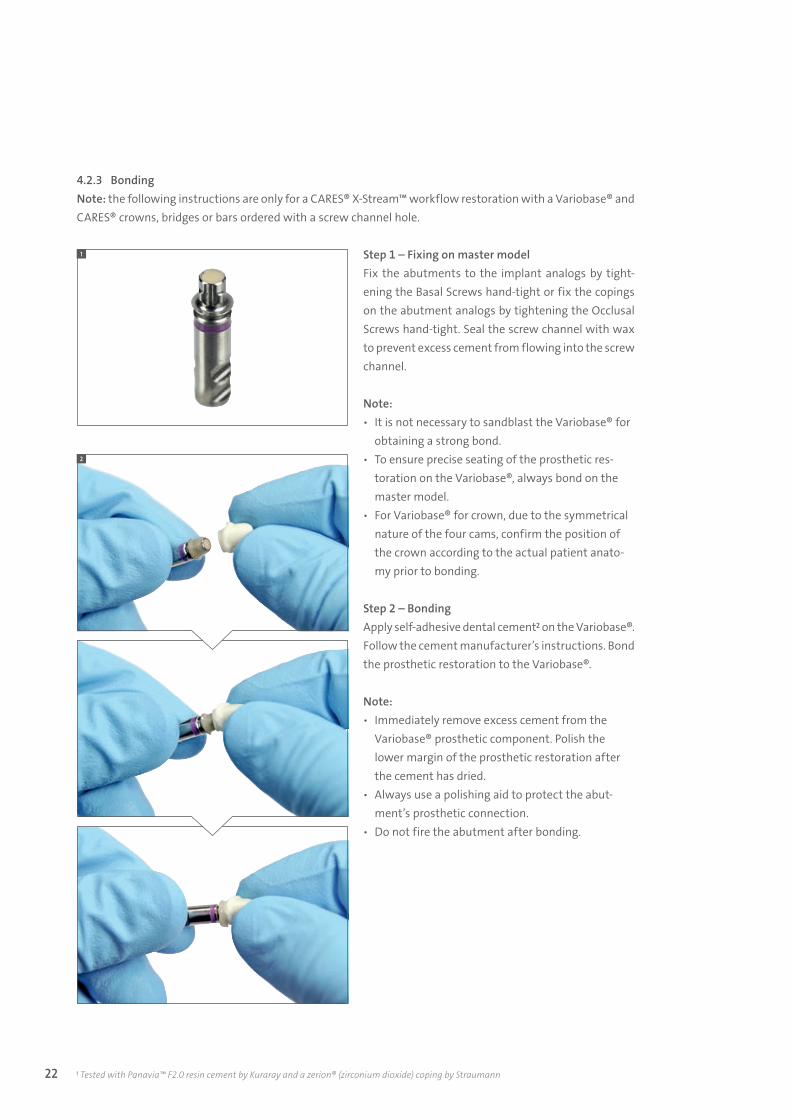
4.2.3 BondingNote: the following instructions are only for a CARES® X-Stream™ workflow restoration with a Variobase® and CARES® crowns, bridges or bars ordered with a screw channel hole.
Step 1 – Fixing on master modelFix the abutments to the implant analogs by tight-ening the Basal Screws hand-tight or fix the copings on the abutment analogs by tightening the Occlusal Screws hand-tight. Seal the screw channel with wax to prevent excess cement from flowing into the screw channel.
Note: ѹ It is not necessary to sandblast the Variobase® for
obtaining a strong bond. ѹ To ensure precise seating of the prosthetic res-
toration on the Variobase®, always bond on the master model.
ѹ For Variobase® for crown, due to the symmetrical nature of the four cams, confirm the position of the crown according to the actual patient anato-my prior to bonding.
Step 2 – BondingApply self-adhesive dental cement2 on the Variobase®. Follow the cement manufacturer’s instructions. Bond the prosthetic restoration to the Variobase®.
Note: ѹ Immediately remove excess cement from the
Variobase® prosthetic component. Polish the lower margin of the prosthetic restoration after the cement has dried.
ѹ Always use a polishing aid to protect the abut-ment’s prosthetic connection.
ѹ Do not fire the abutment after bonding.
1 Tested with Panavia™ F2.0 resin cement by Kuraray and a zerion® (zirconium dioxide) coping by Straumann
1
2
15X.822_SbS_CARES.indd 22 01/12/2016 11:34
23
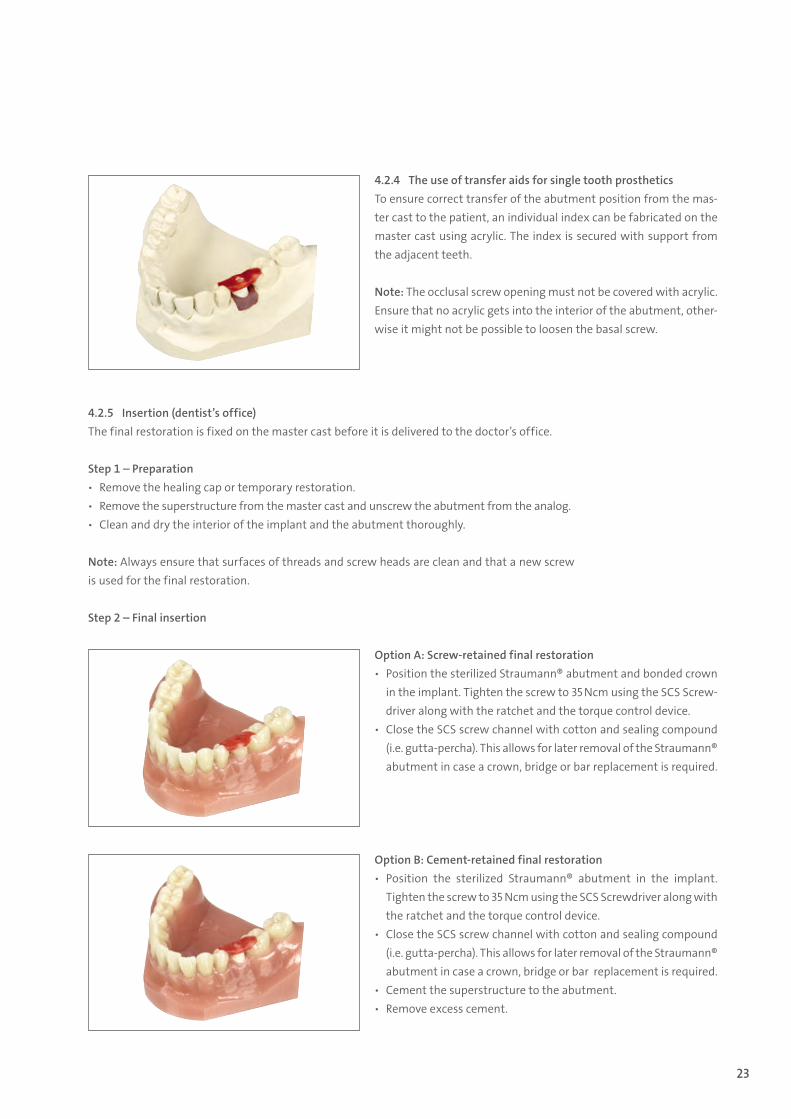
4.2.4 The use of transfer aids for single tooth prostheticsTo ensure correct transfer of the abutment position from the mas-ter cast to the patient, an individual index can be fabricated on the master cast using acrylic. The index is secured with support from the adjacent teeth.
Note: The occlusal screw opening must not be covered with acrylic. Ensure that no acrylic gets into the interior of the abutment, other-wise it might not be possible to loosen the basal screw.
Option A: Screw-retained final restoration ѹ Position the sterilized Straumann® abutment and bonded crown
in the implant. Tighten the screw to 35 Ncm using the SCS Screw-driver along with the ratchet and the torque control device.
ѹ Close the SCS screw channel with cotton and sealing compound (i.e. gutta-percha). This allows for later removal of the Straumann® abutment in case a crown, bridge or bar replacement is required.
Option B: Cement-retained final restoration ѹ Position the sterilized Straumann® abutment in the implant.
Tighten the screw to 35 Ncm using the SCS Screwdriver along with the ratchet and the torque control device.
ѹ Close the SCS screw channel with cotton and sealing compound (i.e. gutta-percha). This allows for later removal of the Straumann® abutment in case a crown, bridge or bar replacement is required.
ѹ Cement the superstructure to the abutment. ѹ Remove excess cement.
4.2.5 Insertion (dentist’s office)The final restoration is fixed on the master cast before it is delivered to the doctor’s office.
Step 1 – Preparation ѹ Remove the healing cap or temporary restoration. ѹ Remove the superstructure from the master cast and unscrew the abutment from the analog. ѹ Clean and dry the interior of the implant and the abutment thoroughly.
Note: Always ensure that surfaces of threads and screw heads are clean and that a new screw is used for the final restoration.
Step 2 – Final insertion
15X.822_SbS_CARES.indd 23 01/12/2016 11:34
24
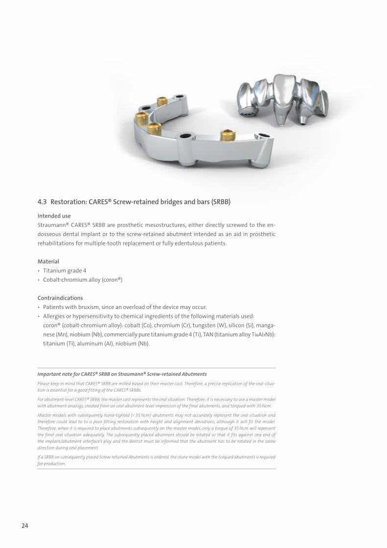
4.3 Restoration: CARES® Screw-retained bridges and bars (SRBB)
Intended use Straumann® CARES® SRBB are prosthetic mesostructures, either directly screwed to the en-dosseous dental implant or to the screw-retained abutment intended as an aid in prosthetic rehabilitations for multiple-tooth replacement or fully edentulous patients.
Material ѹ Titanium grade 4 ѹ Cobalt-chromium alloy (coron®)
Contraindications ѹ Patients with bruxism, since an overload of the device may occur. ѹ Allergies or hypersensitivity to chemical ingredients of the following materials used:
coron® (cobalt-chromium alloy): cobalt (Co), chromium (Cr), tungsten (W), silicon (Si), manga-nese (Mn), niobium (Nb), commercially pure titanium grade 4 (Ti), TAN (titanium alloy Ti6Al7Nb): titanium (Ti), aluminum (Al), niobium (Nb).
Important note for CARES® SRBB on Straumann® Screw-retained Abutments
Please keep in mind that CARES® SRBB are milled based on their master cast. Therefore, a precise replication of the oral situa-tion is essential for a good fitting of the CARES® SRBBs.
For abutment-level CARES® SRBB, the master cast represents the oral situation. Therefore, it is necessary to use a master model with abutment analogs, created from an oral abutment-level impression of the final abutments, and torqued with 35 Ncm.
Master models with subsequently hand-tighted (< 35 Ncm) abutments may not accurately represent the oral situation and therefore could lead to to a poor fitting restoration with height and alignment deviations, although it will fit the model. Therefore, when it is required to place abutments subsequently on the master model, only a torque of 35 Ncm will represent the final oral situation adequately. The subsequently placed abutment should be rotated so that it fits against one end of the implant/abutment interface’s play and the dentist must be informed that the abutment has to be rotated in the same direction during oral placement.
If a SRBB on subsequently placed Screw-retained Abutments is ordered, the stone model with the torqued abutments is required for production.
15X.822_SbS_CARES.indd 24 01/12/2016 11:34
25
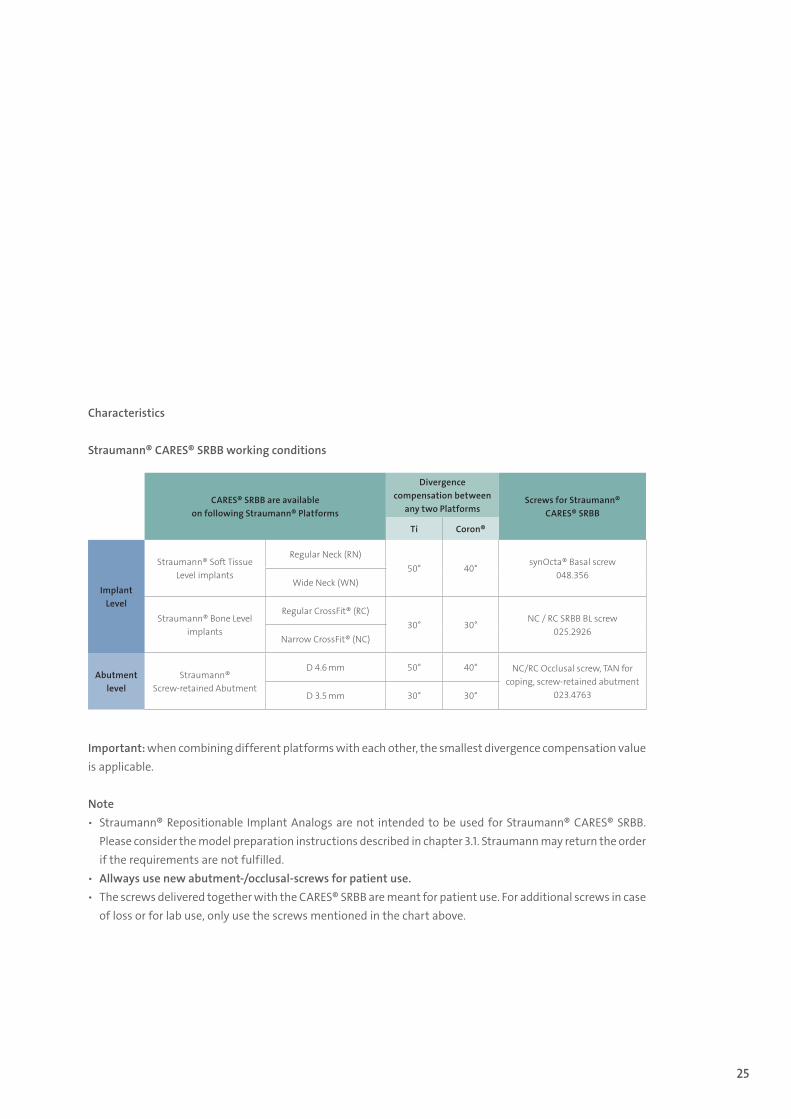
Characteristics
Straumann® CARES® SRBB working conditions
Important: when combining different platforms with each other, the smallest divergence compensation value is applicable.
Note ѹ Straumann® Repositionable Implant Analogs are not intended to be used for Straumann® CARES® SRBB.
Please consider the model preparation instructions described in chapter 3.1. Straumann may return the order if the requirements are not fulfilled.
ѹ Allways use new abutment-/occlusal-screws for patient use. ѹ The screws delivered together with the CARES® SRBB are meant for patient use. For additional screws in case
of loss or for lab use, only use the screws mentioned in the chart above.
CARES® SRBB are available on following Straumann® Platforms
Divergence compensation between
any two PlatformsScrews for Straumann®
CARES® SRBB
Ti Coron®
Implant Level
Straumann® Soft Tissue Level implants
Regular Neck (RN)50° 40°
synOcta® Basal screw048.356
Wide Neck (WN)
Straumann® Bone Level implants
Regular CrossFit® (RC)30° 30°
NC / RC SRBB BL screw025.2926
Narrow CrossFit® (NC)
Abutment level
Straumann® Screw- retained Abutment
D 4.6 mm 50° 40° NC/RC Occlusal screw, TAN for coping, screw-retained abutment
023.4763D 3.5 mm 30° 30°
15X.822_SbS_CARES.indd 25 01/12/2016 11:34
26
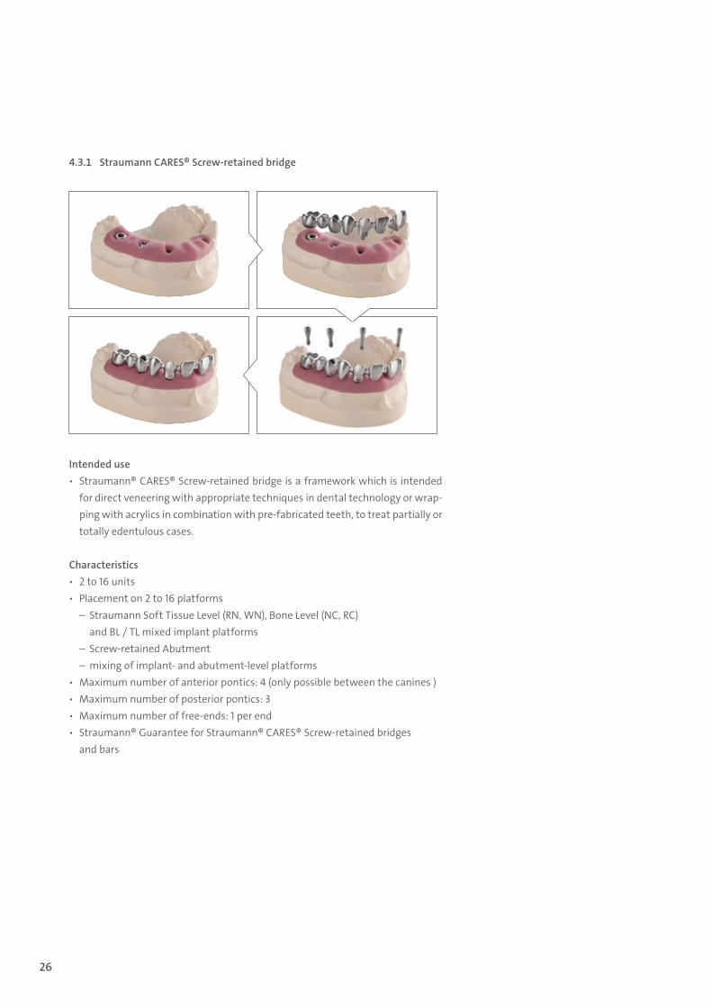
4.3.1 Straumann CARES® Screw-retained bridge
Intended use ѹ Straumann® CARES® Screw-retained bridge is a framework which is intended
for direct veneering with appropriate techniques in dental technology or wrap-ping with acrylics in combination with pre-fabricated teeth, to treat partially or totally edentulous cases.
Characteristics ѹ 2 to 16 units ѹ Placement on 2 to 16 platforms
– Straumann Soft Tissue Level (RN, WN), Bone Level (NC, RC) and BL / TL mixed implant platforms
– Screw-retained Abutment – mixing of implant- and abutment-level platforms
ѹ Maximum number of anterior pontics: 4 (only possible between the canines ) ѹ Maximum number of posterior pontics: 3 ѹ Maximum number of free-ends: 1 per end ѹ Straumann® Guarantee for Straumann® CARES® Screw-retained bridges
and bars
15X.822_SbS_CARES.indd 26 01/12/2016 11:34
27
4.3.1.1 Designing: CARES® Workflow
Step 1 – PREPARATION for CARES® VisualFollow the preparation requirements according chapter 3
Note: For optimal esthetic planning especially in the labial region, model a full anatomic wax-up and confirm the size and position intraorally. The wax-up can be scanned and used as reference when designing the restoration in CARES® Visual.
Step 2 – DESIGNING with CARES® VisualDesign the restoration according to the brochure Straumann® CARES® Visual – Step-by-step in-structions for crowns and bridges, 152.825 or watch the CARES® Tutorial videos online for further guidance.
Step 3 – ORDER PROCESS for CARES® SRBBOrder the restoration according to the process described in the brochure Straumann® CARES® Screw-retained bridge and bar: Service and Process – see p. 40.
4.3.1.2 Finishing
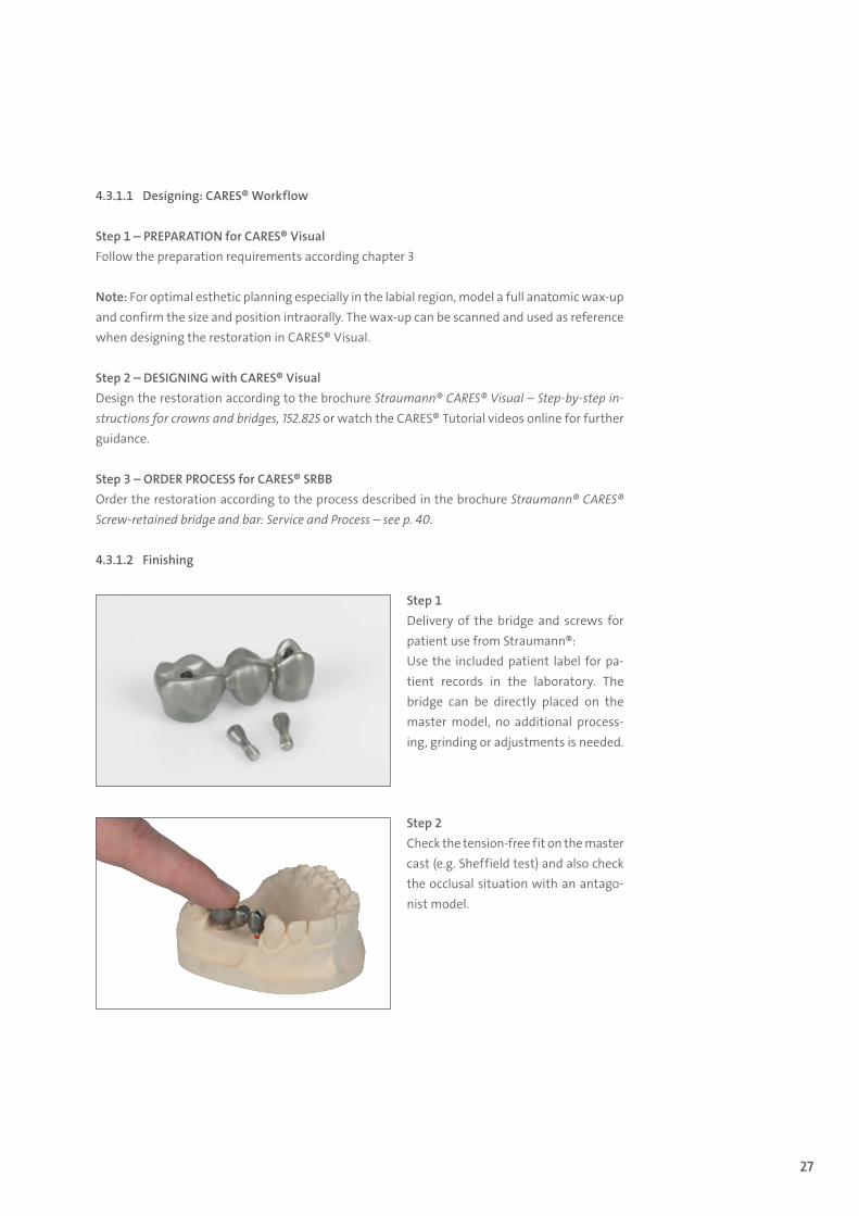
Step 1Delivery of the bridge and screws for patient use from Straumann®:Use the included patient label for pa-tient records in the laboratory. The bridge can be directly placed on the master model, no additional process-ing, grinding or adjustments is needed.
Step 2Check the tension-free fit on the master cast (e.g. Sheffield test) and also check the occlusal situation with an antago-nist model.
15X.822_SbS_CARES.indd 27 01/12/2016 11:34
28
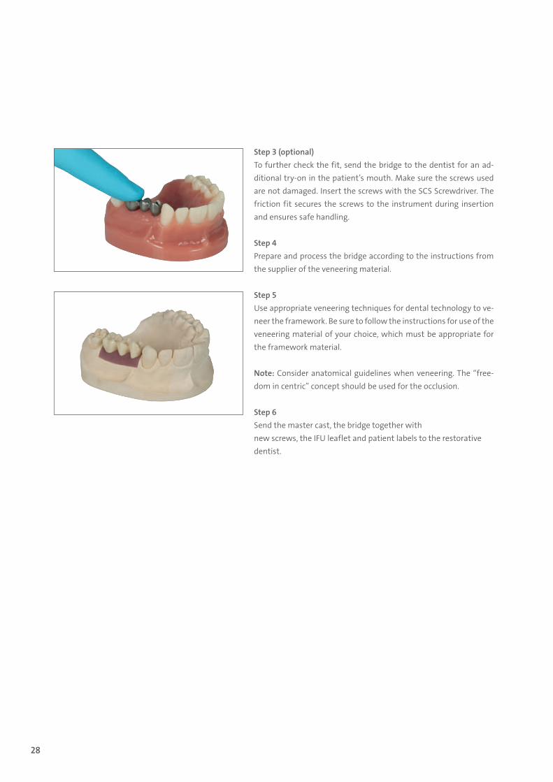
Step 3 (optional)To further check the fit, send the bridge to the dentist for an ad-ditional try-on in the patient’s mouth. Make sure the screws used are not damaged. Insert the screws with the SCS Screwdriver. The friction fit secures the screws to the instrument during insertion and ensures safe handling.
Step 4Prepare and process the bridge according to the instructions from the supplier of the veneering material.
Step 5Use appropriate veneering techniques for dental technology to ve-neer the framework. Be sure to follow the instructions for use of the veneering material of your choice, which must be appropriate for the framework material.
Note: Consider anatomical guidelines when veneering. The “free-dom in centric” concept should be used for the occlusion.
Step 6Send the master cast, the bridge together with new screws, the IFU leaflet and patient labels to the restorativedentist.
15X.822_SbS_CARES.indd 28 01/12/2016 11:34
29
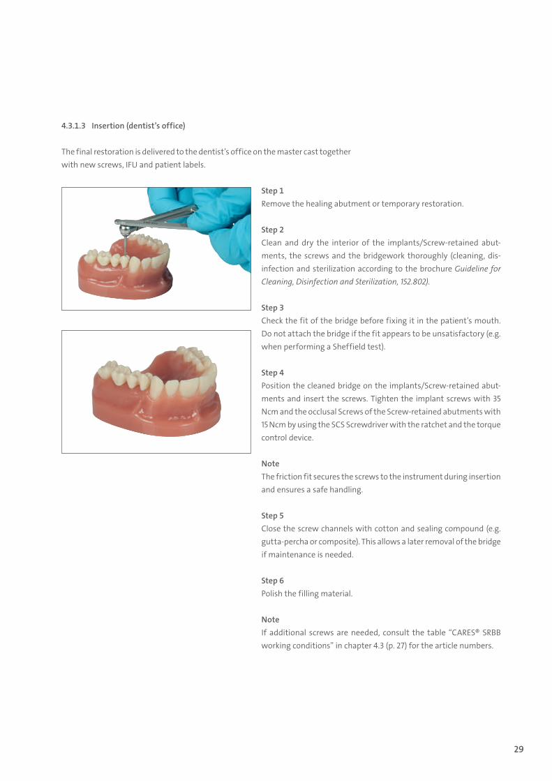
Step 1Remove the healing abutment or temporary restoration.
Step 2Clean and dry the interior of the implants/Screw-retained abut-ments, the screws and the bridgework thoroughly (cleaning, dis-infection and sterilization according to the brochure Guideline for Cleaning, Disinfection and Sterilization, 152.802).
Step 3Check the fit of the bridge before fixing it in the patient’s mouth. Do not attach the bridge if the fit appears to be unsatisfactory (e.g. when performing a Sheffield test).
Step 4Position the cleaned bridge on the implants/Screw-retained abut-ments and insert the screws. Tighten the implant screws with 35 Ncm and the occlusal Screws of the Screw-retained abutments with 15 Ncm by using the SCS Screwdriver with the ratchet and the torque control device.
NoteThe friction fit secures the screws to the instrument during insertion and ensures a safe handling.
Step 5Close the screw channels with cotton and sealing compound (e.g. gutta-percha or composite). This allows a later removal of the bridge if maintenance is needed.
Step 6Polish the filling material.
NoteIf additional screws are needed, consult the table “CARES® SRBB working conditions” in chapter 4.3 (p. 27) for the article numbers.
4.3.1.3 Insertion (dentist’s office)
The final restoration is delivered to the dentist’s office on the master cast together with new screws, IFU and patient labels.
15X.822_SbS_CARES.indd 29 01/12/2016 11:34
30
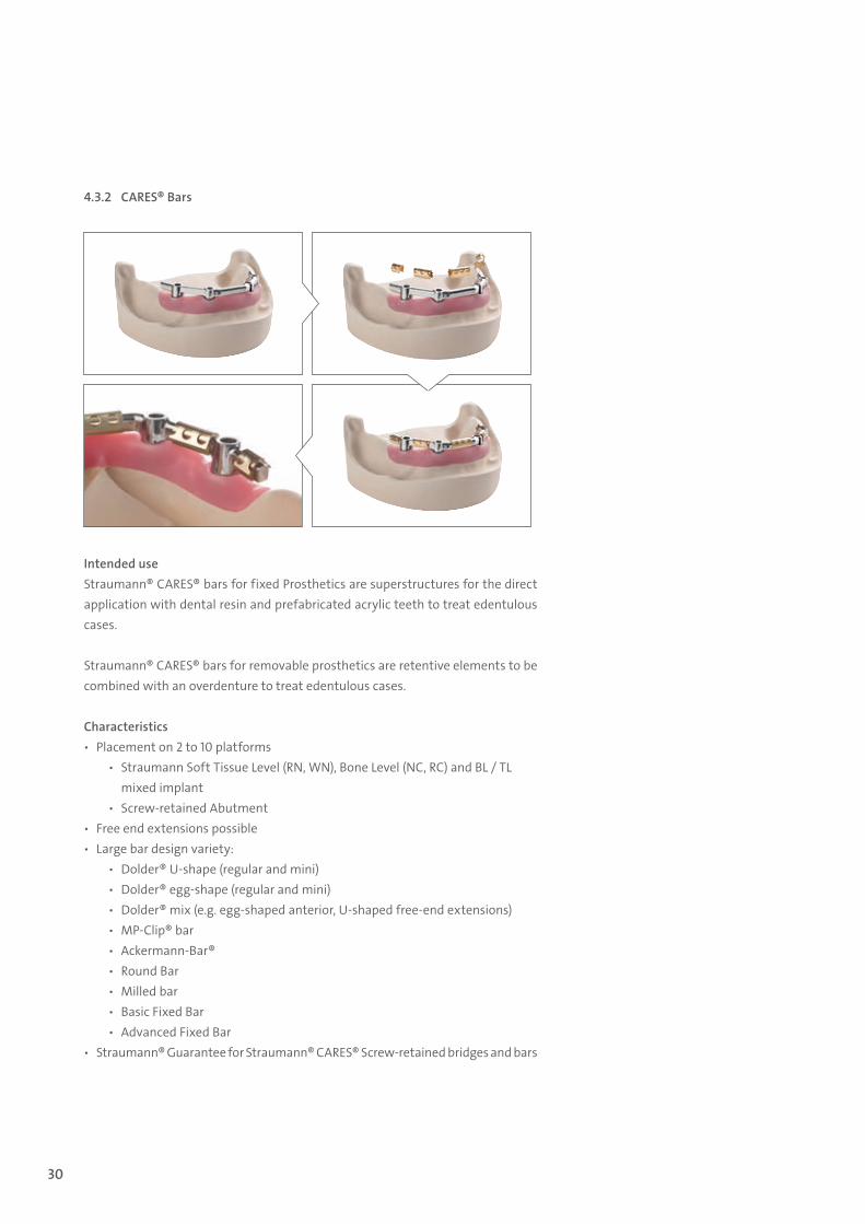
4.3.2 CARES® Bars
Intended useStraumann® CARES® bars for fixed Prosthetics are superstructures for the direct application with dental resin and prefabricated acrylic teeth to treat edentulous cases.
Straumann® CARES® bars for removable prosthetics are retentive elements to be combined with an overdenture to treat edentulous cases.
Characteristics ѹ Placement on 2 to 10 platforms
ѹ Straumann Soft Tissue Level (RN, WN), Bone Level (NC, RC) and BL / TL mixed implant
ѹ Screw-retained Abutment ѹ Free end extensions possible ѹ Large bar design variety:
ѹ Dolder® U-shape (regular and mini) ѹ Dolder® egg-shape (regular and mini) ѹ Dolder® mix (e.g. egg-shaped anterior, U-shaped free-end extensions) ѹ MP-Clip® bar ѹ Ackermann-Bar® ѹ Round Bar ѹ Milled bar ѹ Basic Fixed Bar ѹ Advanced Fixed Bar
ѹ Straumann® Guarantee for Straumann® CARES® Screw-retained bridges and bars
15X.822_SbS_CARES.indd 30 01/12/2016 11:34
31
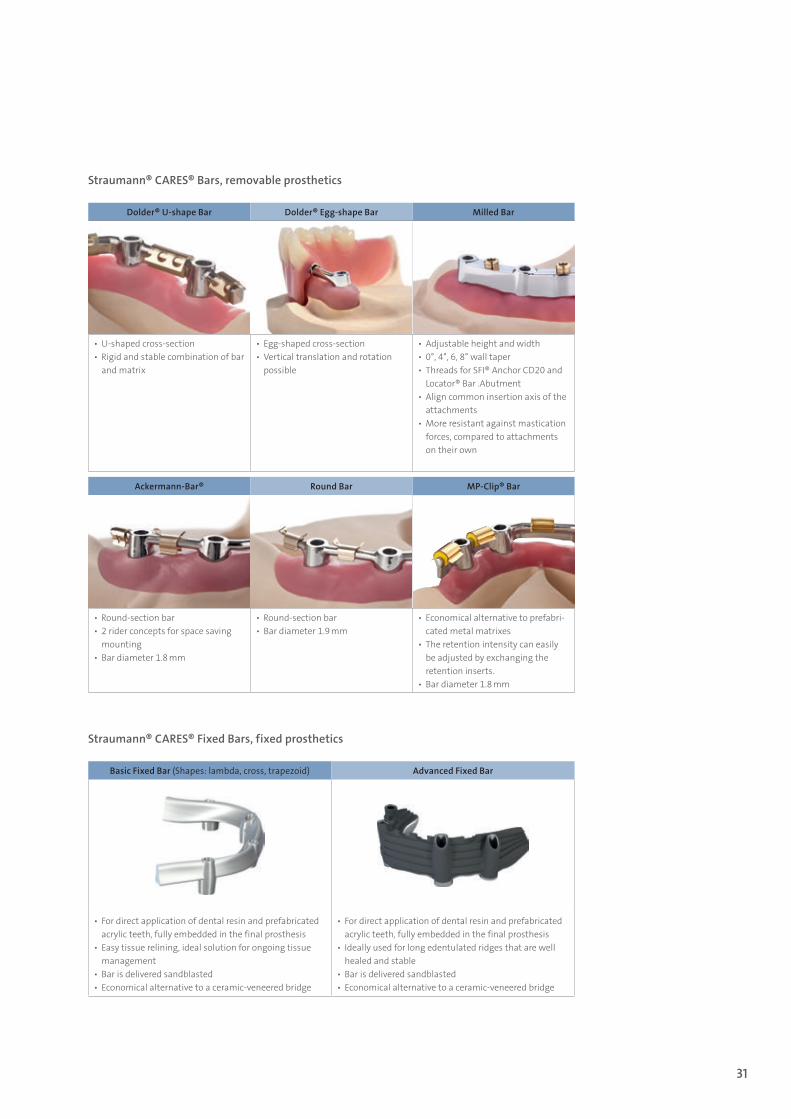
Straumann® CARES® Bars, removable prosthetics
Straumann® CARES® Fixed Bars, fixed prosthetics
Dolder® U-shape Bar Dolder® Egg-shape Bar Milled Bar
▪ U-shaped cross-section ▪ Rigid and stable combination of bar and matrix
▪ Egg-shaped cross-section ▪ Vertical translation and rotation possible
▪ Adjustable height and width ▪ 0°, 4°, 6, 8° wall taper ▪ Threads for SFI® Anchor CD20 and Locator® Bar .Abutment
▪ Align common insertion axis of the attachments
▪ More resistant against mastication forces, compared to attachments on their own
Ackermann-Bar® Round Bar MP-Clip® Bar
▪ Round-section bar ▪ 2 rider concepts for space saving mounting
▪ Bar diameter 1.8 mm
▪ Round-section bar ▪ Bar diameter 1.9 mm
▪ Economical alternative to prefabri-cated metal matrixes
▪ The retention intensity can easily be adjusted by exchanging the retention inserts.
▪ Bar diameter 1.8 mm
Basic Fixed Bar (Shapes: lambda, cross, trapezoid) Advanced Fixed Bar
▪ For direct application of dental resin and prefabricated acrylic teeth, fully embedded in the final prosthesis
▪ Easy tissue relining, ideal solution for ongoing tissue management
▪ Bar is delivered sandblasted ▪ Economical alternative to a ceramic-veneered bridge
▪ For direct application of dental resin and prefabricated acrylic teeth, fully embedded in the final prosthesis
▪ Ideally used for long edentulated ridges that are well healed and stable
▪ Bar is delivered sandblasted ▪ Economical alternative to a ceramic-veneered bridge
15X.822_SbS_CARES.indd 31 01/12/2016 11:34
32
4.3.2.1 CARES® Bars, removable prosthetics
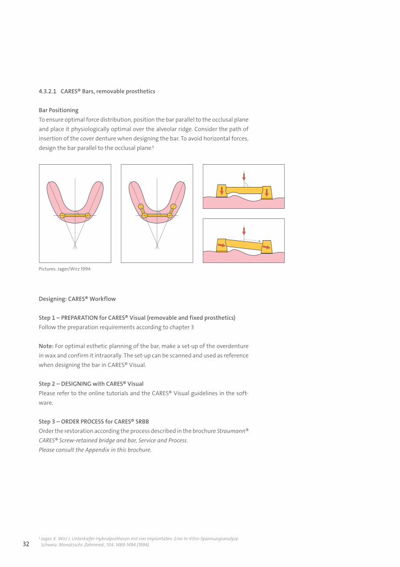
Bar Positioning To ensure optimal force distribution, position the bar parallel to the occlusal plane and place it physiologically optimal over the alveolar ridge. Consider the path of insertion of the cover denture when designing the bar. To avoid horizontal forces, design the bar parallel to the occlusal plane.1
Designing: CARES® Workflow
Step 1 – PREPARATION for CARES® Visual (removable and fixed prosthetics)Follow the preparation requirements according to chapter 3
Note: For optimal esthetic planning of the bar, make a set-up of the overdenture in wax and confirm it intraorally. The set-up can be scanned and used as reference when designing the bar in CARES® Visual.
Step 2 – DESIGNING with CARES® VisualPlease refer to the online tutorials and the CARES® Visual guidelines in the soft-ware.
Step 3 – ORDER PROCESS for CARES® SRBBOrder the restoration according the process described in the brochure Straumann® CARES® Screw-retained bridge and bar, Service and Process.Please consult the Appendix in this brochure.
1 Jager, K. Wirz J. Unterkiefer-Hybridprothesen mit vier Implantaten. Eine In-Vitro-Spannungsanalyse. Schweiz. Monatsschr. Zahnmed., 104, 1489-1494 (1994).
Pictures: Jager/Wirz 1994
15X.822_SbS_CARES.indd 32 01/12/2016 11:34
33
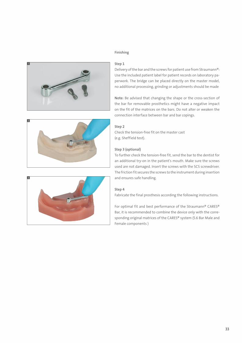
Finishing
Step 1Delivery of the bar and the screws for patient use from Straumann®: Use the included patient label for patient records on laboratory pa-perwork. The bridge can be placed directly on the master model, no additional processing, grinding or adjustments should be made
Note: Be advised that changing the shape or the cross-section of the bar for removable prosthetics might have a negative impact on the fit of the matrices on the bars. Do not alter or weaken the connection interface between bar and bar copings.
Step 2 Check the tension-free fit on the master cast (e.g. Sheffield test).
Step 3 (optional)To further check the tension-free fit, send the bar to the dentist for an additional try-on in the patient’s mouth. Make sure the screws used are not damaged. Insert the screws with the SCS screwdriver. The friction fit secures the screws to the instrument during insertion and ensures safe handling.
Step 4Fabricate the final prosthesis according the following instructions.
For optimal fit and best performance of the Straumann® CARES® Bar, it is recommended to combine the device only with the corre-sponding original matrices of the CARES® system (5.6 Bar Male and Female components )
1
2
3
15X.822_SbS_CARES.indd 33 01/12/2016 11:34
34
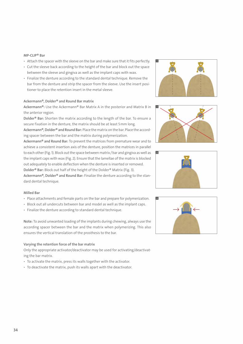
MP-CLIP® Bar ѹ Attach the spacer with the sleeve on the bar and make sure that it fits perfectly. ѹ Cut the sleeve back according to the height of the bar and block out the space
between the sleeve and gingiva as well as the implant caps with wax. ѹ Finalize the denture according to the standard dental technique. Remove the
bar from the denture and strip the spacer from the sleeve. Use the insert posi-tioner to place the retention insert in the metal sleeve.
Ackermann®, Dolder® and Round Bar matrixAckermann®: Use the Ackermann® Bar Matrix A in the posterior and Matrix B in the anterior region. Dolder® Bar: Shorten the matrix according to the length of the bar. To ensure a secure fixation in the denture, the matrix should be at least 5 mm long.Ackermann®, Dolder® and Round Bar: Place the matrix on the bar. Place the accord-ing spacer between the bar and the matrix during polymerization. Ackermann® and Round Bar: To prevent the matrices from premature wear and to achieve a consistent insertion axis of the denture, position the matrices in parallel to each other (Fig. 1). Block out the space between matrix / bar and gingiva as well as the implant caps with wax (Fig. 2). Ensure that the lamellae of the matrix is blocked out adequately to enable deflection when the denture is inserted or removed. Dolder® Bar: Block out half of the height of the Dolder® Matrix (Fig. 3).Ackermann®, Dolder® and Round Bar: Finalize the denture according to the stan-dard dental technique.
Milled Bar ѹ Place attachments and female parts on the bar and prepare for polymerization. ѹ Block out all undercuts between bar and model as well as the implant caps. ѹ Finalize the denture according to standard dental technique.
Note: To avoid unwanted loading of the implants during chewing, always use the according spacer between the bar and the matrix when polymerizing. This also ensures the vertical translation of the prosthesis to the bar.
Varying the retention force of the bar matrixOnly the appropriate activator/deactivator may be used for activating/deactivat-ing the bar matrix. ѹ To activate the matrix, press its walls together with the activator. ѹ To deactivate the matrix, push its walls apart with the deactivator.
1
1
2
3
15X.822_SbS_CARES.indd 34 01/12/2016 11:34
35
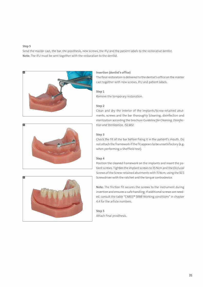
Insertion (dentist’s office)The final restoration is delivered to the dentist’s office on the master cast together with new screws, IFU and patient labels.
Step 1Remove the temporary restoration.
Step 2Clean and dry the interior of the implants/Screw-retained abut-ments, screws and the bar thoroughly (cleaning, disinfection and sterilization according the brochure Guideline for Cleaning, Disinfec-tion and Sterilization, 152.802.
Step 3Check the fit of the bar before fixing it in the patient’s mouth. Do not attach the framework if the fit appears to be unsatisfactory (e.g. when performing a Sheffield test).
Step 4Position the cleaned framework on the implants and insert the pa-tient screws. Tighten the implant screws to 35 Ncm and the Occlusal Screws of the Screw-retained abutments with 15 Ncm, using the SCS Screwdriver with the ratchet and the torque controdevice.
Note: The friction fit secures the screws to the instrument during insertion and ensures a safe handling. If additional screws are need-ed, consult the table “CARES® SRBB Working conditions” in chapter 4.4 for the article numbers.
Step 5Attach final prosthesis.
4
4
5
Step 5Send the master cast, the bar, the prosthesis, new screws, the IFU and the patient labels to the restorative dentist.Note: The IFU must be sent together with the restoration to the dentist.
15X.822_SbS_CARES.indd 35 01/12/2016 11:34
36
4.3.2.2 CARES® Fixed Bars, fixed prosthetics
This step-by-step instruction is a handling guideline for the CARES® Basic and Advanced Fixed Bars. The following steps are considered a prerequisite: ѹ The prosthetic planning has been completed and aligned between all members of the treat-
ment team ѹ A wax try-in of the prosthesis has been verified in the patient’s mouth ѹ Straumann implants have been implanted ѹ The accuracy of the master models has been counter-checked with a verification jig, to en-
sure accurate representation of the patient’s oral situation
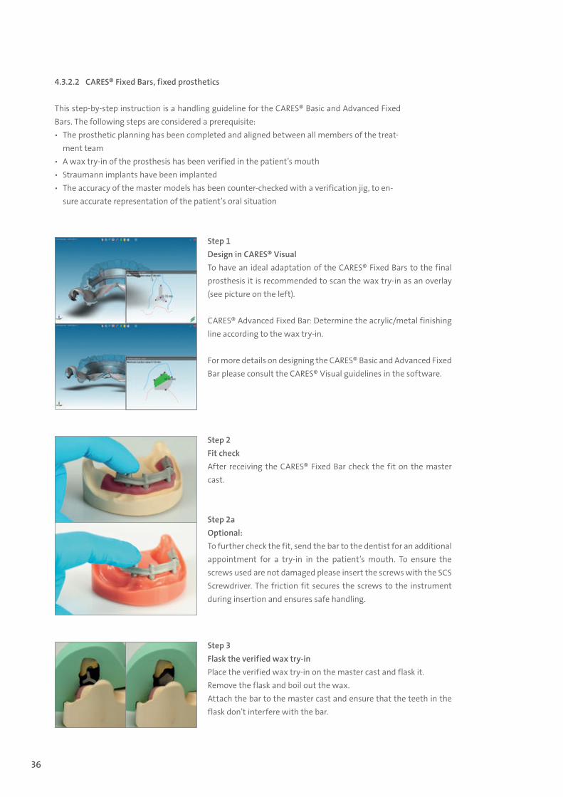
Step 1Design in CARES® VisualTo have an ideal adaptation of the CARES® Fixed Bars to the final prosthesis it is recommended to scan the wax try-in as an overlay (see picture on the left).
CARES® Advanced Fixed Bar: Determine the acrylic/metal finishing line according to the wax try-in.
For more details on designing the CARES® Basic and Advanced Fixed Bar please consult the CARES® Visual guidelines in the software.
Step 2Fit checkAfter receiving the CARES® Fixed Bar check the fit on the master cast.
Step 2aOptional:To further check the fit, send the bar to the dentist for an additional appointment for a try-in in the patient’s mouth. To ensure the screws used are not damaged please insert the screws with the SCS Screwdriver. The friction fit secures the screws to the instrument during insertion and ensures safe handling.
Step 3 Flask the verified wax try-inPlace the verified wax try-in on the master cast and flask it. Remove the flask and boil out the wax. Attach the bar to the master cast and ensure that the teeth in the flask don’t interfere with the bar.
15X.822_SbS_CARES.indd 36 01/12/2016 11:34
37
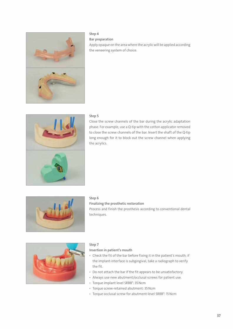
Step 4 Bar preparationApply opaque on the area where the acrylic will be applied according the veneering system of choice.
Step 5 Close the screw channels of the bar during the acrylic adaptation phase. For example, use a Q-tip with the cotton applicator removed to close the screw channels of the bar. Insert the shaft of the Q-tip long enough for it to block out the screw channel when applying the acrylics.
Step 6 Finalizing the prosthetic restorationProcess and finish the prosthesis according to conventional dental techniques.
Step 7 Insertion in patient’s mouth ѹ Check the fit of the bar before fixing it in the patient’s mouth; if
the implant-interface is subgingival, take a radiograph to verify the fit.
ѹ Do not attach the bar if the fit appears to be unsatisfactory. ѹ Always use new abutment/occlusal screws for patient use. ѹ Torque implant level SRBB*: 35 Ncm ѹ Torque screw-retained abutment: 35 Ncm ѹ Torque occlusal screw for abutment-level SRBB*: 15 Ncm
15X.822_SbS_CARES.indd 37 01/12/2016 11:34
38
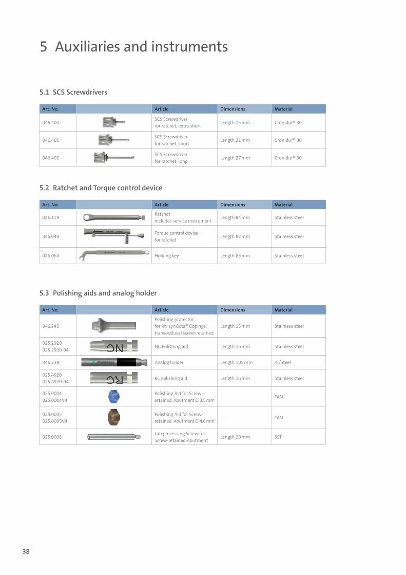
5.1 SCS Screwdrivers
5.2 Ratchet and Torque control device
5.3 Polishing aids and analog holder
Art. No. Article Dimensions Material
046.400SCS Screwdriver for ratchet, extra short
Length 15 mm Cronidur® 30
046.401SCS Screwdriver for ratchet, short
Length 21 mm Cronidur® 30
046.402SCS Screwdriver for ratchet, long
Length 27 mm Cronidur® 30
Art. No. Article Dimensions Material
046.119Ratchet includes service instrument
Length 84 mm Stainless steel
046.049Torque control devicefor ratchet
Length 82 mm Stainless steel
046.064 Holding key Length 85 mm Stainless steel
Art. No. Article Dimensions Material
046.245Polishing protector for RN synOcta® Copings, transocclusal screw-retained
Length 15 mm Stainless steel
025.2920 025.2920-04
NC Polishing aid Length 16 mm Stainless steel
046.239 Analog holder Length 105 mm Al/Steel
025.4920 025.4920-04
RC Polishing aid Length 16 mm Stainless steel
025.0004 025.0004V4
Polishing Aid for Screw- retained Abutment D 3.5 mm
– TAN
025.0005 025.0005V4
Polishing Aid for Screw- retained Abutment D 4.6 mm
– TAN
025.0006Lab processing Screw for Screw-retained Abutment
Length 20 mm SST
5 Auxiliaries and instruments
15X.822_SbS_CARES.indd 38 01/12/2016 11:34
39
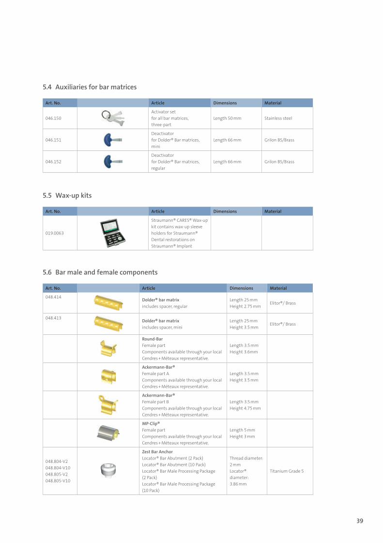
5.4 Auxiliaries for bar matrices
Art. No. Article Dimensions Material
046.150Activator set for all bar matrices, three-part
Length 50 mm Stainless steel
046.151Deactivator for Dolder® Bar matrices, mini
Length 66 mm Grilon BS/Brass
046.152Deactivator for Dolder® Bar matrices, regular
Length 66 mm Grilon BS/Brass
5.5 Wax-up kits
5.6 Bar male and female components
Art. No. Article Dimensions Material
019.0063
Straumann® CARES® Wax-up kit contains wax-up sleeve holders for Straumann® Dental restorations on Straumann® Implant
Art. No. Article Dimensions Material
048.414 Dolder® bar matrixincludes spacer, regular
Length 25 mmHeight 2.75 mm
Elitor®/ Brass
048.413 Dolder® bar matrixincludes spacer, mini
Length 25 mmHeight 3.5 mm
Elitor®/ Brass
Round-Bar Female partComponents available through your local Cendres + Méteaux representative.
Length 3.5 mmHeight 3.6mm
Ackermann-Bar®Female part AComponents available through your local Cendres + Méteaux representative.
Length 3.5 mmHeight 3.5 mm
Ackermann-Bar®Female part BComponents available through your local Cendres + Méteaux representative.
Length 3.5 mmHeight 4.75 mm
MP-Clip®Female partComponents available through your local Cendres + Méteaux representative.
Length 5 mmHeight 3 mm
048.804-V2 048.804-V10 048.805-V2 048.805-V10
Zest Bar AnchorLocator® Bar Abutment (2 Pack) Locator® Bar Abutment (10 Pack) Locator® Bar Male Processing Package (2 Pack) Locator® Bar Male Processing Package (10 Pack)
Thread diameter: 2 mmLocator® diameter: 3.86 mm
Titanium Grade 5
15X.822_SbS_CARES.indd 39 01/12/2016 11:34
40
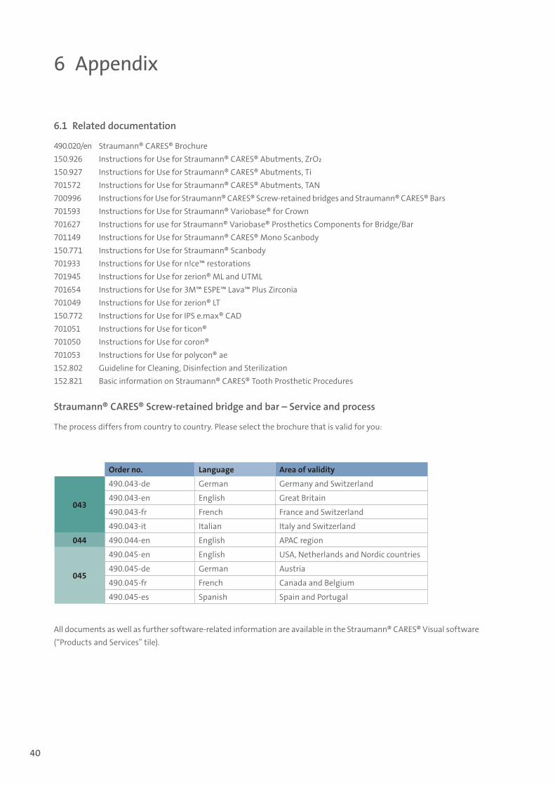
6 Appendix
6.1 Related documentation
490.020/en Straumann® CARES® Brochure150.926 Instructions for Use for Straumann® CARES® Abutments, ZrO2150.927 Instructions for Use for Straumann® CARES® Abutments, Ti701572 Instructions for Use for Straumann® CARES® Abutments, TAN700996 Instructions for Use for Straumann® CARES® Screw-retained bridges and Straumann® CARES® Bars701593 Instructions for Use for Straumann® Variobase® for Crown701627 Instructions for use for Straumann® Variobase® Prosthetics Components for Bridge/Bar701149 Instructions for Use for Straumann® CARES® Mono Scanbody150.771 Instructions for Use for Straumann® Scanbody701933 Instructions for Use for n!ce™ restorations701945 Instructions for Use for zerion® ML and UTML701654 Instructions for Use for 3M™ ESPE™ Lava™ Plus Zirconia701049 Instructions for Use for zerion® LT150.772 Instructions for Use for IPS e.max® CAD701051 Instructions for Use for ticon®701050 Instructions for Use for coron®701053 Instructions for Use for polycon® ae152.802 Guideline for Cleaning, Disinfection and Sterilization152.821 Basic information on Straumann® CARES® Tooth Prosthetic Procedures
Straumann® CARES® Screw-retained bridge and bar – Service and process
The process differs from country to country. Please select the brochure that is valid for you:
All documents as well as further software-related information are available in the Straumann® CARES® Visual software (“Products and Services” tile).
Order no. Language Area of validity
043
490.043-de German Germany and Switzerland
490.043-en English Great Britain
490.043-fr French France and Switzerland
490.043-it Italian Italy and Switzerland
044 490.044-en English APAC region
045
490.045-en English USA, Netherlands and Nordic countries
490.045-de German Austria
490.045-fr French Canada and Belgium
490.045-es Spanish Spain and Portugal
15X.822_SbS_CARES.indd 40 01/12/2016 11:34
41
7 Important guidelines
Please notePractitioners must have appropriate knowledge and instruction in the handling of the Straumann CADCAM products or other Strau-mann products (“Straumann Products”) for using the Straumann Products safely and properly in accordance with the instructions for use.
The Straumann Product must be used in accordance with the in-structions for use provided by the manufacturer. It is the practi-tioner’s responsibility to use the device in accordance with these instructions for use and to determine, if the device fits to the indi-vidual patient situation.
The Straumann Products are part of an overall concept and must be used only in conjunction with the corresponding original com-ponents and instruments distributed by Institut Straumann AG, its ultimate parent company and all affiliates or subsidiaries of such parent company (“Straumann”), except if stated otherwise in this document or in the instructions for use for the respective Strau-mann Product. If use of products made by third parties is not rec-ommended by Straumann in this document or in the respective instructions for use, any such use will void any warranty or other obligation, express or implied, of Straumann.
AvailabilitySome of the Straumann Products listed in this document may not be available in all countries.
Caution In addition to the caution notes in this document, our products must be secured against aspiration when used intraorally.
ValidityUpon publication of this document, all previous versions are super-seded.
Documentation For detailed instructions on the Straumann Products contact your Straumann representative.
Copyright and trademarksStraumann® documents may not be reprinted or published, in whole or in part, without the written authorization of Straumann. Straumann® and/or other trademarks and logos from Straumann® mentioned herein are the trademarks or registered trademarks of Straumann Holding AG and/or its affiliates.
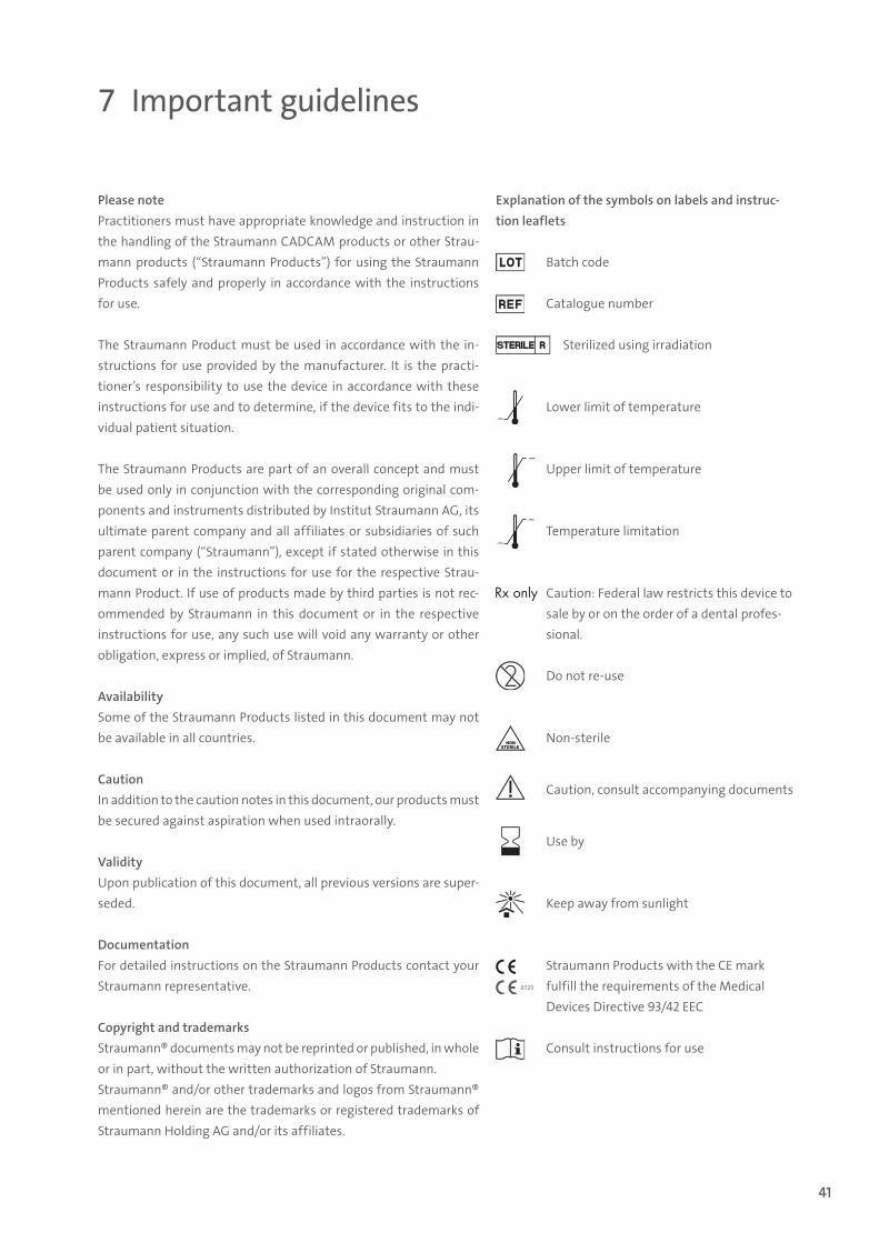
Explanation of the symbols on labels and instruc-tion leaflets
Batch code
Catalogue number
Sterilized using irradiation
…min.
Lower limit of temperature
…max.
Upper limit of temperature
…max.
…min.
Temperature limitation
Caution: Federal law restricts this device to sale by or on the order of a dental profes-sional.
Do not re-use
Non-sterile
Caution, consult accompanying documents
Use by
Keep away from sunlight
Straumann Products with the CE mark fulfill the requirements of the Medical Devices Directive 93/42 EEC
Consult instructions for use
15X.822_SbS_CARES.indd 41 01/12/2016 11:34

International Headquarters Institut Straumann AG Peter Merian-Weg 12 CH-4002 Basel, Switzerland Phone +41 (0)61 965 11 11 Fax +41 (0)61 965 11 01 www.straumann.com
Dolder® is a registered trademark from Prof. Eugen Dolder, former director of the School of Dentistry of Zürich, Switzerland.Ackermann-Bar® is a registered trademark of Cendres + Métaux Holding SA, Switzerland.MP-Clip® is a registered trademark of Cendres + Métaux Holding SA, Switzerland.IPS e.max® is a registered trademark of Ivoclar Vivadent, Liechtenstein.iTero™ is is a registered trademark of Align Technology, Inc., California.3M™ ESPE™ and Lava™ or trademarks of 3M company or 3M Deutschland GmbH. Used under license in Canada.
© Institut Straumann AG, 2016. All rights reserved.Straumann® and/or other trademarks and logos from Straumann® mentioned herein are the trademarks or registered trademarks of Straumann Holding AG and/or its affiliates. All rights reserved.
15
2.82
2/en
/D/0
0 11
/16
15X.822_SbS_CARES.indd 42 01/12/2016 11:34