Embed Size (px)
Citation preview
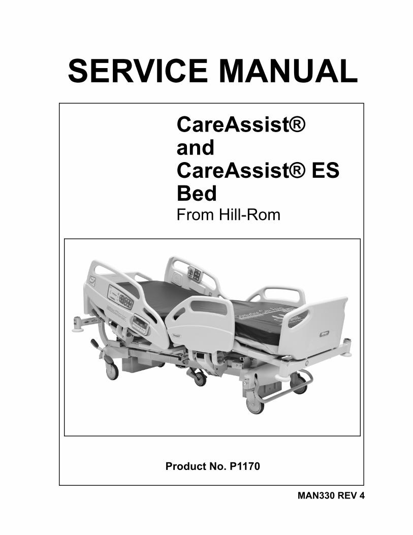
SERVICE MANUAL
CareAssist® and CareAssist® ES Bed From Hill-Rom
Product No. P1170
MAN330 REV 4

© 2009 by Hill-Rom Services, Inc. ALL RIGHTS RESERVED.
Manufactured by:
HILL-ROM 1069 STATE ROUTE 46 E BATESVILLE, IN 47006-9167
Authorized European Union Representative:
HILL-ROM SAS B.P. 14 - Z.I. DU TALHOUET 56330 PLUVIGNER FRANCE TEL: +33 (0)2 97 50 92 12
No part of this text shall be reproduced or transmitted in any form or by any means, electronic or mechanical, including photocopying, recording, or by any information or retrieval system without written permission from Hill-Rom Services, Inc. (Hill-Rom).
The information in this manual is confidential and may not be disclosed to third parties without the prior written consent of Hill-Rom.
Fourth Edition
First Printing 2003
Printed in the USA
CareAssist® is a registered trademark of Hill-Rom Services, Inc.
Comfortline® is a registered trademark of Hill-Rom Services, Inc.
CSA® is a registered trademark of Canadian Standards Association, Inc.
Dining Chair® is a trademark of Hill-Rom Services, Inc.
FullChair® is a registered trademark of Hill-Rom Services, Inc.
Hill-Rom® is a registered trademark of Hill-Rom Services, Inc.
Line-of-Site® is a registered trademark of Hill-Rom Services, Inc.
Loctite® is a registered trademark of Loctite Corporation.
NaviCare® is a registered trademark of Hill-Rom Services, Inc.
CareAssist® and CareAssist® ES Bed Service Manual (MAN330 REV 4) Page i
PLEUR-EVAC® is a registered trademark of Deknatel, Inc.
SafeView™ is a trademark of Hill-Rom Services, Inc.
SideCom® is a registered trademark of Hill-Rom Services, Inc.
Slo-Blo® is a registered trademark of Littlefuse, Inc.
Torx® is a registered trademark of Acument Intellectual Properties, LLC.
Vise-Grip® is a registered trademark of American Tool Companies, Inc.
The information contained in this manual is subject to change without notice. Hill-Rom makes no commitment to update or keep current, the information contained in this manual.
Hill-Rom reserves the right to make changes without notice in design, specifications, and models. The only warranty Hill-Rom makes is the express written warranty extended on the sale or rental of its products.
To order additional copies of this manual (MAN330), refer to the back cover for contact information. For countries not listed on the back cover, contact your distributor.
NOTE: The back cover is a comprehensive list of Technical Support contact information for Hill-Rom. The product discussed in this manual may not be available in all of the countries listed.
Revision Pages Affected Date
Original Issue December 2003 2 All January 2005 3 All May 2006 4 All March 2009
Page ii CareAssist® and CareAssist® ES Bed Service Manual (MAN330 REV 4)
Table of Contents
Chapter 1: Introduction
Purpose . . . . . . . . . . . . . . . . . . . . . . . . . . . . . . . . . . . . . . . . . . . . . . . . . . . . . . . . . . . 1-1
Audience . . . . . . . . . . . . . . . . . . . . . . . . . . . . . . . . . . . . . . . . . . . . . . . . . . . . . . . . . . 1-1
Reference Documents . . . . . . . . . . . . . . . . . . . . . . . . . . . . . . . . . . . . . . . . . . . . . . . . 1-1
Document Symbols. . . . . . . . . . . . . . . . . . . . . . . . . . . . . . . . . . . . . . . . . . . . . . . . . . 1-2
Specifications . . . . . . . . . . . . . . . . . . . . . . . . . . . . . . . . . . . . . . . . . . . . . . . . . . . . . . 1-3
Physical Description . . . . . . . . . . . . . . . . . . . . . . . . . . . . . . . . . . . . . . . . . . . . . . 1-3
Electrical Specification . . . . . . . . . . . . . . . . . . . . . . . . . . . . . . . . . . . . . . . . . . . . 1-5
Regulation, Standards, and Codes . . . . . . . . . . . . . . . . . . . . . . . . . . . . . . . . . . . 1-6
Electromagnetic Emissions and Immunity Guidance . . . . . . . . . . . . . . . . . . 1-7
Model Identification . . . . . . . . . . . . . . . . . . . . . . . . . . . . . . . . . . . . . . . . . . . . . . . . . 1-9
Safety Tips . . . . . . . . . . . . . . . . . . . . . . . . . . . . . . . . . . . . . . . . . . . . . . . . . . . . . . . 1-10
Beds with an Auxiliary Outlet . . . . . . . . . . . . . . . . . . . . . . . . . . . . . . . . . . . . . 1-12
Warning and Caution Labels . . . . . . . . . . . . . . . . . . . . . . . . . . . . . . . . . . . . . . . . . 1-13
Chapter 2: Troubleshooting Procedures
Getting Started . . . . . . . . . . . . . . . . . . . . . . . . . . . . . . . . . . . . . . . . . . . . . . . . . . . . . 2-1
Initial Actions . . . . . . . . . . . . . . . . . . . . . . . . . . . . . . . . . . . . . . . . . . . . . . . . . . . . . . 2-2
Problem/Solution Table . . . . . . . . . . . . . . . . . . . . . . . . . . . . . . . . . . . . . . . . . . . 2-2
Function Checks . . . . . . . . . . . . . . . . . . . . . . . . . . . . . . . . . . . . . . . . . . . . . . . . . . . . 2-5
Scale and Bed Exit Function Check . . . . . . . . . . . . . . . . . . . . . . . . . . . . . . . . . . . . 2-10
Final Actions. . . . . . . . . . . . . . . . . . . . . . . . . . . . . . . . . . . . . . . . . . . . . . . . . . . . . . 2-12
No Functions Work. . . . . . . . . . . . . . . . . . . . . . . . . . . . . . . . . . . . . . . . . . . . . . . . . 2-13
Lockout Malfunction . . . . . . . . . . . . . . . . . . . . . . . . . . . . . . . . . . . . . . . . . . . . . . . 2-16
Hilow Malfunction . . . . . . . . . . . . . . . . . . . . . . . . . . . . . . . . . . . . . . . . . . . . . . . . . 2-17
Knee Section Malfunction . . . . . . . . . . . . . . . . . . . . . . . . . . . . . . . . . . . . . . . . . . . 2-18
Head Section Malfunction (excluding Automatic Contour). . . . . . . . . . . . . . . . . . 2-19
Battery Backup Malfunction. . . . . . . . . . . . . . . . . . . . . . . . . . . . . . . . . . . . . . . . . . 2-20
CareAssist® and CareAssist® ES Bed Service Manual (MAN330 REV 4) Page v
Foot Section Malfunction . . . . . . . . . . . . . . . . . . . . . . . . . . . . . . . . . . . . . . . . . . . . 2-21
Trendelenburg/Reverse Trendelenburg Malfunction . . . . . . . . . . . . . . . . . . . . . . . 2-23
Bed Connected to AC Power, Brakes Not Applied Detection Malfunction . . . . . . . . . . . . . . . . . . . . . . . . . . . . . . . . . . . . . . . . . . . . . . 2-24
CPR Malfunction . . . . . . . . . . . . . . . . . . . . . . . . . . . . . . . . . . . . . . . . . . . . . . . . . . 2-27
Braking Malfunction. . . . . . . . . . . . . . . . . . . . . . . . . . . . . . . . . . . . . . . . . . . . . . . . 2-28
Steering Malfunction . . . . . . . . . . . . . . . . . . . . . . . . . . . . . . . . . . . . . . . . . . . . . . . 2-29
Scale Error 0 . . . . . . . . . . . . . . . . . . . . . . . . . . . . . . . . . . . . . . . . . . . . . . . . . . . . . . 2-30
Scale Error 1 . . . . . . . . . . . . . . . . . . . . . . . . . . . . . . . . . . . . . . . . . . . . . . . . . . . . . . 2-31
Scale Error 2 . . . . . . . . . . . . . . . . . . . . . . . . . . . . . . . . . . . . . . . . . . . . . . . . . . . . . . 2-32
Scale Error 3 . . . . . . . . . . . . . . . . . . . . . . . . . . . . . . . . . . . . . . . . . . . . . . . . . . . . . . 2-33
Scale Error 5 . . . . . . . . . . . . . . . . . . . . . . . . . . . . . . . . . . . . . . . . . . . . . . . . . . . . . . 2-34
Scale Error 0—C Model and Newer Beds . . . . . . . . . . . . . . . . . . . . . . . . . . . . . . . 2-35
Scale Error 1—C Model and Newer Beds . . . . . . . . . . . . . . . . . . . . . . . . . . . . . . . 2-36
Scale Error 2—C Model and Newer Beds . . . . . . . . . . . . . . . . . . . . . . . . . . . . . . . 2-37
Scale Error 3—C Model and Newer Beds . . . . . . . . . . . . . . . . . . . . . . . . . . . . . . . 2-38
Scale Error 4—C Model and Newer Beds . . . . . . . . . . . . . . . . . . . . . . . . . . . . . . . 2-39
Scale Error 5—C Model and Newer Beds . . . . . . . . . . . . . . . . . . . . . . . . . . . . . . . 2-40
Service Required LED Flashes—C Model and Newer Beds . . . . . . . . . . . . . . . . . 2-41
Siderail Detection Switch Malfunction—F Model Beds . . . . . . . . . . . . . . . . . . . . 2-42
Chapter 3: Theory of Operation
Introduction. . . . . . . . . . . . . . . . . . . . . . . . . . . . . . . . . . . . . . . . . . . . . . . . . . . . . . . . 3-1
Mechanical System . . . . . . . . . . . . . . . . . . . . . . . . . . . . . . . . . . . . . . . . . . . . . . . . . . 3-2
Retractable Head Section . . . . . . . . . . . . . . . . . . . . . . . . . . . . . . . . . . . . . . . . . . 3-2
Emergency CPR Release . . . . . . . . . . . . . . . . . . . . . . . . . . . . . . . . . . . . . . . . . . 3-2
Extendable Foot Section . . . . . . . . . . . . . . . . . . . . . . . . . . . . . . . . . . . . . . . . . . . 3-2
Hilow System . . . . . . . . . . . . . . . . . . . . . . . . . . . . . . . . . . . . . . . . . . . . . . . . . . . 3-2
Casters. . . . . . . . . . . . . . . . . . . . . . . . . . . . . . . . . . . . . . . . . . . . . . . . . . . . . . . . . 3-3
Braking . . . . . . . . . . . . . . . . . . . . . . . . . . . . . . . . . . . . . . . . . . . . . . . . . . . . . . . . 3-3
Steering . . . . . . . . . . . . . . . . . . . . . . . . . . . . . . . . . . . . . . . . . . . . . . . . . . . . . . . . 3-3
Head and Footboards . . . . . . . . . . . . . . . . . . . . . . . . . . . . . . . . . . . . . . . . . . . . . 3-3
Page vi CareAssist® and CareAssist® ES Bed Service Manual (MAN330 REV 4)
Electrical System (A Model Beds) . . . . . . . . . . . . . . . . . . . . . . . . . . . . . . . . . . . . . . 3-4
Power Supply Unit Characteristics . . . . . . . . . . . . . . . . . . . . . . . . . . . . . . . . . . . 3-5
Power Stage . . . . . . . . . . . . . . . . . . . . . . . . . . . . . . . . . . . . . . . . . . . . . . . . . . . . 3-5
Function Control . . . . . . . . . . . . . . . . . . . . . . . . . . . . . . . . . . . . . . . . . . . . . . . . . 3-6
Battery Circuit. . . . . . . . . . . . . . . . . . . . . . . . . . . . . . . . . . . . . . . . . . . . . . . . . . . 3-6
Battery Characteristics . . . . . . . . . . . . . . . . . . . . . . . . . . . . . . . . . . . . . . . . . 3-7
Control Logic and Specific Functions . . . . . . . . . . . . . . . . . . . . . . . . . . . . . . . . 3-7
Patient Pendant . . . . . . . . . . . . . . . . . . . . . . . . . . . . . . . . . . . . . . . . . . . . . . . . . . 3-8
Motor Characteristics . . . . . . . . . . . . . . . . . . . . . . . . . . . . . . . . . . . . . . . . . . . . . 3-8
Management of the Motors. . . . . . . . . . . . . . . . . . . . . . . . . . . . . . . . . . . . . . . . . 3-8
Detection of Bed Not in Low Position . . . . . . . . . . . . . . . . . . . . . . . . . . . . . . . . 3-9
Automatic Contour . . . . . . . . . . . . . . . . . . . . . . . . . . . . . . . . . . . . . . . . . . . . . . . 3-9
Dining Chair® Position . . . . . . . . . . . . . . . . . . . . . . . . . . . . . . . . . . . . . . . . . . . 3-9
Detection of Bed Connected to AC Power but Brakes Not Set . . . . . . . . . . . . . 3-9
Trendelenburg/Reverse Trendelenburg . . . . . . . . . . . . . . . . . . . . . . . . . . . . . . 3-10
Electrical System (B Model and Newer Beds) . . . . . . . . . . . . . . . . . . . . . . . . . . . . 3-11
Power Supply Unit Characteristics . . . . . . . . . . . . . . . . . . . . . . . . . . . . . . . . . . 3-12
Power Stage . . . . . . . . . . . . . . . . . . . . . . . . . . . . . . . . . . . . . . . . . . . . . . . . . . . 3-13
Function Control . . . . . . . . . . . . . . . . . . . . . . . . . . . . . . . . . . . . . . . . . . . . . . . . 3-13
Battery Circuit. . . . . . . . . . . . . . . . . . . . . . . . . . . . . . . . . . . . . . . . . . . . . . . . . . 3-13
Battery Characteristics . . . . . . . . . . . . . . . . . . . . . . . . . . . . . . . . . . . . . . . . 3-14
Control Logic and Specific Functions . . . . . . . . . . . . . . . . . . . . . . . . . . . . . . . 3-14
Patient Pendant . . . . . . . . . . . . . . . . . . . . . . . . . . . . . . . . . . . . . . . . . . . . . . . . . 3-15
Motor Characteristics . . . . . . . . . . . . . . . . . . . . . . . . . . . . . . . . . . . . . . . . . . . . 3-15
Management of the Motors. . . . . . . . . . . . . . . . . . . . . . . . . . . . . . . . . . . . . . . . 3-16
Detection of Bed Not in Low Position . . . . . . . . . . . . . . . . . . . . . . . . . . . . . . . 3-16
Automatic Contour . . . . . . . . . . . . . . . . . . . . . . . . . . . . . . . . . . . . . . . . . . . . . . 3-16
Dining Chair® Position . . . . . . . . . . . . . . . . . . . . . . . . . . . . . . . . . . . . . . . . . . 3-16
Detection of Bed Connected to AC Power but Brakes Not Set . . . . . . . . . . . . 3-17
Trendelenburg/Reverse Trendelenburg . . . . . . . . . . . . . . . . . . . . . . . . . . . . . . 3-17
Scale and Bed Exit Systems—B Model Beds . . . . . . . . . . . . . . . . . . . . . . . . . 3-17
CareAssist® and CareAssist® ES Bed Service Manual (MAN330 REV 4) Page vii
Scale and Bed Exit Alarm System—C Model and Newer Beds . . . . . . . . . . . 3-18
Electrical System Wiring Diagram . . . . . . . . . . . . . . . . . . . . . . . . . . . . . . . . . . . . . 3-21
Chapter 4: Removal, Replacement, and Adjustment Procedures
Tool and Supply Requirements. . . . . . . . . . . . . . . . . . . . . . . . . . . . . . . . . . . . . . . . . 4-1
Sleep Deck . . . . . . . . . . . . . . . . . . . . . . . . . . . . . . . . . . . . . . . . . . . . . . . . . . . . . . . . 4-3
AC Power Cord (A Model Beds) . . . . . . . . . . . . . . . . . . . . . . . . . . . . . . . . . . . . . . . 4-6
Power Supply (A Model Beds) . . . . . . . . . . . . . . . . . . . . . . . . . . . . . . . . . . . . . . . . . 4-9
Battery (A Model Beds) . . . . . . . . . . . . . . . . . . . . . . . . . . . . . . . . . . . . . . . . . . . . . 4-12
Head Section Motor . . . . . . . . . . . . . . . . . . . . . . . . . . . . . . . . . . . . . . . . . . . . . . . . 4-15
CPR Cable. . . . . . . . . . . . . . . . . . . . . . . . . . . . . . . . . . . . . . . . . . . . . . . . . . . . . . . . 4-20
Knee Section Motor . . . . . . . . . . . . . . . . . . . . . . . . . . . . . . . . . . . . . . . . . . . . . . . . 4-23
Foot Section Motor . . . . . . . . . . . . . . . . . . . . . . . . . . . . . . . . . . . . . . . . . . . . . . . . . 4-27
Head Hilow Column (A Model Beds) . . . . . . . . . . . . . . . . . . . . . . . . . . . . . . . . . . 4-31
Foot Hilow Column (A Model Beds) . . . . . . . . . . . . . . . . . . . . . . . . . . . . . . . . . . . 4-34
Brake Detection Switch . . . . . . . . . . . . . . . . . . . . . . . . . . . . . . . . . . . . . . . . . . . . . 4-38
Brake/Steer Bar. . . . . . . . . . . . . . . . . . . . . . . . . . . . . . . . . . . . . . . . . . . . . . . . . . . . 4-40
Caster . . . . . . . . . . . . . . . . . . . . . . . . . . . . . . . . . . . . . . . . . . . . . . . . . . . . . . . . . . . 4-44
SideCom® Communication System P.C. Board (A Model Beds) . . . . . . . . . . . . . 4-47
Interface P.C. Board (A Model Beds). . . . . . . . . . . . . . . . . . . . . . . . . . . . . . . . . . . 4-49
Fuses (A Model Beds) . . . . . . . . . . . . . . . . . . . . . . . . . . . . . . . . . . . . . . . . . . . . . . 4-51
Siderail Control P.C. Board . . . . . . . . . . . . . . . . . . . . . . . . . . . . . . . . . . . . . . . . . . 4-53
Patient Pendant . . . . . . . . . . . . . . . . . . . . . . . . . . . . . . . . . . . . . . . . . . . . . . . . . . . . 4-56
Patient Pendant Mount . . . . . . . . . . . . . . . . . . . . . . . . . . . . . . . . . . . . . . . . . . . . . . 4-57
Bed Exit Switch . . . . . . . . . . . . . . . . . . . . . . . . . . . . . . . . . . . . . . . . . . . . . . . . . . . 4-58
Head Hilow Column (B Model and Newer Beds) . . . . . . . . . . . . . . . . . . . . . . . . . 4-63
Foot Hilow Column (B Model and Newer Beds) . . . . . . . . . . . . . . . . . . . . . . . . . . 4-68
Load Beams (B Model and Newer Beds) . . . . . . . . . . . . . . . . . . . . . . . . . . . . . . . . 4-73
Scale Control Pod (B Model and Newer Beds) . . . . . . . . . . . . . . . . . . . . . . . . . . . 4-77
Scale Control Pod P.C. Board (B Model and Newer Beds) . . . . . . . . . . . . . . . . . . 4-80
Batteries (B Model and Newer Beds) . . . . . . . . . . . . . . . . . . . . . . . . . . . . . . . . . . . 4-83
Motor Control P.C. Board (B Model and Newer Beds) . . . . . . . . . . . . . . . . . . . . . 4-85
Page viii CareAssist® and CareAssist® ES Bed Service Manual (MAN330 REV 4)

SideCom® Communication System P.C. Board (B Model and Newer Beds) . . . . 4-87
Line Filter (B Model and Newer Beds) . . . . . . . . . . . . . . . . . . . . . . . . . . . . . . . . . 4-90
Scale P.C. Board (B Model and Newer Beds) . . . . . . . . . . . . . . . . . . . . . . . . . . . . 4-92
Siderail Interface P.C. Board (B Model and Newer Beds) . . . . . . . . . . . . . . . . . . . 4-94
Transformer (B Model and Newer Beds) . . . . . . . . . . . . . . . . . . . . . . . . . . . . . . . . 4-96
Power Cord (B Model and Newer Beds) . . . . . . . . . . . . . . . . . . . . . . . . . . . . . . . . 4-98
Fuses (B Model and Newer Beds) . . . . . . . . . . . . . . . . . . . . . . . . . . . . . . . . . . . . 4-101
Fifth Wheel . . . . . . . . . . . . . . . . . . . . . . . . . . . . . . . . . . . . . . . . . . . . . . . . . . . . . . 4-105
Head-End Brake/Steer Pedal . . . . . . . . . . . . . . . . . . . . . . . . . . . . . . . . . . . . . . . . 4-108
Auxiliary Outlet . . . . . . . . . . . . . . . . . . . . . . . . . . . . . . . . . . . . . . . . . . . . . . . . . . 4-110
SafeView™ Alerts . . . . . . . . . . . . . . . . . . . . . . . . . . . . . . . . . . . . . . . . . . . . . . . . 4-114
Configure the Siderails for the Safe Bed Condition . . . . . . . . . . . . . . . . . 4-119
Chapter 5: Parts List
Service Parts Ordering . . . . . . . . . . . . . . . . . . . . . . . . . . . . . . . . . . . . . . . . . . . . . . . 5-1
Exchange Policy . . . . . . . . . . . . . . . . . . . . . . . . . . . . . . . . . . . . . . . . . . . . . . . . . . . . 5-3
In-Warranty Exchanges . . . . . . . . . . . . . . . . . . . . . . . . . . . . . . . . . . . . . . . . . . . 5-3
Out-of-Warranty Exchanges . . . . . . . . . . . . . . . . . . . . . . . . . . . . . . . . . . . . . . . . 5-3
Warranty . . . . . . . . . . . . . . . . . . . . . . . . . . . . . . . . . . . . . . . . . . . . . . . . . . . . . . . . . . 5-4
Recommended Spare Parts . . . . . . . . . . . . . . . . . . . . . . . . . . . . . . . . . . . . . . . . . . . . 5-6
Base Frame—A Model Beds . . . . . . . . . . . . . . . . . . . . . . . . . . . . . . . . . . . . . . . . . 5-10
Articulating Frame—A Model Beds. . . . . . . . . . . . . . . . . . . . . . . . . . . . . . . . . . . . 5-14
Foot Extension—A Model Beds. . . . . . . . . . . . . . . . . . . . . . . . . . . . . . . . . . . . . . . 5-16
Head Siderail—A Model Beds . . . . . . . . . . . . . . . . . . . . . . . . . . . . . . . . . . . . . . . . 5-18
Foot Siderail—A Model Beds . . . . . . . . . . . . . . . . . . . . . . . . . . . . . . . . . . . . . . . . 5-22
Footboard and Headboard—A Model Beds . . . . . . . . . . . . . . . . . . . . . . . . . . . . . . 5-24
Plastic Sleep Deck—A Model Beds . . . . . . . . . . . . . . . . . . . . . . . . . . . . . . . . . . . . 5-25
Motor Control Box—A Model Beds . . . . . . . . . . . . . . . . . . . . . . . . . . . . . . . . . . . 5-26
CPR Cables—A Model Beds . . . . . . . . . . . . . . . . . . . . . . . . . . . . . . . . . . . . . . . . . 5-28
Control Cables—A Model Beds . . . . . . . . . . . . . . . . . . . . . . . . . . . . . . . . . . . . . . . 5-30
Interface Control Box—A Model Beds . . . . . . . . . . . . . . . . . . . . . . . . . . . . . . . . . 5-32
Base Frame—B and C Model Beds . . . . . . . . . . . . . . . . . . . . . . . . . . . . . . . . . . . . 5-34
CareAssist® and CareAssist® ES Bed Service Manual (MAN330 REV 4) Page ix
Articulating Frame—B Model Beds. . . . . . . . . . . . . . . . . . . . . . . . . . . . . . . . . . . . 5-38
Foot Extension—B Model Beds . . . . . . . . . . . . . . . . . . . . . . . . . . . . . . . . . . . . . . . 5-42
Head Siderail—B Model Beds . . . . . . . . . . . . . . . . . . . . . . . . . . . . . . . . . . . . . . . . 5-44
Head Siderail Mounting—B Model Beds. . . . . . . . . . . . . . . . . . . . . . . . . . . . . . . . 5-48
Foot Siderail—B Model Beds. . . . . . . . . . . . . . . . . . . . . . . . . . . . . . . . . . . . . . . . . 5-50
Footboard and Headboard—B Model Beds . . . . . . . . . . . . . . . . . . . . . . . . . . . . . . 5-52
Plastic Sleep Deck—B Model Beds . . . . . . . . . . . . . . . . . . . . . . . . . . . . . . . . . . . . 5-53
Motor Control Box—B Model Beds . . . . . . . . . . . . . . . . . . . . . . . . . . . . . . . . . . . 5-54
CPR Cables—B Model Beds . . . . . . . . . . . . . . . . . . . . . . . . . . . . . . . . . . . . . . . . . 5-56
Control Cables—B Model Beds . . . . . . . . . . . . . . . . . . . . . . . . . . . . . . . . . . . . . . . 5-58
Articulating Frame—C Model Beds. . . . . . . . . . . . . . . . . . . . . . . . . . . . . . . . . . . . 5-60
Head Siderail—C Model Beds . . . . . . . . . . . . . . . . . . . . . . . . . . . . . . . . . . . . . . . . 5-64
Motor Control Box—C Model Beds . . . . . . . . . . . . . . . . . . . . . . . . . . . . . . . . . . . 5-68
Control Cables—C Model Beds . . . . . . . . . . . . . . . . . . . . . . . . . . . . . . . . . . . . . . . 5-70
Base Frame—D Model and Newer Beds . . . . . . . . . . . . . . . . . . . . . . . . . . . . . . . . 5-72
Articulating Frame—D Model and Newer Beds . . . . . . . . . . . . . . . . . . . . . . . . . . 5-76
Foot Extension—D Model and Newer Beds . . . . . . . . . . . . . . . . . . . . . . . . . . . . . 5-80
Head Siderail—D Model and Newer Beds. . . . . . . . . . . . . . . . . . . . . . . . . . . . . . . 5-82
Head Siderail Mounting—D Model and Newer Beds . . . . . . . . . . . . . . . . . . . . . . 5-86
Foot Siderail—D Model and Newer Beds . . . . . . . . . . . . . . . . . . . . . . . . . . . . . . . 5-88
Footboard and Headboard—D Model and Newer Beds . . . . . . . . . . . . . . . . . . . . . 5-90
Plastic Sleep Deck—D Model and Newer Beds. . . . . . . . . . . . . . . . . . . . . . . . . . . 5-91
Motor Control Box—D and E Model Beds . . . . . . . . . . . . . . . . . . . . . . . . . . . . . . 5-92
CPR Cables—D Model and Newer Beds . . . . . . . . . . . . . . . . . . . . . . . . . . . . . . . . 5-95
Control Cables—D Model and Newer Beds. . . . . . . . . . . . . . . . . . . . . . . . . . . . . . 5-96
Auxiliary Outlet . . . . . . . . . . . . . . . . . . . . . . . . . . . . . . . . . . . . . . . . . . . . . . . . . . . 5-98
SafeView™ Alerts . . . . . . . . . . . . . . . . . . . . . . . . . . . . . . . . . . . . . . . . . . . . . . . . 5-100
Motor Control Box—F Model Beds . . . . . . . . . . . . . . . . . . . . . . . . . . . . . . . . . . . 5-102
Chapter 6: General Procedures
Clean and Disinfect. . . . . . . . . . . . . . . . . . . . . . . . . . . . . . . . . . . . . . . . . . . . . . . . . . 6-1
Clean . . . . . . . . . . . . . . . . . . . . . . . . . . . . . . . . . . . . . . . . . . . . . . . . . . . . . . . 6-2
Page x CareAssist® and CareAssist® ES Bed Service Manual (MAN330 REV 4)
Disinfect . . . . . . . . . . . . . . . . . . . . . . . . . . . . . . . . . . . . . . . . . . . . . . . . . . . . 6-3
Component Handling . . . . . . . . . . . . . . . . . . . . . . . . . . . . . . . . . . . . . . . . . . . . . . . . 6-4
P.C. Board. . . . . . . . . . . . . . . . . . . . . . . . . . . . . . . . . . . . . . . . . . . . . . . . . . . . . . 6-4
Lubrication Requirements. . . . . . . . . . . . . . . . . . . . . . . . . . . . . . . . . . . . . . . . . . . . . 6-5
Preventive Maintenance . . . . . . . . . . . . . . . . . . . . . . . . . . . . . . . . . . . . . . . . . . . . . . 6-6
Preventive Maintenance Schedule . . . . . . . . . . . . . . . . . . . . . . . . . . . . . . . . . . . 6-7
Preventive Maintenance Checklist . . . . . . . . . . . . . . . . . . . . . . . . . . . . . . . . . . 6-13
Scale Calibration. . . . . . . . . . . . . . . . . . . . . . . . . . . . . . . . . . . . . . . . . . . . . . . . . . . 6-14
Chapter 7: Accessories
Accessories . . . . . . . . . . . . . . . . . . . . . . . . . . . . . . . . . . . . . . . . . . . . . . . . . . . . . . . . 7-1
Infusion Support System—P158 . . . . . . . . . . . . . . . . . . . . . . . . . . . . . . . . . . . . . . . 7-2
Oxygen Tank Holder—P27601 . . . . . . . . . . . . . . . . . . . . . . . . . . . . . . . . . . . . . . . . 7-3
IV Pole—P2217 . . . . . . . . . . . . . . . . . . . . . . . . . . . . . . . . . . . . . . . . . . . . . . . . . . . . 7-4
Mattress Pad Extender—P734EA1. . . . . . . . . . . . . . . . . . . . . . . . . . . . . . . . . . . . . . 7-5
Mattress—P731EA3 . . . . . . . . . . . . . . . . . . . . . . . . . . . . . . . . . . . . . . . . . . . . . . . . . 7-6
Traction Frame Support Module—P1181B . . . . . . . . . . . . . . . . . . . . . . . . . . . . . . . 7-7
CareAssist® and CareAssist® ES Bed Service Manual (MAN330 REV 4) Page xi
NOTES:
Page xii CareAssist® and CareAssist® ES Bed Service Manual (MAN330 REV 4)
1 Chapter 1
Introduction
Purpose
This manual contains instructions for the operation and maintenance of the CareAssist® and CareAssist® ES Bed. It also includes parts lists (in chapter 5) for you to order replacement parts.
Audience
This manual is intended for use by only facility-authorized persons. To ignore this restriction could cause severe injury to people and serious damage to equipment.
Reference Documents
For more information (such as operating instructions, features, and product symbols), refer to the CareAssist® Bed and CareAssist® ES Bed User Manual (USR116).
CareAssist® and CareAssist® ES Bed Service Manual (MAN330 REV 4) Page 1 - 1
Document Symbols Chapter 1: Introduction
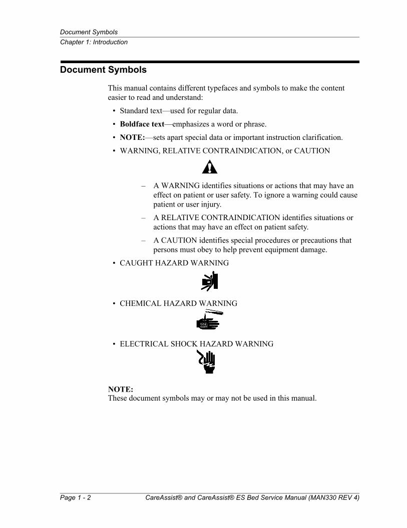
Document Symbols
This manual contains different typefaces and symbols to make the content easier to read and understand:
• Standard text—used for regular data.
• Boldface text—emphasizes a word or phrase.
• NOTE:—sets apart special data or important instruction clarification.
• WARNING, RELATIVE CONTRAINDICATION, or CAUTION
– A WARNING identifies situations or actions that may have an effect on patient or user safety. To ignore a warning could cause patient or user injury.
– A RELATIVE CONTRAINDICATION identifies situations or actions that may have an effect on patient safety.
– A CAUTION identifies special procedures or precautions that persons must obey to help prevent equipment damage.
• CAUGHT HAZARD WARNING
• CHEMICAL HAZARD WARNING
• ELECTRICAL SHOCK HAZARD WARNING
NOTE: These document symbols may or may not be used in this manual.
Page 1 - 2 CareAssist® and CareAssist® ES Bed Service Manual (MAN330 REV 4)
Specifications Chapter 1: Introduction
Specifications
Physical Description
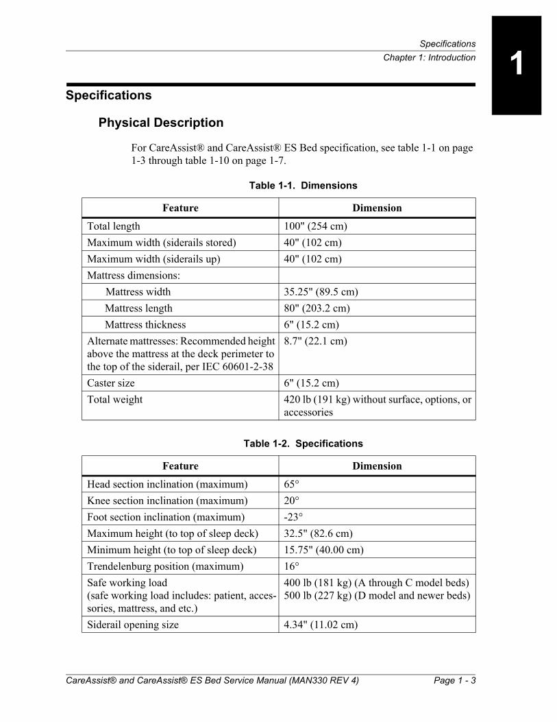
For CareAssist® and CareAssist® ES Bed specification, see table 1-1 on page 1-3 through table 1-10 on page 1-7.
Table 1-1. Dimensions
1
Feature Dimension
Total length 100" (254 cm) Maximum width (siderails stored) 40" (102 cm) Maximum width (siderails up) 40" (102 cm) Mattress dimensions:
Mattress width 35.25" (89.5 cm) Mattress length 80" (203.2 cm) Mattress thickness 6" (15.2 cm)
Alternate mattresses: Recommended height above the mattress at the deck perimeter to the top of the siderail, per IEC 60601-2-38
8.7" (22.1 cm)
Caster size 6" (15.2 cm) Total weight 420 lb (191 kg) without surface, options, or
accessories
Table 1-2. Specifications
Feature Dimension
Head section inclination (maximum) 65° Knee section inclination (maximum) 20° Foot section inclination (maximum) -23° Maximum height (to top of sleep deck) 32.5" (82.6 cm) Minimum height (to top of sleep deck) 15.75" (40.00 cm) Trendelenburg position (maximum) 16° Safe working load (safe working load includes: patient, accessories, mattress, and etc.)
400 lb (181 kg) (A through C model beds) 500 lb (227 kg) (D model and newer beds)
Siderail opening size 4.34" (11.02 cm)
CareAssist® and CareAssist® ES Bed Service Manual (MAN330 REV 4) Page 1 - 3
Specifications Chapter 1: Introduction
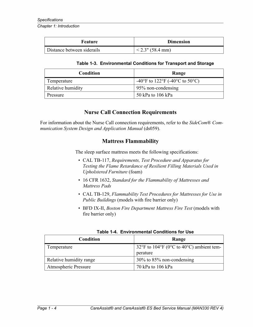
Feature Dimension
Distance between siderails < 2.3" (58.4 mm)
Table 1-3. Environmental Conditions for Transport and Storage
Condition Range Temperature -40°F to 122°F (-40°C to 50°C) Relative humidity 95% non-condensing Pressure 50 kPa to 106 kPa
Nurse Call Connection Requirements
For information about the Nurse Call connection requirements, refer to the SideCom® Communication System Design and Application Manual (ds059).
Mattress Flammability
The sleep surface mattress meets the following specifications:
• CAL TB-117, Requirements, Test Procedure and Apparatus for Testing the Flame Retardance of Resilient Filling Materials Used in Upholstered Furniture (foam)
• 16 CFR 1632, Standard for the Flammability of Mattresses and Mattress Pads
• CAL TB-129, Flammability Test Procedures for Mattresses for Use in Public Buildings (models with fire barrier only)
• BFD IX-II, Boston Fire Department Mattress Fire Test (models with fire barrier only)
Table 1-4. Environmental Conditions for Use Condition Range
Temperature 32°F to 104°F (0°C to 40°C) ambient temperature
Relative humidity range 30% to 85% non-condensing Atmospheric Pressure 70 kPa to 106 kPa
Page 1 - 4 CareAssist® and CareAssist® ES Bed Service Manual (MAN330 REV 4)
Specifications
1Chapter 1: Introduction
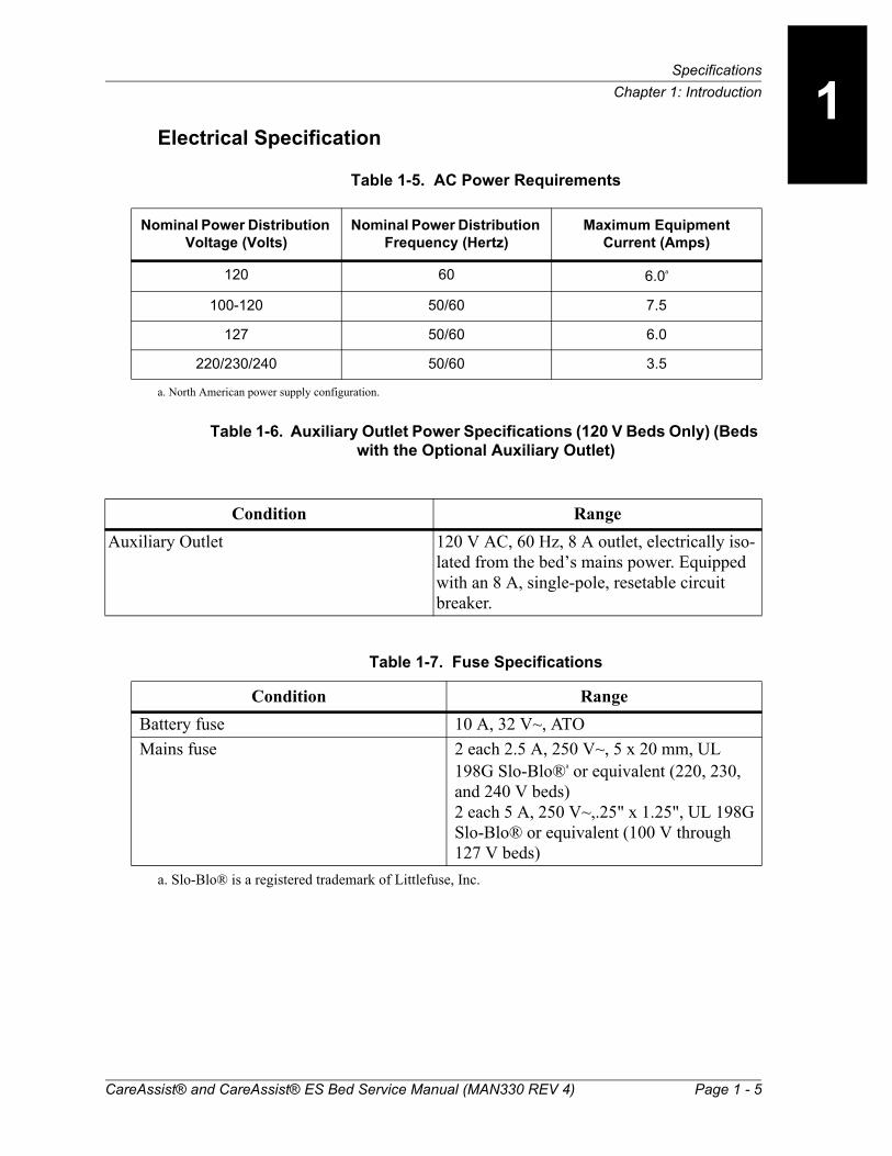
Electrical Specification
Table 1-5. AC Power Requirements
Nominal Power Distribution Voltage (Volts)
Nominal Power Distribution Frequency (Hertz)
Maximum Equipment Current (Amps)
120 60 6.0a
100-120 50/60 7.5
127 50/60 6.0
220/230/240 50/60 3.5
a. North American power supply configuration.
Table 1-6. Auxiliary Outlet Power Specifications (120 V Beds Only) (Beds with the Optional Auxiliary Outlet)
Condition Range Auxiliary Outlet 120 V AC, 60 Hz, 8 A outlet, electrically iso
lated from the bed’s mains power. Equipped with an 8 A, single-pole, resetable circuit breaker.
Table 1-7. Fuse Specifications
Condition Range Battery fuse 10 A, 32 V~, ATO Mains fuse 2 each 2.5 A, 250 V~, 5 x 20 mm, UL
198G Slo-Blo®a or equivalent (220, 230, and 240 V beds) 2 each 5 A, 250 V~,.25" x 1.25", UL 198G Slo-Blo® or equivalent (100 V through 127 V beds)
a. Slo-Blo® is a registered trademark of Littlefuse, Inc.
CareAssist® and CareAssist® ES Bed Service Manual (MAN330 REV 4) Page 1 - 5
Specifications Chapter 1: Introduction
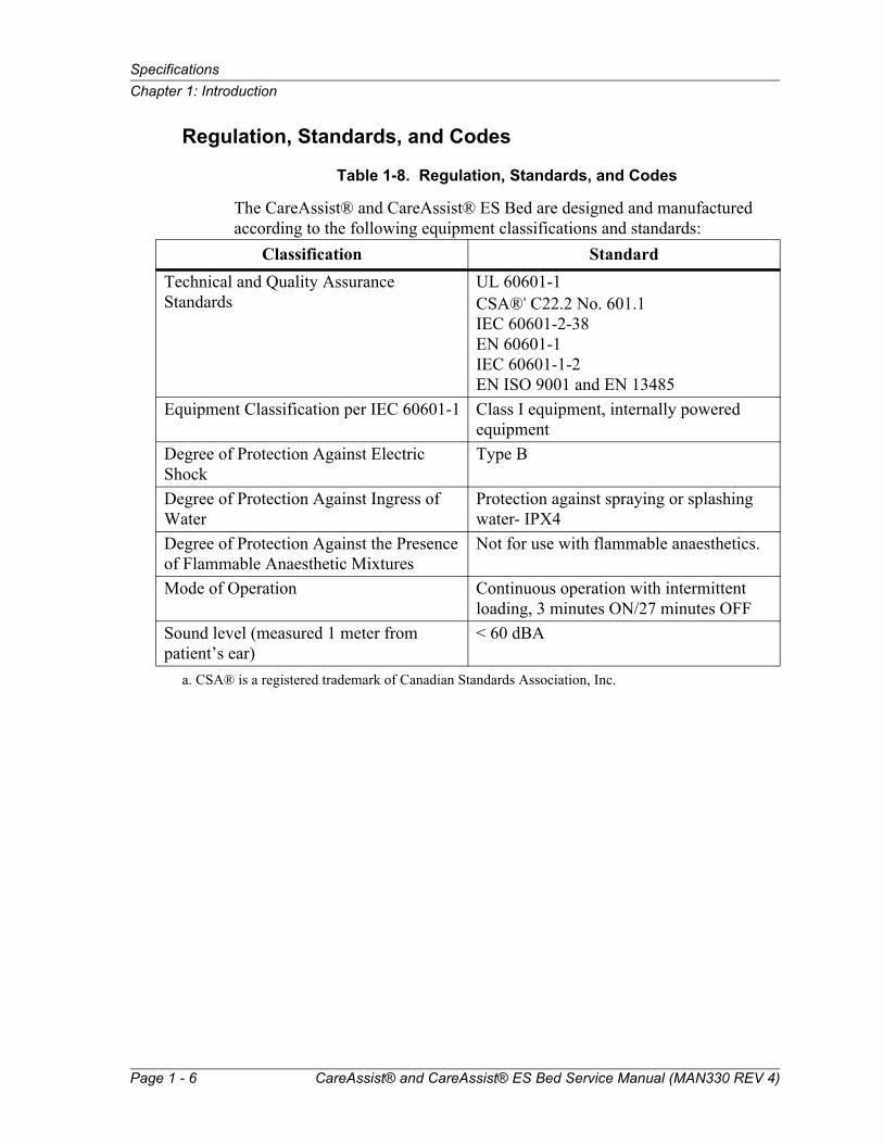
Regulation, Standards, and Codes
Table 1-8. Regulation, Standards, and Codes
The CareAssist® and CareAssist® ES Bed are designed and manufactured according to the following equipment classifications and standards:
Classification Standard Technical and Quality Assurance Standards
UL 60601-1 CSA®a C22.2 No. 601.1 IEC 60601-2-38 EN 60601-1 IEC 60601-1-2 EN ISO 9001 and EN 13485
Equipment Classification per IEC 60601-1 Class I equipment, internally powered equipment
Degree of Protection Against Electric Shock
Type B
Degree of Protection Against Ingress of Water
Protection against spraying or splashing water- IPX4
Degree of Protection Against the Presence of Flammable Anaesthetic Mixtures
Not for use with flammable anaesthetics.
Mode of Operation Continuous operation with intermittent loading, 3 minutes ON/27 minutes OFF
Sound level (measured 1 meter from patient’s ear)
< 60 dBA
a. CSA® is a registered trademark of Canadian Standards Association, Inc.
Page 1 - 6 CareAssist® and CareAssist® ES Bed Service Manual (MAN330 REV 4)
Specifications
1Chapter 1: Introduction
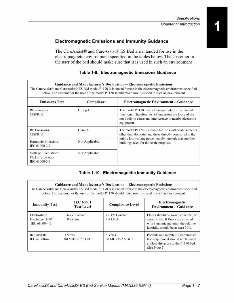
Electromagnetic Emissions and Immunity Guidance
The CareAssist® and CareAssist® ES Bed are intended for use in the electromagnetic environment specified in the tables below. The customer or the user of the bed should make sure that it is used in such an environment
Table 1-9. Electromagnetic Emissions Guidance
Guidance and Manufacturer's Declaration—Electromagnetic Emissions The CareAssist® and CareAssist® ES Bed model P1170 is intended for use in the electromagnetic environment specified
below. The customer or the user of the model P1170 should make sure it is used in such an environment.
Emissions Test Compliance Electromagnetic Environment—Guidance
RF emissions CISPR 11
Group 1 The model P1170 uses RF energy only for its internal functions. Therefore, its RF emissions are low and are not likely to cause any interference in nearby electronic equipment.
RF Emissions CISPR 11
Class A The model P1170 is suitable for use in all establishments other than domestic and those directly connected to the public low-voltage power supply network that supplies buildings used for domestic purposes. Harmonic Emissions
IEC 61000-3-2 Not Applicable
Voltage Fluctuations/ Flicker Emissions IEC 61000-3-3
Not Applicable
Table 1-10. Electromagnetic Immunity Guidance
Guidance and Manufacturer's Declaration—Electromagnetic Emissions The CareAssist® and CareAssist® ES Bed model P1170 is intended for use in the electromagnetic environment specified
below. The customer or the user of the model P1170 should make sure it is used in such an environment.
Immunity Test IEC 60601 Test Level Compliance Level Electromagnetic
Environment—Guidance
Electrostatic Discharge (ESD) IEC 61000-4-2
± 6 kV Contact ± 8 kV Air
± 6 kV Contact ± 8 kV Air
Floors should be wood, concrete, or ceramic tile. If floors are covered with synthetic material, the relative humidity should be at least 30%.
Radiated RF IEC 61000-4-3
3 Vrms 80 MHz to 2.5 GHz
3 Vrms 80 MHz to 2.5 GHz
Portable and mobile RF communications equipment should not be used at close distances to the P1170 bed. (See Note 2)
CareAssist® and CareAssist® ES Bed Service Manual (MAN330 REV 4) Page 1 - 7
Specifications Chapter 1: Introduction
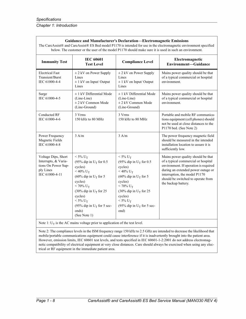
Guidance and Manufacturer's Declaration—Electromagnetic Emissions The CareAssist® and CareAssist® ES Bed model P1170 is intended for use in the electromagnetic environment specified
below. The customer or the user of the model P1170 should make sure it is used in such an environment.
Immunity Test IEC 60601 Test Level Compliance Level Electromagnetic
Environment—Guidance
Electrical Fast ± 2 kV on Power Supply ± 2 kV on Power Supply Mains power quality should be that Transient/Burst Lines Lines of a typical commercial or hospital IEC 61000-4-4 ± 1 kV on Input/ Output
Lines ± 1 kV on Input/ Output Lines
environment.
Surge ± 1 kV Differential Mode ± 1 kV Differential Mode Mains power quality should be that IEC 61000-4-5 (Line-Line)
± 2 kV Common Mode (Line-Ground)
(Line-Line) ± 2 kV Common Mode (Line-Ground)
of a typical commercial or hospital environment.
Conducted RF 3 Vrms 3 Vrms Portable and mobile RF communica-IEC 61000-4-6 150 kHz to 80 MHz 150 kHz to 80 MHz tions equipment (cell phones) should
not be used at close distances to the P1170 bed. (See Note 2)
Power Frequency 3 A/m 3 A/m The power frequency magnetic field Magnetic Fields should be measured in the intended IEC 61000-4-8 installation location to assure it is
sufficiently low.
Voltage Dips, Short < 5% UT < 5% UT Mains power quality should be that Interrupts, & Varia (95% dip in UT for 0.5 (95% dip in UT for 0.5 of a typical commercial or hospital tions On Power Sup- cycles) cycles) environment. If operation is required ply Lines < 40% UT < 40% UT
during an extended power outage or IEC 61000-4-11 (60% dip in UT for 5
cycles) < 70% UT
(60% dip in UT for 5 cycles) < 70% UT
interruption, the model P1170 should be switched to operate from the backup battery.
(30% dip in UT for 25 cycles) < 5% UT (95% dip in UT for 5 seconds) (See Note 1)
(30% dip in UT for 25 cycles) < 5% UT (95% dip in UT for 5 second)
Note 1: UT is the AC mains voltage prior to application of the test level.
Note 2: The compliance levels in the ISM frequency range 150 kHz to 2.5 GHz are intended to decrease the likelihood that mobile/portable communications equipment could cause interference if it is inadvertently brought into the patient area. However, emission limits, IEC 60601 test levels, and tests specified in IEC 60601-1-2:2001 do not address electromagnetic compatibility of electrical equipment at very close distances. Care should always be exercised when using any electrical or RF equipment in the immediate patient area.
Page 1 - 8 CareAssist® and CareAssist® ES Bed Service Manual (MAN330 REV 4)
Model Identification Chapter 1: Introduction
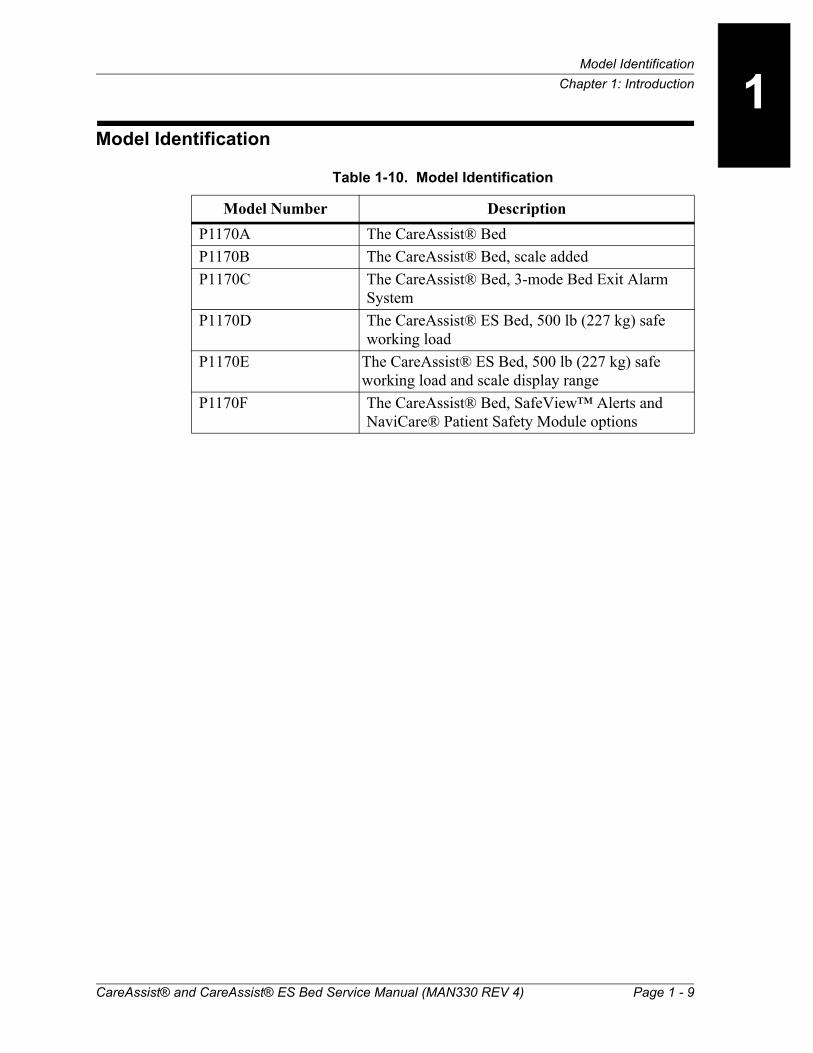
Model Identification
Table 1-10. Model Identification
1
Model Number Description P1170A The CareAssist® Bed P1170B The CareAssist® Bed, scale added P1170C The CareAssist® Bed, 3-mode Bed Exit Alarm
System P1170D The CareAssist® ES Bed, 500 lb (227 kg) safe
working load P1170E The CareAssist® ES Bed, 500 lb (227 kg) safe
working load and scale display range P1170F The CareAssist® Bed, SafeView™ Alerts and
NaviCare® Patient Safety Module options
CareAssist® and CareAssist® ES Bed Service Manual (MAN330 REV 4) Page 1 - 9
Safety Tips Chapter 1: Introduction
Safety Tips
WARNING: Only facility-authorized personnel should service the CareAssist® and CareAssist® ES Bed. Servicing performed by unauthorized personnel could cause personal injury or equipment damage.
WARNING: Obey all applicable infection control policies and procedures. Failure to do so could cause the spread of infection
WARNING: Failure to wear protective gloves may cause injury.
WARNING: Failure to wear eye protection may cause eye injury.
WARNING: Do not work under an unsupported load. Install applicable temporary supports. Failure to do so could cause personal injury or equipment damage.
SHOCK HAZARD: Failure to disconnect the unit from its power source could cause injury or equipment damage.
SHOCK HAZARD: Do not expose the unit to excessive moisture. Personal injury or equipment damage could occur.
CAUTION: Do not use harsh cleaners, solvents, or detergents. Equipment damage could occur.
Page 1 - 10 CareAssist® and CareAssist® ES Bed Service Manual (MAN330 REV 4)
Safety Tips Chapter 1: Introduction
CAUTION:
1 Do not use silicone-based lubricants. Equipment damage could occur.
CAUTION: To prevent component damage, make sure that your hands are clean, and only handle the P.C. board by its edges.
CAUTION: When handling electronic components, wear an antistatic strap. Failure to do so could cause component damage.
CAUTION: For shipping and storage, place the removed P.C. board in an antistatic protective bag. Equipment damage can occur.
CareAssist® and CareAssist® ES Bed Service Manual (MAN330 REV 4) Page 1 - 11
Safety Tips Chapter 1: Introduction
Beds with an Auxiliary Outlet
SHOCK HAZARD: This bed has two power cords. Disconnect both power cords before you service the Bed Electrical Enclosure or Auxiliary Outlet Enclosure. Only facility-authorized persons should service the Bed Electrical Enclosure or Auxiliary Outlet Enclosure. Injury or equipment damage could occur.
WARNING: The Auxiliary Outlet ground line is separate from the bed ground line. The Auxiliary Outlet does not have battery back-up. Use for non-life support medical equipment only. Failure to do so could cause injury or equipment damage.
WARNING: Do not use oxygen enriched sources near the Auxiliary Outlet. Failure to do could cause injury or equipment damage.
WARNING: Do not connect both power cords to the same wall outlet. Connect the power cords to different outlets on separate circuits. Failure to do so could cause equipment damage or the facility power breakers to turn off. Do not use the Auxiliary Outlet for life support equipment. Connect life support equipment directly into the facility power supply.
Page 1 - 12 CareAssist® and CareAssist® ES Bed Service Manual (MAN330 REV 4)
Warning and Caution Labels Chapter 1: Introduction
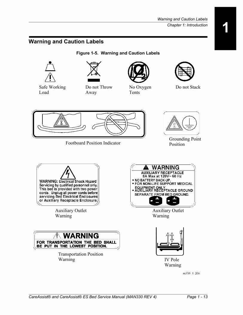
Warning and Caution Labels
Figure 1-5. Warning and Caution Labels
1
Safe Working Do not Throw No Oxygen Do not Stack Load Away Tents
Grounding PointFootboard Position Indicator Position
Auxiliary Outlet Auxiliary Outlet Warning Warning
Transportation Position Warning IV Pole
Warning
CareAssist® and CareAssist® ES Bed Service Manual (MAN330 REV 4) Page 1 - 13
Warning and Caution Labels Chapter 1: Introduction
NOTES:
Page 1 - 14 CareAssist® and CareAssist® ES Bed Service Manual (MAN330 REV 4)
Chapter 2 Troubleshooting Procedures
Getting Started
Only facility-authorized personnel should service the CareAssist® and CareAssist® ES Bed. Servicing by unauthorized personnel could result in personal injury or equipment damage.
Begin each procedure in this chapter with step 1. Follow the sequence outlined (each step assumes the previous step has been completed). In each step, the normal operation of the product can be confirmed by answering Yes or No to the statement. Your response will lead to another step in the procedure, a repair analysis procedure (RAP), or a component replacement. If more than one component is listed, replace them in the given order.
To begin gathering information about the problem, start with Initial Actions.
To isolate or identify a problem and to verify the repair after completing each corrective action (replacing or adjusting a part, seating a connector, etc.), perform the Function Checks.
To verify the repair, perform the Final Actions after the Function Checks.
If troubleshooting procedures do not isolate the problem, call Hill-Rom Technical Support at 800-445-3720 for assistance.
2
CareAssist® and CareAssist® ESBed Service Manual (MAN330 REV 4) Page 2 - 1
Initial Actions Chapter 2: Troubleshooting Procedures
Initial Actions
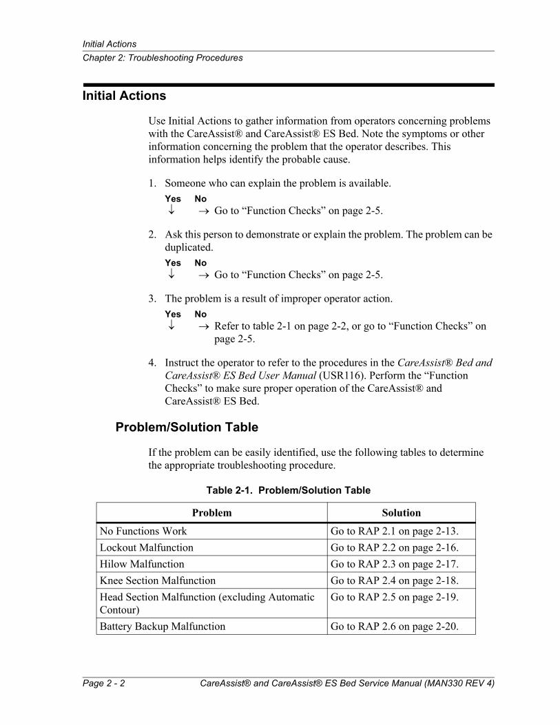
Use Initial Actions to gather information from operators concerning problems with the CareAssist® and CareAssist® ES Bed. Note the symptoms or other information concerning the problem that the operator describes. This information helps identify the probable cause.
1. Someone who can explain the problem is available. Yes No ↓ → Go to “Function Checks” on page 2-5.
2. Ask this person to demonstrate or explain the problem. The problem can be duplicated. Yes No ↓ → Go to “Function Checks” on page 2-5.
3. The problem is a result of improper operator action. Yes No ↓ → Refer to table 2-1 on page 2-2, or go to “Function Checks” on
page 2-5.
4. Instruct the operator to refer to the procedures in the CareAssist® Bed and CareAssist® ES Bed User Manual (USR116). Perform the “Function Checks” to make sure proper operation of the CareAssist® and CareAssist® ES Bed.
Problem/Solution Table
If the problem can be easily identified, use the following tables to determine the appropriate troubleshooting procedure.
Table 2-1. Problem/Solution Table
Problem Solution
No Functions Work Go to RAP 2.1 on page 2-13. Lockout Malfunction Go to RAP 2.2 on page 2-16. Hilow Malfunction Go to RAP 2.3 on page 2-17. Knee Section Malfunction Go to RAP 2.4 on page 2-18. Head Section Malfunction (excluding Automatic Contour)
Go to RAP 2.5 on page 2-19.
Battery Backup Malfunction Go to RAP 2.6 on page 2-20.
Page 2 - 2 CareAssist® and CareAssist® ES Bed Service Manual (MAN330 REV 4)
Initial Actions Chapter 2: Troubleshooting Procedures
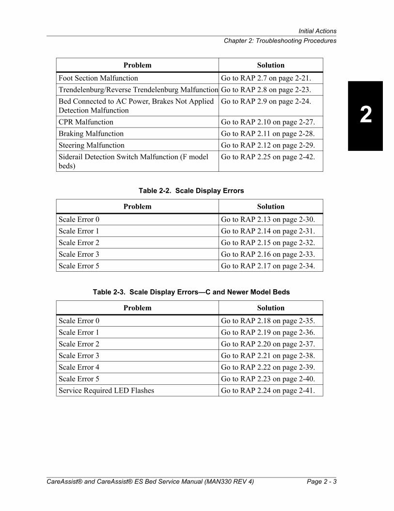
Problem Solution
Foot Section Malfunction Go to RAP 2.7 on page 2-21. Trendelenburg/Reverse Trendelenburg Malfunction Go to RAP 2.8 on page 2-23. Bed Connected to AC Power, Brakes Not Applied Detection Malfunction
Go to RAP 2.9 on page 2-24.
CPR Malfunction Go to RAP 2.10 on page 2-27. Braking Malfunction Go to RAP 2.11 on page 2-28. Steering Malfunction Go to RAP 2.12 on page 2-29. Siderail Detection Switch Malfunction (F model beds)
Go to RAP 2.25 on page 2-42.
2
Table 2-2. Scale Display Errors
Problem Solution
Scale Error 0 Go to RAP 2.13 on page 2-30. Scale Error 1 Go to RAP 2.14 on page 2-31. Scale Error 2 Go to RAP 2.15 on page 2-32. Scale Error 3 Go to RAP 2.16 on page 2-33. Scale Error 5 Go to RAP 2.17 on page 2-34.
Table 2-3. Scale Display Errors—C and Newer Model Beds
Problem Solution
Scale Error 0 Go to RAP 2.18 on page 2-35. Scale Error 1 Go to RAP 2.19 on page 2-36. Scale Error 2 Go to RAP 2.20 on page 2-37. Scale Error 3 Go to RAP 2.21 on page 2-38. Scale Error 4 Go to RAP 2.22 on page 2-39. Scale Error 5 Go to RAP 2.23 on page 2-40. Service Required LED Flashes Go to RAP 2.24 on page 2-41.
CareAssist® and CareAssist® ES Bed Service Manual (MAN330 REV 4) Page 2 - 3
Initial Actions Chapter 2: Troubleshooting Procedures
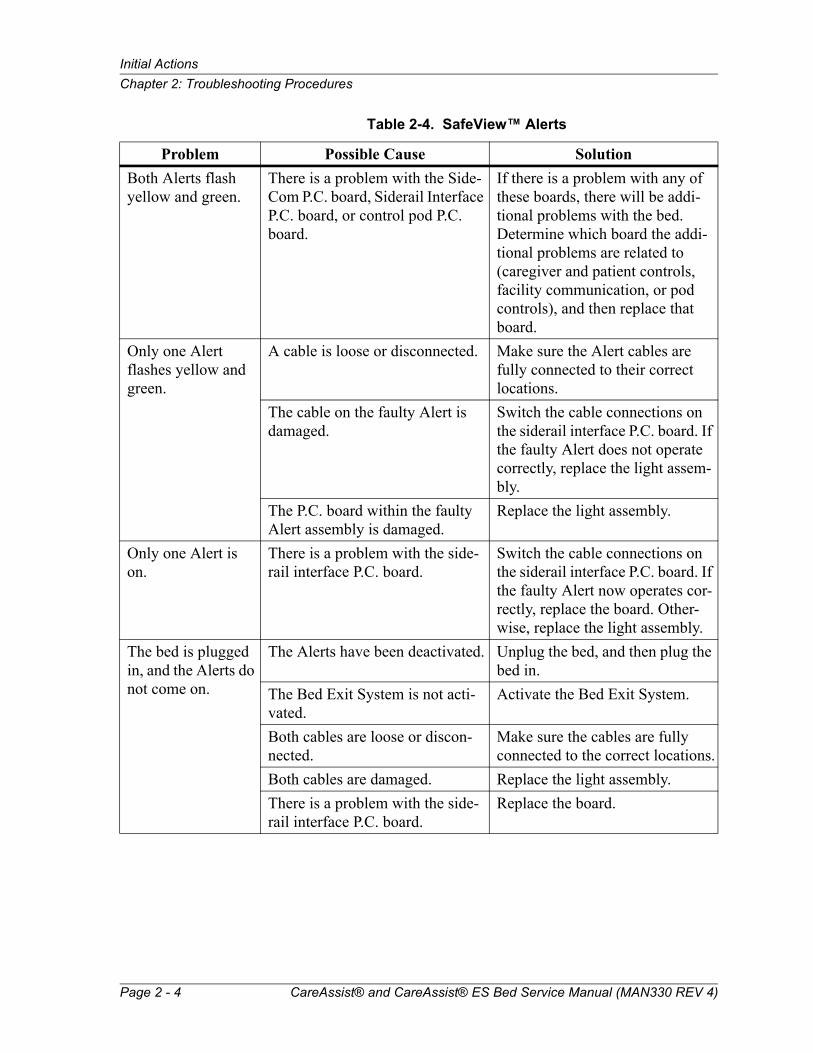
Table 2-4. SafeView™ Alerts
Problem Possible Cause Solution Both Alerts flash yellow and green.
There is a problem with the Side-Com P.C. board, Siderail Interface P.C. board, or control pod P.C. board.
If there is a problem with any of these boards, there will be additional problems with the bed. Determine which board the additional problems are related to (caregiver and patient controls, facility communication, or pod controls), and then replace that board.
Only one Alert flashes yellow and green.
A cable is loose or disconnected. Make sure the Alert cables are fully connected to their correct locations.
The cable on the faulty Alert is damaged.
Switch the cable connections on the siderail interface P.C. board. If the faulty Alert does not operate correctly, replace the light assembly.
The P.C. board within the faulty Alert assembly is damaged.
Replace the light assembly.
Only one Alert is on.
There is a problem with the side-rail interface P.C. board.
Switch the cable connections on the siderail interface P.C. board. If the faulty Alert now operates correctly, replace the board. Otherwise, replace the light assembly.
The bed is plugged in, and the Alerts do
The Alerts have been deactivated. Unplug the bed, and then plug the bed in.
not come on. The Bed Exit System is not activated.
Activate the Bed Exit System.
Both cables are loose or disconnected.
Make sure the cables are fully connected to the correct locations.
Both cables are damaged. Replace the light assembly. There is a problem with the side-rail interface P.C. board.
Replace the board.
Page 2 - 4 CareAssist® and CareAssist® ES Bed Service Manual (MAN330 REV 4)
Function Checks Chapter 2: Troubleshooting Procedures
Function Checks
1. The "Initial Actions" have been performed. Yes No ↓ → Go to “Initial Actions” on page 2-2.
2. Set the brakes, raise and lock the siderails in the high position. Plug in the power cord into an appropriate power source.
3. Operate the trendelenburg function.
This function works. Yes No ↓ → Go to RAP 2.1.
4. Lock at least one bed function (such as the head section).
The corresponding indicator is illuminated. Yes No ↓ → Go to RAP 2.2.
5. Lock out all bed functions.
All of the lock out indicators illuminate (except the Bed Not Down Indicator). Yes No ↓ → Go to RAP 2.2.
6. Unlock all of the functions.
All of the lock out indicators go off (except the Bed Not Down Indicator). Yes No ↓ → Go to RAP 2.2.
7. Press the Bed Up control.
The bed rises to the high position without stopping or an audible alarm sounding. Yes No ↓ → Go to RAP 2.3.
8. Press the Bed Down control.
The bed goes down to the low position without stopping or the audible alarm sounding. In addition, the "Bed Not Down" indicator goes off when the bed reaches the lowest position.
2
CareAssist® and CareAssist® ES Bed Service Manual (MAN330 REV 4) Page 2 - 5
Function Checks Chapter 2: Troubleshooting Procedures
Yes No ↓ → Go to RAP 2.3.
9. Press the Knee Up control.
The knee section rises to the high position without stopping or the audible alarm sounding. Yes No ↓ → Go to RAP 2.4.
10. Press the Knee Down control.
The knee section goes down to the low position without stopping or the audible alarm sounding. Yes No ↓ → Go to RAP 2.4.
11. Press the Head Up control.
The head section rises to the high position without stopping or the audible alarm sounding. Yes No ↓ → Go to RAP 2.5.
12. Press the Head Down control.
The head section goes down to the low position without stopping or the audible alarm sounding (do not consider the knee section motor). Yes No ↓ → Go to RAP 2.5.
13. Press the Head Up control. (verifying Automatic Contour)
The head section and knee section rise simultaneously, then the knee section stops at an angle approaching 17° while the head section continues to rise to its highest position. Yes No ↓ → Go to RAP 2.5.
14. Press the Head Down control.
The head section goes down, then the knee section continues to drop when the head section reaches low position. Yes No ↓ → Go to RAP 2.5.
Page 2 - 6 CareAssist® and CareAssist® ES Bed Service Manual (MAN330 REV 4)
Function Checks Chapter 2: Troubleshooting Procedures
15. Unplug the power from the power source, and test the functions checked in step 12 to step 14.
The bed functions operate properly. Yes No ↓ → Go to RAP 2.6.
16. Press the Knee Up control until it reaches the high position and then press the Foot Up control.
The foot section rises to the high position without stopping or the audible alarm sounding. Yes No ↓ → Go to RAP 2.7.
17. Press the Foot Down control.
The foot section drops to the low position without stopping or the audible alarm sounding. Yes No ↓ → Go to RAP 2.7.
18. Press the Knee Down control until knee section is in the horizontal position. Press the Dining Chair® Position control.
The head section and knee section rise until the required position is reached. Yes No ↓ → Go to RAP 2.5.
19. Press the Bed Flat control.
The head section, knee section and foot section return to the horizontal position. Yes No ↓ → Go to RAP 2.5.
20. Press the Bed Up control until the intermediate position is reached, and then operate the Trendelenburg control.
The sleep surface gradually tilts to maximum Trendelenburg without any problem or abnormal noise. Yes No ↓ → Go to RAP 2.8.
21. Press the Reverse Trendelenburg control.
2
CareAssist® and CareAssist® ES Bed Service Manual (MAN330 REV 4) Page 2 - 7
Function Checks Chapter 2: Troubleshooting Procedures
The sleep surface gradually tilts to maximum Reverse Trendelenburg without any problem or abnormal noise. Yes No ↓ → Go to RAP 2.8.
22. Plug the bed into an appropriate power source. Set the brakes to the neutral position.
An audible alarm can be heard. Yes No ↓ → Go to RAP 2.9.
23. Set the brakes.
The audible alarm stops sounding. Yes No ↓ → Go to RAP 2.9.
24. Press the Head Up control until the section reaches the high position.
NOTE: Someone should be lying on the bed so that this test can be carried out conclusively.
Pull one of the CPR control handles.
The head section descends quickly to the mid position, then slows until the horizontal position is reached. The movement occurs without any problem or abnormal noise. Repeat for the other CPR control handle. Yes No ↓ → Go to RAP 2.10.
25. Release the CPR control handle, and press the Head Up control to check that the head section motor drive mechanism is working correctly.
The head section rises without any problem or abnormal noise. Yes No ↓ → Go to RAP 2.10.
26. Try to move the bed with the brake still applied.
The four wheels are locked and prevent any movement. Yes No ↓ → Go to RAP 2.11.
27. Set the brakes to Steer, and move the bed far enough to lock the steer caster into position.
Page 2 - 8 CareAssist® and CareAssist® ES Bed Service Manual (MAN330 REV 4)
Function Checks Chapter 2: Troubleshooting Procedures
NOTE: The Brake Not Set alarm will sound.
The steer caster locks into position. Yes No ↓ → Go to RAP 2.12.
28. Go to “Final Actions” on page 2-12. 2
CareAssist® and CareAssist® ES Bed Service Manual (MAN330 REV 4) Page 2 - 9
Scale and Bed Exit Function Check Chapter 2: Troubleshooting Procedures
Scale and Bed Exit Function Check
1. Press the Weight control. Release the control pod.
The Hands Off indicator comes on. Yes No ↓ → Replace the control pod P.C. board.
2. The system beeps two times.
The weight is displayed. Yes No ↓ → Replace the control pod P.C. board.
3. Press the lb/kg control.
The lb/kg indicator toggles between lb and kg, and kg to lb. Yes No ↓ → Replace the control pod P.C. board.
4. Put 50 lb (23 kg) on the center of the bed. Press the Zero control.
Weight display shows 0.0. Yes No ↓ → Replace scale P.C. board.
5. Remove the weight. Press the Zero control.
Weight display shows 0.0. Yes No ↓ → Replace the scale P.C. board.
6. Press the Enable control on the control pod.
The Enable indicator comes on. Yes No ↓ → Replace the control pod P.C. board.
7. Press the Tone control on the control pod.
The tone sounds. Yes No ↓ → Replace the control pod P.C. board.
8. Put 50 lb (23 kg) on the bed.
Page 2 - 10 CareAssist® and CareAssist® ES Bed Service Manual (MAN330 REV 4)
Scale and Bed Exit Function Check Chapter 2: Troubleshooting Procedures
9. Press the Bed Exit control.
The Bed Exit indicators come on. Yes No ↓ → Replace the scale P.C. board.
10. Remove the weight.
The alarm sounds. Yes No ↓ → Replace the scale P.C. board.
11. Press the Bed Exit Alarm control.
The alarm goes off and the indicators go off. Yes No ↓ → Replace the scale P.C. board.
12. Go to “Final Actions” on page 2-12.
2
CareAssist® and CareAssist® ES Bed Service Manual (MAN330 REV 4) Page 2 - 11
Chapter 2: Troubleshooting Procedures
Final Actions
1. Perform the required preventive maintenance procedures. See “Preventive Maintenance” on page 6-6.
2. Complete all required administrative tasks.
Page 2 - 12 CareAssist® and CareAssist® ES Bed Service Manual (MAN330 REV 4)
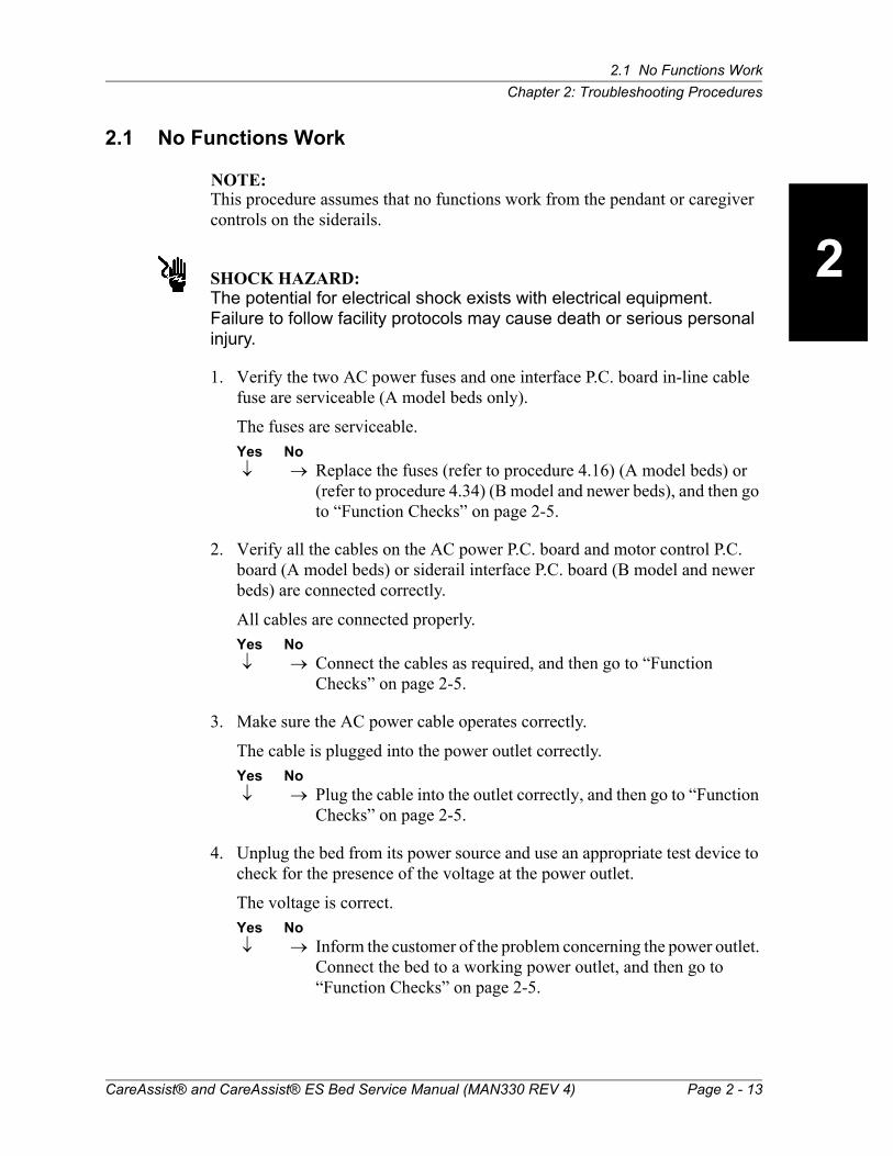
2.1 No Functions Work Chapter 2: Troubleshooting Procedures
2.1 No Functions Work
NOTE: This procedure assumes that no functions work from the pendant or caregiver controls on the siderails.
SHOCK HAZARD: The potential for electrical shock exists with electrical equipment. Failure to follow facility protocols may cause death or serious personal injury.
1. Verify the two AC power fuses and one interface P.C. board in-line cable fuse are serviceable (A model beds only).
The fuses are serviceable. Yes No ↓ → Replace the fuses (refer to procedure 4.16) (A model beds) or
(refer to procedure 4.34) (B model and newer beds), and then go to “Function Checks” on page 2-5.
2. Verify all the cables on the AC power P.C. board and motor control P.C. board (A model beds) or siderail interface P.C. board (B model and newer beds) are connected correctly.
All cables are connected properly. Yes No ↓ → Connect the cables as required, and then go to “Function
Checks” on page 2-5.
3. Make sure the AC power cable operates correctly.
The cable is plugged into the power outlet correctly. Yes No ↓ → Plug the cable into the outlet correctly, and then go to “Function
Checks” on page 2-5.
4. Unplug the bed from its power source and use an appropriate test device to check for the presence of the voltage at the power outlet.
The voltage is correct. Yes No ↓ → Inform the customer of the problem concerning the power outlet.
Connect the bed to a working power outlet, and then go to “Function Checks” on page 2-5.
2
CareAssist® and CareAssist® ES Bed Service Manual (MAN330 REV 4) Page 2 - 13
2.1 No Functions Work Chapter 2: Troubleshooting Procedures
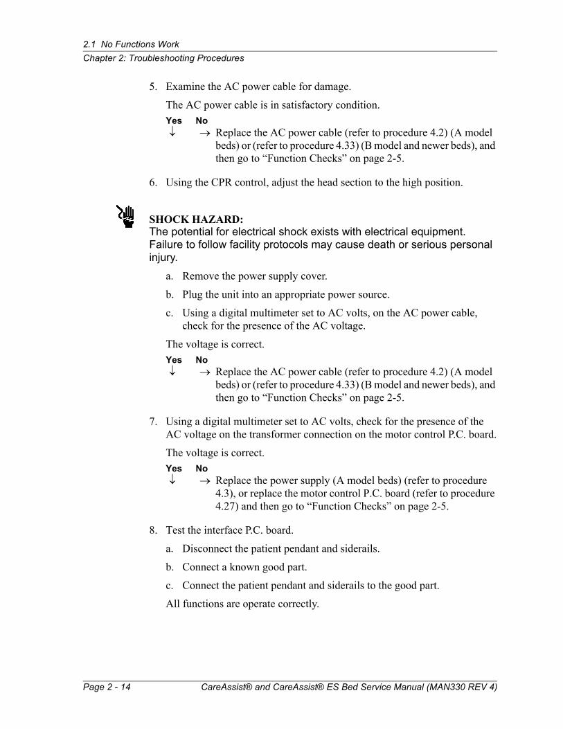
5. Examine the AC power cable for damage.
The AC power cable is in satisfactory condition. Yes No ↓ → Replace the AC power cable (refer to procedure 4.2) (A model
beds) or (refer to procedure 4.33) (B model and newer beds), and then go to “Function Checks” on page 2-5.
6. Using the CPR control, adjust the head section to the high position.
SHOCK HAZARD: The potential for electrical shock exists with electrical equipment. Failure to follow facility protocols may cause death or serious personal injury.
a. Remove the power supply cover.
b. Plug the unit into an appropriate power source.
c. Using a digital multimeter set to AC volts, on the AC power cable, check for the presence of the AC voltage.
The voltage is correct. Yes No ↓ → Replace the AC power cable (refer to procedure 4.2) (A model
beds) or (refer to procedure 4.33) (B model and newer beds), and then go to “Function Checks” on page 2-5.
7. Using a digital multimeter set to AC volts, check for the presence of the AC voltage on the transformer connection on the motor control P.C. board.
The voltage is correct. Yes No ↓ → Replace the power supply (A model beds) (refer to procedure
4.3), or replace the motor control P.C. board (refer to procedure 4.27) and then go to “Function Checks” on page 2-5.
8. Test the interface P.C. board.
a. Disconnect the patient pendant and siderails.
b. Connect a known good part.
c. Connect the patient pendant and siderails to the good part.
All functions are operate correctly.
Page 2 - 14 CareAssist® and CareAssist® ES Bed Service Manual (MAN330 REV 4)
2.1 No Functions Work Chapter 2: Troubleshooting Procedures
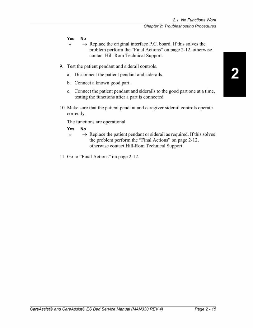
Yes ↓
No → Replace the original interface P.C. board. If this solves the
problem perform the “Final Actions” on page 2-12, otherwise contact Hill-Rom Technical Support.
9. Test the patient pendant and siderail controls.
a. Disconnect the patient pendant and siderails.
b. Connect a known good part.
c. Connect the patient pendant and siderails to the good part one at a time, testing the functions after a part is connected.
10. Make sure that the patient pendant and caregiver siderail controls operate correctly.
The functions are operational. Yes No ↓ → Replace the patient pendant or siderail as required. If this solves
the problem perform the “Final Actions” on page 2-12, otherwise contact Hill-Rom Technical Support.
11. Go to “Final Actions” on page 2-12.
2
CareAssist® and CareAssist® ES Bed Service Manual (MAN330 REV 4) Page 2 - 15
2.2 Lockout Malfunction Chapter 2: Troubleshooting Procedures
2.2 Lockout Malfunction
NOTE: The symptom of this fault is after pressing the lockout button, none of the indicators flash.
NOTE: The Bed Not Down indicator does not flash in the steps that include the asterisk symbol (*).
1. At least one of the other functions operate correctly. Yes No ↓ → Go to RAP 2.1.
2. Verify the correct connection in the interface box:
a. Swap siderail cable connections inside the interface box (A model beds) or inside the power supply (B model and newer beds).
b. Press the Lockout control.
All the indicators flash (*). Yes No ↓ → Go to step 4.
3. Replace the siderail interface P.C. board (refer to procedure 4.15) (A model beds) or (refer to procedure 4.31) (B model and newer beds) on the affected siderail.
4. Do the following to make sure the caregiver siderail controls operate properly:
a. Disconnect the control unit.
b. Connect a known good part.
c. Press the function on the caregiver control panel.
All the LEDs flash (*). Yes No ↓ → Replace the siderail control panel (refer to procedure 4.17 on
page 4-53) with the proper configuration. If this solves the problem perform the “Final Actions” on page 2-12, otherwise contact Hill-Rom Technical Support.
5. Go to “Final Actions” on page 2-12.
Page 2 - 16 CareAssist® and CareAssist® ES Bed Service Manual (MAN330 REV 4)
2.3 Hilow Malfunction Chapter 2: Troubleshooting Procedures
2.3 Hilow Malfunction
1. At least one of the other functions is working. Yes No ↓ → Go to RAP 2.1.
2. Identify the relevant hilow column.
One hilow column does not operate. Yes No ↓ → Go to step 5.
3. Swap the hilow column connectors #6 and #4 (yellow) on the power supply P.C. board (see table 4-1 on page 4-11).
The faulty column operates properly. Yes No ↓ → Replace the defective column: head hilow (refer to procedure 4.9
on page 4-31) or foot hilow (refer to procedure 4.21 on page 4-63).
4. Replace the power supply (refer to procedure 4.3 on page 4-9) or motor control P.C board (B model and newer beds) (refer to procedure 4.27 on page 4-85).
5. Go to “Final Actions” on page 2-12.
2
CareAssist® and CareAssist® ES Bed Service Manual (MAN330 REV 4) Page 2 - 17
2.4 Knee Section Malfunction Chapter 2: Troubleshooting Procedures
2.4 Knee Section Malfunction
1. At least one of the other functions operates correctly. Yes No ↓ → Go to RAP 2.1.
2. Do the following to make sure the controls operate correctly.
a. Connect a known good part.
The controls operate correctly. Yes No ↓ → Go to step 4.
3. Replace the affected control.
4. Do the following to make sure knee section motor operates correctly.
a. Remove the power supply cover.
b. Swap the knee section and foot section motor connectors (#5 brown & #2 green) or connect a new knee section motor.
c. Press the Foot Up/Down control to raise and lower the knee section.
5. The knee section operates correctly. Yes No ↓ → Replace the knee motor (refer to procedure 4.7 on page 4-23). If
this solves the problem perform the “Final Actions” on page 2-12, otherwise contact Hill-Rom Technical Support.
6. Replace the power supply (A model beds) (refer to procedure 4.3 on page 4-9) or motor control P.C board (B model and newer beds) (refer to procedure 4.27 on page 4-85).
This solves the problem. Yes No ↓ → Contact Hill-Rom technical support.
7. Go to “Final Actions” on page 2-12.
Page 2 - 18 CareAssist® and CareAssist® ES Bed Service Manual (MAN330 REV 4)
2.5 Head Section Malfunction (excluding Automatic Contour) Chapter 2: Troubleshooting Procedures
2.5 Head Section Malfunction (excluding Automatic Contour)
1. At least one of the other functions is working. Yes No ↓ → Go to RAP 2.1.
2. Do the following to make sure controls operate correctly.
a. Connect a known good part.
The functions are operating correctly. Yes No ↓ → Go to step 4.
3. Replace the affected control.
4. Do the following to make sure head section motor operates correctly.
a. Press the Head Up control and raise the head section to the high position. If this cannot be accomplished electrically, use the CPR handle and raise the head section manually.
b. Remove the power supply cover.
c. Connect a known good motor.
d. Press the Head Up control to “raise” then press the Head Down control to “lower” the head section.
The head section operates correctly. Yes No ↓ → Replace the head motor (refer to procedure 4.5 on page 4-15). If
this solves the problem perform the “Final Actions” on page 2-12, otherwise contact Hill-Rom technical support.
5. Replace the power supply (refer to procedure 4.3 on page 4-9).
This solves the problem. Yes No ↓ → Contact Hill-Rom technical support.
6. Go to “Final Actions” on page 2-12.
2
CareAssist® and CareAssist® ES Bed Service Manual (MAN330 REV 4) Page 2 - 19
2.6 Battery Backup Malfunction Chapter 2: Troubleshooting Procedures
2.6 Battery Backup Malfunction
1. Inspect the date on the battery. Replace if older than 3 years old.
2. Do the following to make sure the controls operate correctly.
a. Connect a known good control (pendant or siderail P.C. board).
The controls operate correctly. Yes No ↓ → Go to step 4.
3. Replace the affected controls.
4. Remove the power supply cover (A model beds), or battery cover (B model and newer beds), and make sure the batteries are properly connected.
The battery is connected properly. Yes No ↓ → Connect the battery properly and go to “Function Checks” on
page 2-5.
5. Make sure the battery is charging properly.
Plug the bed into an appropriate power source, and make sure that it remains connected for at least 12 hours without the batteries being used. After 12 hours, unplug the bed from its power source.
The bed operates correctly on battery backup after charging. Yes No ↓ → Go to step 7.
6. Go to “Final Actions” on page 2-12.
7. Make sure the battery backup is not defective by replacing with a new battery.
The bed operates correctly with the new battery backup. Yes No ↓ → Contact Hill-Rom Technical Support.
8. Replace the power supply (A model beds) (refer to procedure 4.3) or the motor control P.C. board (B model and newer beds) (refer to procedure 4.27). If this solves the problem perform the “Final Actions” on page 2-12, otherwise contact Hill-Rom Technical Support.
Page 2 - 20 CareAssist® and CareAssist® ES Bed Service Manual (MAN330 REV 4)
2.7 Foot Section Malfunction Chapter 2: Troubleshooting Procedures
2.7 Foot Section Malfunction
1. At least one of the other functions is working. Yes No ↓ → Go to RAP 2.1.
2. Do the following to make sure the controls operate correctly.
a. Disconnect all the controls.
b. Connect connect a known good control.
3. The controls operate correctly. Yes No ↓ → Go to step 5.
4. Connect one control at a time until the bad control is located. Replace the affected control.
5. Test the function of the foot section motor intermediate switch.
The problem only occurs with the Dining Chair® Position and knee section functions. Yes No ↓ → Go to step 7.
6. Go to step 11.
7. Do the following:
a. Remove the power supply cover.
b. Swap the connectors of the knee section and foot section motors (#5 brown, #2 green) on the power board.
c. Activate the CPR function.
The foot section function operates correctly, the knee section motor rod extends to mid-travel. Yes No ↓ → Replace the foot motor (refer to procedure 4.8 on page 4-27).
8. Test the function of the thigh section motor intermediate switch.
a. Connect the foot section motor cable to its socket (#2, green).
b. Either connect a new thigh section motor in extended position or using an ohmmeter, check the state of the intermediate switch of the thigh section motor. The motor is extended, the contacts 3 and 4 of the 4-pin
2
CareAssist® and CareAssist® ES Bed Service Manual (MAN330 REV 4) Page 2 - 21
2.7 Foot Section Malfunction Chapter 2: Troubleshooting Procedures
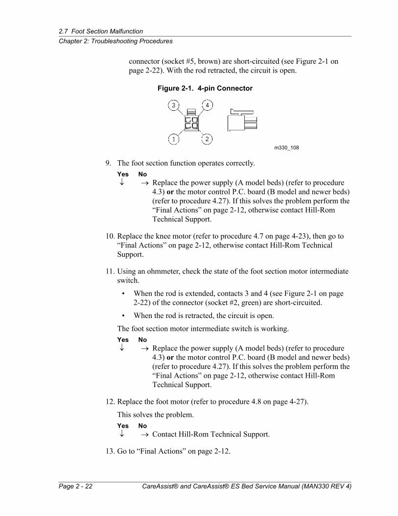
connector (socket #5, brown) are short-circuited (see Figure 2-1 on page 2-22). With the rod retracted, the circuit is open.
Figure 2-1. 4-pin Connector
m330_108
9. The foot section function operates correctly. Yes No ↓ → Replace the power supply (A model beds) (refer to procedure
4.3) or the motor control P.C. board (B model and newer beds) (refer to procedure 4.27). If this solves the problem perform the “Final Actions” on page 2-12, otherwise contact Hill-Rom Technical Support.
10. Replace the knee motor (refer to procedure 4.7 on page 4-23), then go to “Final Actions” on page 2-12, otherwise contact Hill-Rom Technical Support.
11. Using an ohmmeter, check the state of the foot section motor intermediate switch.
• When the rod is extended, contacts 3 and 4 (see Figure 2-1 on page 2-22) of the connector (socket #2, green) are short-circuited.
• When the rod is retracted, the circuit is open.
The foot section motor intermediate switch is working. Yes No ↓ → Replace the power supply (A model beds) (refer to procedure
4.3) or the motor control P.C. board (B model and newer beds) (refer to procedure 4.27). If this solves the problem perform the “Final Actions” on page 2-12, otherwise contact Hill-Rom Technical Support.
12. Replace the foot motor (refer to procedure 4.8 on page 4-27).
This solves the problem. Yes No ↓ → Contact Hill-Rom Technical Support.
13. Go to “Final Actions” on page 2-12.
Page 2 - 22 CareAssist® and CareAssist® ES Bed Service Manual (MAN330 REV 4)
2.8 Trendelenburg/Reverse Trendelenburg Malfunction Chapter 2: Troubleshooting Procedures
2.8 Trendelenburg/Reverse Trendelenburg Malfunction
Initial conditions: the hilow function works (see “Function Checks” on page 2-5).
1. At least one of the other functions is working. Yes No ↓ → Go to RAP 2.1.
2. Do the following to make sure the caregiver controls operate correctly.
a. Disconnect the control unit.
b. Connect a known good control unit.
The trendelenburg/reverse trendelenburg function works. Yes No ↓ → Replace the power supply (A model beds) (refer to procedure
4.3) or the motor control P.C. board (B model and newer beds) (refer to procedure 4.27). If this solves the problem perform the “Final Actions” on page 2-12, otherwise contact Hill-Rom Technical Support.
3. Replace the affected control unit.
This solves the problem. Yes No ↓ → Contact Hill-Rom Technical Support.
4. Go to “Final Actions” on page 2-12.
2
CareAssist® and CareAssist® ES Bed Service Manual (MAN330 REV 4) Page 2 - 23
2.9 Bed Connected to AC Power, Brakes Not Applied Detection Malfunction Chapter 2: Troubleshooting Procedures
2.9 Bed Connected to AC Power, Brakes Not Applied Detection Malfunction
Initial conditions: the hilow function works (see “Function Checks” on page 2-5).
1. At least one of the other functions is working. Yes No ↓ → Go to RAP 2.1.
2. Do the following to make sure the brake detection switch is connected correctly.
a. Remove the foot end frame cover.
b. Make sure the brake detection switch connector is correctly connected to the foot column connector under the cable cover.
The Bed Connected to AC Power But Brake Not Applied Detector operates correctly. Yes No ↓ → Go to step 4.
3. Do the “Function Checks” on page 2-5.
4. Do the following to make sure the brake detection switch operates correctly.
a. Disconnect the 2-pin connector at the bottom of the foot column.
b. Using a digital multimeter, set to ohms, at the terminals of the brake detection switch, check that the brake detection switch operates correctly.
• Idle (not braked), circuit closed
• Active (braked), circuit open
The switch operates correctly. Yes No ↓ → Replace the brake detection switch and brake detection cabling
subassembly (refer to procedure 4.11 on page 4-38), then go to to “Final Actions” on page 2-12).
5. Do the following to make sure the foot column cables are connected correctly.
a. Reconnect the 2-pin connector to the bottom of the foot column.
Page 2 - 24 CareAssist® and CareAssist® ES Bed Service Manual (MAN330 REV 4)
2.9 Bed Connected to AC Power, Brakes Not Applied Detection Malfunction Chapter 2: Troubleshooting Procedures
b. Disconnect the foot column extension cable in the central rail of the bed frame.
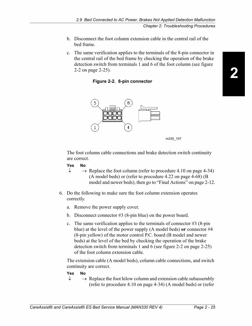
c. The same verification applies to the terminals of the 8-pin connector in the central rail of the bed frame by checking the operation of the brake detection switch from terminals 1 and 6 of the foot column (see figure 2-2 on page 2-25).
Figure 2-2. 8-pin connector 2
m330_107
The foot column cable connections and brake detection switch continuity are correct. Yes No ↓ → Replace the foot column (refer to procedure 4.10 on page 4-34)
(A model beds) or (refer to procedure 4.22 on page 4-68) (B model and newer beds), then go to “Final Actions” on page 2-12.
6. Do the following to make sure the foot column extension operates correctly.
a. Remove the power supply cover.
b. Disconnect connector #3 (8-pin blue) on the power board.
c. The same verification applies to the terminals of connector #3 (8-pin blue) at the level of the power supply (A model beds) or connector #4 (8-pin yellow) of the motor control P.C. board (B model and newer beds) at the level of the bed by checking the operation of the brake detection switch from terminals 1 and 6 (see figure 2-2 on page 2-25) of the foot column extension cable.
The extension cable (A model beds), column cable connections, and switch continuity are correct. Yes No ↓ → Replace the foot hilow column and extension cable subassembly
(refer to procedure 4.10 on page 4-34) (A model beds) or (refer
CareAssist® and CareAssist® ES Bed Service Manual (MAN330 REV 4) Page 2 - 25
2.9 Bed Connected to AC Power, Brakes Not Applied Detection Malfunction Chapter 2: Troubleshooting Procedures
to procedure 4.22 on page 4-68) (B model and newer beds). If this solves the problem perform the “Final Actions” on page 2-12, otherwise contact Hill-Rom technical support.
7. Replace the power supply (A model beds) (refer to procedure 4.3) or the motor control P.C. board (B model and newer beds) (refer to procedure 4.27).
This solves the problem. Yes No ↓ → Contact Hill-Rom technical support.
8. Go to “Final Actions” on page 2-12.
Page 2 - 26 CareAssist® and CareAssist® ES Bed Service Manual (MAN330 REV 4)
2.10 CPR Malfunction Chapter 2: Troubleshooting Procedures
2.10 CPR Malfunction
Initial conditions: the hilow function works (see “Function Checks” on page 2-5).
1. Check the mechanics of the CPR system:
Remove the seat, knee and foot sleep deck sections. Make sure the mounting hardware is not damaged or missing from the release mechanism of the head section motor.
All hardware is secure and not damaged. Yes No ↓ → Replace the missing or damaged parts, and then go to “Function
Checks” on page 2-5.
2. Check that the release cable is not broken or damaged.
The cable is intact. Yes No ↓ → Go to step 4.
3. Check that the adjustment of the release cable is correct (refer to procedure 4.6 on page 4-20).
The adjustment is correct. Yes No ↓ → Adjust the release cable (refer to procedure 4.6 on page 4-20).
4. Replace the head section motor (refer to procedure 4.5 on page 4-15) and release cable subassembly (refer to procedure 4.6 on page 4-20).
This solves the problem. Yes No ↓ → Contact Hill-Rom technical support.
5. Go to “Final Actions” on page 2-12.
2
CareAssist® and CareAssist® ES Bed Service Manual (MAN330 REV 4) Page 2 - 27
2.11 Braking Malfunction Chapter 2: Troubleshooting Procedures
2.11 Braking Malfunction
1. Check that the screws or supports are not damaged, loose, or missing from the caster attachments.
All the supports and screws are secure and not damaged. Yes No ↓ → Replace the missing parts, and then go to “Function Checks” on
page 2-5.
2. Check the brake/steer bar. Set it to the brake position, and then check that the four casters are locked by trying to move the bed.
The braking is correct. Yes No ↓ → Replace the caster(s) (refer to procedure 4.13 on page 4-44), then
go to “Final Actions” on page 2-12.
3. This solves the problem. Yes No ↓ → Contact Hill-Rom technical support.
4. Go to “Final Actions” on page 2-12.
Page 2 - 28 CareAssist® and CareAssist® ES Bed Service Manual (MAN330 REV 4)
2.12 Steering Malfunction Chapter 2: Troubleshooting Procedures
2.12 Steering Malfunction
1. Set the brake/steer bar to the brake position. Check that the screws or supports are not damaged, loose or missing from the caster attachments.
All the supports and screws are secure and not damaged. Yes No ↓ → Replace the missing parts, and then go to “Function Checks” on
page 2-5.
2. Check the steering function. Set the brake/steer bar to the steer position, push the bed lengthways, and check that the foot left caster locks in the lengthways direction of the bed.
The caster locks in the lengthways direction. Yes No ↓ → Replace the caster (refer to procedure 4.13 on page 4-44). If this
solves the problem perform the “Final Actions” on page 2-12, otherwise contact Hill-Rom technical support.
3. This solves the problem. Yes No ↓ → Contact Hill-Rom technical support.
4. Go to “Final Actions” on page 2-12.
2
CareAssist® and CareAssist® ES Bed Service Manual (MAN330 REV 4) Page 2 - 29
2.13 Scale Error 0 Chapter 2: Troubleshooting Procedures
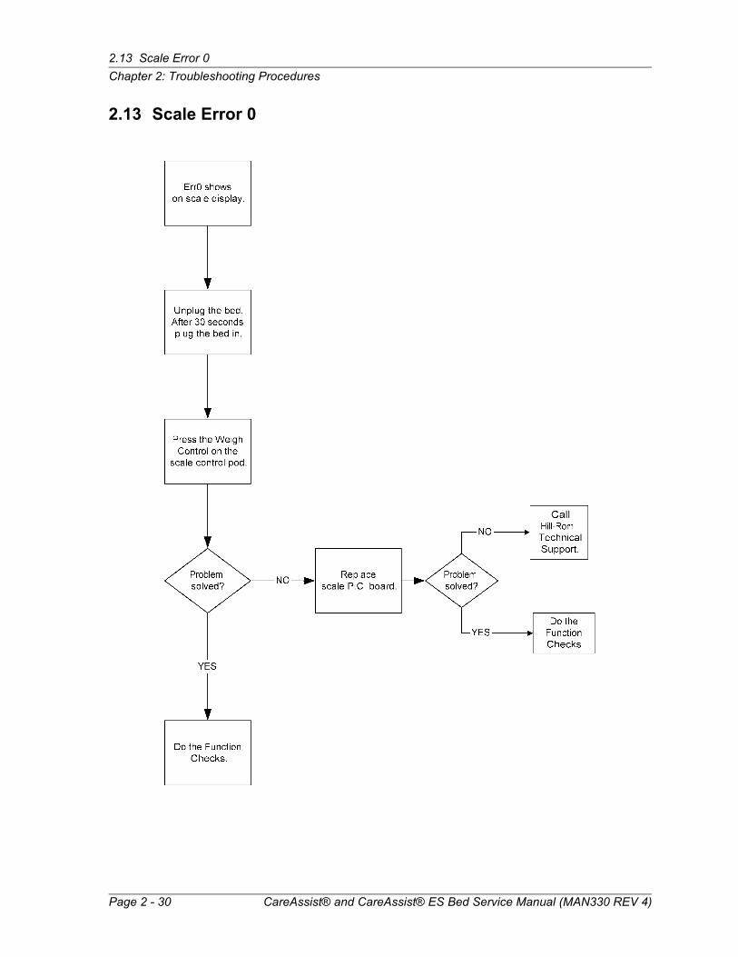
2.13 Scale Error 0
Page 2 - 30 CareAssist® and CareAssist® ES Bed Service Manual (MAN330 REV 4)
2.14 Scale Error 1 Chapter 2: Troubleshooting Procedures
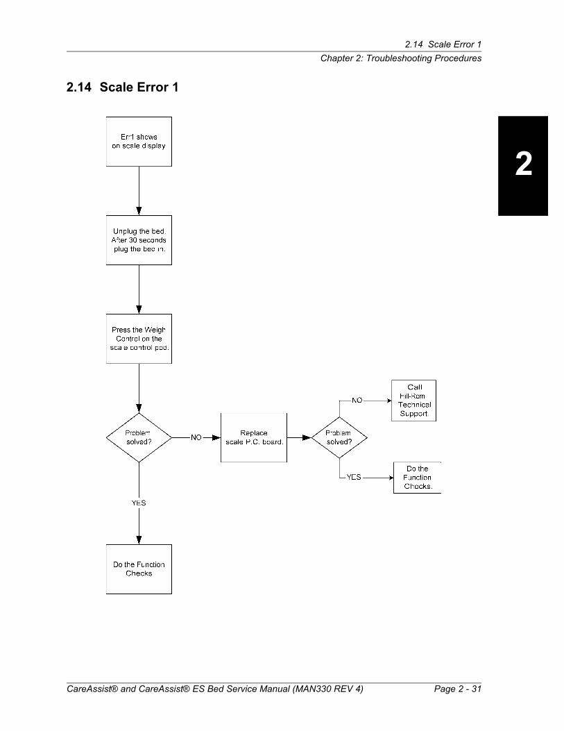
2.14 Scale Error 1
2
CareAssist® and CareAssist® ES Bed Service Manual (MAN330 REV 4) Page 2 - 31
2.15 Scale Error 2 Chapter 2: Troubleshooting Procedures
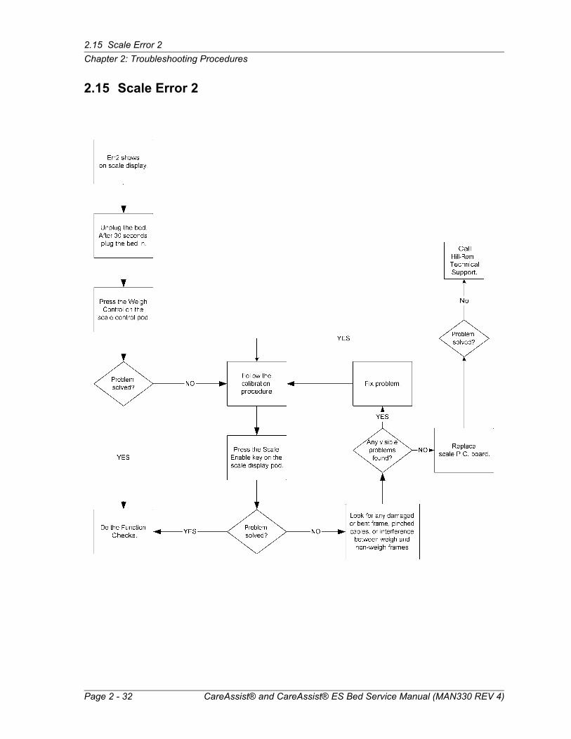
2.15 Scale Error 2
Page 2 - 32 CareAssist® and CareAssist® ES Bed Service Manual (MAN330 REV 4)
2.16 Scale Error 3 Chapter 2: Troubleshooting Procedures
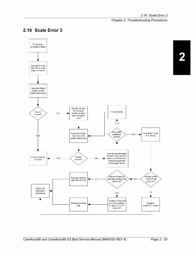
2.16 Scale Error 3
2
CareAssist® and CareAssist® ES Bed Service Manual (MAN330 REV 4) Page 2 - 33
2.17 Scale Error 5 Chapter 2: Troubleshooting Procedures
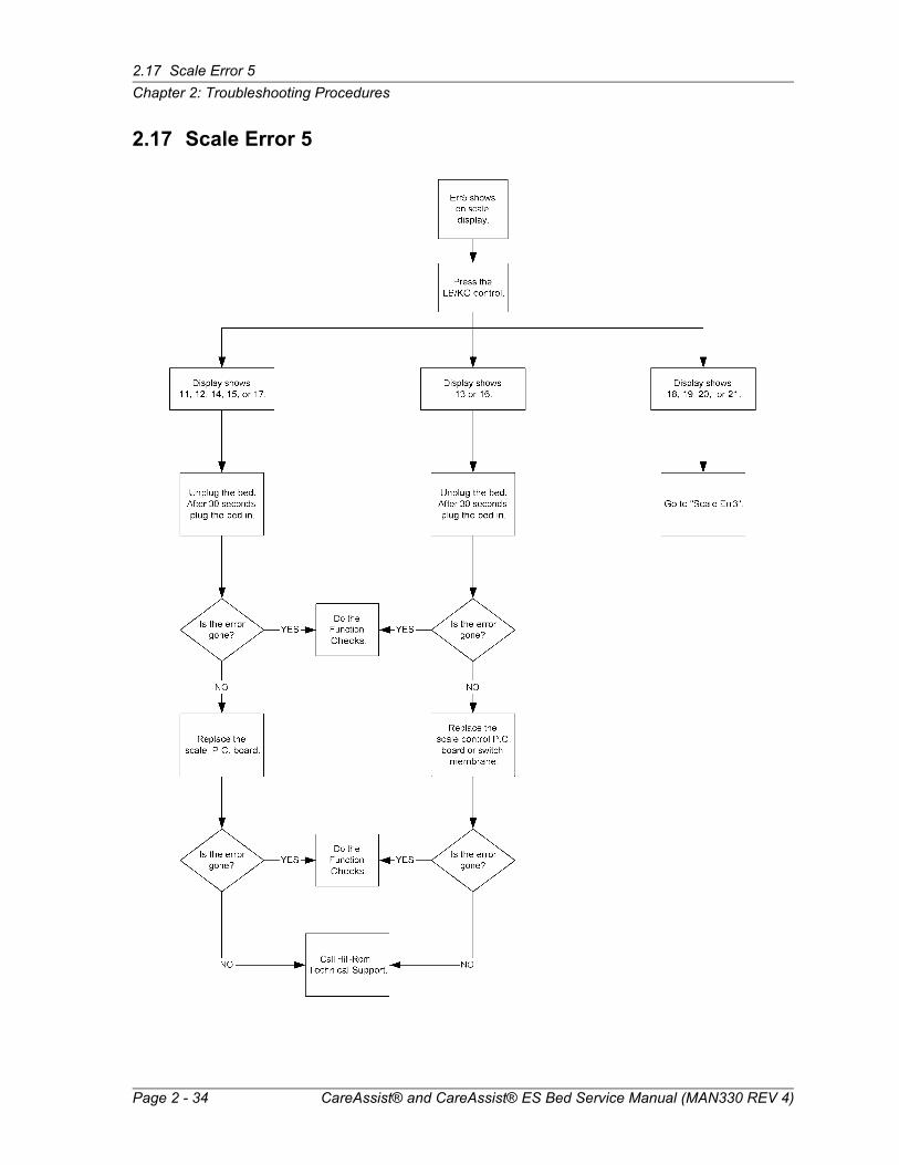
2.17 Scale Error 5
Page 2 - 34 CareAssist® and CareAssist® ES Bed Service Manual (MAN330 REV 4)
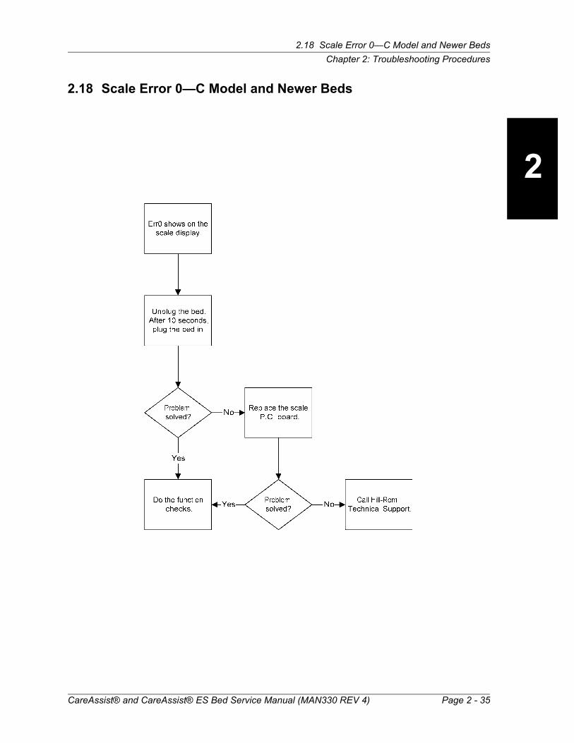
2.18 Scale Error 0—C Model and Newer Beds Chapter 2: Troubleshooting Procedures
2.18 Scale Error 0—C Model and Newer Beds
2
CareAssist® and CareAssist® ES Bed Service Manual (MAN330 REV 4) Page 2 - 35
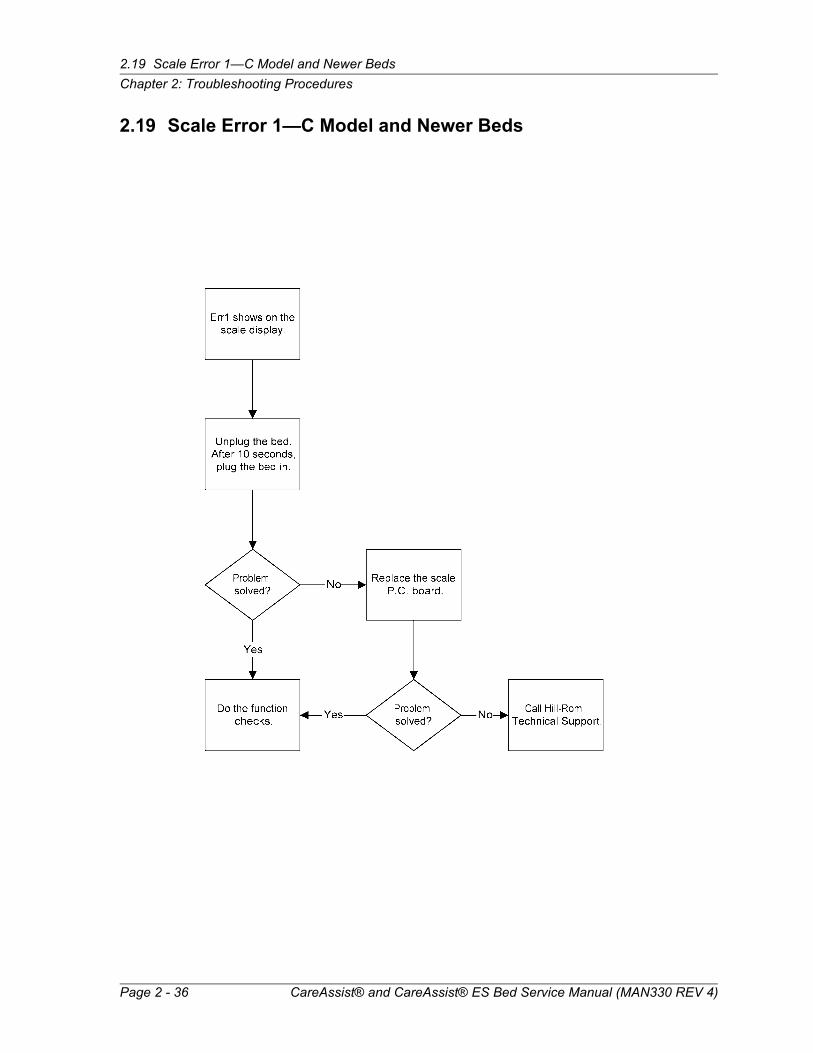
2.19 Scale Error 1—C Model and Newer Beds Chapter 2: Troubleshooting Procedures
2.19 Scale Error 1—C Model and Newer Beds
Page 2 - 36 CareAssist® and CareAssist® ES Bed Service Manual (MAN330 REV 4)
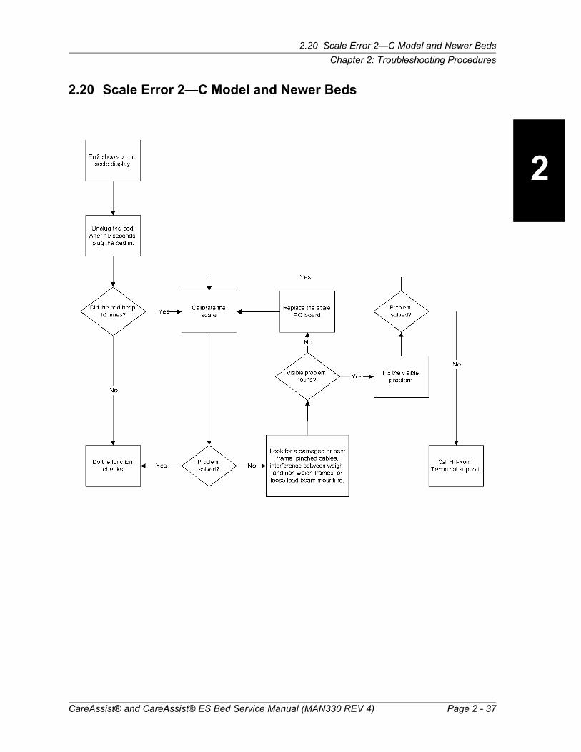
2.20 Scale Error 2—C Model and Newer Beds Chapter 2: Troubleshooting Procedures
2.20 Scale Error 2—C Model and Newer Beds
2
CareAssist® and CareAssist® ES Bed Service Manual (MAN330 REV 4) Page 2 - 37
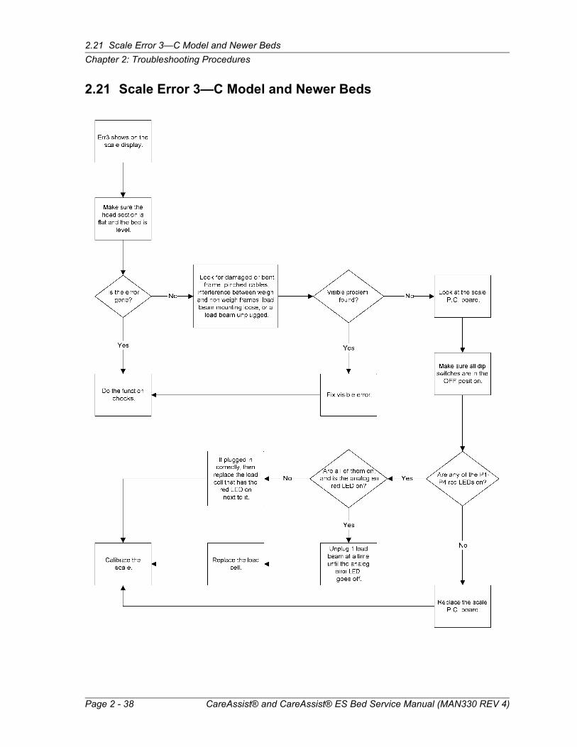
2.21 Scale Error 3—C Model and Newer Beds Chapter 2: Troubleshooting Procedures
2.21 Scale Error 3—C Model and Newer Beds
Page 2 - 38 CareAssist® and CareAssist® ES Bed Service Manual (MAN330 REV 4)
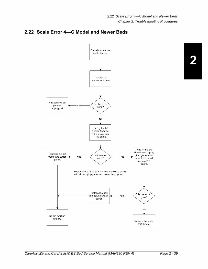
2.22 Scale Error 4—C Model and Newer Beds Chapter 2: Troubleshooting Procedures
2.22 Scale Error 4—C Model and Newer Beds
2
CareAssist® and CareAssist® ES Bed Service Manual (MAN330 REV 4) Page 2 - 39
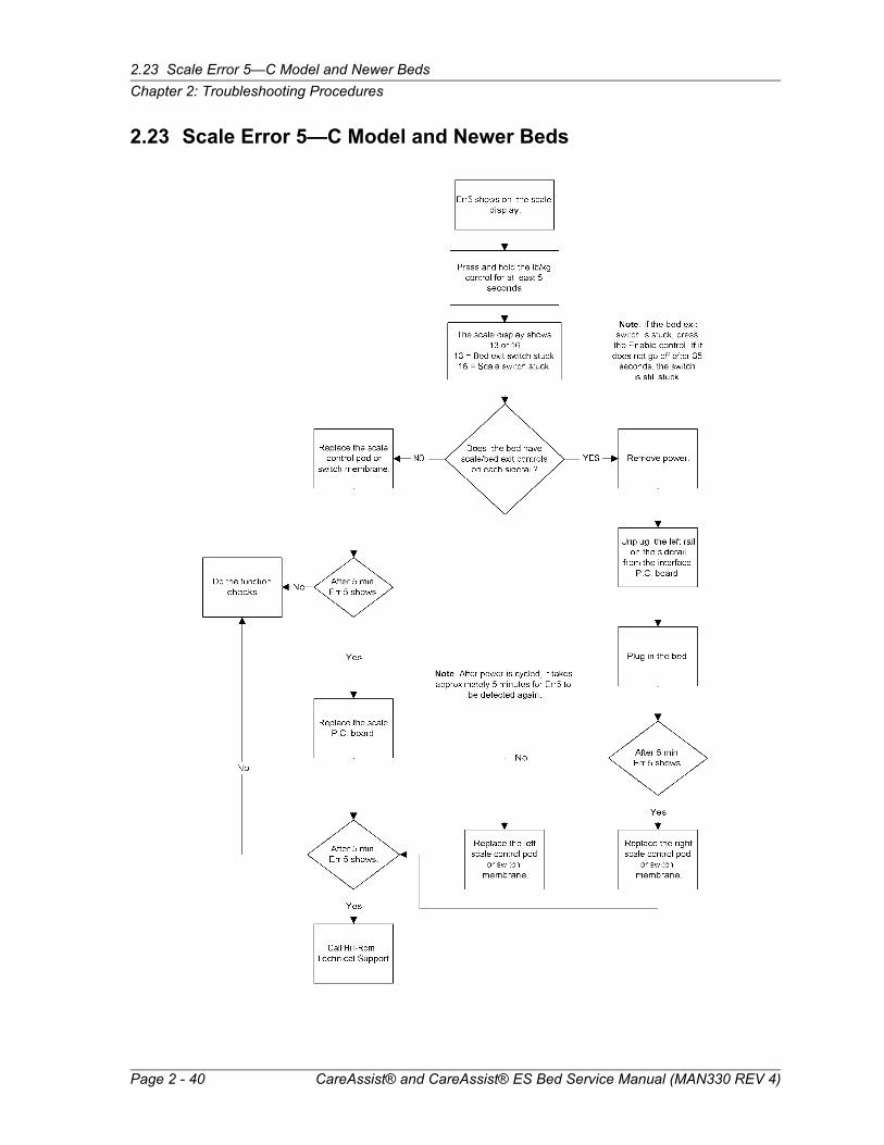
2.23 Scale Error 5—C Model and Newer Beds Chapter 2: Troubleshooting Procedures
2.23 Scale Error 5—C Model and Newer Beds
Page 2 - 40 CareAssist® and CareAssist® ES Bed Service Manual (MAN330 REV 4)
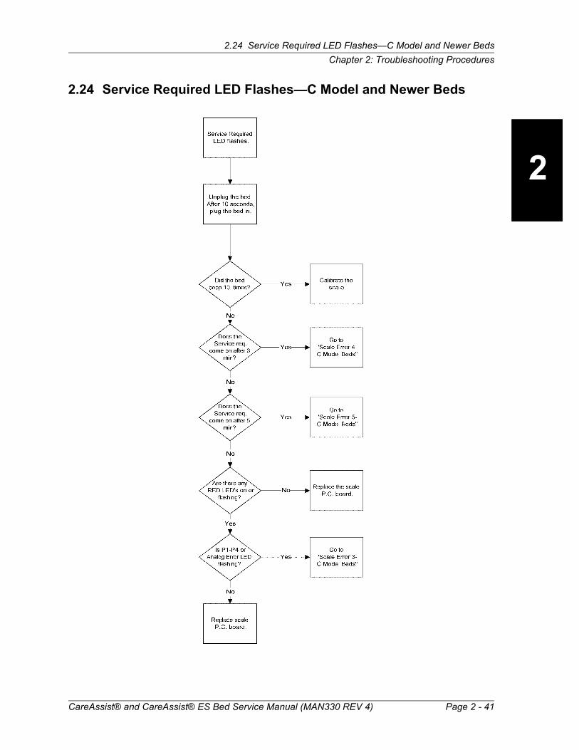
2.24 Service Required LED Flashes—C Model and Newer Beds Chapter 2: Troubleshooting Procedures
2.24 Service Required LED Flashes—C Model and Newer Beds
2
CareAssist® and CareAssist® ES Bed Service Manual (MAN330 REV 4) Page 2 - 41
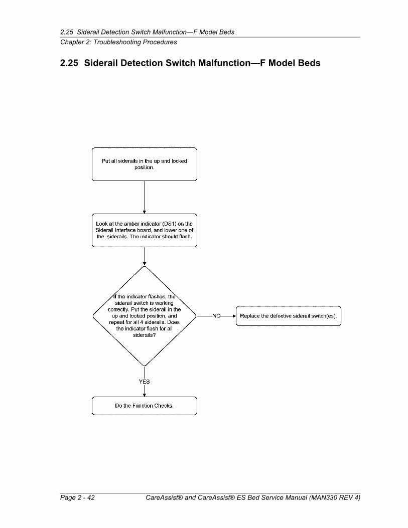
2.25 Siderail Detection Switch Malfunction—F Model Beds Chapter 2: Troubleshooting Procedures
2.25 Siderail Detection Switch Malfunction—F Model Beds
Page 2 - 42 CareAssist® and CareAssist® ES Bed Service Manual (MAN330 REV 4)
Chapter 3 Theory of Operation
Introduction
The Theories of Operation for the CareAssist® and CareAssist® ES Bed are as follows:
• Mechanical System
• Electrical System (A model beds)
• Electrical System (B model beds)
The interaction between these subsystems lets all the operational functions be used.
The electrical functions are driven by low voltage actuators.
Each of the subsystems is described separately in the following sections. The schematic diagrams are located at the end of this chapter.
3
CareAssist® and CareAssist® ES Bed Service Manual (MAN330 REV 4) Page 3 - 1
Mechanical System Chapter 3: Theory of Operation
Mechanical System
The mechanical subsystem consists of two connected systems:
• Bed frame
• Sleep surface
Retractable Head Section
The retractable head section feature is achieved by controlling a sliding movement of the head section frame with two sliding blocks in channels at each side of the intermediate frame. This lets the head section frame extend (with respect to the seat section). The hard surface also extends (with respect to the head section frame) towards the head end. This is achieved by the two elevation arms of the head section frame that terminate in gear teeth interfaced with the notches in the rear of the head section hard surface and move the hard surface towards the head end as the head section is raised.
Emergency CPR Release
The CPR control handles are located at the head end of the bed, under each corner of the sleep deck. Pulling one of the handles disengages the driving gear of the head section motor inside the actuator. This lets the head section drop under the pull of gravity, assisted by 1 spring, cushioned by one damper.
Extendable Foot Section
The extendable foot section lets the caregiver add an additional 4" (102 mm) to the length of the bed. The movement is controlled by a lever under the foot end of the bed. Pulling up on the lever and pulling the foot section out, extends the section. The foot section locks into place when extended or retracted.
Hilow System
WARNING: The column must be replaced if it becomes defective. The column must never be dismantled. Failure to observe this warning could cause personal injury.
The hilow system features two columns each composed of three sections that slide in relation with each other by a pantograph system. This system is driven by a fixed motor installed at the base of the mechanism. This system lets the
Page 3 - 2 CareAssist® and CareAssist® ES Bed Service Manual (MAN330 REV 4)
Mechanical System Chapter 3: Theory of Operation
unit travel up or down 15.7" (400 mm). Upper and lower end of travel (EOT) switches that are backed up to make sure of electrical security. The system does not require any special maintenance during its designed period of use. However, the columns can be replaced in the event of a failure, but should never be dismantled or repaired except by Hill-Rom personnel.
Casters
The bed has four casters: three brake and one brake/steer. Each caster has a 30° inclination activation mechanism and three positions:
• Brake caster—Brake/Neutral/Neutral
• Steer caster—Brake/Neutral/Steer
The brake/steer caster is located on the left side, foot end. Antistatic brake casters are standard for the remaining caster positions. They are identified by a yellow dot on the tire.
Braking
The braking system comprises four brake casters that are controlled by the brake/steer bar. The bar consists of two hexagonal bars with a connecting bar situated in the right-hand box-section of the lower frame. The brake/steer bar is directly mounted on the foot end hexagonal bar of the bed.
Steering
The left foot end caster is the steering caster. It is controlled by the brake/steer bar.
Head and Footboards
The headboard and footboard feature an extruded/blow-moulded plastic structure with chrome-plated steel clasps for assembly and decorative laminated panels. The headboard and footboard are interchangeable and can be used as a CPR backboard.
3
CareAssist® and CareAssist® ES Bed Service Manual (MAN330 REV 4) Page 3 - 3
Electrical System (A Model Beds) Chapter 3: Theory of Operation
Electrical System (A Model Beds)
The specifications of the bed are as follows:
Table 3-1. Specifications
Description Specification
Type CareAssist® Bed Type of protection against electric shock (according to IEC 60601-1)
Class I
Degree of protection against electric shock (according to IEC 60601-1)
Type B
Protection against harmful ingress of water (according to IEC 60529)
IPX4
Intermittent operation 10% 3 min/30 min Voltage 120 V (+10%, -15%) AC
voltage and earth Frequency 60 Hz Maximum power load 4.2 A
Refer to the schematic diagram at the end of this section to obtain specific information for the cabling.
The bed is operated by a power supply unit. This unit controls the electrical functions of the bed: hilow, head section and knee section with automatic contour, and foot section.
These functions are performed by motors using very low voltages.
Page 3 - 4 CareAssist® and CareAssist® ES Bed Service Manual (MAN330 REV 4)
Electrical System (A Model Beds) Chapter 3: Theory of Operation
Power Supply Unit Characteristics
Table 3-2. Power Supply Unit Characteristics
Description Specification
Input characteristics (see table 3-1 on page 3-4) Fuse rating on primary 2.2 Slo-Blo®a
Maximum power load 360 VA Output voltage 18 to 40 V AC rectified,
filtered Output power 360 VA Continuos operation at 10 VA
a. Slo-Blo® is a registered trademark of LittleFuse, Inc.
The power supply unit is composed of the following components:
• Power stage
• Functions controlled by relays and transistors
• Battery charging circuit
• Control logic and specific functions
The functions are activated after electronically unlocking each of them by using one of the following:
• Patient pendant
• Caregiver controls
Power Stage The power stage is composed of a 120 V AC input transformer, protected at the input by 2 antisurge fuses of 2.2 A and an internal thermal cutout that cannot be reset. There is one non-fused secondary for the main control board and 1 fused secondary for the rest of the circuitry both followed at the outputs by bridge rectifiers and filter capacitors. The value of this antisurge fuse is 1 A.
The non-fused secondary, through the bridge rectifier and filter capacitor, produces an output voltage VDC1 which is approximately 24 V DC and unregulated. The fused secondary produces a soft regulated 12 V DC for use in the SideCom® Communication System P.C. board and Bed Exit System. The available power enables several functions to be controlled simultaneously.
3
CareAssist® and CareAssist® ES Bed Service Manual (MAN330 REV 4) Page 3 - 5

Electrical System (A Model Beds) Chapter 3: Theory of Operation
Function Control
The motors are controlled by relays. In order to protect these relays from electrical sparks during switching, the second FET transistor checks the delay power when a function is activated, thus allowing the switches to close with no voltage. In the same way, when a function control is released, the FET transistor cuts the power before the contact opens.
Overload limiting is provided by permanently controlling the current at the output of each motor. In the event of overload or mechanical blockage, the supply of the relevant motor is cut off by a control transistor without affecting the operation of the other motors, except for specific situations. In this case, the overload is indicated by an audible alarm. This overload indication also enables failure of a motor end of travel to be detected, except for the hilow columns, which have a backup end of travel.
Battery Circuit
The bed is equipped with battery backup. This battery backup is internal to the power supply unit. The charging circuit, situated in the power supply unit, has current limiting according to the level of the battery charge. Charging begins as soon as the unit is switched on. At the end of charging, the load current is very low.
When the power supply is disconnected from the AC power, the battery backup is activated by pressing the Battery control on the caregiver controls.
The battery charge level is controlled. In this way, a flashing indicator and an audible low battery alarm by buzzer are activated during movement if the battery voltage drops (this is a continuous beep of several seconds that is heard each time a control is pressed).
After connecting to the power outlet, the indicator continues to flash until the battery has charged.
Battery operation is automatically stopped 30 seconds after the end of the last movement.
Page 3 - 6 CareAssist® and CareAssist® ES Bed Service Manual (MAN330 REV 4)
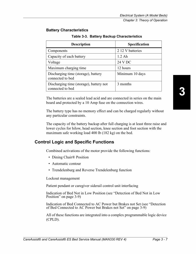
Electrical System (A Model Beds) Chapter 3: Theory of Operation
Battery Characteristics Table 3-3. Battery Backup Characteristics
Description Specification
Components 2 12 V batteries Capacity of each battery 1.2 Ah Voltage 24 V DC Maximum charging time 12 hours Discharging time (storage), battery connected to bed
Minimum 10 days
Discharging time (storage), battery not connected to bed
3 months
The batteries are a sealed lead acid and are connected in series on the main board and protected by a 10 Amp fuse on the connection wires.
The battery type has no memory effect and can be charged regularly without any particular constraints.
The capacity of the battery backup after full charging is at least three raise and lower cycles for hilow, head section, knee section and foot section with the maximum safe working load 400 lb (182 kg) on the bed.
Control Logic and Specific Functions
Combined activations of the motor provide the following functions:
• Dining Chair® Position
• Automatic contour
• Trendelenburg and Reverse Trendelenburg function
Lockout management
Patient pendant or caregiver siderail control unit interfacing
Indication of Bed Not in Low Position (see “Detection of Bed Not in Low Position” on page 3-9)
Indication of Bed Connected to AC Power but Brakes not Set (see “Detection of Bed Connected to AC Power but Brakes not Set” on page 3-9)
All of these functions are integrated into a complex programmable logic device (CPLD).
3
CareAssist® and CareAssist® ES Bed Service Manual (MAN330 REV 4) Page 3 - 7
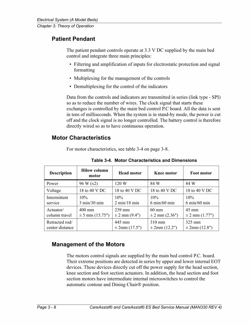
Electrical System (A Model Beds) Chapter 3: Theory of Operation
Patient Pendant
The patient pendant controls operate at 3.3 V DC supplied by the main bed control and integrate three main principles:
• Filtering and amplification of inputs for electrostatic protection and signal formatting
• Multiplexing for the management of the controls
• Demultiplexing for the control of the indicators
Data from the controls and indicators are transmitted in series (link type - SPI) so as to reduce the number of wires. The clock signal that starts these exchanges is controlled by the main bed control P.C board. All the data is sent in tens of milliseconds. When the system is in stand-by mode, the power is cut off and the clock signal is no longer controlled. The battery control is therefore directly wired so as to have continuous operation.
Motor Characteristics
For motor characteristics, see table 3-4 on page 3-8.
Table 3-4. Motor Characteristics and Dimensions
Description Hilow column motor Head motor Knee motor Foot motor
Power 96 W (x2) 120 W 84 W 84 W Voltage 18 to 40 V DC 18 to 40 V DC 18 to 40 V DC 18 to 40 V DC Intermittent 10% 10% 10% 10% service 3 min/30 min 2 min/18 min 6 min/60 min 6 min/60 min Actuator/ 400 mm 239 mm 60 mm 45 mm column travel ± 5 mm (15.75") ± 2 mm (9.4") ± 2 mm (2.36") ± 2 mm (1.77") Retracted rod/ 445 mm 310 mm 325 mm center distance ± 2mm (17.5") ± 2mm (12.2") ± 2mm (12.8")
Management of the Motors
The motors control signals are supplied by the main bed control P.C. board. Their extreme positions are detected in series by upper and lower internal EOT devices. These devices directly cut off the power supply for the head section, knee section and foot section actuators. In addition, the head section and foot section motors have intermediate internal microswitches to control the automatic contour and Dining Chair® position.
Page 3 - 8 CareAssist® and CareAssist® ES Bed Service Manual (MAN330 REV 4)
Electrical System (A Model Beds) Chapter 3: Theory of Operation
The two hilow columns also have upper and lower internal EOT devices. For safety reasons, they are both backed up at each end. If one of these safety devices is activated, the column cannot be used; however the other functions remain operational.
Complementing these EOT devices, the overload limiting function of the power supply unit provides protection in the event of mechanical failures, obstacles, or overload.
Detection of Bed Not in Low Position
This type of detection is obtained by taking into account the state of the low EOT of the hilow columns. The power supply unit controls the corresponding indicator of the control unit as soon as one of the two EOTs is released.
Automatic Contour
The power supply, when it received a command from the control unit, controls the automatic contour (head section and thigh section) operation of the bed. This function is carried out through an intermediate switch of the thigh section actuator. When the Head Up function is activated from the horizontal position, the head section and knee section rise until the intermediate internal microswitch of the knee section actuator cuts its power at approximately 20°. The head section actuator continues to operate until its upper EOT is reached or the control is released. When the Head Down function is activated and the head section reaches the low position, the knee section actuator continues operating until its lower EOT is reached or the control is released.
Dining Chair® Position The Dining Chair® Position function combines the movements of the bed frame sections and uses the intermediate internal microswitches of the knee section and foot section motors to control the interaction between these two sections.
Detection of Bed Connected to AC Power but Brakes Not Set The detection system operates by a normal on switch, mounted on the foot end crossbar and is activated by the brake/steer bar. The power supply unit controls an audible alarm if the following two elements occur together: AC power is present and the switch not activated. The audible alarm stops when the brake is applied or when the bed is unplugged from the power source.
3
CareAssist® and CareAssist® ES Bed Service Manual (MAN330 REV 4) Page 3 - 9
Electrical System (A Model Beds) Chapter 3: Theory of Operation
Trendelenburg/Reverse Trendelenburg The Trendelenburg/Reverse Trendelenburg is a fully electric function accessed by the caregiver. The function is enabled by the Enable control on the caregiver siderail controls. The principle involves controlling the two hilow columns in opposing directions according to the position required, regardless of the initial height and position of the sleep surface. As long as one of the two controls remains pressed, the two columns continue to move until their internal EOT (end of travel) is reached. The maximum inclination can be reached as long as AC power or battery backup is available.
Page 3 - 10 CareAssist® and CareAssist® ES Bed Service Manual (MAN330 REV 4)
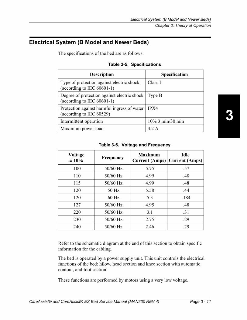
Electrical System (B Model and Newer Beds) Chapter 3: Theory of Operation
Electrical System (B Model and Newer Beds)
The specifications of the bed are as follows:
Table 3-5. Specifications
Description Specification
Type of protection against electric shock (according to IEC 60601-1)
Class I
Degree of protection against electric shock (according to IEC 60601-1)
Type B
Protection against harmful ingress of water (according to IEC 60529)
IPX4
Intermittent operation 10% 3 min/30 min Maximum power load 4.2 A
3
Table 3-6. Voltage and Frequency
Voltage ± 10% Frequency Maximum
Current (Amps) Idle
Current (Amps)
100 50/60 Hz 5.75 .57 110 50/60 Hz 4.99 .48 115 50/60 Hz 4.99 .48 120 50 Hz 5.58 .44 120 60 Hz 5.3 .184 127 50/60 Hz 4.95 .48 220 50/60 Hz 3.1 .31 230 50/60 Hz 2.75 .29 240 50/60 Hz 2.46 .29
Refer to the schematic diagram at the end of this section to obtain specific information for the cabling.
The bed is operated by a power supply unit. This unit controls the electrical functions of the bed: hilow, head section and knee section with automatic contour, and foot section.
These functions are performed by motors using a very low voltage.
CareAssist® and CareAssist® ES Bed Service Manual (MAN330 REV 4) Page 3 - 11
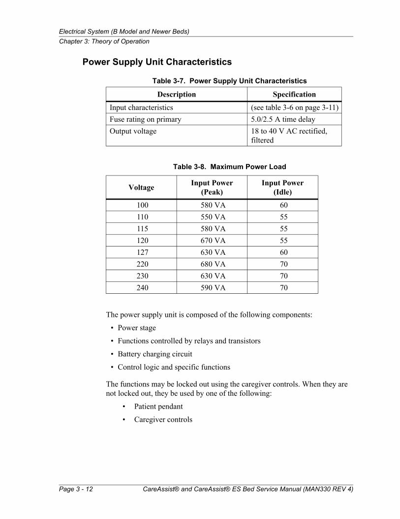
Electrical System (B Model and Newer Beds) Chapter 3: Theory of Operation
Power Supply Unit Characteristics
Table 3-7. Power Supply Unit Characteristics
Description Specification
Input characteristics (see table 3-6 on page 3-11) Fuse rating on primary 5.0/2.5 A time delay Output voltage 18 to 40 V AC rectified,
filtered
Table 3-8. Maximum Power Load
Voltage Input Power (Peak)
Input Power (Idle)
100 580 VA 60 110 550 VA 55 115 580 VA 55 120 670 VA 55 127 630 VA 60 220 680 VA 70 230 630 VA 70 240 590 VA 70
The power supply unit is composed of the following components:
• Power stage
• Functions controlled by relays and transistors
• Battery charging circuit
• Control logic and specific functions
The functions may be locked out using the caregiver controls. When they are not locked out, they be used by one of the following:
• Patient pendant
• Caregiver controls
Page 3 - 12 CareAssist® and CareAssist® ES Bed Service Manual (MAN330 REV 4)
Electrical System (B Model and Newer Beds) Chapter 3: Theory of Operation
Power Stage The power stage is composed of an AC input transformer, protected at the input by two anti-surge fuses and an internal self-resetting thermal cutout. There are two transformer options: one having a single winding primary, 120 V, 60 Hz for use in North America, and the other having two primaries, multi-tapped, for use in 100, 110, 115, 127, 220, 230, and 240 V, 50/60 Hz and 120 V, 50 Hz applications.
There are two secondaries, both of which are protected by Positive Temperature Coefficient (PTC) devices. The PTCs are located on the siderail interface P.C. board. The first secondary, nominally 24.5 V AC, supplies power to the motor control P.C. board. It is rectified and filtered by the motor control P.C. board to produce a voltage of approximately 33 V DC to supply power to the drive motors. The other secondary, nominally 14.5 V AC, is rectified, filtered, and regulated to produce a voltage of 8.5 V DC to supply power to the Scale System, Bed Exit System, and the SideCom® Communication System.
Function Control
The motors are controlled by relays and/or FET transistors. In order to protect these relays from electrical arcing during switching, the FET transistor operates such that when a function is activated, the relay closes with no current. In the same way, when a function control is released, the FET cuts the power before the relay opens.
Overload limiting is provided by controlling the current at the output of each motor. In the event of overload or mechanical blockage, the supply of the relevant motor is cut off by a control transistor without affecting the operation of the other motors, except for specific situations. In this case, the overload is indicated by an audible alarm. This overload indication also enables failure of a motor end of travel to be detected, except for the hilow columns, which have a backup end of travel.
Battery Circuit
The bed is equipped with battery backup. This battery backup is internal to the power supply unit. The charging circuit, has current limiting according to the level of the battery charge. Charging begins as soon as the unit is connected to AC power. At the end of charging, the load current is very low.
When the power supply is disconnected from the AC power, the battery backup is activated by pressing the Battery control on the caregiver controls.
3
CareAssist® and CareAssist® ES Bed Service Manual (MAN330 REV 4) Page 3 - 13
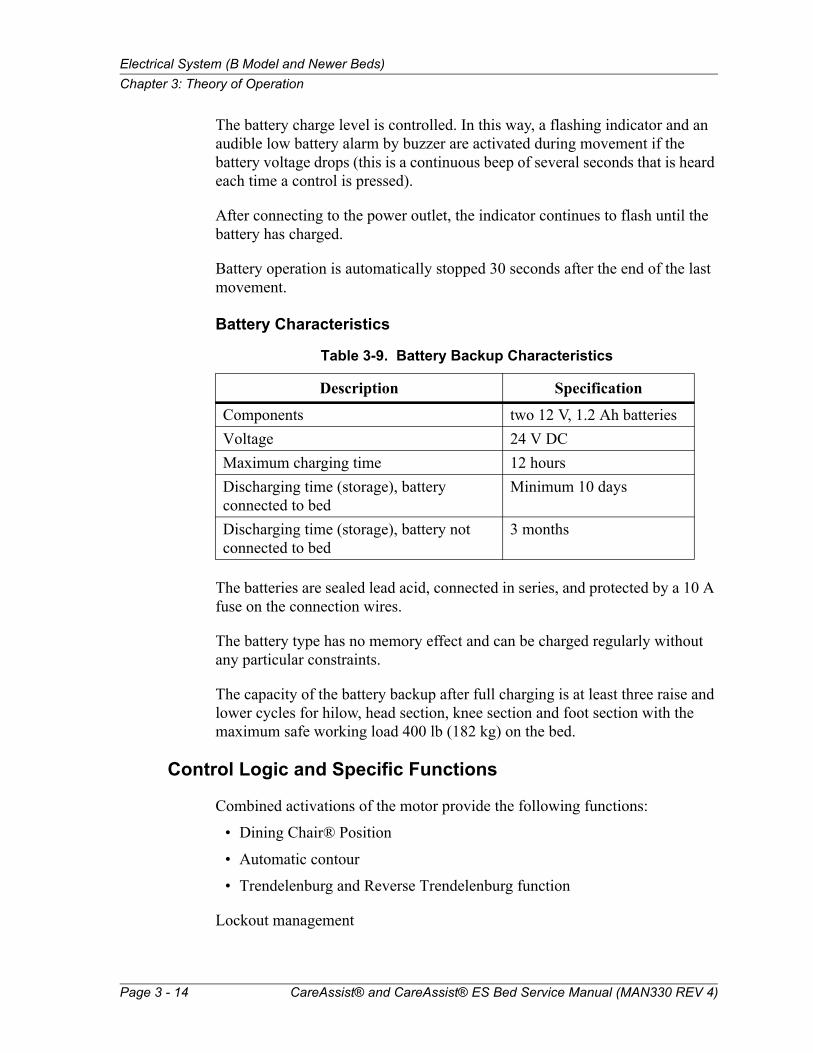
Electrical System (B Model and Newer Beds) Chapter 3: Theory of Operation
The battery charge level is controlled. In this way, a flashing indicator and an audible low battery alarm by buzzer are activated during movement if the battery voltage drops (this is a continuous beep of several seconds that is heard each time a control is pressed).
After connecting to the power outlet, the indicator continues to flash until the battery has charged.
Battery operation is automatically stopped 30 seconds after the end of the last movement.
Battery Characteristics
Table 3-9. Battery Backup Characteristics
Description Specification
Components two 12 V, 1.2 Ah batteries Voltage 24 V DC Maximum charging time 12 hours Discharging time (storage), battery connected to bed
Minimum 10 days
Discharging time (storage), battery not connected to bed
3 months
The batteries are sealed lead acid, connected in series, and protected by a 10 A fuse on the connection wires.
The battery type has no memory effect and can be charged regularly without any particular constraints.
The capacity of the battery backup after full charging is at least three raise and lower cycles for hilow, head section, knee section and foot section with the maximum safe working load 400 lb (182 kg) on the bed.
Control Logic and Specific Functions
Combined activations of the motor provide the following functions:
• Dining Chair® Position
• Automatic contour
• Trendelenburg and Reverse Trendelenburg function
Lockout management
Page 3 - 14 CareAssist® and CareAssist® ES Bed Service Manual (MAN330 REV 4)
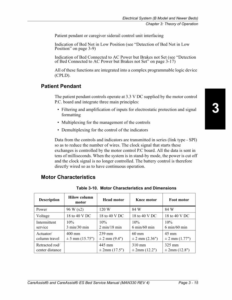
Electrical System (B Model and Newer Beds) Chapter 3: Theory of Operation
Patient pendant or caregiver siderail control unit interfacing
Indication of Bed Not in Low Position (see “Detection of Bed Not in Low Position” on page 3-9)
Indication of Bed Connected to AC Power but Brakes not Set (see “Detection of Bed Connected to AC Power but Brakes not Set” on page 3-17)
All of these functions are integrated into a complex programmable logic device (CPLD).
Patient Pendant
The patient pendant controls operate at 3.3 V DC supplied by the motor control P.C. board and integrate three main principles:
• Filtering and amplification of inputs for electrostatic protection and signal formatting
• Multiplexing for the management of the controls
• Demultiplexing for the control of the indicators
Data from the controls and indicators are transmitted in series (link type - SPI) so as to reduce the number of wires. The clock signal that starts these exchanges is controlled by the motor control P.C board. All the data is sent in tens of milliseconds. When the system is in stand-by mode, the power is cut off and the clock signal is no longer controlled. The battery control is therefore directly wired so as to have continuous operation.
Motor Characteristics
Table 3-10. Motor Characteristics and Dimensions
3
Description Hilow column motor Head motor Knee motor Foot motor
Power 96 W (x2) 120 W 84 W 84 W Voltage 18 to 40 V DC 18 to 40 V DC 18 to 40 V DC 18 to 40 V DC Intermittent 10% 10% 10% 10% service 3 min/30 min 2 min/18 min 6 min/60 min 6 min/60 min Actuator/ 400 mm 239 mm 60 mm 45 mm column travel ± 5 mm (15.75") ± 2 mm (9.4") ± 2 mm (2.36") ± 2 mm (1.77") Retracted rod/ 445 mm 310 mm 325 mm center distance ± 2mm (17.5") ± 2mm (12.2") ± 2mm (12.8")
CareAssist® and CareAssist® ES Bed Service Manual (MAN330 REV 4) Page 3 - 15
Electrical System (B Model and Newer Beds) Chapter 3: Theory of Operation
Management of the Motors
The motor control signals are supplied by the motor control P.C. board. Their extreme positions are detected in series by upper and lower internal end-oftravel (EOT) devices. These devices directly cut off the power supply for the head section, knee section, and foot section actuators. In addition, the knee section and foot section motors have intermediate internal microswitches to control the automatic contour and Dining Chair® Position.
The two hilow columns also have upper and lower internal EOT devices. For safety reasons, they are both backed up at each end. If one of these safety devices is activated, the column cannot be used; however, the other functions remain operational.
Complementing these EOT devices, the overload limiting function of the power supply unit provides protection in the event of mechanical failures, obstacles, or overload.
Detection of Bed Not in Low Position
This type of detection is obtained by taking into account the state of the low EOT of the hilow columns. The motor control P.C. board controls the corresponding indicator as soon as one of the two EOTs is released.
Automatic Contour
The motor control P.C. board, upon receiving a command from the control unit, controls the automatic contour (head section and knee section) operation of the bed. This function is carried out through an intermediate switch of the knee section actuator. When the Head Up function is activated while in the horizontal position, the head section and knee section rise until the intermediate internal microswitch of the knee section actuator cuts its power at approximately 20°. The head section actuator continues to operate until it reaches its upper EOT or its control is released. When the Head Down function is activated and the head section reaches the low position, the knee section actuator continues operating until it reaches its lower EOT or its control is released.
Dining Chair® Position The Dining Chair® Position function combines the movements of the bed frame sections and uses the intermediate internal microswitches of the knee section and foot section motors to control the interaction between these two sections.
Page 3 - 16 CareAssist® and CareAssist® ES Bed Service Manual (MAN330 REV 4)
Electrical System (B Model and Newer Beds) Chapter 3: Theory of Operation
Detection of Bed Connected to AC Power but Brakes Not Set The detection system operates by a normal on switch, mounted on the foot end crossbar and is activated by the brake/steer bar. The power supply unit controls an audible alarm if the following two elements occur together: AC power is present and the switch not activated. The audible alarm stops when the brake is applied or when the bed is unplugged from the power source.
Trendelenburg/Reverse Trendelenburg The Trendelenburg/Reverse Trendelenburg is a fully electric function accessed by the caregiver. The function is enabled by the Enable control on the caregiver siderail controls. The principle involves controlling the two hilow columns in opposing directions according to the position required, regardless of the initial height and position of the sleep surface. As long as one of the two controls remains pressed, the two columns continue to move until their internal EOT is reached. The maximum inclination can be reached as long as AC power or battery backup is available.
Scale and Bed Exit Systems—B Model Beds
Power is supplied to the Scale/Bed Exit System from the siderail interface P.C. board inside the power supply. The power supply supplies a regulated 8.6 V DC referenced to signal GND at 500mA max, 200mA typical. The GND is common among all nodes in the bed. This is important to the network transceiver explained later.
The scale P.C. board has a single chip analog solution specially designed for scale transducers. The load beams are resistive bridge sensors excited by a regulated DC voltage. This regulated voltage is supplied to the beams and to the analog to digital converter (ADC) reference input to minimize the effects of variations.
Each beam is connected to the differential input on the ADC. The multiplexer and gain (up to 128) are internally configured through software. The ADC has the ability to detect open or shorted sensors. It also has a second stage sigma-delta converter. The serial interface is SPI compatible and transfers between the micro controller on the scale P.C. board and the microcontroller on the display P.C. boards.
The Scale/Bed Exit System user interface consists of 5 seven-segment LED digits, LED indicators, and switches to start scale and bed exit functions. The scale P.C. board sends controller area network (CAN) messages to the scale display P.C. board which, illuminates the LEDs. The scale display P.C. board
3
CareAssist® and CareAssist® ES Bed Service Manual (MAN330 REV 4) Page 3 - 17
Electrical System (B Model and Newer Beds) Chapter 3: Theory of Operation
sends CAN messages to the scale P.C. board to start activation of the switches in the user interface.
All of the scale functions are done by microcontrollers on the scale P.C. board. These include:
• Weigh
• Zero scale
• Add/Delete items
• Select LB/KG display mode
The Bed Exit System functions are shared between the scale P.C. board and the scale display P.C. board. These include:
• Arm/Disarm bed exit
• Alarm tone select
• Alarm volume select
• Alarm
If the Bed Exit System is armed, AC power removed, and the bed equipped with the SideCom® Communication System, the display P.C. board will cause the SideCom® Communication System to send a nurse call. If the Bed Exit System is armed and the display P.C. board loses communication with the scale P.C. board, the display P.C. board will cause the SideCom® Communication System to send a nurse call.
When the bed is unplugged from AC power, neither scale nor the Bed Exit System will function.
Scale and Bed Exit Alarm System—C Model and Newer Beds
Power is supplied to the Scale/Bed Exit Alarm System system by the central power supply. The power supply provides a pre-regulated 8-9 V DC reference to signal GND at 400mA max, 200mA typical. The GND is common among all nodes in the bed. This is important to the network transceiver explained later.
The analog circuitry is a single chip solution specially designed for scale transducers. It is located in the frame of the bed as close to the load beams as possible. The load beams are resistive bridge sensors excited by a regulated DC voltage. This regulated voltage is supplied to the beams and to the A/D converter reference input to minimize the effects of variations.
Page 3 - 18 CareAssist® and CareAssist® ES Bed Service Manual (MAN330 REV 4)
Electrical System (B Model and Newer Beds) Chapter 3: Theory of Operation
Each beam is connected to the differential input on the A/D. The Multiplexer and Gain (up to 128) is internally configurable through software. The A/D has the ability to detect open or shorted sensors. The part has a second stage sigma-delta converter. The serial interface is SPI compatible which transfers the data to the embedded controller.
The raw digital information is translated and further filtered in software before it is put on the network. If necessary, the accelerometer or motor position can be used to detect the level of the bed with respect to the floor and then correct for the cosine error.
The display has 5 seven-segment digits. The scale node sends a network variable for the caregiver to display. Switches, located on the display board are available to the user to start functions like Zero and Display Weight. When engaged the network variable gets updated and read by the scale node.
Switches located on the outside of the head end siderail are available to the caregiver to start functions such as mode selection, off, and alarm volume level. The LEDs show the status of the Bed Exit Alarm System.
All of the Scale and Bed Exit Alarm System functions revolve around the microprocessor on the control board. This is an 8052 variant with internal 32K flash program and 256 + 1.2K EEPROM data memory. External to the microprocessor are the CAN transceiver, accelerometer, watch dog reset circuit, 2K EEPROM and audio enunciator with three volume settings.
All of the scale functions below are performed by the microcontroller on the scale P.C. board:
• Weigh
• Zero the scale
• Add/delete items
• Select the LB/KG display mode
• Manual weight adjustment
3
CareAssist® and CareAssist® ES Bed Service Manual (MAN330 REV 4) Page 3 - 19
Electrical System (B Model and Newer Beds) Chapter 3: Theory of Operation
The Bed Exit Alarm System functions below are shared between the scale P.C. board and the scale display P.C. board:
• Arm/Disarm the Bed Exit Alarm System
• Select Patient Position, Bed Exiting, and Out-of-Bed modes
• Select the alarm tone
• Select the alarm volume
• Alarm
If the Bed Exit Alarm System is armed, AC power is removed, and the bed is equipped with the SideCom®1 Communication System, the display P.C. board will cause the SideCom® Communication System to send a nurse call. If the Bed Exit System is armed and the display P.C. board loses communication with the scale P.C. board, the display P.C. board will cause the SideCom® Communication System to send a nurse call.
There is a circuit on the siderail interface P.C. board that detects when a bed articulation control (head up, head down, knee up, knee down and such) is pressed and generates a signal to the scale P.C. board. If the scale based Bed Exit Alarm System is armed, it will suspend operation in the Patient Position and Bed Exiting modes until the articulation control is released and the signal to the scale P.C. board is removed. Once the signal goes away, the Patient Position or Bed Exiting mode starts again and normal operation resumes. If any Bed Exit mode is armed, the Out-of-Bed mode is always active, even during bed articulation.
When the bed is unplugged from AC power, neither the scale nor the Bed Exit Alarm System will function.
1. SideCom® is a registered trademark of Hill-Rom Services, Inc.
Page 3 - 20 CareAssist® and CareAssist® ES Bed Service Manual (MAN330 REV 4)
Electrical System Wiring Diagram Chapter 3: Theory of Operation
Electrical System Wiring Diagram
Figure 3-1. SideCom® Communication System (A through E Model Beds)
Refer to fold-out FO 3-1 at the rear of this manual.
Figure 3-2. Siderail Interface P.C. Board—P/N 72207 and 71514 (Beds without the SafeView™ Alerts or the NaviCare® Patient Safety Module)
Refer to fold-out FO 3-2 at the rear of this manual.
Figure 3-3. Caregiver Control
Refer to fold-out FO 3-3 at the rear of this manual.
Figure 3-4. Caregiver Signal Conditioning
Refer to fold-out FO 3-4 at the rear of this manual.
Figure 3-5. Bed Control Board Power and Phase Control
Refer to fold-out FO 3-5 at the rear of this manual.
Figure 3-6. Bed Control Board Power Management
Refer to fold-out FO 3-6 at the rear of this manual.
Figure 3-7. Bed Control Board Battery Management
Refer to fold-out FO 3-7 at the rear of this manual.
Figure 3-8. Bed Control Board Clock and Divider
Refer to fold-out FO 3-8 at the rear of this manual.
Figure 3-9. Bed Control Board Relay, FET and Drivers
Refer to fold-out FO 3-9 at the rear of this manual.
3
CareAssist® and CareAssist® ES Bed Service Manual (MAN330 REV 4) Page 3 - 21
Electrical System Wiring Diagram Chapter 3: Theory of Operation
Figure 3-10. Bed Control Board PLD and Connector
Refer to fold-out FO 3-10 at the rear of this manual.
Figure 3-11. Bed Control Board Motor Current Limiter (A, B and C Model Beds)
Refer to fold-out FO 3-11 at the rear of this manual.
Figure 3-12. Bed Wiring Schematic (A Model Beds)
Refer to fold-out FO 3-12 at the rear of this manual.
Figure 3-13. Bed Wiring Schematic (B Model Beds)
Refer to fold-out FO 3-13 at the rear of this manual.
Figure 3-14. Bed Wiring Schematic (C Model and Newer Beds without the SafeView™ Alerts or the NaviCare® Patient Safety Module)
Refer to fold-out FO 3-14 at the rear of this manual.
Figure 3-15. Bed Control Board Motor Current Limiter (D Model and Newer Beds)
Refer to fold-out FO 3-15 at the rear of this manual.
Figure 3-16. SideCom® Communication System (F Model Beds)
Refer to fold-out FO 3-16 at the rear of this manual.
Figure 3-17. Siderail Interface P.C. Board (Beds with the SafeView™ Alerts or the NaviCare® Patient Safety Module)
Refer to fold-out FO 3-17 at the rear of this manual.
Figure 3-18. Bed Wiring Schematic (Beds with the SafeView™ Alerts or the NaviCare® Patient Safety Module)
Refer to fold-out FO 3-18 at the rear of this manual.
Page 3 - 22 CareAssist® and CareAssist® ES Bed Service Manual (MAN330 REV 4)
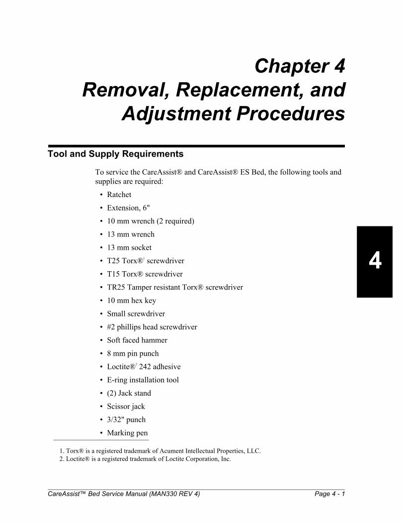
Chapter 4 Removal, Replacement, and
Adjustment Procedures
Tool and Supply Requirements
To service the CareAssist® and CareAssist® ES Bed, the following tools and supplies are required:
• Ratchet
• Extension, 6"
• 10 mm wrench (2 required)
• 13 mm wrench
• 13 mm socket
• T25 Torx®1 screwdriver
• T15 Torx® screwdriver
• TR25 Tamper resistant Torx® screwdriver
• 10 mm hex key
• Small screwdriver
• #2 phillips head screwdriver
• Soft faced hammer
• 8 mm pin punch
• Loctite®2 242 adhesive
• E-ring installation tool
• (2) Jack stand
• Scissor jack
• 3/32" punch
• Marking pen
1. Torx® is a registered trademark of Acument Intellectual Properties, LLC. 2. Loctite® is a registered trademark of Loctite Corporation, Inc.
4
CareAssist™ Bed Service Manual (MAN330 REV 4) Page 4 - 1
Tool and Supply Requirements Chapter 4: Removal, Replacement, and Adjustment Procedures
• Tape
• (2) 4" x 4" x 2' piece of wood
• Rags
• Isopropyl alcohol
• Wire cutters
• Vise-Grip®1
• Antistatic strap
• String 10' (305 cm)
• Needle nose pliers
• Small-bladed screwdriver (2)
1. Vise-Grip® is a registered trademark of American Tool Companies, Inc.
Page 4 - 2 CareAssist® and CareAssist® ES Bed Service Manual (MAN330 REV 4)
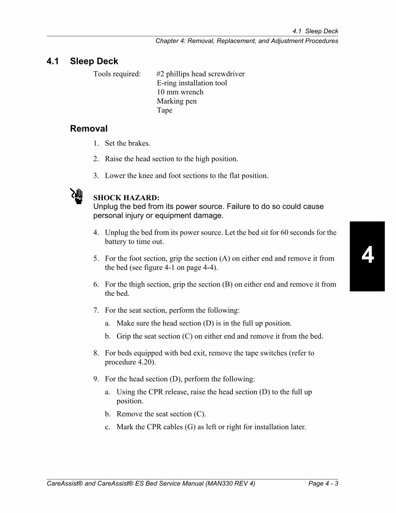
4.1 Sleep Deck Chapter 4: Removal, Replacement, and Adjustment Procedures
4.1 Sleep Deck Tools required: #2 phillips head screwdriver
E-ring installation tool 10 mm wrench Marking pen Tape
Removal 1. Set the brakes.
2. Raise the head section to the high position.
3. Lower the knee and foot sections to the flat position.
SHOCK HAZARD: Unplug the bed from its power source. Failure to do so could cause personal injury or equipment damage.
4. Unplug the bed from its power source. Let the bed sit for 60 seconds for the battery to time out.
5. For the foot section, grip the section (A) on either end and remove it from the bed (see figure 4-1 on page 4-4).
6. For the thigh section, grip the section (B) on either end and remove it from the bed.
7. For the seat section, perform the following:
a. Make sure the head section (D) is in the full up position.
b. Grip the seat section (C) on either end and remove it from the bed.
8. For beds equipped with bed exit, remove the tape switches (refer to procedure 4.20).
9. For the head section (D), perform the following:
a. Using the CPR release, raise the head section (D) to the full up position.
b. Remove the seat section (C).
c. Mark the CPR cables (G) as left or right for installation later.
4
CareAssist® and CareAssist® ES Bed Service Manual (MAN330 REV 4) Page 4 - 3
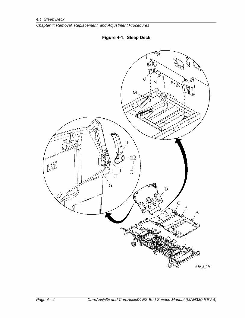
4.1 Sleep Deck Chapter 4: Removal, Replacement, and Adjustment Procedures
Figure 4-1. Sleep Deck
Page 4 - 4 CareAssist® and CareAssist® ES Bed Service Manual (MAN330 REV 4)
4.1 Sleep Deck Chapter 4: Removal, Replacement, and Adjustment Procedures
d. Remove the screw (E) securing the CPR handle (F) to the CPR mount bracket (I).
e. Remove the CPR handle (F) from the CPR cable (G).
f. Loosen, do not remove, the jam nut (H) securing the CPR cable (G) to the CPR mount bracket (I).
g. Repeat step d through step f for the other side.
h. Remove the E-ring (L) from one side of the lower hinge point (M).
i. Remove the plastic washer (N) from the lower hinge point (M).
j. Repeat step h and step i for the other side.
k. Move the head section to one side to disengage the hinge bracket (O) from the hinge point (M).
l. Move the head section to the other side to disengage the hinge bracket (O) from the hinge point (M).
m. Slide the head section (D) toward the head end of the bed to disengage it from the head section frame.
n. Remove the head section (D) from the bed.
Replacement 1. Do the removal procedure in reverse order.
NOTE: The seat section can only be installed when the head section is in the full up position.
2. Make sure the CPR cable is adjusted correctly (refer to procedure 4.6)
3. To make sure the CareAssist® Bed operates correctly, do the “Function Checks” on page 2-5.
4
CareAssist® and CareAssist® ES Bed Service Manual (MAN330 REV 4) Page 4 - 5
4.2 AC Power Cord (A Model Beds) Chapter 4: Removal, Replacement, and Adjustment Procedures
4.2 AC Power Cord (A Model Beds) Tools required: 13 mm ratchet wrench
T25 Torx®1 tamper resistant screwdriver
Removal 1. Set the brakes.
2. Raise the head section to its highest position.
SHOCK HAZARD: Unplug the bed from its power source. Failure to do so could cause personal injury or equipment damage.
3. Unplug the bed from its power source. Let the bed sit for 60 seconds so the battery will time out.
4. Remove the headboard.
5. Remove the two screws (A) and washers (B) from the power supply cover (C) (see figure 4-2 on page 4-7).
6. Remove the cover (C).
7. Disconnect the power cord connector (D) from the fuse board (E).
8. Remove the screw (F) securing the power cord ground wire (G) to the bed frame (H).
9. Remove the two screws (I) securing the power cord strain relief (J) to the bed frame (H).
10. Remove the power cord (K).
Replacement 1. Perform the removal procedure in reverse order.
2. Plug the bed into an appropriate power source.
3. Raise and lower the bed fully to make sure the power cord expands and contracts without any problems.
1. Torx® is a registered trademark of Acument Intellectual Properties, LLC.
Page 4 - 6 CareAssist® and CareAssist® ES Bed Service Manual (MAN330 REV 4)
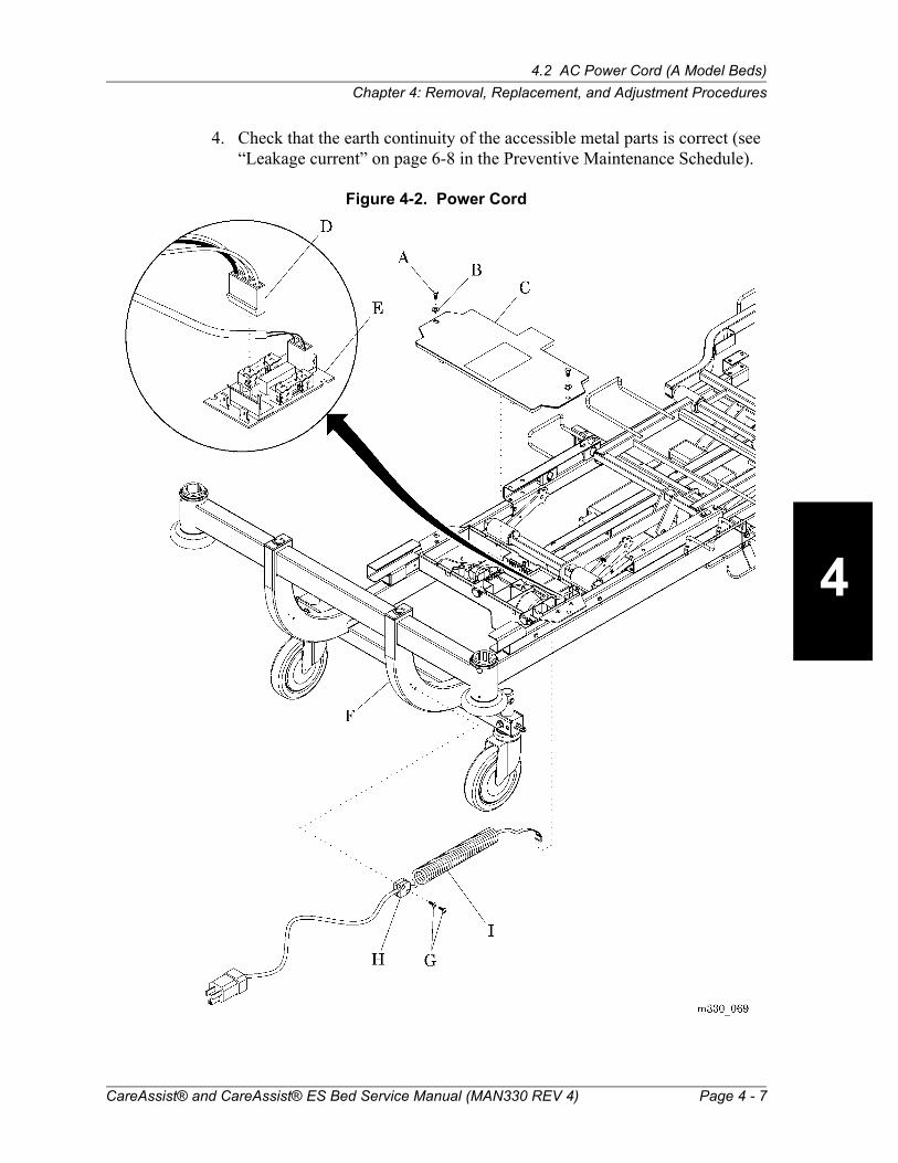
4.2 AC Power Cord (A Model Beds) Chapter 4: Removal, Replacement, and Adjustment Procedures
4. Check that the earth continuity of the accessible metal parts is correct (see “Leakage current” on page 6-8 in the Preventive Maintenance Schedule).
Figure 4-2. Power Cord
4
CareAssist® and CareAssist® ES Bed Service Manual (MAN330 REV 4) Page 4 - 7
4.2 AC Power Cord (A Model Beds) Chapter 4: Removal, Replacement, and Adjustment Procedures
SHOCK HAZARD: An abnormally high leakage current is symptomatic of a degradation within the AC power cable and the power supply. Personal injury could result if the value of the leakage current is above 500 microamperes.
5. Check that the leakage current of the bed is compliant (see “Leakage current” on page 6-8 in the Preventive Maintenance Schedule).
6. To make sure the CareAssist® Bed operates correctly, do the “Function Checks” on page 2-5.
Page 4 - 8 CareAssist® and CareAssist® ES Bed Service Manual (MAN330 REV 4)
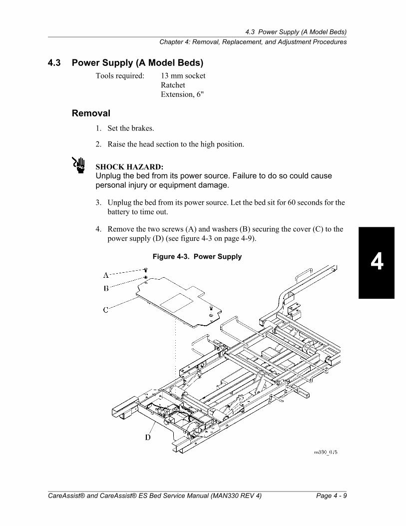
4.3 Power Supply (A Model Beds) Chapter 4: Removal, Replacement, and Adjustment Procedures
4.3 Power Supply (A Model Beds) Tools required: 13 mm socket
Ratchet Extension, 6"
Removal 1. Set the brakes.
2. Raise the head section to the high position.
SHOCK HAZARD: Unplug the bed from its power source. Failure to do so could cause personal injury or equipment damage.
3. Unplug the bed from its power source. Let the bed sit for 60 seconds for the battery to time out.
4. Remove the two screws (A) and washers (B) securing the cover (C) to the power supply (D) (see figure 4-3 on page 4-9).
Figure 4-3. Power Supply 4
CareAssist® and CareAssist® ES Bed Service Manual (MAN330 REV 4) Page 4 - 9
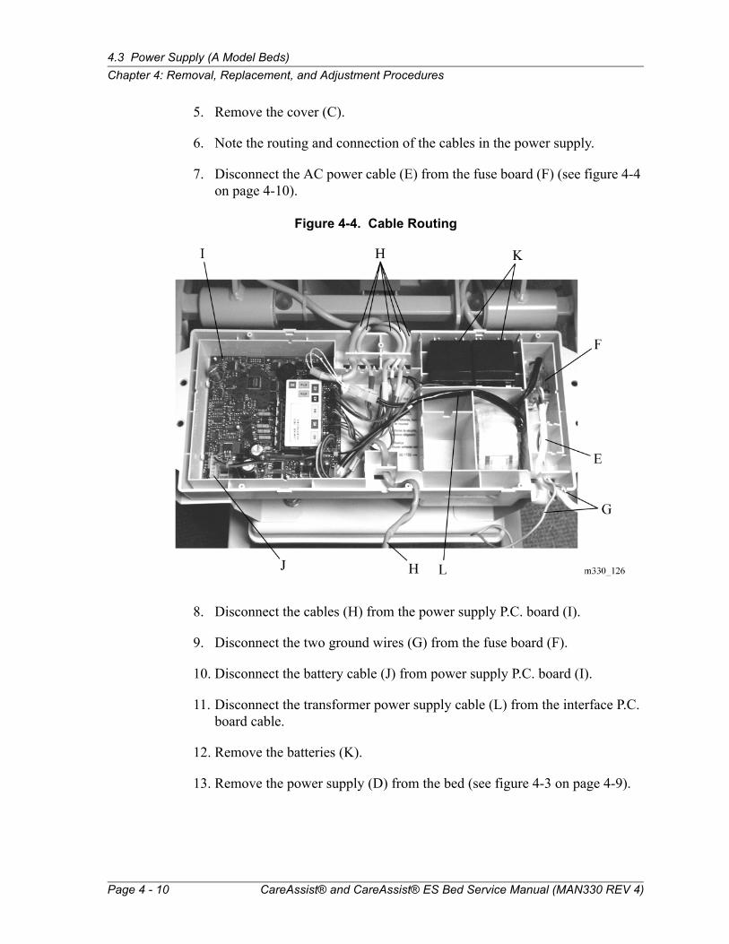
4.3 Power Supply (A Model Beds) Chapter 4: Removal, Replacement, and Adjustment Procedures
5. Remove the cover (C).
6. Note the routing and connection of the cables in the power supply.
7. Disconnect the AC power cable (E) from the fuse board (F) (see figure 4-4 on page 4-10).
Figure 4-4. Cable Routing
8. Disconnect the cables (H) from the power supply P.C. board (I).
9. Disconnect the two ground wires (G) from the fuse board (F).
10. Disconnect the battery cable (J) from power supply P.C. board (I).
11. Disconnect the transformer power supply cable (L) from the interface P.C. board cable.
12. Remove the batteries (K).
13. Remove the power supply (D) from the bed (see figure 4-3 on page 4-9).
Page 4 - 10 CareAssist® and CareAssist® ES Bed Service Manual (MAN330 REV 4)
4.3 Power Supply (A Model Beds) Chapter 4: Removal, Replacement, and Adjustment Procedures
Replacement 1. Do the removal procedures in reverse order. For cable connections, refer to
table 4-1 on page 4-11.
Table 4-1. Power Supply Connections
Connector number Marking Color Identification
0 #0 Red Not used 1a #1a Gray Right hand siderail 1b #1b Gray Left hand siderail 2 #2 Green Foot section motor 3 #3 Blue Head section motor 4 #4 Yellow Foot hilow column 5 #5 Brown Knee section motor 6 #6 Yellow Head hilow column
2. Check the dates shown on the batteries and replace them if they are older than three years.
3. Check that the earth continuity of the accessible metal parts is correct (see “Leakage current” on page 6-8 in the Preventive Maintenance Schedule).
SHOCK HAZARD: An abnormally high leakage current is symptomatic of a degradation within the AC power cable and the power supply. Personal injury could result if the value of the leakage current is above 500 microamperes.
4. Check that the leakage current of the bed is compliant (see “Leakage current” on page 6-8 in the Preventive Maintenance Schedule).
5. To make sure the CareAssist® Bed operates correctly, do the “Function Checks” on page 2-5.
4
CareAssist® and CareAssist® ES Bed Service Manual (MAN330 REV 4) Page 4 - 11
4.4 Battery (A Model Beds) Chapter 4: Removal, Replacement, and Adjustment Procedures
4.4 Battery (A Model Beds) Tools required: 13 mm socket
Ratchet Extension
NOTE: It is required to change both batteries at the same time.
Removal 1. Set the brakes.
2. Raise the head section to the high position.
SHOCK HAZARD: Unplug the bed from its power source. Failure to do so could cause personal injury or equipment damage.
3. Unplug the bed from its power source. Let the bed sit for 60 seconds for the battery to time out.
4. Remove the two screws (A) and washers (B) from the power supply cover (C) (see figure 4-5 on page 4-13).
5. Remove the cover (C).
6. Disconnect the battery cable (D) from the power supply P.C. board (E).
7. Remove the batteries (F).
8. Note the connection of the wires on the batteries.
9. Disconnect the battery cables (D) and (G) from the batteries (F).
Page 4 - 12 CareAssist® and CareAssist® ES Bed Service Manual (MAN330 REV 4)
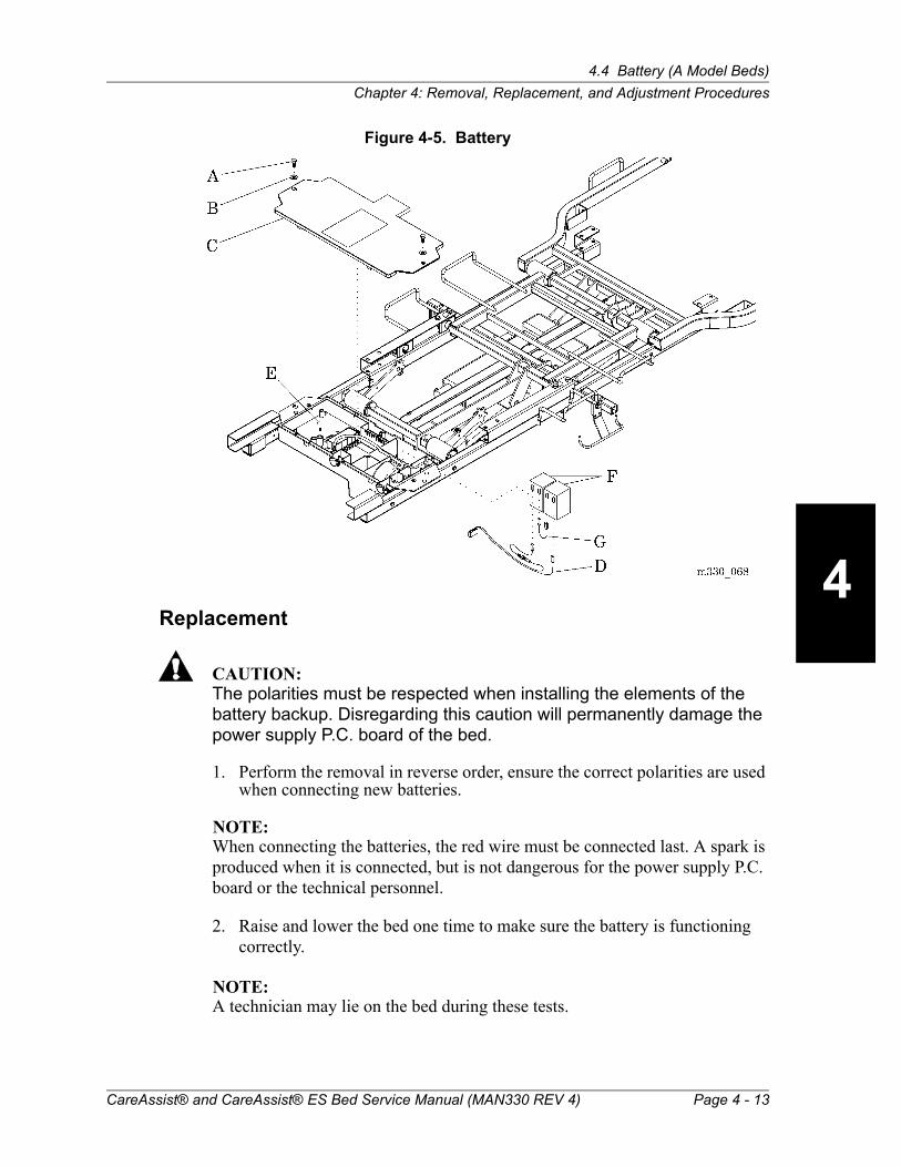
4.4 Battery (A Model Beds) Chapter 4: Removal, Replacement, and Adjustment Procedures
Figure 4-5. Battery
Replacement 4
CAUTION: The polarities must be respected when installing the elements of the battery backup. Disregarding this caution will permanently damage the power supply P.C. board of the bed.
1. Perform the removal in reverse order, ensure the correct polarities are used when connecting new batteries.
NOTE: When connecting the batteries, the red wire must be connected last. A spark is produced when it is connected, but is not dangerous for the power supply P.C. board or the technical personnel.
2. Raise and lower the bed one time to make sure the battery is functioning correctly.
NOTE: A technician may lie on the bed during these tests.
CareAssist® and CareAssist® ES Bed Service Manual (MAN330 REV 4) Page 4 - 13
4.4 Battery (A Model Beds) Chapter 4: Removal, Replacement, and Adjustment Procedures
3. Plug the bed into an appropriate power source.
NOTE: The batteries should be fully recharged at the end of the test or if the low battery signal is heard during the tests.
4. To make sure the CareAssist® Bed operates correctly, do the “Function Checks” on page 2-5.
Page 4 - 14 CareAssist® and CareAssist® ES Bed Service Manual (MAN330 REV 4)
4.5 Head Section Motor Chapter 4: Removal, Replacement, and Adjustment Procedures
4.5 Head Section Motor Tools required: (2) 10 mm wrench
13 mm socket Ratchet T25 Torx®1 screwdriver
Removal 1. Set the brakes.
2. Raise the sleep surface to the highest position.
3. Raise the head section to the highest position.
NOTE: If the head section motor is defective, the CPR control can be used to raise the head section.
SHOCK HAZARD: Unplug the bed from its power source. Failure to do so could cause personal injury or equipment damage.
4. Unplug the bed from its power source. Let the bed sit for 60 seconds so the battery will time out.
5. Remove the headboard.
6. Remove the seat and knee sections.
7. For A model beds, do as follows, otherwise go to step 8:
a. Remove the two screws (A) and washers (B) securing the power supply cover (C) to the power supply (D) (see figure 4-6 on page 4-16).
b. Remove the cover (C).
4
1. Torx® is a registered trademark of Acument Intellectual Properties, LLC.
CareAssist® and CareAssist® ES Bed Service Manual (MAN330 REV 4) Page 4 - 15

4.5 Head Section Motor Chapter 4: Removal, Replacement, and Adjustment Procedures
Figure 4-6. Power Supply
8. For B model beds, do as follows:
a. Remove the two screws (O) from the retainers (Q) (see figure 4-7 on page 4-17).
b. Remove the retainers (Q).
c. Remove the three screws (R) that attach the power supply cover (S) to the power supply (T).
d. Remove the power supply cover (S).
NOTE: The power supply cover is connected to the power supply P.C. board by the battery cable.
e. Disconnect the battery cable from the power supply P.C. board.
f. Remove the power supply cover (S) from the bed.
Page 4 - 16 CareAssist® and CareAssist® ES Bed Service Manual (MAN330 REV 4)
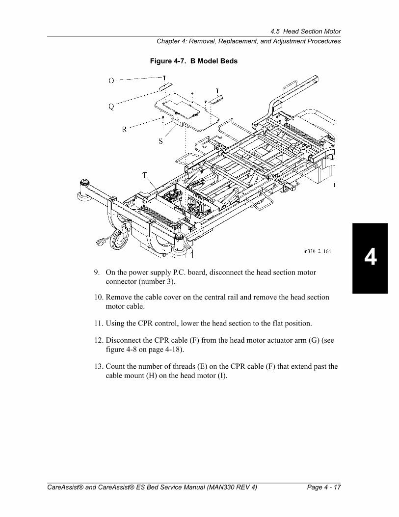
4.5 Head Section Motor Chapter 4: Removal, Replacement, and Adjustment Procedures
Figure 4-7. B Model Beds
9. On the power supply P.C. board, disconnect the head section motor connector (number 3).
10. Remove the cable cover on the central rail and remove the head section motor cable.
11. Using the CPR control, lower the head section to the flat position.
12. Disconnect the CPR cable (F) from the head motor actuator arm (G) (see figure 4-8 on page 4-18).
13. Count the number of threads (E) on the CPR cable (F) that extend past the cable mount (H) on the head motor (I).
4
CareAssist® and CareAssist® ES Bed Service Manual (MAN330 REV 4) Page 4 - 17
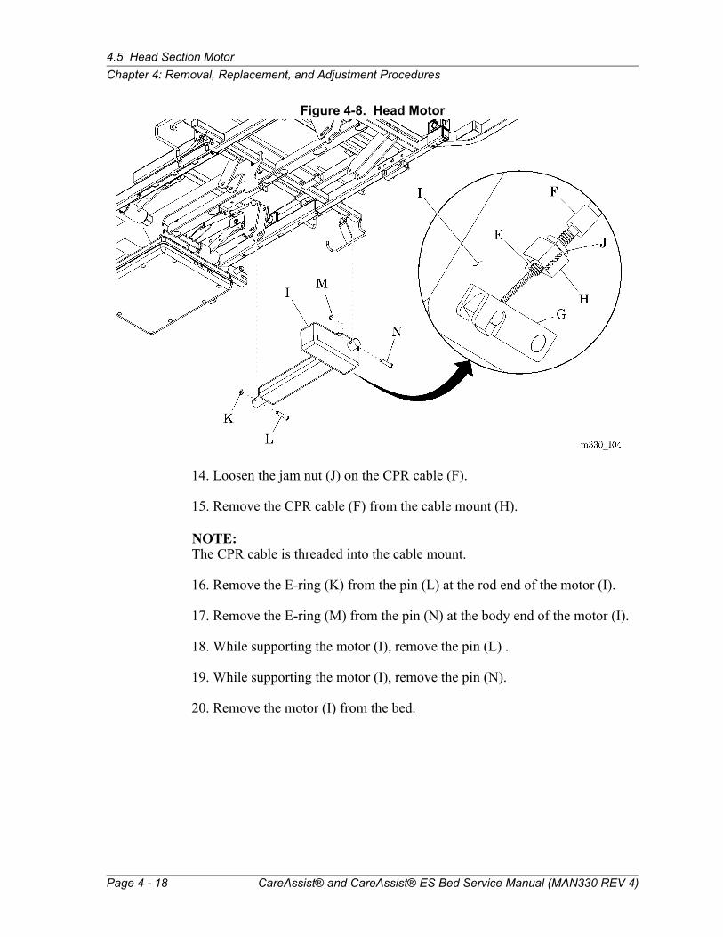
4.5 Head Section Motor Chapter 4: Removal, Replacement, and Adjustment Procedures
Figure 4-8. Head Motor
14. Loosen the jam nut (J) on the CPR cable (F).
15. Remove the CPR cable (F) from the cable mount (H).
NOTE: The CPR cable is threaded into the cable mount.
16. Remove the E-ring (K) from the pin (L) at the rod end of the motor (I).
17. Remove the E-ring (M) from the pin (N) at the body end of the motor (I).
18. While supporting the motor (I), remove the pin (L) .
19. While supporting the motor (I), remove the pin (N).
20. Remove the motor (I) from the bed.
Page 4 - 18 CareAssist® and CareAssist® ES Bed Service Manual (MAN330 REV 4)

4.5 Head Section Motor Chapter 4: Removal, Replacement, and Adjustment Procedures
Replacement
CAUTION: Make sure that the elastic found on the new motors is not wound around the motor body before removing it (cut). If necessary, turn the motor end rod in the appropriate direction to unwind this elastic. It is used to indicate the correct position of the switches and internal end of travels of the motor. The incorrect position of these elements may damage the motor or the structure of the bed.
1. Perform the removal procedure in reverse order.
2. Remove the elastic on the motor.
3. Activate the CPR function. The CPR function should activate when the CPR handle is approximately half way through its travel.
4. Adjust the CPR cable as needed (refer to procedure 4.6).
5. To make sure the CareAssist® Bed operates correctly, do the “Function Checks” on page 2-5.
4
CareAssist® and CareAssist® ES Bed Service Manual (MAN330 REV 4) Page 4 - 19
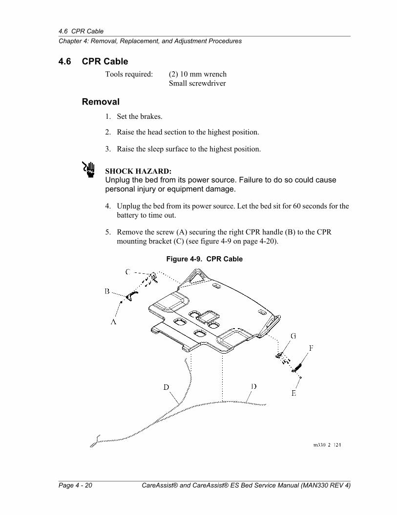
4.6 CPR Cable Chapter 4: Removal, Replacement, and Adjustment Procedures
4.6 CPR Cable Tools required: (2) 10 mm wrench
Small screwdriver
Removal 1. Set the brakes.
2. Raise the head section to the highest position.
3. Raise the sleep surface to the highest position.
SHOCK HAZARD: Unplug the bed from its power source. Failure to do so could cause personal injury or equipment damage.
4. Unplug the bed from its power source. Let the bed sit for 60 seconds for the battery to time out.
5. Remove the screw (A) securing the right CPR handle (B) to the CPR mounting bracket (C) (see figure 4-9 on page 4-20).
Figure 4-9. CPR Cable
Page 4 - 20 CareAssist® and CareAssist® ES Bed Service Manual (MAN330 REV 4)
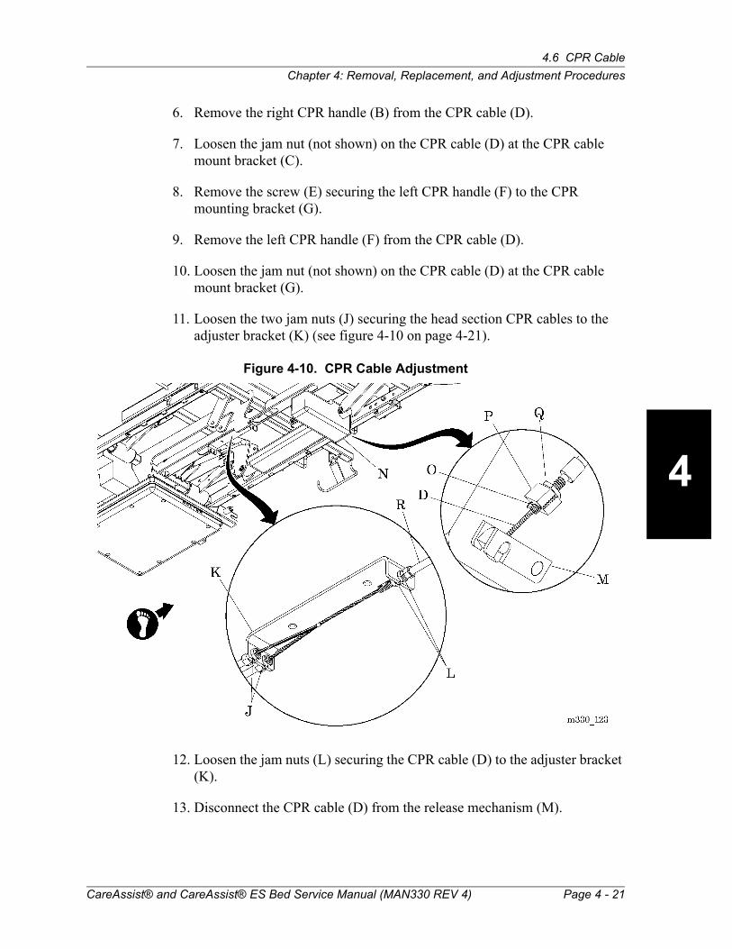
4.6 CPR Cable Chapter 4: Removal, Replacement, and Adjustment Procedures
6. Remove the right CPR handle (B) from the CPR cable (D).
7. Loosen the jam nut (not shown) on the CPR cable (D) at the CPR cable mount bracket (C).
8. Remove the screw (E) securing the left CPR handle (F) to the CPR mounting bracket (G).
9. Remove the left CPR handle (F) from the CPR cable (D).
10. Loosen the jam nut (not shown) on the CPR cable (D) at the CPR cable mount bracket (G).
11. Loosen the two jam nuts (J) securing the head section CPR cables to the adjuster bracket (K) (see figure 4-10 on page 4-21).
Figure 4-10. CPR Cable Adjustment
12. Loosen the jam nuts (L) securing the CPR cable (D) to the adjuster bracket (K).
13. Disconnect the CPR cable (D) from the release mechanism (M).
4
CareAssist® and CareAssist® ES Bed Service Manual (MAN330 REV 4) Page 4 - 21
4.6 CPR Cable Chapter 4: Removal, Replacement, and Adjustment Procedures
14. Count the number of threads (O) on the CPR cable (D) at the CPR cable mount (P).
15. Loosen the jam nut (Q) on the CPR cable (D) on the CPR cable mount (P).
16. Unscrew the CPR cable (D) from the CPR cable mount (P).
17. Remove the CPR cable (D) from the bed.
Replacement
WARNING: Make sure the CPR cable is routed through the head section guide bracket correctly: right side to right handle, left side to left handle. Failure to do so could cause patient injury or equipment damage.
1. Perform the removal procedure in reverse order.
2. Make sure to route through the head section guide bracket correctly, right side to right handle, left side to left handle.
Adjustment 1. To add tension in the cable, loosen the two jam nuts (L) and move the cable
sheath (R) toward the foot end of the bed to the point where the releasemechanism on the head motor begins to move from the neutral position (see figure 4-10 on page 4-21).
2. To relieve tension in the cable, loosen the two jam nuts (L) and move the cable sheath (R) toward the head end of the bed to the point where the release mechanism on the head motor begins to move from the neutral position.
3. Stop at the point where the release mechanism begins to move from the neutral position.
4. Tighten the two jam nuts (L).
5. To make sure the CareAssist® Bed operates correctly, do the “Function Checks” on page 2-5.
Page 4 - 22 CareAssist® and CareAssist® ES Bed Service Manual (MAN330 REV 4)
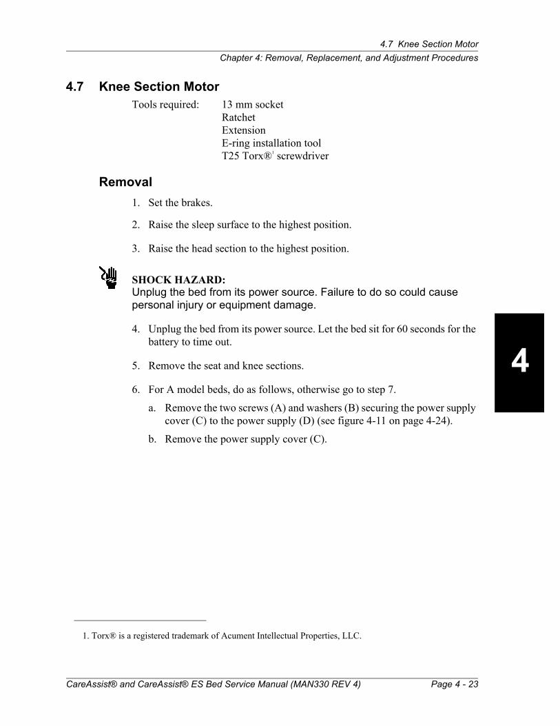
4.7 Knee Section Motor Chapter 4: Removal, Replacement, and Adjustment Procedures
4.7 Knee Section Motor Tools required: 13 mm socket
Ratchet Extension E-ring installation tool T25 Torx®1 screwdriver
Removal 1. Set the brakes.
2. Raise the sleep surface to the highest position.
3. Raise the head section to the highest position.
SHOCK HAZARD: Unplug the bed from its power source. Failure to do so could cause personal injury or equipment damage.
4. Unplug the bed from its power source. Let the bed sit for 60 seconds for the battery to time out.
5. Remove the seat and knee sections.
6. For A model beds, do as follows, otherwise go to step 7.
a. Remove the two screws (A) and washers (B) securing the power supply cover (C) to the power supply (D) (see figure 4-11 on page 4-24).
b. Remove the power supply cover (C).
4
1. Torx® is a registered trademark of Acument Intellectual Properties, LLC.
CareAssist® and CareAssist® ES Bed Service Manual (MAN330 REV 4) Page 4 - 23
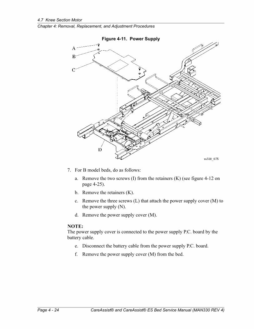
4.7 Knee Section Motor Chapter 4: Removal, Replacement, and Adjustment Procedures
Figure 4-11. Power Supply
7. For B model beds, do as follows:
a. Remove the two screws (I) from the retainers (K) (see figure 4-12 on page 4-25).
b. Remove the retainers (K).
c. Remove the three screws (L) that attach the power supply cover (M) to the power supply (N).
d. Remove the power supply cover (M).
NOTE: The power supply cover is connected to the power supply P.C. board by the battery cable.
e. Disconnect the battery cable from the power supply P.C. board.
f. Remove the power supply cover (M) from the bed.
Page 4 - 24 CareAssist® and CareAssist® ES Bed Service Manual (MAN330 REV 4)
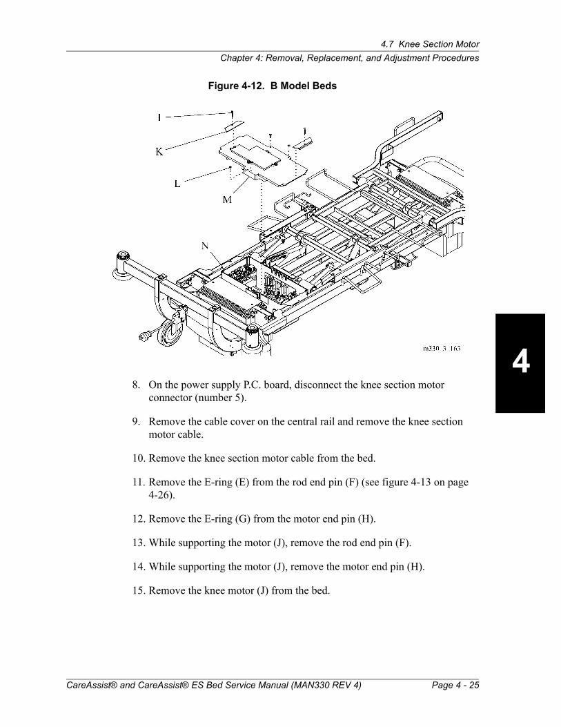
4.7 Knee Section Motor Chapter 4: Removal, Replacement, and Adjustment Procedures
Figure 4-12. B Model Beds
8. On the power supply P.C. board, disconnect the knee section motor connector (number 5).
9. Remove the cable cover on the central rail and remove the knee section motor cable.
10. Remove the knee section motor cable from the bed.
11. Remove the E-ring (E) from the rod end pin (F) (see figure 4-13 on page 4-26).
12. Remove the E-ring (G) from the motor end pin (H).
13. While supporting the motor (J), remove the rod end pin (F).
14. While supporting the motor (J), remove the motor end pin (H).
15. Remove the knee motor (J) from the bed.
4
CareAssist® and CareAssist® ES Bed Service Manual (MAN330 REV 4) Page 4 - 25
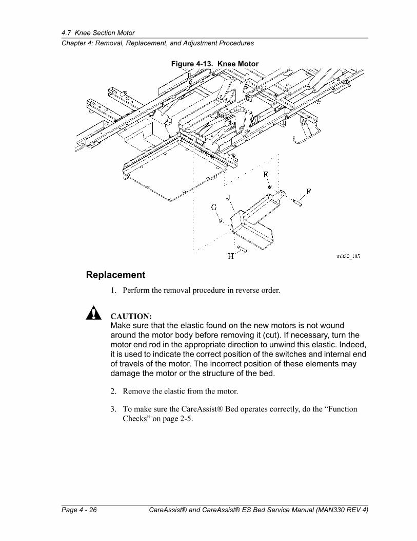
4.7 Knee Section Motor Chapter 4: Removal, Replacement, and Adjustment Procedures
Figure 4-13. Knee Motor
Replacement 1. Perform the removal procedure in reverse order.
CAUTION: Make sure that the elastic found on the new motors is not wound around the motor body before removing it (cut). If necessary, turn the motor end rod in the appropriate direction to unwind this elastic. Indeed, it is used to indicate the correct position of the switches and internal end of travels of the motor. The incorrect position of these elements may damage the motor or the structure of the bed.
2. Remove the elastic from the motor.
3. To make sure the CareAssist® Bed operates correctly, do the “Function Checks” on page 2-5.
Page 4 - 26 CareAssist® and CareAssist® ES Bed Service Manual (MAN330 REV 4)

4.8 Foot Section Motor Chapter 4: Removal, Replacement, and Adjustment Procedures
4.8 Foot Section Motor Tools required: 13 mm socket
Ratchet Extension E-ring installation tool T25 Torx®1 screwdriver
Removal 1. Set the brakes.
2. Raise the sleep surface to the highest position.
3. Raise the head section to the highest position.
4. Remove the seat and knee sections.
SHOCK HAZARD: Unplug the bed from its power source. Failure to do so could cause personal injury or equipment damage.
5. Unplug the bed from its power source. Let the bed sit for 60 seconds for the battery to time out.
6. For A model beds, do as follows, otherwise go to step 7.
a. Remove the two screws (A) and washers (B) securing the power supply cover (C) to the power supply (D) (see figure 4-14 on page 4-28).
b. Remove the power supply cover (C).
4
1. Torx® is a registered trademark of Acument Intellectual Properties, LLC.
CareAssist® and CareAssist® ES Bed Service Manual (MAN330 REV 4) Page 4 - 27
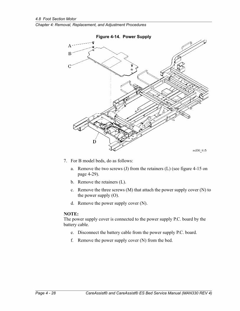
4.8 Foot Section Motor Chapter 4: Removal, Replacement, and Adjustment Procedures
Figure 4-14. Power Supply
7. For B model beds, do as follows:
a. Remove the two screws (J) from the retainers (L) (see figure 4-15 on page 4-29).
b. Remove the retainers (L).
c. Remove the three screws (M) that attach the power supply cover (N) to the power supply (O).
d. Remove the power supply cover (N).
NOTE: The power supply cover is connected to the power supply P.C. board by the battery cable.
e. Disconnect the battery cable from the power supply P.C. board.
f. Remove the power supply cover (N) from the bed.
Page 4 - 28 CareAssist® and CareAssist® ES Bed Service Manual (MAN330 REV 4)

4.8 Foot Section Motor Chapter 4: Removal, Replacement, and Adjustment Procedures
Figure 4-15. B Model Beds
8. On the power supply P.C. board, disconnect the foot section motor connector (number 2).
9. Remove the cable cover on the central rail and remove the foot section motor cable.
10. Remove the foot section motor cable from the bed.
11. Remove the E-ring (E) from the rod end pin (F) (see figure 4-16 on page 4-30).
12. Remove the E-ring (G) from the motor end pin (H).
13. Remove the pin (F) and two plastic spacers (I).
NOTE: Note the position of the plastic spacers for installation later.
14. Remove the motor end pin (H).
4
CareAssist® and CareAssist® ES Bed Service Manual (MAN330 REV 4) Page 4 - 29
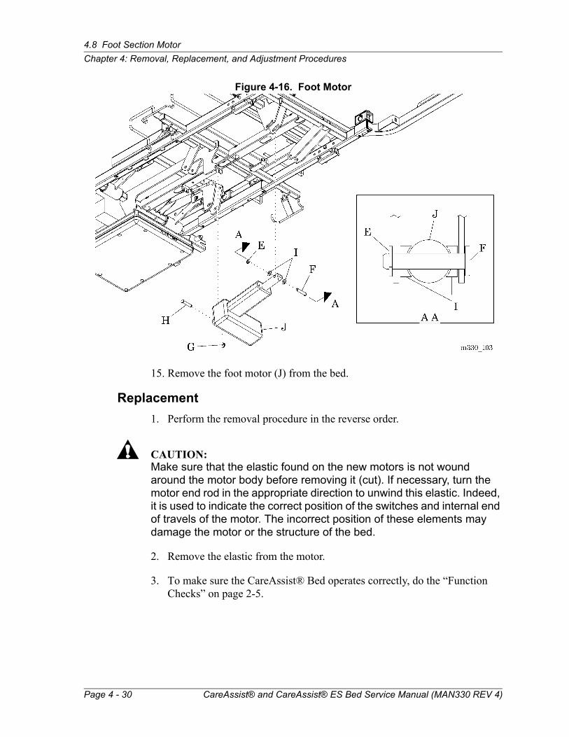
4.8 Foot Section Motor Chapter 4: Removal, Replacement, and Adjustment Procedures
Figure 4-16. Foot Motor
15. Remove the foot motor (J) from the bed.
Replacement 1. Perform the removal procedure in the reverse order.
CAUTION: Make sure that the elastic found on the new motors is not wound around the motor body before removing it (cut). If necessary, turn the motor end rod in the appropriate direction to unwind this elastic. Indeed, it is used to indicate the correct position of the switches and internal end of travels of the motor. The incorrect position of these elements may damage the motor or the structure of the bed.
2. Remove the elastic from the motor.
3. To make sure the CareAssist® Bed operates correctly, do the “Function Checks” on page 2-5.
Page 4 - 30 CareAssist® and CareAssist® ES Bed Service Manual (MAN330 REV 4)
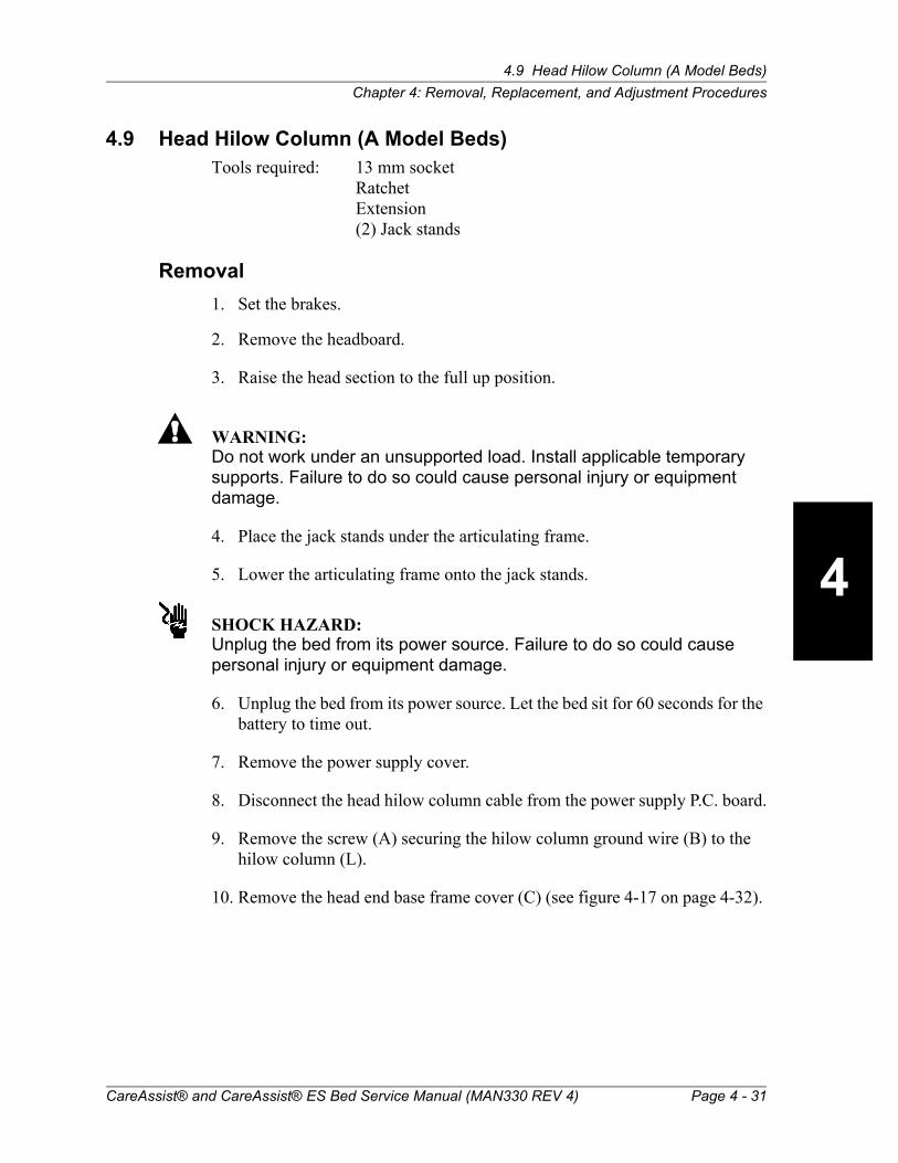
4.9 Head Hilow Column (A Model Beds) Chapter 4: Removal, Replacement, and Adjustment Procedures
4.9 Head Hilow Column (A Model Beds) Tools required: 13 mm socket
Ratchet Extension (2) Jack stands
Removal 1. Set the brakes.
2. Remove the headboard.
3. Raise the head section to the full up position.
WARNING: Do not work under an unsupported load. Install applicable temporary supports. Failure to do so could cause personal injury or equipment damage.
4. Place the jack stands under the articulating frame.
5. Lower the articulating frame onto the jack stands.
SHOCK HAZARD: Unplug the bed from its power source. Failure to do so could cause personal injury or equipment damage.
6. Unplug the bed from its power source. Let the bed sit for 60 seconds for the battery to time out.
7. Remove the power supply cover.
8. Disconnect the head hilow column cable from the power supply P.C. board.
9. Remove the screw (A) securing the hilow column ground wire (B) to the hilow column (L).
10. Remove the head end base frame cover (C) (see figure 4-17 on page 4-32).
4
CareAssist® and CareAssist® ES Bed Service Manual (MAN330 REV 4) Page 4 - 31
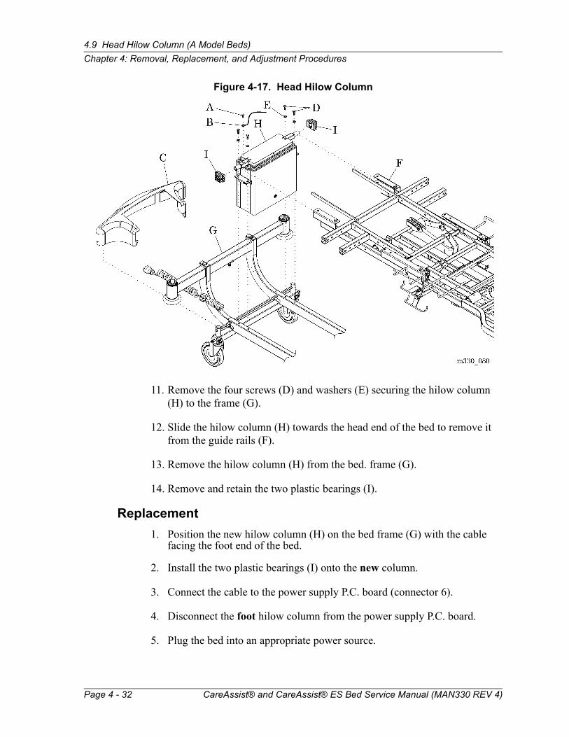
4.9 Head Hilow Column (A Model Beds) Chapter 4: Removal, Replacement, and Adjustment Procedures
Figure 4-17. Head Hilow Column
11. Remove the four screws (D) and washers (E) securing the hilow column (H) to the frame (G).
12. Slide the hilow column (H) towards the head end of the bed to remove it from the guide rails (F).
13. Remove the hilow column (H) from the bed. frame (G).
14. Remove and retain the two plastic bearings (I).
Replacement 1. Position the new hilow column (H) on the bed frame (G) with the cable
facing the foot end of the bed.
2. Install the two plastic bearings (I) onto the new column.
3. Connect the cable to the power supply P.C. board (connector 6).
4. Disconnect the foot hilow column from the power supply P.C. board.
5. Plug the bed into an appropriate power source.
Page 4 - 32 CareAssist® and CareAssist® ES Bed Service Manual (MAN330 REV 4)
4.9 Head Hilow Column (A Model Beds) Chapter 4: Removal, Replacement, and Adjustment Procedures
6. Use the Bed Hilow control, to raise the hilow column to the same height as the bed.
SHOCK HAZARD: Unplug the bed from its power source. Failure to do so could cause personal injury or equipment damage.
7. Unplug the bed from its power source. Let the bed sit for 60 seconds for the battery to time out.
8. Connect the foot hilow column to the power supply P.C. board.
9. Perform the removal procedure in reverse order.
10. Plug the bed into an appropriate power source.
11. Operate the Trendelenburg function to make sure there is no tension on the power supply cable of the column.
SHOCK HAZARD: The equipotential link and the grounding of the metal parts of the bed depend on the correct installation of the earth conductor and grounding spring blades. Personal injury could result if the installation is not correct and/or if the earth continuity is compromised.
12. Check that the earth continuity of the accessible metal parts is correct (see “Leakage current” on page 6-8 in the Preventive Maintenance Schedule).
13. To make sure the CareAssist® Bed operates correctly, do the “Function Checks” on page 2-5.
4
CareAssist® and CareAssist® ES Bed Service Manual (MAN330 REV 4) Page 4 - 33
4.10 Foot Hilow Column (A Model Beds) Chapter 4: Removal, Replacement, and Adjustment Procedures
4.10 Foot Hilow Column (A Model Beds) Tools required: 13 mm socket
Ratchet Extension (2) Jack stands Vise-Grips®1
Removal 1. Set the brakes.
2. Remove the footboard.
3. Raise the head section to the full up position.
4. Remove the seat section of the sleep deck.
5. Remove the thigh section of the sleep deck.
WARNING: Do not work under an unsupported load. Install applicable temporary supports. Failure to do so could cause personal injury or equipment damage.
6. Place the jack stands under the articulating frame.
7. Lower the articulating frame onto the jack stands.
SHOCK HAZARD: Unplug the bed from its power source. Failure to do so could cause personal injury or equipment damage.
8. Unplug the bed from its power source. Let the bed sit for 60 seconds for the battery to time out.
9. Remove the power supply cover.
10. Disconnect the head hilow column cable from the power supply P.C. board.
11. Install the Vise-Grips® into the head hilow channel (see figure 4-18 on page 4-35).
1. Vise-Grip® is a registered trademark of American Tool Companies, Inc.
Page 4 - 34 CareAssist® and CareAssist® ES Bed Service Manual (MAN330 REV 4)
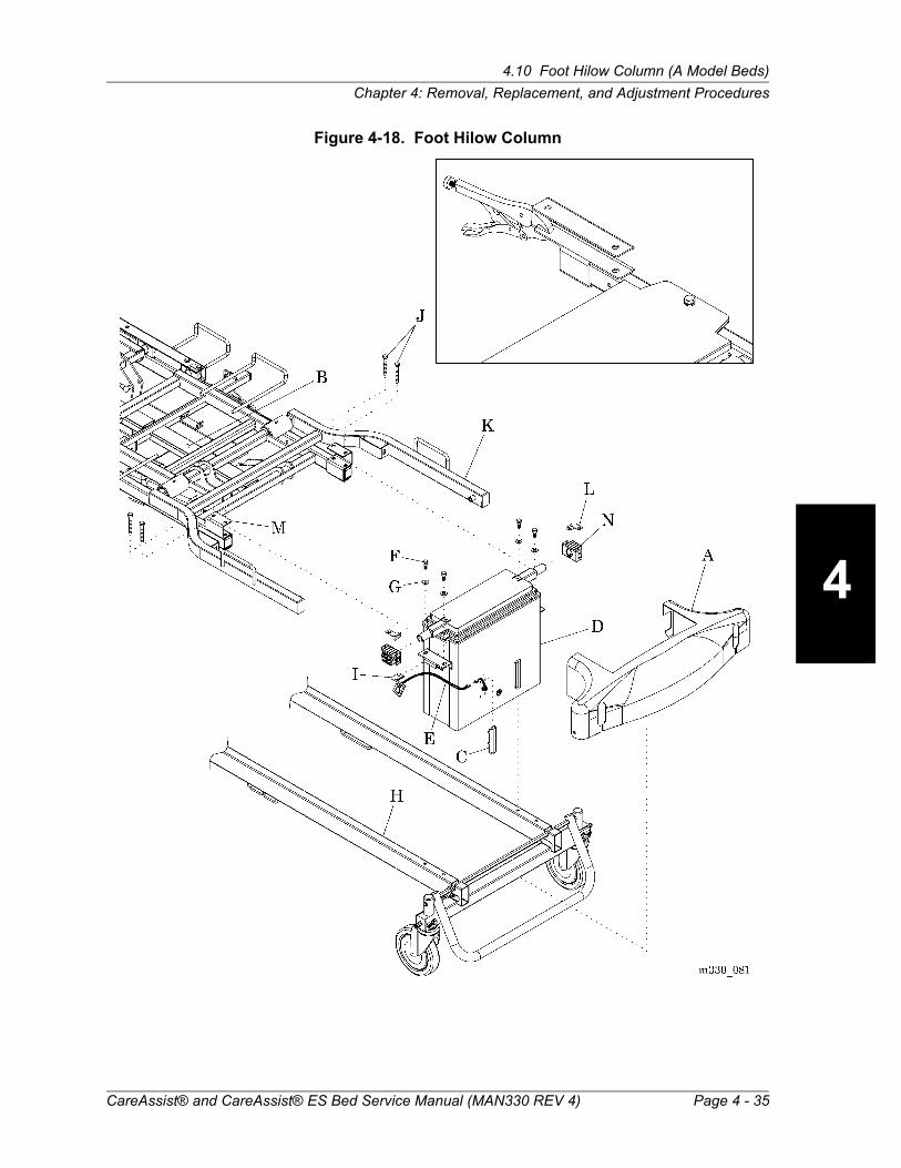
4.10 Foot Hilow Column (A Model Beds) Chapter 4: Removal, Replacement, and Adjustment Procedures
Figure 4-18. Foot Hilow Column
4
CareAssist® and CareAssist® ES Bed Service Manual (MAN330 REV 4) Page 4 - 35
4.10 Foot Hilow Column (A Model Beds) Chapter 4: Removal, Replacement, and Adjustment Procedures
12. Remove the foot frame cover (A).
13. Remove the cable cover (B) from the central rail.
14. Disconnect the foot hilow column cable from the extension cable inside the central rail.
15. Remove the cover (C) from the bottom of the foot hilow column (D).
16. Disconnect the brake detection switch cable (E).
17. Remove the four screws (F) and washers (G) securing the foot hilow column (D) to the bed frame (H).
18. Remove the brake detection switch (I).
19. Remove the four screws (J) securing the hilow column (D) to the articulating frame (K).
20. Remove the grounding plates (L).
21. Tilt the column (D) towards the foot end of the bed.
22. Slide the upper section to remove it from the guide rails (M).
23. Remove the column (D) from the bed.
24. Remove and retain the two plastic bearings (N).
Replacement 1. Position the new column (D) on the bed frame (H) with the two covers (C)
toward the foot end of the bed.
2. Remove the cover (C) on the base of the new column.
3. Route the foot hilow column cable to the central rail.
4. Connect the hilow column cable to the extension cable inside the central rail.
5. Install the two plastic bearings (N) onto the new hilow column (D).
6. Plug the bed into an appropriate power source.
7. Operate the hilow function until the foot hilow column is the same height as the bed.
Page 4 - 36 CareAssist® and CareAssist® ES Bed Service Manual (MAN330 REV 4)
4.10 Foot Hilow Column (A Model Beds) Chapter 4: Removal, Replacement, and Adjustment Procedures
8. Perform the removal procedure in reverse order.
SHOCK HAZARD: The equipotential link and the grounding of the metal parts of the bed depend on the correct installation of the earth conductor and grounding spring blades. Personal injury could result if the installation is not correct and/or if the earth continuity is compromised.
9. Check that the earth continuity of the accessible metal parts is correct (see “Leakage current” on page 6-8 in the Preventive Maintenance Schedule).
10. To make sure the CareAssist® Bed operates correctly, do the “Function Checks” on page 2-5.
4
CareAssist® and CareAssist® ES Bed Service Manual (MAN330 REV 4) Page 4 - 37
4.11 Brake Detection Switch Chapter 4: Removal, Replacement, and Adjustment Procedures
4.11 Brake Detection Switch Tools required: Small screwdriver
13 mm socket Ratchet Extension
Removal 1. Set the brakes.
2. Raise the bed to the highest position.
3. Raise the right, foot end siderail to the up and locked position.
SHOCK HAZARD: Unplug the bed from its power source. Failure to do so could cause personal injury or equipment damage.
4. Unplug the bed from its power source. Let the bed sit for 60 seconds for the battery to time out.
5. Remove the foot frame cover (A) (see figure 4-19 on page 4-39).
6. Remove the cover (B) from the bed right side of the foot hilow column (C).
7. Disconnect the cable (D) from the brake detection switch (F).
8. Open the cable track located under the foot crossbar on the frame, and remove the brake detection switch cable.
9. Remove the screw (E) securing the brake detection switch (F) to the frame.
10. Remove the brake detection switch (F).
Replacement 1. Perform the removal procedure in reverse order.
2. To make sure the CareAssist® Bed operates correctly, do the “Function Checks” on page 2-5.
Page 4 - 38 CareAssist® and CareAssist® ES Bed Service Manual (MAN330 REV 4)
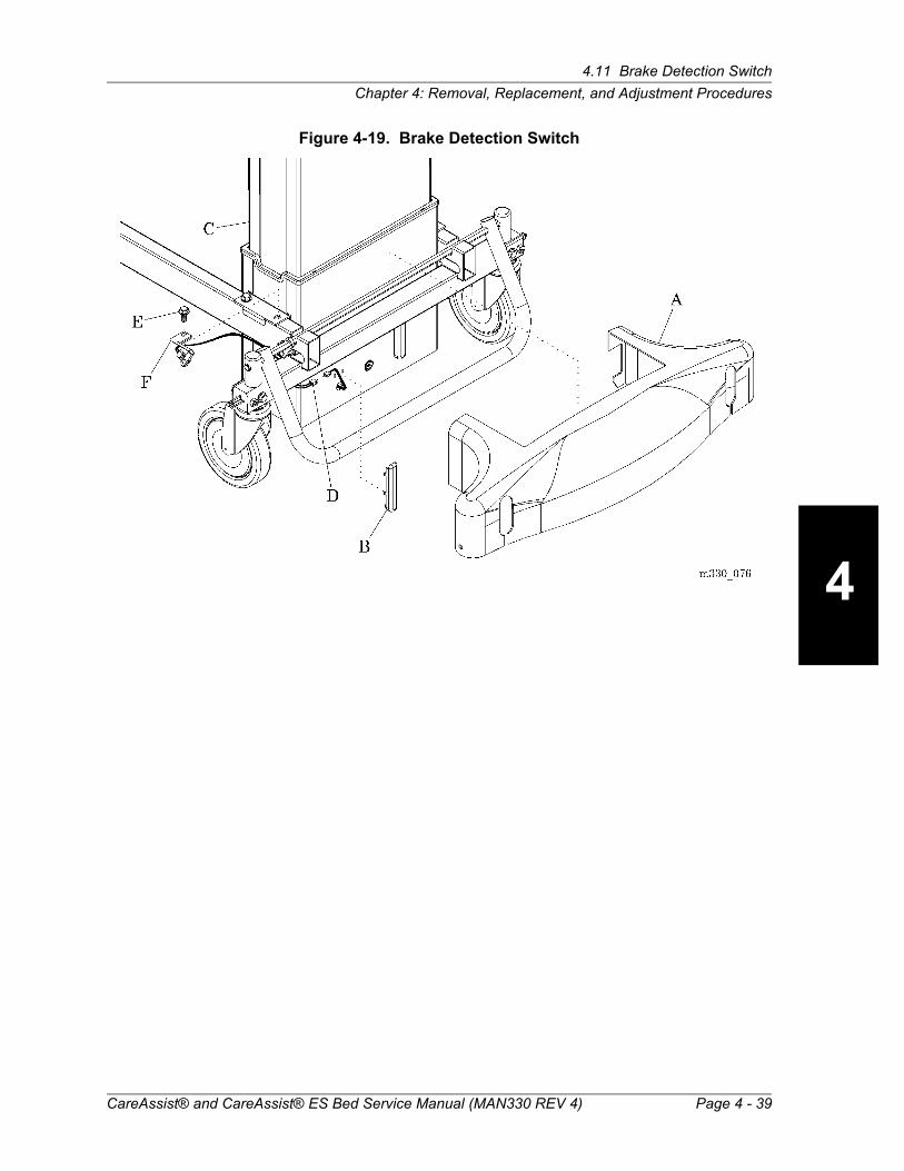
4.11 Brake Detection Switch Chapter 4: Removal, Replacement, and Adjustment Procedures
Figure 4-19. Brake Detection Switch
4
CareAssist® and CareAssist® ES Bed Service Manual (MAN330 REV 4) Page 4 - 39
4.12 Brake/Steer Bar Chapter 4: Removal, Replacement, and Adjustment Procedures
4.12 Brake/Steer Bar Tools required: 13 mm socket
Ratchet Extension 13 mm wrench 10 mm hex key 8 mm pin punch Soft faced hammer (2) 4" x 4" x 2' piece of wood
Removal 1. Set the brakes.
2. Raise the bed to its highest position.
SHOCK HAZARD: Unplug the bed from its power source. Failure to do so could cause personal injury or equipment damage.
3. Unplug the bed from its power source. Let the bed sit for 60 seconds for the battery to time out.
4. Remove the head frame cover.
WARNING: Use correct lifting techniques. Failure to do so can cause personal injury or equipment damage.
5. Using a second person, lift the foot end of the bed and place a piece of wood under the foot hilow column.
6. Using a second person, lift the head end of the bed and place a piece of wood under head the hilow column.
7. Remove the foot frame cover (A) (see figure 4-20 on page 4-41).
8. Remove both right side casters (B) (refer to procedure 4.13).
9. From the left side of the bed, drive the brake bar hex rod (C) out of the left foot caster.
Page 4 - 40 CareAssist® and CareAssist® ES Bed Service Manual (MAN330 REV 4)
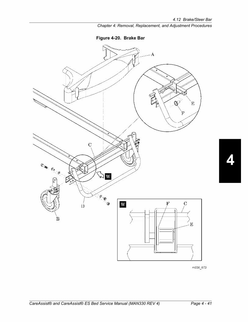
4.12 Brake/Steer Bar Chapter 4: Removal, Replacement, and Adjustment Procedures
Figure 4-20. Brake Bar
4
CareAssist® and CareAssist® ES Bed Service Manual (MAN330 REV 4) Page 4 - 41
4.12 Brake/Steer Bar Chapter 4: Removal, Replacement, and Adjustment Procedures
NOTE: Driving the brake bar hex rod out of the caster will break the white plastic bushing on the right side brake/steer tube.
10. Remove the foot end brake bar (D).
11. From the left side of the bed, drive the brake bar hex rod out of the left head caster.
NOTE: Driving the brake bar hex rod from the caster will break the white plastic bushing on the right side brake/steer tube.
12. Remove the head end brake bar.
13. Remove the brake/steer link bar (E) from the frame.
14. Remove the plastic bushing (F) from the head and foot end brake bars.
Replacement 1. Insert the new bushings (F) into the brake/steer link bar (E).
2. Insert the brake/steer link (E) into the frame.
NOTE: The plastic bushings will be between the brake/steer link bar and the frame.
3. Align the head end brake bar with the bushing in the brake/steer link bar (E).
4. Drive the head end brake bar into the brake/steer link bar (E), seating it inside the bushing.
5. Align the foot end brake bar (D) with the bushing in the brake/steer link bar (E).
6. Drive the foot end brake bar (D) into the brake/steer link bar (E), seating it inside the bushing.
7. Install the casters (B) (refer to procedure 4.13).
8. Install the head and foot frame covers.
Page 4 - 42 CareAssist® and CareAssist® ES Bed Service Manual (MAN330 REV 4)
4.12 Brake/Steer Bar Chapter 4: Removal, Replacement, and Adjustment Procedures
WARNING: Use proper lifting techniques. Failure to do so can cause personal injury or equipment damage.
9. Using a second person, remove the pieces of wood from under the hilow columns.
10. To make sure the CareAssist® Bed operates correctly, do the “Function Checks” on page 2-5.
4
CareAssist® and CareAssist® ES Bed Service Manual (MAN330 REV 4) Page 4 - 43
4.13 Caster Chapter 4: Removal, Replacement, and Adjustment Procedures
4.13 Caster Tools required: 13 mm socket
Ratchet Extension 10 mm hex key Soft faced hammer Medium screwdriver Scissor jack
Removal NOTE: The removal and procedure is the same for both the head and foot end casters.
1. Set the brakes.
2. Raise the bed to the highest position.
SHOCK HAZARD: Unplug the bed from its power source. Failure to do so could cause personal injury or equipment damage.
3. Unplug the bed from its power source. Let the bed sit for 60 seconds for the battery to time out.
4. Depending on the caster to be replaced, remove the head or foot frame cover (A) from the bed (B) (see figure 4-21 on page 4-45).
5. Using the scissor jack, raise the bed high enough to remove the caster .
6. Remove the two alignment bolts (C).
7. Remove the nut (D) and bolt (E).
8. Slide the caster (F) and socket (G) out.
NOTE: When the caster disengages from the brake bar hex rod, it will fall from the socket.
9. Remove the caster (F) from the socket (G).
Page 4 - 44 CareAssist® and CareAssist® ES Bed Service Manual (MAN330 REV 4)
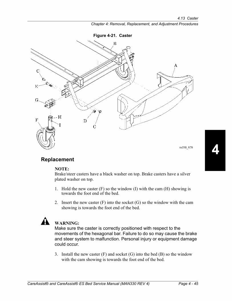
4.13 Caster Chapter 4: Removal, Replacement, and Adjustment Procedures
Figure 4-21. Caster
Replacement NOTE: Brake/steer casters have a black washer on top. Brake casters have a silver plated washer on top.
1. Hold the new caster (F) so the window (I) with the cam (H) showing is towards the foot end of the bed.
2. Insert the new caster (F) into the socket (G) so the window with the cam showing is towards the foot end of the bed.
4
WARNING: Make sure the caster is correctly positioned with respect to the movements of the hexagonal bar. Failure to do so may cause the brake and steer system to malfunction. Personal injury or equipment damage could occur.
3. Install the new caster (F) and socket (G) into the bed (B) so the window with the cam showing is towards the foot end of the bed.
CareAssist® and CareAssist® ES Bed Service Manual (MAN330 REV 4) Page 4 - 45
4.13 Caster Chapter 4: Removal, Replacement, and Adjustment Procedures
4. Install the two alignment bolts (C).
5. Install the bolt (E) and nut (D) through the socket (G).
6. Make sure that the new caster is braked.
7. If the caster is not braked, do as follows:
a. Remove the caster.
b. Rotate the cam inside the caster clockwise until the caster is braked.
c. Install the caster.
d. Make sure the new caster is braked.
e. Repeat as needed.
8. Install the applicable head or foot frame cover (A).
9. To make sure the CareAssist® Bed operates correctly, do the “Function Checks” on page 2-5.
Page 4 - 46 CareAssist® and CareAssist® ES Bed Service Manual (MAN330 REV 4)
4.14 SideCom® Communication System P.C. Board (A Model Beds) Chapter 4: Removal, Replacement, and Adjustment Procedures
4.14 SideCom® Communication System P.C. Board (A Model Beds) Tools required: T15 Torx®1 screwdriver
T25 Torx® screwdriver
Removal 1. Set the brakes.
2. Raise the bed to its highest position.
SHOCK HAZARD: Unplug the bed from its power source. Failure to do so could cause personal injury or equipment damage.
3. Unplug the bed from its power source. Let the bed sit for 60 seconds for the battery to time out.
NOTE: The SideCom® Communication System P.C. board is mounted on the interface box cover.
4. Remove the nine screws (A) securing the interface box cover (B) to the interface box (C) (see figure 4-22 on page 4-48).
5. Lower the box cover (B).
6. Disconnect all cables from the SideCom® Communication System P.C. board (D) and interface P.C. board (E).
7. Remove the six screws (F) securing the interface P.C. board (E) to the box cover (B).
8. Remove the five screws (G) securing the SideCom® Communication System P.C. board (D) to the box cover (B).
9. Remove the SideCom® Communication System P.C. board (D).
4
1. Torx® is a registered trademark of Acument Intellectual Properties, LLC.
CareAssist® and CareAssist® ES Bed Service Manual (MAN330 REV 4) Page 4 - 47
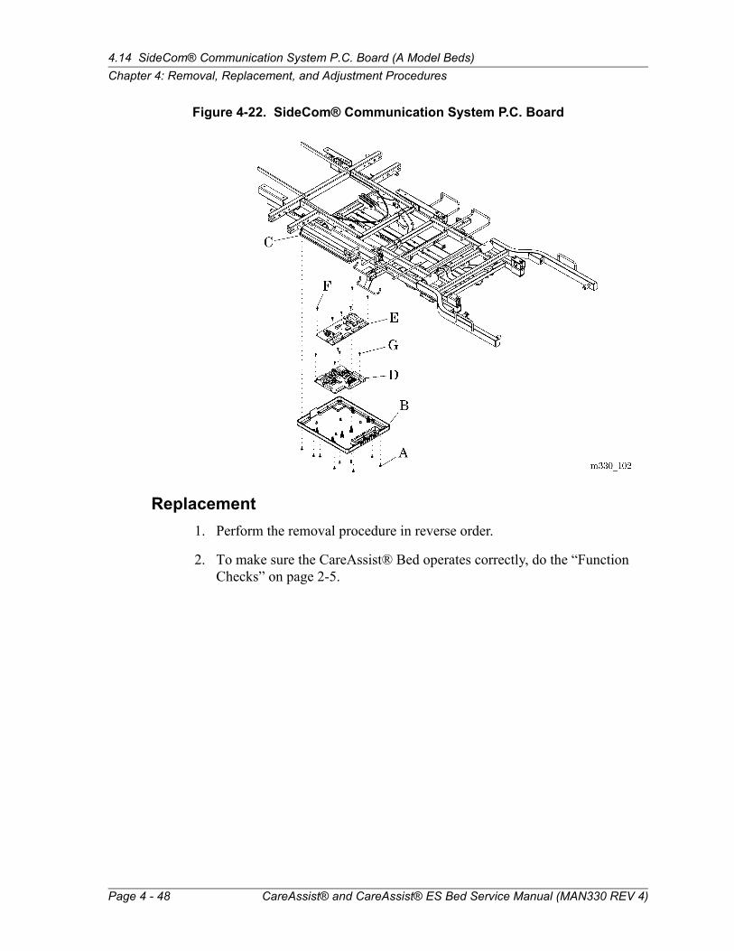
4.14 SideCom® Communication System P.C. Board (A Model Beds) Chapter 4: Removal, Replacement, and Adjustment Procedures
Figure 4-22. SideCom® Communication System P.C. Board
Replacement 1. Perform the removal procedure in reverse order.
2. To make sure the CareAssist® Bed operates correctly, do the “Function Checks” on page 2-5.
Page 4 - 48 CareAssist® and CareAssist® ES Bed Service Manual (MAN330 REV 4)
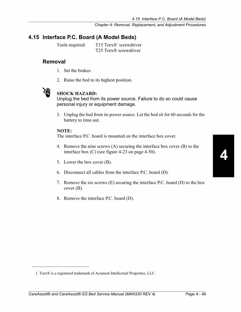
4.15 Interface P.C. Board (A Model Beds) Chapter 4: Removal, Replacement, and Adjustment Procedures
4.15 Interface P.C. Board (A Model Beds) Tools required: T15 Torx®1 screwdriver
T25 Torx® screwdriver
Removal 1. Set the brakes.
2. Raise the bed to its highest position.
SHOCK HAZARD: Unplug the bed from its power source. Failure to do so could cause personal injury or equipment damage.
3. Unplug the bed from its power source. Let the bed sit for 60 seconds for the battery to time out.
NOTE: The interface P.C. board is mounted on the interface box cover.
4. Remove the nine screws (A) securing the interface box cover (B) to the interface box (C) (see figure 4-23 on page 4-50).
5. Lower the box cover (B).
6. Disconnect all cables from the interface P.C. board (D).
7. Remove the six screws (E) securing the interface P.C. board (D) to the box cover (B).
8. Remove the interface P.C. board (D).
4
1. Torx® is a registered trademark of Acument Intellectual Properties, LLC.
CareAssist® and CareAssist® ES Bed Service Manual (MAN330 REV 4) Page 4 - 49
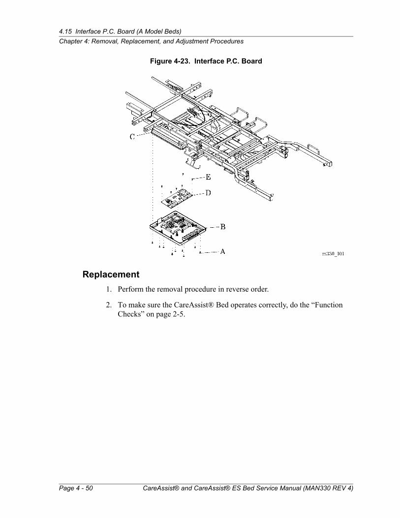
4.15 Interface P.C. Board (A Model Beds) Chapter 4: Removal, Replacement, and Adjustment Procedures
Figure 4-23. Interface P.C. Board
Replacement 1. Perform the removal procedure in reverse order.
2. To make sure the CareAssist® Bed operates correctly, do the “Function Checks” on page 2-5.
Page 4 - 50 CareAssist® and CareAssist® ES Bed Service Manual (MAN330 REV 4)
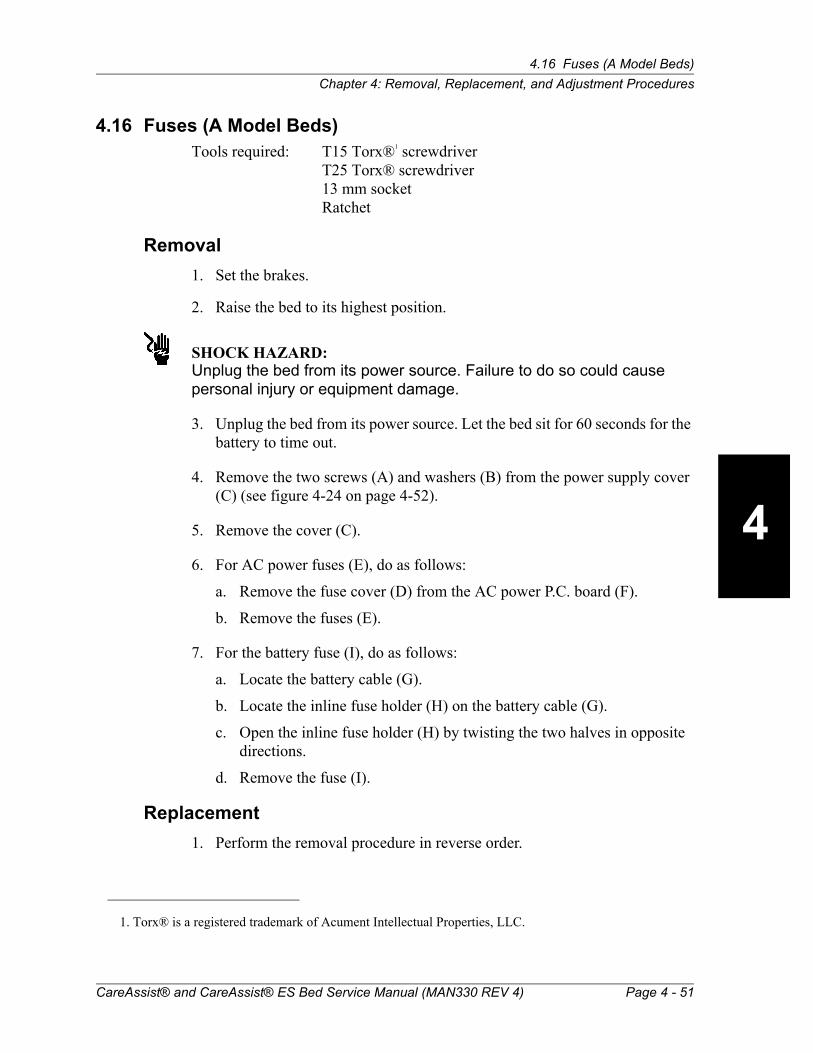
4.16 Fuses (A Model Beds) Chapter 4: Removal, Replacement, and Adjustment Procedures
4.16 Fuses (A Model Beds) Tools required: T15 Torx®1 screwdriver
T25 Torx® screwdriver 13 mm socket Ratchet
Removal 1. Set the brakes.
2. Raise the bed to its highest position.
SHOCK HAZARD: Unplug the bed from its power source. Failure to do so could cause personal injury or equipment damage.
3. Unplug the bed from its power source. Let the bed sit for 60 seconds for the battery to time out.
4. Remove the two screws (A) and washers (B) from the power supply cover (C) (see figure 4-24 on page 4-52).
5. Remove the cover (C).
6. For AC power fuses (E), do as follows:
a. Remove the fuse cover (D) from the AC power P.C. board (F).
b. Remove the fuses (E).
7. For the battery fuse (I), do as follows:
a. Locate the battery cable (G).
b. Locate the inline fuse holder (H) on the battery cable (G).
c. Open the inline fuse holder (H) by twisting the two halves in opposite directions.
d. Remove the fuse (I).
Replacement 1. Perform the removal procedure in reverse order.
1. Torx® is a registered trademark of Acument Intellectual Properties, LLC.
4
CareAssist® and CareAssist® ES Bed Service Manual (MAN330 REV 4) Page 4 - 51
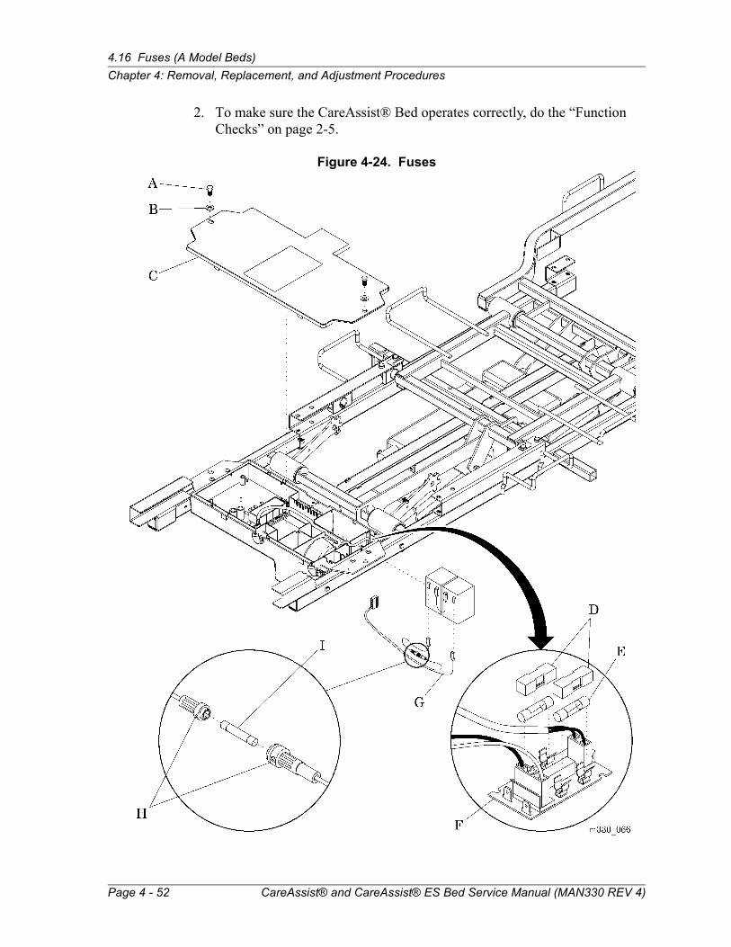
4.16 Fuses (A Model Beds) Chapter 4: Removal, Replacement, and Adjustment Procedures
2. To make sure the CareAssist® Bed operates correctly, do the “Function Checks” on page 2-5.
Figure 4-24. Fuses
Page 4 - 52 CareAssist® and CareAssist® ES Bed Service Manual (MAN330 REV 4)
4.17 Siderail Control P.C. Board Chapter 4: Removal, Replacement, and Adjustment Procedures
4.17 Siderail Control P.C. Board Tools required: T25 Torx®1 screwdriver
T15 Torx® screwdriver Screwdriver Isopropyl alcohol Rags
NOTE: Removing the switch panel from the siderail requires the installation of a new switch panel.
Removal 1. Set the brakes.
2. Raise the bed to its highest position.
3. Raise the siderail to the up and locked position
SHOCK HAZARD: Unplug the bed from its power source. Failure to do so could cause personal injury or equipment damage.
4. Unplug the bed from its power source. Let the bed sit for 60 seconds for the battery to time out.
CAUTION: Use extreme care when removing the switch panel. Failure to do so could cause damage to the seating area of the switch panel on the siderail.
5. Starting on the bottom edge, remove the switch panel (A) from the siderail (B) (see figure 4-25 on page 4-54).
6. Remove the six screws (C) securing the stiffener (D) to the siderail (B).
7. Disconnect the switch panel cable (E) from the siderail control P.C. board (F).
8. Disconnect the siderail cables (G) from the siderail control P.C. board (F).
9. Remove the siderail P.C. board (F) from the stiffener (D).
1. Torx® is a registered trademark of Acument Intellectual Properties, LLC.
4
CareAssist® and CareAssist® ES Bed Service Manual (MAN330 REV 4) Page 4 - 53
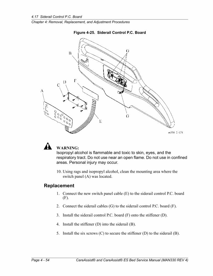
4.17 Siderail Control P.C. Board Chapter 4: Removal, Replacement, and Adjustment Procedures
Figure 4-25. Siderail Control P.C. Board
WARNING: Isopropyl alcohol is flammable and toxic to skin, eyes, and the respiratory tract. Do not use near an open flame. Do not use in confined areas. Personal injury may occur.
10. Using rags and isopropyl alcohol, clean the mounting area where the switch panel (A) was located.
Replacement 1. Connect the new switch panel cable (E) to the siderail control P.C. board
(F).
2. Connect the siderail cables (G) to the siderail control P.C. board (F).
3. Install the siderail control P.C. board (F) onto the stiffener (D).
4. Install the stiffener (D) into the siderail (B).
5. Install the six screws (C) to secure the stiffener (D) to the siderail (B).
Page 4 - 54 CareAssist® and CareAssist® ES Bed Service Manual (MAN330 REV 4)
4.17 Siderail Control P.C. Board Chapter 4: Removal, Replacement, and Adjustment Procedures
6. Remove the wax paper backing from the new switch panel (A).
7. Install the new switch panel (A) onto the siderail (B).
8. To make sure the CareAssist® Bed operates correctly, do the “Function Checks” on page 2-5.
4
CareAssist® and CareAssist® ES Bed Service Manual (MAN330 REV 4) Page 4 - 55
4.18 Patient Pendant Chapter 4: Removal, Replacement, and Adjustment Procedures
4.18 Patient Pendant Tools required: Small blade screwdriver
Removal 1. Set the brakes.
2. Raise the sleep surface to the highest position.
SHOCK HAZARD: Unplug the bed from its power source. Failure to do so could cause personal injury or equipment damage.
3. Unplug the bed from its power source. Let the bed sit for 60 seconds for the battery to time out.
4. Disconnect the pendant cable from pendant mount on the bed.
5. Remove the pendant from the bed.
Replacement 1. Make sure the new pendant has the same functions as the pendant being
replaced.
2. Perform the removal procedure in reverse order.
3. To make sure the CareAssist® Bed operates correctly, do the “Function Checks” on page 2-5.
Page 4 - 56 CareAssist® and CareAssist® ES Bed Service Manual (MAN330 REV 4)
4.19 Patient Pendant Mount Chapter 4: Removal, Replacement, and Adjustment Procedures
4.19 Patient Pendant Mount Tools required: Wire cutters
NOTE: This procedure is for moving the pendant mount from one side of the bed to the other side of the bed.
Removal 1. Set the brakes.
SHOCK HAZARD: Unplug the bed from its power source. Failure to do so could cause personal injury or equipment damage.
2. Unplug the bed from its power source. Let the bed sit for 60 seconds for the battery to time out.
3. Remove the pendant (refer to procedure 4.18).
4. Cut and remove the cable ties securing the pendant mount to the bed.
Replacement 1. Move the pendant mount to the opposite side of the bed.
2. Using cable ties, secure the pendant mount to the bed.
3. To make sure the CareAssist® Bed operates correctly, do the “Function Checks” on page 2-5.
4
CareAssist® and CareAssist® ES Bed Service Manual (MAN330 REV 4) Page 4 - 57
4.20 Bed Exit Switch Chapter 4: Removal, Replacement, and Adjustment Procedures
4.20 Bed Exit Switch Tools required: Soft faced hammer
3/32" punch T25 Torx®1 screwdriver 13 mm wrench
Removal NOTE: The tape switch assembly consists of two tape switches connected to a single cable, if one tape switch is inoperable, both tape switches must be replaced.
1. Set the brakes.
2. Raise the sleep surface to a comfortable working level.
3. Raise the head section to the highest position.
SHOCK HAZARD: Unplug the bed from its power source. Failure to do so could cause personal injury or equipment damage.
4. Unplug the bed from its power source. Let the bed sit for 60 seconds for the battery to time out.
5. Lower the right side siderails.
6. Using the punch, punch out the center of the four rivets (A) securing the switch (B) to the seat section (C) (see figure 4-26 on page 4-59).
7. Remove the switch (B).
8. Using the punch, punch out the center of the four rivets (A) securing the switch (B) to the thigh section (D).
9. Remove the switch (B).
10. Remove the seat section (C) and knee section (D).
11. Remove the two cable covers (E) from the central rail.
1. Torx® is a registered trademark of Acument Intellectual Properties, LLC.
Page 4 - 58 CareAssist® and CareAssist® ES Bed Service Manual (MAN330 REV 4)
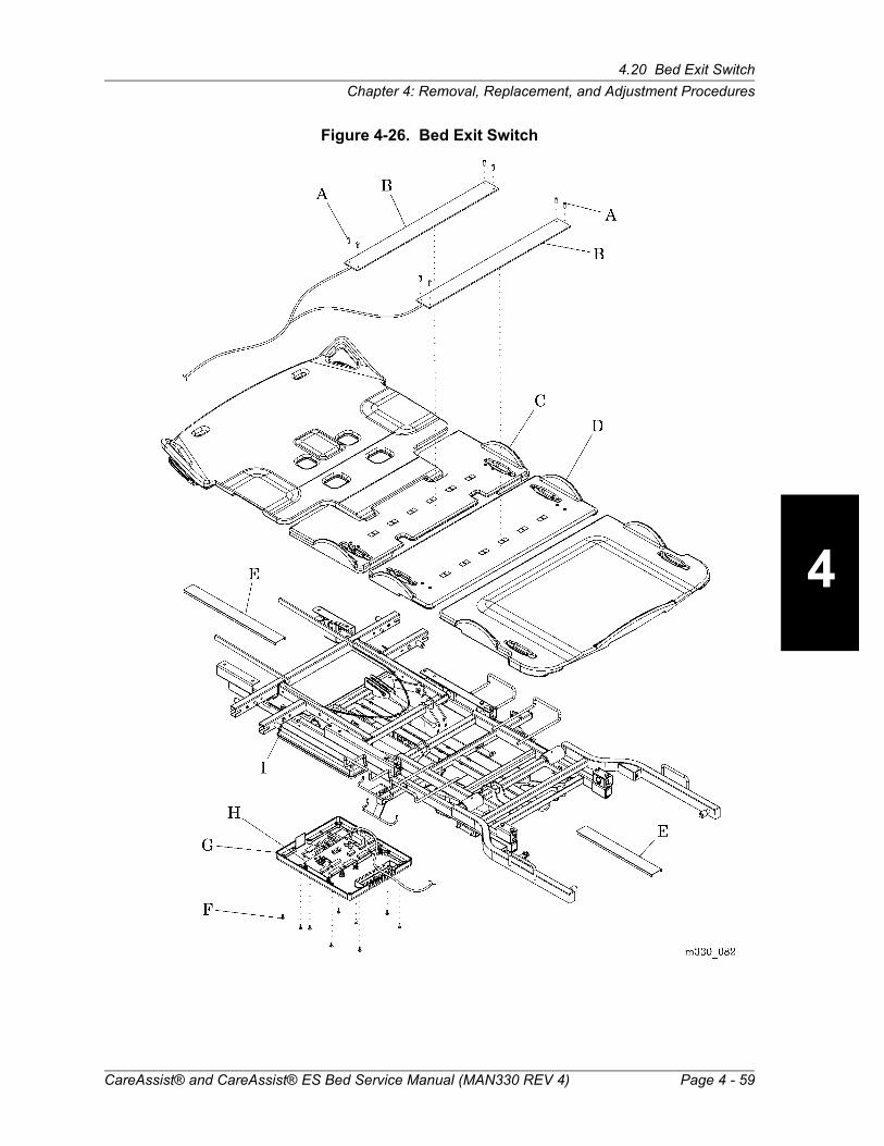
4.20 Bed Exit Switch Chapter 4: Removal, Replacement, and Adjustment Procedures
Figure 4-26. Bed Exit Switch
4
CareAssist® and CareAssist® ES Bed Service Manual (MAN330 REV 4) Page 4 - 59
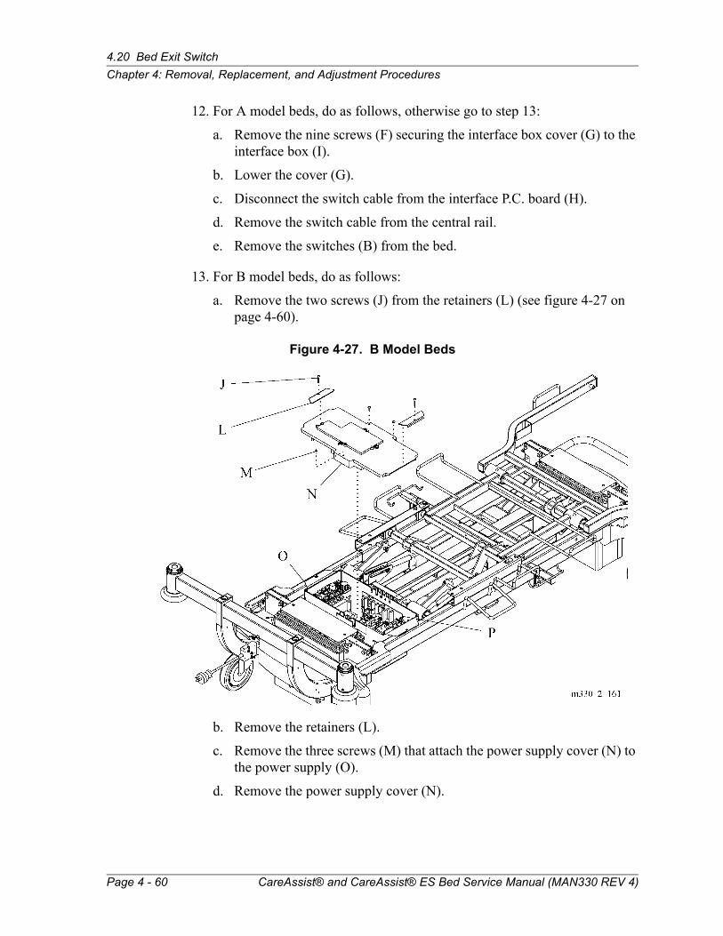
4.20 Bed Exit Switch Chapter 4: Removal, Replacement, and Adjustment Procedures
12. For A model beds, do as follows, otherwise go to step 13:
a. Remove the nine screws (F) securing the interface box cover (G) to the interface box (I).
b. Lower the cover (G).
c. Disconnect the switch cable from the interface P.C. board (H).
d. Remove the switch cable from the central rail.
e. Remove the switches (B) from the bed.
13. For B model beds, do as follows:
a. Remove the two screws (J) from the retainers (L) (see figure 4-27 on page 4-60).
Figure 4-27. B Model Beds
b. Remove the retainers (L).
c. Remove the three screws (M) that attach the power supply cover (N) to the power supply (O).
d. Remove the power supply cover (N).
Page 4 - 60 CareAssist® and CareAssist® ES Bed Service Manual (MAN330 REV 4)
4.20 Bed Exit Switch Chapter 4: Removal, Replacement, and Adjustment Procedures
NOTE: The power supply cover is connected to the power supply P.C. board by the battery cable.
e. Disconnect the battery cable from the power supply P.C. board.
f. Remove the power supply cover (N) from the bed.
g. Disconnect the switch cable from the interface P.C. board (P).
Replacement NOTE: The tape switch assembly consists of two tape switches connected to a single cable that connects to the interface P.C. board.
1. Route the switch cable through the central rail toward the head end of the bed to the interface box (A model beds) or power supply (B Model andNewer Beds).
2. For A model beds, do as follows, otherwise go to step 3:
a. Connect the switch cable to connector P13 on the interface P.C. board (H) (see figure 4-26 on page 4-59).
b. Install the nine screws (F), to secure the interface box cover (G) to the interface box (I).
3. For B model beds, do as follows:
a. Connect the switch cable to connector P13 on the interface P.C. board (P) (see figure 4-27 on page 4-60).
b. Put the power supply cover (N) on the power supply (O).
c. Connect the battery cable to the power supply P.C. board.
d. Install the cover (N) on the power supply (O).
e. Install the three screws (M) to attach the cover (N) to the power supply (O).
f. Install the retainers (L) on the cover (N).
g. Install the two screws (J) and washers (K) to attach the retainers (L to the power supply (O).
4. Lay one switch (B) on the seat section (C) (see figure 4-26 on page 4-59).
5. Install four plastic rivets (A) to secure the switch (B) to the seat section (C).
6. Lay the other switch (B) on the knee section (D).
4
CareAssist® and CareAssist® ES Bed Service Manual (MAN330 REV 4) Page 4 - 61
4.20 Bed Exit Switch Chapter 4: Removal, Replacement, and Adjustment Procedures
7. Install four plastic rivets (A) to secure the switch (B) to the knee section (D).
8. Do the “Function Checks” on page 2-5.
Page 4 - 62 CareAssist® and CareAssist® ES Bed Service Manual (MAN330 REV 4)
4.21 Head Hilow Column (B Model and Newer Beds) Chapter 4: Removal, Replacement, and Adjustment Procedures
4.21 Head Hilow Column (B Model and Newer Beds) Tools required: 13 mm socket
Ratchet Extension (2) Jack stands T25 Torx®1 screwdriver T15 Torx® screwdriver Wire cutters Antistatic strap
Removal 1. Set the brakes.
2. Remove the headboard.
3. Raise the head section to the full up position.
WARNING: Do not work under an unsupported load. Install appropriate supports. Failure to do so could cause personal injury or equipment damage.
4. Place the jack stands under the articulating frame.
5. Lower the articulating frame onto the jack stands.
SHOCK HAZARD: Unplug the bed from its power source. Failure to do so could cause personal injury or equipment damage.
6. Unplug the bed from its power source. Let the bed sit for 60 seconds for the battery to time out.
7. Remove the two screws (A) from the retainers (C) (see figure 4-28 on page 4-64).
8. Remove the retainers (C).
9. Remove the three screws (D) that attach the power supply cover (E) to the power supply (F).
10. Remove the power supply cover (E).
1. Torx® is a registered trademark of Acument Intellectual Properties, LLC.
4
CareAssist® and CareAssist® ES Bed Service Manual (MAN330 REV 4) Page 4 - 63
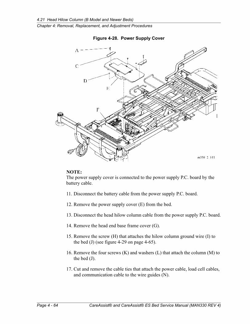
4.21 Head Hilow Column (B Model and Newer Beds) Chapter 4: Removal, Replacement, and Adjustment Procedures
Figure 4-28. Power Supply Cover
NOTE: The power supply cover is connected to the power supply P.C. board by the battery cable.
11. Disconnect the battery cable from the power supply P.C. board.
12. Remove the power supply cover (E) from the bed.
13. Disconnect the head hilow column cable from the power supply P.C. board.
14. Remove the head end base frame cover (G).
15. Remove the screw (H) that attaches the hilow column ground wire (I) to the bed (J) (see figure 4-29 on page 4-65).
16. Remove the four screws (K) and washers (L) that attach the column (M) to the bed (J).
17. Cut and remove the cable ties that attach the power cable, load cell cables, and communication cable to the wire guides (N).
Page 4 - 64 CareAssist® and CareAssist® ES Bed Service Manual (MAN330 REV 4)
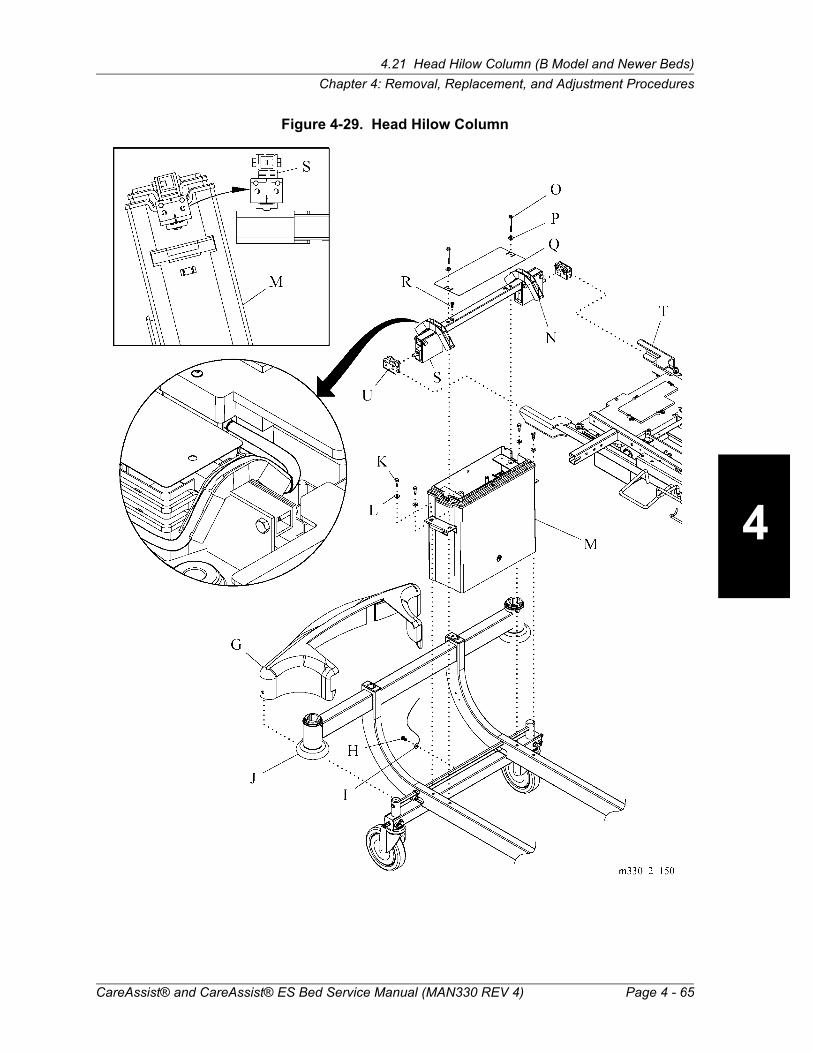
4.21 Head Hilow Column (B Model and Newer Beds) Chapter 4: Removal, Replacement, and Adjustment Procedures
Figure 4-29. Head Hilow Column
4
CareAssist® and CareAssist® ES Bed Service Manual (MAN330 REV 4) Page 4 - 65
4.21 Head Hilow Column (B Model and Newer Beds) Chapter 4: Removal, Replacement, and Adjustment Procedures
18. Remove the two screws (O) and washers (P) from the column cover (Q).
19. Remove the column cover (Q).
20. Remove the screw (R) from the load cell bracket (S).
21. Move the column (M) towards the head end of the bed until the load cell bracket (S) is clear of the weigh frame (T).
22. Remove the load cell bracket (S) and rollers (U) from the column (M).
23. Put the load cell bracket (S) and rollers (U) on the weigh frame (T).
24. Remove the column (M) from the bed (J).
Replacement 1. Put the new hilow column (M) in position on the bed (J). Make sure the
power cable towards the left side of the bed (J).
2. Connect the cable to the power supply P.C. board (connector 6).
3. Disconnect the foot hilow column from the power supply P.C. board.
4. Plug the bed into an appropriate power source.
5. Use the Bed Hilow control to raise the hilow column to the same height as the bed.
SHOCK HAZARD: Unplug the bed from its power source. Failure to do so could cause personal injury or equipment damage.
6. Unplug the bed from its power source. Let the bed sit for 60 seconds for the battery to time out.
7. Connect the foot hilow column to the power supply P.C. board.
8. Put the mark on the power cord and communication cable so the edges of the marks are even with the edge of the wire guide.
9. Put the load cell cables along the side of the power cord and communication cable.
10. Perform the Removal procedure in reverse order.
Page 4 - 66 CareAssist® and CareAssist® ES Bed Service Manual (MAN330 REV 4)
4.21 Head Hilow Column (B Model and Newer Beds) Chapter 4: Removal, Replacement, and Adjustment Procedures
11. Plug the bed into an appropriate power source.
12. Operate the Trendelenburg function to make sure there is no tension in the cables on the column.
13. Do the “Function Checks” on page 2-5.
4
CareAssist® and CareAssist® ES Bed Service Manual (MAN330 REV 4) Page 4 - 67
4.22 Foot Hilow Column (B Model and Newer Beds) Chapter 4: Removal, Replacement, and Adjustment Procedures
4.22 Foot Hilow Column (B Model and Newer Beds) Tools required: 13 mm socket Ratchet
Extension (2) Jack stands T25 Torx®1 screwdriver T15 Torx® screwdriver Wire cutters Antistatic strap Vise-Grips®2 Marking pen String, 10' (305 cm)
Removal 1. Set the brakes.
2. Remove the footboard.
3. Raise the head section to the full up position.
4. Remove the seat section of the sleep deck.
5. Remove the thigh section of the sleep deck.
WARNING: Do not work under an unsupported load. Install appropriate supports. Failure to do so could cause personal injury or equipment damage.
6. Place the jack stands under the articulating frame.
7. Lower the articulating frame onto the jack stands.
SHOCK HAZARD: Unplug the bed from its power source. Failure to do so could cause personal injury or equipment damage.
8. Unplug the bed from its power source. Let the bed sit for 60 seconds for the battery to time out.
9. Remove the two screws (A) from the retainers (C) (see figure 4-30 on page 4-69).
10. Remove the retainers (C).
1. Torx® is a registered trademark of Acument Intellectual Properties, LLC. 2. Vise-Grip® is a registered trademark of American Tool Companies, Inc.
Page 4 - 68 CareAssist® and CareAssist® ES Bed Service Manual (MAN330 REV 4)
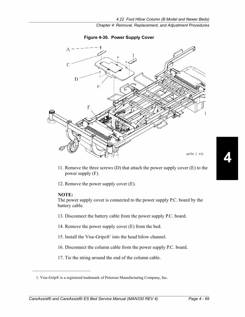
4.22 Foot Hilow Column (B Model and Newer Beds) Chapter 4: Removal, Replacement, and Adjustment Procedures
Figure 4-30. Power Supply Cover
11. Remove the three screws (D) that attach the power supply cover (E) to the power supply (F).
12. Remove the power supply cover (E).
NOTE: The power supply cover is connected to the power supply P.C. board by the battery cable.
13. Disconnect the battery cable from the power supply P.C. board.
14. Remove the power supply cover (E) from the bed.
15. Install the Vise-Grips®1 into the head hilow channel.
16. Disconnect the column cable from the power supply P.C. board.
17. Tie the string around the end of the column cable.
1. Vise-Grip® is a registered trademark of Petersen Manufacturing Company, Inc.
4
CareAssist® and CareAssist® ES Bed Service Manual (MAN330 REV 4) Page 4 - 69
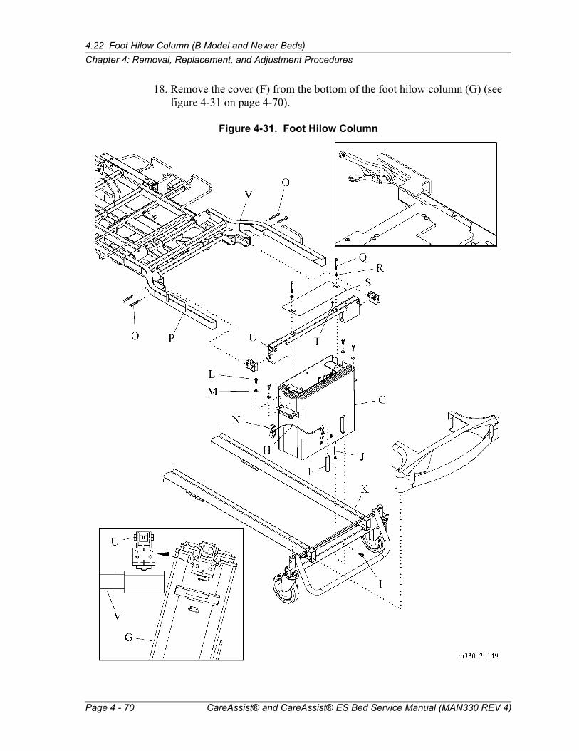
4.22 Foot Hilow Column (B Model and Newer Beds) Chapter 4: Removal, Replacement, and Adjustment Procedures
18. Remove the cover (F) from the bottom of the foot hilow column (G) (see figure 4-31 on page 4-70).
Figure 4-31. Foot Hilow Column
Page 4 - 70 CareAssist® and CareAssist® ES Bed Service Manual (MAN330 REV 4)
4.22 Foot Hilow Column (B Model and Newer Beds) Chapter 4: Removal, Replacement, and Adjustment Procedures
19. Disconnect the brake detection switch cable (H).
20. Remove the screw (I) that attaches the hilow column ground wire (J) to the bed (K).
21. Remove the four screws (L) and washers (M) that attach the foot hilow column (G) to the bed (K).
22. Remove the brake detection switch (N).
23. Remove the four screws (O) that attach the foot hilow column (G) to the weigh frame (P).
24. Remove the two screws (Q) and washers (R) that attach the column cover (S) to the foot hilow column (G).
25. Remove the cover (S).
26. Remove the screw (T) from the load cell bracket (U).
27. Mark the locations of where the cable ties, load cell cables, and the column power cable attach to the bed.
28. Cut and remove the cable ties that attach the load cell cables to the weigh frame (V).
29. Move the column (G) towards the foot end of the bed (K) until the load cell bracket (U) is clear of the weigh frame (V).
30. Remove the load cell bracket (U) from the column (G).
31. Put the load cell bracket on top of the weigh frame (U).
32. Remove the column (G) from the bed (K).
Replacement 1. Put the new foot hilow column (G) in position on the bed (K). Make sure
the two covers (F) are toward the foot end of the bed.
2. Remove the cover (F) on the base of the new column (G).
3. Run the foot hilow column cable to the central rail.
4. Tie the string around the column cable.
5. Pull the string so the column cable goes to the power supply.
4
CareAssist® and CareAssist® ES Bed Service Manual (MAN330 REV 4) Page 4 - 71
4.22 Foot Hilow Column (B Model and Newer Beds) Chapter 4: Removal, Replacement, and Adjustment Procedures
6. Run the column cable to the power supply P.C. board.
7. Connect the column cable to the power supply P.C. board.
8. Disconnect the head hilow column from the power supply P.C. board.
9. Plug the bed into an appropriate power source.
10. Use the Bed Hilow control, to raise the hilow column to the same height as the bed.
SHOCK HAZARD: Unplug the bed from its power source. Failure to do so could cause personal injury or equipment damage.
11. Unplug the bed from its power source. Let the bed sit for 60 seconds for the battery to time out.
12. Connect the head hilow column to the power supply P.C. board.
13. Perform the Removal procedure in reverse order.
14. Plug the bed into an appropriate power source.
15. Operate the Trendelenburg function to make sure there is no tension in the cables on the column.
16. Do the “Function Checks” on page 2-5.
Page 4 - 72 CareAssist® and CareAssist® ES Bed Service Manual (MAN330 REV 4)
4.23 Load Beams (B Model and Newer Beds) Chapter 4: Removal, Replacement, and Adjustment Procedures
4.23 Load Beams (B Model and Newer Beds) Tools required: 13 mm socket
Ratchet (2) Jack stands T15 Torx®1 screwdriver Wire cutters Antistatic strap String, 10' (305 cm)
NOTE: The load cell bracket assembly must be changed as an assembly. The individual load cells are not replaceable.
Removal 1. Set the brakes.
2. Remove the headboard.
3. Raise the head section to the full up position.
4. For foot end load beams, do as follows, otherwise go to step 5:
a. Remove the foot and seat sections of the sleep deck.
b. Remove the central channel cover.
c. Mark the location of the cable ties and load cell cables attach to the bed.
WARNING: Do not work under an unsupported load. Install appropriate supports. Failure to do so could cause personal injury or equipment damage.
5. Place the jack stands under the articulating frame near the load cells being replaced.
6. Remove the two screws (A) and washers (B) that attach the column cover (C) to the column (D) (see figure 4-32 on page 4-74).
7. Remove the column cover (C).
4
1. Torx® is a registered trademark of Acument Intellectual Properties, LLC.
CareAssist® and CareAssist® ES Bed Service Manual (MAN330 REV 4) Page 4 - 73
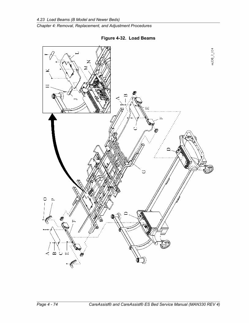
4.23 Load Beams (B Model and Newer Beds) Chapter 4: Removal, Replacement, and Adjustment Procedures
Figure 4-32. Load Beams
Page 4 - 74 CareAssist® and CareAssist® ES Bed Service Manual (MAN330 REV 4)
4.23 Load Beams (B Model and Newer Beds) Chapter 4: Removal, Replacement, and Adjustment Procedures
8. Remove the screw (E) that attaches the load cell bracket (F) to the column (D).
9. Lower the bed until the load cell bracket (F) is clear of the column (D).
SHOCK HAZARD: Unplug the bed from its power source. Failure to do so could cause personal injury or equipment damage.
10. Unplug the bed from its power source. Let the bed sit for 60 seconds for the battery to time out.
11. Remove the two screws (H) from the retainers (J).
12. Remove the retainers (J).
13. Remove the three screws (K) that attach the power supply cover (L) to the power supply (M).
14. Remove the power supply cover (L).
NOTE: The power supply cover is connected to the power supply P.C. board by the battery cable.
15. Disconnect the battery cable from the power supply P.C. board.
16. Remove the power supply cover (L) from the bed.
4
CAUTION: When handling electronic components, wear an antistatic strap. Failure to do so could cause component damage.
17. Put on the antistatic strap.
18. Disconnect the load cells from the scale P.C. board (N).
NOTE: P1 and P4 for head end load cells, and P2 and P3 for foot end load cells.
19. Tie the string around the ends of the load cell cables.
20. Cut and remove the cable ties that attach the load cell cables to the bed.
CareAssist® and CareAssist® ES Bed Service Manual (MAN330 REV 4) Page 4 - 75
4.23 Load Beams (B Model and Newer Beds) Chapter 4: Removal, Replacement, and Adjustment Procedures
21. Remove the two screws (O) that attach the two wire guides (P) to the load cell bracket (F).
22. Remove the wire guides (P).
23. Remove the load cell cables from the column (D).
24. Remove the load cell bracket (F) from the weigh frame (G).
Replacement 1. Do the Removal procedure in reverse order.
2. Calibrate the scale, refer to “Scale Calibration” on page 6-14.
3. Do the “Function Checks” on page 2-5.
Page 4 - 76 CareAssist® and CareAssist® ES Bed Service Manual (MAN330 REV 4)
4.24 Scale Control Pod (B Model and Newer Beds) Chapter 4: Removal, Replacement, and Adjustment Procedures
4.24 Scale Control Pod (B Model and Newer Beds) Tools required: (2) small-bladed screwdriver
Antistatic strap T15 Torx®1 screwdriver
Removal 1. Set the brakes.
2. Raise the siderail to the up and locked position.
WARNING: Unplug the bed from its power source. Failure to do so could cause personal injury or equipment damage.
3. Unplug the bed from its power source. Let the bed sit for 60 seconds for the battery to time out.
4. Remove the spacer (A) (see figure 4-33 on page 4-78).
5. Slide the pod (B) towards the head end of the siderail (C).
6. Pull out the foot end of the pod (B).
7. Slide the pod (B) toward the foot end of the siderail (C) and remove it from the siderail (C).
8. Remove the four screws (D) from the back of the pod (B).
9. Remove the back of the pod (E).
10. Note the routing of the cable (F).
11. Disconnect the cable (F) from the P.C. board (G).
12. Remove the weldment (H) from the spring (I).
1. Torx® is a registered trademark of Acument Intellectual Properties, LLC.
4
CareAssist® and CareAssist® ES Bed Service Manual (MAN330 REV 4) Page 4 - 77
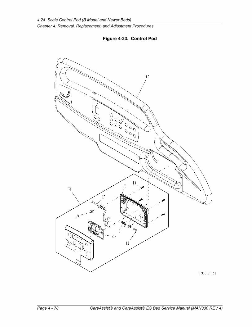
4.24 Scale Control Pod (B Model and Newer Beds) Chapter 4: Removal, Replacement, and Adjustment Procedures
Figure 4-33. Control Pod
Page 4 - 78 CareAssist® and CareAssist® ES Bed Service Manual (MAN330 REV 4)
4.24 Scale Control Pod (B Model and Newer Beds) Chapter 4: Removal, Replacement, and Adjustment Procedures
Replacement 1. Do as follows to the new pod:
a. Remove the four screws (D) from the back of the pod (B).
b. Remove the pod back (E).
c. Disconnect the cable (F) from the P.C. board (G).
2. Put the new pod (B) in position next to the cable (F) that comes out of the siderail (C).
3. Connect the cable (F) to the P.C. board (G).
4. Do the cable routing as noted earlier.
5. Install the pod back (E).
6. Install the four screws (D) to attach the pod back (E) to the pod (B).
7. Install the weldment (H), removed earlier, into the spring (I).
8. Install the pod (B) into the siderail (C).
9. Slide the pod (B) towards the foot end of the siderail (C) so the weldment (H) engages the groove in the siderail.
10. Install the spacer (A).
11. Do the “Function Checks” on page 2-5.
4
CareAssist® and CareAssist® ES Bed Service Manual (MAN330 REV 4) Page 4 - 79
4.25 Scale Control Pod P.C. Board (B Model and Newer Beds) Chapter 4: Removal, Replacement, and Adjustment Procedures
4.25 Scale Control Pod P.C. Board (B Model and Newer Beds) Tools required: T15 Torx®1 screwdriver
(2) Small-bladed screwdriver Antistatic strap
Removal 1. Set the brakes.
2. Raise the siderail to the up and locked position.
WARNING: Unplug the bed from its power source. Failure to do so could cause personal injury or equipment damage.
3. Unplug the bed from its power source. Let the bed sit for 60 seconds for the battery to time out.
4. Remove the spacer (A) (see figure 4-34 on page 4-81).
5. Slide the pod (B) towards the head end of the siderail (C).
6. Pull out the foot end of the pod (B).
7. Slide the pod (B) towards the foot end of the siderail (C), and remove it from the siderail (C).
8. Remove the four screws (D) from the back of the pod (B).
9. Remove the pod back (E).
10. Note the routing of the cable (F).
11. Disconnect the cable (F) from the P.C. board (G).
12. Disconnect the P.C. board (G) from the switch panel cable (H).
1. Torx® is a registered trademark of Acument Intellectual Properties, LLC.
Page 4 - 80 CareAssist® and CareAssist® ES Bed Service Manual (MAN330 REV 4)
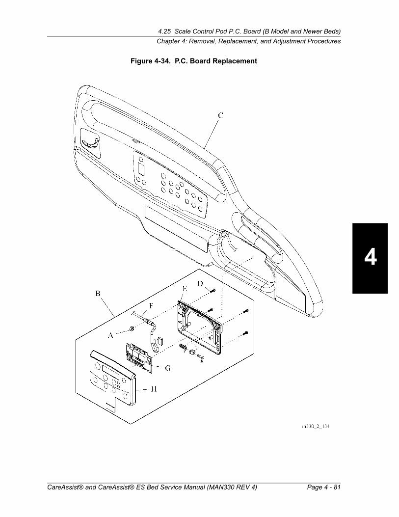
4.25 Scale Control Pod P.C. Board (B Model and Newer Beds) Chapter 4: Removal, Replacement, and Adjustment Procedures
Figure 4-34. P.C. Board Replacement
4
CareAssist® and CareAssist® ES Bed Service Manual (MAN330 REV 4) Page 4 - 81
4.25 Scale Control Pod P.C. Board (B Model and Newer Beds) Chapter 4: Removal, Replacement, and Adjustment Procedures
Replacement 1. Connect the new P.C. board (G) to the switch panel cable (H).
2. Connect the cable (F) to the P.C. board (G).
3. Do the cable routing as noted earlier.
4. Install the pod back (E).
5. Install the four screws (D) to attach the pod back (E) to the pod (B).
6. Install the pod (B) into the siderail (C).
7. Slide the pod (B) toward the foot end of the siderail (C) so the weldment engages the groove in the siderail.
8. Install the spacer (A).
9. Do the “Function Checks” on page 2-5.
Page 4 - 82 CareAssist® and CareAssist® ES Bed Service Manual (MAN330 REV 4)
4.26 Batteries (B Model and Newer Beds) Chapter 4: Removal, Replacement, and Adjustment Procedures
4.26 Batteries (B Model and Newer Beds) Tools required: T25 Torx®1 screwdriver
Removal 1. Set the brakes.
2. Raise the head section to the full up position.
WARNING: Unplug the bed from its power source. Failure to do so could cause personal injury or equipment damage.
3. Unplug the bed from its power source. Let the bed sit for 60 seconds for the battery to time out.
4. Remove the four screws (A) that attach the battery cover (B) to the power supply (C) (see figure 4-35 on page 4-84).
5. Remove the battery cover (B).
6. Note the position of the battery cables (D).
7. Disconnect the cables (D) from the batteries (E).
8. Remove the batteries (E) from the power supply (C).
4
1. Torx® is a registered trademark of Acument Intellectual Properties, LLC.
CareAssist® and CareAssist® ES Bed Service Manual (MAN330 REV 4) Page 4 - 83
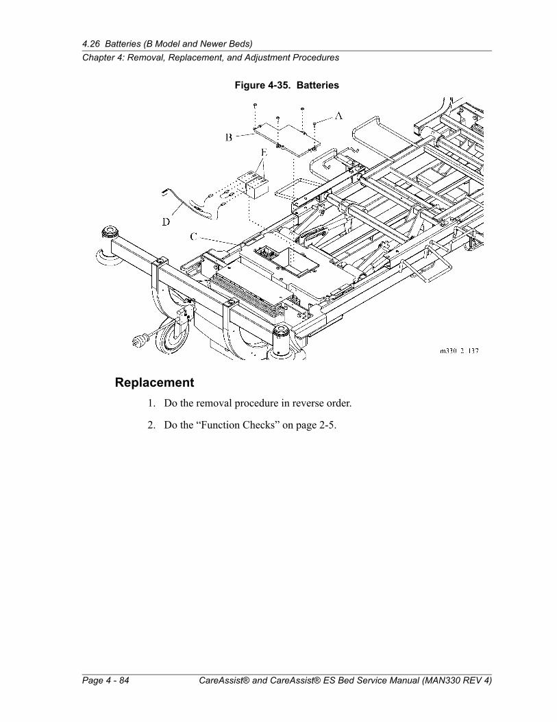
4.26 Batteries (B Model and Newer Beds) Chapter 4: Removal, Replacement, and Adjustment Procedures
Figure 4-35. Batteries
Replacement 1. Do the removal procedure in reverse order.
2. Do the “Function Checks” on page 2-5.
Page 4 - 84 CareAssist® and CareAssist® ES Bed Service Manual (MAN330 REV 4)
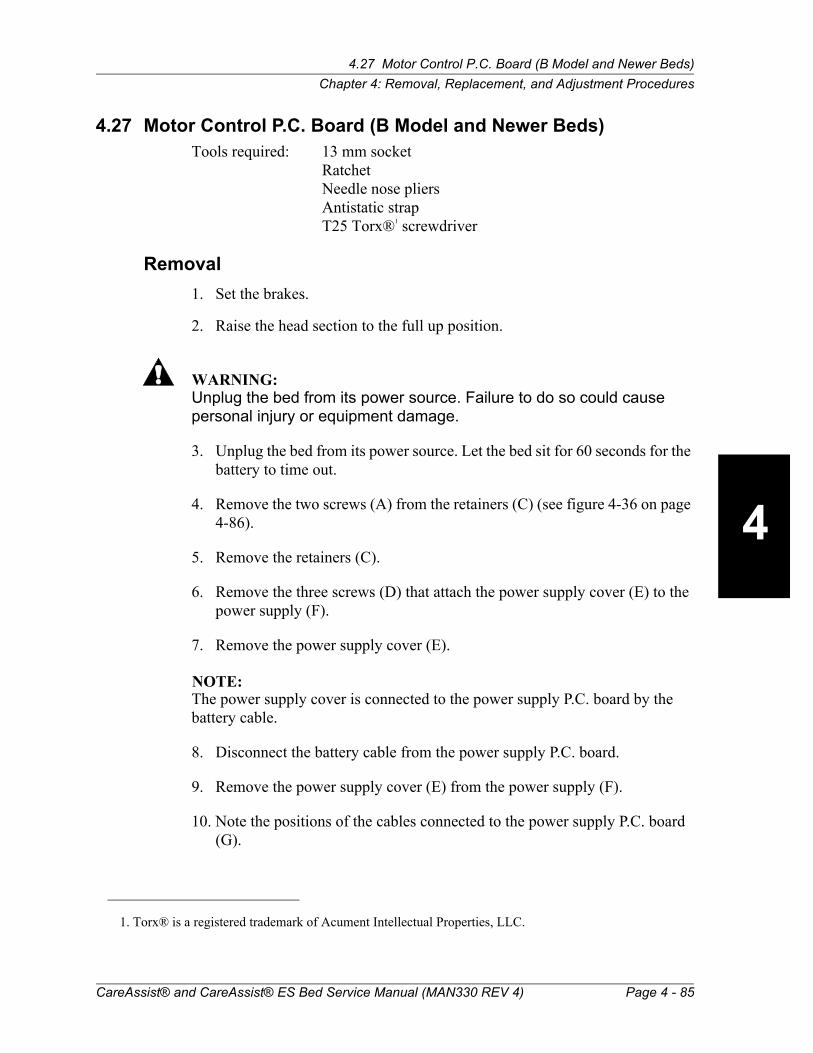
4.27 Motor Control P.C. Board (B Model and Newer Beds) Chapter 4: Removal, Replacement, and Adjustment Procedures
4.27 Motor Control P.C. Board (B Model and Newer Beds) Tools required: 13 mm socket
Ratchet Needle nose pliers Antistatic strap T25 Torx®1 screwdriver
Removal 1. Set the brakes.
2. Raise the head section to the full up position.
WARNING: Unplug the bed from its power source. Failure to do so could cause personal injury or equipment damage.
3. Unplug the bed from its power source. Let the bed sit for 60 seconds for the battery to time out.
4. Remove the two screws (A) from the retainers (C) (see figure 4-36 on page 4-86).
5. Remove the retainers (C).
6. Remove the three screws (D) that attach the power supply cover (E) to the power supply (F).
7. Remove the power supply cover (E).
NOTE: The power supply cover is connected to the power supply P.C. board by the battery cable.
8. Disconnect the battery cable from the power supply P.C. board.
9. Remove the power supply cover (E) from the power supply (F).
10. Note the positions of the cables connected to the power supply P.C. board (G).
1. Torx® is a registered trademark of Acument Intellectual Properties, LLC.
4
CareAssist® and CareAssist® ES Bed Service Manual (MAN330 REV 4) Page 4 - 85
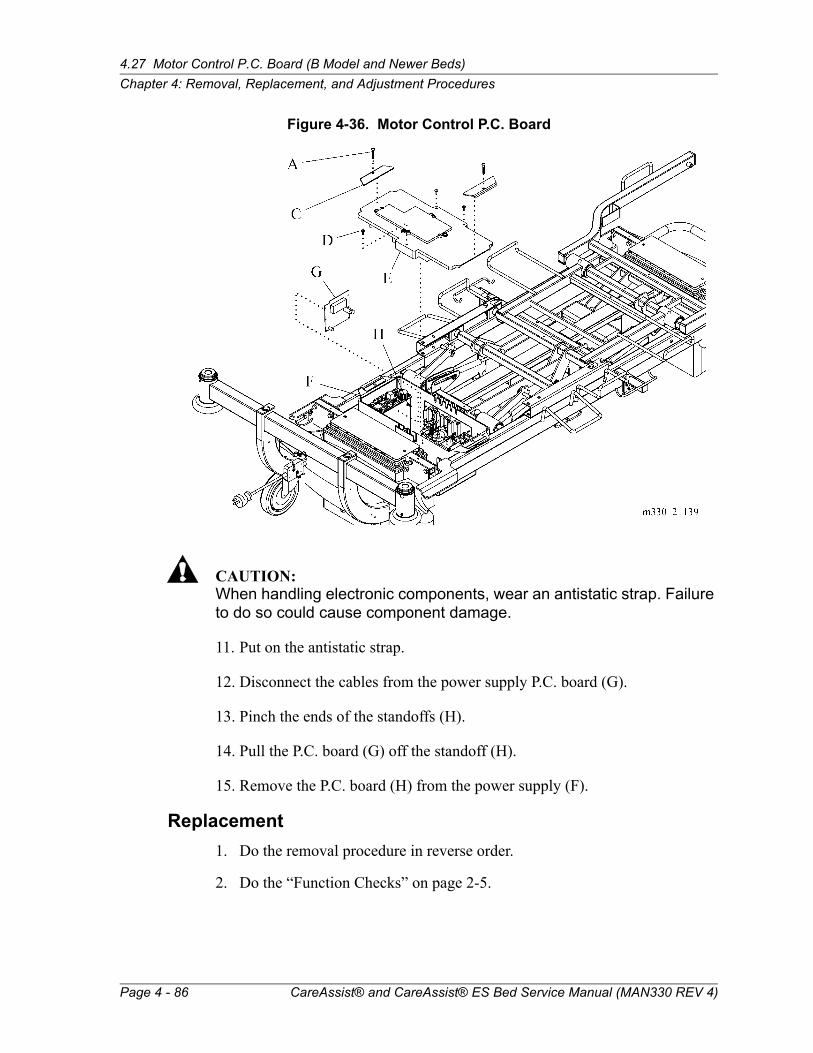
4.27 Motor Control P.C. Board (B Model and Newer Beds) Chapter 4: Removal, Replacement, and Adjustment Procedures
Figure 4-36. Motor Control P.C. Board
CAUTION: When handling electronic components, wear an antistatic strap. Failure to do so could cause component damage.
11. Put on the antistatic strap.
12. Disconnect the cables from the power supply P.C. board (G).
13. Pinch the ends of the standoffs (H).
14. Pull the P.C. board (G) off the standoff (H).
15. Remove the P.C. board (H) from the power supply (F).
Replacement 1. Do the removal procedure in reverse order.
2. Do the “Function Checks” on page 2-5.
Page 4 - 86 CareAssist® and CareAssist® ES Bed Service Manual (MAN330 REV 4)
4.28 SideCom® Communication System P.C. Board (B Model and Newer Beds) Chapter 4: Removal, Replacement, and Adjustment Procedures
4.28 SideCom® Communication System P.C. Board (B Model and Newer Beds)
Tools required: 13 mm socket Ratchet Needle nose pliers Antistatic strap T25 Torx®1 screwdriver
Removal 1. Set the brakes.
2. Raise the head section to the full up position.
WARNING: Unplug the bed from its power source. Failure to do so could cause personal injury or equipment damage.
3. Unplug the bed from its power source. Let the bed sit for 60 seconds for the battery to time out.
4. Remove the two screws (A) from the retainers (C) (see figure 4-37 on page 4-88).
5. Remove the retainers (C).
6. Remove the three screws (D) that attach the power supply cover (E) to the power supply (F).
7. Remove the power supply cover (E).
NOTE: The power supply cover is connected to the power supply P.C. board by the battery cable.
8. Disconnect the battery cable from the power supply P.C. board.
9. Remove the power supply cover (E) from the power supply (F).
4
1. Torx® is a registered trademark of Acument Intellectual Properties, LLC.
CareAssist® and CareAssist® ES Bed Service Manual (MAN330 REV 4) Page 4 - 87
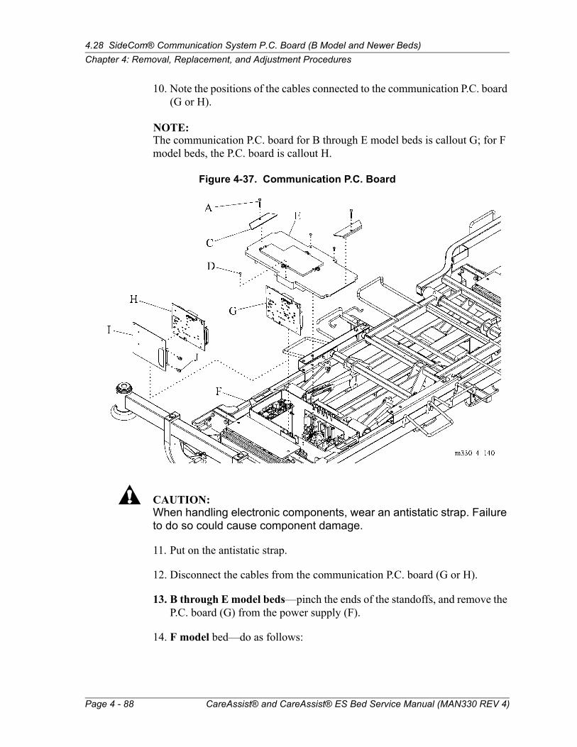
4.28 SideCom® Communication System P.C. Board (B Model and Newer Beds) Chapter 4: Removal, Replacement, and Adjustment Procedures
10. Note the positions of the cables connected to the communication P.C. board (G or H).
NOTE: The communication P.C. board for B through E model beds is callout G; for F model beds, the P.C. board is callout H.
Figure 4-37. Communication P.C. Board
CAUTION: When handling electronic components, wear an antistatic strap. Failure to do so could cause component damage.
11. Put on the antistatic strap.
12. Disconnect the cables from the communication P.C. board (G or H).
13. B through E model beds—pinch the ends of the standoffs, and remove the P.C. board (G) from the power supply (F).
14. F model bed—do as follows:
Page 4 - 88 CareAssist® and CareAssist® ES Bed Service Manual (MAN330 REV 4)
4.28 SideCom® Communication System P.C. Board (B Model and Newer Beds) Chapter 4: Removal, Replacement, and Adjustment Procedures
a. Pinch the ends of the standoffs, and remove the SideCom adapter bracket (I) from the power supply (F).
b. Remove the two screws (J) that attach the P.C. board (H) to the adapter bracket (I).
c. Pinch the ends of the standoffs, and remove the P.C. board (H) from the adapter bracket (I).
Replacement 1. Do the removal procedure in reverse order.
2. Do the “Function Checks” on page 2-5.
4
CareAssist® and CareAssist® ES Bed Service Manual (MAN330 REV 4) Page 4 - 89
4.29 Line Filter (B Model and Newer Beds) Chapter 4: Removal, Replacement, and Adjustment Procedures
4.29 Line Filter (B Model and Newer Beds) Tools required: 13 mm socket
Ratchet Needle nose pliers Antistatic strap T15 Torx®1 screwdriver T25 Torx® screwdriver
Removal 1. Set the brakes.
2. Raise the head section to the full up position.
WARNING: Unplug the bed from its power source. Failure to do so could cause personal injury or equipment damage.
3. Unplug the bed from its power source. Let the bed sit for 60 seconds for the battery to time out.
4. Remove the two screws (A) from the retainers (C) (see figure 4-38 on page 4-91).
5. Remove the retainers (C).
6. Remove the three screws (D) that attach the power supply cover (E) to the power supply (F).
7. Remove the power supply cover (E).
NOTE: The power supply cover is connected to the power supply P.C. board by the battery cable.
8. Disconnect the battery cable from the power supply P.C. board.
9. Remove the power supply cover (E) from the power supply (F).
10. Note the positions of the cables connected to the line filter (G).
1. Torx® is a registered trademark of Acument Intellectual Properties, LLC.
Page 4 - 90 CareAssist® and CareAssist® ES Bed Service Manual (MAN330 REV 4)
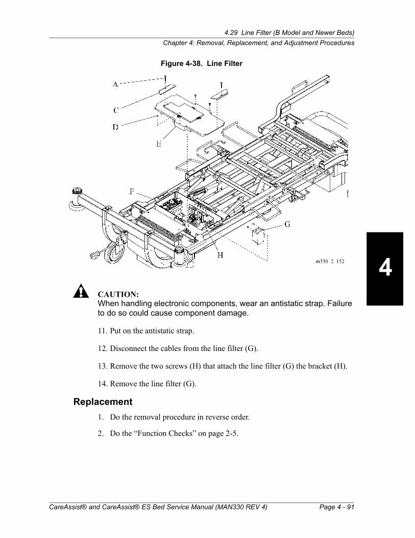
4.29 Line Filter (B Model and Newer Beds) Chapter 4: Removal, Replacement, and Adjustment Procedures
Figure 4-38. Line Filter
CAUTION: When handling electronic components, wear an antistatic strap. Failure to do so could cause component damage.
11. Put on the antistatic strap.
12. Disconnect the cables from the line filter (G).
13. Remove the two screws (H) that attach the line filter (G) the bracket (H).
14. Remove the line filter (G).
Replacement 1. Do the removal procedure in reverse order.
2. Do the “Function Checks” on page 2-5.
4
CareAssist® and CareAssist® ES Bed Service Manual (MAN330 REV 4) Page 4 - 91
4.30 Scale P.C. Board (B Model and Newer Beds) Chapter 4: Removal, Replacement, and Adjustment Procedures
4.30 Scale P.C. Board (B Model and Newer Beds) Tools required: 13 mm socket
Ratchet Needle nose pliers Antistatic strap
Removal 1. Set the brakes.
2. Raise the head section to the full up position.
WARNING: Unplug the bed from its power source. Failure to do so could cause personal injury or equipment damage.
3. Unplug the bed from its power source. Let the bed sit for 60 seconds for the battery to time out.
4. Remove the two screws (A) from the retainers (C) (see figure 4-39 on page 4-93).
5. Remove the retainers (C).
6. Remove the three screws (D) that attach the power supply cover (E) to the power supply (F).
7. Remove the power supply cover (E).
NOTE: The power supply cover is connected to the power supply P.C. board by the battery cable.
8. Disconnect the battery cable from the power supply P.C. board.
9. Remove the power supply cover (E) power supply (F).
10. Note the positions of the cables connected to the scale P.C. board (G).
Page 4 - 92 CareAssist® and CareAssist® ES Bed Service Manual (MAN330 REV 4)
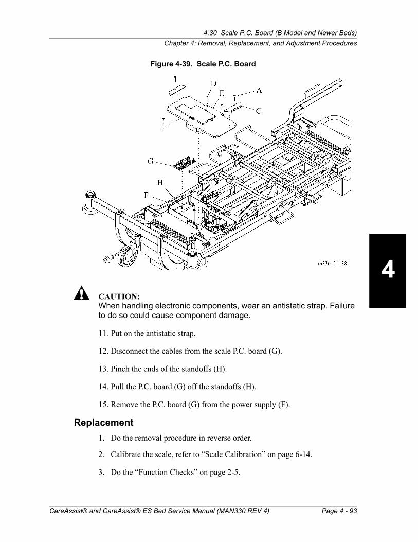
4.30 Scale P.C. Board (B Model and Newer Beds) Chapter 4: Removal, Replacement, and Adjustment Procedures
Figure 4-39. Scale P.C. Board
CAUTION: When handling electronic components, wear an antistatic strap. Failure to do so could cause component damage.
11. Put on the antistatic strap.
12. Disconnect the cables from the scale P.C. board (G).
13. Pinch the ends of the standoffs (H).
14. Pull the P.C. board (G) off the standoffs (H).
15. Remove the P.C. board (G) from the power supply (F).
Replacement 1. Do the removal procedure in reverse order.
2. Calibrate the scale, refer to “Scale Calibration” on page 6-14.
3. Do the “Function Checks” on page 2-5.
4
CareAssist® and CareAssist® ES Bed Service Manual (MAN330 REV 4) Page 4 - 93
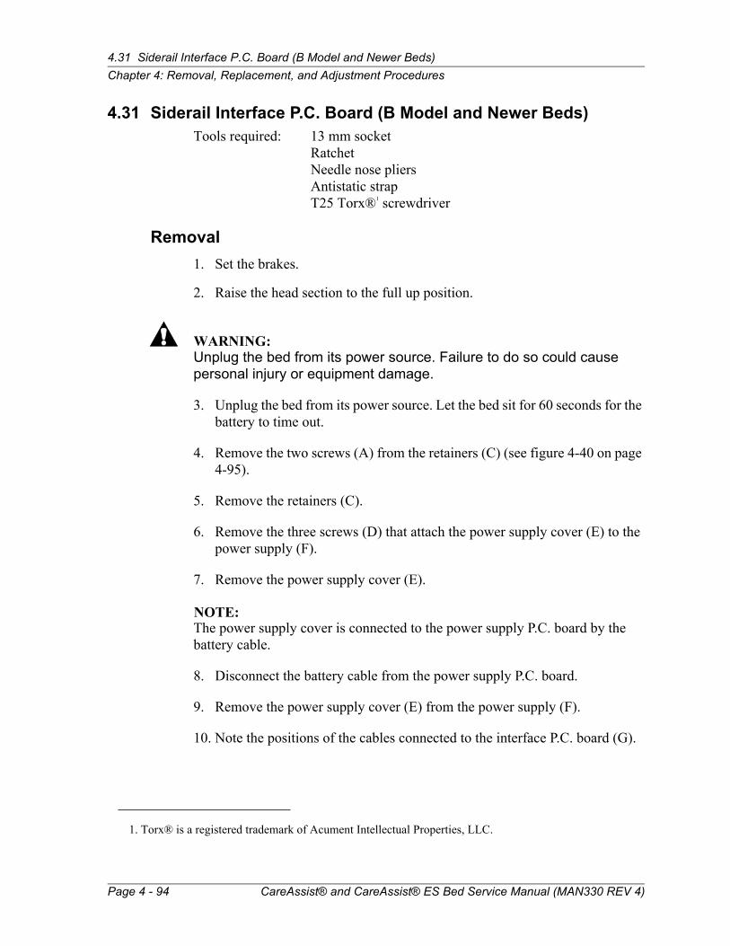
4.31 Siderail Interface P.C. Board (B Model and Newer Beds) Chapter 4: Removal, Replacement, and Adjustment Procedures
4.31 Siderail Interface P.C. Board (B Model and Newer Beds) Tools required: 13 mm socket
Ratchet Needle nose pliers Antistatic strap T25 Torx®1 screwdriver
Removal 1. Set the brakes.
2. Raise the head section to the full up position.
WARNING: Unplug the bed from its power source. Failure to do so could cause personal injury or equipment damage.
3. Unplug the bed from its power source. Let the bed sit for 60 seconds for the battery to time out.
4. Remove the two screws (A) from the retainers (C) (see figure 4-40 on page 4-95).
5. Remove the retainers (C).
6. Remove the three screws (D) that attach the power supply cover (E) to the power supply (F).
7. Remove the power supply cover (E).
NOTE: The power supply cover is connected to the power supply P.C. board by the battery cable.
8. Disconnect the battery cable from the power supply P.C. board.
9. Remove the power supply cover (E) from the power supply (F).
10. Note the positions of the cables connected to the interface P.C. board (G).
1. Torx® is a registered trademark of Acument Intellectual Properties, LLC.
Page 4 - 94 CareAssist® and CareAssist® ES Bed Service Manual (MAN330 REV 4)
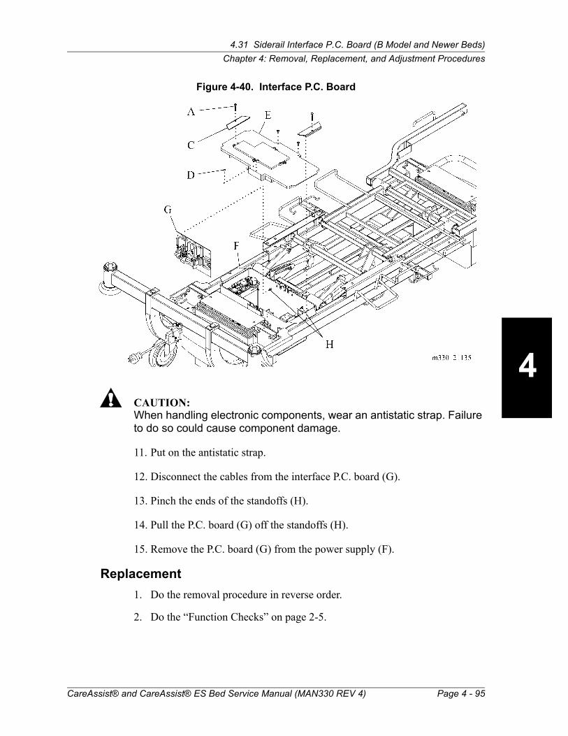
4.31 Siderail Interface P.C. Board (B Model and Newer Beds) Chapter 4: Removal, Replacement, and Adjustment Procedures
Figure 4-40. Interface P.C. Board
CAUTION: When handling electronic components, wear an antistatic strap. Failure to do so could cause component damage.
11. Put on the antistatic strap.
12. Disconnect the cables from the interface P.C. board (G).
13. Pinch the ends of the standoffs (H).
14. Pull the P.C. board (G) off the standoffs (H).
15. Remove the P.C. board (G) from the power supply (F).
Replacement 1. Do the removal procedure in reverse order.
2. Do the “Function Checks” on page 2-5.
4
CareAssist® and CareAssist® ES Bed Service Manual (MAN330 REV 4) Page 4 - 95
4.32 Transformer (B Model and Newer Beds) Chapter 4: Removal, Replacement, and Adjustment Procedures
4.32 Transformer (B Model and Newer Beds) Tools required: 13 mm socket
Ratchet Antistatic strap T25 Torx®1 screwdriver
Removal 1. Set the brakes.
2. Raise the head section to the full up position.
WARNING: Unplug the bed from its power source. Failure to do so could cause personal injury or equipment damage.
3. Unplug the bed from its power source. Let the bed sit for 60 seconds for the battery to time out.
4. Remove the two screws (A) from the retainers (C) (see figure 4-41 on page 4-97).
5. Remove the retainers (C).
6. Remove the three screws (D) that attach the power supply cover (E) to the power supply (F).
7. Remove the power supply cover (E).
NOTE: The power supply cover is connected to the power supply P.C. board by the battery cable.
8. Disconnect the battery cable from the power supply P.C. board.
9. Remove the power supply cover (E).
10. Note the positions of the cables connected to the transformer (G).
1. Torx® is a registered trademark of Acument Intellectual Properties, LLC.
Page 4 - 96 CareAssist® and CareAssist® ES Bed Service Manual (MAN330 REV 4)
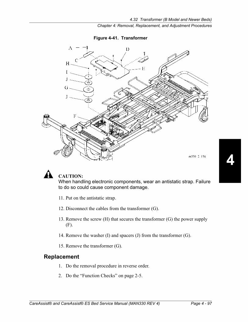
4.32 Transformer (B Model and Newer Beds) Chapter 4: Removal, Replacement, and Adjustment Procedures
Figure 4-41. Transformer
CAUTION: When handling electronic components, wear an antistatic strap. Failure to do so could cause component damage.
11. Put on the antistatic strap.
12. Disconnect the cables from the transformer (G).
13. Remove the screw (H) that secures the transformer (G) the power supply (F).
14. Remove the washer (I) and spacers (J) from the transformer (G).
15. Remove the transformer (G).
Replacement 1. Do the removal procedure in reverse order.
2. Do the “Function Checks” on page 2-5.
4
CareAssist® and CareAssist® ES Bed Service Manual (MAN330 REV 4) Page 4 - 97
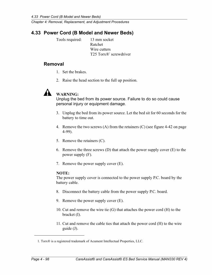
4.33 Power Cord (B Model and Newer Beds) Chapter 4: Removal, Replacement, and Adjustment Procedures
4.33 Power Cord (B Model and Newer Beds) Tools required: 13 mm socket
Ratchet Wire cutters T25 Torx®1 screwdriver
Removal 1. Set the brakes.
2. Raise the head section to the full up position.
WARNING: Unplug the bed from its power source. Failure to do so could cause personal injury or equipment damage.
3. Unplug the bed from its power source. Let the bed sit for 60 seconds for the battery to time out.
4. Remove the two screws (A) from the retainers (C) (see figure 4-42 on page 4-99).
5. Remove the retainers (C).
6. Remove the three screws (D) that attach the power supply cover (E) to the power supply (F).
7. Remove the power supply cover (E).
NOTE: The power supply cover is connected to the power supply P.C. board by the battery cable.
8. Disconnect the battery cable from the power supply P.C. board.
9. Remove the power supply cover (E).
10. Cut and remove the wire tie (G) that attaches the power cord (H) to the bracket (I).
11. Cut and remove the cable ties that attach the power cord (H) to the wire guide (J).
1. Torx® is a registered trademark of Acument Intellectual Properties, LLC.
Page 4 - 98 CareAssist® and CareAssist® ES Bed Service Manual (MAN330 REV 4)
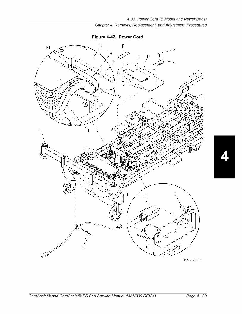
4.33 Power Cord (B Model and Newer Beds) Chapter 4: Removal, Replacement, and Adjustment Procedures
Figure 4-42. Power Cord
4
CareAssist® and CareAssist® ES Bed Service Manual (MAN330 REV 4) Page 4 - 99

4.33 Power Cord (B Model and Newer Beds) Chapter 4: Removal, Replacement, and Adjustment Procedures
12. Remove the two screws (K) that attach the power cord (H) to the bed (L).
13. Remove the power cord (H) from the bed (L).
Replacement 1. Put the mark (M) on the power cord (H) so the edge of the mark (M) is
even with the edge of the wire guide (J).
2. Put the other mark (M) on the power cord (H) so the edge of the mark (M) is even with the enclosure entrance on the power supply (F).
3. Do the removal procedure in reverse order.
4. Do the “Function Checks” on page 2-5.
Page 4 - 100 CareAssist® and CareAssist® ES Bed Service Manual (MAN330 REV 4)
4.34 Fuses (B Model and Newer Beds) Chapter 4: Removal, Replacement, and Adjustment Procedures
4.34 Fuses (B Model and Newer Beds) Tools required: 13 mm socket
Ratchet Antistatic strap T25 Torx®1 screwdriver
Removal 1. Set the brakes.
2. Raise the head section to the full up position.
WARNING: Unplug the bed from its power source. Failure to do so could cause personal injury or equipment damage.
3. Unplug the bed from its power source. Let the bed sit for 60 seconds for the battery to time out.
4. For the mains fuses, do as follows, otherwise go to step 5.
a. Remove the two screws (A) from the retainers (C) (see figure 4-43 on page 4-102).
b. Remove the retainers (C).
c. Remove the three screws (D) that attach the power supply cover (E) to the power supply (F).
d. Remove the power supply cover (E).
NOTE: The power supply cover is connected to the power supply P.C. board by the battery cable.
e. Disconnect the battery cable from the power supply P.C. board.
f. Remove the power supply cover (E).
4
CAUTION: When handling electronic components, wear an antistatic strap. Failure to do so could cause component damage.
g. Put on the antistatic strap.
1. Torx® is a registered trademark of Acument Intellectual Properties, LLC.
CareAssist® and CareAssist® ES Bed Service Manual (MAN330 REV 4) Page 4 - 101
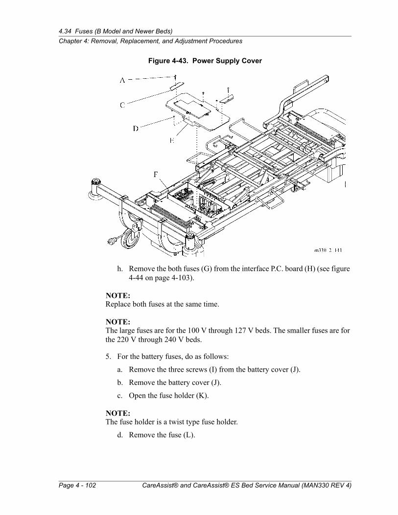
4.34 Fuses (B Model and Newer Beds) Chapter 4: Removal, Replacement, and Adjustment Procedures
Figure 4-43. Power Supply Cover
h. Remove the both fuses (G) from the interface P.C. board (H) (see figure 4-44 on page 4-103).
NOTE: Replace both fuses at the same time.
NOTE: The large fuses are for the 100 V through 127 V beds. The smaller fuses are for the 220 V through 240 V beds.
5. For the battery fuses, do as follows:
a. Remove the three screws (I) from the battery cover (J).
b. Remove the battery cover (J).
c. Open the fuse holder (K).
NOTE: The fuse holder is a twist type fuse holder.
d. Remove the fuse (L).
Page 4 - 102 CareAssist® and CareAssist® ES Bed Service Manual (MAN330 REV 4)
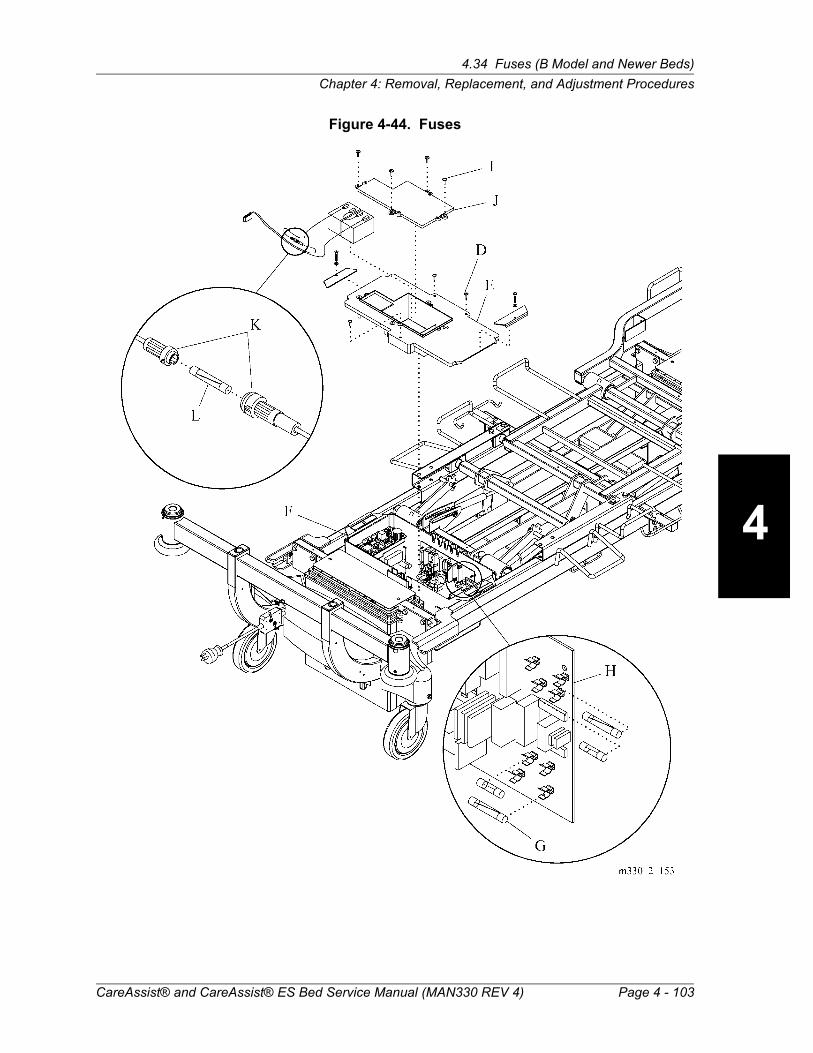
4.34 Fuses (B Model and Newer Beds) Chapter 4: Removal, Replacement, and Adjustment Procedures
Figure 4-44. Fuses
4
CareAssist® and CareAssist® ES Bed Service Manual (MAN330 REV 4) Page 4 - 103
4.34 Fuses (B Model and Newer Beds) Chapter 4: Removal, Replacement, and Adjustment Procedures
Replacement 1. Do the removal procedure in reverse order.
2. Do the “Function Checks” on page 2-5.
Page 4 - 104 CareAssist® and CareAssist® ES Bed Service Manual (MAN330 REV 4)
4.35 Fifth Wheel Chapter 4: Removal, Replacement, and Adjustment Procedures
4.35 Fifth Wheel Tools required: 13 mm wrench
Ratchet Extension Scissor jack
Removal 1. Set the brakes.
2. Raise the bed to its highest position.
SHOCK HAZARD: Unplug the bed from its power source. Failure to do so could cause personal injury or equipment damage.
3. Unplug the bed from its power source. Let the bed sit for 60 seconds for the battery to time out.
4. Use the scissor jack to raise the bed high enough to remove the fifth wheel.
5. Remove the screws (A), washers (B) and locknuts (C) from the fifth wheel (D).(see figure 4-45 on page 4-106) 4
WARNING: Use correct lifting techniques. Failure to do so can cause personal injury or equipment damage.
6. Remove the fifth wheel (D).
CareAssist® and CareAssist® ES Bed Service Manual (MAN330 REV 4) Page 4 - 105
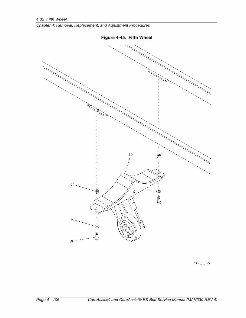
4.35 Fifth Wheel Chapter 4: Removal, Replacement, and Adjustment Procedures
Figure 4-45. Fifth Wheel
Page 4 - 106 CareAssist® and CareAssist® ES Bed Service Manual (MAN330 REV 4)
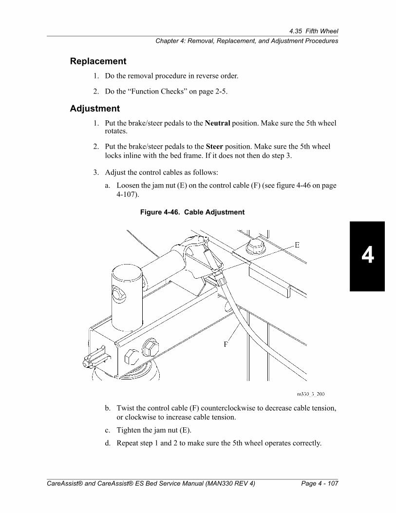
4.35 Fifth Wheel Chapter 4: Removal, Replacement, and Adjustment Procedures
Replacement 1. Do the removal procedure in reverse order.
2. Do the “Function Checks” on page 2-5.
Adjustment 1. Put the brake/steer pedals to the Neutral position. Make sure the 5th wheel
rotates.
2. Put the brake/steer pedals to the Steer position. Make sure the 5th wheel locks inline with the bed frame. If it does not then do step 3.
3. Adjust the control cables as follows:
a. Loosen the jam nut (E) on the control cable (F) (see figure 4-46 on page 4-107).
Figure 4-46. Cable Adjustment
4
b. Twist the control cable (F) counterclockwise to decrease cable tension, or clockwise to increase cable tension.
c. Tighten the jam nut (E).
d. Repeat step 1 and 2 to make sure the 5th wheel operates correctly.
CareAssist® and CareAssist® ES Bed Service Manual (MAN330 REV 4) Page 4 - 107
4.36 Head-End Brake/Steer Pedal Chapter 4: Removal, Replacement, and Adjustment Procedures
4.36 Head-End Brake/Steer Pedal Tools required: 13 mm wrench
Removal 1. Set the foot end brakes.
2. Raise the bed to its highest position.
SHOCK HAZARD: Unplug the bed from its power source. Failure to do so could cause personal injury or equipment damage.
3. Unplug the bed from its power source. Let the bed sit for 60 seconds for the battery to time out.
4. Remove the screws (A) and washers (B) from the brake pedal (C). (see figure 4-47 on page 4-109).
5. Remove the brake pedal (C) and spacers (D) from the brake rod (E).
Page 4 - 108 CareAssist® and CareAssist® ES Bed Service Manual (MAN330 REV 4)
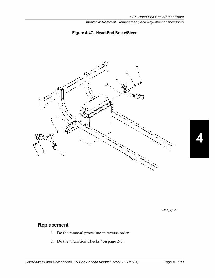
4.36 Head-End Brake/Steer Pedal Chapter 4: Removal, Replacement, and Adjustment Procedures
Figure 4-47. Head-End Brake/Steer
4
Replacement 1. Do the removal procedure in reverse order.
2. Do the “Function Checks” on page 2-5.
CareAssist® and CareAssist® ES Bed Service Manual (MAN330 REV 4) Page 4 - 109
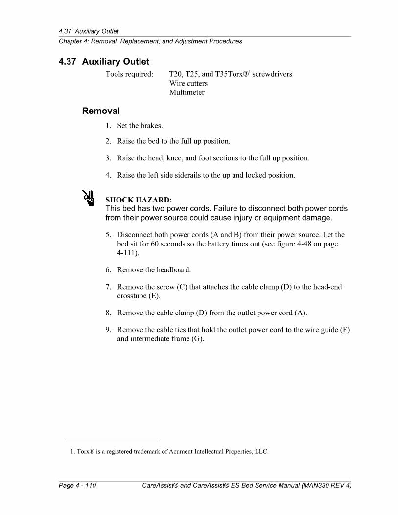
4.37 Auxiliary Outlet Chapter 4: Removal, Replacement, and Adjustment Procedures
4.37 Auxiliary Outlet Tools required: T20, T25, and T35Torx®1 screwdrivers
Wire cutters Multimeter
Removal 1. Set the brakes.
2. Raise the bed to the full up position.
3. Raise the head, knee, and foot sections to the full up position.
4. Raise the left side siderails to the up and locked position.
SHOCK HAZARD: This bed has two power cords. Failure to disconnect both power cords from their power source could cause injury or equipment damage.
5. Disconnect both power cords (A and B) from their power source. Let the bed sit for 60 seconds so the battery times out (see figure 4-48 on page 4-111).
6. Remove the headboard.
7. Remove the screw (C) that attaches the cable clamp (D) to the head-end crosstube (E).
8. Remove the cable clamp (D) from the outlet power cord (A).
9. Remove the cable ties that hold the outlet power cord to the wire guide (F) and intermediate frame (G).
1. Torx® is a registered trademark of Acument Intellectual Properties, LLC.
Page 4 - 110 CareAssist® and CareAssist® ES Bed Service Manual (MAN330 REV 4)
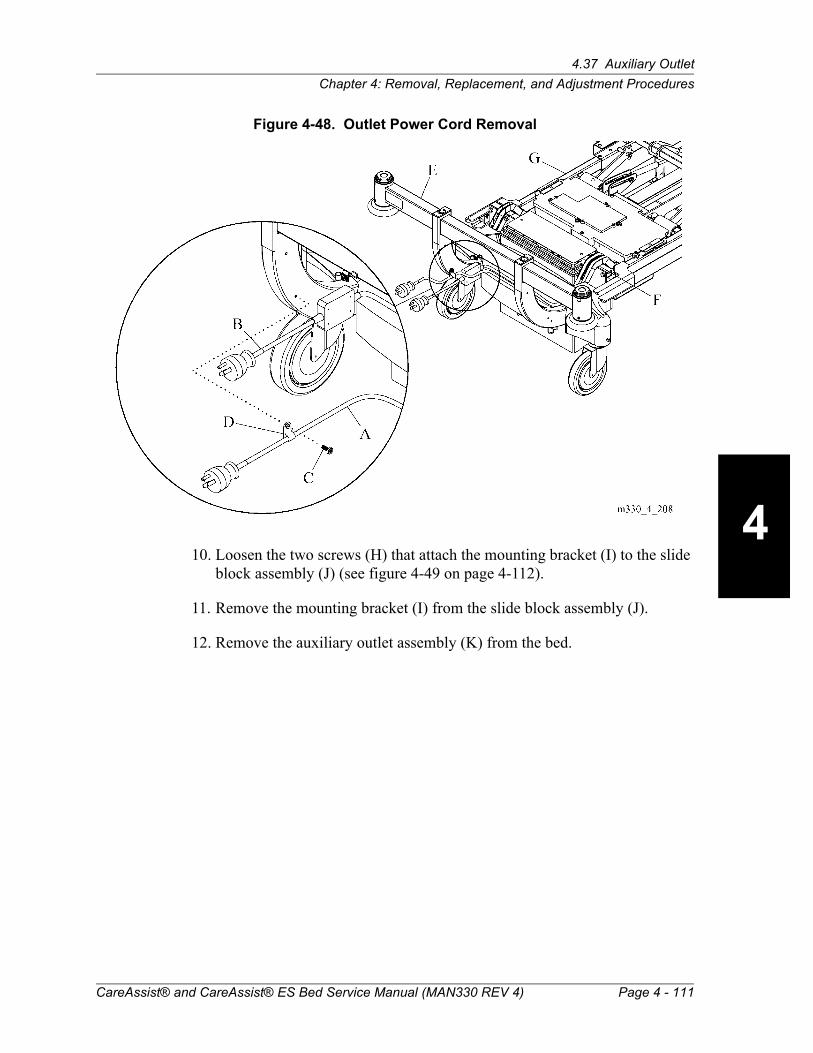
4.37 Auxiliary Outlet Chapter 4: Removal, Replacement, and Adjustment Procedures
Figure 4-48. Outlet Power Cord Removal
10. Loosen the two screws (H) that attach the mounting bracket (I) to the slide block assembly (J) (see figure 4-49 on page 4-112).
11. Remove the mounting bracket (I) from the slide block assembly (J).
12. Remove the auxiliary outlet assembly (K) from the bed.
4
CareAssist® and CareAssist® ES Bed Service Manual (MAN330 REV 4) Page 4 - 111
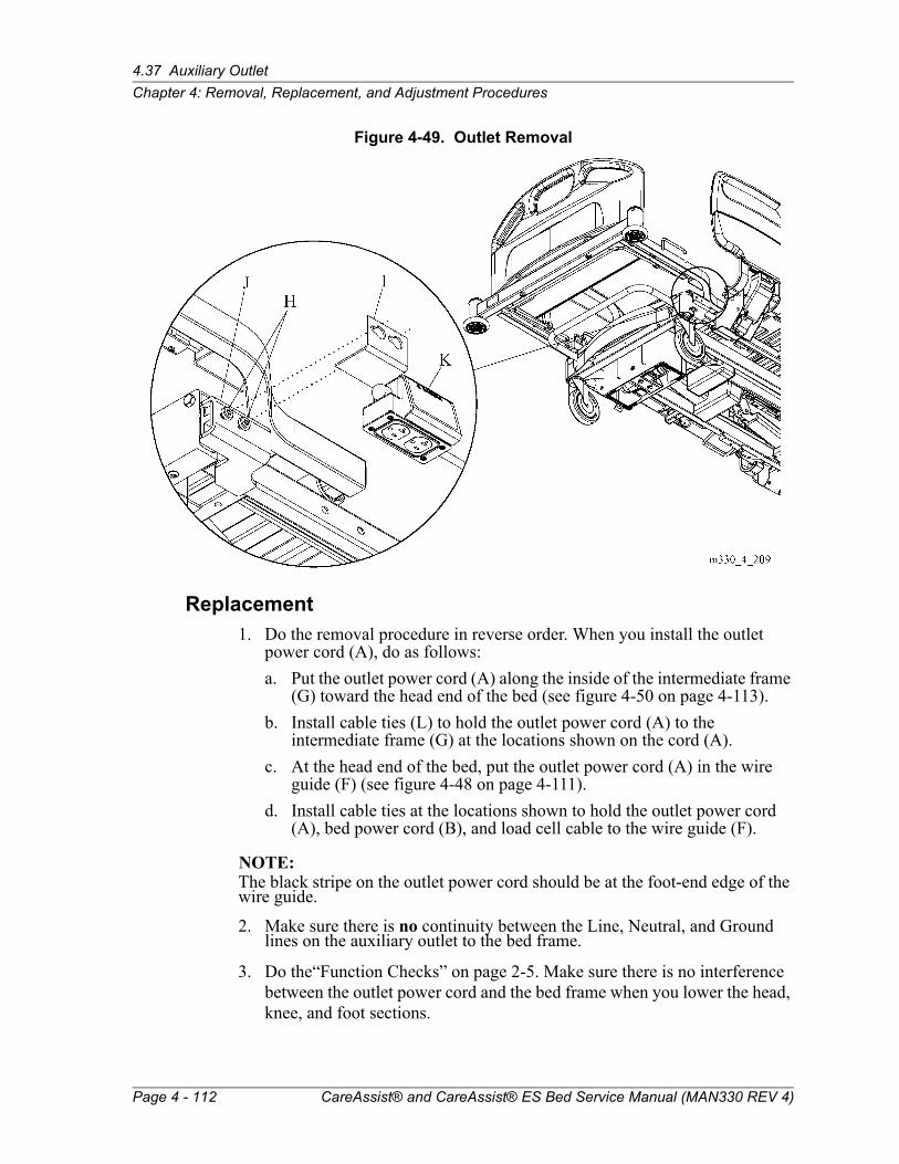
4.37 Auxiliary Outlet Chapter 4: Removal, Replacement, and Adjustment Procedures
Figure 4-49. Outlet Removal
Replacement 1. Do the removal procedure in reverse order. When you install the outlet
power cord (A), do as follows: a. Put the outlet power cord (A) along the inside of the intermediate frame
(G) toward the head end of the bed (see figure 4-50 on page 4-113). b. Install cable ties (L) to hold the outlet power cord (A) to the
intermediate frame (G) at the locations shown on the cord (A). c. At the head end of the bed, put the outlet power cord (A) in the wire
guide (F) (see figure 4-48 on page 4-111). d. Install cable ties at the locations shown to hold the outlet power cord
(A), bed power cord (B), and load cell cable to the wire guide (F).
NOTE: The black stripe on the outlet power cord should be at the foot-end edge of the wire guide.
2. Make sure there is no continuity between the Line, Neutral, and Ground lines on the auxiliary outlet to the bed frame.
3. Do the“Function Checks” on page 2-5. Make sure there is no interference between the outlet power cord and the bed frame when you lower the head, knee, and foot sections.
Page 4 - 112 CareAssist® and CareAssist® ES Bed Service Manual (MAN330 REV 4)
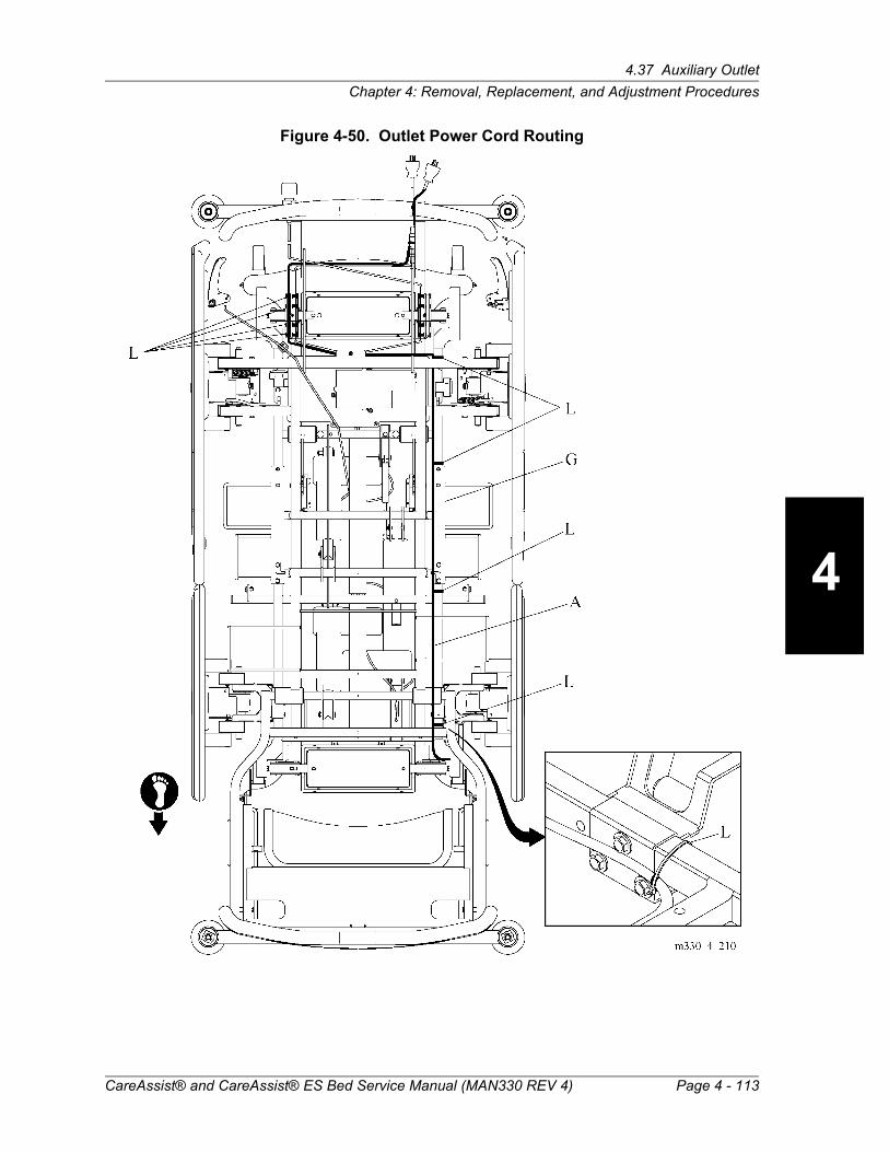
4.37 Auxiliary Outlet Chapter 4: Removal, Replacement, and Adjustment Procedures
Figure 4-50. Outlet Power Cord Routing
4
CareAssist® and CareAssist® ES Bed Service Manual (MAN330 REV 4) Page 4 - 113
4.38 SafeView™ Alerts Chapter 4: Removal, Replacement, and Adjustment Procedures
4.38 SafeView™ Alerts Tools required: T25 Torx®1 screwdriver Wire cutters
Needle nose pliers Antistatic strap Weight, 50 lb (23 kg) minimum
Removal and Replacement 1. Set the brakes.
2. Fully extend the foot section.
3. Raise the bed to the high position.
4. Raise the head section to the highest position.
SHOCK HAZARD: Failure to unplug the bed from its power source could cause injury or equipment damage.
5. Unplug the bed from its power source. Let the bed sit for 60 seconds so the battery will time out.
6. Remove the two screws (A) from the retainers (C) (see figure 4-51 on page 4-115).
7. Remove the retainers (C).
8. Remove the three screws (D) that attach the power supply cover (E) to the power supply (F).
9. Remove the power supply cover (E).
1. Torx® is a registered trademark of Acument Intellectual Properties, LLC.
Page 4 - 114 CareAssist® and CareAssist® ES Bed Service Manual (MAN330 REV 4)
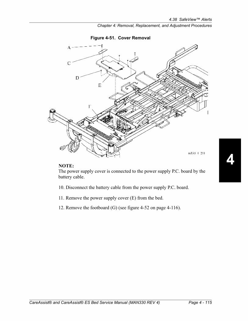
4.38 SafeView™ Alerts Chapter 4: Removal, Replacement, and Adjustment Procedures
Figure 4-51. Cover Removal
NOTE: The power supply cover is connected to the power supply P.C. board by the battery cable.
10. Disconnect the battery cable from the power supply P.C. board.
11. Remove the power supply cover (E) from the bed.
12. Remove the footboard (G) (see figure 4-52 on page 4-116).
4
CareAssist® and CareAssist® ES Bed Service Manual (MAN330 REV 4) Page 4 - 115
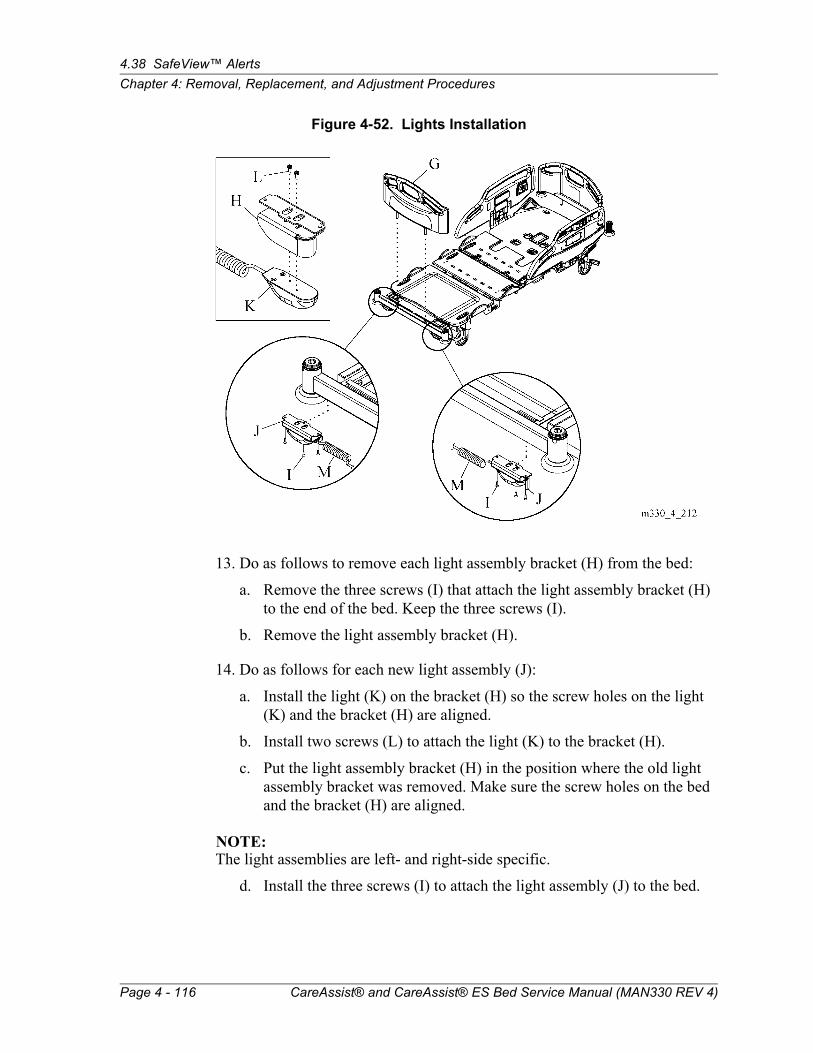
4.38 SafeView™ Alerts Chapter 4: Removal, Replacement, and Adjustment Procedures
Figure 4-52. Lights Installation
13. Do as follows to remove each light assembly bracket (H) from the bed:
a. Remove the three screws (I) that attach the light assembly bracket (H) to the end of the bed. Keep the three screws (I).
b. Remove the light assembly bracket (H).
14. Do as follows for each new light assembly (J):
a. Install the light (K) on the bracket (H) so the screw holes on the light (K) and the bracket (H) are aligned.
b. Install two screws (L) to attach the light (K) to the bracket (H).
c. Put the light assembly bracket (H) in the position where the old light assembly bracket was removed. Make sure the screw holes on the bed and the bracket (H) are aligned.
NOTE: The light assemblies are left- and right-side specific.
d. Install the three screws (I) to attach the light assembly (J) to the bed.
Page 4 - 116 CareAssist® and CareAssist® ES Bed Service Manual (MAN330 REV 4)
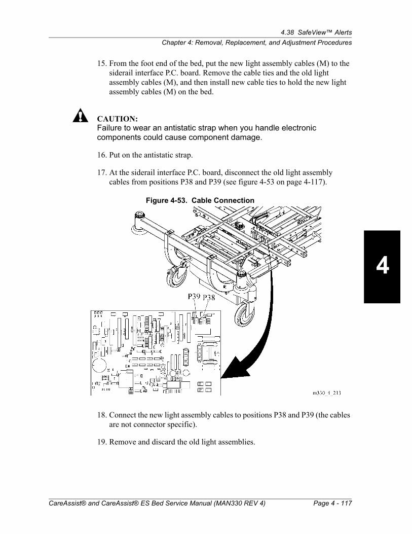
4.38 SafeView™ Alerts Chapter 4: Removal, Replacement, and Adjustment Procedures
15. From the foot end of the bed, put the new light assembly cables (M) to the siderail interface P.C. board. Remove the cable ties and the old light assembly cables (M), and then install new cable ties to hold the new light assembly cables (M) on the bed.
CAUTION: Failure to wear an antistatic strap when you handle electronic components could cause component damage.
16. Put on the antistatic strap.
17. At the siderail interface P.C. board, disconnect the old light assembly cables from positions P38 and P39 (see figure 4-53 on page 4-117).
Figure 4-53. Cable Connection
18. Connect the new light assembly cables to positions P38 and P39 (the cables are not connector specific).
19. Remove and discard the old light assemblies.
4
CareAssist® and CareAssist® ES Bed Service Manual (MAN330 REV 4) Page 4 - 117
4.38 SafeView™ Alerts Chapter 4: Removal, Replacement, and Adjustment Procedures
20. Connect the bed to AC power. If the lights flash yellow and green, there is a technical problem with the lights. Make sure all part installations and cable connections are correct.
21. Put the bed is in the safe condition as follows:
• Put the bed in the low position.
• Put the applicable siderails up as configured (see “Configure the Side-rails for the Safe Bed Condition” on page 4-119).
• Set the brake.
22. Put a minimum of 50 lb (23 kg) of weight on the bed.
23. Activate The Bed Exit Alarm System, and then do these checks to make sure the lights operate correctly:
a. With the bed in the safe condition; the lights are on green.
b. Raise, and then lower the bed. The lights flash yellow when the bed is raised, and the lights are on green when the bed is in the low position.
c. Lower, and then raise each siderail (two head end, and as applicable, one or both foot end). The lights flash yellow when one of the siderails is lowered, and the lights are on green when all applicable siderails are up.
d. Release, and then set the brake. The lights flash yellow when the brake is released, and the lights are on green when the brake is set.
e. Deactivate the Bed Exit Alarm System. The lights are off.
24. Remove the 50 lb (23 kg) of weight from the bed.
25. Do the “Function Checks” on page 2-5.
Page 4 - 118 CareAssist® and CareAssist® ES Bed Service Manual (MAN330 REV 4)
4.38 SafeView™ Alerts Chapter 4: Removal, Replacement, and Adjustment Procedures
Configure the Siderails for the Safe Bed Condition
At a minimum, the two head-end siderails must be up for the lights to show green. To configure the system so that one or both of the foot siderails must also be up for the lights to show green, do as follows:
1. Put the two head-end and one or both of the foot-end siderails in the up position.
2. Press these controls at the same time for five seconds: Knee Up, Knee Down, Bed Up, and Bed Down. The lights will flash green for three seconds to let you know the configuration was set.
3. To change the configuration so that only the two head-end siderails must be up, do step 2 with only the two head-end siderails up.
4
CareAssist® and CareAssist® ES Bed Service Manual (MAN330 REV 4) Page 4 - 119
4.38 SafeView™ Alerts Chapter 4: Removal, Replacement, and Adjustment Procedures
NOTES:
Page 4 - 120 CareAssist® and CareAssist® ES Bed Service Manual (MAN330 REV 4)
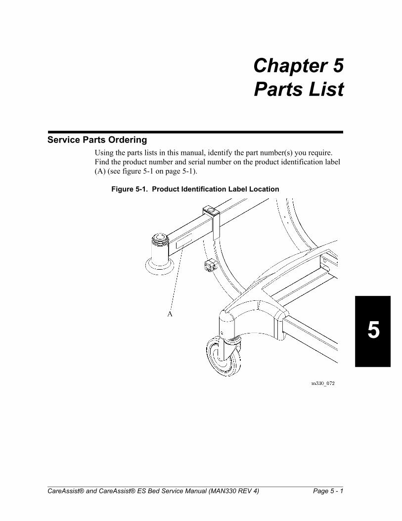
Chapter 5 Parts List
Service Parts Ordering Using the parts lists in this manual, identify the part number(s) you require. Find the product number and serial number on the product identification label (A) (see figure 5-1 on page 5-1).
Figure 5-1. Product Identification Label Location
5
CareAssist® and CareAssist® ES Bed Service Manual (MAN330 REV 4) Page 5 - 1
Service Parts Ordering Chapter 5: Parts List
Call Hill-Rom Technical Support at (800) 445-3720 with the following information:
• Customer account number
• Purchase order number
• Product number
• Serial number
• Part number(s)
To promptly order parts, request part prices and availability, or follow up on a service order, use the following Hill-Rom fax number:
(812) 934-8472
Terms:
• Net 30 days
• F.O.B. Batesville, IN
• Prepaid shipping charges added to invoice
• All orders shipped ground transportation unless specified
Address all inquiries to:
ATTN TECHNICAL SUPPORT—PARTS HILL-ROM COMPANY, INC. 1069 STATE ROUTE 46 E BATESVILLE IN 47006-9167
Address all return goods to:
ATTN SERVICE STORES DISTRIBUTION CENTER DOOR D23 HILL-ROM COMPANY, INC. COUNTY ROAD 300E BATESVILLE IN 47006-9167
NOTE: To eliminate possible delays or incorrect billings, do not return any items without a Return Material Authorization (RMA) number. When a return is requested, an RMA packet is included with each order. This packet includes an RMA number, instructions, and a shipping label. If an RMA number is not available, obtain one by phoning Hill-Rom Technical Support at (800) 445-3720.
Page 5 - 2 CareAssist® and CareAssist® ES Bed Service Manual (MAN330 REV 4)
Exchange Policy Chapter 5: Parts List
Exchange Policy The following are policies for in-warranty and out-of-warranty exchanges from Hill-Rom.
In-Warranty Exchanges
In some cases, Hill-Rom will request that parts/products be returned for inspection. When this occurs, you are expected to return parts/products within 30 days of receipt of the exchange part. If you fail to return the inoperative parts/products within the 30 day period, Hill-Rom will invoice your facility for the full selling price of the parts/products.
NOTE: The preceding billing procedure pertains only to parts/products that Hill-Rom requests to be returned.
In some cases, the invoice accompanying the parts will show the full selling price (only for internal use at Hill-Rom). Do not confuse this price with your price.
Do not return any parts without an RMA number. When parts/products have been requested to be returned, Hill-Rom will include an RMA packet with the parts/products shipment. If an RMA number is not available, obtain one by phoning Hill-Rom Technical Support at (800) 445-3720.
Out-of-Warranty Exchanges
You are expected to return the inoperative parts/products within 30 days of receipt of the exchange part. Hill-Rom will include an RMA packet with the parts/products shipment. If an RMA number is not available, obtain one by phoning Hill-Rom Technical Support at (800) 445-3720. Hill-Rom will invoice your facility for the full selling price of the parts/products. Upon return of the inoperative parts/products, Hill-Rom will issue a credit to your facility for the difference between the exchange price and the full selling price of the parts/products.
5
CareAssist® and CareAssist® ES Bed Service Manual (MAN330 REV 4) Page 5 - 3
Warranty Chapter 5: Parts List
Warranty HILL-ROM COMPANY, INC.
LIMITED WARRANTY Hill-Rom Company, Inc. (Hill-Rom) has a long tradition of providing superior products and service to our customers. Our goal is “Total Customer Satisfaction”. In that spirit, Hill-Rom is proud to offer the following warranty. GENERAL WARRANTY (APPLICABLE UNLESS A SPECIFIC WARRANTY IS LISTED) Hill-Rom warrants to the original purchaser that its products and replacement parts shall be free from defects in material and workmanship for a period of one (1) year from date of delivery. Hill-Rom’s obligation under this warranty is expressly limited to supplying replacement parts and/or service for, or replacing, at its option, any product which is, in the sole discretion of Hill-Rom, found to be defective. In addition to the foregoing one year warranty, Hill-Rom warrants to the original purchaser that the frame and welds on its products will be free from structural defects for the life of the product. Any product upgrade or modification initiated by Hill-Rom does not affect the original product warranty. SPECIFIC WARRANTIES MATTRESS WARRANTIES Hill-Rom warrants to the original purchaser that its mattress product shall be free from defects in material and workmanship for a period of two (2) years from date of delivery. However, electro mechanical mattress components (compressors, valves, printed circuit boards, hoses, and couplers) are covered by the general one (1) year warranty. EXPENDABLES WARRANTIES A sixty (60) day limited warranty from date of delivery applies to expendable parts such as cushions, coverlets, software diskettes, locator badge batteries, dome light incandescent bulbs, overhead fluorescent tubes, heating elements, temperature probes, filter sheets, and microspheres. This warranty is limited to replacement of the parts covered. TO OBTAIN PARTS AND SERVICE In the United States, call Hill-Rom Technical Support Department at (800) 445-3720, Monday through Friday. In Canada, call Hill-Rom Technical Support Department at (800) 267-2337, Monday through Friday. Outside the United States and Canada, call your authorized Hill-Rom Distributor. In order to expedite service, we request you furnish the following information: customer identification number, product model number, serial number, and description of problem. A qualified specialist will provide, via telephone (United States and Canada), or FAX (Outside the United States and Canada), troubleshooting assistance for facility personnel and provide necessary parts to make repairs. If troubleshooting determines the need for on-site technical service, a qualified service representative will be dispatched. Replacement of non-technical items will be the responsibility of the customer. If requested by Hill-Rom, products or parts for which a warranty claim is made shall be returned prepaid to Hill-Rom’s factory. OUT OF WARRANTY EXCHANGE POLICY After the expiration of the original warranty, upon request, Hill-Rom will ship as a replacement, components such as selected: motors and printed circuit boards, for like units returned to Hill-Rom by the original purchaser at a substantial savings. Please call Hill-Rom Technical Support Department for current pricing. PARTS AVAILABILITY POLICY Hill-Rom will offer parts for new and remanufactured products for ten (10) years from date of sale; for communications products for five (5) years from date of sale. Note: Some original component parts and assemblies may not be available; functional equivalents may be substituted. THE FOREGOING WARRANTIES ARE EXCLUSIVE AND IN LIEU OF ALL OTHER EXPRESS WARRANTIES AND IMPLIED WARRANTIES, INCLUDING BUT NOT LIMITED TO, THE IMPLIED WARRANTIES OF MERCHANTABILITY AND FITNESS OF PURPOSE. HILL-ROM’S OBLIGATION UNDER THESE WARRANTIES SHALL NOT INCLUDE ANY LIABILITY FOR LOSS OF PROFITS, DIRECT, INDIRECT OR CONSEQUENTIAL DAMAGES OR DELAYS. Some states, provinces, or countries do not allow the exclusion or limitation of incidental or consequential damages, so the above exclusion or limitation may not apply. Any improper or negligent use, any alterations or repairs not in accordance with Hill-Rom’s manuals or performed by others in such manner as in Hill-Rom’s sole judgment affects the product materially and adversely, shall void these warranties. These warranties do not cover failures due to misuse, abuse, neglect, or lack of routine maintenance. No employee or representative of Hill-Rom is authorized to change these warranties in any way or grant any other warranty unless in writing and signed by a Hill-Rom officer. These warranties provide specific legal rights; but, there may be other available rights, which vary from state to state, province to province, or country to country. Revised July 6, 2001
Hill-Rom Company, Inc., 1069 State Route 46 E, Batesville, IN 47006-9167
Page 5 - 4 CareAssist® and CareAssist® ES Bed Service Manual (MAN330 REV 4)

Warranty Chapter 5: Parts List
NOTES:
5
CareAssist® and CareAssist® ES Bed Service Manual (MAN330 REV 4) Page 5 - 5
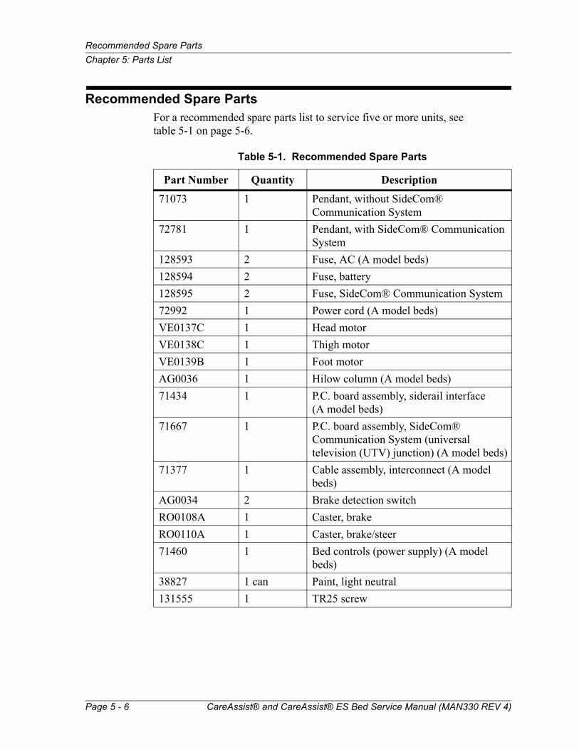
Recommended Spare Parts Chapter 5: Parts List
Recommended Spare Parts For a recommended spare parts list to service five or more units, see table 5-1 on page 5-6.
Table 5-1. Recommended Spare Parts
Part Number Quantity Description
71073 1 Pendant, without SideCom® Communication System
72781 1 Pendant, with SideCom® Communication System
128593 2 Fuse, AC (A model beds) 128594 2 Fuse, battery 128595 2 Fuse, SideCom® Communication System 72992 1 Power cord (A model beds) VE0137C 1 Head motor VE0138C 1 Thigh motor VE0139B 1 Foot motor AG0036 1 Hilow column (A model beds) 71434 1 P.C. board assembly, siderail interface
(A model beds) 71667 1 P.C. board assembly, SideCom®
Communication System (universal television (UTV) junction) (A model beds)
71377 1 Cable assembly, interconnect (A model beds)
AG0034 2 Brake detection switch RO0108A 1 Caster, brake RO0110A 1 Caster, brake/steer 71460 1 Bed controls (power supply) (A model
beds) 38827 1 can Paint, light neutral 131555 1 TR25 screw
Page 5 - 6 CareAssist® and CareAssist® ES Bed Service Manual (MAN330 REV 4)
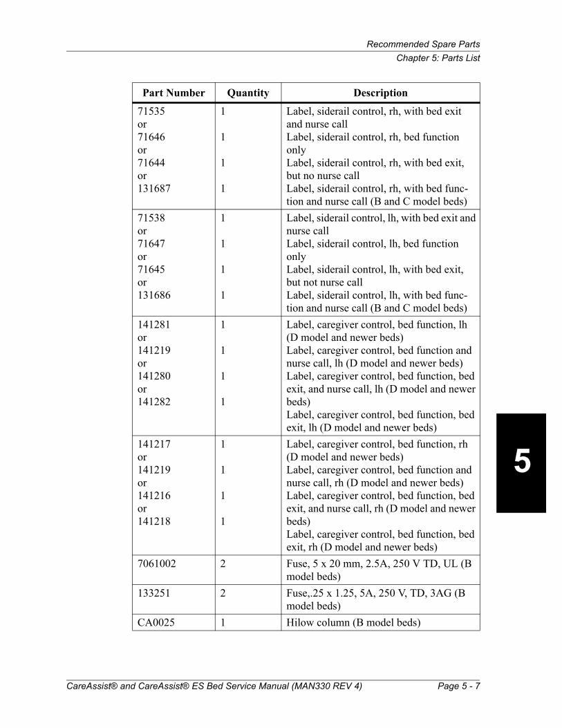
Recommended Spare Parts Chapter 5: Parts List
Part Number Quantity Description
71535 1 Label, siderail control, rh, with bed exit or and nurse call 71646 1 Label, siderail control, rh, bed function or only 71644 1 Label, siderail control, rh, with bed exit, or but no nurse call 131687 1 Label, siderail control, rh, with bed func
tion and nurse call (B and C model beds) 71538 1 Label, siderail control, lh, with bed exit and or nurse call 71647 1 Label, siderail control, lh, bed function or only 71645 1 Label, siderail control, lh, with bed exit, or but not nurse call 131686 1 Label, siderail control, lh, with bed func
tion and nurse call (B and C model beds) 141281 1 Label, caregiver control, bed function, lh or (D model and newer beds) 141219 1 Label, caregiver control, bed function and or nurse call, lh (D model and newer beds) 141280 1 Label, caregiver control, bed function, bed or exit, and nurse call, lh (D model and newer 141282 1 beds)
Label, caregiver control, bed function, bed exit, lh (D model and newer beds)
141217 1 Label, caregiver control, bed function, rh or (D model and newer beds) 141219 1 Label, caregiver control, bed function and or nurse call, rh (D model and newer beds) 141216 1 Label, caregiver control, bed function, bed or exit, and nurse call, rh (D model and newer 141218 1 beds)
Label, caregiver control, bed function, bed exit, rh (D model and newer beds)
7061002 2 Fuse, 5 x 20 mm, 2.5A, 250 V TD, UL (B model beds)
133251 2 Fuse,.25 x 1.25, 5A, 250 V, TD, 3AG (B model beds)
CA0025 1 Hilow column (B model beds)
5
CareAssist® and CareAssist® ES Bed Service Manual (MAN330 REV 4) Page 5 - 7
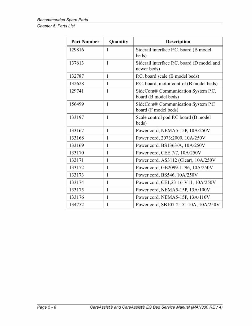
Recommended Spare Parts Chapter 5: Parts List
Part Number Quantity Description
129816 1 Siderail interface P.C. board (B model beds)
137613 1 Siderail interface P.C. board (D model and newer beds)
132787 1 P.C. board scale (B model beds) 132628 1 P.C. board, motor control (B model beds) 129741 1 SideCom® Communication System P.C.
board (B model beds) 156499 1 SideCom® Communication System P.C
board (F model beds) 133197 1 Scale control pod P.C board (B model
beds) 133167 1 Power cord, NEMA5-15P, 10A/250V 133168 1 Power cord, 2073:2000, 10A/250V 133169 1 Power cord, BS1363/A, 10A/250V 133170 1 Power cord, CEE 7/7, 10A/250V 133171 1 Power cord, AS3112 (Clear), 10A/250V 133172 1 Power cord, GB2099.1-’96, 10A/250V 133173 1 Power cord, BS546, 10A/250V 133174 1 Power cord, CE1,23-16-V11, 10A/250V 133175 1 Power cord, NEMA5-15P, 13A/100V 133176 1 Power cord, NEMA5-15P, 13A/110V 134752 1 Power cord, SB107-2-D1-10A, 10A/250V
Page 5 - 8 CareAssist® and CareAssist® ES Bed Service Manual (MAN330 REV 4)
Recommended Spare Parts Chapter 5: Parts List
NOTES:
5
CareAssist® and CareAssist® ES Bed Service Manual (MAN330 REV 4) Page 5 - 9
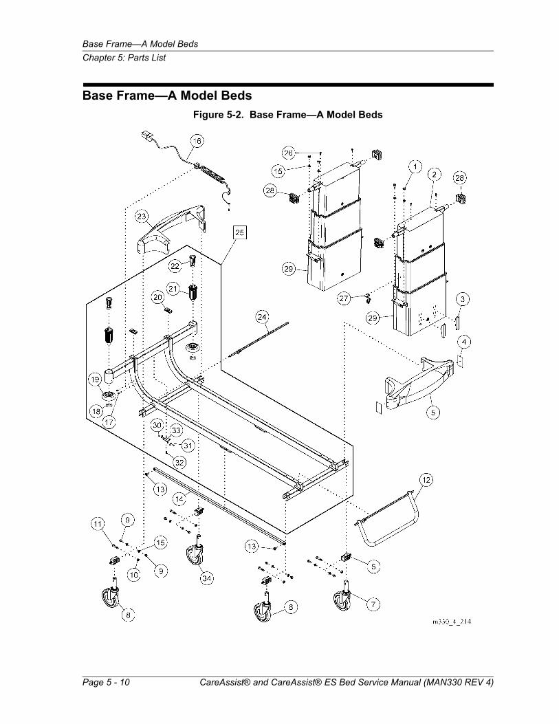
Base Frame—A Model Beds Chapter 5: Parts List
Base Frame—A Model Beds Figure 5-2. Base Frame—A Model Beds
Page 5 - 10 CareAssist® and CareAssist® ES Bed Service Manual (MAN330 REV 4)
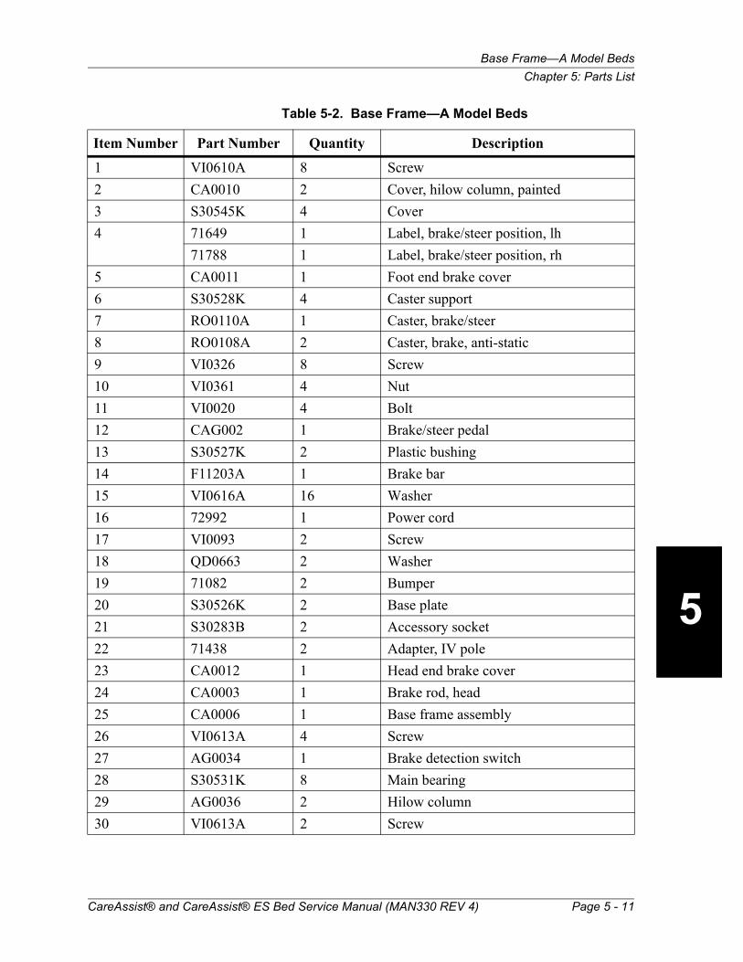
Base Frame—A Model Beds Chapter 5: Parts List
Table 5-2. Base Frame—A Model Beds
Item Number Part Number Quantity Description
1 VI0610A 8 Screw 2 CA0010 2 Cover, hilow column, painted 3 S30545K 4 Cover 4 71649 1 Label, brake/steer position, lh
71788 1 Label, brake/steer position, rh 5 CA0011 1 Foot end brake cover 6 S30528K 4 Caster support 7 RO0110A 1 Caster, brake/steer 8 RO0108A 2 Caster, brake, anti-static 9 VI0326 8 Screw 10 VI0361 4 Nut 11 VI0020 4 Bolt 12 CAG002 1 Brake/steer pedal 13 S30527K 2 Plastic bushing 14 F11203A 1 Brake bar 15 VI0616A 16 Washer 16 72992 1 Power cord 17 VI0093 2 Screw 18 QD0663 2 Washer 19 71082 2 Bumper 20 S30526K 2 Base plate 21 S30283B 2 Accessory socket 22 71438 2 Adapter, IV pole 23 CA0012 1 Head end brake cover 24 CA0003 1 Brake rod, head 25 CA0006 1 Base frame assembly 26 VI0613A 4 Screw 27 AG0034 1 Brake detection switch 28 S30531K 8 Main bearing 29 AG0036 2 Hilow column 30 VI0613A 2 Screw
5
CareAssist® and CareAssist® ES Bed Service Manual (MAN330 REV 4) Page 5 - 11
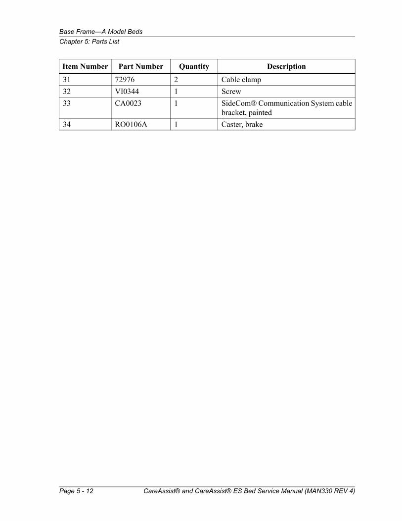
Base Frame—A Model Beds Chapter 5: Parts List
Item Number Part Number Quantity Description
31 72976 2 Cable clamp 32 VI0344 1 Screw 33 CA0023 1 SideCom® Communication System cable
bracket, painted 34 RO0106A 1 Caster, brake
Page 5 - 12 CareAssist® and CareAssist® ES Bed Service Manual (MAN330 REV 4)
Base Frame—A Model Beds Chapter 5: Parts List
NOTES:
5
CareAssist® and CareAssist® ES Bed Service Manual (MAN330 REV 4) Page 5 - 13
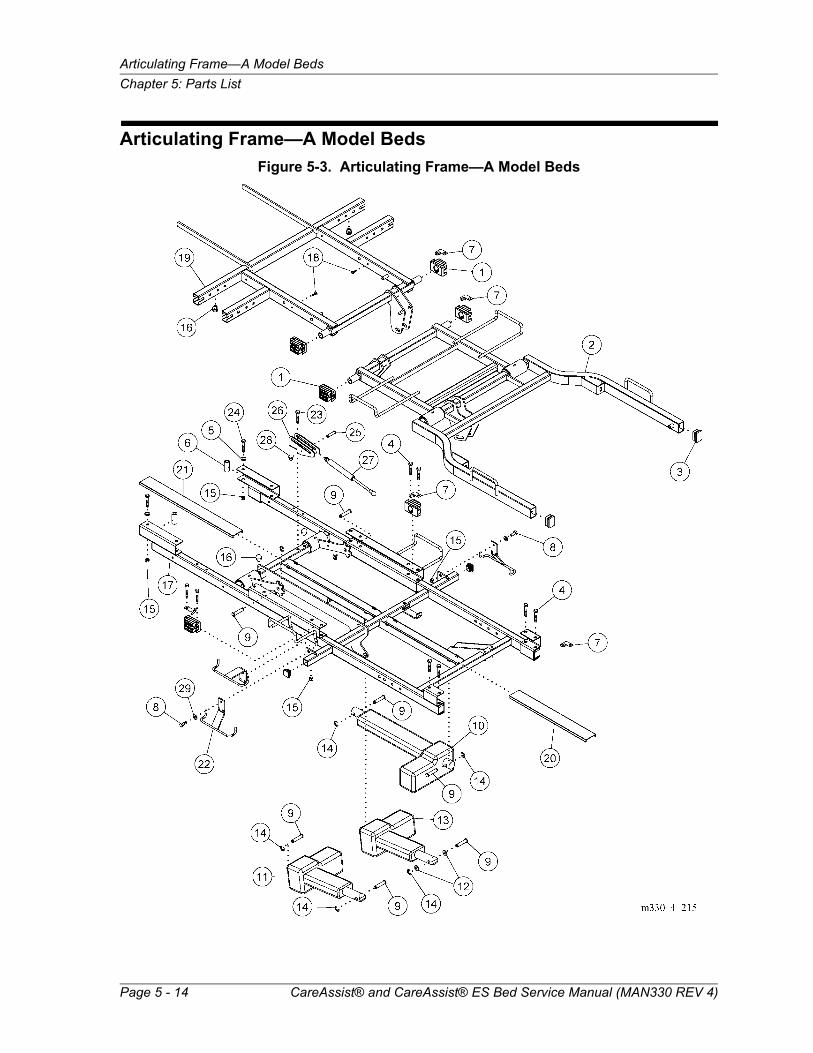
Articulating Frame—A Model Beds Chapter 5: Parts List
Articulating Frame—A Model Beds Figure 5-3. Articulating Frame—A Model Beds
Page 5 - 14 CareAssist® and CareAssist® ES Bed Service Manual (MAN330 REV 4)
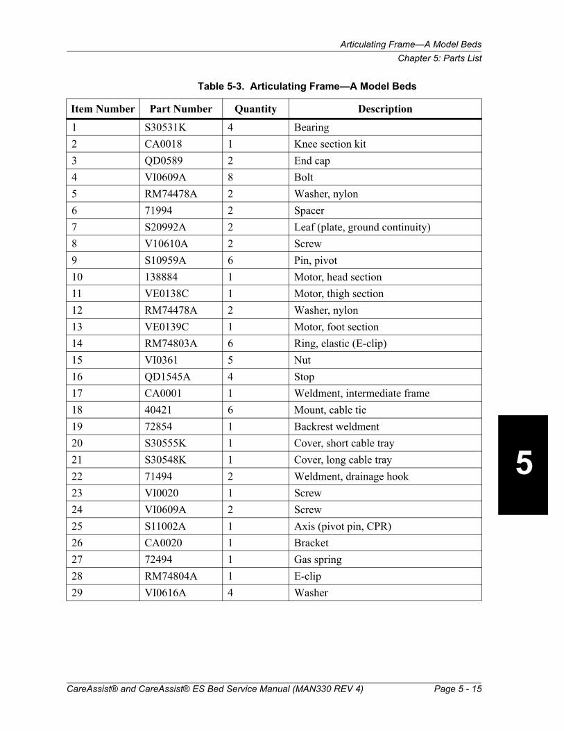
Articulating Frame—A Model Beds Chapter 5: Parts List
Table 5-3. Articulating Frame—A Model Beds
Item Number Part Number Quantity Description
1 S30531K 4 Bearing 2 CA0018 1 Knee section kit 3 QD0589 2 End cap 4 VI0609A 8 Bolt 5 RM74478A 2 Washer, nylon 6 71994 2 Spacer 7 S20992A 2 Leaf (plate, ground continuity) 8 V10610A 2 Screw 9 S10959A 6 Pin, pivot 10 138884 1 Motor, head section 11 VE0138C 1 Motor, thigh section 12 RM74478A 2 Washer, nylon 13 VE0139C 1 Motor, foot section 14 RM74803A 6 Ring, elastic (E-clip) 15 VI0361 5 Nut 16 QD1545A 4 Stop 17 CA0001 1 Weldment, intermediate frame 18 40421 6 Mount, cable tie 19 72854 1 Backrest weldment 20 S30555K 1 Cover, short cable tray 21 S30548K 1 Cover, long cable tray 22 71494 2 Weldment, drainage hook 23 VI0020 1 Screw 24 VI0609A 2 Screw 25 S11002A 1 Axis (pivot pin, CPR) 26 CA0020 1 Bracket 27 72494 1 Gas spring 28 RM74804A 1 E-clip 29 VI0616A 4 Washer
5
CareAssist® and CareAssist® ES Bed Service Manual (MAN330 REV 4) Page 5 - 15
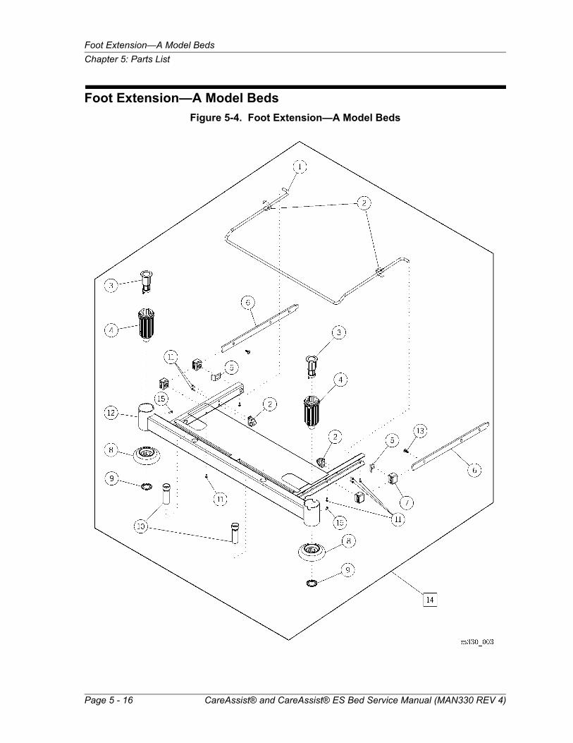
Foot Extension—A Model Beds Chapter 5: Parts List
Foot Extension—A Model Beds Figure 5-4. Foot Extension—A Model Beds
Page 5 - 16 CareAssist® and CareAssist® ES Bed Service Manual (MAN330 REV 4)

Foot Extension—A Model Beds Chapter 5: Parts List
Table 5-4. Foot Extension—A Model Beds
Item Number Part Number Quantity Description
1 71266 1 Handle, foot extension release 2 S30314 2 Stage poignee extension 3 71438 2 Spacer, IV pole adapter 4 S30283B 2 Accessory socket 5 S20998B 2 Blade 6 71265 2 Bar, foot extension 7 S30315A 4 Guide, foot extend 8 71082 2 Bumper 9 QD0663 2 Push nut 10 S30534L 2 Foot board socket 11 VI0554A 8 Screw 12 CA0013 1 Extension, foot weldment 13 VI0608A 2 Screw 14 CA0005 1 Extension, foot assembly 15 VI0613A 2 Screw
5
CareAssist® and CareAssist® ES Bed Service Manual (MAN330 REV 4) Page 5 - 17
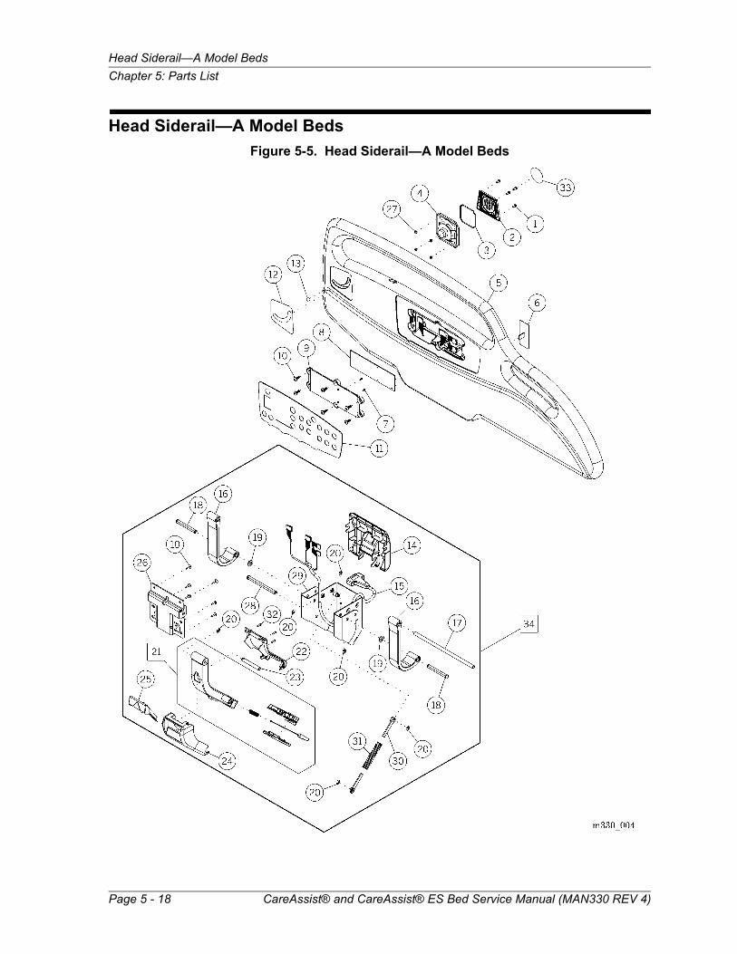
Head Siderail—A Model Beds Chapter 5: Parts List
Head Siderail—A Model Beds Figure 5-5. Head Siderail—A Model Beds
Page 5 - 18 CareAssist® and CareAssist® ES Bed Service Manual (MAN330 REV 4)
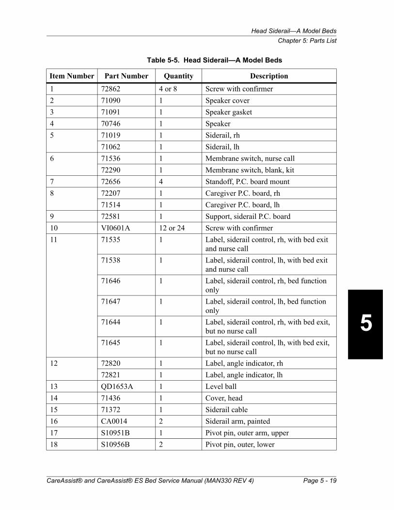
Head Siderail—A Model Beds Chapter 5: Parts List
Table 5-5. Head Siderail—A Model Beds
Item Number Part Number Quantity Description
1 72862 4 or 8 Screw with confirmer 2 71090 1 Speaker cover 3 71091 1 Speaker gasket 4 70746 1 Speaker 5 71019 1 Siderail, rh
71062 1 Siderail, lh 6 71536 1 Membrane switch, nurse call
72290 1 Membrane switch, blank, kit 7 72656 4 Standoff, P.C. board mount 8 72207 1 Caregiver P.C. board, rh
71514 1 Caregiver P.C. board, lh 9 72581 1 Support, siderail P.C. board 10 VI0601A 12 or 24 Screw with confirmer 11 71535 1 Label, siderail control, rh, with bed exit
and nurse call 71538 1 Label, siderail control, lh, with bed exit
and nurse call 71646 1 Label, siderail control, rh, bed function
only 71647 1 Label, siderail control, lh, bed function
only 71644 1 Label, siderail control, rh, with bed exit,
but no nurse call 71645 1 Label, siderail control, lh, with bed exit,
but no nurse call 12 72820 1 Label, angle indicator, rh
72821 1 Label, angle indicator, lh 13 QD1653A 1 Level ball 14 71436 1 Cover, head 15 71372 1 Siderail cable 16 CA0014 2 Siderail arm, painted 17 S10951B 1 Pivot pin, outer arm, upper 18 S10956B 2 Pivot pin, outer, lower
5
CareAssist® and CareAssist® ES Bed Service Manual (MAN330 REV 4) Page 5 - 19
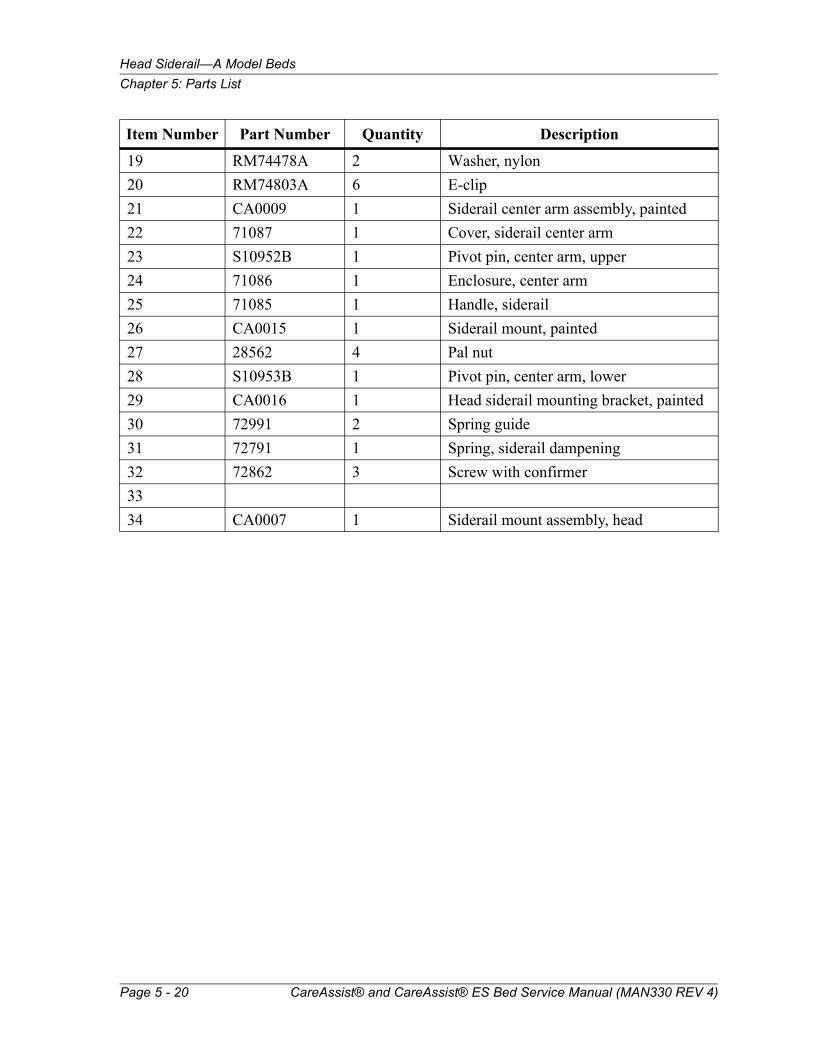
Head Siderail—A Model Beds Chapter 5: Parts List
Item Number Part Number Quantity Description
19 RM74478A 2 Washer, nylon 20 RM74803A 6 E-clip 21 CA0009 1 Siderail center arm assembly, painted 22 71087 1 Cover, siderail center arm 23 S10952B 1 Pivot pin, center arm, upper 24 71086 1 Enclosure, center arm 25 71085 1 Handle, siderail 26 CA0015 1 Siderail mount, painted 27 28562 4 Pal nut 28 S10953B 1 Pivot pin, center arm, lower 29 CA0016 1 Head siderail mounting bracket, painted 30 72991 2 Spring guide 31 72791 1 Spring, siderail dampening 32 72862 3 Screw with confirmer 33 34 CA0007 1 Siderail mount assembly, head
Page 5 - 20 CareAssist® and CareAssist® ES Bed Service Manual (MAN330 REV 4)

Head Siderail—A Model Beds Chapter 5: Parts List
NOTES:
5
CareAssist® and CareAssist® ES Bed Service Manual (MAN330 REV 4) Page 5 - 21

Foot Siderail—A Model Beds Chapter 5: Parts List
Foot Siderail—A Model Beds Figure 5-6. Foot Siderail—A Model Beds
Page 5 - 22 CareAssist® and CareAssist® ES Bed Service Manual (MAN330 REV 4)
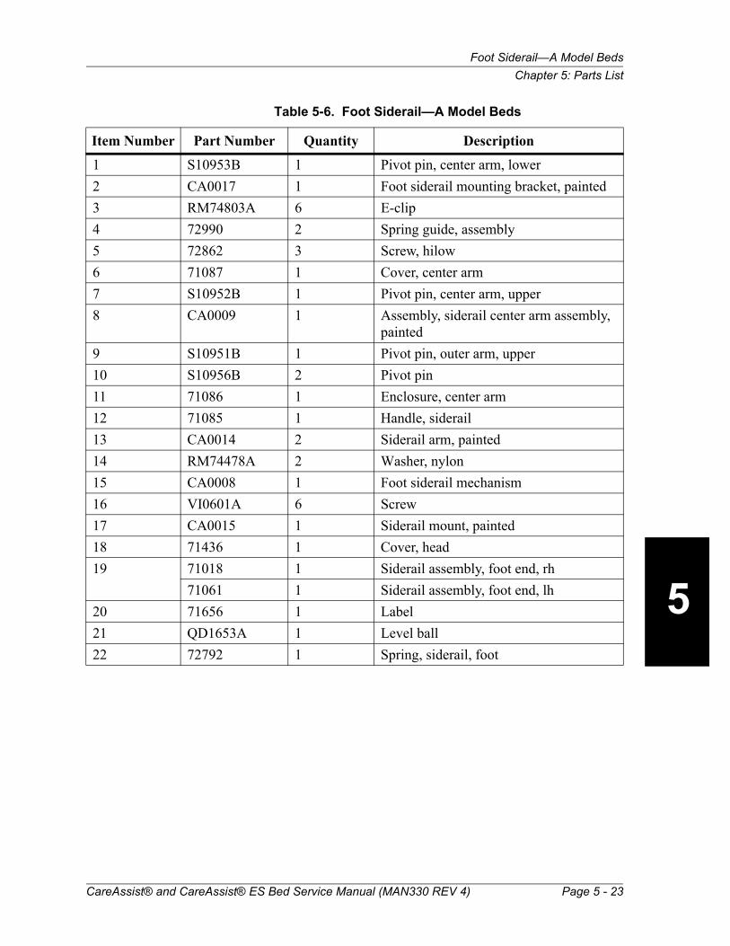
Foot Siderail—A Model Beds Chapter 5: Parts List
Table 5-6. Foot Siderail—A Model Beds
Item Number Part Number Quantity Description
1 S10953B 1 Pivot pin, center arm, lower 2 CA0017 1 Foot siderail mounting bracket, painted 3 RM74803A 6 E-clip 4 72990 2 Spring guide, assembly 5 72862 3 Screw, hilow 6 71087 1 Cover, center arm 7 S10952B 1 Pivot pin, center arm, upper 8 CA0009 1 Assembly, siderail center arm assembly,
painted 9 S10951B 1 Pivot pin, outer arm, upper 10 S10956B 2 Pivot pin 11 71086 1 Enclosure, center arm 12 71085 1 Handle, siderail 13 CA0014 2 Siderail arm, painted 14 RM74478A 2 Washer, nylon 15 CA0008 1 Foot siderail mechanism 16 VI0601A 6 Screw 17 CA0015 1 Siderail mount, painted 18 71436 1 Cover, head 19 71018 1 Siderail assembly, foot end, rh
71061 1 Siderail assembly, foot end, lh 20 71656 1 Label 21 QD1653A 1 Level ball 22 72792 1 Spring, siderail, foot
5
CareAssist® and CareAssist® ES Bed Service Manual (MAN330 REV 4) Page 5 - 23
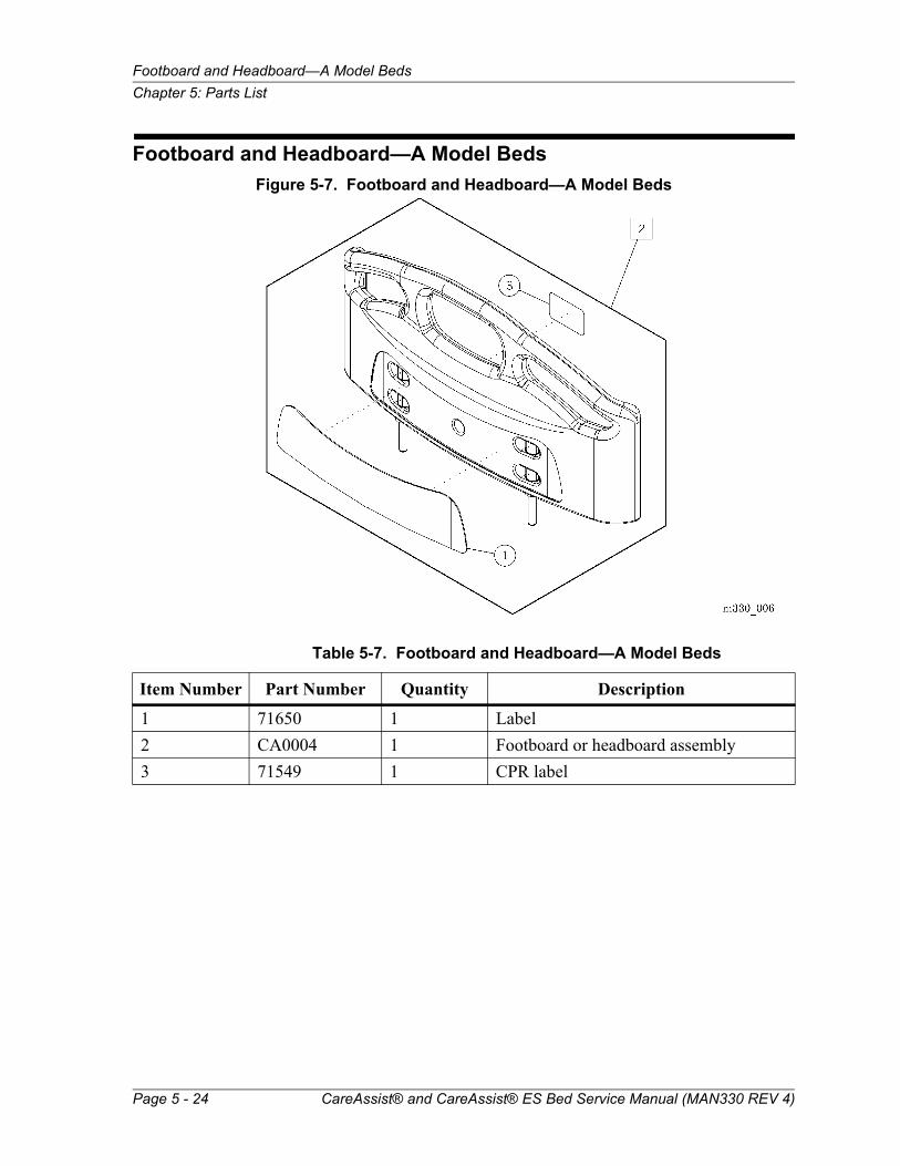
Footboard and Headboard—A Model Beds Chapter 5: Parts List
Footboard and Headboard—A Model Beds Figure 5-7. Footboard and Headboard—A Model Beds
Table 5-7. Footboard and Headboard—A Model Beds
Item Number Part Number Quantity Description
1 71650 1 Label 2 CA0004 1 Footboard or headboard assembly 3 71549 1 CPR label
Page 5 - 24 CareAssist® and CareAssist® ES Bed Service Manual (MAN330 REV 4)
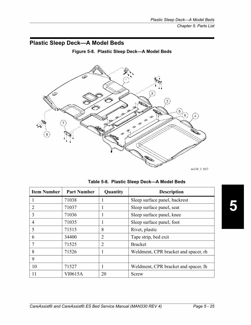
Plastic Sleep Deck—A Model Beds Chapter 5: Parts List
Plastic Sleep Deck—A Model Beds Figure 5-8. Plastic Sleep Deck—A Model Beds
Table 5-8. Plastic Sleep Deck—A Model Beds
Item Number Part Number Quantity Description
1 71038 1 Sleep surface panel, backrest 2 71037 1 Sleep surface panel, seat 3 71036 1 Sleep surface panel, knee 4 71035 1 Sleep surface panel, foot 5 71515 8 Rivet, plastic 6 34400 2 Tape strip, bed exit 7 71525 2 Bracket 8 71526 1 Weldment, CPR bracket and spacer, rh 9 10 71527 1 Weldment, CPR bracket and spacer, lh 11 VI0615A 20 Screw
5
CareAssist® and CareAssist® ES Bed Service Manual (MAN330 REV 4) Page 5 - 25
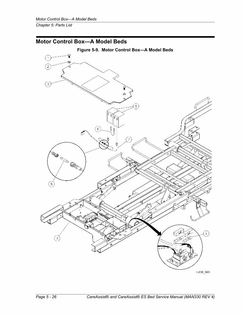
Motor Control Box—A Model Beds Chapter 5: Parts List
Motor Control Box—A Model Beds Figure 5-9. Motor Control Box—A Model Beds
Page 5 - 26 CareAssist® and CareAssist® ES Bed Service Manual (MAN330 REV 4)
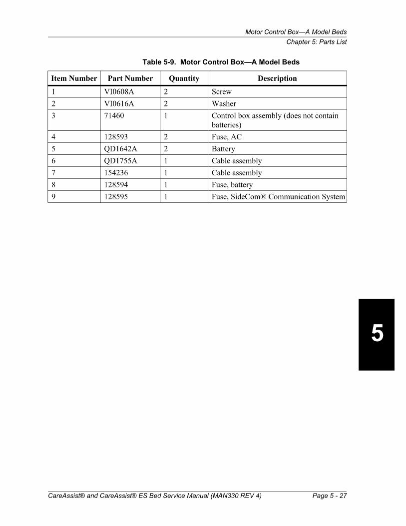
Motor Control Box—A Model Beds Chapter 5: Parts List
Table 5-9. Motor Control Box—A Model Beds
Item Number Part Number Quantity Description
1 VI0608A 2 Screw 2 VI0616A 2 Washer 3 71460 1 Control box assembly (does not contain
batteries) 4 128593 2 Fuse, AC 5 QD1642A 2 Battery 6 QD1755A 1 Cable assembly 7 154236 1 Cable assembly 8 128594 1 Fuse, battery 9 128595 1 Fuse, SideCom® Communication System
5
CareAssist® and CareAssist® ES Bed Service Manual (MAN330 REV 4) Page 5 - 27
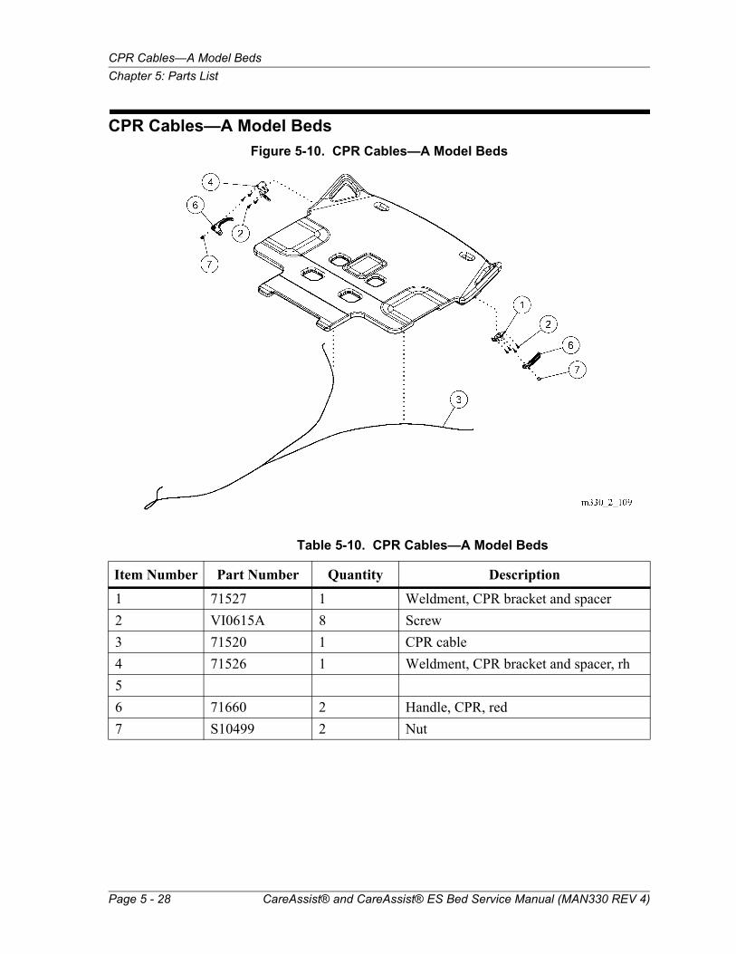
CPR Cables—A Model Beds Chapter 5: Parts List
CPR Cables—A Model Beds Figure 5-10. CPR Cables—A Model Beds
Table 5-10. CPR Cables—A Model Beds
Item Number Part Number Quantity Description
1 71527 1 Weldment, CPR bracket and spacer 2 VI0615A 8 Screw 3 71520 1 CPR cable 4 71526 1 Weldment, CPR bracket and spacer, rh 5 6 71660 2 Handle, CPR, red 7 S10499 2 Nut
Page 5 - 28 CareAssist® and CareAssist® ES Bed Service Manual (MAN330 REV 4)

CPR Cables—A Model Beds Chapter 5: Parts List
NOTES:
5
CareAssist® and CareAssist® ES Bed Service Manual (MAN330 REV 4) Page 5 - 29
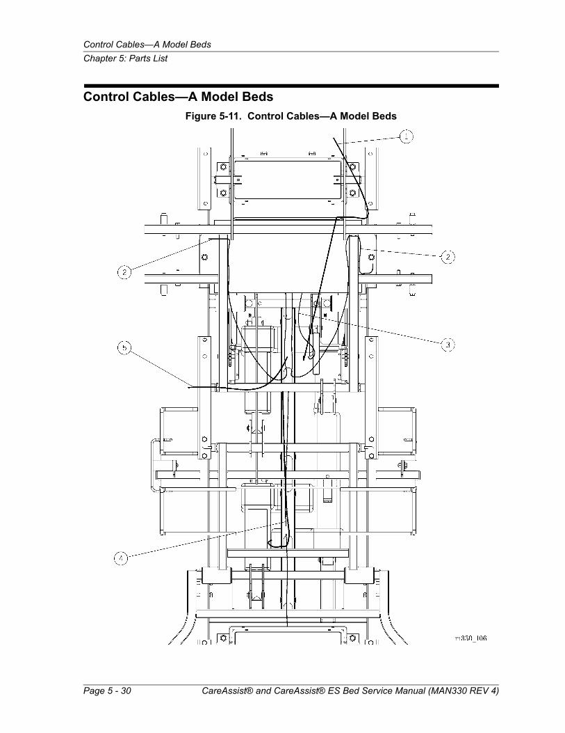
Control Cables—A Model Beds Chapter 5: Parts List
Control Cables—A Model Beds Figure 5-11. Control Cables—A Model Beds
Page 5 - 30 CareAssist® and CareAssist® ES Bed Service Manual (MAN330 REV 4)

Control Cables—A Model Beds Chapter 5: Parts List
Table 5-11. Control Cables—A Model Beds
Item Number Part Number Quantity Description
1 71459 1 SideCom® Communication System cable 2 71762 1 (per side) Siderail cable 3 71666 1 Interface P.C. board cable 4 QD1678G 1 Foot hilow column extension cable 5 71761 1 Pendant cable 6 (not shown) 71073 1 Pendant, without SideCom®
Communication System 7 (not shown) 72781 1 Pendant, with SideCom® Communica
tion System
5
CareAssist® and CareAssist® ES Bed Service Manual (MAN330 REV 4) Page 5 - 31
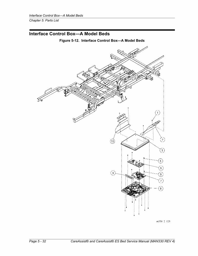
Interface Control Box—A Model Beds Chapter 5: Parts List
Interface Control Box—A Model Beds Figure 5-12. Interface Control Box—A Model Beds
Page 5 - 32 CareAssist® and CareAssist® ES Bed Service Manual (MAN330 REV 4)
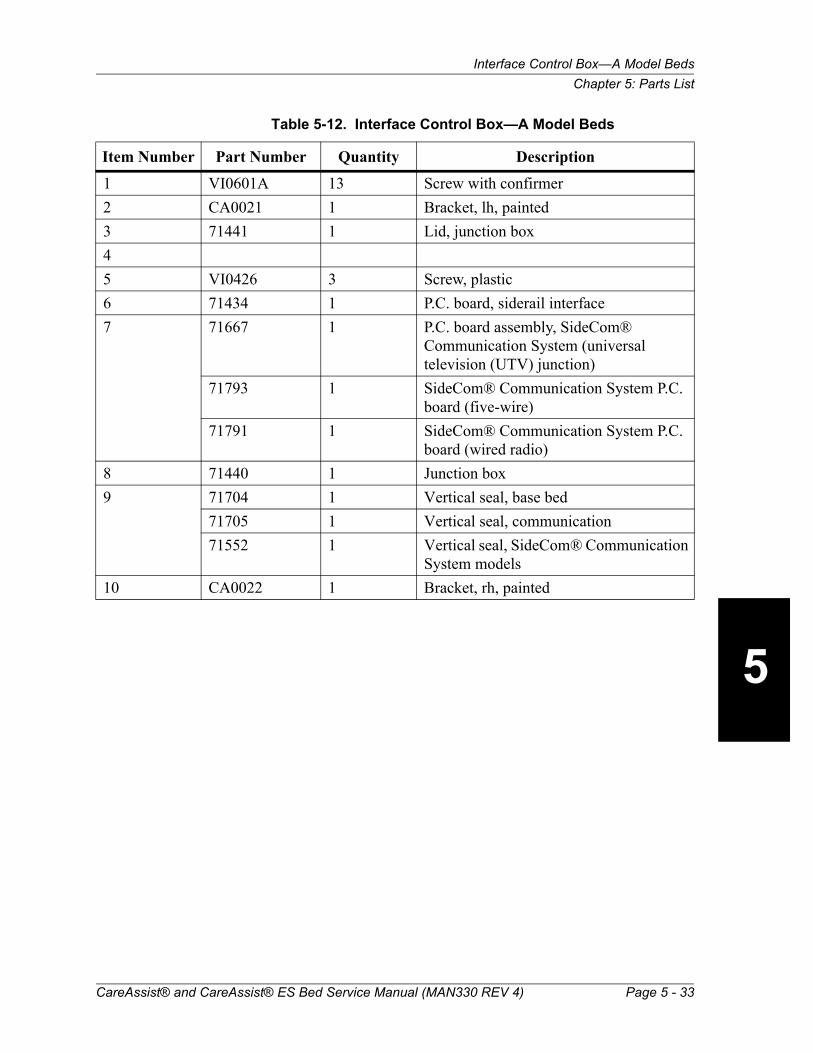
Interface Control Box—A Model Beds Chapter 5: Parts List
Table 5-12. Interface Control Box—A Model Beds
Item Number Part Number Quantity Description
1 VI0601A 13 Screw with confirmer 2 CA0021 1 Bracket, lh, painted 3 71441 1 Lid, junction box 4 5 VI0426 3 Screw, plastic 6 71434 1 P.C. board, siderail interface 7 71667 1 P.C. board assembly, SideCom®
Communication System (universal television (UTV) junction)
71793 1 SideCom® Communication System P.C. board (five-wire)
71791 1 SideCom® Communication System P.C. board (wired radio)
8 71440 1 Junction box 9 71704 1 Vertical seal, base bed
71705 1 Vertical seal, communication 71552 1 Vertical seal, SideCom® Communication
System models 10 CA0022 1 Bracket, rh, painted
5
CareAssist® and CareAssist® ES Bed Service Manual (MAN330 REV 4) Page 5 - 33
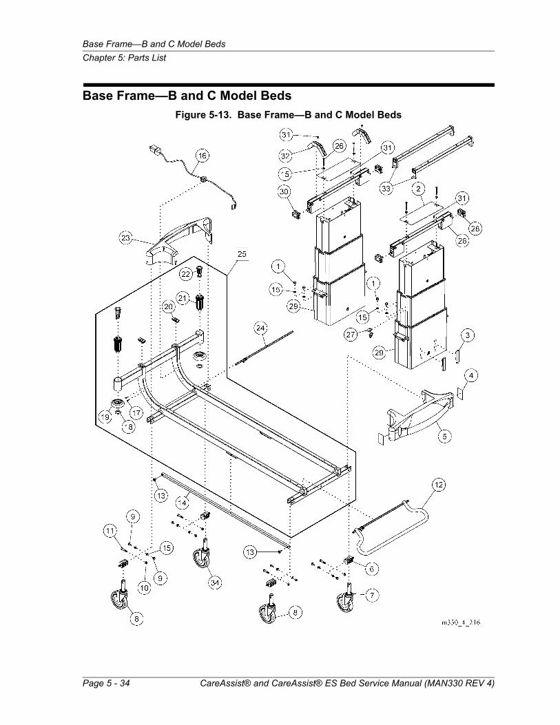
Base Frame—B and C Model Beds Chapter 5: Parts List
Base Frame—B and C Model Beds Figure 5-13. Base Frame—B and C Model Beds
Page 5 - 34 CareAssist® and CareAssist® ES Bed Service Manual (MAN330 REV 4)
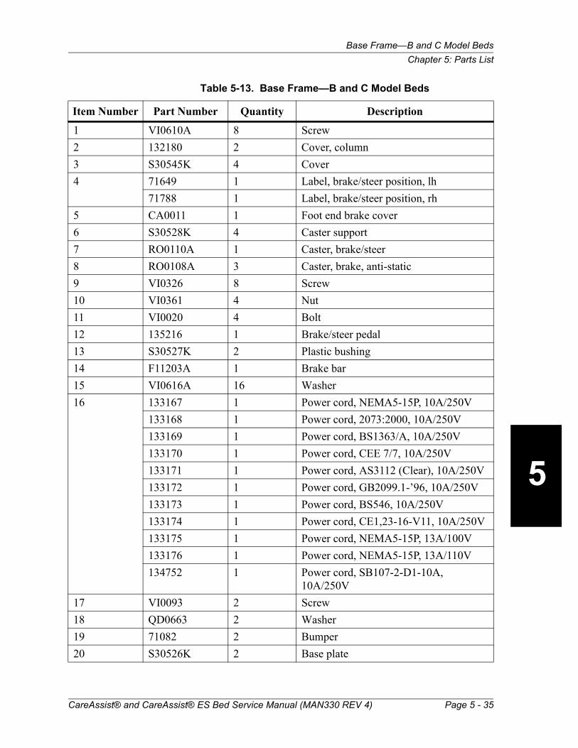
Base Frame—B and C Model Beds Chapter 5: Parts List
Table 5-13. Base Frame—B and C Model Beds
Item Number Part Number Quantity Description
1 VI0610A 8 Screw 2 132180 2 Cover, column 3 S30545K 4 Cover 4 71649 1 Label, brake/steer position, lh
71788 1 Label, brake/steer position, rh 5 CA0011 1 Foot end brake cover 6 S30528K 4 Caster support 7 RO0110A 1 Caster, brake/steer 8 RO0108A 3 Caster, brake, anti-static 9 VI0326 8 Screw 10 VI0361 4 Nut 11 VI0020 4 Bolt 12 135216 1 Brake/steer pedal 13 S30527K 2 Plastic bushing 14 F11203A 1 Brake bar 15 VI0616A 16 Washer 16 133167 1 Power cord, NEMA5-15P, 10A/250V
133168 1 Power cord, 2073:2000, 10A/250V 133169 1 Power cord, BS1363/A, 10A/250V 133170 1 Power cord, CEE 7/7, 10A/250V 133171 1 Power cord, AS3112 (Clear), 10A/250V 133172 1 Power cord, GB2099.1-’96, 10A/250V 133173 1 Power cord, BS546, 10A/250V 133174 1 Power cord, CE1,23-16-V11, 10A/250V 133175 1 Power cord, NEMA5-15P, 13A/100V 133176 1 Power cord, NEMA5-15P, 13A/110V 134752 1 Power cord, SB107-2-D1-10A,
10A/250V 17 VI0093 2 Screw 18 QD0663 2 Washer 19 71082 2 Bumper 20 S30526K 2 Base plate
5
CareAssist® and CareAssist® ES Bed Service Manual (MAN330 REV 4) Page 5 - 35
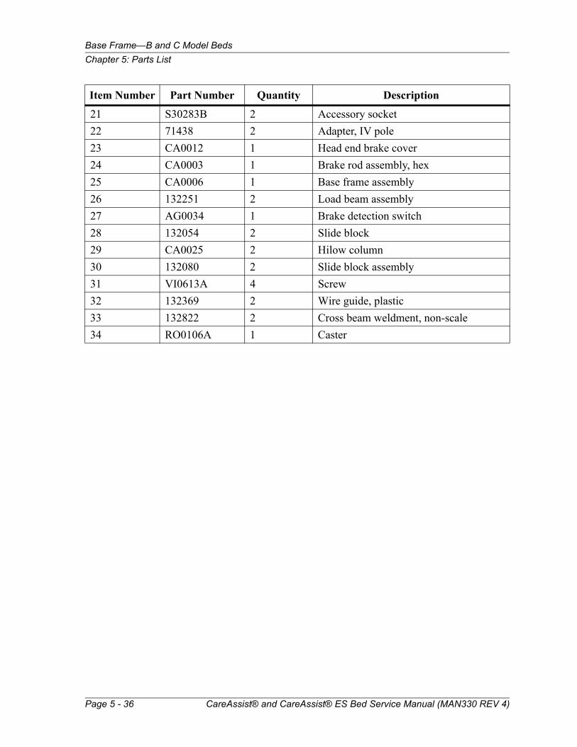
Base Frame—B and C Model Beds Chapter 5: Parts List
Item Number Part Number Quantity Description
21 S30283B 2 Accessory socket 22 71438 2 Adapter, IV pole 23 CA0012 1 Head end brake cover 24 CA0003 1 Brake rod assembly, hex 25 CA0006 1 Base frame assembly 26 132251 2 Load beam assembly 27 AG0034 1 Brake detection switch 28 132054 2 Slide block 29 CA0025 2 Hilow column 30 132080 2 Slide block assembly 31 VI0613A 4 Screw 32 132369 2 Wire guide, plastic 33 132822 2 Cross beam weldment, non-scale 34 RO0106A 1 Caster
Page 5 - 36 CareAssist® and CareAssist® ES Bed Service Manual (MAN330 REV 4)

Base Frame—B and C Model Beds Chapter 5: Parts List
NOTES:
5
CareAssist® and CareAssist® ES Bed Service Manual (MAN330 REV 4) Page 5 - 37
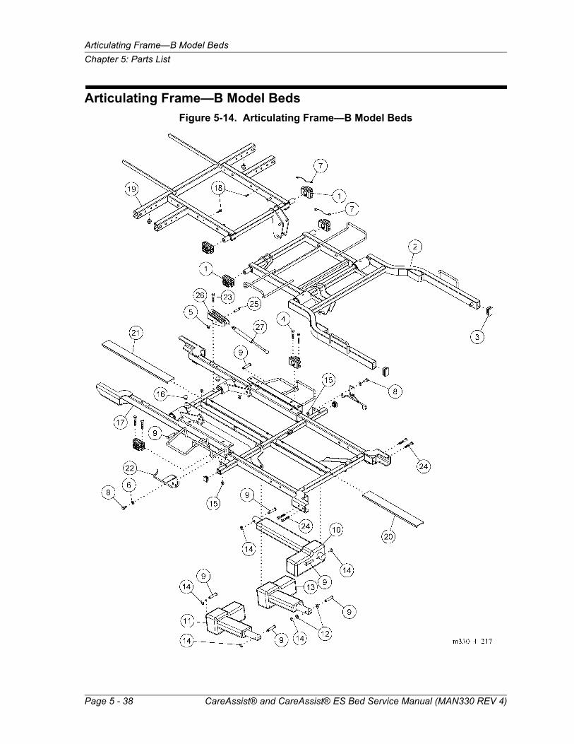
Articulating Frame—B Model Beds Chapter 5: Parts List
Articulating Frame—B Model Beds Figure 5-14. Articulating Frame—B Model Beds
Page 5 - 38 CareAssist® and CareAssist® ES Bed Service Manual (MAN330 REV 4)
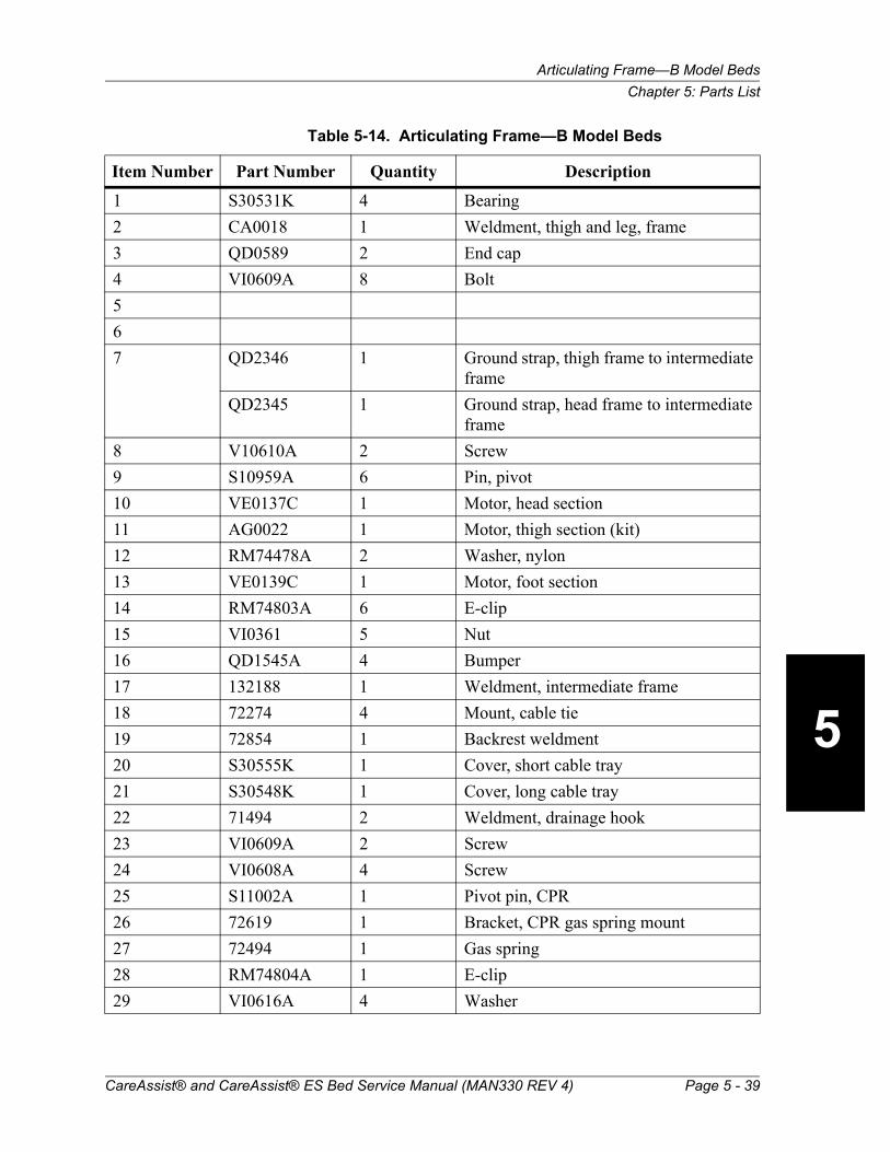
Articulating Frame—B Model Beds Chapter 5: Parts List
Table 5-14. Articulating Frame—B Model Beds
Item Number Part Number Quantity Description
1 S30531K 4 Bearing 2 CA0018 1 Weldment, thigh and leg, frame 3 QD0589 2 End cap 4 VI0609A 8 Bolt 5 6 7 QD2346 1 Ground strap, thigh frame to intermediate
frame QD2345 1 Ground strap, head frame to intermediate
frame 8 V10610A 2 Screw 9 S10959A 6 Pin, pivot 10 VE0137C 1 Motor, head section 11 AG0022 1 Motor, thigh section (kit) 12 RM74478A 2 Washer, nylon 13 VE0139C 1 Motor, foot section 14 RM74803A 6 E-clip 15 VI0361 5 Nut 16 QD1545A 4 Bumper 17 132188 1 Weldment, intermediate frame 18 72274 4 Mount, cable tie 19 72854 1 Backrest weldment 20 S30555K 1 Cover, short cable tray 21 S30548K 1 Cover, long cable tray 22 71494 2 Weldment, drainage hook 23 VI0609A 2 Screw 24 VI0608A 4 Screw 25 S11002A 1 Pivot pin, CPR 26 72619 1 Bracket, CPR gas spring mount 27 72494 1 Gas spring 28 RM74804A 1 E-clip 29 VI0616A 4 Washer
5
CareAssist® and CareAssist® ES Bed Service Manual (MAN330 REV 4) Page 5 - 39
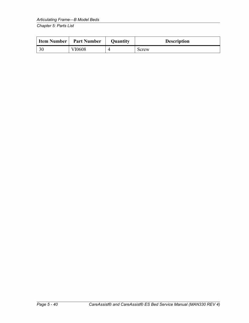
Articulating Frame—B Model Beds Chapter 5: Parts List
Item Number Part Number Quantity Description
30 VI0608 4 Screw
Page 5 - 40 CareAssist® and CareAssist® ES Bed Service Manual (MAN330 REV 4)

Articulating Frame—B Model Beds Chapter 5: Parts List
NOTES:
5
CareAssist® and CareAssist® ES Bed Service Manual (MAN330 REV 4) Page 5 - 41

Foot Extension—B Model Beds Chapter 5: Parts List
Foot Extension—B Model Beds Figure 5-15. Foot Extension—B Model Beds
Page 5 - 42 CareAssist® and CareAssist® ES Bed Service Manual (MAN330 REV 4)
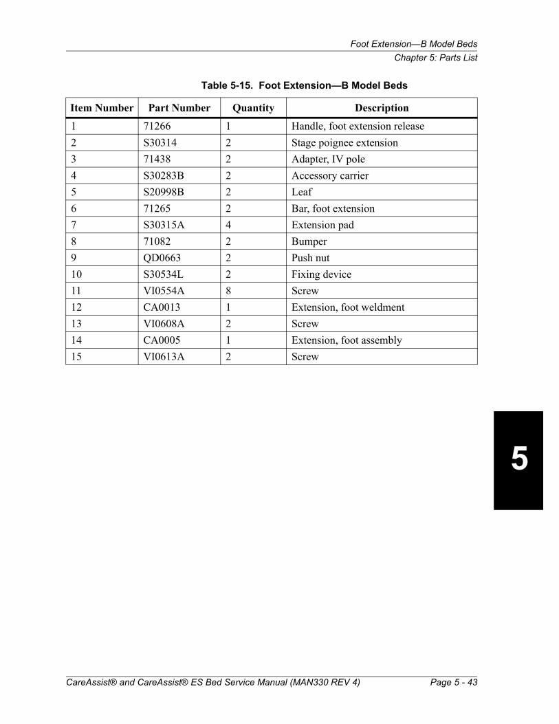
Foot Extension—B Model Beds Chapter 5: Parts List
Table 5-15. Foot Extension—B Model Beds
Item Number Part Number Quantity Description
1 71266 1 Handle, foot extension release 2 S30314 2 Stage poignee extension 3 71438 2 Adapter, IV pole 4 S30283B 2 Accessory carrier 5 S20998B 2 Leaf 6 71265 2 Bar, foot extension 7 S30315A 4 Extension pad 8 71082 2 Bumper 9 QD0663 2 Push nut 10 S30534L 2 Fixing device 11 VI0554A 8 Screw 12 CA0013 1 Extension, foot weldment 13 VI0608A 2 Screw 14 CA0005 1 Extension, foot assembly 15 VI0613A 2 Screw
5
CareAssist® and CareAssist® ES Bed Service Manual (MAN330 REV 4) Page 5 - 43
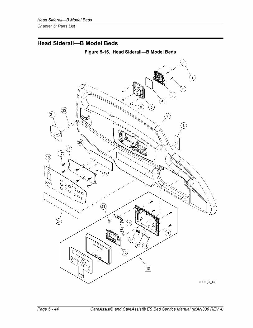
Head Siderail—B Model Beds Chapter 5: Parts List
Head Siderail—B Model Beds Figure 5-16. Head Siderail—B Model Beds
Page 5 - 44 CareAssist® and CareAssist® ES Bed Service Manual (MAN330 REV 4)

Head Siderail—B Model Beds Chapter 5: Parts List
Table 5-16. Head Siderail—B Model Beds
Item Number Part Number Quantity Description
1 72290 1 Label, blank, speaker cover 2 72862 4 or 8 Screw hi-lo 3 71090 1 Speaker cover 4 71091 1 Gasket, cover 5 70746 1 Speaker 6 28562 4 Nut 7 128804 1 Siderail, rh (scale beds)
129656 1 Siderail, lh (scale beds) 71019 1 Siderail, rh (non-scale beds) 71062 1 Siderail, lh (non-scale beds)
8 71536 1 Membrane switch, nurse call 72290 1 Labels, nurse call, speaker, blank
9 4214102 4 Screw 10 131573 1 Scale display, with bed exit, rh
128803 1 Scale display, with bed exit, lh 131572 1 Scale display, without bed exit, rh 131571 1 Scale display, without bed exit, lh 138231 1 Scale display, PPM, rh 138230 1 Scale display, PPM, lh 138233 1 Display, PPM only, rh 138232 1 Display, PPM only, lh
11 131724 1 Display axel, weldment, short, lh 129658 1 Display axel, weldment, long, rh
12 129441 1 Pivot insert 13 49199 1 Spring 14 73004 1 Cable assembly 15 133197 1 Assembly, scale display P.C. board
5
CareAssist® and CareAssist® ES Bed Service Manual (MAN330 REV 4) Page 5 - 45
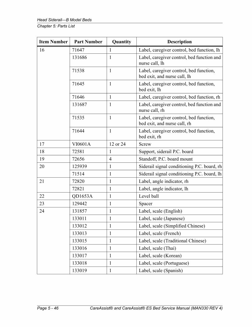
Head Siderail—B Model Beds Chapter 5: Parts List
Item Number Part Number Quantity Description
16 71647 1 Label, caregiver control, bed function, lh 131686 1 Label, caregiver control, bed function and
nurse call, lh 71538 1 Label, caregiver control, bed function,
bed exit, and nurse call, lh 71645 1 Label, caregiver control, bed function,
bed exit, lh 71646 1 Label, caregiver control, bed function, rh 131687 1 Label, caregiver control, bed function and
nurse call, rh 71535 1 Label, caregiver control, bed function,
bed exit, and nurse call, rh 71644 1 Label, caregiver control, bed function,
bed exit, rh 17 VI0601A 12 or 24 Screw 18 72581 1 Support, siderail P.C. board 19 72656 4 Standoff, P.C. board mount 20 125939 1 Siderail signal conditioning P.C. board, rh
71514 1 Siderail signal conditioning P.C. board, lh 21 72820 1 Label, angle indicator, rh
72821 1 Label, angle indicator, lh 22 QD1653A 1 Level ball 23 129442 1 Spacer 24 131857 1 Label, scale (English)
133011 1 Label, scale (Japanese) 133012 1 Label, scale (Simplified Chinese) 133013 1 Label, scale (French) 133015 1 Label, scale (Traditional Chinese) 133016 1 Label, scale (Thai) 133017 1 Label, scale (Korean) 133018 1 Label, scale (Portuguese) 133019 1 Label, scale (Spanish)
Page 5 - 46 CareAssist® and CareAssist® ES Bed Service Manual (MAN330 REV 4)

Head Siderail—B Model Beds Chapter 5: Parts List
NOTES:
5
CareAssist® and CareAssist® ES Bed Service Manual (MAN330 REV 4) Page 5 - 47
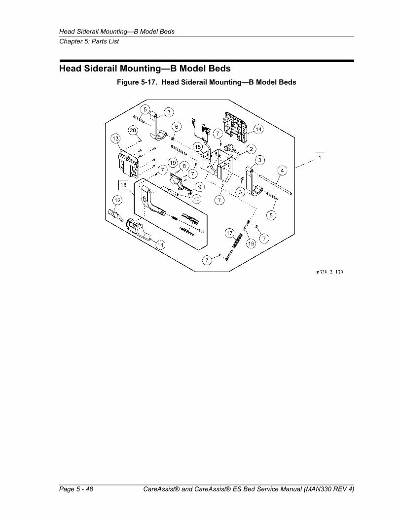
Head Siderail Mounting—B Model Beds Chapter 5: Parts List
Head Siderail Mounting—B Model Beds Figure 5-17. Head Siderail Mounting—B Model Beds
Page 5 - 48 CareAssist® and CareAssist® ES Bed Service Manual (MAN330 REV 4)
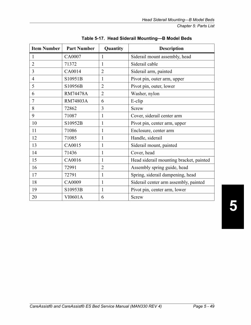
Head Siderail Mounting—B Model Beds Chapter 5: Parts List
Table 5-17. Head Siderail Mounting—B Model Beds
Item Number Part Number Quantity Description
1 CA0007 1 Siderail mount assembly, head 2 71372 1 Siderail cable 3 CA0014 2 Siderail arm, painted 4 S10951B 1 Pivot pin, outer arm, upper 5 S10956B 2 Pivot pin, outer, lower 6 RM74478A 2 Washer, nylon 7 RM74803A 6 E-clip 8 72862 3 Screw 9 71087 1 Cover, siderail center arm 10 S10952B 1 Pivot pin, center arm, upper 11 71086 1 Enclosure, center arm 12 71085 1 Handle, siderail 13 CA0015 1 Siderail mount, painted 14 71436 1 Cover, head 15 CA0016 1 Head siderail mounting bracket, painted 16 72991 2 Assembly spring guide, head 17 72791 1 Spring, siderail dampening, head 18 CA0009 1 Siderail center arm assembly, painted 19 S10953B 1 Pivot pin, center arm, lower 20 VI0601A 6 Screw
5
CareAssist® and CareAssist® ES Bed Service Manual (MAN330 REV 4) Page 5 - 49
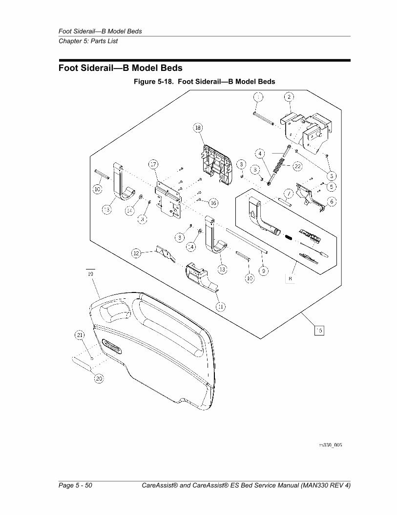
Foot Siderail—B Model Beds Chapter 5: Parts List
Foot Siderail—B Model Beds Figure 5-18. Foot Siderail—B Model Beds
Page 5 - 50 CareAssist® and CareAssist® ES Bed Service Manual (MAN330 REV 4)
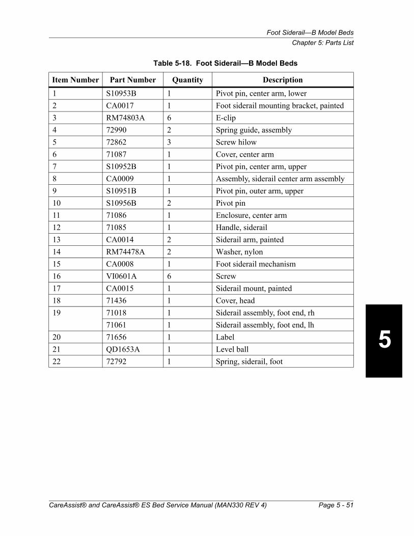
Foot Siderail—B Model Beds Chapter 5: Parts List
Table 5-18. Foot Siderail—B Model Beds
Item Number Part Number Quantity Description
1 S10953B 1 Pivot pin, center arm, lower 2 CA0017 1 Foot siderail mounting bracket, painted 3 RM74803A 6 E-clip 4 72990 2 Spring guide, assembly 5 72862 3 Screw hilow 6 71087 1 Cover, center arm 7 S10952B 1 Pivot pin, center arm, upper 8 CA0009 1 Assembly, siderail center arm assembly 9 S10951B 1 Pivot pin, outer arm, upper 10 S10956B 2 Pivot pin 11 71086 1 Enclosure, center arm 12 71085 1 Handle, siderail 13 CA0014 2 Siderail arm, painted 14 RM74478A 2 Washer, nylon 15 CA0008 1 Foot siderail mechanism 16 VI0601A 6 Screw 17 CA0015 1 Siderail mount, painted 18 71436 1 Cover, head 19 71018 1 Siderail assembly, foot end, rh
71061 1 Siderail assembly, foot end, lh 20 71656 1 Label 21 QD1653A 1 Level ball 22 72792 1 Spring, siderail, foot
5
CareAssist® and CareAssist® ES Bed Service Manual (MAN330 REV 4) Page 5 - 51
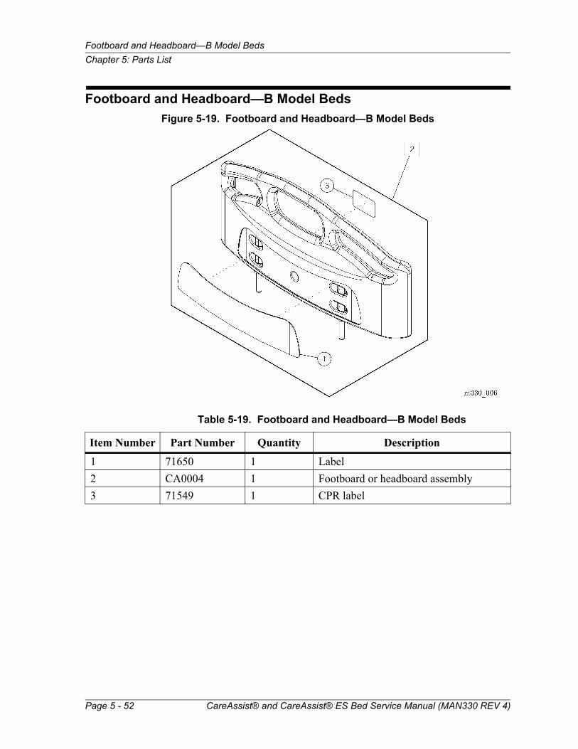
Footboard and Headboard—B Model Beds Chapter 5: Parts List
Footboard and Headboard—B Model Beds Figure 5-19. Footboard and Headboard—B Model Beds
Table 5-19. Footboard and Headboard—B Model Beds
Item Number Part Number Quantity Description
1 71650 1 Label 2 CA0004 1 Footboard or headboard assembly 3 71549 1 CPR label
Page 5 - 52 CareAssist® and CareAssist® ES Bed Service Manual (MAN330 REV 4)

Plastic Sleep Deck—B Model Beds Chapter 5: Parts List
Plastic Sleep Deck—B Model Beds Figure 5-20. Plastic Sleep Deck—B Model Beds
Table 5-20. Plastic Sleep Deck—B Model Beds
Item Number Part Number Quantity Description
1 135264 1 Sleep surface panel, backrest 2 71037 1 Sleep surface panel, seat 3 71036 1 Sleep surface panel, knee 4 71035 1 Sleep surface panel, foot 5 71515 8 Rivet, plastic 6 34400 2 Tape strip, bed exit
5
CareAssist® and CareAssist® ES Bed Service Manual (MAN330 REV 4) Page 5 - 53
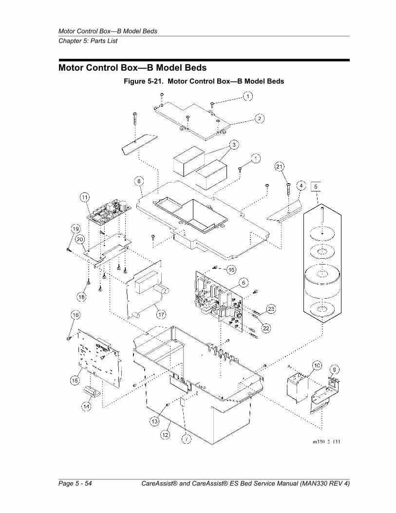
Motor Control Box—B Model Beds Chapter 5: Parts List
Motor Control Box—B Model Beds Figure 5-21. Motor Control Box—B Model Beds
Page 5 - 54 CareAssist® and CareAssist® ES Bed Service Manual (MAN330 REV 4)
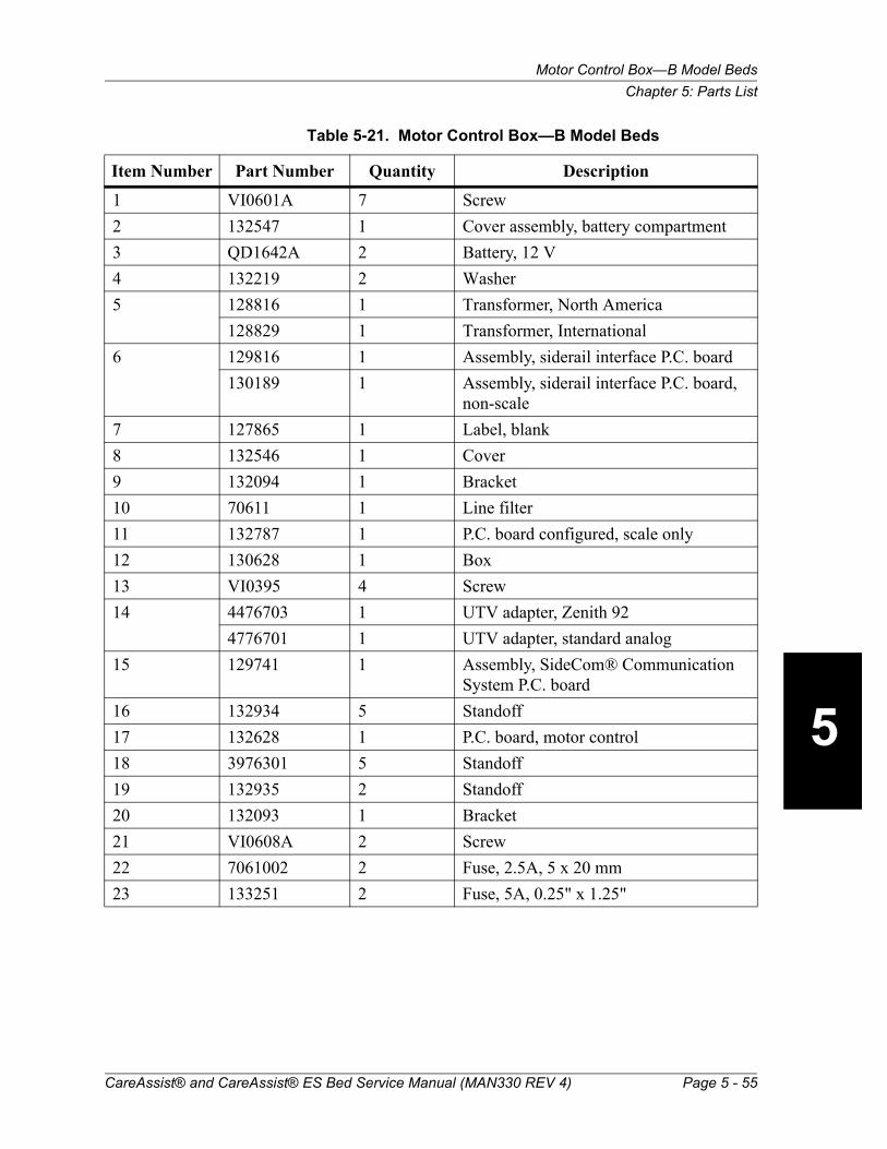
Motor Control Box—B Model Beds Chapter 5: Parts List
Table 5-21. Motor Control Box—B Model Beds
Item Number Part Number Quantity Description
1 VI0601A 7 Screw 2 132547 1 Cover assembly, battery compartment 3 QD1642A 2 Battery, 12 V 4 132219 2 Washer 5 128816 1 Transformer, North America
128829 1 Transformer, International 6 129816 1 Assembly, siderail interface P.C. board
130189 1 Assembly, siderail interface P.C. board, non-scale
7 127865 1 Label, blank 8 132546 1 Cover 9 132094 1 Bracket 10 70611 1 Line filter 11 132787 1 P.C. board configured, scale only 12 130628 1 Box 13 VI0395 4 Screw 14 4476703 1 UTV adapter, Zenith 92
4776701 1 UTV adapter, standard analog 15 129741 1 Assembly, SideCom® Communication
System P.C. board 16 132934 5 Standoff 17 132628 1 P.C. board, motor control 18 3976301 5 Standoff 19 132935 2 Standoff 20 132093 1 Bracket 21 VI0608A 2 Screw 22 7061002 2 Fuse, 2.5A, 5 x 20 mm 23 133251 2 Fuse, 5A, 0.25" x 1.25"
5
CareAssist® and CareAssist® ES Bed Service Manual (MAN330 REV 4) Page 5 - 55
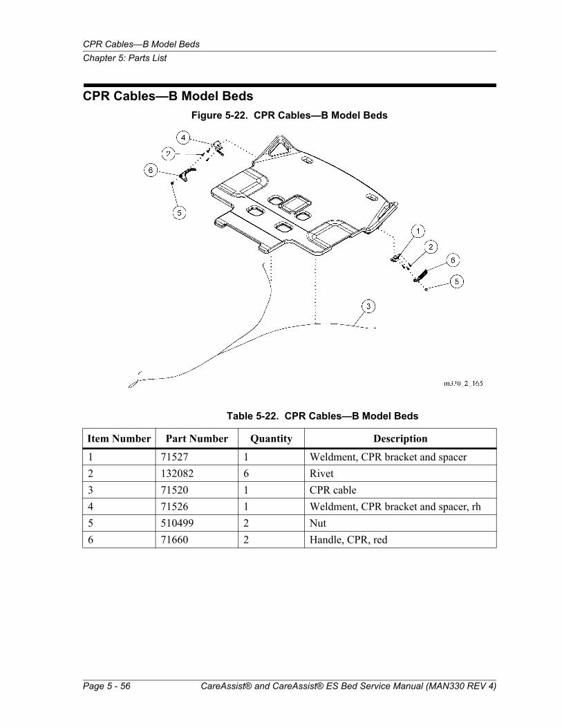
CPR Cables—B Model Beds Chapter 5: Parts List
CPR Cables—B Model Beds Figure 5-22. CPR Cables—B Model Beds
Table 5-22. CPR Cables—B Model Beds
Item Number Part Number Quantity Description
1 71527 1 Weldment, CPR bracket and spacer 2 132082 6 Rivet 3 71520 1 CPR cable 4 71526 1 Weldment, CPR bracket and spacer, rh 5 510499 2 Nut 6 71660 2 Handle, CPR, red
Page 5 - 56 CareAssist® and CareAssist® ES Bed Service Manual (MAN330 REV 4)
CPR Cables—B Model Beds Chapter 5: Parts List
NOTES:
5
CareAssist® and CareAssist® ES Bed Service Manual (MAN330 REV 4) Page 5 - 57
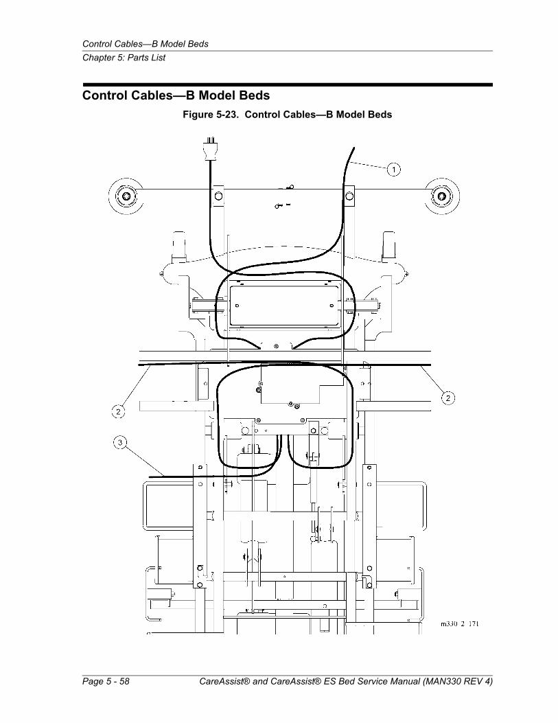
Control Cables—B Model Beds Chapter 5: Parts List
Control Cables—B Model Beds Figure 5-23. Control Cables—B Model Beds
Page 5 - 58 CareAssist® and CareAssist® ES Bed Service Manual (MAN330 REV 4)
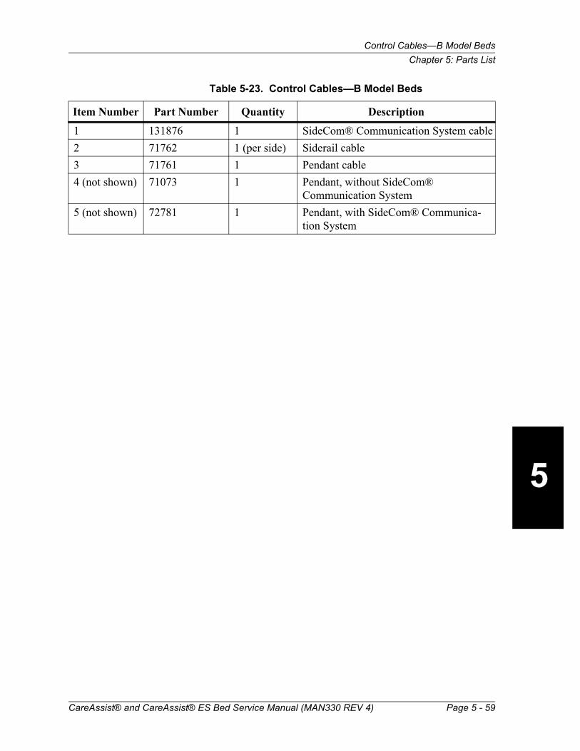
Control Cables—B Model Beds Chapter 5: Parts List
Table 5-23. Control Cables—B Model Beds
Item Number Part Number Quantity Description
1 131876 1 SideCom® Communication System cable 2 71762 1 (per side) Siderail cable 3 71761 1 Pendant cable 4 (not shown) 71073 1 Pendant, without SideCom®
Communication System 5 (not shown) 72781 1 Pendant, with SideCom® Communica
tion System
5
CareAssist® and CareAssist® ES Bed Service Manual (MAN330 REV 4) Page 5 - 59
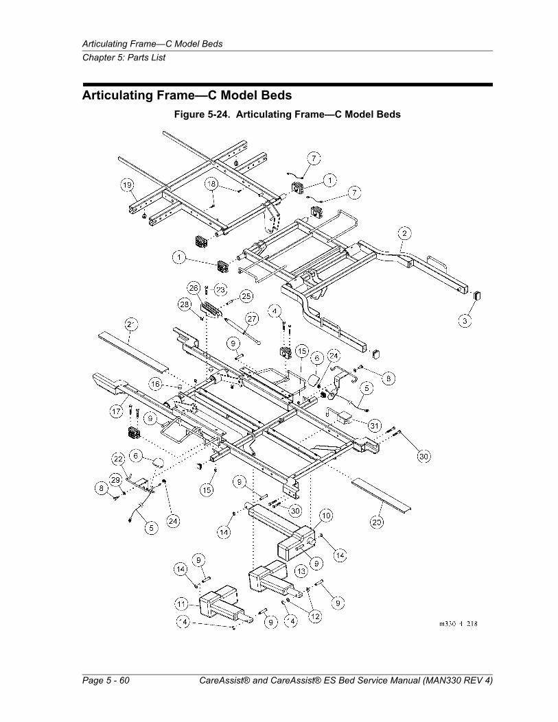
Articulating Frame—C Model Beds Chapter 5: Parts List
Articulating Frame—C Model Beds Figure 5-24. Articulating Frame—C Model Beds
Page 5 - 60 CareAssist® and CareAssist® ES Bed Service Manual (MAN330 REV 4)
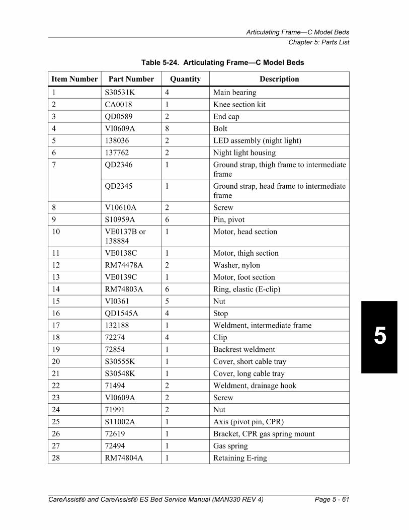
Articulating Frame—C Model Beds Chapter 5: Parts List
Table 5-24. Articulating Frame—C Model Beds
Item Number Part Number Quantity Description
1 S30531K 4 Main bearing 2 CA0018 1 Knee section kit 3 QD0589 2 End cap 4 VI0609A 8 Bolt 5 138036 2 LED assembly (night light) 6 137762 2 Night light housing 7 QD2346 1 Ground strap, thigh frame to intermediate
frame QD2345 1 Ground strap, head frame to intermediate
frame 8 V10610A 2 Screw 9 S10959A 6 Pin, pivot 10 VE0137B or
138884 1 Motor, head section
11 VE0138C 1 Motor, thigh section 12 RM74478A 2 Washer, nylon 13 VE0139C 1 Motor, foot section 14 RM74803A 6 Ring, elastic (E-clip) 15 VI0361 5 Nut 16 QD1545A 4 Stop 17 132188 1 Weldment, intermediate frame 18 72274 4 Clip 19 72854 1 Backrest weldment 20 S30555K 1 Cover, short cable tray 21 S30548K 1 Cover, long cable tray 22 71494 2 Weldment, drainage hook 23 VI0609A 2 Screw 24 71991 2 Nut 25 S11002A 1 Axis (pivot pin, CPR) 26 72619 1 Bracket, CPR gas spring mount 27 72494 1 Gas spring 28 RM74804A 1 Retaining E-ring
5
CareAssist® and CareAssist® ES Bed Service Manual (MAN330 REV 4) Page 5 - 61
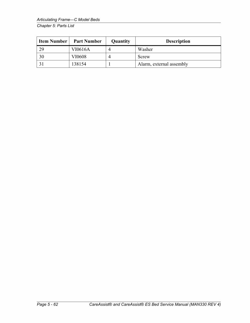
Articulating Frame—C Model Beds Chapter 5: Parts List
Item Number Part Number Quantity Description
29 VI0616A 4 Washer 30 VI0608 4 Screw 31 138154 1 Alarm, external assembly
Page 5 - 62 CareAssist® and CareAssist® ES Bed Service Manual (MAN330 REV 4)

Articulating Frame—C Model Beds Chapter 5: Parts List
NOTES:
5
CareAssist® and CareAssist® ES Bed Service Manual (MAN330 REV 4) Page 5 - 63
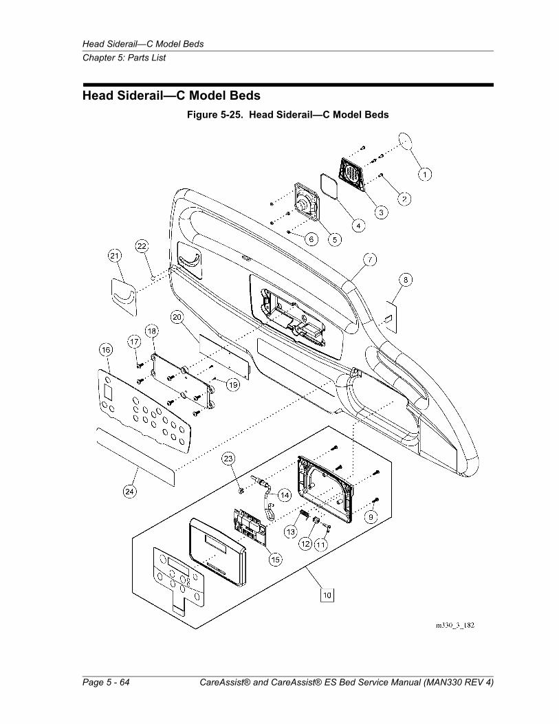
Head Siderail—C Model Beds Chapter 5: Parts List
Head Siderail—C Model Beds Figure 5-25. Head Siderail—C Model Beds
Page 5 - 64 CareAssist® and CareAssist® ES Bed Service Manual (MAN330 REV 4)
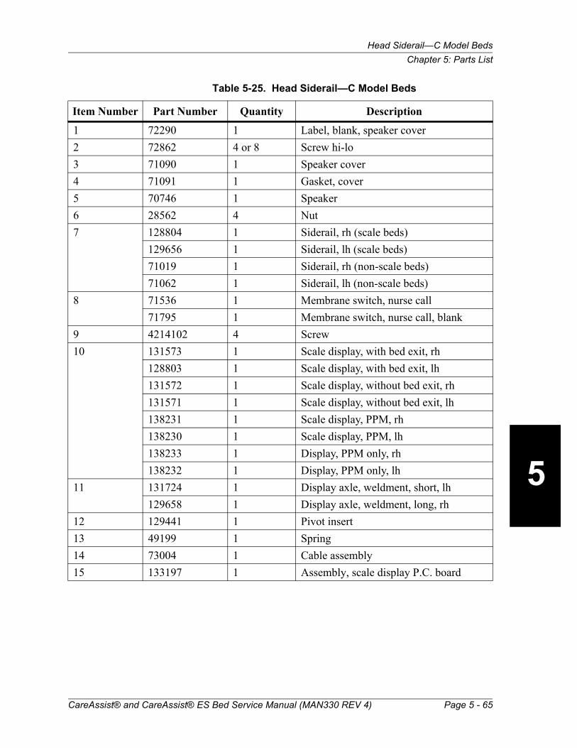
Head Siderail—C Model Beds Chapter 5: Parts List
Table 5-25. Head Siderail—C Model Beds
Item Number Part Number Quantity Description
1 72290 1 Label, blank, speaker cover 2 72862 4 or 8 Screw hi-lo 3 71090 1 Speaker cover 4 71091 1 Gasket, cover 5 70746 1 Speaker 6 28562 4 Nut 7 128804 1 Siderail, rh (scale beds)
129656 1 Siderail, lh (scale beds) 71019 1 Siderail, rh (non-scale beds) 71062 1 Siderail, lh (non-scale beds)
8 71536 1 Membrane switch, nurse call 71795 1 Membrane switch, nurse call, blank
9 4214102 4 Screw 10 131573 1 Scale display, with bed exit, rh
128803 1 Scale display, with bed exit, lh 131572 1 Scale display, without bed exit, rh 131571 1 Scale display, without bed exit, lh 138231 1 Scale display, PPM, rh 138230 1 Scale display, PPM, lh 138233 1 Display, PPM only, rh 138232 1 Display, PPM only, lh
11 131724 1 Display axle, weldment, short, lh 129658 1 Display axle, weldment, long, rh
12 129441 1 Pivot insert 13 49199 1 Spring 14 73004 1 Cable assembly 15 133197 1 Assembly, scale display P.C. board
5
CareAssist® and CareAssist® ES Bed Service Manual (MAN330 REV 4) Page 5 - 65

Head Siderail—C Model Beds Chapter 5: Parts List
Item Number Part Number Quantity Description
16 71647 1 Label, caregiver control, bed function, lh 131686 1 Label, caregiver control, bed function and
nurse call, lh 71538 1 Label, caregiver control, bed function,
bed exit, and nurse call, lh 71645 1 Label, caregiver control, bed function,
bed exit, lh 71646 1 Label, caregiver control, bed function, rh 131687 1 Label, caregiver control, bed function and
nurse call, rh 71535 1 Label, caregiver control, bed function,
bed exit, and nurse call, rh 71644 1 Label, caregiver control, bed function,
bed exit, rh 17 VI0601A 12 or 24 Screw 18 72581 1 Support, siderail P.C. board 19 72656 4 Standoff, P.C. board mount 20 125939 1 Siderail signal conditioning P.C. board, rh
71514 1 Siderail signal conditioning P.C. board, lh 21 72820 1 Label, angle indicator, rh
72821 1 Label, angle indicator, lh 22 QD1653A 1 Level ball 23 129442 1 Spacer 24 131857 1 Label, scale (English)
133011 1 Label, scale (Japanese) 133012 1 Label, scale (Simplified Chinese) 133013 1 Label, scale (French) 133015 1 Label, scale (Traditional Chinese) 133016 1 Label, scale (Thai) 133017 1 Label, scale (Korean) 133018 1 Label, scale (Portuguese) 133019 1 Label, scale (Spanish)
Page 5 - 66 CareAssist® and CareAssist® ES Bed Service Manual (MAN330 REV 4)

Head Siderail—C Model Beds Chapter 5: Parts List
NOTES:
5
CareAssist® and CareAssist® ES Bed Service Manual (MAN330 REV 4) Page 5 - 67
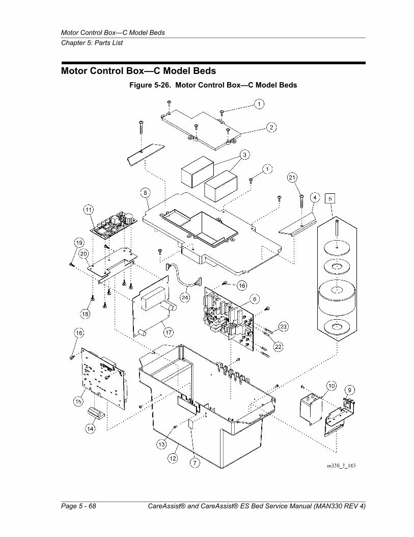
Motor Control Box—C Model Beds Chapter 5: Parts List
Motor Control Box—C Model Beds Figure 5-26. Motor Control Box—C Model Beds
Page 5 - 68 CareAssist® and CareAssist® ES Bed Service Manual (MAN330 REV 4)

Motor Control Box—C Model Beds Chapter 5: Parts List
Table 5-26. Motor Control Box—C Model Beds
Item Number Part Number Quantity Description
1 VI0601A 7 Screw 2 132547 1 Cover assembly, battery compartment 3 QD1642A 2 Battery, 12 V 4 132219 2 Washer 5 128816 1 Transformer, North America
128829 1 Transformer, International 6 137613 1 Assembly, siderail interface P.C. board 7 127865 1 Label, blank 8 132546 1 Battery compartment assembly 9 132094 1 Power cord mount 10 70611 1 Line filter 11 150139 1 P.C. board assy, scale and PPM, 400 lb
150140 1 P.C. board assy, PPM only, 400 lb 150141 1 P.C. board assy, scale only, 400 lb
12 130628 1 Electrical enclosure 13 VI0395 4 Screw 14 4476703 1 UTV adapter, Zenith 92
4476701 1 UTV adapter, standard analog 15 129741 1 SideCom® Communication System P.C.
board 133260 1 Assembly, SideCom® Communication
System P.C. board, non-UTV 16 132934 5 Circuit board support (standoff) 17 132628 1 P.C. board, motor control 18 3976301 5 Standoff 19 132935 2 Circuit board support (standoff) 20 132093 1 Scale board mount 21 VI0608A 2 Screw 22 7061002 2 Fuse, 2.5A, 5 x 20 mm 23 133251 2 Fuse, 5A, 0.25" x 1.25" 24 137692 1 Cable
5
CareAssist® and CareAssist® ES Bed Service Manual (MAN330 REV 4) Page 5 - 69
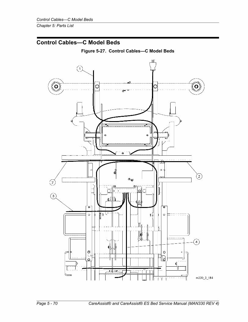
Control Cables—C Model Beds Chapter 5: Parts List
Control Cables—C Model Beds Figure 5-27. Control Cables—C Model Beds
Page 5 - 70 CareAssist® and CareAssist® ES Bed Service Manual (MAN330 REV 4)
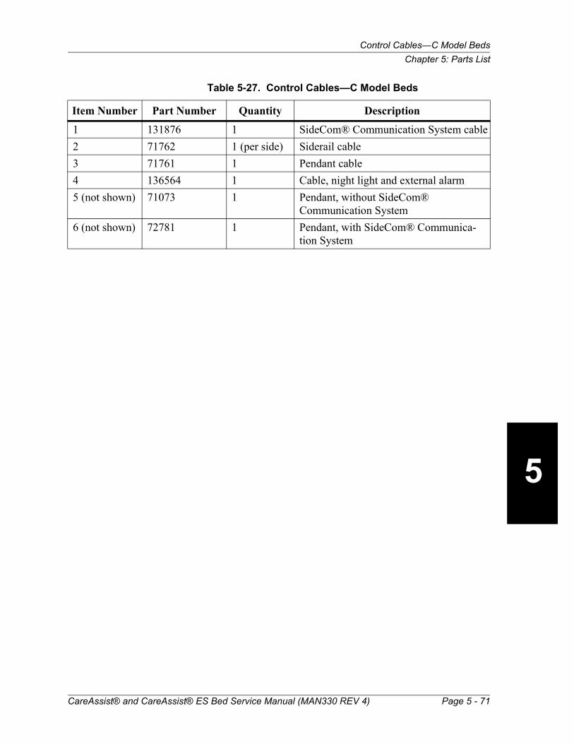
Control Cables—C Model Beds Chapter 5: Parts List
Table 5-27. Control Cables—C Model Beds
Item Number Part Number Quantity Description
1 131876 1 SideCom® Communication System cable 2 71762 1 (per side) Siderail cable 3 71761 1 Pendant cable 4 136564 1 Cable, night light and external alarm 5 (not shown) 71073 1 Pendant, without SideCom®
Communication System 6 (not shown) 72781 1 Pendant, with SideCom® Communica
tion System
5
CareAssist® and CareAssist® ES Bed Service Manual (MAN330 REV 4) Page 5 - 71
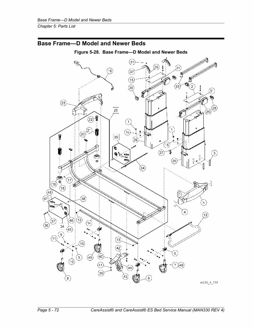
Base Frame—D Model and Newer Beds Chapter 5: Parts List
Base Frame—D Model and Newer Beds Figure 5-28. Base Frame—D Model and Newer Beds
Page 5 - 72 CareAssist® and CareAssist® ES Bed Service Manual (MAN330 REV 4)
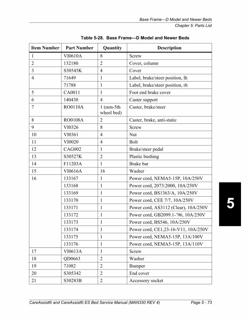
Base Frame—D Model and Newer Beds Chapter 5: Parts List
Table 5-28. Base Frame—D Model and Newer Beds
Item Number Part Number Quantity Description
1 VI0610A 8 Screw 2 132180 2 Cover, column 3 S30545K 4 Cover 4 71649 1 Label, brake/steer position, lh
71788 1 Label, brake/steer position, rh 5 CA0011 1 Foot end brake cover 6 140430 4 Caster support 7 RO0110A 1 (non-5th
wheel bed) Caster, brake/steer
8 RO0108A 2 Caster, brake, anti-static 9 VI0326 8 Screw 10 VI0361 4 Nut 11 VI0020 4 Bolt 12 CAG002 1 Brake/steer pedal 13 S30527K 2 Plastic bushing 14 F11203A 1 Brake bar 15 VI0616A 16 Washer 16 133167 1 Power cord, NEMA5-15P, 10A/250V
133168 1 Power cord, 2073:2000, 10A/250V 133169 1 Power cord, BS1363/A, 10A/250V 133170 1 Power cord, CEE 7/7, 10A/250V 133171 1 Power cord, AS3112 (Clear), 10A/250V 133172 1 Power cord, GB2099.1-’96, 10A/250V 133173 1 Power cord, BS546, 10A/250V 133174 1 Power cord, CE1,23-16-V11, 10A/250V 133175 1 Power cord, NEMA5-15P, 13A/100V 133176 1 Power cord, NEMA5-15P, 13A/110V
17 VI0613A 1 Screw 18 QD0663 2 Washer 19 71082 2 Bumper 20 S305342 2 End cover 21 S30283B 2 Accessory socket
5
CareAssist® and CareAssist® ES Bed Service Manual (MAN330 REV 4) Page 5 - 73
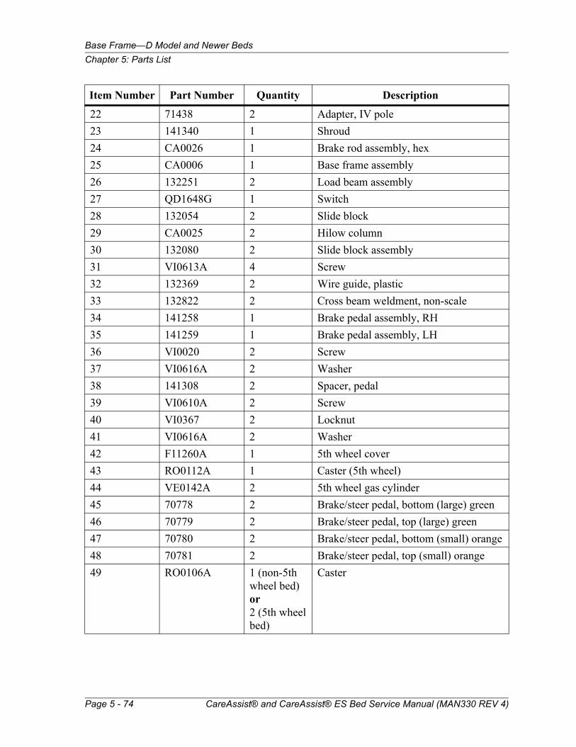
Base Frame—D Model and Newer Beds Chapter 5: Parts List
Item Number Part Number Quantity Description
22 71438 2 Adapter, IV pole 23 141340 1 Shroud 24 CA0026 1 Brake rod assembly, hex 25 CA0006 1 Base frame assembly 26 132251 2 Load beam assembly 27 QD1648G 1 Switch 28 132054 2 Slide block 29 CA0025 2 Hilow column 30 132080 2 Slide block assembly 31 VI0613A 4 Screw 32 132369 2 Wire guide, plastic 33 132822 2 Cross beam weldment, non-scale 34 141258 1 Brake pedal assembly, RH 35 141259 1 Brake pedal assembly, LH 36 VI0020 2 Screw 37 VI0616A 2 Washer 38 141308 2 Spacer, pedal 39 VI0610A 2 Screw 40 VI0367 2 Locknut 41 VI0616A 2 Washer 42 F11260A 1 5th wheel cover 43 RO0112A 1 Caster (5th wheel) 44 VE0142A 2 5th wheel gas cylinder 45 70778 2 Brake/steer pedal, bottom (large) green 46 70779 2 Brake/steer pedal, top (large) green 47 70780 2 Brake/steer pedal, bottom (small) orange 48 70781 2 Brake/steer pedal, top (small) orange 49 RO0106A 1 (non-5th
wheel bed) or 2 (5th wheel bed)
Caster
Page 5 - 74 CareAssist® and CareAssist® ES Bed Service Manual (MAN330 REV 4)

Base Frame—D Model and Newer Beds Chapter 5: Parts List
NOTES:
5
CareAssist® and CareAssist® ES Bed Service Manual (MAN330 REV 4) Page 5 - 75
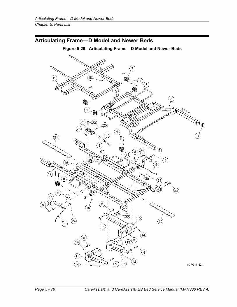
Articulating Frame—D Model and Newer Beds Chapter 5: Parts List
Articulating Frame—D Model and Newer Beds Figure 5-29. Articulating Frame—D Model and Newer Beds
Page 5 - 76 CareAssist® and CareAssist® ES Bed Service Manual (MAN330 REV 4)

Articulating Frame—D Model and Newer Beds Chapter 5: Parts List
Table 5-29. Articulating Frame—D Model and Newer Beds
Item Number Part Number Quantity Description
1 S30531K 4 Bearing 2 154393 1 Thigh and leg weldment 3 QD0589 2 Ear cap 4 VI0609A 8 Screw 5 138036 2 LED assembly (night light) 6 137762 2 Night light housing 7 QD2346 1 Ground strap, thigh frame to intermediate
frame QD2345 1 Ground strap, head frame to intermediate
frame 8 VI0610A 2 Screw 9 S10959A 6 Pin, pivot 10 138884 1 Motor, head section 11 VE0138D 1 Motor, thigh section 12 RM74478A 2 Washer, nylon 13 VE0139C 1 Motor, foot section 14 RM74803A 6 Ring, elastic (E-clip) 15 VI0361 5 Nut 16 QD1545A 4 Stop 17 CAG001 1 Weldment, intermediate frame 18 72274 4 Clip 19 72854 1 Backrest weldment 20 S30555K 1 Cover, short cable tray 21 S30548K 1 Cover, long cable tray 22 71495 2 Weldment, drainage hook 23 VI0609A 2 Screw 24 71991 2 Nut 25 S10850 1 Pivot pin 26 72619 1 Bracket, CPR gas spring mount 27 72494 1 Gas spring 28 RM74804A 1 E-clip 29 VI0616A 4 Washer
5
CareAssist® and CareAssist® ES Bed Service Manual (MAN330 REV 4) Page 5 - 77
Articulating Frame—D Model and Newer Beds Chapter 5: Parts List
Item Number Part Number Quantity Description
30 VI0608 4 Screw 31 138271 1 Alarm, external assembly
Page 5 - 78 CareAssist® and CareAssist® ES Bed Service Manual (MAN330 REV 4)

Articulating Frame—D Model and Newer Beds Chapter 5: Parts List
NOTES:
5
CareAssist® and CareAssist® ES Bed Service Manual (MAN330 REV 4) Page 5 - 79
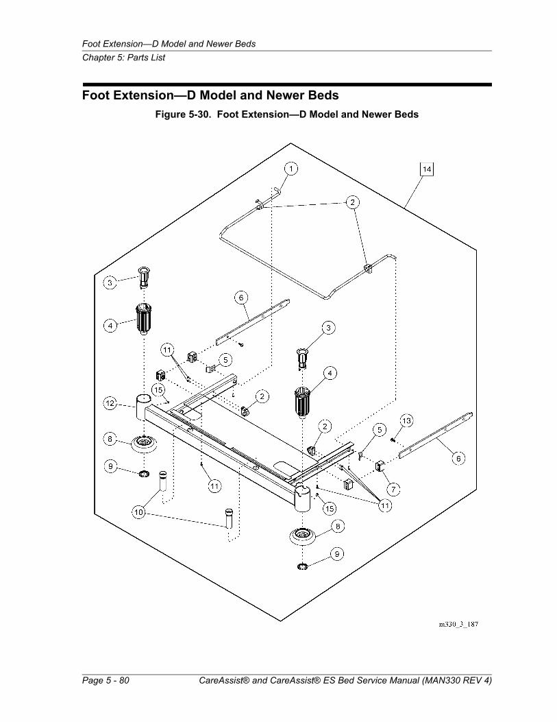
Foot Extension—D Model and Newer Beds Chapter 5: Parts List
Foot Extension—D Model and Newer Beds Figure 5-30. Foot Extension—D Model and Newer Beds
Page 5 - 80 CareAssist® and CareAssist® ES Bed Service Manual (MAN330 REV 4)
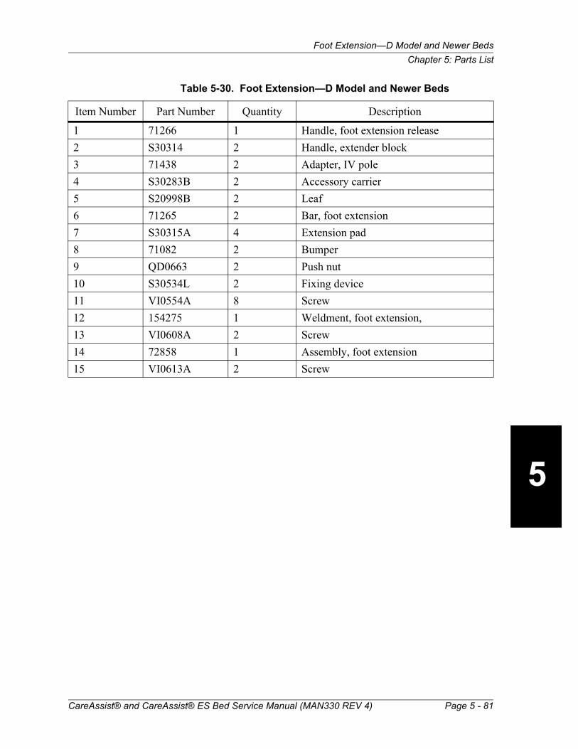
Foot Extension—D Model and Newer Beds Chapter 5: Parts List
Table 5-30. Foot Extension—D Model and Newer Beds
Item Number Part Number Quantity Description
1 71266 1 Handle, foot extension release 2 S30314 2 Handle, extender block 3 71438 2 Adapter, IV pole 4 S30283B 2 Accessory carrier 5 S20998B 2 Leaf 6 71265 2 Bar, foot extension 7 S30315A 4 Extension pad 8 71082 2 Bumper 9 QD0663 2 Push nut 10 S30534L 2 Fixing device 11 VI0554A 8 Screw 12 154275 1 Weldment, foot extension, 13 VI0608A 2 Screw 14 72858 1 Assembly, foot extension 15 VI0613A 2 Screw
5
CareAssist® and CareAssist® ES Bed Service Manual (MAN330 REV 4) Page 5 - 81
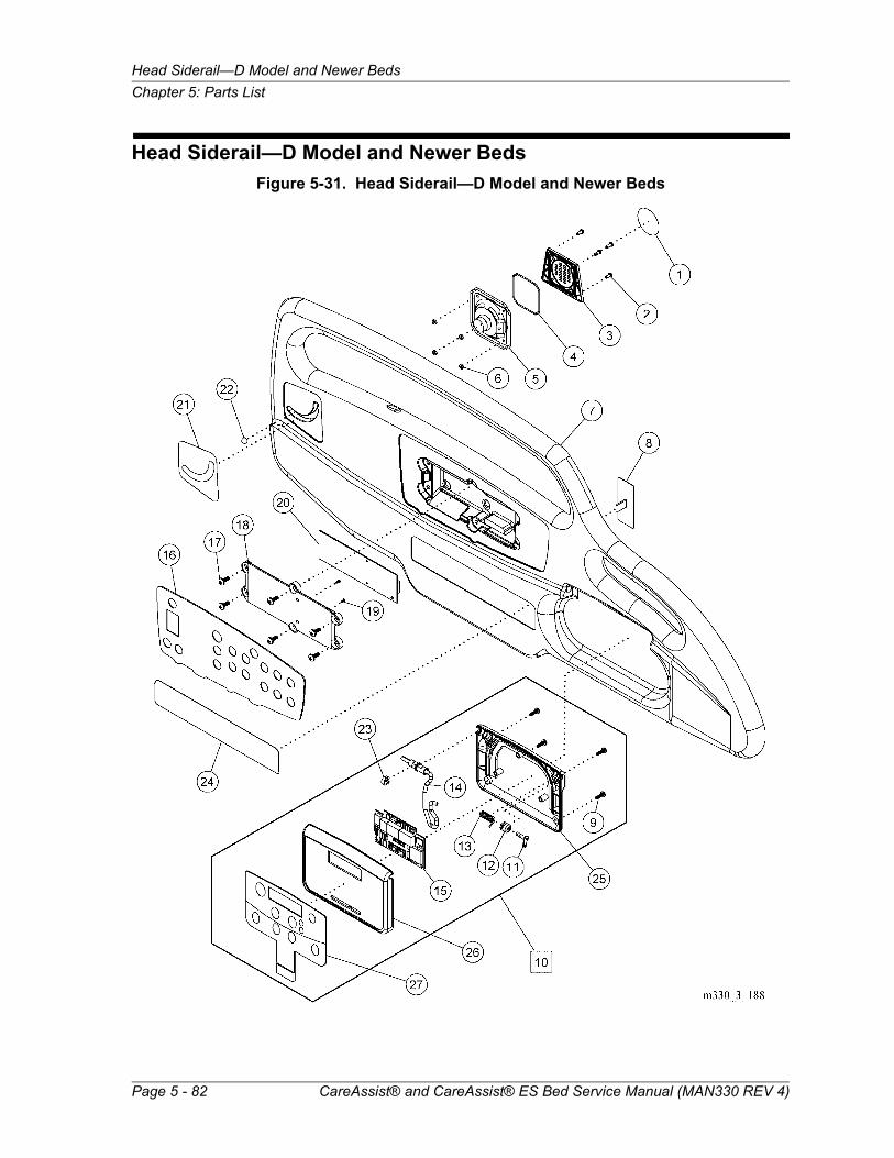
Head Siderail—D Model and Newer Beds Chapter 5: Parts List
Head Siderail—D Model and Newer Beds Figure 5-31. Head Siderail—D Model and Newer Beds
Page 5 - 82 CareAssist® and CareAssist® ES Bed Service Manual (MAN330 REV 4)
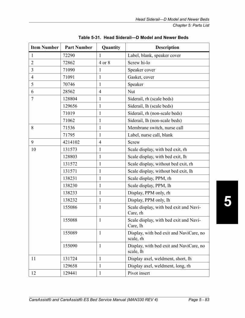
Head Siderail—D Model and Newer Beds Chapter 5: Parts List
Table 5-31. Head Siderail—D Model and Newer Beds
Item Number Part Number Quantity Description
1 72290 1 Label, blank, speaker cover 2 72862 4 or 8 Screw hi-lo 3 71090 1 Speaker cover 4 71091 1 Gasket, cover 5 70746 1 Speaker 6 28562 4 Nut 7 128804 1 Siderail, rh (scale beds)
129656 1 Siderail, lh (scale beds) 71019 1 Siderail, rh (non-scale beds) 71062 1 Siderail, lh (non-scale beds)
8 71536 1 Membrane switch, nurse call 71795 1 Label, nurse call, blank
9 4214102 4 Screw 10 131573 1 Scale display, with bed exit, rh
128803 1 Scale display, with bed exit, lh 131572 1 Scale display, without bed exit, rh 131571 1 Scale display, without bed exit, lh 138231 1 Scale display, PPM, rh 138230 1 Scale display, PPM, lh 138233 1 Display, PPM only, rh 138232 1 Display, PPM only, lh 155086 1 Scale display, with bed exit and Navi-
Care, rh 155088 1 Scale display, with bed exit and Navi-
Care, lh 155089 1 Display, with bed exit and NaviCare, no
scale, rh 155090 1 Display, with bed exit and NaviCare, no
scale, lh 11 131724 1 Display axel, weldment, short, lh
129658 1 Display axel, weldment, long, rh 12 129441 1 Pivot insert
5
CareAssist® and CareAssist® ES Bed Service Manual (MAN330 REV 4) Page 5 - 83
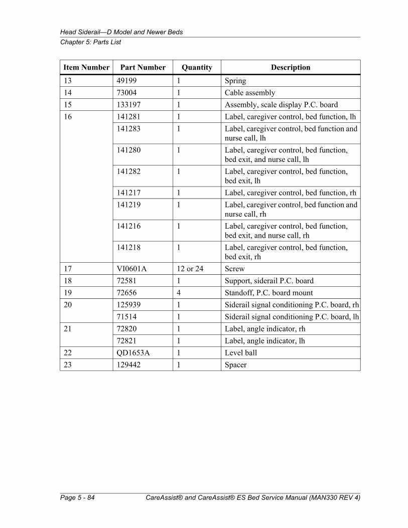
Head Siderail—D Model and Newer Beds Chapter 5: Parts List
Item Number Part Number Quantity Description
13 49199 1 Spring 14 73004 1 Cable assembly 15 133197 1 Assembly, scale display P.C. board 16 141281 1 Label, caregiver control, bed function, lh
141283 1 Label, caregiver control, bed function and nurse call, lh
141280 1 Label, caregiver control, bed function, bed exit, and nurse call, lh
141282 1 Label, caregiver control, bed function, bed exit, lh
141217 1 Label, caregiver control, bed function, rh 141219 1 Label, caregiver control, bed function and
nurse call, rh 141216 1 Label, caregiver control, bed function,
bed exit, and nurse call, rh 141218 1 Label, caregiver control, bed function,
bed exit, rh 17 VI0601A 12 or 24 Screw 18 72581 1 Support, siderail P.C. board 19 72656 4 Standoff, P.C. board mount 20 125939 1 Siderail signal conditioning P.C. board, rh
71514 1 Siderail signal conditioning P.C. board, lh 21 72820 1 Label, angle indicator, rh
72821 1 Label, angle indicator, lh 22 QD1653A 1 Level ball 23 129442 1 Spacer
Page 5 - 84 CareAssist® and CareAssist® ES Bed Service Manual (MAN330 REV 4)
Head Siderail—D Model and Newer Beds Chapter 5: Parts List
Item Number Part Number Quantity Description
24 131857 1 Label, scale (English) 133011 1 Label, scale (Japanese) 133012 1 Label, scale (Simplified Chinese) 133013 1 Label, scale (French) 133015 1 Label, scale (Traditional Chinese) 133016 1 Label, scale (Thai) 133017 1 Label, scale (Korean) 133018 1 Label, scale (Portuguese) 133019 1 Label, scale (Spanish)
25 128806 1 Scale display housing, back 26 128805 1 Scale display housing, front 27 128749 1 Scale display membrane
5
CareAssist® and CareAssist® ES Bed Service Manual (MAN330 REV 4) Page 5 - 85
Head Siderail Mounting—D Model and Newer Beds Chapter 5: Parts List
Head Siderail Mounting—D Model and Newer Beds Figure 5-32. Head Siderail Mounting—D Model and Newer Beds
Page 5 - 86 CareAssist® and CareAssist® ES Bed Service Manual (MAN330 REV 4)

Head Siderail Mounting—D Model and Newer Beds Chapter 5: Parts List
Table 5-32. Head Siderail Mounting—D Model and Newer Beds
Item Number Part Number Quantity Description
1 CA0007 1 Siderail mount assembly, head 2 71372 1 Siderail cable 3 S40029A 2 Siderail arm, painted 4 S10951B 1 Pivot pin, outer arm, upper 5 S10956B 2 Pivot pin, outer, lower 6 RM74478A 2 Washer, nylon 7 RM74803A 6 E-clip 8 72862 3 Screw 9 151632 1 Cover, siderail center arm 10 S10952B 1 Pivot pin, center arm, upper 11 71086 1 Enclosure, center arm 12 71085 1 Handle, siderail 13 S20950F 1 Siderail mount, painted 14 71436 1 Cover, head 15 155007 1 Head siderail mounting bracket, painted 16 72991 2 Assembly, spring guide, head 17 72791 1 Spring, siderail dampening, head 18 71654 1 Siderail center arm assembly, painted 19 S10953B 1 Pivot pin, center arm, lower 20 VI0601A 6 Screw 21 151315 1 Siderail reed switch assembly, F model
beds 22 6561406 2 Screw
5
CareAssist® and CareAssist® ES Bed Service Manual (MAN330 REV 4) Page 5 - 87
Foot Siderail—D Model and Newer Beds Chapter 5: Parts List
Foot Siderail—D Model and Newer Beds Figure 5-33. Foot Siderail—D Model and Newer Beds
Page 5 - 88 CareAssist® and CareAssist® ES Bed Service Manual (MAN330 REV 4)

Foot Siderail—D Model and Newer Beds Chapter 5: Parts List
Table 5-33. Foot Siderail—D Model and Newer Beds
Item Number Part Number Quantity Description
1 S10953B 1 Pivot pin, center arm, lower 2 155008 1 Weldment, foot siderail mounting bracket 3 RM74803A 6 E-clip 4 72990 2 Spring guide, assembly 5 72862 3 Screw, hilow 6 151632 1 Cover, center arm 7 S10952B 1 Pivot pin, center arm, upper 8 71654 1 Weldment, center arm assembly 9 S10951B 1 Pivot pin, outer arm, upper 10 S10956B 2 Pivot pin 11 71086 1 Enclosure, center arm 12 71085 1 Handle, siderail 13 S40029A 2 Siderail arm, painted 14 RM74478A 2 Washer, nylon 15 CA0008 1 Foot siderail mechanism 16 VI0601A 6 Screw 17 S20950F 1 Siderail mount, painted 18 71436 1 Cover, head 19 71018 1 Siderail assembly, foot end, rh
71061 1 Siderail assembly, foot end, lh 20 71656 1 Label 21 QD1653A 1 Level ball 22 72792 1 Spring, siderail, foot 23 151315 1 Siderail reed switch assembly, F model
beds 24 6561406 2 Screw
5
CareAssist® and CareAssist® ES Bed Service Manual (MAN330 REV 4) Page 5 - 89
Footboard and Headboard—D Model and Newer Beds Chapter 5: Parts List
Footboard and Headboard—D Model and Newer Beds Figure 5-34. Footboard and Headboard—D Model and Newer Beds
Table 5-34. Footboard and Headboard—D Model and Newer Beds
Item Number Part Number Quantity Description
1 71650 1 Label 2 141203 1 HILL-ROM Label 3 141201 1 Footboard or headboard assembly 4 71549 1 CPR label
Page 5 - 90 CareAssist® and CareAssist® ES Bed Service Manual (MAN330 REV 4)
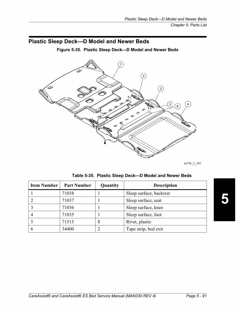
Plastic Sleep Deck—D Model and Newer Beds Chapter 5: Parts List
Plastic Sleep Deck—D Model and Newer Beds Figure 5-35. Plastic Sleep Deck—D Model and Newer Beds
Table 5-35. Plastic Sleep Deck—D Model and Newer Beds
Item Number Part Number Quantity Description
1 71038 1 Sleep surface, backrest 2 71037 1 Sleep surface, seat 3 71036 1 Sleep surface, knee 4 71035 1 Sleep surface, foot 5 71515 8 Rivet, plastic 6 34400 2 Tape strip, bed exit
5
CareAssist® and CareAssist® ES Bed Service Manual (MAN330 REV 4) Page 5 - 91
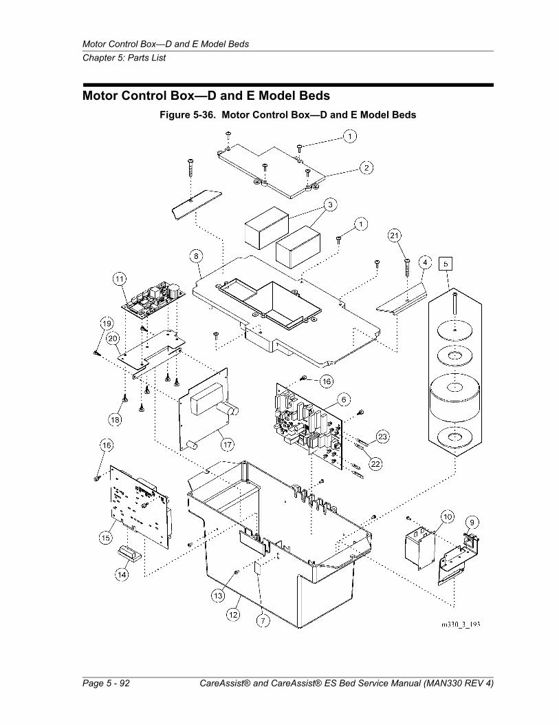
Motor Control Box—D and E Model Beds Chapter 5: Parts List
Motor Control Box—D and E Model Beds Figure 5-36. Motor Control Box—D and E Model Beds
Page 5 - 92 CareAssist® and CareAssist® ES Bed Service Manual (MAN330 REV 4)

Motor Control Box—D and E Model Beds Chapter 5: Parts List
Table 5-36. Motor Control Box—D and E Model Beds
Item Number Part Number Quantity Description
1 VI0601A 7 Screw 2 132547 1 Cover assembly, battery compartment 3 QD1642A 2 Battery, 12 V 4 132219 2 Washer 5 128816 1 Transformer, North America
128829 1 Transformer, International 6 137613 1 Assembly, siderail interface P.C. board 7 127865 1 Label, blank 8 132546 1 Cover 9 132094 1 Power cord mount 10 70611 1 Line filter 11 150139 1 P.C. board assy, scale and PPM, 400 lb (D
model bed) 150140 1 P.C. board assy, PPM only, 400 lb
(D model bed) 150141 1 P.C. board assy, scale only, 400 lb
(D model bed) 148822 1 P.C. board assy, scale and PPM, 500 lb
(E model bed) 148823 1 P.C. board assy, PPM only, 500 lb
(E model bed) 148824 1 P.C. board assy, scale only, 500 lb
(E model bed) 12 130628 1 Electrical enclosure 13 VI0395 4 Screw 14 4476703 1 UTV adapter, Zenith 92
4476701 1 UTV adapter, standard analog 15 129741 1 Assembly, SideCom® Communication
System P.C. board 16 132934 5 Circuit board support (standoff) 17 132628 1 P.C. board, motor control 18 3976301 5 Standoff 19 132935 2 Circuit board support (standoff)
5
CareAssist® and CareAssist® ES Bed Service Manual (MAN330 REV 4) Page 5 - 93
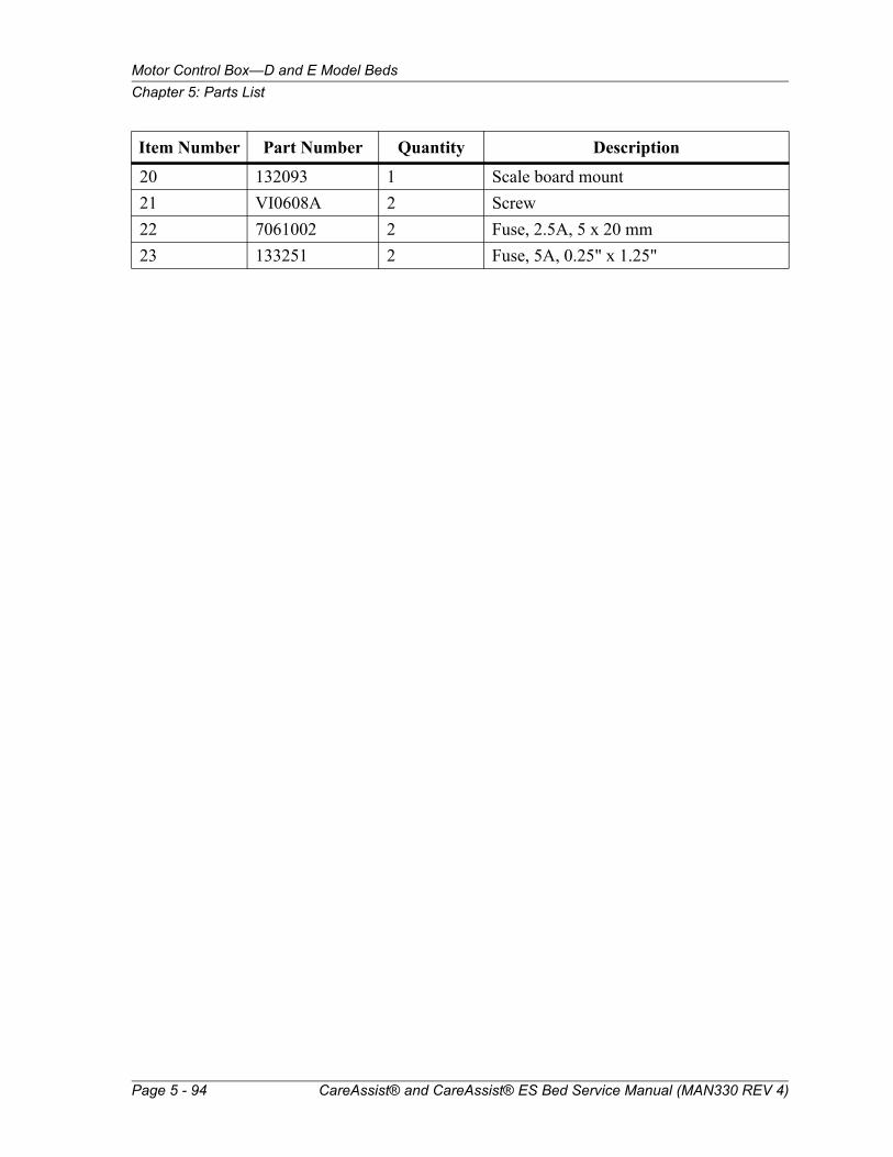
Motor Control Box—D and E Model Beds Chapter 5: Parts List
Item Number Part Number Quantity Description
20 132093 1 Scale board mount 21 VI0608A 2 Screw 22 7061002 2 Fuse, 2.5A, 5 x 20 mm 23 133251 2 Fuse, 5A, 0.25" x 1.25"
Page 5 - 94 CareAssist® and CareAssist® ES Bed Service Manual (MAN330 REV 4)
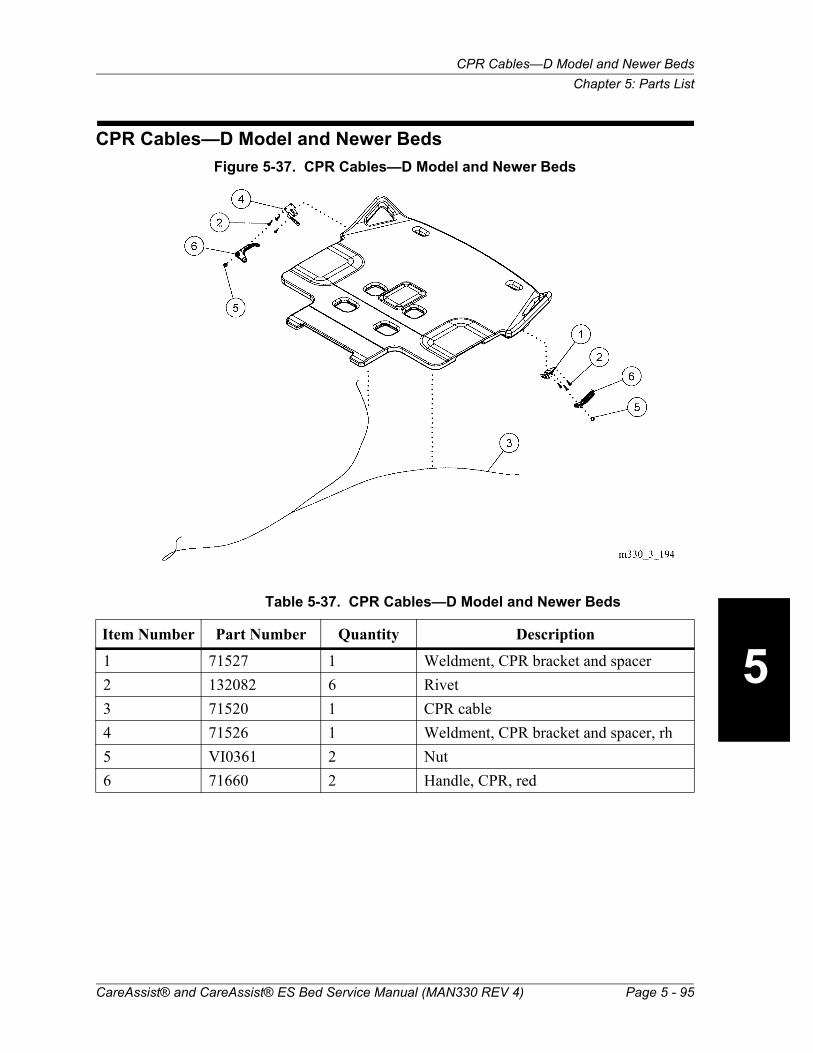
CPR Cables—D Model and Newer Beds Chapter 5: Parts List
CPR Cables—D Model and Newer Beds Figure 5-37. CPR Cables—D Model and Newer Beds
Table 5-37. CPR Cables—D Model and Newer Beds
Item Number Part Number Quantity Description
1 71527 1 Weldment, CPR bracket and spacer 2 132082 6 Rivet 3 71520 1 CPR cable 4 71526 1 Weldment, CPR bracket and spacer, rh 5 VI0361 2 Nut 6 71660 2 Handle, CPR, red
5
CareAssist® and CareAssist® ES Bed Service Manual (MAN330 REV 4) Page 5 - 95
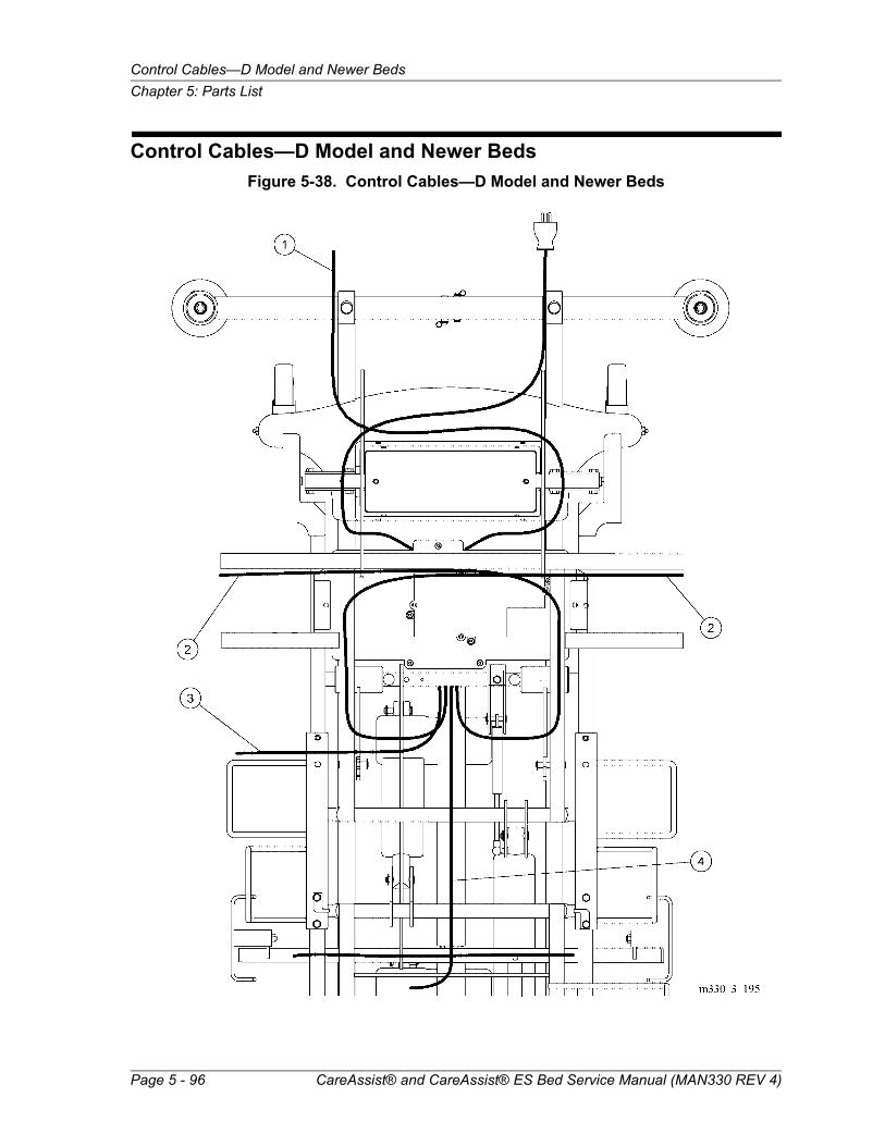
Control Cables—D Model and Newer Beds Chapter 5: Parts List
Control Cables—D Model and Newer Beds Figure 5-38. Control Cables—D Model and Newer Beds
Page 5 - 96 CareAssist® and CareAssist® ES Bed Service Manual (MAN330 REV 4)
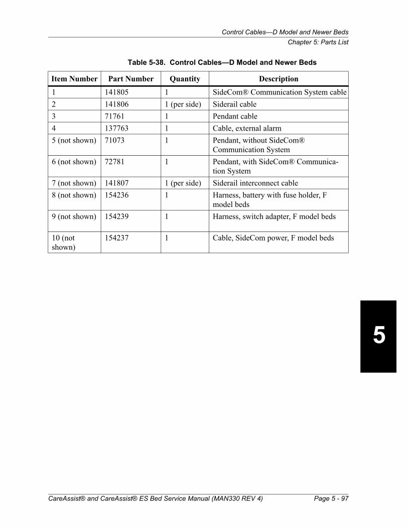
Control Cables—D Model and Newer Beds Chapter 5: Parts List
Table 5-38. Control Cables—D Model and Newer Beds
Item Number Part Number Quantity Description
1 141805 1 SideCom® Communication System cable 2 141806 1 (per side) Siderail cable 3 71761 1 Pendant cable 4 137763 1 Cable, external alarm 5 (not shown) 71073 1 Pendant, without SideCom®
Communication System 6 (not shown) 72781 1 Pendant, with SideCom® Communica
tion System 7 (not shown) 141807 1 (per side) Siderail interconnect cable 8 (not shown) 154236 1 Harness, battery with fuse holder, F
model beds 9 (not shown) 154239 1 Harness, switch adapter, F model beds
10 (not shown)
154237 1 Cable, SideCom power, F model beds
5
CareAssist® and CareAssist® ES Bed Service Manual (MAN330 REV 4) Page 5 - 97
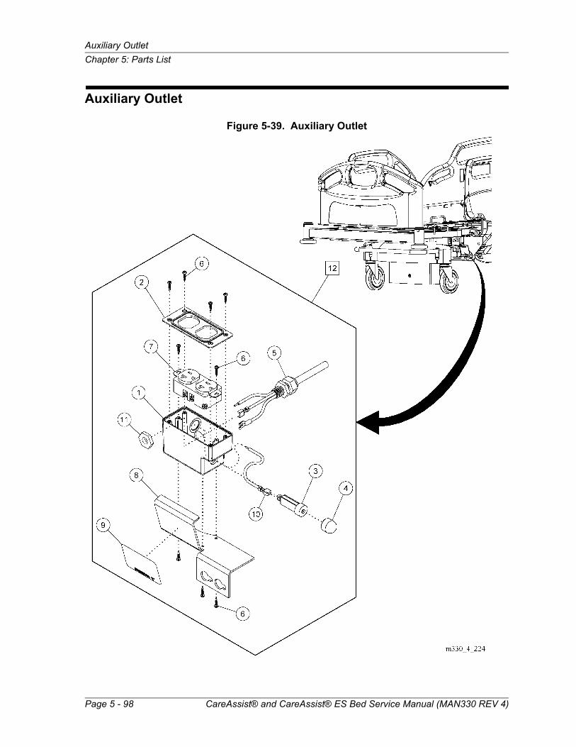
Auxiliary Outlet Chapter 5: Parts List
Auxiliary Outlet
Figure 5-39. Auxiliary Outlet
Page 5 - 98 CareAssist® and CareAssist® ES Bed Service Manual (MAN330 REV 4)
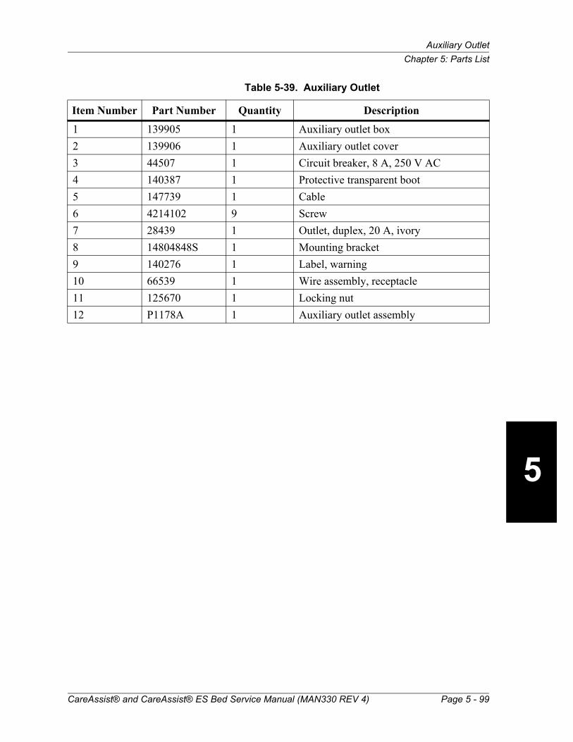
Auxiliary Outlet Chapter 5: Parts List
Table 5-39. Auxiliary Outlet
Item Number Part Number Quantity Description
1 139905 1 Auxiliary outlet box 2 139906 1 Auxiliary outlet cover 3 44507 1 Circuit breaker, 8 A, 250 V AC 4 140387 1 Protective transparent boot 5 147739 1 Cable 6 4214102 9 Screw 7 28439 1 Outlet, duplex, 20 A, ivory 8 14804848S 1 Mounting bracket 9 140276 1 Label, warning 10 66539 1 Wire assembly, receptacle 11 125670 1 Locking nut 12 P1178A 1 Auxiliary outlet assembly
5
CareAssist® and CareAssist® ES Bed Service Manual (MAN330 REV 4) Page 5 - 99

SafeView™ Alerts Chapter 5: Parts List
SafeView™ Alerts Figure 5-40. SafeView™ Alerts
Table 5-40. SafeView™ Alerts
Item Number Part Number Quantity Description
1 42142 4 Screw 2 15677202 1 Bracket, rh
15677201 1 Bracket, lh 3 154238 2 Light assembly
Page 5 - 100 CareAssist® and CareAssist® ES Bed Service Manual (MAN330 REV 4)

SafeView™ Alerts Chapter 5: Parts List
NOTES:
5
CareAssist® and CareAssist® ES Bed Service Manual (MAN330 REV 4) Page 5 - 101
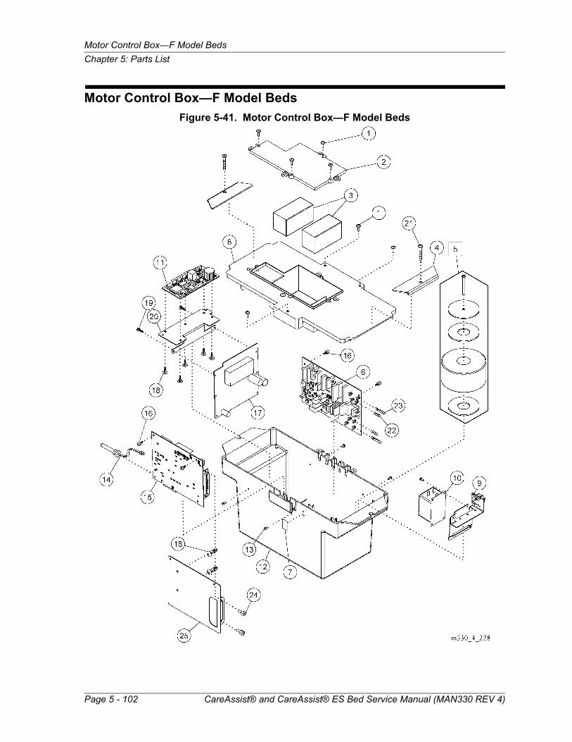
Motor Control Box—F Model Beds Chapter 5: Parts List
Motor Control Box—F Model Beds Figure 5-41. Motor Control Box—F Model Beds
Page 5 - 102 CareAssist® and CareAssist® ES Bed Service Manual (MAN330 REV 4)
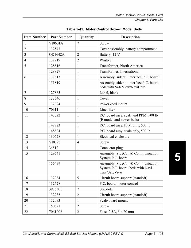
Motor Control Box—F Model Beds Chapter 5: Parts List
Table 5-41. Motor Control Box—F Model Beds
Item Number Part Number Quantity Description
1 VI0601A 7 Screw 2 132547 1 Cover assembly, battery compartment 3 QD1642A 2 Battery, 12 V 4 132219 2 Washer 5 128816 1 Transformer, North America
128829 1 Transformer, International 6 137613 1 Assembly, siderail interface P.C. board
151819 1 Assembly, siderail interface P.C. board, beds with SafeView/NaviCare
7 127865 1 Label, blank 8 132546 1 Cover 9 132094 1 Power cord mount 10 70611 1 Line filter 11 148822 1 P.C. board assy, scale and PPM, 500 lb
(E model and newer beds) 148823 1 P.C. board assy, PPM only, 500 lb 148824 1 P.C. board assy, scale only, 500 lb
12 130628 1 Electrical enclosure 13 VI0395 4 Screw 14 34512 1 Connector plug 15 129741 1 Assembly, SideCom® Communication
System P.C. board 156499 1 Assembly, SideCom® Communication
System P.C. board, beds with Navi-Care/SafeView
16 132934 5 Circuit board support (standoff) 17 132628 1 P.C. board, motor control 18 3976301 7 Standoff 19 132935 2 Circuit board support (standoff) 20 132093 1 Scale board mount 21 150621 2 Screw 22 7061002 2 Fuse, 2.5A, 5 x 20 mm
5
CareAssist® and CareAssist® ES Bed Service Manual (MAN330 REV 4) Page 5 - 103
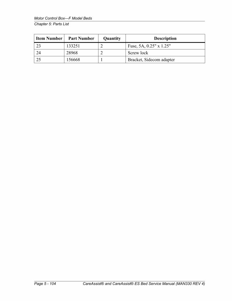
Motor Control Box—F Model Beds Chapter 5: Parts List
Item Number Part Number Quantity Description
23 133251 2 Fuse, 5A, 0.25" x 1.25" 24 28968 2 Screw lock 25 156668 1 Bracket, Sidecom adapter
Page 5 - 104 CareAssist® and CareAssist® ES Bed Service Manual (MAN330 REV 4)
Chapter 6 General Procedures
Clean and Disinfect
We recommend that you clean and disinfect the CareAssist® Bed between patient use and regularly during extended patient stays. Refer to your facility’s cleaning and disinfection policies, and follow the guidelines below.
SHOCK HAZARD: Follow the product manufacturer’s instructions. Failure to do so could cause personal injury or equipment damage.
SHOCK HAZARD: The potential for electrical shock exists with electrical equipment. Failure to follow facility protocol could cause death or serious injury.
SHOCK HAZARD: Failure to unplug the bed from its power source before you clean or disinfect the bed could cause personal injury or equipment damage.
SHOCK HAZARD: Do not expose the unit to excessive moisture. Personal injury or equipment damage could occur.
CAUTION: Do not steam clean or power wash the bed or mattress. Pressure and excessive moisture can damage the mattress and the protective surfaces of the bed and its electrical components. 6
CareAssist® and CareAssist® ES Bed Service Manual (MAN330 REV 4) Page 6 - 1
Clean and Disinfect Chapter 6: General Procedures
CAUTION: Do not use harsh cleaners, solvents, or detergents. Equipment damage could occur.
CAUTION: Make sure the bed frame is dry before you put the mattress on the bed. Failure to do so could cause equipment damage.
NOTE: Clean and disinfect surfaces with nano Ag+™ Technology as you would other surfaces. This product is not intended to protect users or others against bacteria, viruses, germs, or other disease organisms. Always disinfect Hill-Rom surfaces throroughly after each use according to facility protocol. Refer to “Clean” and Disinfect” below.
Clean
1. Unplug the bed.
2. Remove all linens.
3. Use these to clean the bed:
• A soft cloth soaked with warm water and a facility-approved general cleaning soap/detergent solution. Make sure the cloth is not so wet as to cause the cleaning solution to pool or flood on the mattress or other bed components.
• A soft brush to remove stains and resistant soil. Do not use harsh or abrasive cleansers, solvents, or scouring pads.
Page 6 - 2 CareAssist® and CareAssist® ES Bed Service Manual (MAN330 REV 4)
Clean and Disinfect Chapter 6: General Procedures
4. Clean the bed. Give special attention to these areas:
• Headboard—thoroughly clean as this is a high-touch area
• Footboard
• Siderails—thoroughly clean the high-touch areas such as the upper and under sides of the siderail releases, pendants, and patient controls
• Bed frame
• Casters
• All other bed components
• Fully-extended IV pole
• Bed accessories that can be used again such as the mattress and patient helper
NOTE: If you turn the mattress to clean it, make sure the cleaning solution does not pool or flow on to the other side or edges of the mattress. This may permit fluid to get into the mattress air outlets and zipper closures that ordinarily are protected by the ticking flaps.
5. Examine the condition of the mattress. If there are holes, tears, or other signs of damage or deterioration of the ticking, replace the mattress.
6. Disinfect the bed as described below.
Disinfect
Wipe down all surfaces with a facility-approved disinfectant, used in accordance with the manufacturer's instructions. Give special attention to high-touch areas such as the siderails, upper and under sides of siderail releases, pendants, patient controls, and headboards.
6
CareAssist® and CareAssist® ES Bed Service Manual (MAN330 REV 4) Page 6 - 3
Component Handling Chapter 6: General Procedures
Component Handling
CAUTION: To help prevent component damage, make sure your hands are clean, and only handle the P.C. board by its edges.
CAUTION: When handling electronic components, wear an antistatic strap. Failure to do so could cause component damage.
CAUTION: For shipping and storage, place the removed P.C. board in an antistatic protective bag. Equipment damage can occur.
P.C. Board
When servicing the P.C. board, follow good handling practices. Mishandling a P.C. board can cause the following:
• P.C. board damage
• Shortened P.C. board life
• Unit malfunctions
Observe the following P.C. board handling rules:
• Make sure your hands are clean and free of moisture, oily liquids, etc.
• Only handle the P.C. board by its outer edges.
• Do not touch the P.C. board components. Finger contact with the board surface and/or with its components can leave a deposit that will result in board (and component) deterioration.
• When working with electronics, wear an appropriate antistatic strap, and make sure it is properly grounded.
• Service the removed P.C. board at a static-free workstation that is properly grounded.
• For shipping and storage, place the removed P.C. board in an antistatic protective bag.
Page 6 - 4 CareAssist® and CareAssist® ES Bed Service Manual (MAN330 REV 4)
Lubrication Requirements Chapter 6: General Procedures
Lubrication Requirements
There are no lubrication requirements for the CareAssist® and CareAssist® ES Bed.
6
CareAssist® and CareAssist® ES Bed Service Manual (MAN330 REV 4) Page 6 - 5
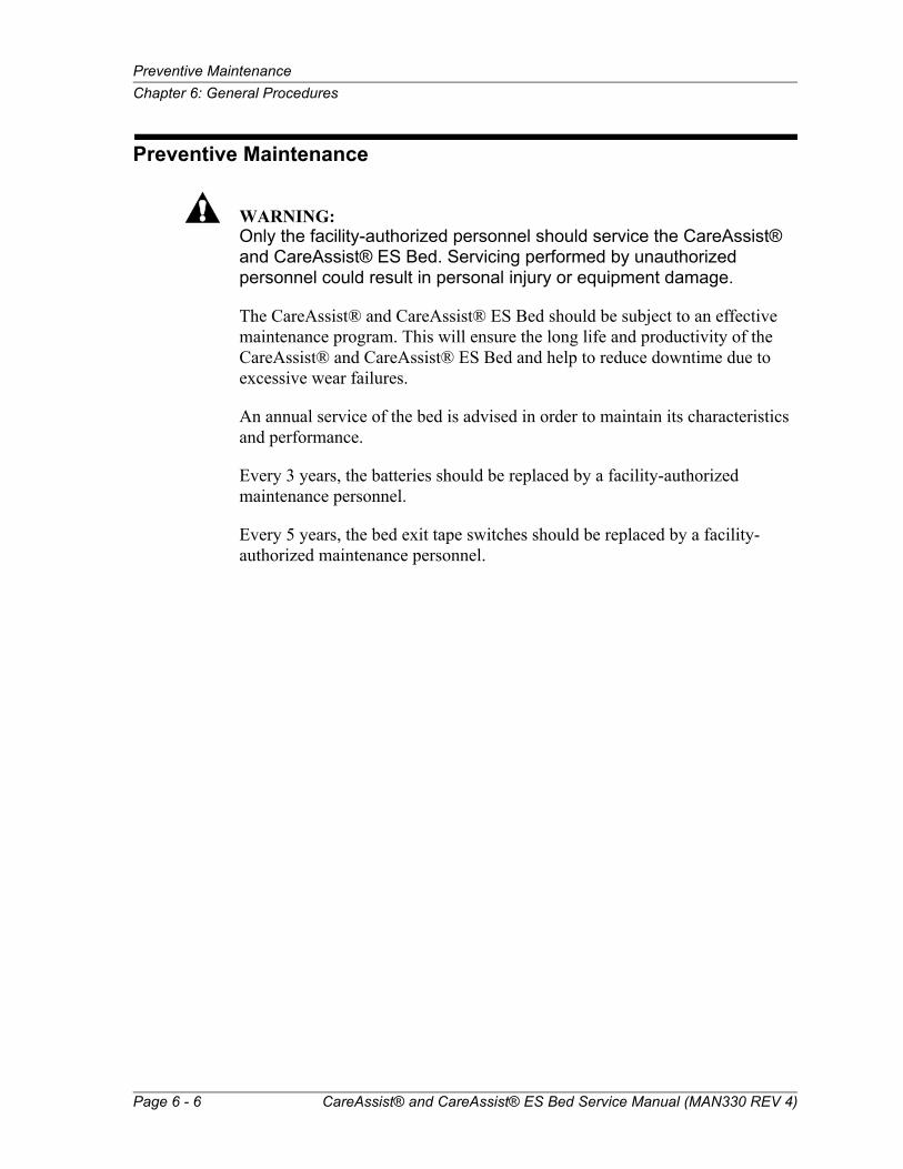
Preventive Maintenance Chapter 6: General Procedures
Preventive Maintenance
WARNING: Only the facility-authorized personnel should service the CareAssist® and CareAssist® ES Bed. Servicing performed by unauthorized personnel could result in personal injury or equipment damage.
The CareAssist® and CareAssist® ES Bed should be subject to an effective maintenance program. This will ensure the long life and productivity of the CareAssist® and CareAssist® ES Bed and help to reduce downtime due to excessive wear failures.
An annual service of the bed is advised in order to maintain its characteristics and performance.
Every 3 years, the batteries should be replaced by a facility-authorized maintenance personnel.
Every 5 years, the bed exit tape switches should be replaced by a facility-authorized maintenance personnel.
Page 6 - 6 CareAssist® and CareAssist® ES Bed Service Manual (MAN330 REV 4)
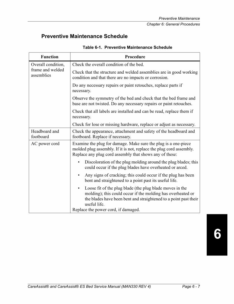
Preventive Maintenance Chapter 6: General Procedures
Preventive Maintenance Schedule
Table 6-1. Preventive Maintenance Schedule
Function Procedure
Overall condition, Check the overall condition of the bed. frame and welded assemblies
Check that the structure and welded assemblies are in good working condition and that there are no impacts or corrosion.
Do any necessary repairs or paint retouches, replace parts if necessary.
Observe the symmetry of the bed and check that the bed frame and base are not twisted. Do any necessary repairs or paint retouches.
Check that all labels are installed and can be read, replace them if necessary.
Check for lose or missing hardware, replace or adjust as necessary. Headboard and footboard
Check the appearance, attachment and safety of the headboard and footboard. Replace if necessary.
AC power cord Examine the plug for damage. Make sure the plug is a one-piece molded plug assembly. If it is not, replace the plug cord assembly. Replace any plug cord assembly that shows any of these:
• Discoloration of the plug molding around the plug blades; this could occur if the plug blades have overheated or arced.
• Any signs of cracking; this could occur if the plug has been bent and straightened to a point past its useful life.
• Loose fit of the plug blade (the plug blade moves in the molding); this could occur if the molding has overheated or the blades have been bent and straightened to a point past their useful life.
Replace the power cord, if damaged.
6
CareAssist® and CareAssist® ES Bed Service Manual (MAN330 REV 4) Page 6 - 7
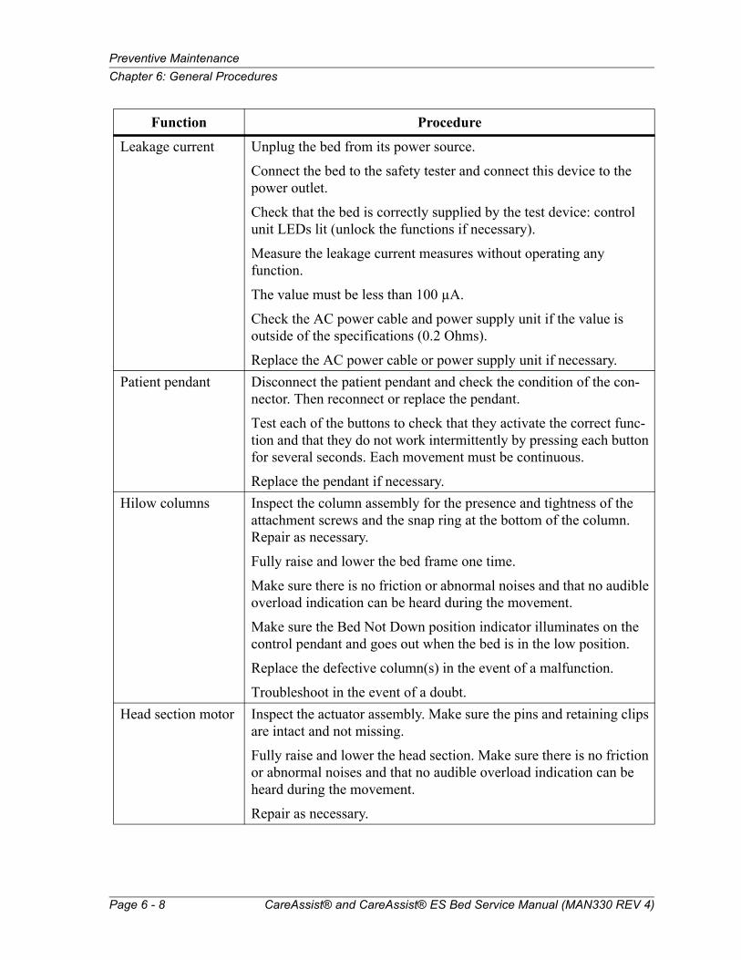
Preventive Maintenance Chapter 6: General Procedures
Function Procedure
Leakage current Unplug the bed from its power source.
Connect the bed to the safety tester and connect this device to the power outlet.
Check that the bed is correctly supplied by the test device: control unit LEDs lit (unlock the functions if necessary).
Measure the leakage current measures without operating any function.
The value must be less than 100 µA.
Check the AC power cable and power supply unit if the value is outside of the specifications (0.2 Ohms).
Replace the AC power cable or power supply unit if necessary. Patient pendant Disconnect the patient pendant and check the condition of the con
nector. Then reconnect or replace the pendant.
Test each of the buttons to check that they activate the correct function and that they do not work intermittently by pressing each button for several seconds. Each movement must be continuous.
Replace the pendant if necessary. Hilow columns Inspect the column assembly for the presence and tightness of the
attachment screws and the snap ring at the bottom of the column. Repair as necessary.
Fully raise and lower the bed frame one time.
Make sure there is no friction or abnormal noises and that no audible overload indication can be heard during the movement.
Make sure the Bed Not Down position indicator illuminates on the control pendant and goes out when the bed is in the low position.
Replace the defective column(s) in the event of a malfunction.
Troubleshoot in the event of a doubt. Head section motor Inspect the actuator assembly. Make sure the pins and retaining clips
are intact and not missing.
Fully raise and lower the head section. Make sure there is no friction or abnormal noises and that no audible overload indication can be heard during the movement.
Repair as necessary.
Page 6 - 8 CareAssist® and CareAssist® ES Bed Service Manual (MAN330 REV 4)
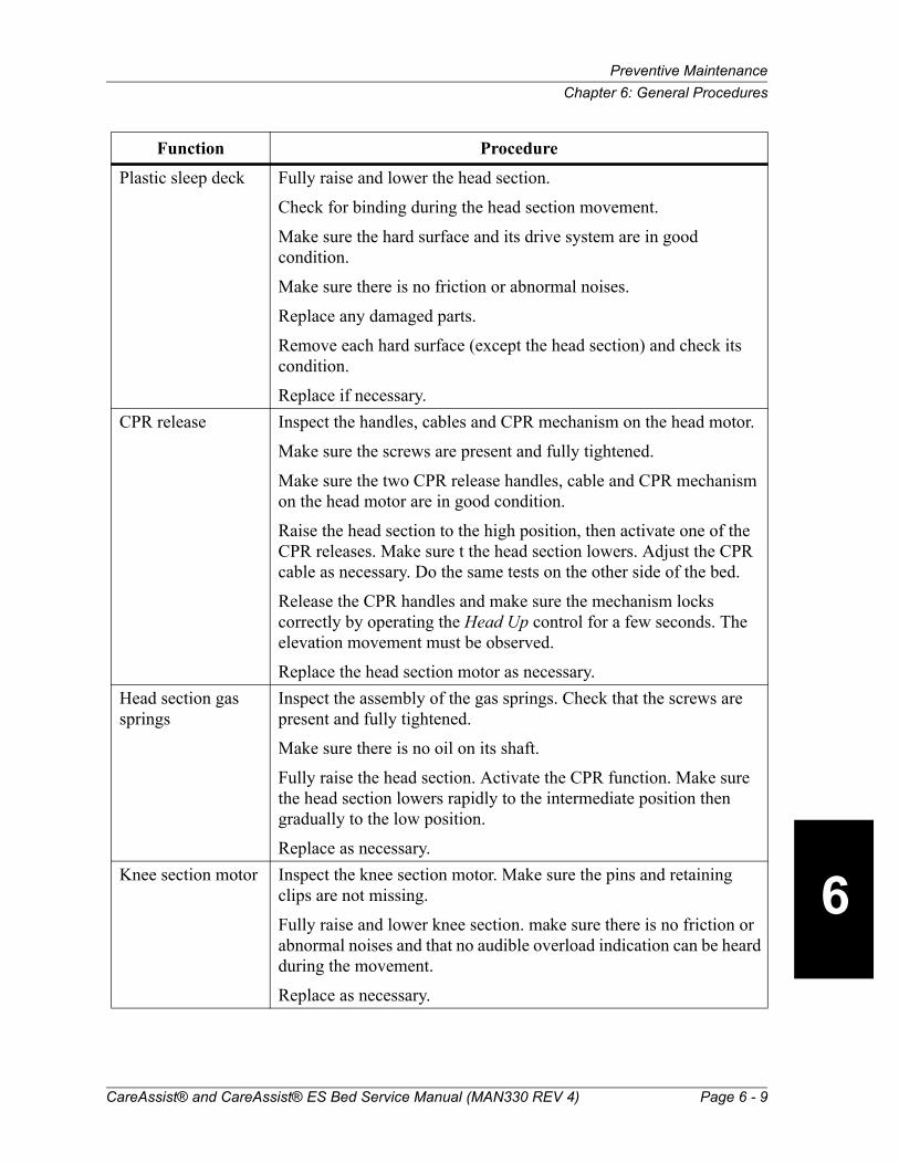
Preventive Maintenance Chapter 6: General Procedures
Function Procedure
Plastic sleep deck Fully raise and lower the head section.
Check for binding during the head section movement.
Make sure the hard surface and its drive system are in good condition.
Make sure there is no friction or abnormal noises.
Replace any damaged parts.
Remove each hard surface (except the head section) and check its condition.
Replace if necessary. CPR release Inspect the handles, cables and CPR mechanism on the head motor.
Make sure the screws are present and fully tightened.
Make sure the two CPR release handles, cable and CPR mechanism on the head motor are in good condition.
Raise the head section to the high position, then activate one of the CPR releases. Make sure t the head section lowers. Adjust the CPR cable as necessary. Do the same tests on the other side of the bed.
Release the CPR handles and make sure the mechanism locks correctly by operating the Head Up control for a few seconds. The elevation movement must be observed.
Replace the head section motor as necessary. Head section gas Inspect the assembly of the gas springs. Check that the screws are springs present and fully tightened.
Make sure there is no oil on its shaft.
Fully raise the head section. Activate the CPR function. Make sure the head section lowers rapidly to the intermediate position then gradually to the low position.
Replace as necessary. Knee section motor Inspect the knee section motor. Make sure the pins and retaining
clips are not missing.
Fully raise and lower knee section. make sure there is no friction or abnormal noises and that no audible overload indication can be heard during the movement.
Replace as necessary.
6
CareAssist® and CareAssist® ES Bed Service Manual (MAN330 REV 4) Page 6 - 9
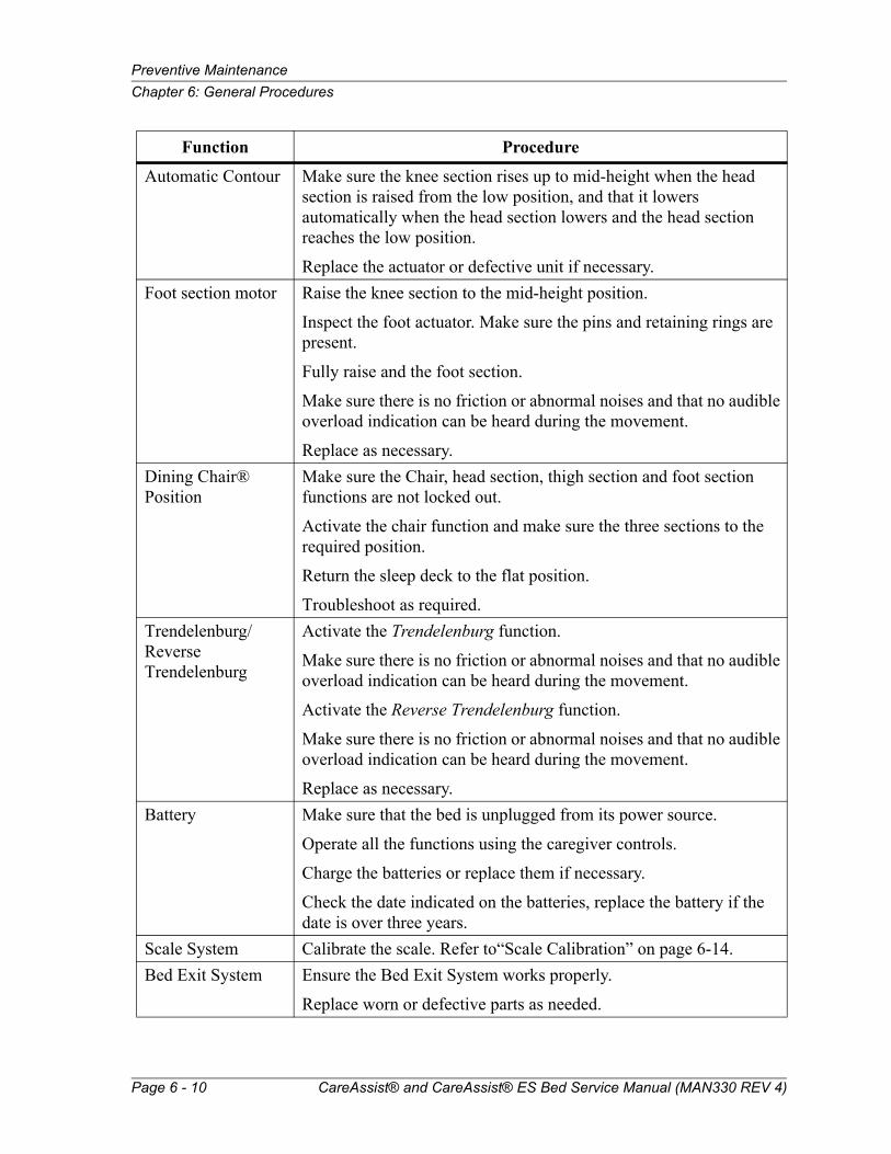
Preventive Maintenance Chapter 6: General Procedures
Function Procedure
Automatic Contour Make sure the knee section rises up to mid-height when the head section is raised from the low position, and that it lowers automatically when the head section lowers and the head section reaches the low position.
Replace the actuator or defective unit if necessary. Foot section motor Raise the knee section to the mid-height position.
Inspect the foot actuator. Make sure the pins and retaining rings are present.
Fully raise and the foot section.
Make sure there is no friction or abnormal noises and that no audible overload indication can be heard during the movement.
Replace as necessary. Dining Chair® Position
Make sure the Chair, head section, thigh section and foot section functions are not locked out.
Activate the chair function and make sure the three sections to the required position.
Return the sleep deck to the flat position.
Troubleshoot as required. Trendelenburg/ Reverse Trendelenburg
Activate the Trendelenburg function.
Make sure there is no friction or abnormal noises and that no audible overload indication can be heard during the movement.
Activate the Reverse Trendelenburg function.
Make sure there is no friction or abnormal noises and that no audible overload indication can be heard during the movement.
Replace as necessary. Battery Make sure that the bed is unplugged from its power source.
Operate all the functions using the caregiver controls.
Charge the batteries or replace them if necessary.
Check the date indicated on the batteries, replace the battery if the date is over three years.
Scale System Calibrate the scale. Refer to“Scale Calibration” on page 6-14. Bed Exit System Ensure the Bed Exit System works properly.
Replace worn or defective parts as needed.
Page 6 - 10 CareAssist® and CareAssist® ES Bed Service Manual (MAN330 REV 4)
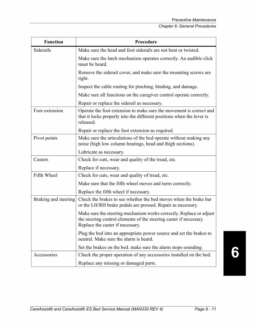
Preventive Maintenance Chapter 6: General Procedures
Function Procedure
Siderails Make sure the head and foot siderails are not bent or twisted.
Make sure the latch mechanism operates correctly. An audible click must be heard.
Remove the siderail cover, and make sure the mounting screws are tight.
Inspect the cable routing for pinching, binding, and damage.
Make sure all functions on the caregiver control operate correctly.
Repair or replace the siderail as necessary. Foot extension Operate the foot extension to make sure the movement is correct and
that it locks properly into the different positions when the lever is released.
Repair or replace the foot extension as required. Pivot points Make sure the articulations of the bed operate without making any
noise (high low column bearings, head and thigh sections).
Lubricate as necessary. Casters Check for cuts, wear and quality of the tread, etc.
Replace if necessary. Fifth Wheel Check for cuts, wear and quality of tread, etc.
Make sure that the fifth wheel moves and turns correctly.
Replace the fifth wheel if necessary. Braking and steering Check the brakes to see whether the bed moves when the brake bar
or the LH/RH brake pedals are pressed. Repair as necessary.
Make sure the steering mechanism works correctly. Replace or adjust the steering control elements of the steering caster if necessary. Replace the caster if necessary.
Plug the bed into an appropriate power source and set the brakes to neutral. Make sure the alarm is heard.
Set the brakes on the bed. make sure the alarm stops sounding. Accessories Check the proper operation of any accessories installed on the bed.
Replace any missing or damaged parts. 6
CareAssist® and CareAssist® ES Bed Service Manual (MAN330 REV 4) Page 6 - 11
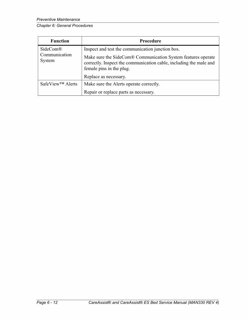
Preventive Maintenance Chapter 6: General Procedures
Function Procedure
SideCom® Communication System
Inspect and test the communication junction box.
Make sure the SideCom® Communication System features operate correctly. Inspect the communication cable, including the male and female pins in the plug.
Replace as necessary. SafeView™ Alerts Make sure the Alerts operate correctly.
Repair or replace parts as necessary.
Page 6 - 12 CareAssist® and CareAssist® ES Bed Service Manual (MAN330 REV 4)
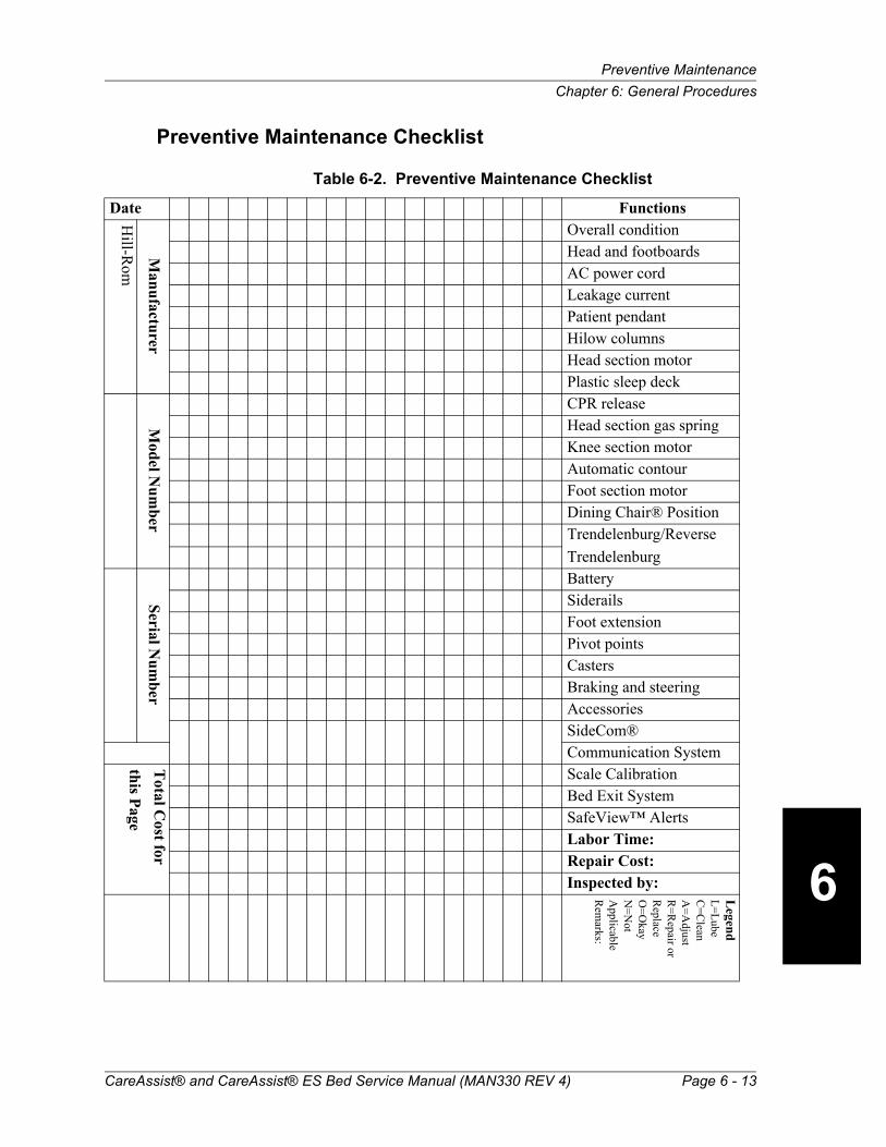
Preventive Maintenance Chapter 6: General Procedures
Preventive Maintenance Checklist
Table 6-2. Preventive Maintenance Checklist
Date Functions
Hill-R
om
Manufacturer
Overall condition Head and footboards AC power cord Leakage current Patient pendant Hilow columns Head section motor Plastic sleep deck
Model N
umber
CPR release Head section gas spring Knee section motor Automatic contour Foot section motor Dining Chair® Position Trendelenburg/Reverse Trendelenburg
Serial Num
ber
Battery Siderails Foot extension Pivot points Casters Braking and steering Accessories SideCom® Communication System
Total C
ost forthis Page
Scale Calibration Bed Exit System SafeView™ Alerts Labor Time: Repair Cost: Inspected by:
Legend
L=Lube C
=Clean
A=A
djust R
=Repair or
Replace
O=O
kay N
=Not
Applicable
Rem
arks:
6
CareAssist® and CareAssist® ES Bed Service Manual (MAN330 REV 4) Page 6 - 13
6.1 Scale Calibration Chapter 6: General Procedures
6.1 Scale Calibration Tools required: T25 Torx®1 screwdriver
250 lb (113 kg) of weight in 25 lb (11 kg) increments
1. Make sure the sleep deck is flat.
2. Remove the mattress and footboard.
3. If a load beam was replaced, do as follows, or go to step 3: a. Place the 250 lb (113 kg) weight over the load beam. b. Wait 1 minute, then remove the weight.
4. Raise the head section to the highest position.
5. Remove the four screws (A) that attach the battery cover (B) to the power supply (C) (see figure 6-1 on page 6-15).
6. Remove the battery cover (B).
7. For C model and newer beds, make sure the load cells are connected to the correct connector on the scale P.C. board as follows: a. Lift up on each corner of the weigh frame. b. Make sure the indicator on the scale P.C. board comes on for the correct
position: P1 is left head, P2 is left foot, P3 is right foot, and P4 is right head.
c. Make corrections as necessary.
8. Lower the head section.
9. Put 25 lb (11 kg) of weight in the center of the bed. Do not put thecalibration weight on the bed at this time.
SHOCK HAZARD: The potential for electrical shock exists with electrical equipment. Failure to follow facility protocols may cause death or serious personal injury.
10. Press and release the calibration switch (D) on the scale P.C. board (E). The display changes to 45.0.
NOTE: If the scale P.C. board was changed, the scale display will only show kilograms until the scale is calibrated and the display has been changed to pounds (lb).
1. Torx® is a registered trademark of Acument Intellectual Properties, LLC.
Page 6 - 14 CareAssist® and CareAssist® ES Bed Service Manual (MAN330 REV 4)
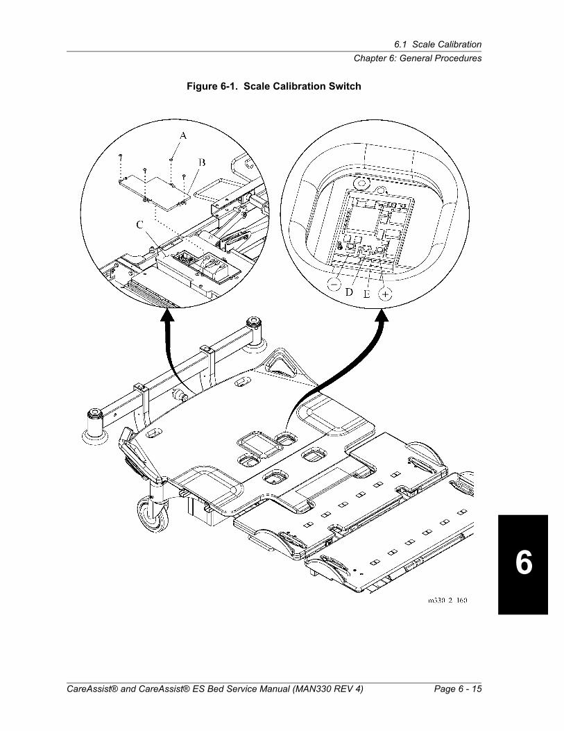
6.1 Scale Calibration Chapter 6: General Procedures
Figure 6-1. Scale Calibration Switch
6
CareAssist® and CareAssist® ES Bed Service Manual (MAN330 REV 4) Page 6 - 15
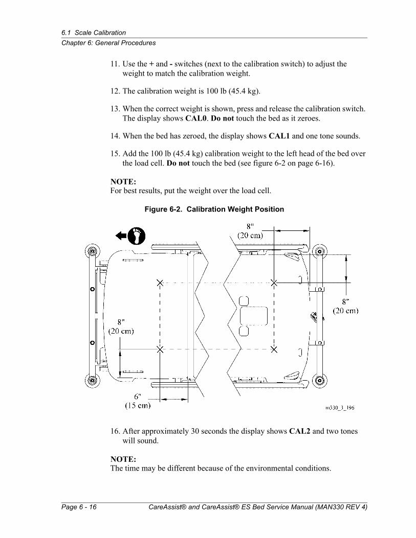
6.1 Scale Calibration Chapter 6: General Procedures
11. Use the + and - switches (next to the calibration switch) to adjust the weight to match the calibration weight.
12. The calibration weight is 100 lb (45.4 kg).
13. When the correct weight is shown, press and release the calibration switch. The display shows CAL0. Do not touch the bed as it zeroes.
14. When the bed has zeroed, the display shows CAL1 and one tone sounds.
15. Add the 100 lb (45.4 kg) calibration weight to the left head of the bed over the load cell. Do not touch the bed (see figure 6-2 on page 6-16).
NOTE: For best results, put the weight over the load cell.
Figure 6-2. Calibration Weight Position
16. After approximately 30 seconds the display shows CAL2 and two tones will sound.
NOTE: The time may be different because of the environmental conditions.
Page 6 - 16 CareAssist® and CareAssist® ES Bed Service Manual (MAN330 REV 4)
6.1 Scale Calibration Chapter 6: General Procedures
17. Remove the calibration weight. Do not touch the bed.
18. After approximately 30 seconds, the display shows CAL3 and three tones sound.
19. Add the calibration weight to the left foot of the bed over the load cell. Do not touch the bed.
20. After approximately 30 seconds, the display shows CAL4 and four tones sound.
21. Remove the calibration weight. Do not touch the bed.
22. After approximately 30 seconds, the display changes to CAL5 and five tones sound.
23. Add the calibration weight to the right foot of the bed, over the load cell. Do not touch the bed.
24. After approximately 30 seconds, the display changes to CAL6 and six tones sound.
25. Remove the calibration weight. Do not touch the bed.
26. After approximately 30 seconds, the display changes to CAL7 and seven tones sound.
27. Add the calibration weight to the right head of the bed over the load cell. Do not touch the bed.
28. After approximately 30 seconds, the bed beeps.
NOTE: B model beds may not beep depending on the volume.
29. Move the calibration weight to the middle of the bed.
30. Take a weight reading.
31. Make sure the weight shown on the scale display matches the calibration weight.
32. Remove the calibration weight.
33. Raise the head section to the highest position.
6
CareAssist® and CareAssist® ES Bed Service Manual (MAN330 REV 4) Page 6 - 17
6.1 Scale Calibration Chapter 6: General Procedures
WARNING: Failure to unplug the bed could cause personal injury or equipment damage.
34. Unplug the bed from its power source. Let the bed sit for 60 seconds for the battery to time out.
35. Install the battery cover (B) on the power supply (C) (see figure 6-1 on page 6-15).
36. Install the four screws (A) to attach the battery cover (B) to the power supply).
37. Plug the bed into an applicable power source.
38. Do the “Function Checks” on page 2-4.
Page 6 - 18 CareAssist® and CareAssist® ES Bed Service Manual (MAN330 REV 4)
Chapter 7 Accessories
Accessories
Table 7-1. Accessories List
Product Number Description
P158A Infusion Support System (ISS) Transfer Pole P27601 Oxygen Tank Holder P2217 IV Pole P734EA1 Mattress Pad Extender P731EA3 Mattress P163 ISS Socket Adapter P1181B Traction frame support module P1180 Patient Helper Support P1176 Patient Helper, Fixed Position, kit P1177 Patient Helper, Adjustable Position, kit
7 CareAssist® and CareAssist® ES Bed Service Manual (MAN330 REV 4) Page 7 - 1
7.1 Infusion Support System—P158 Chapter 7: Accessories
7.1 Infusion Support System—P158 Tools required: None
The Infusion Support System (ISS) consists of a movable and adjustable IV rod that attaches to the head end of the system. The pole supports IV pumps or bags in a vertical orientation and raises or lowers the pumps or bags with respect to the bed frame.
Each Infusion Support System can support one infusion pump plus two liters of intravenous solution.
Installation
WARNING: Do not exceed ISS pole weight capacity. Personal injury or equipment damage could occur.
WARNING: When lowering the upper section of an ISS pole, always grasp and hold the upper section of the pole before twisting the release knob. Failure to do so could cause personal injury or equipment damage.
1. Install the P163 adapter into any of the four equipment sockets.
2. Install the ISS pole into the adapter.
3. Hang up to 40 lb (18 kg) on the ISS pole.
CAUTION: Do not mount infusion pumps on the lower section of an IV rod. Interference with head section articulation could result.
4. Hang pumps on the upper section of an ISS pole.
Removal
Do the installation procedure in reverse order.
Page 7 - 2 CareAssist® and CareAssist® ES Bed Service Manual (MAN330 REV 4)
7.2 Oxygen Tank Holder—P27601 Chapter 7: Accessories
7.2 Oxygen Tank Holder—P27601 Tools required: None
The oxygen tank holder attaches to the bed in a vertical position. The Oxygen Tank Holder accommodates one E-size oxygen tank with a regulator. The mounting points are located at each corner of the bed and permit the affixed oxygen tank holders to pivot.
WARNING: If the oxygen tank holder is placed at the foot end of the bed, make sure the Knee Up/Down controls are locked out. Failure to do so can cause caregiver, patient, or visitor injury if the foot section fully lowers and the holder becomes dislodged from the bed.
Installation
1. Install the mounting bar vertically into an equipment socket at any corner of the bed.
2. Place one E-size oxygen tank in the holder.
3. Tighten the holder thumbscrew.
NOTE: The thumbscrew keeps the oxygen tank from rotating in the holder.
Removal
1. Loosen the thumbscrew that holds the tank securely in the holder.
2. Lift the tank out of the holder.
3. Lift up on the tank holder, and remove it from the equipment socket.
7 CareAssist® and CareAssist® ES Bed Service Manual (MAN330 REV 4) Page 7 - 3
7.3 IV Pole—P2217 Chapter 7: Accessories
7.3 IV Pole—P2217 Tools required: None
The IV pole is a removable, telescopic pole that installs at any of the four corners of the system in the holes provided.
WARNING: Do not exceed IV rod weight capacity, personal injury or equipment damage could result.
WARNING: When lowering the upper section of an IV rod, always grasp and hold the upper section of the pole before pulling the release knob. Failure to do so could cause personal injury or equipment damage.
Installation
Install the IV rod in an equipment socket at any corner of the bed.
Removal
Reverse the installation procedure to remove the IV Rod.
Page 7 - 4 CareAssist® and CareAssist® ES Bed Service Manual (MAN330 REV 4)
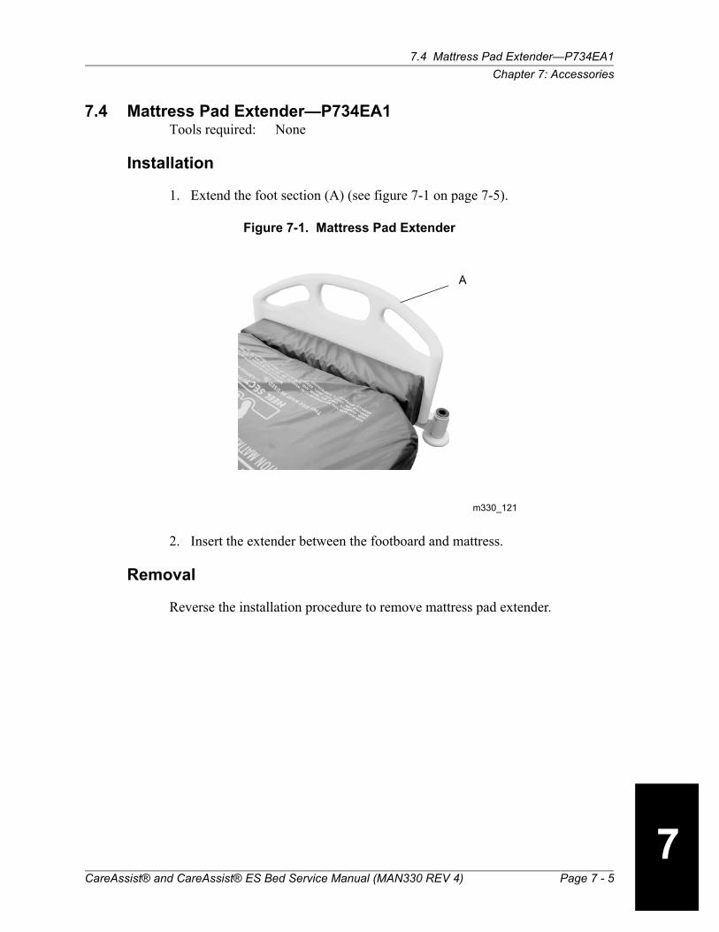
7.4 Mattress Pad Extender—P734EA1 Chapter 7: Accessories
7.4 Mattress Pad Extender—P734EA1 Tools required: None
Installation
1. Extend the foot section (A) (see figure 7-1 on page 7-5).
Figure 7-1. Mattress Pad Extender
A
m330_121
2. Insert the extender between the footboard and mattress.
Removal
Reverse the installation procedure to remove mattress pad extender.
7 CareAssist® and CareAssist® ES Bed Service Manual (MAN330 REV 4) Page 7 - 5
7.5 Mattress—P731EA3 Chapter 7: Accessories
7.5 Mattress—P731EA3 Tools required: None
Installation
1. Lower all four siderails.
2. Set the mattress on the sleep deck.
Removal
Reverse the installation procedure to remove the mattress.
Page 7 - 6 CareAssist® and CareAssist® ES Bed Service Manual (MAN330 REV 4)
7.6 Traction Frame Support Module—P1181B Chapter 7: Accessories
7.6 Traction Frame Support Module—P1181B Tools required: 19mm wrench
Ratchet Torque wrench,5 to 75 ft-lb (7 to 102 N·m)
Installation
1. Set the brakes.
2. Raise the bed to the full up position.
SHOCK HAZARD: Failure to unplug the bed could cause personal injury or equipment damage.
3. Unplug the bed from its power source. Let the bed sit for 60 seconds to let the battery time out.
4. Do as follows for each side:
a. Install one bolt (A) and washer (F) in the inner hole (B) of the module (C) ((see figure 7-2 on page 7-8)).
b. Install, but do not tighten, one nut plate (D) on the bolt (A).
5. Move the module (C) under the bed (E).
6. Lift the module (C) so it touches the bottom of the bed (E).
7. Turn the nut plate (D) so that it supports the weight of the module (C).
8. Install two bolts (A) and washer (F) through the outer holes in the module (C) and into the nut plate (D).
9. Slide the module (C) so it is against the hilow tower.
10. Tighten all four bolts (A) to 40 ft-lb (54 N·m) of torque.
7 CareAssist® and CareAssist® ES Bed Service Manual (MAN330 REV 4) Page 7 - 7
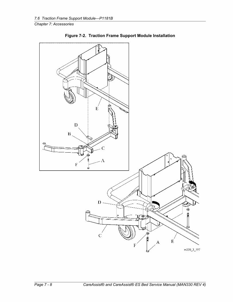
7.6 Traction Frame Support Module—P1181B Chapter 7: Accessories
Figure 7-2. Traction Frame Support Module Installation
Page 7 - 8 CareAssist® and CareAssist® ES Bed Service Manual (MAN330 REV 4)
7.6 Traction Frame Support Module—P1181B Chapter 7: Accessories
Removal
Reverse the installation procedure to remove the traction frame.
7 CareAssist® and CareAssist® ES Bed Service Manual (MAN330 REV 4) Page 7 - 9

7.6 Traction Frame Support Module—P1181B Chapter 7: Accessories
NOTES:
Page 7 - 10 CareAssist® and CareAssist® ES Bed Service Manual (MAN330 REV 4)
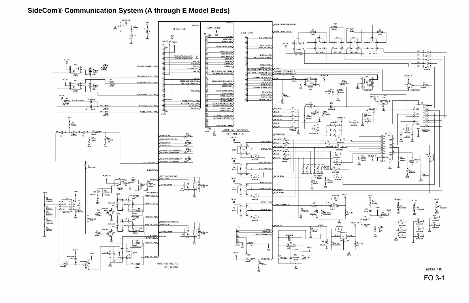
SideCom® Communication System (A through E Model Beds)
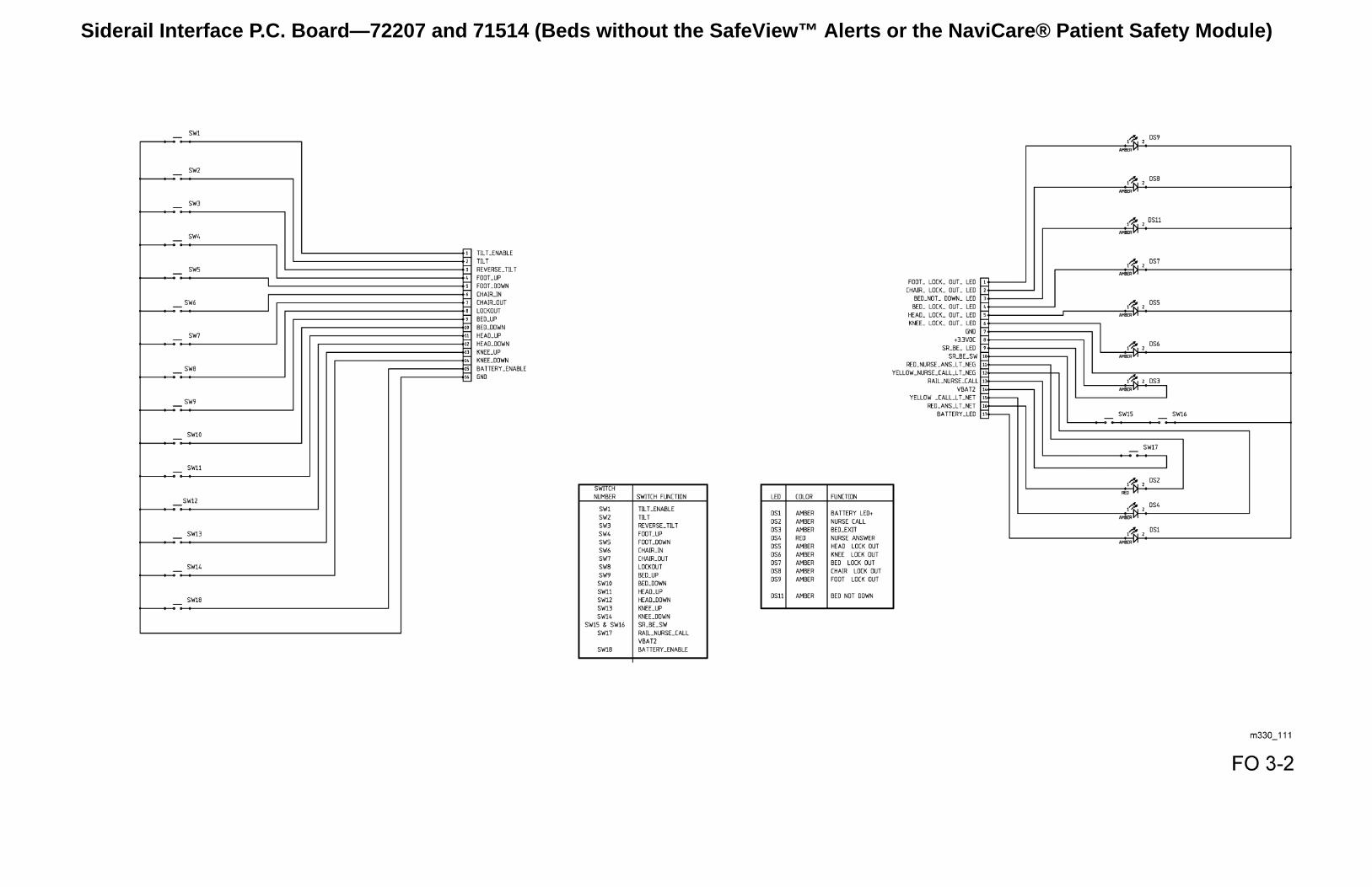
Siderail Interface P.C. Board—72207 and 71514 (Beds without the SafeView™ Alerts or the NaviCare® Patient Safety Module)
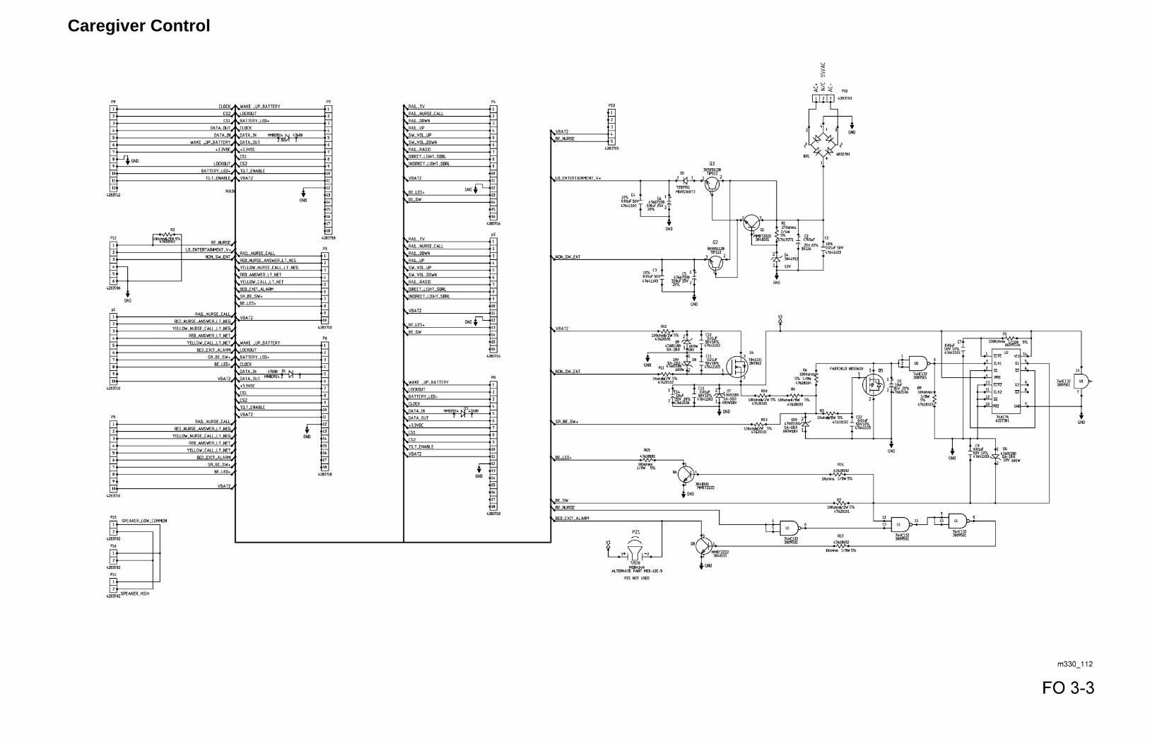
Caregiver Control
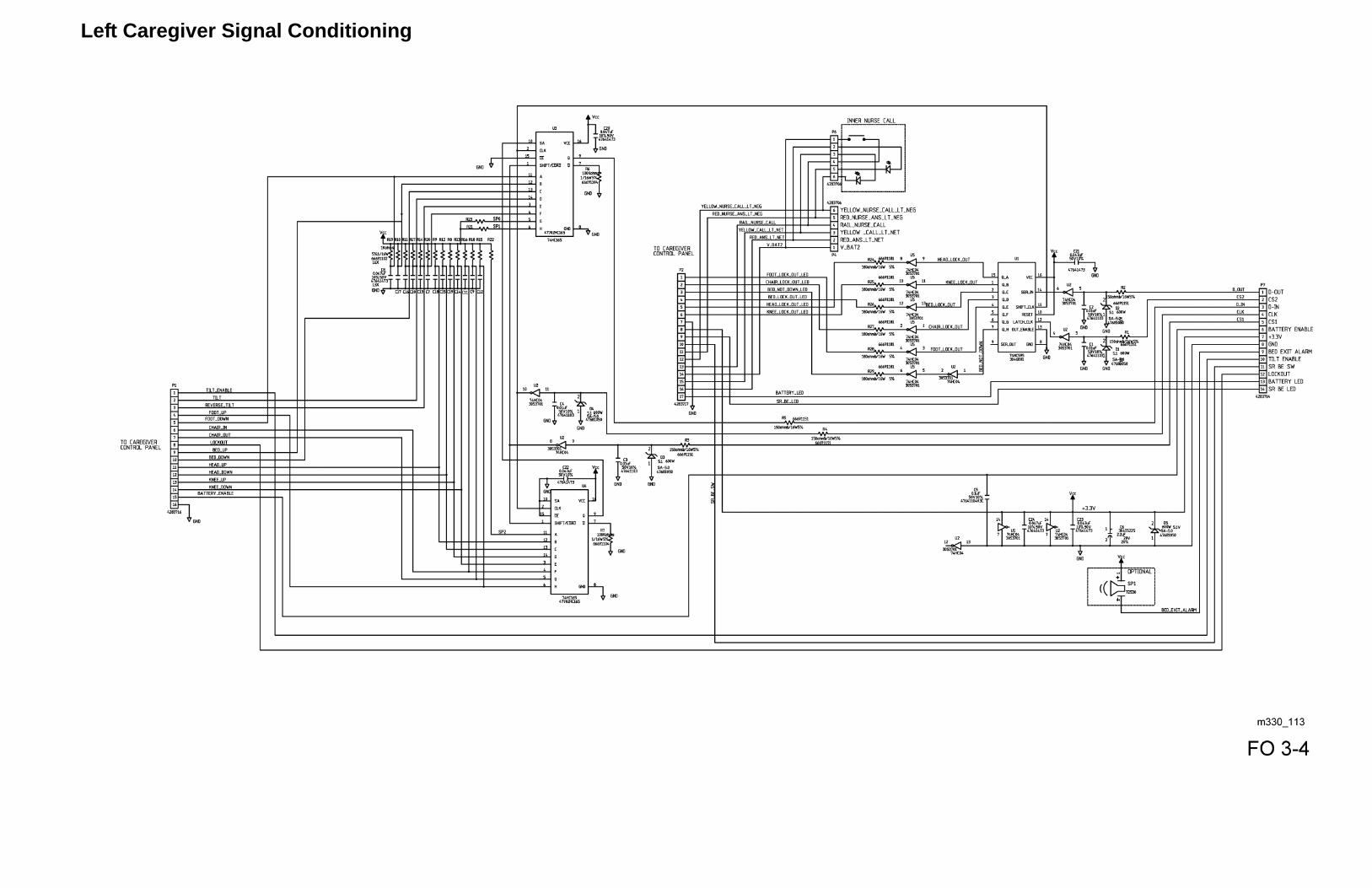
Left Caregiver Signal Conditioning
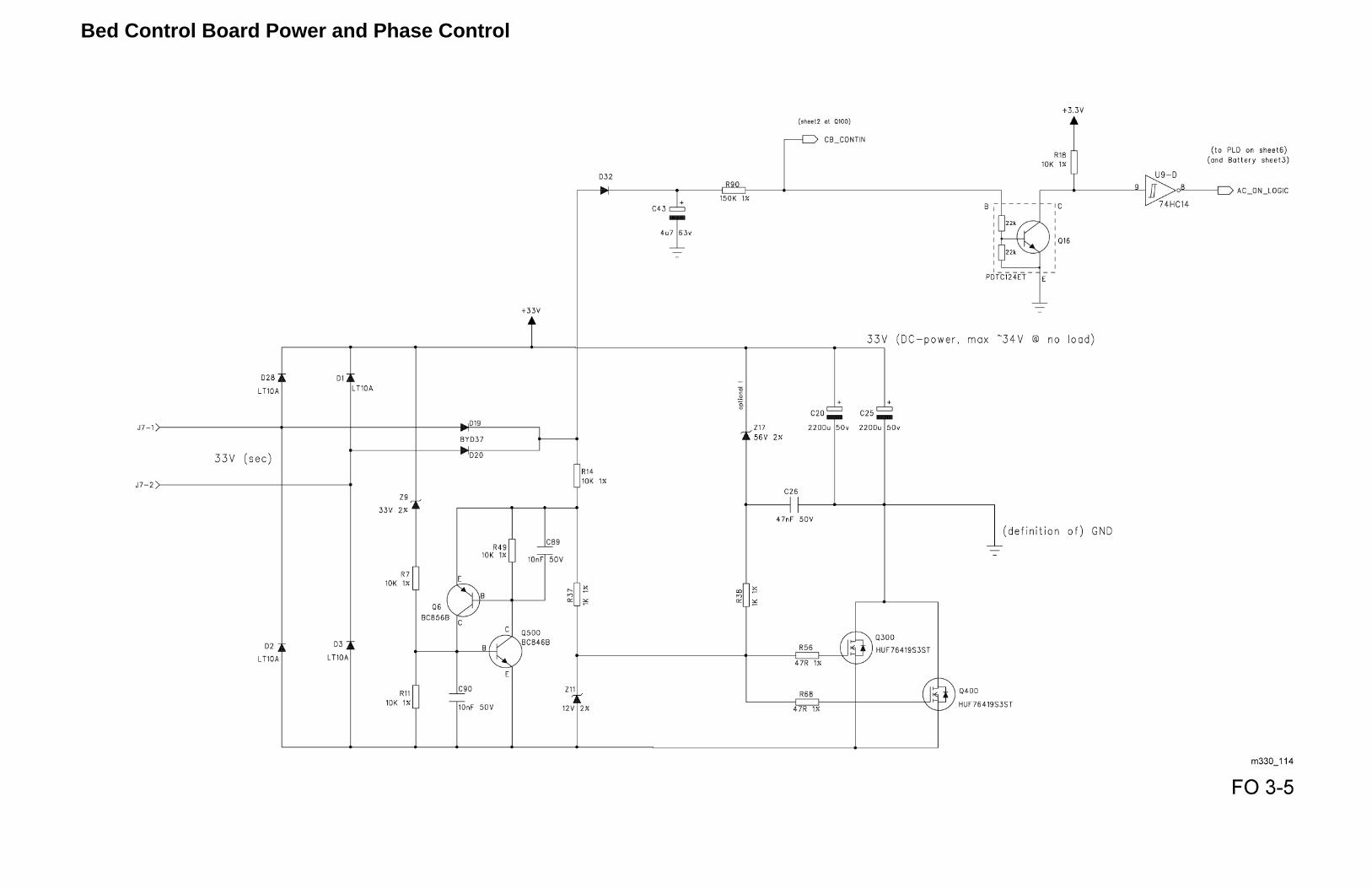
Bed Control Board Power and Phase Control
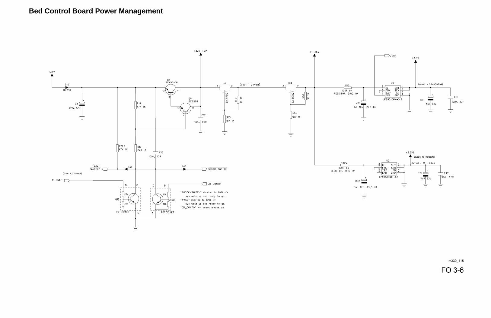
Bed Control Board Power Management
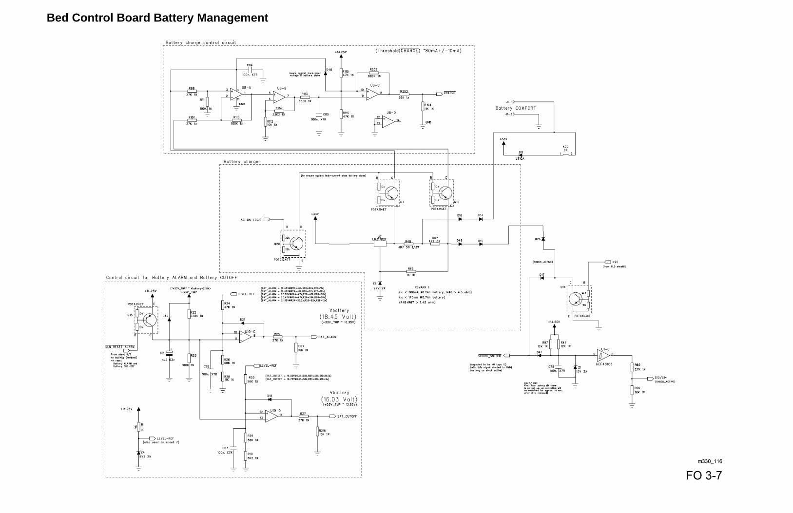
Bed Control Board Battery Management
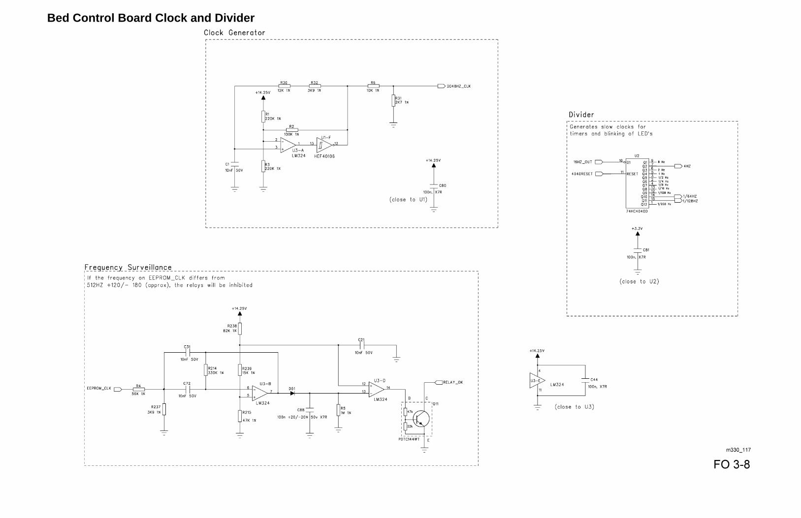
Bed Control Board Clock and Divider
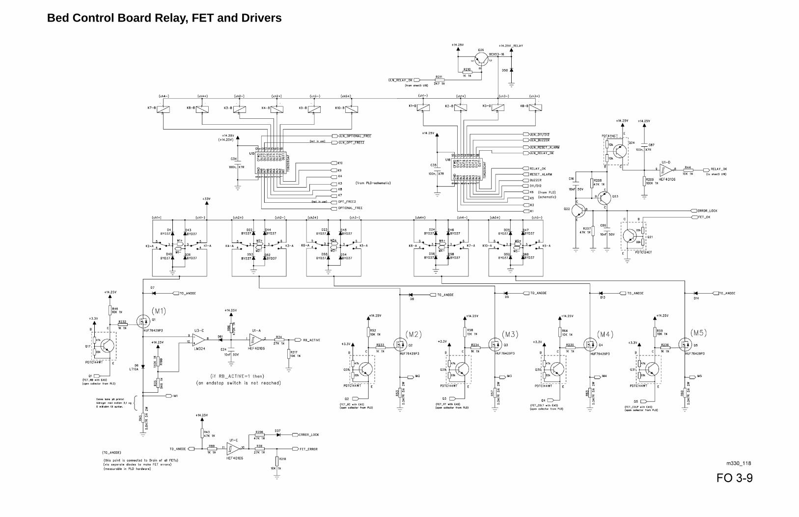
Bed Control Board Relay, FET and Drivers
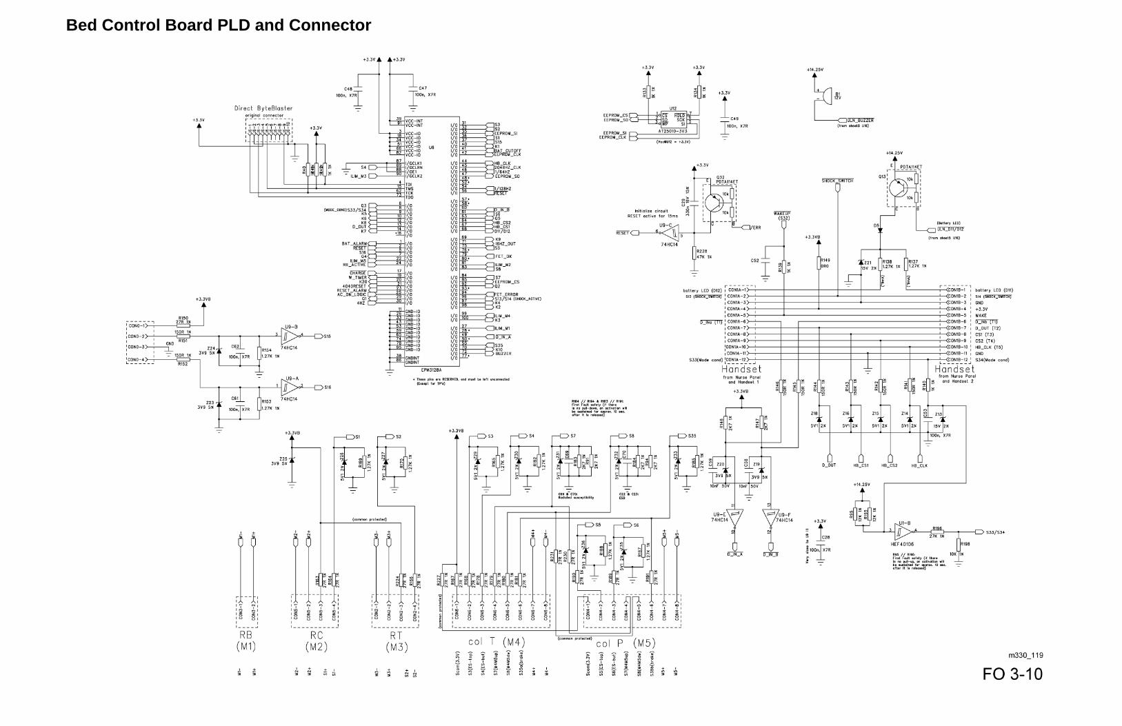
Bed Control Board PLD and Connector
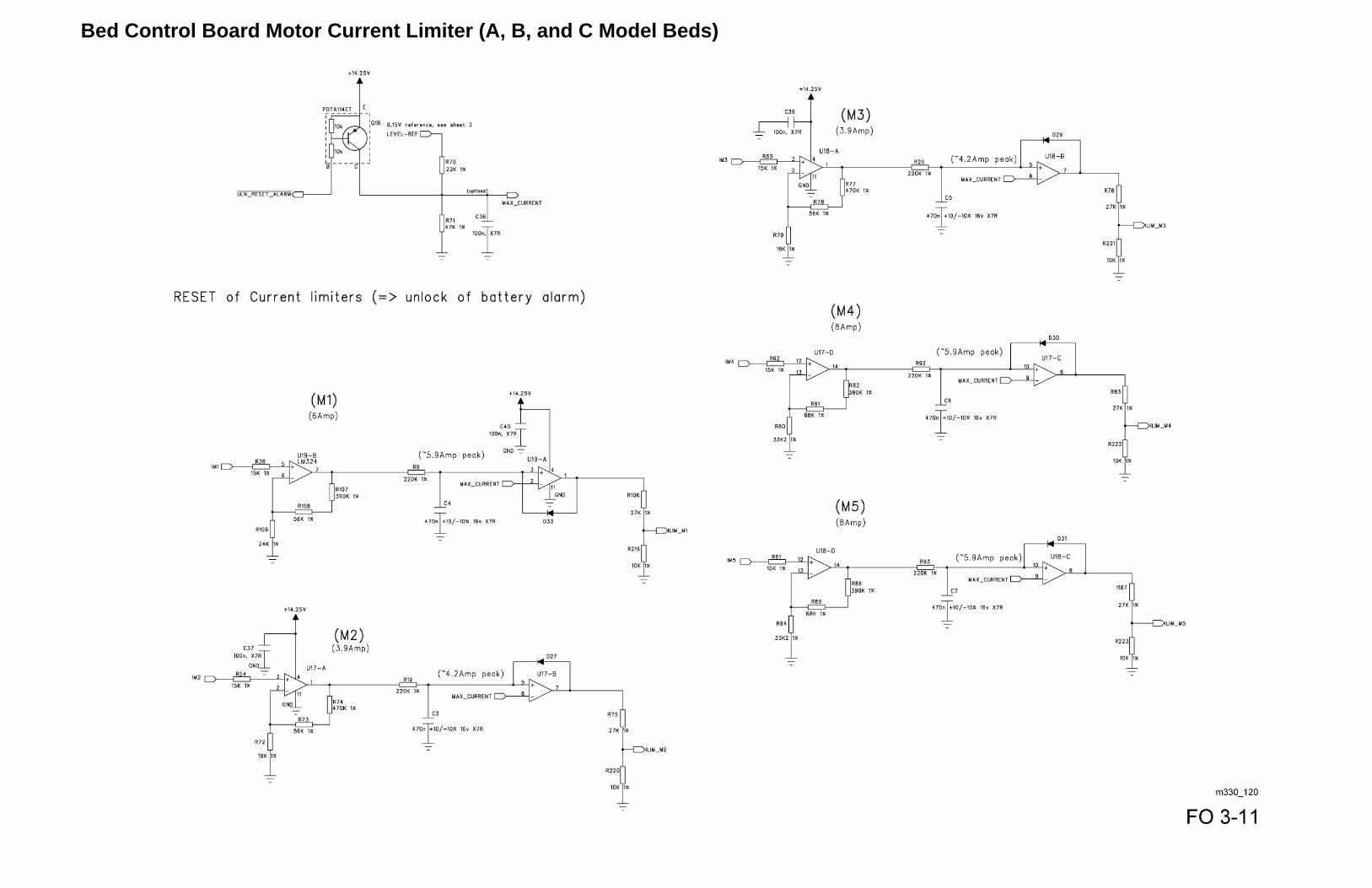
Bed Control Board Motor Current Limiter (A, B, and C Model Beds)
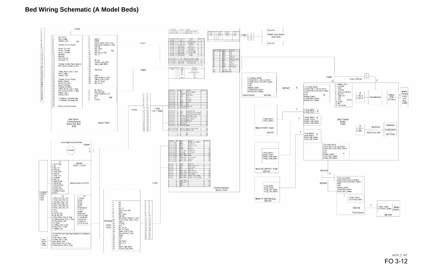
Bed Wiring Schematic (A Model Beds)
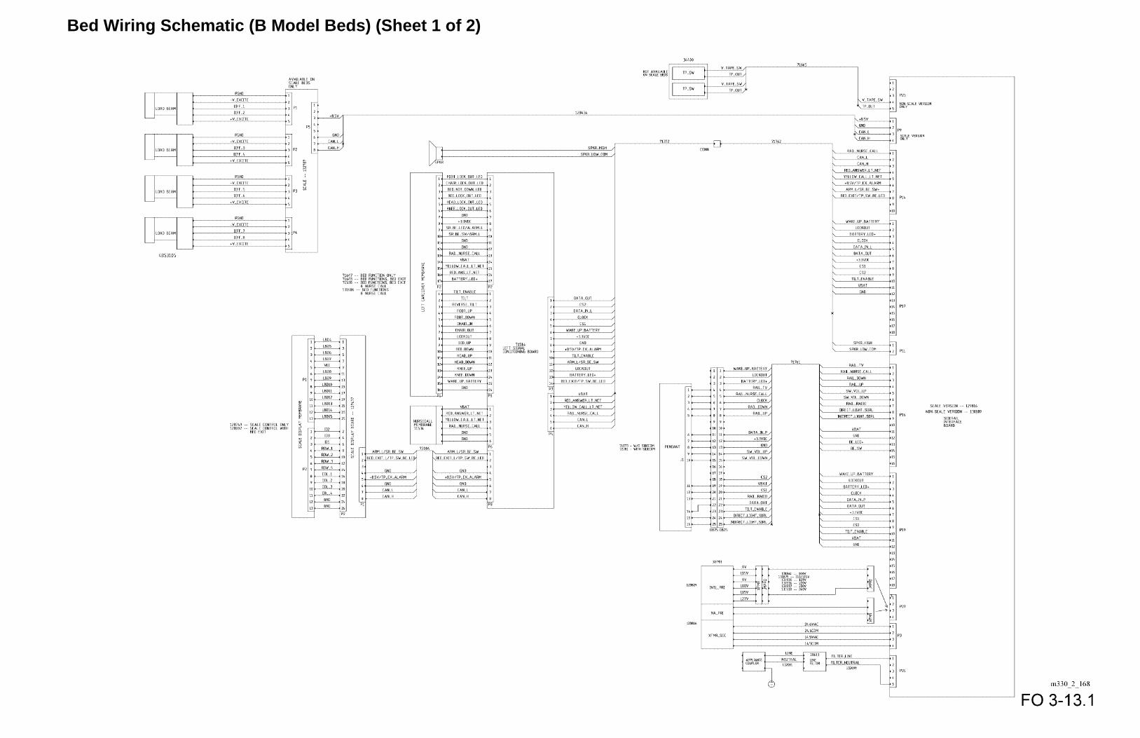
Bed Wiring Schematic (B Model Beds) (Sheet 1 of 2)
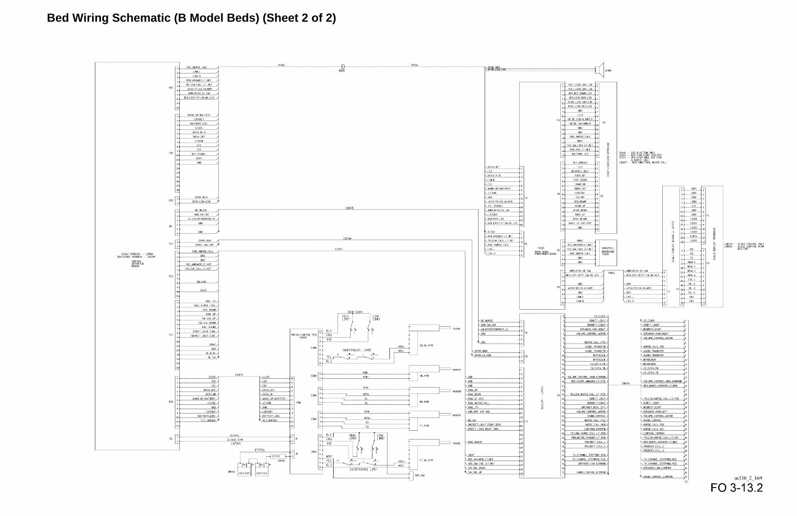
Bed Wiring Schematic (B Model Beds) (Sheet 2 of 2)
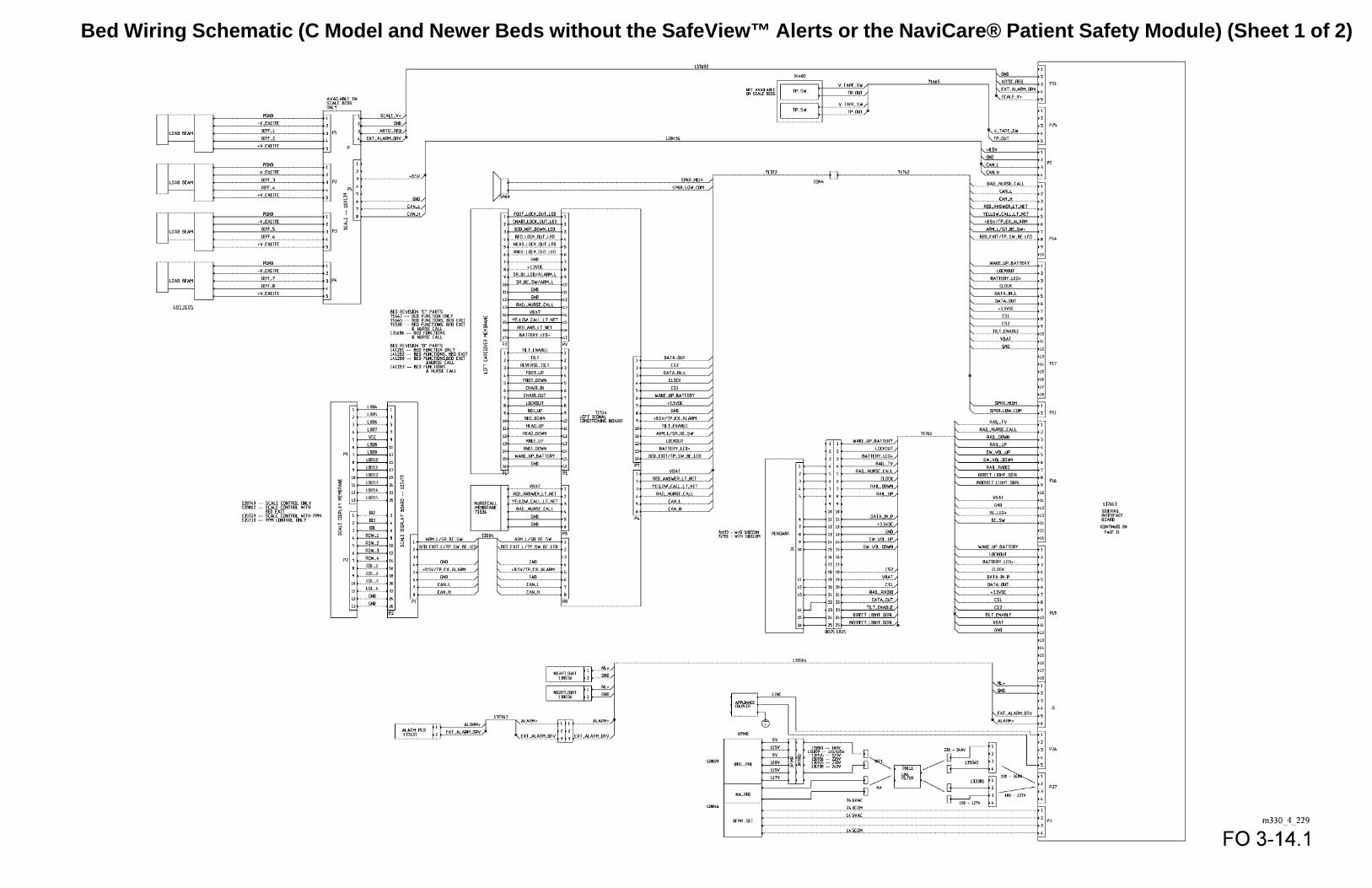
Bed Wiring Schematic (C Model and Newer Beds without the SafeView™ Alerts or the NaviCare® Patient Safety Module) (Sheet 1 of 2)
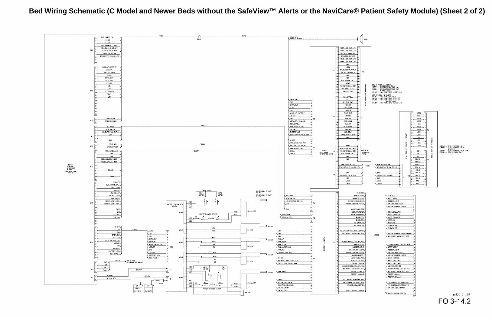
Bed Wiring Schematic (C Model and Newer Beds without the SafeView™ Alerts or the NaviCare® Patient Safety Module) (Sheet 2 of 2)
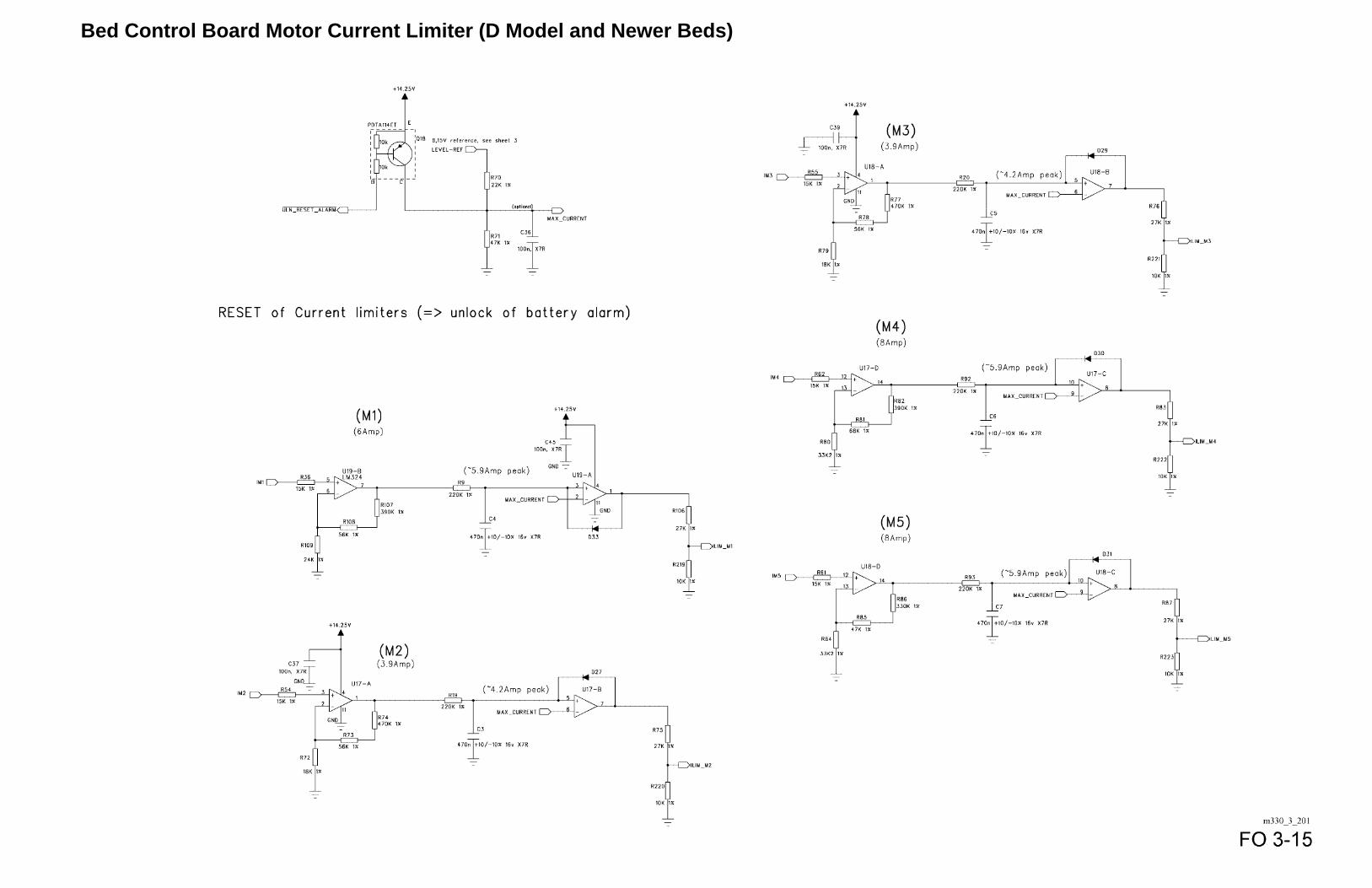
Bed Control Board Motor Current Limiter (D Model and Newer Beds)
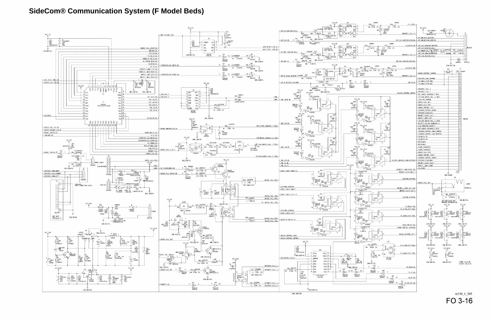
SideCom® Communication System (F Model Beds)
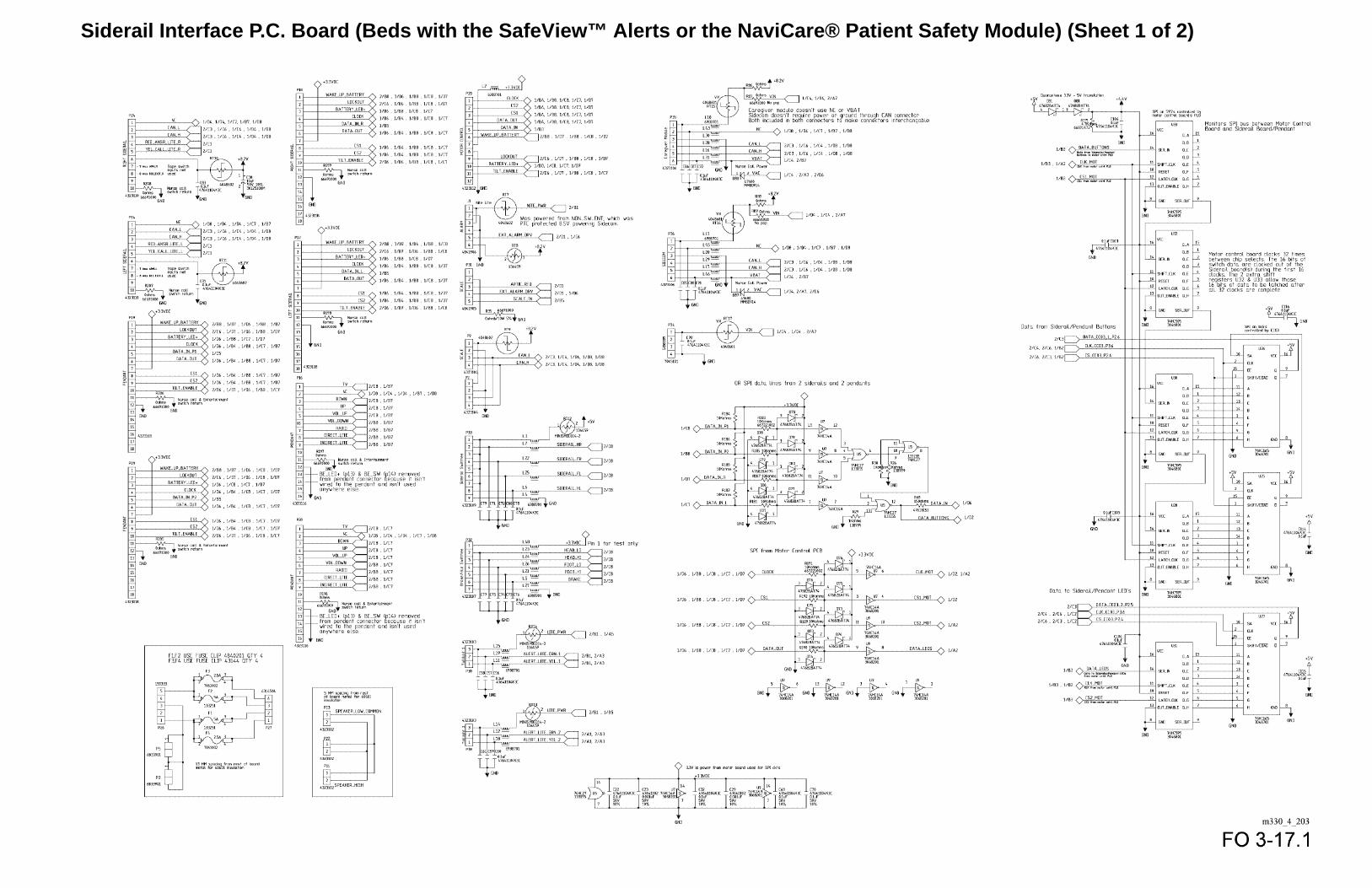
Siderail Interface P.C. Board (Beds with the SafeView™ Alerts or the NaviCare® Patient Safety Module) (Sheet 1 of 2)
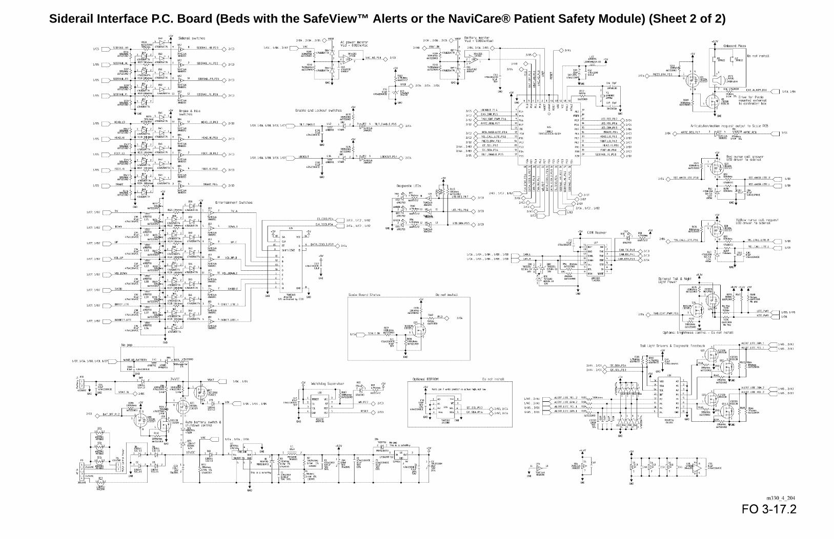
Siderail Interface P.C. Board (Beds with the SafeView™ Alerts or the NaviCare® Patient Safety Module) (Sheet 2 of 2)
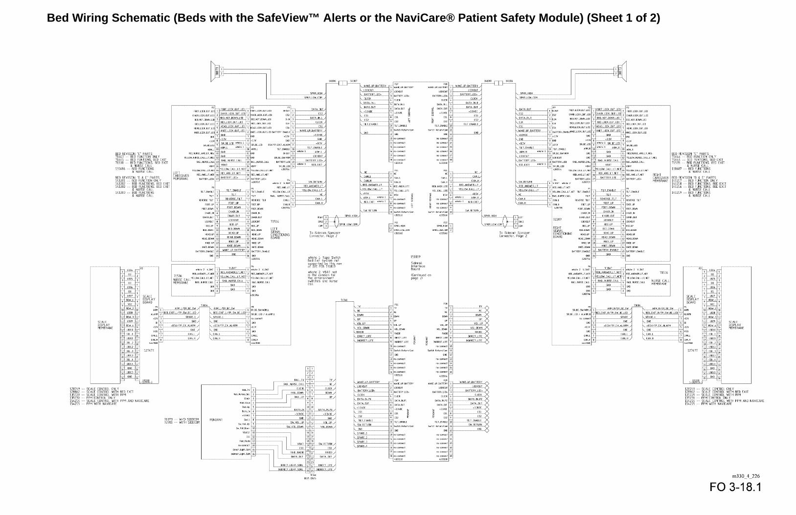
Bed Wiring Schematic (Beds with the SafeView™ Alerts or the NaviCare® Patient Safety Module) (Sheet 1 of 2)
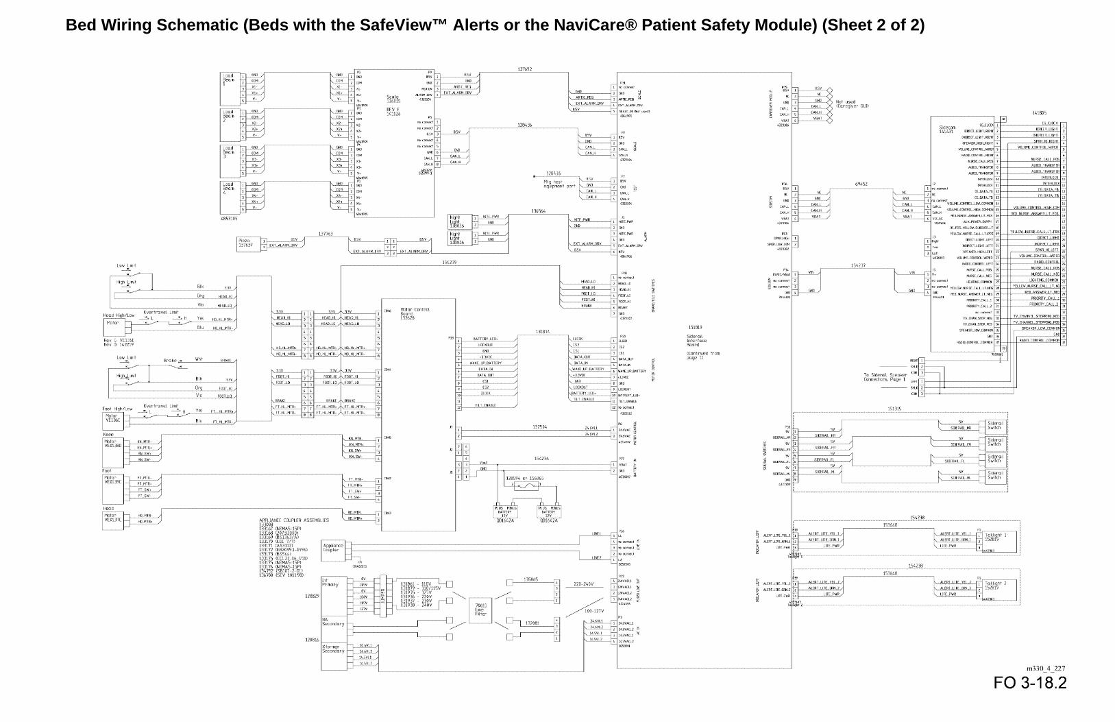
Bed Wiring Schematic (Beds with the SafeView™ Alerts or the NaviCare® Patient Safety Module) (Sheet 2 of 2)

US Rental Therapy Hill-Rom Company, Inc.
Tel: 800-638-2546
Australia Hill-Rom Australia Pty. Ltd.
Tel: +61 (0)2 8814 3000 Fax: +61 (0)2 8814 3030
Hill-Rom Shanghai Tel: +86 (0)21 5396 6933 Fax: +86 (0)21 5383 3136
France Hill-Rom SAS
Tel: +33 (0)2 97 50 92 12 Service: +33 (0)820 01 23 45
Fax: +33 (0)2 97 50 92 00
Italia Hill-Rom S.p.A.
Tel: +39 (0)02 / 950541 Fax: +39 (0)02 / 95328578
Nederland Hill-Rom Medical Services BV
Tel: +31 (0)347 / 32 35 32 Fax: +31 (0)347 / 32 35 00
Österreich Hill-Rom Austria GmbH Tel: +43 (0)2243 / 28550
Fax: +43 (0)2243 / 28550-19 [email protected]
Suisse/Schweiz Hill-Rom SA
Tel: +41 (0)21 / 706 21 30 Fax: +41 (0)21 / 706 21 33
hrch.info@hill-rom
St. Paul, MN Hill-Rom Company, Inc.
Tel: 651-490-1468 or 800-426-4224 www.thevest.com
Belgique/België Hill-Rom Medical Services BV
Tel: +31 (0)347 / 32 35 32 Fax: +31 (0)347 / 32 35 00
Deutschland Hill-Rom GmbH
Tel: +49 (0)211 16450 0 Fax: +49 (0)211 16450 182
Hong Kong Hill-Rom Asia Ltd.
Tel: +852 (0)2297-2395 Fax: +852 (0)2297-0090
Hill-Rom Japan Tel: +81 (0)3 5715 3420 Fax: +81 (0)3 5715 3425
New Zealand Hill-Rom Australia Pty. Ltd.
Tel: +61 (0)2 8814 3000 Fax: +61 (0)2 8814 3030
Portugal Hill-Rom Iberia S.L.
Tel: +34 (0)93 685 6009 Fax: +34 (0)93 666 5570
United Kingdom Hill-Rom Ltd.
Tel: +44 (0)1530 411000 Fax: +44 (0)1530 411555
Global Headquarters US Hill-Rom Company, Inc. 1069 State Route 46 E
Batesville, IN 47006-9167 Tel: 800-445-3720 www.hill-rom.com
International Hill-Rom Company, Inc. Tel: +1 (0)812 934 8173 Fax: +1 (0)812 934 7191
www.hill-rom.com [email protected]
Canada Hill-Rom Canada Tel: 800-267-2337
España Hill-Rom Iberia S.L.
Tel: +34 (0)93 685 6009 Fax: +34 (0)93 666 5570
Ireland Hill-Rom Ltd.
Tel: +353 (0)1 413 6005 Fax: +353 (0)1 413 6030
c/o Hill-Rom Japan Tel: +81 (0)3 5715 3420 Fax: +81 (0)3 5715 3425
Nordic Region: Sverige, Denmark, Norge
Hill-Rom AB Tel: +46 (0)8 564 353 60 Fax: +46 (0)8 564 353 61
South East Asia Hill-Rom Singapore
Tel: +65 (0)6391 1322 Fax: +65 (0)6391 1324