Embed Size (px)
Citation preview

Cardax N32C, N32R, N32KP the access control system for your company
Doc. 30104/15.11.01/BETA VERSION
USER MANUAL
User Manual CARDAX Access Control System
2
Contents
1. SYSTEM DESCRIPTION ................................................................................................................ 3 1.1. What is an Access Control System.......................................................................................... 3 1.2. CARDAX features .................................................................................................................. 3 1.3. CARDAX specifics .................................................................................................................. 5 2. CARDAX COMPONNENTS ............................................................................................................. 8 2.1. Central Unit Cardax N32C ...................................................................................................... 8 2.2. Indoor access keypad Cardax N32KP...................................................................................... 9 2.3. Card code interface module Cardax N32R..............................................................................10 2.4. Monitoring software and Presence software...........................................................................11 2.4.1. Monitoring software.......................................................................................................11 2.4.2. Presence software .........................................................................................................12 3. USING CARDAX SYSTEM .............................................................................................................13 3.1. Using the system: card holders .............................................................................................13 3.2. Using the system: dispatchers ..............................................................................................13
User Manual CARDAX Access Control System
3
1. SYSTEM DESCRIPTION
1.1. What is an Access Control System Generally speaking, an Access Control System may fulfil the following requests:
- restrict the personal access in the supervised areas upon different criteria: - allowed persons (code based access); - specific areas (access levels; zones); - specific time intervals (schedules); - restrictions ENTRY-EXIT (antipassback); - restrictions for the access path.
- Deny the access for unauthorised personnel and report the intrusion; - Remotely granting access (from PC, by remote control, etc.); - Event management and event reporting; - Interaction with other system as: burglary systems, fire alarms, CCTV, etc.
1.2. CARDAX features • 6000 user codes (extension up to 14000); • event log buffer: 2500 events ; • up to 32 access points supervision; • area extents - 1200m maximum cable length ( the access modules are wired together on RS485 serial
bus); • modularity (the system has one central unit and several periferic modules); • RS485 serial bus for modules communication; • RS232 serial interface for PC communication; • System programming by PC:
• 100 access levels (zones); • 20 week schedules, with possibility to configure holidays; • periferic modules parameters; • user codes;
• the system supports magnetic card readers, proximity card readers and keypad codes • Once configured, the system may work independently (the PC is not needed). • Power supply: 220 Vac for Cardax N32C and Cardax N32R; 12 -16 Vdc for Cardax N32KP; • When power fails, the system configuration and event log is backed up by means of a 3.6 V Ni-Cd
battery on the ventral unit; • Monitoring software with features:
• System programming; • Real-time event monitoring; • Real-time access point status monitoring; • Building map • Event reporting; • File management; • The events are stored in a coded format (needed for internally generated reports) and in DBF format
to easily user management. • Time-attendance software.
User Manual CARDAX Access Control System
4
Terms Central Unit: Defines equipment able to communicate with up to 32 periferic modules. It stores the system database and the system event log. The central unit for CARDAX system is represented by the Cardax N32C module.
Periferic Module: Defines equipment able to control and monitor an access point. In Cardax system, the periferic modules are Cardax N32R and Cardax N32KP. As a detail, the central unit PCB incorporates the functions of an Cardax N32R module.
RIM – Reader Interface Module: Defines equipment able to translate the signals from the card (code) reader. In Cardax system these interfaces are present on the central unit and on the Cardax N32R periferic modules.
Access Point: It’s a zone through which the access could be granted in a supervised area. Each access point is controlled by a peripheral module.
PC – Personal Computer: On the PC there runs the monitoring software and, eventually, the time & attendance software. Data received by the central unit is sent to PC as events. With these events, the software displays the status of the control access system and generates reports.
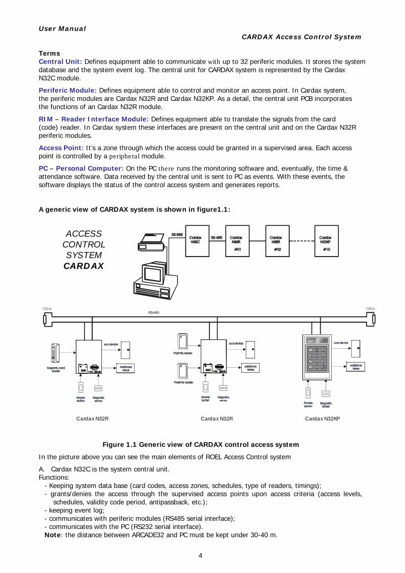
A generic view of CARDAX system is shown in figure1.1:
Figure 1.1 Generic view of CARDAX control access system
In the picture above you can see the main elements of ROEL Access Control system
A. Cardax N32C is the system central unit. Functions:
- Keeping system data base (card codes, access zones, schedules, type of readers, timings); - grants/denies the access through the supervised access points upon access criteria (access levels,
schedules, validity code period, antipassback, etc.); - keeping event log; - communicates with periferic modules (RS485 serial interface); - communicates with the PC (RS232 serial interface). Note: the distance between ARCADE32 and PC must be kept under 30-40 m.
Cardax N32R Cardax N32R Cardax N32KP
RS-485
ACCESS CONTROL SYSTEMCARDAX
User Manual CARDAX Access Control System
5
B. Cardax N32R is a peropheral module that can assume two magnetic or proximity card readers to work with. The module controls a single access point in both directions (entry/exit). On demand, an access button could be used to in addition to the card readers.
C. Cardax N32KP is a peripheral module that accepts keypad codes. It does not incorporate stabilized 12V
power supply. The module controls a single access point, in one direction. To control the access point in both directions means mounting two modules together at same access point.
Cardax N32R or Cardax N32KP functions are: - Detection of access point status by means of magnetic sensor; - Detection of access button trigger; - Manages the lock device; - Communicates with central unit Cardax N32C through RS485 serial line; - Reads the access code from card readers or keypads; - Triggers on-board additional relays upon events issued at the access point (Forced Door, Door
propped, etc.). - Note: Momentarily, you cannot mount Card Readers on one access direction and keypad on the other
direction, using the same Door Sensor. If you want that, you must use a Door Sensor for each equipment.
1.3. CARDAX specifics Data flow The events generated at the access points are managed by the periferic modules Cardax N32R and Cardax N32KP and are communicated to the central unit Cardax N32C. This unit stores the events or send them to the computer when the monitoring software is started on that computer. Depending on the programmed parameters, the central unit take decisions regarding granting/ denying access through the access points. The decision is sent to prripheral modules and executed by them. RS485 module communication Each module of the Cardax system is configured withy a unique address in range 0-31. The central unit polls existing modules and recognizes the response upon this address. The configuration procedure is descrived in the installation manual of each separate module. Cardax N32C is always the master and the modules are always slaves. The number o prripheral modules may be set with the SW1 DIP-SWITCH on the central unit board. RS232 serial comunication When Cardax N32C is connected to a computer and, on that computer, there runs the monitoring software, then the events are immediately transferred to the PC. From PC, the central unit is programmed with the system user codes and access parameters. The access Passing through an access point may be possible by code or directly, by pressing an access button. In the first case, the decision is taken by the central unit, after code validation procedure. The codes could be entered from a keypad (Cardax N32KP) or read from a card shown at a card reader (Cardax N32R or Cardax N32C which has a reader interface incorporated on the board). The access is performed in three steps: - from the moment ARCADE32 validates the access to the moment the door is opened by the user. - passing the door - after passing the door Each step is important to the system by the events produced and reported to Central Unit and finally to PC.
The first step depends on the lock device, and, for the user, it represents the time between the moment the door is released and the moment the door is opened by the user. This time (that we called Lock Relay Time) can be set at 1 to 99 seconds Setting 0 value for this time means two impulses for the Lock Relay, impulses used with electrical strike lock device. If you use electromagnetic lock device, you cannot open the door after the time expires, because then the relay is de-energized. If you use electrical strike lock device, you may open the door even if you try that after two years. In this case, it is important that the system alerts an unperformed access if the Entry/Exit time expires, and the door has not been opened yet. The default Lock Relay Time is 5 seconds.
User Manual CARDAX Access Control System
6
The second step depends on the Entry/Exit Time (or Access Time). This parameter has as default value 10 seconds and may have values from 1 to 99 seconds. On the third step, the Door Position Sensor has the main importance. If the door remains opened after the Entry/Exit time expired, ARCADE01 or KP2N generates a “PROPPED DOOR” event. If the door is closed before time expires, you’ll see just a “DOOR CLOSED” event. If the door has not been opened either during the Lock Relay time or the Entry/Exit time, you’ll see an “UNPERFORMED ACCESS” event on PC display. The access is granted from three places:
- locally, at the access point (pressing the access button); - from the central unit after code validation; - from PC, with a special command.
Access restrictions The access is denied when:
- The code isn’t in the central unit’s database – INTRUDER - The code has no access at the point it was entered – INVALID ZONE - The code has no access at the time it was entered – INVALID SCHEDULE - The code is expired – EXPIRED CODE - The access point is configured with antipassback protection and the antipassback rule was violated. - The access point is locked from PC – LOCK DOOR
If the communication with the central unit is interrupted, then the access can be performed only with the access button. Events The events are generated by the modules and by the central unit, and are stored in the event log buffer in the central unit’s memory. They are sent to PC when the monitoring program is started, together with the system status.
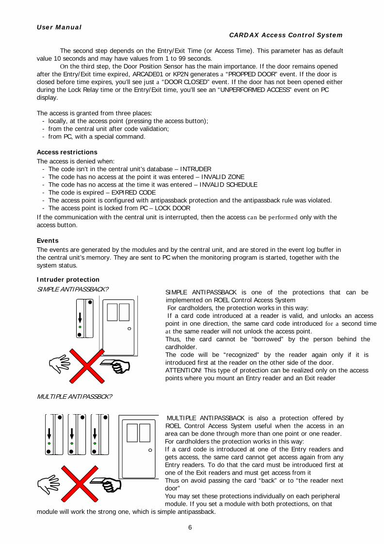
Intruder protection SIMPLE ANTIPASSBACK?
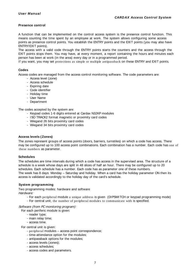
MULTIPLE ANTIPASSBCK?
MULTIPLE ANTIPASSBACK is also a protection offered by ROEL Control Access System useful when the access in an area can be done through more than one point or one reader. For cardholders the protection works in this way: If a card code is introduced at one of the Entry readers and gets access, the same card cannot get access again from any Entry readers. To do that the card must be introduced first at one of the Exit readers and must get access from it Thus on avoid passing the card “back” or to “the reader next door” You may set these protections individually on each peripheral module. If you set a module with both protections, on that
module will work the strong one, which is simple antipassback.
SIMPLE ANTIPASSBACK is one of the protections that can be implemented on ROEL Control Access System For cardholders, the protection works in this way: If a card code introduced at a reader is valid, and unlocks an access point in one direction, the same card code introduced for a second time at the same reader will not unlock the access point. Thus, the card cannot be “borrowed” by the person behind the cardholder. The code will be “recognized” by the reader again only if it is introduced first at the reader on the other side of the door. ATTENTION! This type of protection can be realized only on the access points where you mount an Entry reader and an Exit reader
User Manual CARDAX Access Control System
7
Presence control A function that can be implemented on the control access system is the presence control function. This means counting the time spent by an employee at work. The system allows configuring some access points as presence control points. You establish the ENTRY points and the EXIT points (you may also have ENTRY/EXIT points). The access with a valid code through the ENTRY points starts the counters and the access through the EXIT points stops them. You may have, at every moment, a report containing the hours and minutes each person has been at work (in the area) every day or in a programmed period. If you want, you may set protections as simple or multiple antipassback on these ENTRY and EXIT points. Codes Access codes are managed from the access control monitoring software. The code parameters are:
- Access level (zone) - Access schedule - Expiring date - Code identifier - Holiday time - User Name - Department
The codes accepted by the system are:
- Keypad codes 1-6 digits entered at Cardax N32KP modules - ISO TRACK2 format magnetic or proximity card codes - Wiegand 26 bits proximity card codes - Wiegand 34 bits proximity card codes
Access levels (Zones) The zones represent groups of access points (doors, barriers, turnstiles) on which a code has access. There may be configured up to 100 access point combinations. Each combination has a number. Each code has one of these numbers as parameter. Schedules The schedules are time intervals during which a code has access in the supervised area. The structure of a schedule is a week whose days are split in 48 slices of half an hour. There may be configured up to 20 schedules. Each schedule has a number. Each code has as parameter one of these numbers. The week has 8 days: Monday – Saturday and holiday. When a card has the holiday parameter ON then its access is validated accordingly to the holiday day of the card’s schedule. System programming Two programming modes: hardware and software Hardware:
- For each peripheral module a unique address is given (DIPSWITCH or keypad programming mode) - For central unit, the number of peripheral modules to communicate with is specified.
Software (from PC monitoring program): For each periferic module is given:
- reader type; - main relay time; - access time.
For central unit is given: - peripheral modules – access point correspondence; - time-attendance option for the modules; - antipassback options for the modules; - access levels (zones); - access schedules; - access codes and parameters.
User Manual CARDAX Access Control System
8
2. CARDAX COMPONNENTS
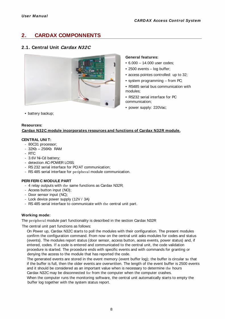
2.1. Central Unit Cardax N32C
General features: • 6.000 – 14.000 user codes;
• 2500 events – log buffer;
• access pointes controlled: up to 32;
• system programming – from PC;
• RS485 serial bus communication with modules;
• RS232 serial interface for PC communication; • power supply: 220Vac;
• battery backup;
Resources: Cardax N32C module incorporates resources and functions of Cardax N32R module. CENTRAL UNIT:
- 80C31 processor; - 32Kb – 256Kb RAM - RTC - 3.6V Ni-Cd battery; - detection AC-POWER LOSS; - RS 232 serial interface for PC/AT communication; - RS 485 serial interface for peripheral module communication.
PERIFERIC MODULE PART
- 4 relay outputs with the same functions as Cardax N32R; - Access button input (NO); - Door sensor input (NC); - Lock device power supply (12V / 3A) - RS 485 serial interface to communicate with the central unit part.
Working mode: The peripheral module part functionality is described in the section Cardax N32R The central unit part functions as follows:
On Power up, Cardax N32C starts to poll the modules with their configuration. The present modules confirm the configuration command. From now on the central unit asks modules for codes and status (events). The modules report status (door sensor, access button, acess events, power status) and, if entered, codes. If a code is entered and communicated to the central unit, the code validation procedure is started. The procedure ends with specific events and with commands for granting or denying the access to the module that has reported the code. The generated events are stored in the event memory (event buffer log); the buffer is circular so that if the buffer is full, then the older events are overwritten. The length of the event buffer is 2500 events and it should be considered as an important value when is necessary to determine the hours Cardax N32C may be disconnected for from the computer when the computer crashes. When the computer runs the monitoring software, the central unit automatically starts to empty the buffer log together with the system status report.
User Manual CARDAX Access Control System
9
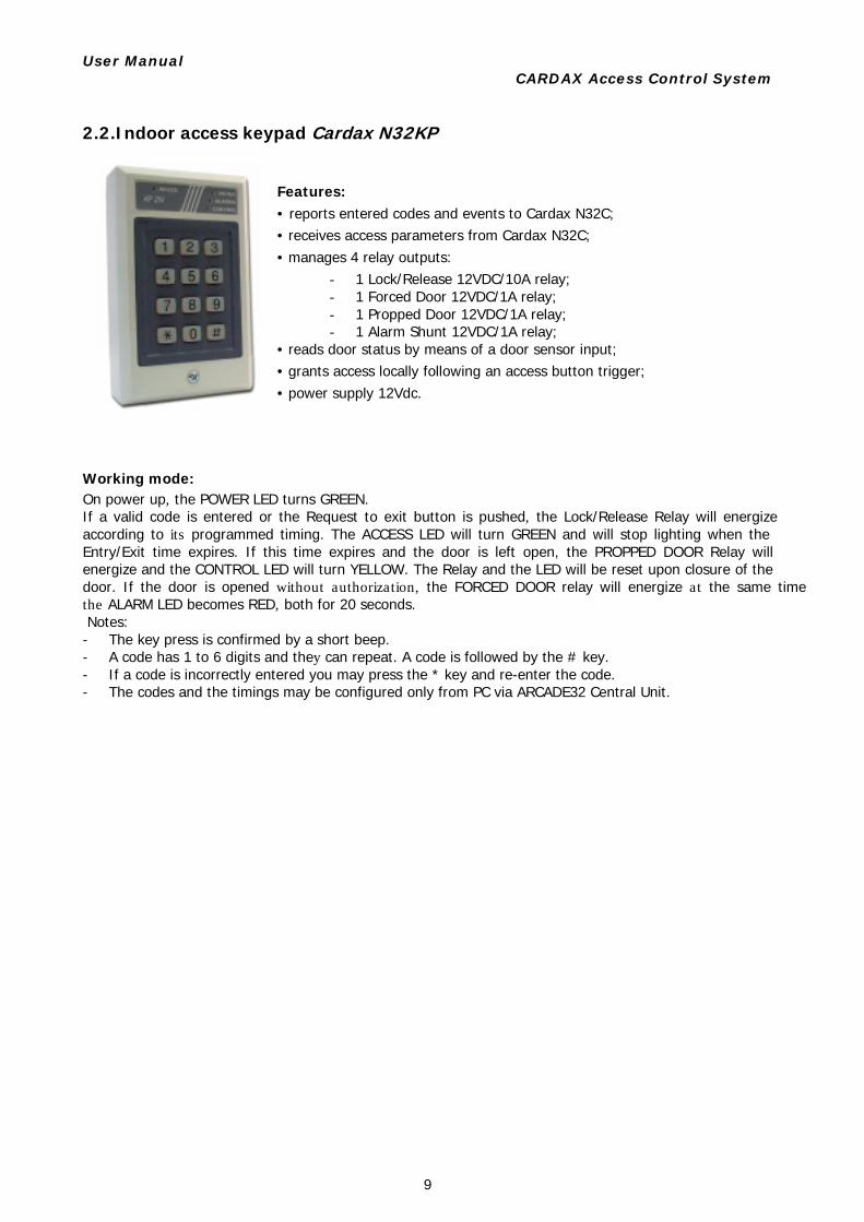
2.2.Indoor access keypad Cardax N32KP
Features: • reports entered codes and events to Cardax N32C; • receives access parameters from Cardax N32C; • manages 4 relay outputs:
- 1 Lock/Release 12VDC/10A relay; - 1 Forced Door 12VDC/1A relay; - 1 Propped Door 12VDC/1A relay; - 1 Alarm Shunt 12VDC/1A relay;
• reads door status by means of a door sensor input; • grants access locally following an access button trigger; • power supply 12Vdc.
Working mode: On power up, the POWER LED turns GREEN. If a valid code is entered or the Request to exit button is pushed, the Lock/Release Relay will energize according to its programmed timing. The ACCESS LED will turn GREEN and will stop lighting when the Entry/Exit time expires. If this time expires and the door is left open, the PROPPED DOOR Relay will energize and the CONTROL LED will turn YELLOW. The Relay and the LED will be reset upon closure of the door. If the door is opened without authorization, the FORCED DOOR relay will energize at the same timethe ALARM LED becomes RED, both for 20 seconds. Notes: - The key press is confirmed by a short beep. - A code has 1 to 6 digits and they can repeat. A code is followed by the # key. - If a code is incorrectly entered you may press the * key and re-enter the code. - The codes and the timings may be configured only from PC via ARCADE32 Central Unit.
User Manual CARDAX Access Control System
10
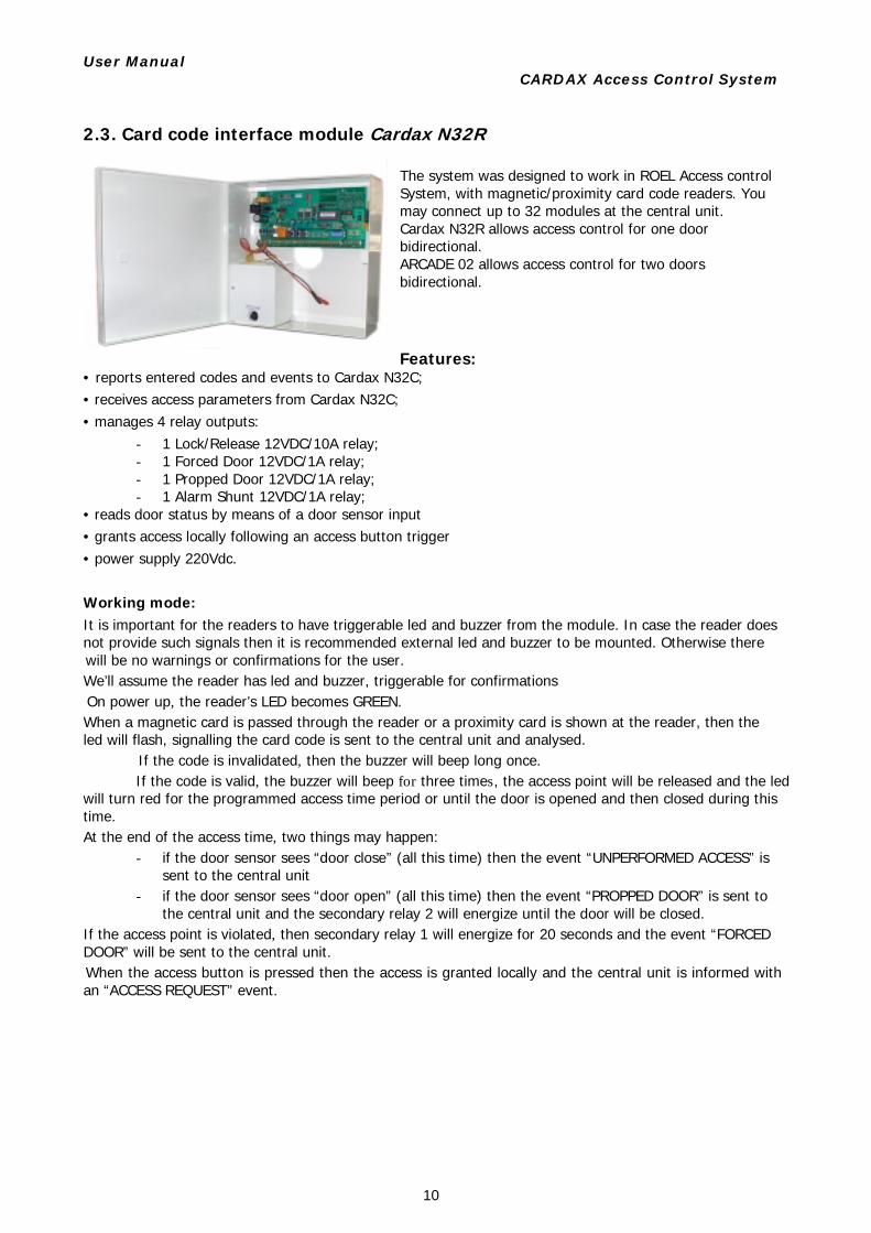
2.3. Card code interface module Cardax N32R The system was designed to work in ROEL Access control System, with magnetic/proximity card code readers. You may connect up to 32 modules at the central unit. Cardax N32R allows access control for one door bidirectional. ARCADE 02 allows access control for two doors bidirectional. Features:
• reports entered codes and events to Cardax N32C; • receives access parameters from Cardax N32C; • manages 4 relay outputs:
- 1 Lock/Release 12VDC/10A relay; - 1 Forced Door 12VDC/1A relay; - 1 Propped Door 12VDC/1A relay; - 1 Alarm Shunt 12VDC/1A relay;
• reads door status by means of a door sensor input • grants access locally following an access button trigger • power supply 220Vdc. Working mode: It is important for the readers to have triggerable led and buzzer from the module. In case the reader does not provide such signals then it is recommended external led and buzzer to be mounted. Otherwise there will be no warnings or confirmations for the user. We’ll assume the reader has led and buzzer, triggerable for confirmations On power up, the reader’s LED becomes GREEN. When a magnetic card is passed through the reader or a proximity card is shown at the reader, then the led will flash, signalling the card code is sent to the central unit and analysed.
If the code is invalidated, then the buzzer will beep long once.If the code is valid, the buzzer will beep for three times, the access point will be released and the led
will turn red for the programmed access time period or until the door is opened and then closed during this time. At the end of the access time, two things may happen:
- if the door sensor sees “door close” (all this time) then the event “UNPERFORMED ACCESS” is sent to the central unit
- if the door sensor sees “door open” (all this time) then the event “PROPPED DOOR” is sent to the central unit and the secondary relay 2 will energize until the door will be closed.
If the access point is violated, then secondary relay 1 will energize for 20 seconds and the event “FORCED DOOR” will be sent to the central unit. When the access button is pressed then the access is granted locally and the central unit is informed with an “ACCESS REQUEST” event.
User Manual CARDAX Access Control System
11
2.4. Monitoring software and Presence software The software package delivered with the system components contains three separate programs: The monitoring software used to configure the system, monitor and store access control events; The presence software use to generate time-attendance reports accordingly to the Romanian law and map editor software used to graphically generate a map of the supervised area.
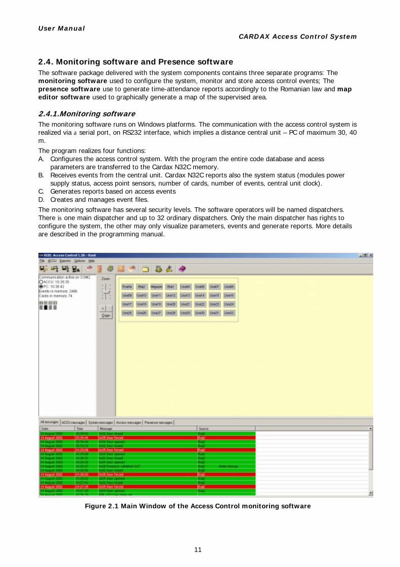
2.4.1.Monitoring software The monitoring software runs on Windows platforms. The communication with the access control system is realized via a serial port, on RS232 interface, which implies a distance central unit – PC of maximum 30, 40 m. The program realizes four functions: A. Configures the access control system. With the program the entire code database and acess
parameters are transferred to the Cardax N32C memory. B. Receives events from the central unit. Cardax N32C reports also the system status (modules power
supply status, access point sensors, number of cards, number of events, central unit clock). C. Generates reports based on access events D. Creates and manages event files. The monitoring software has several security levels. The software operators will be named dispatchers. There is one main dispatcher and up to 32 ordinary dispatchers. Only the main dispatcher has rights to configure the system, the other may only visualize parameters, events and generate reports. More details are described in the programming manual.
Figure 2.1 Main Window of the Access Control monitoring software
User Manual CARDAX Access Control System
12
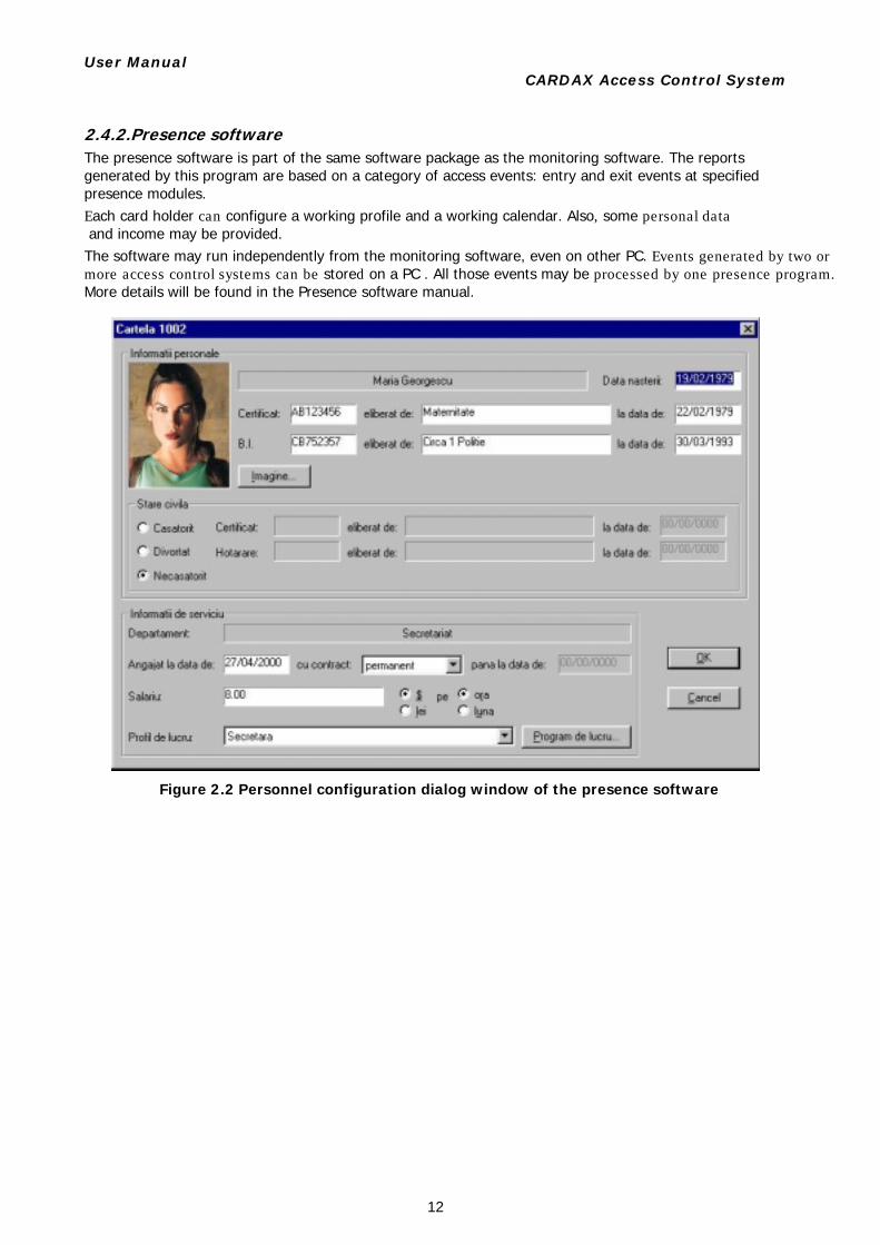
2.4.2.Presence software The presence software is part of the same software package as the monitoring software. The reports generated by this program are based on a category of access events: entry and exit events at specified presence modules. Each card holder can configure a working profile and a working calendar. Also, some personal data and income may be provided. The software may run independently from the monitoring software, even on other PC. Events generated by two ormore access control systems can be stored on a PC . All those events may be processed by one presence program.More details will be found in the Presence software manual.
Figure 2.2 Personnel configuration dialog window of the presence software
User Manual CARDAX Access Control System
13
3. USING CARDAX SYSTEM
There are two user categories of an access control system: the card holders, who have access rights, and the software operators, who monitor them.
3.1. Using the system: card holders The card holders interact with the code readers. The system provides alerts, warnings and confirmations, depending on the events issued at the access point and the user operations. Thus:
- Code entering is followed by opto-acoustic signals of code validation/invalidation and, implicitly, granting/denying access. The signals may differ from one reader type to another
- Events like „Forced door” or „Door propped” are also followed by relay triggers, usable for specific alert policies.
3.2. Using the system: dispatchers The dispatchers are involved in the programming process and monitoring process. Also, they may be asked to generate a report based on the events received from the system. More details are presented in the software manuals but we’ll give below some short specification on what could be done: First system programming
- First off all, the dispatcher should make sure that the communication between PC and system works perfectly and the computer runs the monitoring software.
At the first configuration, the steps are: - Erase event memory; - Erase code memory; - Configure access point names and building map; - Program module parameters; - Program access zones; - Program access schedules; - Configure access codes – please study the manual to learn about new code configuration. - Program code parameters - Transfer codes to central unit
Notes: 1. Any update in the PC database should be communicated to the central unit. 2. The access codes may not be programmed manually. They would rather be read from the code readers. 3. Any transfer of information to the central unit is confirmed. The response could be seen in the
message window.
Modifying configuration - The dispatcher should make sure that the communication between PC and system works perfectly and
the computer runs the monitoring software. - The main dispatcher will perform parameter changes. - The dispatcher should not forget to update the central unit with the new changes and should save the
new database on hard disk (Ctrl+S). Deleting system parameters
- The dispatcher should be assured that the communication between PC and system works perfectly and the computer runs the monitoring software.
- Erase code memory - Erase event memory
Monitoring the system The software displayes the events generated by the system in the message window on line. The changes of access point status will be reflected on the building map and in the status window.
User Manual CARDAX Access Control System
14
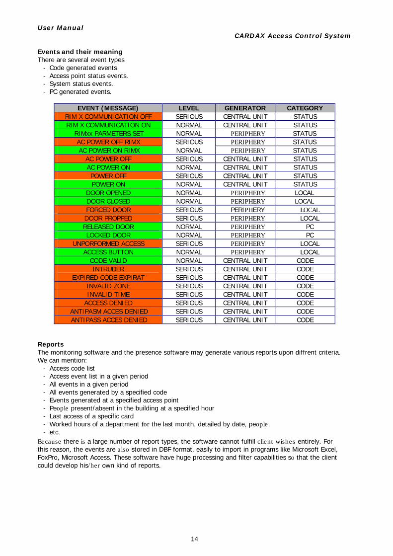
Events and their meaning There are several event types
- Code generated events - Access point status events. - System status events. - PC generated events.
EVENT (MESSAGE) LEVEL GENERATOR CATEGORY
RIM X COMMUNICATION OFF SERIOUS CENTRAL UNIT STATUS RIM X COMMUNICATION ON NORMAL CENTRAL UNIT STATUS
RIMxx PARMETERS SET NORMAL PERIPHERY STATUS AC POWER OFF RIMX SERIOUS PERIPHERY STATUS AC POWER ON RIMX NORMAL PERIPHERY STATUS
AC POWER OFF SERIOUS CENTRAL UNIT STATUS AC POWER ON NORMAL CENTRAL UNIT STATUS POWER OFF SERIOUS CENTRAL UNIT STATUS POWER ON NORMAL CENTRAL UNIT STATUS
DOOR OPENED NORMAL PERIPHERY LOCAL DOOR CLOSED NORMAL PERIPHERY LOCAL FORCED DOOR SERIOUS PERIPHERY LOCALDOOR PROPPED SERIOUS PERIPHERY LOCAL RELEASED DOOR NORMAL PERIPHERY PC LOCKED DOOR NORMAL PERIPHERY PC
UNPORFORMED ACCESS SERIOUS PERIPHERY LOCAL ACCESS BUTTON NORMAL PERIPHERY LOCAL
CODE VALID NORMAL CENTRAL UNIT CODE INTRUDER SERIOUS CENTRAL UNIT CODE
EXPIRED CODE EXPIRAT SERIOUS CENTRAL UNIT CODE INVALID ZONE SERIOUS CENTRAL UNIT CODE INVALID TIME SERIOUS CENTRAL UNIT CODE
ACCESS DENIED SERIOUS CENTRAL UNIT CODE ANTIPASM ACCES DENIED SERIOUS CENTRAL UNIT CODE ANTIPASS ACCES DENIED SERIOUS CENTRAL UNIT CODE
Reports The monitoring software and the presence software may generate various reports upon diffrent criteria. We can mention:
- Access code list - Access event list in a given period - All events in a given period - All events generated by a specified code - Events generated at a specified access point - People present/absent in the building at a specified hour - Last access of a specific card - Worked hours of a department for the last month, detailed by date, people. - etc.
Because there is a large number of report types, the software cannot fulfill client wishes entirely. For this reason, the events are also stored in DBF format, easily to import in programs like Microsoft Excel, FoxPro, Microsoft Access. These software have huge processing and filter capabilities so that the client could develop his/her own kind of reports.


![Cardax FT System Catalogue[1]](https://img.pdfslide.us/doc/110x75/55375f3255034634078b4caf/cardax-ft-system-catalogue1.jpg)