Embed Size (px)
Citation preview

Trak Engineering, Inc. 2901 Crescent Drive
Tallahassee, FL 32301-3535 Phone: 850-878-4585 Fax: 850-656-8265
Website: www.trakeng.com
SentryGOLD and Compact Assembly Manual 1
SentryGOLDAssembly Manual

Covered in this Manual:
SentryGOLD and the Compact
SentryGOLD COMPACT Dispenser for digital/electronic dispensers
SentryGOLD and Compact Assembly Manual 2
This SentryGOLD manual provides detailed instructions on how to build the Compact and the SentryGOLD COMPACT Dispenser models.
The SentryGOLD’s Compact is installed into the gold-colored pedestal and is placed on the fuel island adjacent to a fuel dispenser. It requires a Mother Board and Plug-in Cards.
The SentryGOLD COMPACT Dispenser works only with a digital (electronic) dispenser. It is installed directly into the face of a Bennett or Dresser-Wayne fuel dispenser. It does not require a Mother Board or Plug-In Card.

Revisi o ns to SentryGOLD Assembly
Revision October 2008 per John Blyth.add lock washer and extra standoffs to rod assembly
Revision November 2008 per John Blythall touch screens must be sealed with Plasti-DipNew touch screens pre gasketed received from vendor, this item is not longer applicable – Cheryl Gilman August 2010.
Revision November 2008 per John Blythhigher density foam to be used around display cut out on face plateall touch screens must be sealed with RTV not Plasti-Dip
Revision March 23, 2009 per John Blyth & Stuart Johnson ground wire to be added to back panel power supply. Tech (Joe Bowen) in field shocked multiple times while trying to install sentry head at Sumter Electric (SECO). Found that Sentry head needs to be grounded add hole to back panel so that the ground wire can exit through the back ofthe Sentry. Green 26 awg wire with 3 connectors, index numbers: #3172, 4351 & 4350
Revision April 01, 2009 per John Blyth & Stuart Johnsonadd battery to back of MCB add a nylon spacer (#5868) between the LCD Board and the MCB when installing to provide a sufficient gap and eliminate shorting out the battery.
SentryGOLD and Compact Assembly Manual 3

Table of Contents
PARTS LIST: ............................................................................................................................................... 1
SECTION 1 FACEPLATE ................................................................................................................... 3 1.1 INSTALL HEATER.................................................................................................................................. 3 1.2 INSTALL THREADED GOLD INSERTS .................................................................................................... 3 1.3 FOAM RUBBER ..................................................................................................................................... 4 1.4 THREADED RODS ................................................................................................................................. 4
SECTION 2 DISPLAY .......................................................................................................................... 6
2.1 PLACE TOUCH SCREEN ONTO DISPLAY ................................................................................................ 6
SECTION 3 SYSTEM ASSEMBLY .................................................................................................... 6
3.1 PLACE DISPLAY ONTO FACE PLATE .................................................................................................... 6 3.2 INSTALL LCD (CARRIER) INTERFACE BOARD...................................................................................... 7 3.3 INSTALL MASTER CONTROL BOARD (MCB)........................................................................................ 7 3.4 INSTALL SINGLE BOARD COMPUTER (SBC)......................................................................................... 7
SECTION 4 WIRING ........................................................................................................................... 8 4.1 INSERT 50 PIN CONNECTOR ................................................................................................................. 8
SECTION 5 HOUSING & BACK PLATE ......................................................................................... 8 5.1 COMPACT HOUSING INSTALLATION ..................................................................................................... 8 5.2 INSTALLING BACK PLATE .................................................................................................................... 8 5.3 SPEAKER PANEL .................................................................................................................................. 8
SECTION 6 SOFTWARE INSTALLATION .................................................................................... 9 6.1 SBC PARTITION – CREATING THE NANDFLASH FOLDER ................................................................ 9 6.4 SG4 SOFTWARE ............................................................................................................................... .10 6.5 AUTO RUN ................................................................................................................. ....................10 6.6 CUSTOMER SET-UP FILES ................................................................................................................11
Setup.txt .............................................................................................................................................. .11 1. Customer Number (system#) ................................................................................................................ 11 2. Sentry Number...................................................................................................................................... 11 3. Pump Time on ...................................................................................................................................... 11 4. Pump Time Off ..................................................................................................................................... 11 5. Baud Rate ............................................................................................................................................. 11 6. Mileage Retries..................................................................................................................................... 11 7. Mileage Window .................................................................................................................................. 11 8. PCCOMM Port ..................................................................................................................................... 11 9. Print Receipt ......................................................................................................................................... 12 10. Device type ........................................................................................................................................... 12 11. Logging ................................................................................................................................................ 12 12. Key Type .............................................................................................................................................. 12 13. Automation ........................................................................................................................................... 12
Screens.txt ............................................................................................................................... .............12 1. Order ID ............................................................................................................................................... 12 2. Screen Order ......................................................................................................................................... 13 3. Picture................................................................................................................................................... 13 4. Screen ID .............................................................................................................................................. 13 5. Data Entry Type ................................................................................................................................... 13 6. Timeout ................................................................................................................................................ 13 7. Minimum Length .................................................................................................................................. 13 8. Maximum Length ................................................................................................................................. 13
SentryGOLD and Compact Assembly Manual 4

9. Minimum Value.................................................................................................................................... 13 10. Maximum Value ................................................................................................................................... 13 11. Data Type ............................................................................................................................................. 13 12. Verify ................................................................................................................................................... 14 13. Data Attached ....................................................................................................................................... 14
Products.txt ......................................................................................................................................... .14 1. Product Number.................................................................................................................................... 14 2. Product Name ....................................................................................................................................... 14
Tanks.txt ............................................................................................................................................. .14 1. Tank Number........................................................................................................................................ 14 2. Product Number.................................................................................................................................... 14 3. Price Per Unit ....................................................................................................................................... 14
Pumps.txt ............................................................................................................................................ .14 1. Pump Number (sentry system pump # assigned) .................................................................................. 14 2. External Pump Number (dispenser hose #) .......................................................................................... 14 3. Tank Number........................................................................................................................................ 14
Prompts.txt .......................................................................................................................................... .15 1. Screen Order ......................................................................................................................................... 15 2. Prompt Number .................................................................................................................................... 15 3. Prompt String ....................................................................................................................................... 16 4. Sound String ......................................................................................................................................... 16
Sound Waves currently available ........................................................................................................18
SECTION 7 INITIAL TEST ...............................................................................................................19
SECTION 8 COMPACT DISPENSER MODEL TEST PROCEDURES .......................................22
SECTION 9 ASSEMBLY CHECKLIST ............................................................................................23
APPENDIX 1 .............................................................................................................................................. .24 PLACEMENT OF GOLD INSERTS INTO THE SENTRY GOLD & BENNETT FACEPLATES . .........................24
APPENDIX 2 .............................................................................................................................................. .25 FOAM PLACEMENT ................................................................................................................................... .25
APPENDIX 3 .............................................................................................................................................. .26 ASSEMBLED DISPLAY WITH SPACERS ........................................................................................................26
APPENDIX 4 .............................................................................................................................................. .27 LCD (CARRIER) INTERFACE BOARD .........................................................................................................27
APPENDIX 5 .............................................................................................................................................. .28 MCB PLACEMENT .....................................................................................................................................28
APPENDIX 6 .............................................................................................................................................. .29 SBC PLACEMENT ..................................................................................................................................... .29
APPENDIX 7 .............................................................................................................................................. .30 WIRING DIAGRAM .................................................................................................................................... .30
APPENDIX 8 .............................................................................................................................................. .31 BACK PLATE STICKER POSITIONING ..........................................................................................................31
APPENDIX 9 .............................................................................................................................................. .32 L‟IL BOB (GAS BOY DISPENSER CIRCUIT BOARD) ....................................................................................32
SentryGOLD and Compact Assembly Manual 5

Part # Description50271 LCD Interface Board 50251 Master Control Board (MCB) 5146 System Control Board (SBC) 50304 Back Plate AssemblyVarious Speaker Plate Assembly
- Heater 100 ohm (meter at 3.5 ohm maximum)- RTV - Propane Torch 14.1 oz
411 Mount wire (ABMM-A-C) 440 Nut 6-32 finger442 Nut 8-32 lock620 Screw 6-32 3/8” pan 100‟s630 Screw 8-32 3/8” pan 800 Washer #6 lock802 Washer #8 lock (internal tooth)803 Washer flat, nylon 814 Wire tie 4.0” 912 Nut nylon1087 Screw truss head ¼” 4-40 .1121383 Wire ties nylon 2.8 length .07” CS2606 Heat shrink clear 3-32 (32/box)3538 Heat shrink 3/8” black4014 Screw 2-56 5/8” Phillips machine 5206 Plug ½” finishing5338 Power supply 4” x 2”5343 Jam nut size 115386 Jam nut for CPC Connector5597 Insert thermoplastic 6-32 SG 5775 Display Optex T-51638D084J-FW-A-AB5782 Rod, threaded 18-8 SS 6-32 3‟ long 5783 Swage standoff 4-40 ½” w/swage F5784 Standoff ½” 2-56 male-female5788 Display 8.4A 2.9mm glass with rear ADH5795 Spacer ¼” long5863 Foam rubber, 1/8” x ½” ADH black5864 Foam rubber 1/8” x 3/8” ADH black 5868 Spacer ¼” OD 1/8” long #8 nylon5897 Fan Sunon 52-54 CFM 115V5911 Mesh sentry 7 & Bennett for fans5868 Nylon Washer 3320 Battery
SentryGOLD and Compact Assembly Manual 6
Parts List: Qty
1 1 1 1 1 1 - - 1 8 4 4 4 9 8 5 1 4 3 2
1 1 1 2 1 4 1 4 4 1 1 8
4 1 1 4 1
You will need the following Assemblies to fully complete a SentryGOLD unit:1. LCD Interface (Carrier) Board Assembly.
a. LCD Inverter Boards 2. Master Control Board. 3. Single Board Computer. 4. Back Plate Assembly. 5. Speaker Panel Assembly.
LCD Inverter Boards
LCD Interface (Carrier) Board Master Control Board (MCB)
Single Board Computer (SBC) Back Plate Assembly
Speaker Panel Assembly Heater Assembly
SentryGOLD and Compact Assembly Manual 7

Section 1 Faceplate
1.1- Install Heater Parts required: Face Plate Heater 4 x 100ohm Resistors, 1 tubing of RTV.
Place heater assembly into the slot located directly below the Display Panel Cut-Out
Heater Slot
The thermostat on heater is placed at the widestsection of the slot
Fill the heater slot with RTV; make sure it is flush with the faceplate to provide a flat surface for applying the foam rubber later on. Make sure that the ceramic resistors of theheater are not coming through the RTV they must be completely submerged.
RTV takes approximately 8 hrs to dry completely, so make sure to install the heater themoment you receive the face plate from the Machine Shop.
1.2- Install Threaded Gold InsertsPart number required: 5597, 6343
Place the inserts onto a rod or a few 6-32 1”screws, anything that will create a handle to hold the insert over the torch flame.
Note: It is very important that the inserts are setstraight and is flush with the faceplate.
Heat the insert with the torch for approximately 10-12 seconds. Place the heated insert into the hole on the faceplate pressing slowly and lightly down to set it into the plastic. Complete all of theother inserts in this manner.
SentryGOLD and Compact Assembly Manual 8

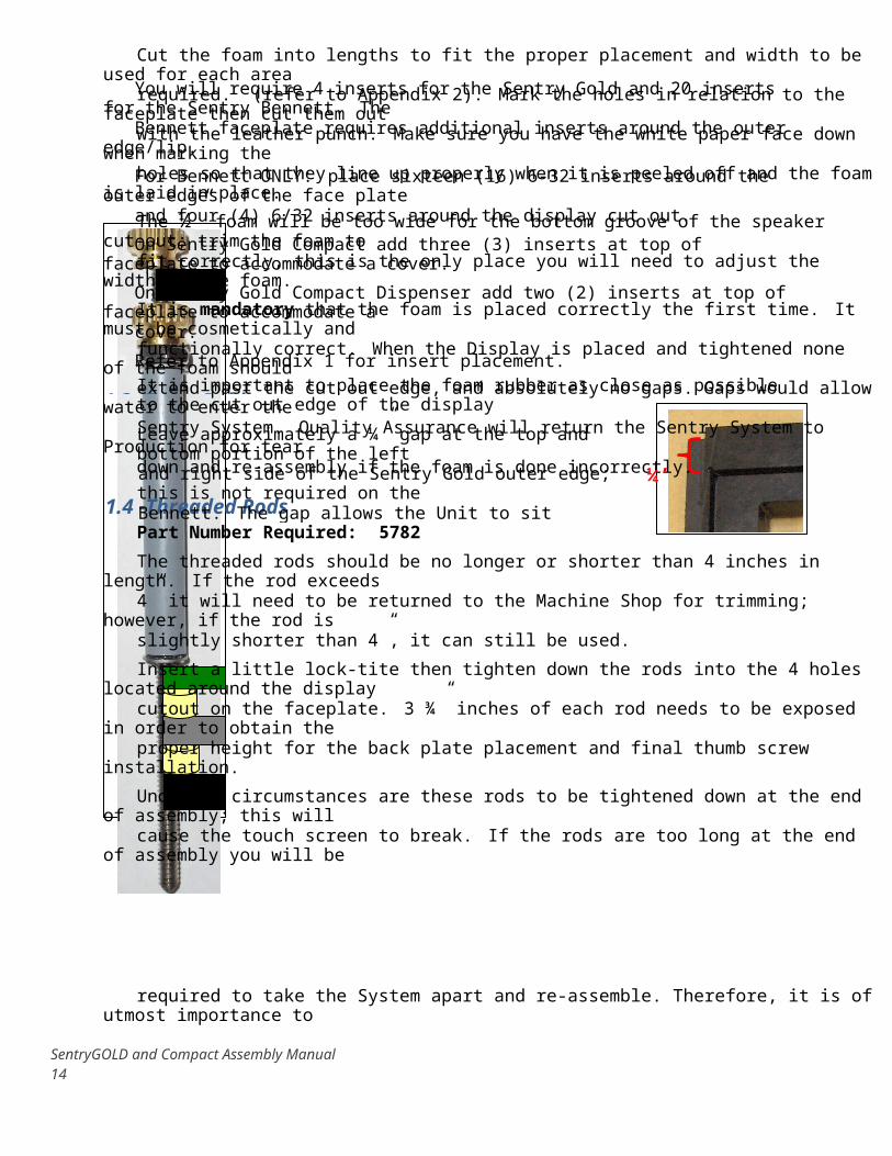
Cut the foam into lengths to fit the proper placement and width to be used for each area required. (refer to Appendix 2). Mark the holes in relation to the faceplate then cut them outwith the leather punch. Make sure you have the white paper face down when marking the holes so that they line up properly when it is peeled off and the foam is laid in place.
The ½” foam will be too wide for the bottom groove of the speaker cut-out; trim the foam to fit correctly, this is the only place you will need to adjust the width of the foam.
It is mandatory that the foam is placed correctly the first time. It must be cosmetically andfunctionally correct. When the Display is placed and tightened none of the foam should extend past the cut out edge, and absolutely no gaps. Gaps would allow water to enter the Sentry System. Quality Assurance will return the Sentry System to Production for tear down and re-assembly if the foam is done incorrectly.
1.4 -Threaded Rods Part Number Required: 5782
The threaded rods should be no longer or shorter than 4 inches in length. If the rod exceeds4” it will need to be returned to the Machine Shop for trimming; however, if the rod is slightly shorter than 4”, it can still be used.
Insert a little lock-tite then tighten down the rods into the 4 holes located around the display cutout on the faceplate. 3 ¾” inches of each rod needs to be exposed in order to obtain the proper height for the back plate placement and final thumb screw installation.
Under no circumstances are these rods to be tightened down at the end of assembly; this will cause the touch screen to break. If the rods are too long at the end of assembly you will be
SentryGOLD and Compact Assembly Manual 9
You will require 4 inserts for the Sentry Gold and 20 inserts for the Sentry Bennett. TheBennett faceplate requires additional inserts around the outer edge/lip.
For Bennett ONLY: place sixteen (16) 6-32 inserts around the outer edges of the face plateand four (4) 6/32 inserts around the display cut out.
On Sentry Gold Compact add three (3) inserts at top of faceplate to accommodate a cover.
On Sentry Gold Compact Dispenser add two (2) inserts at top of faceplate to accommodate acover.
Refer to Appendix 1 for insert placement.
1.3 -Foam Rubber Part number required: 5863, 5864
It is important to place the foam rubber as close as possible to the cut out edge of the display to eliminate water from getting through.
Leave approximately a ¼” gap at the top and bottom portion of the left and right side of the Sentry Gold outer edge; this is not required on theBennett. The gap allows the Unit to sit properly in the pedestal. All corners where the foam meets must be cut and fit correctly. Gaps or overlapping foam are not acceptable.
¼’

required to take the System apart and re-assemble. Therefore, it is of utmost importance to measure everything with a ruler, eyeballing it is not acceptable.
Sentry Gold/Compact Upgrade Released October 2008 by J. BlythRod assembly is as follows:
- 6-32 Thumbscrew - 6-32 Lock Washer- Back Panel
- 6-32 Thumbscrew
- 6-32 Nut - 6-32 Lock Washer
- Grey Standoff
- 6-32 Lock Washer - LCD Carrier Board- Standoff- Display with touch screen assembly- Standoff
- Faceplate
SentryGOLD and Compact Assembly Manual 10

Section 2 Display
2.1 -Place Touch Screen onto DisplayPart Number Required: 5788, 5775
Place the display on the table in front of you ready to add on the touch screen. Make sure thepink and white wires are on the opposite side of the yellow ribbon. Remove the protective film and do not touch the display. If you do accidentally touch the screen, you must clean it before placing the touch screen onto it. Be careful of lint or debris when cleaning with a cloth.
Carefully remove the adhesive sheet from the back of the touch screen. The gold ribbon should be to the opposite side of the pink and white wires. Center the touch screen with the display, the gold border around the touch screen should be lined up with the interior portion of the silver border of the display screen. If this is not the case, the gold border will be visible once placed into the faceplate and will not pass inspection. Make certain it is lined up correctly.
DO NOT push down on the touch screen until you are confident that it is placed correctly onto the display.
Seal with RTV around outer edge of touch screen. The sealant should be halfway throughthe gold trim on the touch screen, then on down to the display.
Clean the touch screen with a Windex sheet and let dry, then use a soft nonabrasive cloth tobuff and remove any streaks left from the Windex sheet.
Section 3 System Assembly
3.1 - Place Display onto Face PlatePart Number Required: 5795
Position the display screen over the four rods, line up holes then gently and carefully slide the display down the rods. The pink and white wires should be to the left of the face plate and the gold ribbon should be to the right of the face plate.
Sliding the display down the rods will be extremely difficult if the rods are crooked due to theincorrect setting of the gold inserts. Keep the display level while sliding it down. The machine shop will machine the holes in the display with a 5/32nd drill bit, if this has not been done see your Production Manager to have the holes enlarged.
Keep sliding the display down until the touch screen is sitting snug on the foam around the display cut out. Make sure that the display is sitting level. Tape the yellow ribbon with electrical tape to the back of the display to eliminate pinching when adding the housing.
NEVER bang or hit the display screen with anything to slide it down the rods.
Ask the Quality Inspector to review the partially assembled system(s), he/she will check for any errors before continuing with assembly.
SentryGOLD and Compact Assembly Manual 11

Once the System has passed inspection, place 1 standoff on each of the rods, refer to Appendix 3.
3.2 -Install LCD (Carrier) Interface BoardPart Number Required: 5795, 800, 440
Slide the LCD Board down the rods carefully, do not damage the board; if you do not push itdown slowly and evenly it will get stuck. Take your time and do it properly.
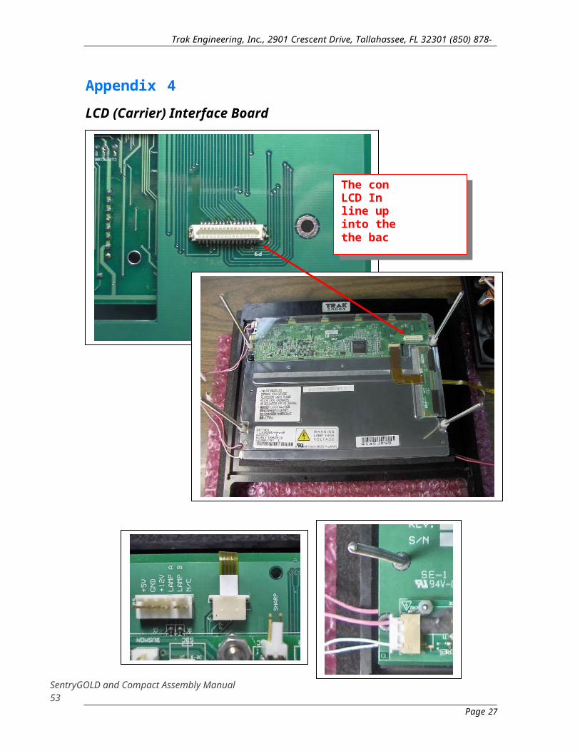
The inverters should be to the left side of the face plate; this is where the pink and whitewires will be plugged into, refer to Appendix 4
There is a white connector on the LCD board that needs to be plugged into the back of the display. Make sure they are plugged in before continuing. Make sure that the yellow ribbonis pulled out on the right side, do not fold it or crimp it.
Plug in the yellow ribbon from the Touch Screen into the LCD Ribbon connector and thepink and white wires from the back of the Display into the LCD Interface Board Inverter Board connections.
Place one 6-32 lock washer onto each rod.
Place one large grey spacer onto each rod.
Place one 6-32 lock washer onto each rod.
Place one 6-32 nut onto each rod. Do not tighten it too much or it will bow the LCD Board and will cause the connector between the LCD and Display to come apart.
Add one 6-332 thumb screw onto each rod. Screw down each thumbscrew until it fitssnugly on top of the nut.
3.3- Install Master Control Board (MCB)Part Number Required 2663, 439, 5868
Make sure that the MCB has a battery installed, refer to Appendix 5
Place a nylon spacer (#5868) on each of the five screws – per revision by John Blyth.
Place the MCB onto the 5 screws located on the LCD Board, refer to Appendix 5.
Secure the MCB in place with nylon washers and metal nuts on the four corner screws, the5th screw located on the side closest to the SBC does not require a washer or nut; it is not used to keep the MCB secure.
3.4 -Install Single Board Computer (SBC)Part Number Required 1087, 800
Place the SBC onto the 3 standoffs on LCD Board, refer to Appendix 6.
Secure the SBC in place with 3 screws and 3 lock washers.
Place a 2-56 3/4” screw with a small nylon washer into the grey ribbon connector board. The screw is used to prevent the ribbon cable from coming loose; it does not have to be extremely tight. Make sure not to tighten it so much that the nylon washer stretches and it
SentryGOLD and Compact Assembly Manual 12

pops out from under the screw and will cause the ribbon board to bow creating a badconnection.
Section 4 Wiring
4.1- Insert 50 Pin ConnectorPart Number Required: 5783, 5784, 4014, 803
Place the 50 pin connector onto the SBC board.
Connect all wiring from the Back Plate to the necessary positions on the Master Control Board and the SBC.
Refer to Appendix 7 for a wiring diagram.
Section 5 Housing & Back Plate
5.1 - Compact Housing InstallationCarefully place the housing (box) into the groove around the display cut out on theFaceplate.
Be very careful not to pinch any wires when placing the housing in position and pushing it into the groove.
The air holes in the housing should be positioned towards the bottom of the Unit and closest to the Face Plate. The hole on the side lines up with the USB Port on the SBC.
5.2 - Installing Back PlatePart Number Required: 440, 802
Place the back plate onto the four rods, it should fit snug into the housing.
It is important not to pinch any wires.
Once the back is properly in place the portion of rods above the back plate should not exceed 1/2”. Give the Unit a light shake and listen for any indication that some small parts may have fallen into it; this could cause a short when the Unit is powered up. Once you aresatisfied that you have completed everything you can place a lock washer on each of the rods followed by a thumbnut.
Place the stickers onto the back plate before sending unit to inspection or test. These stickers may have already been applied when the back panel was built and tested.
Refer to Appendix 8 for sticker positions.
5.3 - Speaker PanelA speaker panel has many options, it can consist of a Card Reader, Key Reader or both, andthese are just a few. Check the tag provided by the Production Manager for the options that the Customer selected. The tag will indicate what speaker panel is to be installed
SentryGOLD and Compact Assembly Manual 13
Position the speaker panel into the cut out; make sure the foam is on the faceplate, this should have been done when the faceplate was originally prepared.
Secure the speaker panel with ten 4-40 7/8” screws and ten 4-40 washers. Be careful when tightening down the screws, if you tighten them down too much it will dimple the front faceof the speaker panel.
A screw must be placed in the center bottom grooved portion of the face plate; it is required when the unit is placed in its pedestal at the installation site. This is only required on the SentryGold units.
Section 6 Software InstallationYou will require the USB Keyboard and the USB Key containing the latest released version of the SG4 software. If this system is reserved for a specific customer you will also need the customer specific set-up files from the Engineering or IT Department.
6.1 - SBC Partition – Creating the NANDFLASH FolderPlug in the Unit, it will boot up to a Windows screen, plug in the USB Keyboard. Note that the Unit will reboot after 2 minutes whether you have completed the following tasks or not so take a minute to review the steps before starting. Rushing will only create errors so take the necessary time needed to do it right the first time!
Open My Computer.
Open Control Panel.
Open Storage Manager.
Select New.
Input “NANDFLASH” in the text box area of the pop-up window.
Press “Enter” on the keyboard (or Select “OK” from the screen).
Select “Properties” (located at the lower right of the pop-up panel, *do not ever use the buttons on the left side*).
This will open a new pop-up window.
Select “Dismount” from the pop-up window.
Select “Format”
Select “Start”
Select “OK”
Select “Mount”
Select “OK”
Close all of the pop-ups by selecting “OK” at the top right of each pop-up.
Remove the USB Keyboard.
Allow the Unit to re-boot itself.
SentryGOLD and Compact Assembly Manual 14

6.4 - SG4 SoftwareSet Windows time to “(GMT) – Greenwich Mean Time: Dublin…”
The Unit will re-boot to the Windows screen. Again; note that the Unit will reboot after 2 minutes whether you have completed the following tasks or not so take a minute to review the steps before starting. Rushing will only create errors so take the necessary time neededto do it right the first time!
Insert the USB Key.
Open My Computer.
Open Hard Disk.
Select and Copy the SG4 Folder.
Return to My Computer.
Open the NandFlash Folder.
Paste the SG4 Folder.
Remove the USB Key.
Open the SG4 Folder.
Select and run the SG4 or Bootstrap executable file. Either one of the executable files can be run with the same results.
The Windows screen will remain but at the bottom on the Status Bar you should see a Blank Button. By pressing this button you will open the red/customer screen. You can also get to the red/customer screens by closing the Windows program.
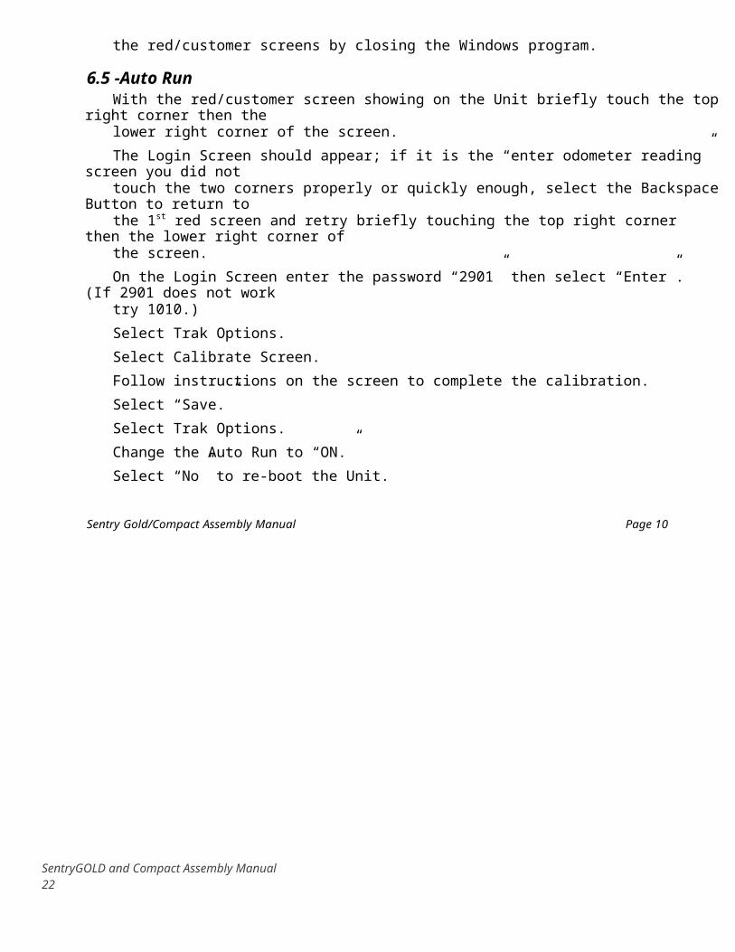
6.5 -Auto RunWith the red/customer screen showing on the Unit briefly touch the top right corner then the lower right corner of the screen.
The Login Screen should appear; if it is the “enter odometer reading” screen you did not touch the two corners properly or quickly enough, select the Backspace Button to return to the 1st red screen and retry briefly touching the top right corner then the lower right corner ofthe screen.
On the Login Screen enter the password “2901” then select “Enter”. (If 2901 does not worktry 1010.)
Select Trak Options.
Select Calibrate Screen.
Follow instructions on the screen to complete the calibration.
Select “Save.”
Select Trak Options.
Change the Auto Run to “ON.”
Select “No” to re-boot the Unit.
Sentry Gold/Compact Assembly Manual Page 10
SentryGOLD and Compact Assembly Manual 15
Trak Engineering, Inc., 2901 Crescent Drive, Tallahassee, FL 32301 (850) 878-4585
Select “Close.”
Select “Import Updates…”
Select “Yes.”
The Unit should boot up directly to the red screen.
All generic software has been loaded; eventually the customer software must be added. The Customer Set-Up files will be provided by the Engineering or IT Department.
6.6 Customer Set-Up FilesThe set-up files are provided by either the Engineering or IT Department and should be complete and correct. The following information for set-up files is provided to aid with troubleshooting if required. Do not attempt to change any of the coma delimited files (.txt) yourself. These .txt set-up files cannot be viewed on the Sentry System you will need to load them onto a computer and open them with notepad. Some examples are provided at the end of Section 7.
Setup.txt This setup file contains information that pertains to the entire sentry; there should only be one line in this file.
1. Customer Number (system#) 4 digits
2. Sentry Number3 digits
3. Pump Time on In seconds
4. Pump Time OffIn seconds
5. Baud Rate Any standard baud rate
6. Mileage Retries 3, same as Sentry 6
7. Mileage Window1000, same as Sentry 6
8. PCCOMM PortPort 1 or 3, whichever we are using to poll, 3 is the standard
SentryGOLD and Compact Assembly Manual 16

Sentry Gold/Compact Assembly Manual Page 11
SentryGOLD and Compact Assembly Manual 17

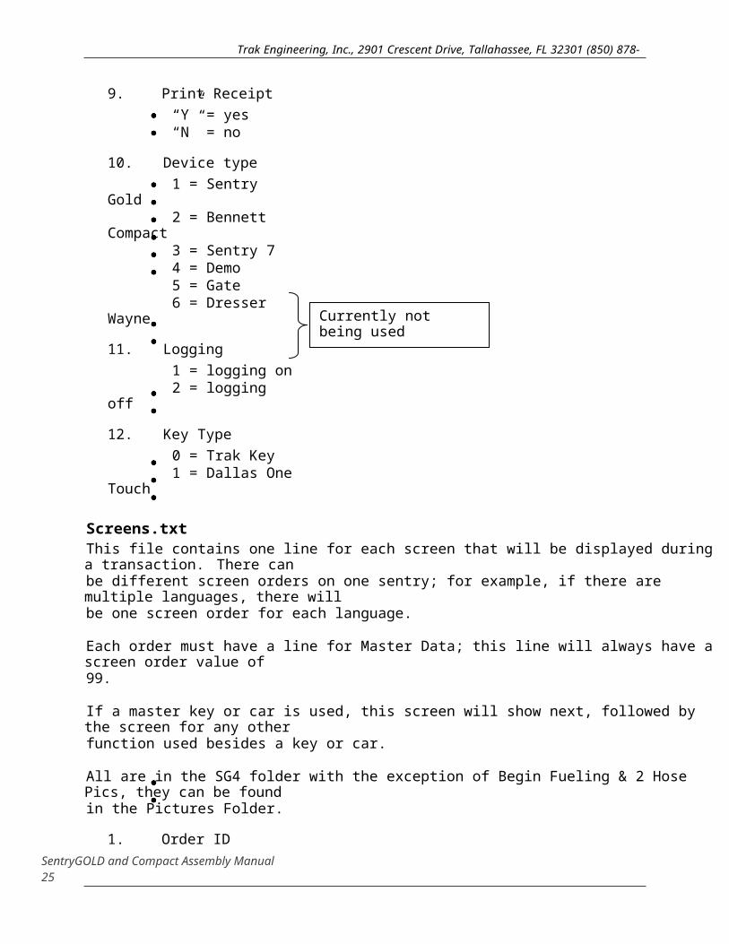
Screens.txtThis file contains one line for each screen that will be displayed during a transaction. There canbe different screen orders on one sentry; for example, if there are multiple languages, there will be one screen order for each language.
Each order must have a line for Master Data; this line will always have a screen order value of 99.
If a master key or car is used, this screen will show next, followed by the screen for any otherfunction used besides a key or car.
All are in the SG4 folder with the exception of Begin Fueling & 2 Hose Pics, they can be found in the Pictures Folder.
1. Order ID1 = English 2 = Spanish
SentryGOLD and Compact Assembly Manual 18
Trak Engineering, Inc., 2901 Crescent Drive, Tallahassee, FL 32301 (850) 878-4585
9. Print Receipt“Y” = yes“N” = no
10. Device type1 = Sentry Gold 2 = Bennett Compact3 = Sentry 74 = Demo5 = Gate 6 = Dresser Wayne
11. Logging1 = logging on 2 = logging off
12. Key Type0 = Trak Key 1 = Dallas One
Touch
13. Automation 0 = manual1 = partial
Currently not being used April 21, 2008
Sentry Gold/Compact Assembly Manual Page 12
SentryGOLD and Compact Assembly Manual 19

Trak Engineering, Inc., 2901 Crescent Drive, Tallahassee, FL 32301 (850) 878-4585
2. Screen OrderOrder of this screen in the current screen order
3. Picture What picture, if any will be displayed on the screen.
4. Screen ID What screen type this is, which currently consists of the following:
1) Key Pad Screen 2) Card Screen 3) Pump Screen 6) Key Read Screen
5. Data Entry Type1 = digits only2 = alphanumeric (keypad only)
6. TimeoutIn seconds, how long will the screen stay up without input
7. Minimum LengthShortest input length (keypad only)
8. Maximum LengthLongest input value (keypad only)
9. Minimum ValueLowest numeric value (keypad only)
10. Maximum ValueHighest numeric value allowed (keypad only)
11. Data Type 1 = MILEAGE2 = VEHICLE 3 = PERSONNEL 4 = CARD 5 = KEYDATA6 = TXTN7 = SETUP 8 = PUMP 9 = SCREEN10 = TXTNNEW11 = PRODUCT
SentryGOLD and Compact Assembly Manual 20

Sentry Gold/Compact Assembly Manual Page 13
SentryGOLD and Compact Assembly Manual 21
Trak Engineering, Inc., 2901 Crescent Drive, Tallahassee, FL 32301 (850) 878-4585
12 = KEYLOCK13 = OPTION114 = OPTION215 = OPTION316 = PROMPT17 = TANK
*NOTE: not all of these types can be used with screens, for example, keypad screens can beused for mileage, vehicle, personnel, and the option fields.
12. Verify Is the input checked against the data base associated with the data type indicated in field 11? 1 = yes0 = noWhat it reads against is on key and it writes back then
13. Data AttachedAre we just looking up the identity, or are we returning associated data? How – Doug thinks always zero for new.
Products.txt A list of products used by this sentry
1. Product Number2. Product Name
Tanks.txtA list of what tanks we are attached to, the products that are in them and the current fuel price inthat tank.
1. Tank Number2. Product Number3. Price Per Unit
Pumps.txtA list of what tank each pump is attached to, and what pump it is mapped to externally. For example, if this sentry is controlling pumps 3 & 4, pump 1 would be mapped to 3, and pump 2 would be mapped to 4.
1. Pump Number (sentry system pump # assigned) 2. External Pump Number (dispenser hose #)3. Tank Number
SentryGOLD and Compact Assembly Manual 22

Sentry Gold/Compact Assembly Manual Page 14
SentryGOLD and Compact Assembly Manual 23

Trak Engineering, Inc., 2901 Crescent Drive, Tallahassee, FL 32301 (850) 878-4585
Prompts.txtThere are many prompts used in a sentry, and each can be customized. Each prompt can also have an associated sound file. To customize a prompt, you need to know its number, and create a line in the prompts.txt file.
1. Screen OrderThe prompt can be different for each screen order.
2. Prompt NumberEach prompt has an associated constant number listed below.
o 0 = WELCOME o 1 = INCORRCT_LENGTH o 2 = DATA_MUST_BE_NUMBER o 3 = BAD_ODOMETER o 4 = VEHICLE_NOT_FOUND o 5 = PERSONNEL_NOT_FOUND o 6 = OPTION1_NOT_FOUND o 7 = OPTION2_NOT_FOUND o 8 = OPTION3_NOT_FOUND o 9 = INCORRECT_KEY_TYPE o 10 = KEY_LOCKED_OUT o 11 = BAD_KEY_READ o 12 = KEY_EXPIRED o 13 = BAD_CARD_TYPE o 14 = CARD_EXPIRED o 15 = CARD_LOCKED_OUT o 16 = CARD_NOT_FOUND o 17 = BAD_ACCOUNT_NUMBER o 18 = ENTER_ODOMETER o 19 = ENTER_VEHICLE_NUMBER o 20 = ENTER_PERSONNEL_NUMBER o 21 = ENTER_OPTION1 o 22 = ENTER_OPTION2 o 23 = ENTER_OPTION3 o 24 = INSERT_PERSONNEL_KEY o 25 = INSERT_VEHICLE_KEY o 26 = INSERT_CARD o 27 = SELECT_HOSE o 28 = KEY_READ_CORRECTLY o 29 = KEY_NOT_WRITTEN o 30 = CARD_READ_CORRECTLY o 31 = BEGIN_FUELING o 32 = INCORRECT_SYSTEM_NUMBER o 33 = REMOVE_CARD o 34 = BAD_CARD_READ o 35 = LIFT_LEVER (52.WAV)
SentryGOLD and Compact Assembly Manual 24
Sentry Gold/Compact Assembly Manual Page 15
SentryGOLD and Compact Assembly Manual 25

Trak Engineering, Inc., 2901 Crescent Drive, Tallahassee, FL 32301 (850) 878-4585
3. Prompt StringWhat the prompt should say
4. Sound String Name of the associated sound file, if any. If there is no sound file, put “.
For example, to make OPTION1_NOT_FOUND say COST CENTER NOT FOUND in the first screen order and COSTO CENTRO NOT FOUNDO in the second screen order, you would add two lines as follows:
1,5,‟COST CENTER NOT FOUND‟,”2,5,‟COSTO CENTRO NOT FOUNDO‟,”
If you have recorded wave files for each, and called them CC.WAV and CC_SPAN.WAV, youwould add them as follows:
1,5, „COST CENTER NOT FOUND‟, „CC.WAV‟ 2,3, „COSTO CENTRO NOT FOUNDO‟, „CC_SPAN.WAV‟
SentryGOLD and Compact Assembly Manual 26
EXAMPLES:
Page 16

Trak Engineering, Inc., 2901 Crescent Drive, Tallahassee, FL 32301 (850) 878-4585
SentryGOLD and Compact Assembly Manual 27

Sentry Gold/Compact Assembly Manual Page 17
SentryGOLD and Compact Assembly Manual 28

Welcome, press anywhere on the screen to beginPlease enter your odometer reading without 10th's and then press the nextbutton. Please insert keyPlease insert your fuel key Key was read correctly Please insert your fleet cardCard was read correctlyInsert your card as shown in the picturePlease insert your cardPlease remove your card Please enter your personnel ID Please select hose, the available hoses are green in color Thank you, you may begin fueling Thank your receipt is printing Thank you please take your receiptPlease enter your vehicle ID numberPlease enter your personnel ID numberVehicle number acceptedPersonnel number acceptedHose not available, please select another hose Access denied, please contact supervisor Touch your button key to the reader, as shown in the pictureKey okay Card okay Please enter the vehicle IDPlease allow Sentry to close Sentry is closing Please reinsert your key Incorrect mileagePlease reenter your cardLift the reset lever to start pump
Scan ID card as shown on the screen Lift the reset lever to start pump Lift the reset lever to start pumpLift the reset lever to start pump Lift the reset lever to start pump Enter your meter reading and then press the next button Enter your meter reading and then press the next button Enter your personnel number and the last four digits of your social security number Enter your personnel number and the last four digits of your social security number
SentryGOLD and Compact Assembly Manual 29
1.wav 2.wav
3.wav 4.wav 5.wav 6.wav 7.wav 8.wav 9.wav 10.wav 11.wav 12.wav 13.wav 14.wav 15.wav 16.wav 17.wav 18.wav 19.wav 20.wav 21.wav 22.wav 23.wav 24.wav 25.wav 26.wav 27.wav 28.wav 29.wav 30.wav 31.wav 32.wav 33.wav 34.wav 35.wav junk1.wav junk2.wav level1.wav lever2.wav meter1.wavmeter2.wavnumber1.wav
number2.wav
Trak Engineering, Inc., 2901 Crescent Drive, Tallahassee, FL 32301 (850) 878-4585
Sound Waves currently available:Sound Files: (111005)
Sentry Gold/Compact Assembly Manual Page 18

Trak Engineering, Inc., 2901 Crescent Drive, Tallahassee, FL 32301 (850) 878-4585
Section 7 Initial TestEach system should be put through an initial test in the production department.
Hook the sentry to the test computer via the spy cable. The spy cable is connected tothe computer with a DB9 cable at one end and a 2 pin connector at the other. The 2 pin connector plugs into the short 2 pin Molex located on the exterior comm. harness.
Power up system, it should boot up to the customer/generic welcome screen. Enter the override mode by touching the top and bottom right corners. This should bring you to a Login Screen.
Welcome Screen, select two corners Enter Login# 2901, select “Next”
Select TRAK Options Select Calibrate Touch Screen
* Note: Follow instructions on screen for calibration of touch screen. Save and Exit.
Override Screen, Select Configure Cards Query Screen
SentryGOLD and Compact Assembly Manual 30

Sentry Gold/Compact Assembly Manual Page 19
SentryGOLD and Compact Assembly Manual 31

Trak Engineering, Inc., 2901 Crescent Drive, Tallahassee, FL 32301 (850) 878-4585
All cards plugged into the mother board should be listed once the Query has completed.
This completes the Configure Cards testing.
Select “Exit” to return to Override Screen.
Override Screen, Select TRAK Options Select Detect Converter
The Detect Converter button text should change to “PORT 3” if it displays “NoneDetected” there is a communication error.Ensure your RS232 cable is plugged in correctly to the mother board.
It needs to read “PORT 3” to pass this test.
Verify Button says “Port 3”
If the Data Converter was detected on Port3, select the ComTest button.
SentryGOLD and Compact Assembly Manual 32

Sentry Gold/Compact Assembly Manual Page 20
SentryGOLD and Compact Assembly Manual 33
PORT:

Trak Engineering, Inc., 2901 Crescent Drive, Tallahassee, FL 32301 (850) 878-4585
Use pull down menu and change from AUX to LOCAL.
Make sure the Baud Rate is set to 9600.
Select Begin Test button
The second text area should be a replica of the first test area. This indicates that the system communicated fully with the Data Converter.
Communication test completed.
Select “Exit”, Select “Cancel.”
Override Screen.
Select Test Pumps.
Make sure you have a FOTX (Fiber Optic Transmit Card) installed in the Mother Board.
Select #1 button; this should turn on pump 1. It will be indicated on the FOTX card plugged into the Mother Board. Pump 1 LED should be lit.
Select #2 button; this should turn on pump 2. It will be indicated on the FOTX card plugged into the Mother Board. Pump 2 LED should be lit.
SentryGOLD and Compact Assembly Manual 34

Sentry Gold/Compact Assembly Manual Page 21
SentryGOLD and Compact Assembly Manual 35

Trak Engineering, Inc., 2901 Crescent Drive, Tallahassee, FL 32301 (850) 878-4585
Only test pumps one and two to ensure that they turn on. The generic software doesnot have pumps 3 through 12, if you select one of these pumps you will receive an SG4 error and have to reboot the system. The Quality Department will perform more intensive tests on the pumps, we are only concerned at this point that they turn on.
Return to the Override Screen.
Select Set Date/Time.
Set Date and Time, Save, Exit.
If all of the above tests pass place the system on the burn shelf. Make sure that allpaperwork is complete, place paperwork in file and give it to the Production Manager.
If any of the above tests fail give the system to the Quality Inspector, Mark White. Make sure to place a rework label onto the system and be descriptive so the Quality Inspector knows where to start the troubleshooting.
Section 8 Compact Dispenser Model Test ProceduresPower up L‟il Bob
Plug the Bus485 from Bob into the External Comm Harness Bus 485 connector
Access the Login screen
Enter Login# 2901 or 1010 – whichever is applicable to this Sentry, select “Next”
From the Main Option Screen and select Auto Detect Hoses
SentryGOLD and Compact Assembly Manual 36

Sentry Gold/Compact Assembly Manual Page 22
SentryGOLD and Compact Assembly Manual 37

Trak Engineering, Inc., 2901 Crescent Drive, Tallahassee, FL 32301 (850) 878-4585
Once the hose(s) are detected, select the Close button to return to the Main OptionScreen.
Select the Test Pumps button.
Once the screen has loaded begin turning Bob‟s dial counter clockwise to increasegallons pumped. The gallons on the screen should match the gallons on Bob‟sdisplay.
Section 9 Assembly ChecklistVerify on your checklist that you did not forget any steps during assembly. Sign thechecklist and submit with the unit to the Quality Inspector for final inspection.
Make sure that the unit is completely assembled, that you performed all the tests andthat the Sentry passed all tests before sending it to Quality for Test & Inspection.
SentryGOLD and Compact Assembly Manual 38

Sentry Gold/Compact Assembly Manual Page 23
SentryGOLD and Compact Assembly Manual 39

Trak Engineering, Inc., 2901 Crescent Drive, Tallahassee, FL 32301 (850) 878-4585
Appendix 1
Placement of gold inserts into the Sentry Gold & Bennett Faceplates
Sentry Bennett
20 Inserts for SentryBennett size 6-32
There are qty 14 around the outer edge of the face plate;these ones are larger size 6-32
Sentry Gold
4 Inserts for Sentry Gold size 6-32
SentryGOLD and Compact Assembly Manual 40

Sentry 7 Assembly Manual Page 24
SentryGOLD and Compact Assembly Manual 41

Trak Engineering, Inc., 2901 Crescent Drive, Tallahassee, FL 32301 (850) 878-4585
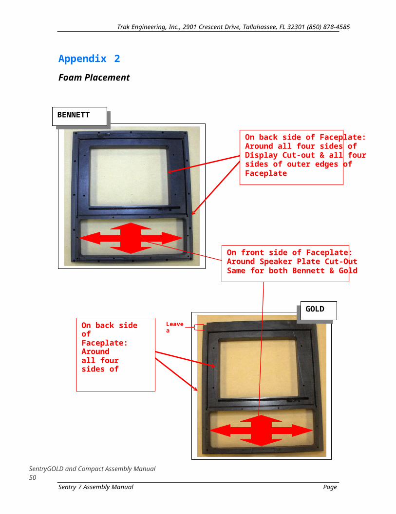
Appendix 2
Foam Placement
BENNETT
On back side of Faceplate:Around all four sides of Display Cut-out & all foursides of outer edges of Faceplate
On front side of Faceplate: Around Speaker Plate Cut-Out Same for both Bennett & Gold
GOLD
SentryGOLD and Compact Assembly Manual 42
Leave a ¼” gap
On back side of Faceplate: Aroundall four sides of Display Cut-out & all Left and Right sides of Faceplate
Sentry 7 Assembly Manual Page 25

Appendix 3
Assembled Display with spacers
SentryGOLD and Compact Assembly Manual 43
Trak Engineering, Inc., 2901 Crescent Drive, Tallahassee, FL 32301 (850) 878-4585

Sentry 7 Assembly Manual
SentryGOLD and Compact Assembly Manual 44
Page 26

Appendix 4
LCD (Carrier) Interface Board
The conLCD Inline up into thethe bac
SentryGOLD and Compact Assembly Manual 45
Page 27
Trak Engineering, Inc., 2901 Crescent Drive, Tallahassee, FL 32301 (850) 878-4585

Sentry 7 Assembly Manual
SentryGOLD and Compact Assembly Manual 46
nector on the terface needs toand be plugged connector on of the Display k

Trak Engineering, Inc., 2901 Crescent Drive, Tallahassee, FL 32301 (850) 878-4585
Appendix 5
MCB Placement
MCB is placed onto these5 screws
MCB Battery
SentryGOLD and Compact Assembly Manual 47

Sentry 7 Assembly Manual Page 28
SentryGOLD and Compact Assembly Manual 48

Appendix 6
SBC Placement
SBC is placed ontothese 4 standoffs.
SentryGOLD and Compact Assembly Manual 49
Sentry 7 Assembly Manual
SentryGOLD and Compact Assembly Manual 50Page 29
Trak Engineering, Inc., 2901 Crescent Drive, Tallahassee, FL 32301 (850) 878-4585

50 PIN CONNECTOR
HEADER 5V
SBC POWER
SentryGOLD and Compact Assembly Manual 51
485 BUS P2 DC J3 POWER
J8 BUSMON
P5
115 VACJ10
J15 / FAN
Trak Engineering, Inc., 2901 Crescent Drive, Tallahassee, FL 32301 (850) 878-4585
Appendix 7
Wiring Diagram
PRINTER
J9
SBC / J2
P2 / P3
SPEAKER J18
J7J17
Sentry 7 Assembly Manual Page 30

Appendix 8
Back Plate Sticker Positioning
SentryGOLD and Compact Assembly Manual 52
Trak Engineering, Inc., 2901 Crescent Drive, Tallahassee, FL 32301 (850) 878-4585
Sentry 7 Assembly Manual
SentryGOLD and Compact Assembly Manual 53
Page 31

Trak Engineering, Inc., 2901 Crescent Drive, Tallahassee, FL 32301 (850) 878-4585
Appendix 9
L’il Bob (Gas Boy Dispenser Circuit Board)
Bus 485 – Power Plug – Pump Handle
Dial, turn counter clockwise
SentryGOLD and Compact Assembly Manual 54

Sentry 7 Assembly Manual Page 32
SentryGOLD and Compact Assembly Manual 55