Embed Size (px)
Citation preview
99mmmm9mmThickness
Pushing a very little loadPushing a very little loadPushing a very little load
Rejection of non-conformingproducts, etc.Rejection of non-conforming products, etc.Rejection of non-conformingproducts, etc.
Parts measurment
(Measured value is displayed)
Maximum pushing forceMaximum pushing forceMaximum pushing force
6 N6 N6 N
Pushing measurementaccuracy
±10 µm±10 µm±10 µm
500 cpm500 cpm500 cpm
Load mass 100 g, Stroke 5 mm
frequencyMaximum operatingfrequency
Positioning a workpiecePositioning a workpiece
Positioning repeatabilityPositioning repeatability
±5 µm±5 µm±5 µmPositioning repeatability
Example) Lens focusingExample) Lens focusing
Example) Pushing a probe pin Example) Pushing a probe pin
Weight
4.6OZ(130 g)
Stroke: 10 mm
The transportation, pushing and length measurement systemshave been miniaturized through the use of a linear motor.The transportation, pushing and length measurement systemshave been miniaturized through the use of a linear motor.
P Easy programming (Takt time entry)
Just input3 parameters: Positioning time, Target position,Load mass.
P Easy programming (Takt time entry)
Just input3 parameters: Positioning time, Target position,Load mass.
Card Motor
Linearmotor
Linearguide
Displacementsensor
3 functions in 1 unit3 functions in 1 unit
CAT.NAS100-96ASeries LAT3
RoHS
NewNew
Model
LAT3m-10LAT3m-20LAT3m-30
W (mm)
50
L (mm)
60
90
120
H (mm)
9
Weight oz (g)
4.6 (130)
6.7 (190)
8.8 (250)
Model StrokeSensor
(Optical linear encoder)
Resolution
Linear motor
Type
Linear guide PushingPositioningrepeatability
Type Instantaneous max. thrust Accuracy
Pushingmeasurement
Maximum load mass Maximumspeed
Accuracy Horizontal
LAT3F
LAT3
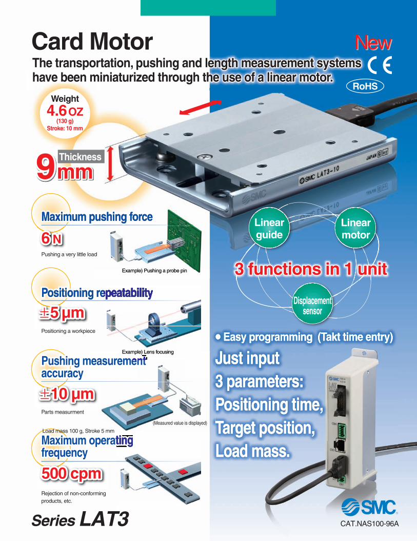
Compact and lightweight
Series Variations
Card Motor
2 body mounting options
Bottom mounting (Body tapped)
Top mounting (Through hole)
Linear guide
Table
The cable connector does not protrude above the actuator.
W
H
L
Linear encoder scale
(Moving side)
Linear encoder sensor head
(Fixed side)
Rail
Permanentmagnet
Coil
The permanent magnet is mounted onthe bottom side of the table, and the coil is mounted on the top surface of the rail. When current is supplied to the coil, a north pole (N) is generated in the middle of the top surface of the coil. This northpole attracts the south pole (S) of the permanent magnet on the left and re-pels the north pole on the right, andthese attracting and repelling forcesgenerate the thrust force. Therefore,thrust force is applied to the table in theright direction, and the table moves tothe right.When current is applied to the coil in the reverse direction, a south pole will be generated in the middle of the top sur-face of the coil. Similarly, a thrust force will be applied to the table in the left di-rection, and the table moves to the left.
Moves in the left direction
NS
S
Force
Moves in theright direction
NS
N
Force
CoilRail
Permanent magnet
Table
102030
1.25 µm Moving magnetictype linear motor
Linear guide withcirculating balls
17.6 oz(500 g)
Vertical
3.5 oz(100 g)
1.8 oz (50 g)400 mm/s
±5 µm
±90 µm
±10 µm
±100 µm30 µm
Positioning dowel pin holes on the workpieceand unit holding parts as standard
Positioning dowelpin holes for theactuator body
Mounting screw holesfor the actuator body(4 locations)
Structure and Working Principle
Cable Mounting
Workpiece Mounting Body Mounting
Workpiece positioning(2 locations)Workpiece mounting
Positioning dowel pin holes for the workpiece
Holding screw holesfor the workpiece(4 locations)
Actuator body positioning(2 locations)
Stopper (to prevent the tablefrom separating from the actuator)
Actuator cable
Card Motor
Table Connector
1.17 lbf (5.2 N)1.35 lbf (6 N)
1.23 lbf (5.5 N)
Features 1
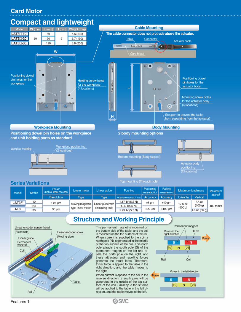
Select the setting for each item described below and register it to the controller by clicking [Setup].
[Card Motor Product Number]: Select the product number of the applicable Card Motor.
[Method to Return to Home Position]: Select home position.
[Card Motor Mounting Orientation]: Select horizontal or vertical.
[Step Data Input Version]: Select takt time entry method.
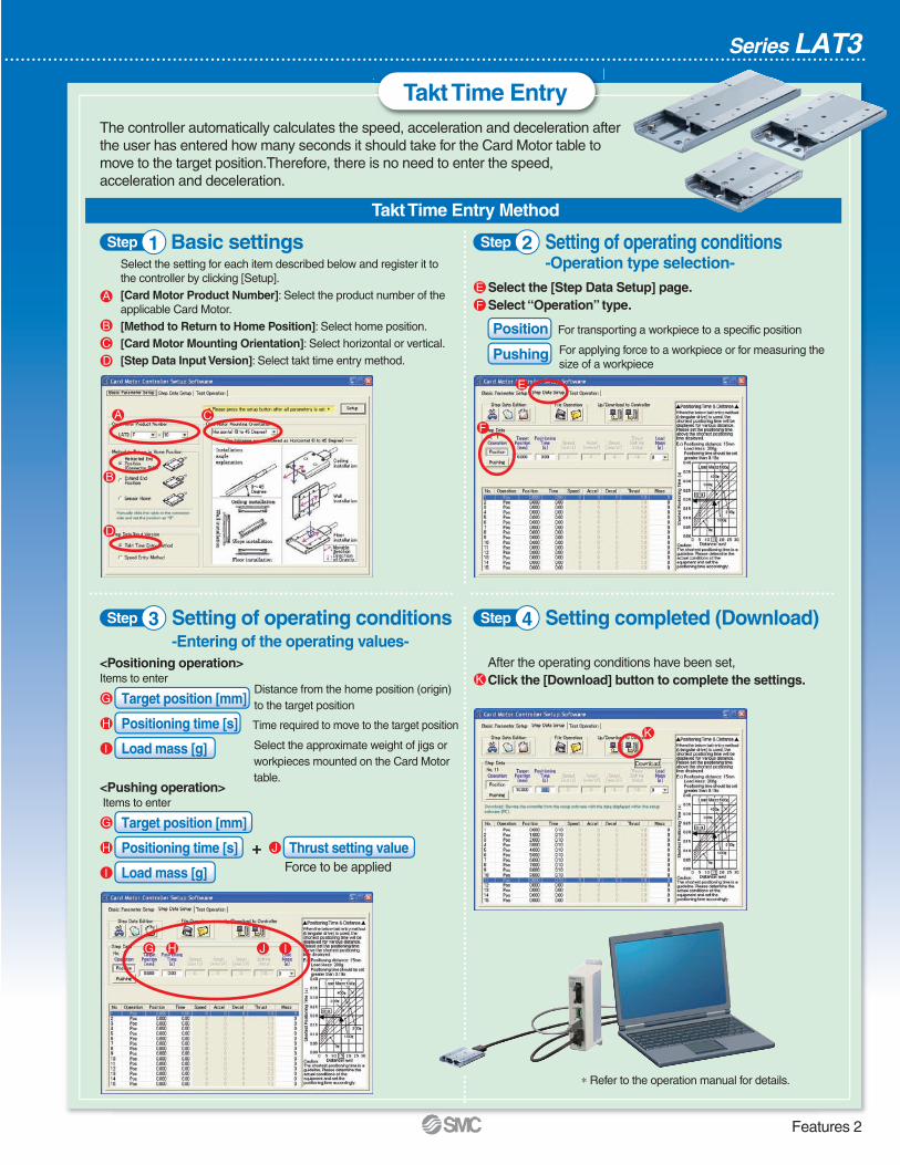
Target position [mm]
Positioning time [s]
Load mass [g]
Takt Time Entry
Basic settings
Series LAT3
A
B
C
D
Takt Time Entry Method
Step 1 Setting of operating conditions-Operation type selection-
Select the [Step Data Setup] page.Select “Operation” type.
Position For transporting a workpiece to a specific position
Pushing For applying force to a workpiece or for measuring thesize of a workpiece
Distance from the home position (origin)to the target position
Time required to move to the target position
Target position [mm]
Positioning time [s] Thrust setting valueForce to be appliedLoad mass [g]
<Pushing operation>Items to enter
<Positioning operation>Items to enter
Step 2
Setting of operating conditions-Entering of the operating values-
Step 3
After the operating conditions have been set, Click the [Download] button to complete the settings.
Setting completed (Download)Step 4
∗ Refer to the operation manual for details.
G
G
H
H
I
I
J
A C
D
G
K
H I
F
E
B
J
E
F
K
+
The controller automatically calculates the speed, acceleration and deceleration afterthe user has entered how many seconds it should take for the Card Motor table tomove to the target position.Therefore, there is no need to enter the speed,acceleration and deceleration.
Select the approximate weight of jigs orworkpieces mounted on the Card Motortable.
Features 2
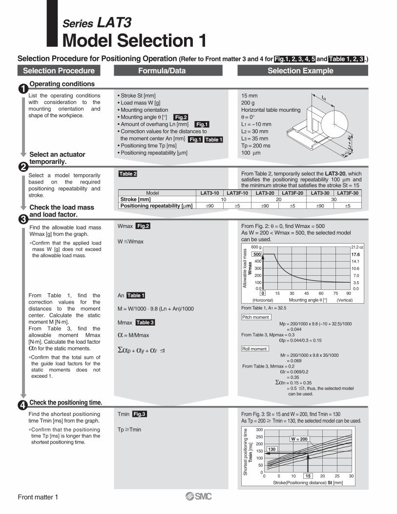
Fig.2
Fig.2
Fig.3
Fig.1
Fig.1 Table 1
Table 1
Table 3
LAT3-10
±90
LAT3F-10
±5
LAT3-20
±90
LAT3F-20
±5
LAT3-30
±90
LAT3F-30
±510 20 30
ModelStroke [mm]Positioning repeatability [µm]
L3
L2+
A2
A1 + L1
0.0100
200
300
400
500
600 g
0
(Horizontal)
15 30 45 60 75 90
(Vertical)Mounting angle θ [°]
Allo
wab
lelo
adm
ass
Wm
ax
0
50
100
150
200
250
300
0 5 10 15 20 25 30
Stroke(Positioning distance) St [mm]
Sho
rtest
posi
tioni
ngtim
eTm
in[m
s]
W = 200
130
Table 2
0.03.5
7.0
10.6
14.1
17.6
21.2 oz
Selection Procedure for Positioning Operation (Refer to Front matter 3 and 4 for Fig.1, 2, 3, 4, 5 and Table 1, 2, 3 .)
Operating conditions1
• Stroke St [mm]• Load mass W [g]• Mounting orientation• Mounting angle θ [°]• Amount of overhang Ln [mm]• Correction values for the distances to the moment center An [mm]• Positioning time Tp [ms]• Positioning repeatability [µm]
15 mm200 gHorizontal table mountingθ = 0°L1 = −10 mmL2 = 30 mmL3 = 35 mmTp = 200 ms100 µm
List the operating conditionswith consideration to themounting orientation andshape of the workpiece.
Select an actuatortemporarily.
2Select a model temporarilybased on the requiredpositioning repeatability andstroke.
From Table 2, temporarily select the LAT3-20, which satisfies the positioning repeatability 100 µm and the minimum stroke that satisfies the stroke St = 15
Check the positioning time.
Tmin
Tp Tmin
An
M = W/1000 · 9.8 (Ln + An)/1000
Mmax
α = M/Mmax
Σαp + αy + αr 1
Mp = 200/1000 x 9.8 (−10 + 32.5)/1000 = 0.044
From Table 3, Mpmax = 0.3αp = 0.044/0.3 = 0.15
From Table 1, A1 = 32.5
Mr = 200/1000 x 9.8 x 35/1000 = 0.069
From Table 3, Mrmax = 0.2αr = 0.069/0.2
= 0.35Σαn = 0.15 + 0.35
= 0.5 1, thus, the selected model can be used.
From Fig. 3: St = 15 and W = 200, find Tmin = 130As Tp = 200 Tmin = 130, the selected model can be used.
Find the shortest positioningtime Tmin [ms] from the graph.
∗Confirm that the positioningtime Tp [ms] is longer than theshortest positioning time.
Check the load massand load factor.3
Wmax
W Wmax
From Fig. 2: θ = 0, find Wmax = 500As W = 200 < Wmax = 500, the selected model can be used.
Find the allowable load mass Wmax [g] from the graph.
∗Confirm that the applied loadmass W [g] does not exceedthe allowable load mass.
From Table 1, find thecorrection values for thedistances to the momentcenter. Calculate the staticmoment M [N·m].From Table 3, find theallowable moment Mmax[N·m]. Calculate the load factorαn for the static moments.
∗Confirm that the total sum ofthe guide load factors for thestatic moments does notexceed 1.
Selection Procedure Formula/Data Selection Example
Pitch moment
Roll moment
4
Front matter 1
Series LAT3Model Selection 1
LAT3-10
30
LAT3F-10
1.25
LAT3-20
30
LAT3F-20
1.25
LAT3-30
30
LAT3F-30
1.2510 20 30
ModelStroke [mm]Measuring accuracy [µm]
L1 + A1
L2+
A2
L3
0123456
0 20 40 60 80 100
Duty ratio [%]
Allo
wab
leth
rust
setti
ngva
lue LAT3m-10
4.2
Ta
Tb
Pos
ition
Time while pushing force is applied
Time
Fig.1
Fig.1 Table 1
Fig.2
Table 1
Table 2
Table 3
Fig.3
Fig.4
Operating conditions1
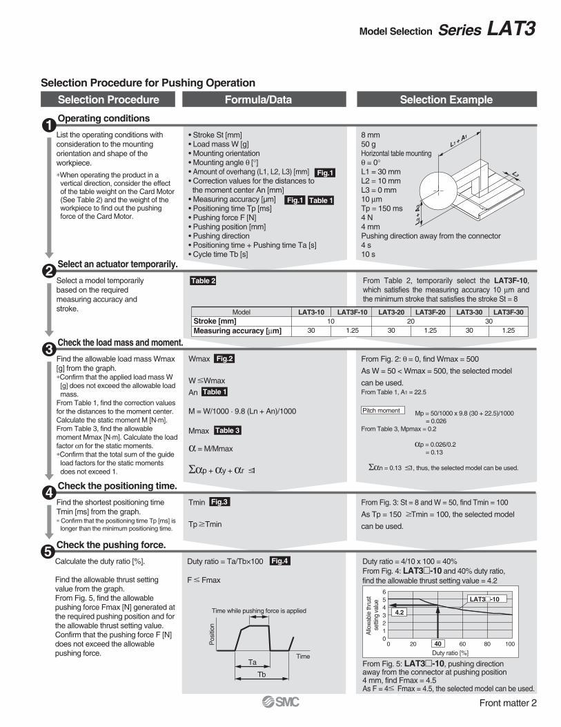
• Stroke St [mm]• Load mass W [g]• Mounting orientation• Mounting angle θ [°]• Amount of overhang (L1, L2, L3) [mm]• Correction values for the distances to the moment center An [mm] • Measuring accuracy [µm]• Positioning time Tp [ms]• Pushing force F [N]• Pushing position [mm]• Pushing direction• Positioning time + Pushing time Ta [s]• Cycle time Tb [s]
8 mm50 gHorizontal table mountingθ = 0°L1 = 30 mmL2 = 10 mmL3 = 0 mm10 µmTp = 150 ms4 N4 mmPushing direction away from the connector4 s10 s
List the operating conditions with consideration to the mounting orientation and shape of the workpiece.
∗When operating the product in avertical direction, consider the effect of the table weight on the Card Motor (See Table 2) and the weight of the workpiece to find out the pushing force of the Card Motor.
Select an actuator temporarily.2
Select a model temporarily based on the required measuring accuracy and stroke.
From Table 2, temporarily select the LAT3F-10,which satisfies the measuring accuracy 10 µm and the minimum stroke that satisfies the stroke St = 8
Check the positioning time.4
Tmin
Tp Tmin
An
M = W/1000 · 9.8 (Ln + An)/1000
Mmax
α = M/Mmax
Σαp + αy + αr 1
Mp = 50/1000 x 9.8 (30 + 22.5)/1000= 0.026
From Table 3, Mpmax = 0.2
αp = 0.026/0.2 = 0.13
Σαn = 0.13 1, thus, the selected model can be used.
From Table 1, A1 = 22.5
From Fig. 3: St = 8 and W = 50, find Tmin = 100
As Tp = 150 Tmin = 100, the selected model
can be used.
Find the shortest positioning timeTmin [ms] from the graph.∗ Confirm that the positioning time Tp [ms] is
longer than the minimum positioning time.
Check the load mass and moment.3
From Fig. 2: θ = 0, find Wmax = 500
As W = 50 < Wmax = 500, the selected model
can be used.
Find the allowable load mass Wmax [g] from the graph.∗Confirm that the applied load mass W [g] does not exceed the allowable load mass.
From Table 1, find the correction values for the distances to the moment center. Calculate the static moment M [N·m].From Table 3, find the allowable moment Mmax [N·m]. Calculate the load factor αn for the static moments.∗Confirm that the total sum of the guide load factors for the static moments does not exceed 1.
Selection Procedure Formula/Data Selection Example
Selection Procedure for Pushing Operation
Check the pushing force.5
Duty ratio = Ta/Tb×100
F Fmax
Duty ratio = 4/10 x 100 = 40%From Fig. 4: LAT3m-10 and 40% duty ratio, find the allowable thrust setting value = 4.2
From Fig. 5: LAT3m-10, pushing direction away from the connector at pushing position 4 mm, find Fmax = 4.5As F = 4 Fmax = 4.5, the selected model can be used.
Calculate the duty ratio [%].
Find the allowable thrust settingvalue from the graph.From Fig. 5, find the allowablepushing force Fmax [N] generated atthe required pushing position and forthe allowable thrust setting value.Confirm that the pushing force F [N]does not exceed the allowablepushing force.
Pitch moment
Wmax
W Wmax
Front matter 2
Model Selection Series LAT3
0.0
100
200
300
400
500
600 g
0(Horizontal)
15 30 45 60 75 90 (Vertical)Mounting angle θ [°]
Allo
wab
lelo
adm
ass
Wm
ax
LAT3m-10, -20
LAT3m-30
600
150
200
300
120
100
86
75
Fre
quen
cy[c
pm]
0
50
100
150
200
250
300
600
300
200
150
120
100
0 5 10 15 20 25 30Stroke(Positioning distance) St [mm]
Sho
rtes
tpos
ition
ing
time
Tm
in[m
s]
Fre
quen
cy[c
pm]
W = 0W = 100
W = 200
W = 300
W = 400W = 500
0
50
100
150
200
250
300
350
400
0 5 10 15 20 25 30Stroke(Positioning distance) St [mm]
Sho
rtes
tpos
ition
ing
time
Tm
in[m
s]
W = 0W = 100
W = 200
W = 300W = 400
W = 500
0.0
3.5
7.0
10.6
14.1
17.6
21.2 oz
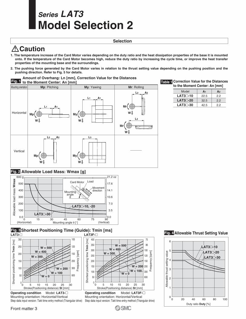
Fig. 1
Fig. 2
Fig. 3
Mp: PitchingMounting orientation
Horizontal
Vertical
My: Yawing Mr: Rolling
Amount of Overhang: Ln [mm], Correction Value for the Distances to the Moment Center: An [mm] Correction Value for the Distances
to the Moment Center: An [mm]Table 1
A1 A2
22.5
32.5
42.5
2.2
2.2
2.2
Model
LAT3m-10LAT3m-20LAT3m-30
Allowable Load Mass: Wmax [g]
LAT3-m LAT3F-m
Operating condition Model: LAT3F-mMounting orientation: Horizontal/VerticalStep data input version: Takt time entry method (Triangular drive)
Shortest Positioning Time (Guide): Tmin [ms]
Operating condition Model: LAT3-mMounting orientation: Horizontal/VerticalStep data input version: Takt time entry method (Triangular drive)
Mountingangle
θ
LoadCard Motor
Movementdirection
Selection
Caution1. The temperature increase of the Card Motor varies depending on the duty ratio and the heat dissipation properties of the base it is mounted
onto. If the temperature of the Card Motor becomes high, reduce the duty ratio by increasing the cycle time, or improve the heat transferproperties of the mounting base and the surroundings.
2. The pushing force generated by the Card Motor varies in relation to the thrust setting value depending on the pushing position and the pushing direction. Refer to Fig. 5 for details.
Mp My
W W
Mp
W
Mr
W
Mr
W
My
W
L1 A1
L1 A1
L2 A2
L3
L2 A2 L3
Fig. 4 Allowable Thrust Setting Value
0
1
2
3
4
5
6
0 20 40 60 80 100
Duty ratio Duty [%]
Allo
wab
leth
rust
setti
ngva
lue
LAT3m-10
LAT3m-20
LAT3m-30
Front matter 3
Series LAT3Model Selection 2
40A1
40A1
40
0
1
2
3
4
5
6 N
0 2 4 6 8 10
Pushing position [mm]
Pus
hing
forc
e
0
1
2
3
4
5
6 N
0 2 4 6 8 10Pushing position [mm]
Pus
hing
forc
e
0
1
2
3
4
5
6 N
0 5 10 15 20Pushing position [mm]
Pus
hing
forc
e
0
1
2
3
4
5
6 N
0 5 10 15 20Pushing position [mm]
Pus
hing
forc
e
0
1
2
3
4
5
6 N
0 5 10 15 20 25 30Pushing position [mm]
Pus
hing
forc
e
0
1
2
3
4
5
6 N
0 5 10 15 20 25 30Pushing position [mm]
Pus
hing
forc
e
Thrust setting value: 4.8Thrust setting value: 5
Thrust setting value: 3
Thrust setting value: 1
Thrust setting value: 5
Thrust setting value: 3
Thrust setting value: 1
Thrust setting value: 3.9
Thrust setting value: 2.6
Thrust setting value: 1
Thrust setting value: 2.8
Thrust setting value: 1
Thrust setting value: 4.8Thrust setting value: 3.9
Thrust setting value: 2.6
Thrust setting value: 1Thrust setting value: 2.8
Thrust setting value: 1
0.00
0.01
0.02
0.03
0.04
0.05
0 2 4 6 NLoad
Tab
ledi
spla
cem
ent[
mm
]
0.00
0.01
0.02
0.03
0.04
0.05
0 2 4 6 NLoad
Tab
ledi
spla
cem
ent[
mm
]
0.00
0.02
0.04
0.06
0.08
0 2 4 6 NLoad
Tab
ledi
spla
cem
ent[
mm
]0 0.4 0.9 1.3 lbf 0 0.4 0.9 1.3 lbf 0 0.4 0.9 1.3 lbf
1.3 lbf
1.1
0.9
0.7
0.4
0.2
0
1.3 lbf
1.1
0.9
0.7
0.4
0.2
0
1.3 lbf
1.1
0.9
0.7
0.4
0.2
0
1.3 lbf
1.1
0.9
0.7
0.4
0.2
0
1.3 lbf
1.1
0.9
0.7
0.4
0.2
0
1.3 lbf
1.1
0.9
0.7
0.4
0.2
0
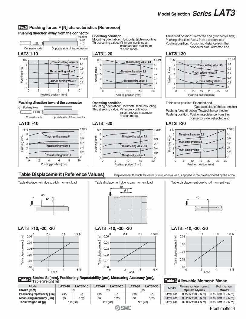
Fig.5 Pushing force: F [N] characteristics (Reference)
LAT3m-10 LAT3m-20 LAT3m-30
LAT3m-10, -20, -30 LAT3m-10, -20, -30 LAT3m-10, -20, -30
LAT3-10
±9030
LAT3F-10
±51.25
LAT3-20
±9030
LAT3F-20
±51.25
LAT3-30
±9030
LAT3F-30
±51.25
10
1.8 (50)
20
2.5 (70)
30
3.2 (90)
ModelStroke [mm]Positioning repeatability [µm]Measuring accuracy [µm]Table weight oz [g]
Table 2 Table 3Stroke: St [mm], Positioning Repeatability [µm], Measuring Accuracy [µm],Table Weight [g]
Pitch moment/Yaw moment Mpmax, Mymax
Roll momentMrmax
0.15 lbf•ft (0.2 N•m)0.22 lbf•ft (0.3 N•m)0.30 lbf•ft (0.4 N•m)
0.15 lbf•ft (0.2 N•m)0.15 lbf•ft (0.2 N•m)0.15 lbf•ft (0.2 N•m)
Model
LAT3m-10LAT3m-20LAT3m-30
Allowable Moment: Mmax
Table Displacement (Reference Values)
Table displacement due to pitch moment load
Pushingforce
Pushing force
Pushing direction away from the connector
Pushing direction toward the connector
Opposite side of the connectorConnector side
Opposite side of the connectorConnector side
Table displacement due to yaw moment load Table displacement due to roll moment load
Displacement through the entire stroke when a load is applied to the point indicated by the arrow
LAT3m-10 LAT3m-20 LAT3m-30
Operating conditionMounting orientation: Horizontal table mountingThrust setting value: Minimum, continuous,
instantaneous maximumof each model.
Table start position: Retracted end (Connector side)Pushing direction: Away from the connectorPushing position: Positioning distance from the
connector side, retracted end
Operating conditionMounting orientation: Horizontal table mountingThrust setting value: Minimum, continuous,
instantaneous maximumof each model.
Table start position: Extended end(Opposite side of the connector)
Pushing force direction: Toward the connectorPushing position: Positioning distance from the
connector side, retrected end
Front matter 4
Model Selection Series LAT3
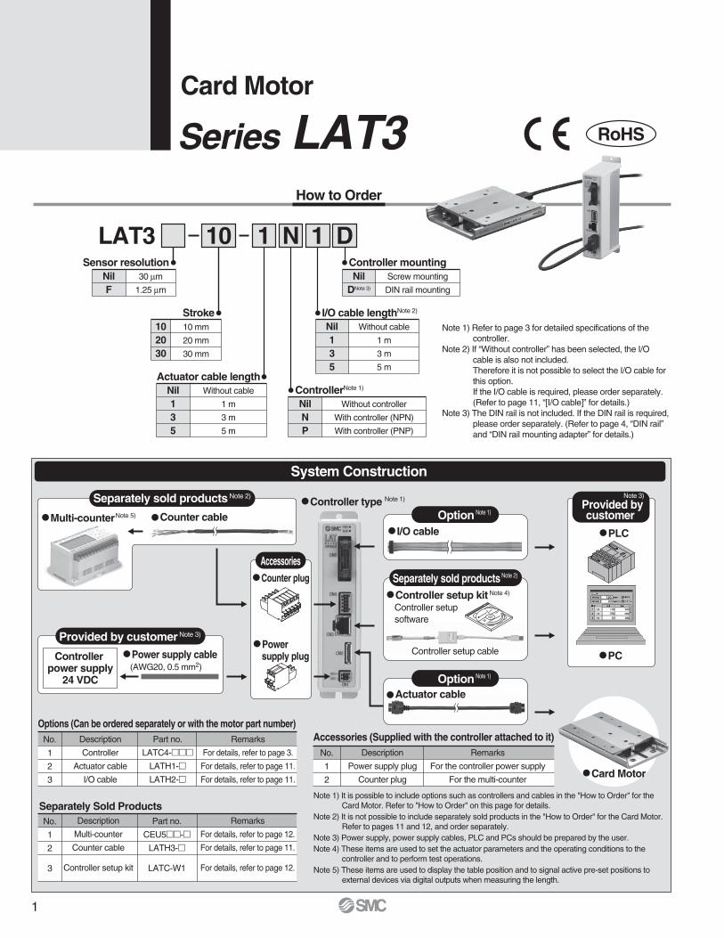
How to Order
1 N 1 DLAT3 10Sensor resolution
NilF
30 µm
1.25 µm
Stroke102030
10 mm
20 mm
30 mm
Actuator cable lengthNil135
Without cable
1 m
3 m
5 m
ControllerNote 1)
NilNP
Without controller
With controller (NPN)
With controller (PNP)
I/O cable lengthNote 2)
Nil135
Without cable
1 m
3 m
5 m
Controller mountingNil
DNote 3)
Screw mounting
DIN rail mounting
System Construction
Q Multi-counterNote 5)
Q Controller setup kit Note 4)
Controller setupsoftware
Q Counter plug
Q Power supply cable (AWG20, 0.5 mm2)
Q I/O cable
Q Actuator cable
Q PLC
Q PCQ Power
supply plugControllerpower supply
24 VDC
Provided bycustomer
Provided by customer Note 3)
Separately sold products Note 2)
Accessories
Option Note 1)
Separately sold products Note 2)
Option Note 1)
Q Card Motor
Controller setup cable
Options (Can be ordered separately or with the motor part number)No.
1
2
3
Description
Controller
Actuator cable
I/O cable
Part no.
LATC4-mmmLATH1-mLATH2-m
Remarks
For details, refer to page 3.
For details, refer to page 11.
For details, refer to page 11.
Accessories (Supplied with the controller attached to it)No.
1
2
Description
Power supply plug
Counter plug
Remarks
For the controller power supply
For the multi-counter
Separately Sold ProductsNo.
1
2
3
Description
Multi-counter
Counter cable
Controller setup kit
Part no.
CEU5mm-mLATH3-m
LATC-W1
Remarks
For details, refer to page 12.
For details, refer to page 11.
For details, refer to page 12.
Note 1) It is possible to include options such as controllers and cables in the "How to Order" for the Card Motor. Refer to "How to Order" on this page for details.
Note 2) It is not possible to include separately sold products in the "How to Order" for the Card Motor. Refer to pages 11 and 12, and order separately.
Note 3) Power supply, power supply cables, PLC and PCs should be prepared by the user.Note 4) These items are used to set the actuator parameters and the operating conditions to the
controller and to perform test operations.Note 5) These items are used to display the table position and to signal active pre-set positions to
external devices via digital outputs when measuring the length.
Q Controller type Note 1)
Q Counter cable
Card Motor
Series LAT3 RoHS
Note 1) Refer to page 3 for detailed specifications of the controller.
Note 2) If “Without controller” has been selected, the I/O cable is also not included.Therefore it is not possible to select the I/O cable forthis option.If the I/O cable is required, please order separately. (Refer to page 11, “[I/O cable]” for details.)
Note 3) The DIN rail is not included. If the DIN rail is required, please order separately. (Refer to page 4, “DIN rail” and “DIN rail mounting adapter” for details.)
Note 3)
1
depth 2+0.03
0ø3
7.5
dept
h2
+0.0
50
3
3.5
6.5
Not
e2)
Note 2)
Rail dowel pin hole
7
4.7
ø5.
2
depth 1.5+0.030ø3
depth 1.5+0.05 03
3.5(R43)
Min. cable bending radius
Note 2)
Note 1)
Note 2)
Table positioning hole
(Rail dowel pin hole)
E
Stroke: A
G 20±0.1
23 68
20 (Fixed part of the cable)
20
Actuator cable
C x M3 x 0.5 depth 2.5Table mounting screw
DB
259.5
HTable
Rail
32
49(T
able
wid
th)
50
9
F
24
Note 1)4 × M3 × 0.5 depth 2Rail mounting screw
32±0.116
20Moving magnetic type linear motor
1.35 lbf (6 N)0.63 lbf (2.8 N)
Linear guide with circulating balls
Optical linear encoder (incremental)
61 to 4.8
40041 to 104°F (5 to 40°C) (No condensation)
35 to 85 (No condensation)6.7 (190)2.5 (70)
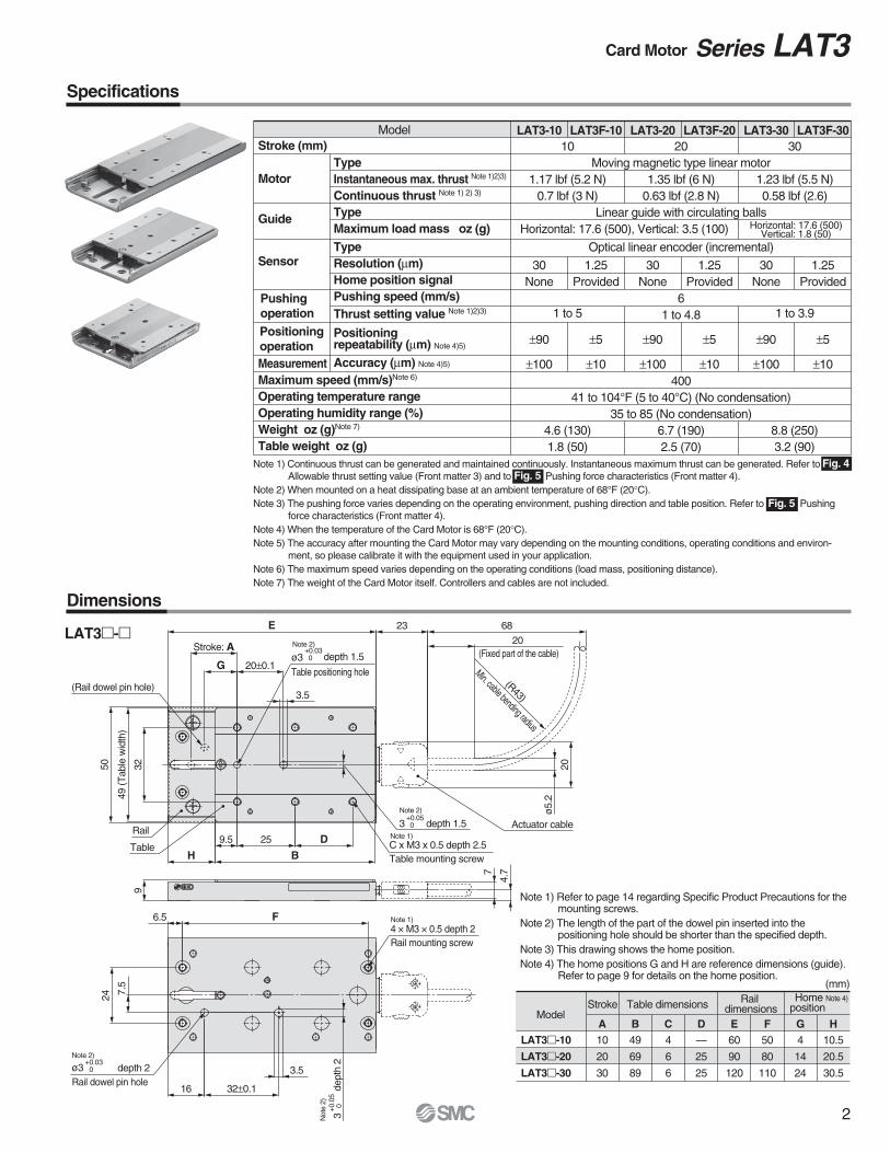
Specifications
Dimensions
LAT3m-m
Stroke Table dimensions Rail dimensions
Homeposition
ModelA B C D10
20
30
49
69
89
4
6
6
—
25
25
E60
90
120
F50
80
110
G4
14
24
H10.5
20.5
30.5
(mm)
LAT3m-10
LAT3m-20
LAT3m-30
LAT3-10
30None
±90
±100
LAT3F-10
1.25Provided
±5
±10
LAT3-20
30None
±90
±100
LAT3F-20
1.25Provided
±5
±10
LAT3-30
30None
±90
±100
LAT3F-30
1.25Provided
±5
±10
10
1.17 lbf (5.2 N)0.7 lbf (3 N)
1 to 5
4.6 (130)1.8 (50)
30
1.23 lbf (5.5 N)0.58 lbf (2.6)
1 to 3.9
8.8 (250)3.2 (90)
ModelStroke (mm)
Motor
Guide
Sensor
MeasurementMaximum speed (mm/s)Note 6)
Operating temperature rangeOperating humidity range (%)Weight oz (g)Note 7)
Table weight oz (g)
TypeInstantaneous max. thrust Note 1)2)3)
Continuous thrust Note 1) 2) 3)
TypeMaximum load mass oz (g)TypeResolution (µm)Home position signalPushing speed (mm/s)Thrust setting value Note 1)2)3)
Positioningrepeatability (µm) Note 4)5)
Accuracy (µm) Note 4)5)
Note 1) Refer to page 14 regarding Specific Product Precautions for the mounting screws.
Note 2) The length of the part of the dowel pin inserted into the positioning hole should be shorter than the specified depth.
Note 3) This drawing shows the home position.Note 4) The home positions G and H are reference dimensions (guide).
Refer to page 9 for details on the home position.
Horizontal: 17.6 (500), Vertical: 3.5 (100)
Positioning operation
Pushing operation
Note 1) Continuous thrust can be generated and maintained continuously. Instantaneous maximum thrust can be generated. Refer to Allowable thrust setting value (Front matter 3) and to Pushing force characteristics (Front matter 4).
Note 2) When mounted on a heat dissipating base at an ambient temperature of 68°F (20°C).Note 3) The pushing force varies depending on the operating environment, pushing direction and table position. Refer to Pushing
force characteristics (Front matter 4).Note 4) When the temperature of the Card Motor is 68°F (20°C).Note 5) The accuracy after mounting the Card Motor may vary depending on the mounting conditions, operating conditions and environ-
ment, so please calibrate it with the equipment used in your application.Note 6) The maximum speed varies depending on the operating conditions (load mass, positioning distance).Note 7) The weight of the Card Motor itself. Controllers and cables are not included.
Fig. 5
Fig. 5
Fig. 4
Horizontal: 17.6 (500)Vertical: 1.8 (50)
Note 4)
2
Card Motor Series LAT3
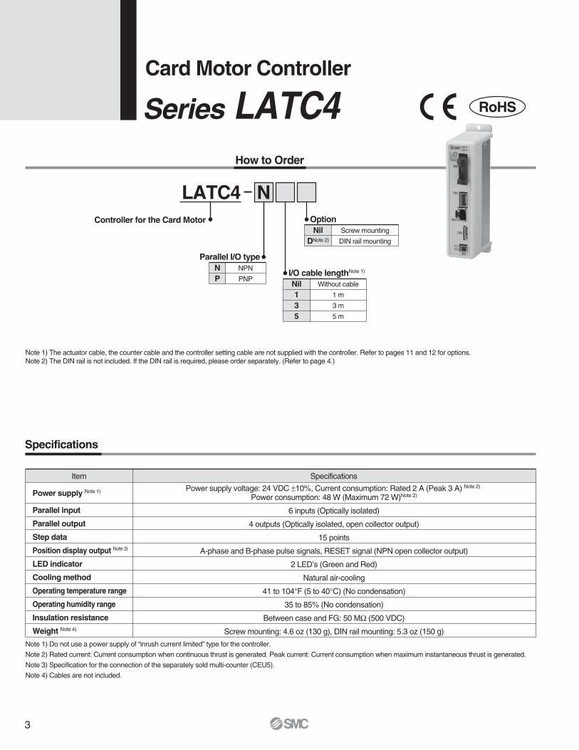
How to Order
Note 1) Do not use a power supply of “inrush current limited” type for the controller.
Note 2) Rated current: Current consumption when continuous thrust is generated. Peak current: Current consumption when maximum instantaneous thrust is generated.
Note 3) Specification for the connection of the separately sold multi-counter (CEU5).
Note 4) Cables are not included.
Note 1) The actuator cable, the counter cable and the controller setting cable are not supplied with the controller. Refer to pages 11 and 12 for options.Note 2) The DIN rail is not included. If the DIN rail is required, please order separately. (Refer to page 4.)
LATC4 NOptionNil
DNote 2)
Screw mounting
DIN rail mounting
I/O cable lengthNote 1)
Nil135
Without cable
1 m
3 m
5 m
Parallel I/O typeNP
NPN
PNP
Controller for the Card Motor
Item Specifications
Power supply voltage: 24 VDC ±10%, Current consumption: Rated 2 A (Peak 3 A) Note 2) Power consumption: 48 W (Maximum 72 W)Note 2)
6 inputs (Optically isolated)
4 outputs (Optically isolated, open collector output)
15 points
A-phase and B-phase pulse signals, RESET signal (NPN open collector output)
2 LED’s (Green and Red)
Natural air-cooling
41 to 104°F (5 to 40°C) (No condensation)
35 to 85% (No condensation)
Between case and FG: 50 MΩ (500 VDC)
Screw mounting: 4.6 oz (130 g), DIN rail mounting: 5.3 oz (150 g)
Power supply Note 1)
Parallel input
Parallel output
Step data
Position display output Note 3)
LED indicator
Cooling method
Operating temperature range
Operating humidity range
Insulation resistance
Weight Note 4)
Specifications
Card Motor Controller
Series LATC4 RoHS
3
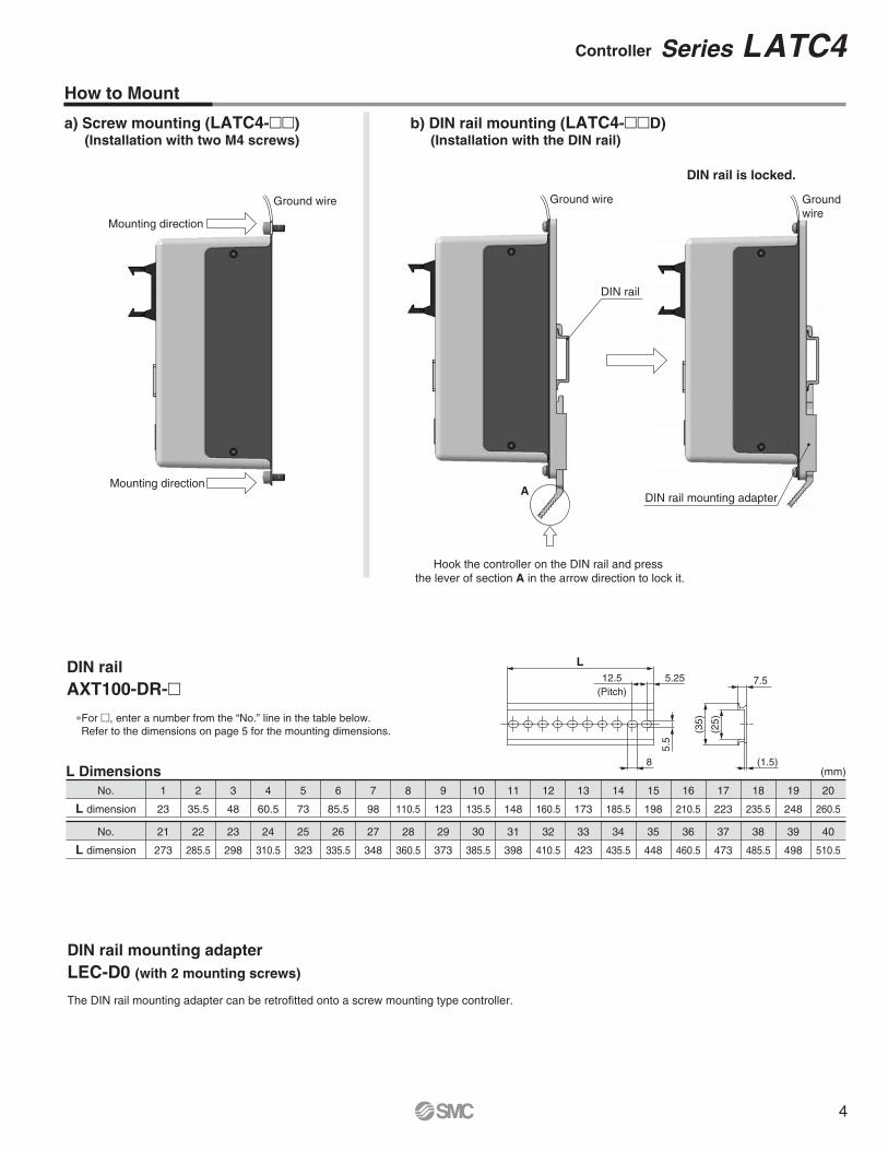
a) Screw mounting (LATC4-mm)(Installation with two M4 screws)
b) DIN rail mounting (LATC4-mmD)(Installation with the DIN rail)
Ground wire
DIN rail
DIN rail is locked.
Mounting direction
Mounting direction
Ground wire Groundwire
Hook the controller on the DIN rail and pressthe lever of section A in the arrow direction to lock it.
DIN railAXT100-DR-m
∗For m, enter a number from the “No.” line in the table below. Refer to the dimensions on page 5 for the mounting dimensions.
40
510.5
39
498
38
485.5
37
473
36
460.5
35
448
34
435.5
33
423
32
410.5
31
398
30
385.5
29
373
28
360.5
27
348
26
335.5
25
323
24
310.5
23
298
22
285.5
21
273
No.
L dimension
20
260.5
19
248
18
235.5
17
223
16
210.5
15
198
14
185.5
13
173
12
160.5
11
148
10
135.5
9
123
8
110.5
7
98
6
85.5
5
73
4
60.5
3
48
2
35.5
1
23
No.
L dimension
L Dimensions
L
7.5
(25)
(35)
ADIN rail mounting adapter
DIN rail mounting adapterLEC-D0 (with 2 mounting screws)
The DIN rail mounting adapter can be retrofitted onto a screw mounting type controller.
5.5
5.2512.5(Pitch)
8 (1.5)(mm)
4
How to Mount
Controller Series LATC4
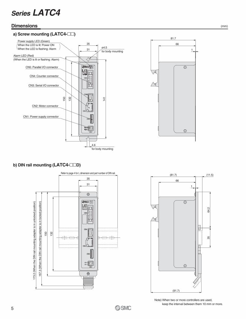
35
31
141
132
150
4.6for body mounting
Alarm LED (Red)(When the LED is lit or flashing: Alarm)
CN5: Parallel I/O connector
CN4: Counter connector
CN3: Serial I/O connector
CN2: Motor connector
CN1: Power supply connector
66
81.7
1
31
35
132
150
167.
3(W
hen
the
DIN
rail
mou
ntin
gad
apte
ris
inlo
cked
posi
tion)
173.
2(W
hen
the
DIN
rail
mou
ntin
gad
apte
ris
inun
lock
edpo
sitio
n)
66
(81.7)
64.2
35
(91.7)
1
(11.5)
Power supply LED (Green)When the LED is lit: Power ONWhen the LED is flashing: Alarm
Refer to page 4 for L dimension and part number of DIN rail.
ø4.5for body mounting
a) Screw mounting (LATC4-mm)
b) DIN rail mounting (LATC4-mmD)
Note) When two or more controllers are used,keep the interval between them 10 mm or more.
Dimensions
5
Series LATC4(mm)
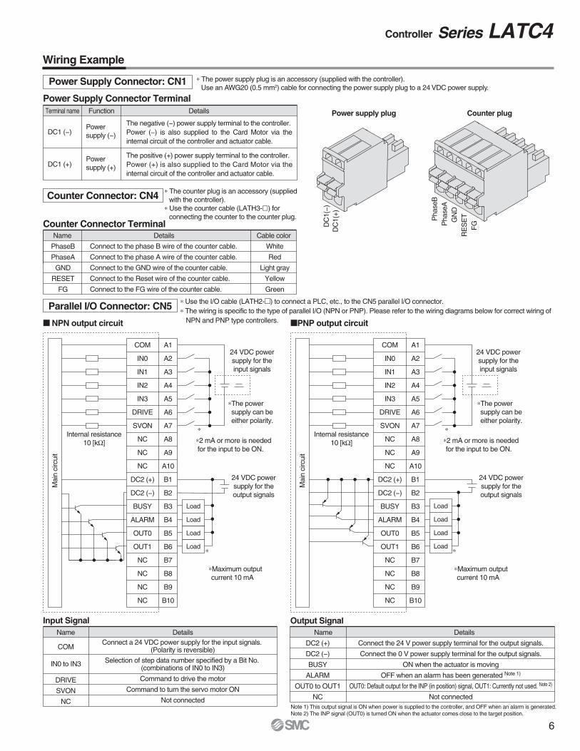
Power Supply Connector: CN1
Terminal name Details
DC1 (−)
DC1 (+)
Function
Powersupply (−)
Power Supply Connector Terminal
Counter Connector: CN4
Name Details Cable color
Connect to the phase B wire of the counter cable.
Connect to the phase A wire of the counter cable.
Connect to the GND wire of the counter cable.
Connect to the Reset wire of the counter cable.
Connect to the FG wire of the counter cable.
White
Red
Light gray
Yellow
Green
PhaseB
PhaseA
GND
RESET
FG
Counter Connector Terminal
Name DetailsConnect a 24 VDC power supply for the input signals.
(Polarity is reversible)
Selection of step data number specified by a Bit No.(combinations of IN0 to IN3)
Command to drive the motor
Command to turn the servo motor ON
Not connected
COM
IN0 to IN3
DRIVE
SVON
NC
Input SignalName Details
Connect the 24 V power supply terminal for the output signals.
Connect the 0 V power supply terminal for the output signals.
ON when the actuator is moving
OFF when an alarm has been generated Note 1)
OUT0: Default output for the INP (in position) signal, OUT1: Currently not used. Note 2)
Not connected
DC2 (+)
DC2 (−)
BUSY
ALARM
OUT0 to OUT1
NC
Output Signal
∗ The counter plug is an accessory (suppliedwith the controller).
∗ Use the counter cable (LATH3-l) forconnecting the counter to the counter plug.
Parallel I/O Connector: CN5
Power supply plug Counter plug
DC
1(−)
DC
1(+)
24 VDC powersupply for theinput signals
Mai
nci
rcui
t
24 VDC powersupply for theoutput signals
Load
Load
Load
Load
Internal resistance10 [kΩ]
∗The powersupply can beeither polarity.
∗The power supply can be either polarity.
24 VDC powersupply for theinput signals
24 VDC powersupply for theoutput signals
Load
Load
Load
Internal resistance10 [kΩ]
Load
Pha
seB
Pha
seA
GN
DR
ES
ET
FG
M NPN output circuit MPNP output circuit
∗ Use the I/O cable (LATH2-m) to connect a PLC, etc., to the CN5 parallel I/O connector.∗ The wiring is specific to the type of parallel I/O (NPN or PNP). Please refer to the wiring diagrams below for correct wiring of
NPN and PNP type controllers.
∗ The power supply plug is an accessory (supplied with the controller).Use an AWG20 (0.5 mm2) cable for connecting the power supply plug to a 24 VDC power supply.
Note 1) This output signal is ON when power is supplied to the controller, and OFF when an alarm is generated.Note 2) The INP signal (OUT0) is turned ON when the actuator comes close to the target position.
∗ ∗
∗
∗Maximum outputcurrent 10 mA
∗2 mA or more is needed for the input to be ON.
∗∗2 mA or more is neededfor the input to be ON.
∗Maximum output current 10 mA
The negative (−) power supply terminal to the controller.Power (−) is also supplied to the Card Motor via the internal circuit of the controller and actuator cable.
The positive (+) power supply terminal to the controller.Power (+) is also supplied to the Card Motor via the internal circuit of the controller and actuator cable.
COM
IN0
IN1
IN2
IN3
DRIVE
SVON
NC
NC
NC
DC2 (+)
DC2 (−)
BUSY
ALARM
OUT0
OUT1
NC
NC
NC
NC
A1
A2
A3
A4
A5
A6
A7
A8
A9
A10
B1
B2
B3
B4
B5
B6
B7
B8
B9
B10
Mai
nci
rcui
t
COM
IN0
IN1
IN2
IN3
DRIVE
SVON
NC
NC
NC
DC2 (+)
DC2 (−)
BUSY
ALARM
OUT0
OUT1
NC
NC
NC
NC
A1
A2
A3
A4
A5
A6
A7
A8
A9
A10
B1
B2
B3
B4
B5
B6
B7
B8
B9
B10
Powersupply (+)
6
Wiring Example
Controller Series LATC4
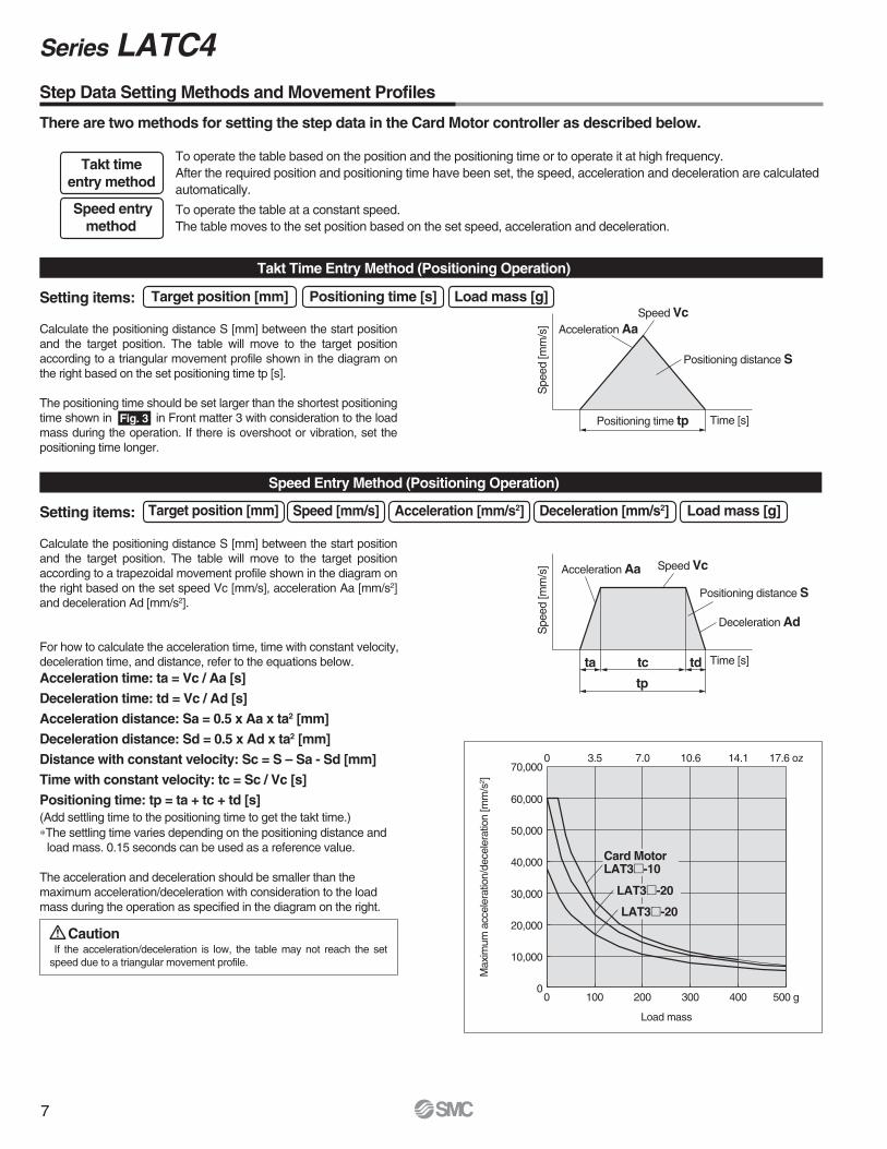
Takt timeentry method
Speed entrymethod
There are two methods for setting the step data in the Card Motor controller as described below.
Setting items:
To operate the table based on the position and the positioning time or to operate it at high frequency.After the required position and positioning time have been set, the speed, acceleration and deceleration are calculatedautomatically.
To operate the table at a constant speed.The table moves to the set position based on the set speed, acceleration and deceleration.
Calculate the positioning distance S [mm] between the start position and the target position. The table will move to the target positionaccording to a triangular movement profile shown in the diagram onthe right based on the set positioning time tp [s].
The positioning time should be set larger than the shortest positioningtime shown in in Front matter 3 with consideration to the load mass during the operation. If there is overshoot or vibration, set thepositioning time longer.
Takt Time Entry Method (Positioning Operation)
Target position [mm]
Target position [mm]
Positioning time [s] Load mass [g]
Setting items:
Calculate the positioning distance S [mm] between the start position and the target position. The table will move to the target positionaccording to a trapezoidal movement profile shown in the diagram on the right based on the set speed Vc [mm/s], acceleration Aa [mm/s2]and deceleration Ad [mm/s2].
The acceleration and deceleration should be smaller than the maximum acceleration/deceleration with consideration to the loadmass during the operation as specified in the diagram on the right.
If the acceleration/deceleration is low, the table may not reach the set speed due to a triangular movement profile.
For how to calculate the acceleration time, time with constant velocity,deceleration time, and distance, refer to the equations below.
(Add settling time to the positioning time to get the takt time.)∗The settling time varies depending on the positioning distance and
load mass. 0.15 seconds can be used as a reference value.
Speed Entry Method (Positioning Operation)
Speed [mm/s] Acceleration [mm/s2] Deceleration [mm/s2] Load mass [g]
Acceleration time: ta = Vc / Aa [s]Deceleration time: td = Vc / Ad [s]Acceleration distance: Sa = 0.5 x Aa x ta2 [mm]Deceleration distance: Sd = 0.5 x Ad x ta2 [mm]Distance with constant velocity: Sc = S – Sa - Sd [mm]Time with constant velocity: tc = Sc / Vc [s]Positioning time: tp = ta + tc + td [s]
Caution
Speed Vc
Positioning time tp
Acceleration Aa
Positioning distance S
Time [s]
Spe
ed[m
m/s
]
Speed Vc
tp
ta tdtc
Acceleration Aa
Positioning distance S
Time [s]
Spe
ed[m
m/s
]
Deceleration Ad
0
10,000
20,000
30,000
40,000
50,000
60,000
70,000
0 100 200 300 400 500 g
Load mass
Max
imum
acce
lera
tion/
dece
lera
tion
[mm
/s2 ]
Card MotorLAT3m-10
LAT3m-20
LAT3m-20
Fig. 3
0 3.5 7.0 10.6 14.1 17.6 oz
Step Data Setting Methods and Movement Profiles
7
Series LATC4
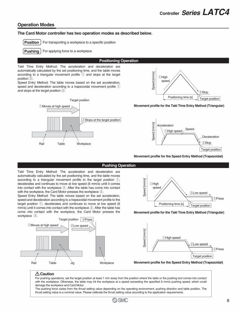
Position
Pushing
The Card Motor controller has two operation modes as described below.
For transporting a workpiece to a specific position
For applying force to a workpiece
Takt Time Entry Method: The acceleration and deceleration are automatically calculated by the set positioning time, and the table movesaccording to a triangular movement profile q and stops at the target position w.Speed Entry Method: The table moves based on the set acceleration, speed and deceleration according to a trapezoidal movement profile qand stops at the target position w.
Positioning Operation
Takt Time Entry Method: The acceleration and deceleration areautomatically calculated by the set positioning time, and the table movesaccording to a triangular movement profile to the target position q,decelerates and continues to move at low speed (6 mm/s) until it comesinto contact with the workpiece w. After the table has come into contact with the workpiece, the Card Motor presses the workpiece e.Speed Entry Method: The table moves based on the set acceleration, speed and deceleration according to a trapezoidal movement profile to thetarget position q, decelerates and continues to move at low speed (6 mm/s) until it comes into contact with the workpiece w. After the table hascome into contact with the workpiece, the Card Motor presses theworkpiece e.
For pushing operations, set the target position at least 1 mm away from the position where the table or the pushing tool comes into contact with the workpiece. Otherwise, the table may hit the workpiece at a speed exceeding the specified 6 mm/s pushing speed, which could damage the workpiece and Card Motor.The pushing force varies from the thrust setting value depending on the operating environment, pushing direction and table position. The thrust setting value is a nominal value. Please calibrate the thrust setting value according to the application requirements.
Pushing Operation
Caution
Positioning time [s]
Movement profile for the Takt Time Entry Method (Triangular)
Movement profile for the Speed Entry Method (Trapezoidal)
qHighspeed
wStop
wStop
Spe
ed[m
m/s
]
SpeedqHigh speed
Acceleration
qMoves at high speed
wStops at the target position
Target position
Workpiece
Spe
ed[m
m/s
]
Deceleration
Target position
Target position
Target position
Target position
Positioning time [s]
Movement profile for the Takt Time Entry Method (Triangular)
Movement profile for the Speed Entry Method (Trapezoidal)
qHighspeed
wLow speed
ePress
ePress
Spe
ed[m
m/s
]
qHigh speed
wLow speed
Spe
ed[m
m/s
]
ePress
qMoves at high speed
Target position
Jig
wLow speed
Rail Table
Rail Table
Workpiece
8
Controller Series LATC4Operation Modes
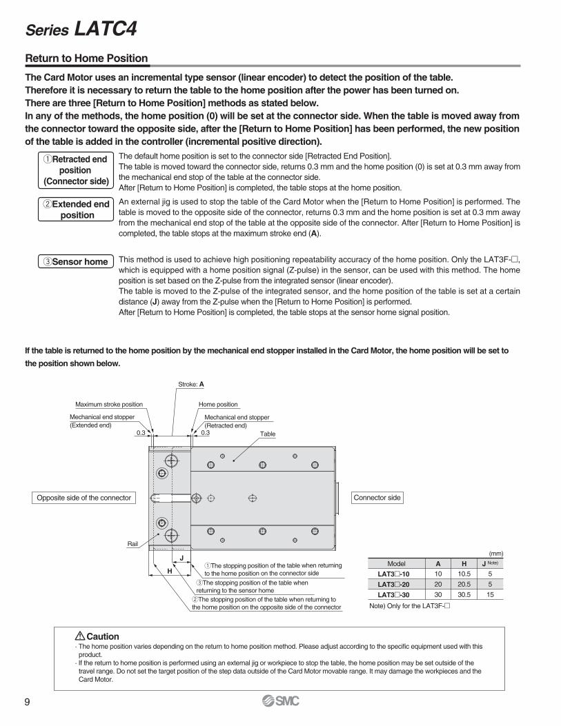
Connector sideOpposite side of the connector
Maximum stroke position
Mechanical end stopper(Extended end)
Stroke: A
Home position
Mechanical end stopper(Retracted end)
0.30.3 Table
Rail
qThe stopping position of the table when returningto the home position on the connector side
eThe stopping position of the table when returning to the sensor home
wThe stopping position of the table when returning tothe home position on the opposite side of the connector
J
H
qRetracted end position
(Connector side)
wExtended endposition
The default home position is set to the connector side [Retracted End Position].The table is moved toward the connector side, returns 0.3 mm and the home position (0) is set at 0.3 mm away from the mechanical end stop of the table at the connector side.After [Return to Home Position] is completed, the table stops at the home position.
An external jig is used to stop the table of the Card Motor when the [Return to Home Position] is performed. Thetable is moved to the opposite side of the connector, returns 0.3 mm and the home position is set at 0.3 mm away from the mechanical end stop of the table at the opposite side of the connector. After [Return to Home Position] is completed, the table stops at the maximum stroke end (A).
eSensor home This method is used to achieve high positioning repeatability accuracy of the home position. Only the LAT3F-m,which is equipped with a home position signal (Z-pulse) in the sensor, can be used with this method. The home position is set based on the Z-pulse from the integrated sensor (linear encoder).The table is moved to the Z-pulse of the integrated sensor, and the home position of the table is set at a certain distance (J) away from the Z-pulse when the [Return to Home Position] is performed.After [Return to Home Position] is completed, the table stops at the sensor home signal position.
The Card Motor uses an incremental type sensor (linear encoder) to detect the position of the table.Therefore it is necessary to return the table to the home position after the power has been turned on.There are three [Return to Home Position] methods as stated below.In any of the methods, the home position (0) will be set at the connector side. When the table is moved away from the connector toward the opposite side, after the [Return to Home Position] has been performed, the new positionof the table is added in the controller (incremental positive direction).
If the table is returned to the home position by the mechanical end stopper installed in the Card Motor, the home position will be set to
the position shown below.
Model A H J Note)
10
20
30
10.5
20.5
30.5
5
5
15
LAT3m-10
LAT3m-20
LAT3m-30
Note) Only for the LAT3F-m
· The home position varies depending on the return to home position method. Please adjust according to the specific equipment used with thisproduct.
· If the return to home position is performed using an external jig or workpiece to stop the table, the home position may be set outside of thetravel range. Do not set the target position of the step data outside of the Card Motor movable range. It may damage the workpieces and theCard Motor.
Caution
(mm)
Return to Home Position
9
Series LATC4
Power supply
Power supply
IN0 to 3
SVON
DRIVE
BUSY
ALARM
Input
Output
Speed
Return to home position
24 V0 V
ONOFF
0 mm/s
ONOFF
IN0 to 3
SVON
DRIVE
BUSY
Input
Output
Power supply
Input
Output
SpeedPositioning operation
ONOFF
0 mm/s
ONOFF
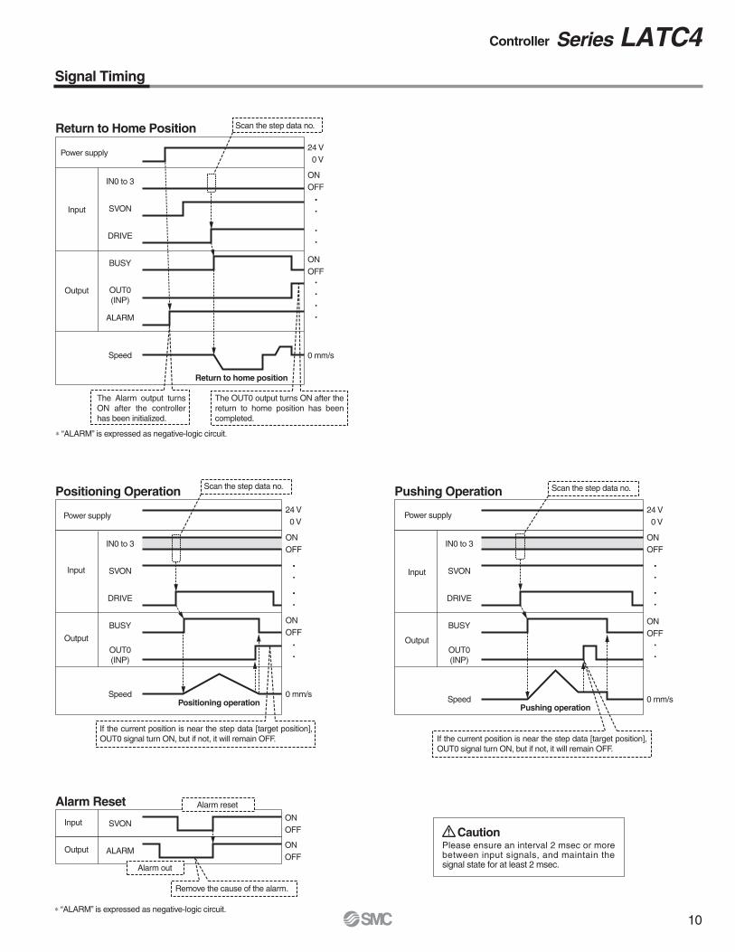
The OUT0 output turns ON after the return to home position has beencompleted.
The Alarm output turnsON after the controller has been initialized.
∗ “ALARM” is expressed as negative-logic circuit.
Scan the step data no.
If the current position is near the step data [target position], OUT0 signal turn ON, but if not, it will remain OFF. If the current position is near the step data [target position],
OUT0 signal turn ON, but if not, it will remain OFF.
IN0 to 3
SVON
DRIVE
BUSY
SpeedPushing operation
ONOFF
0 mm/s
ONOFF
SVON
ALARM
Input
Output
ONOFF
ONOFF
Alarm out
Alarm reset
Remove the cause of the alarm.
OUT0(INP)
OUT0(INP)
OUT0(INP)
24 V0 V
24 V 0 V
∗ “ALARM” is expressed as negative-logic circuit.
Scan the step data no. Scan the step data no.
Please ensure an interval 2 msec or morebetween input signals, and maintain the signal state for at least 2 msec.
Caution
Return to Home Position
Positioning Operation
Alarm Reset
Pushing Operation
10
Signal Timing
Controller Series LATC4
Controller side
Raised area
Actuator side
PLC sideController side
Multi-counter sideController side
A1(Red)
CB
A
Color polarity indication
(Red)
Polarized key
B1A1B1
(Red)
A1(Red)
View C
(25.5)
(18)
(25.5)
(21)
(9)
(ø5.
2)(7)
(10) L
(18.
6)
(6)
(15.
4)
L
Fused
Fused Fused (10)
Fused (10)
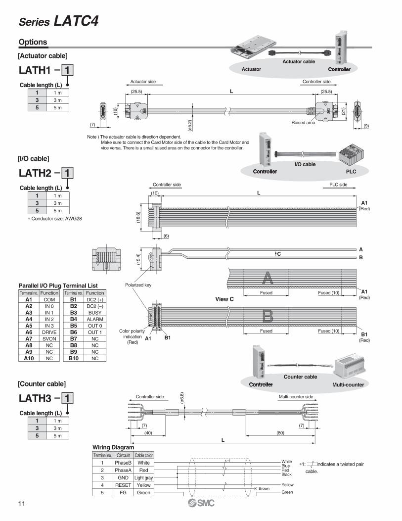
[Actuator cable]
LATH1 1Cable length (L)
135
1 m
3 m
5 m
[I/O cable]
LATH2 1Cable length (L)
135
1 m
3 m
5 m
∗ Conductor size: AWG28
Parallel I/O Plug Terminal List
COMIN 0IN 1IN 2IN 3
DRIVESVON
NCNCNC
FunctionA1A2A3A4A5A6A7A8A9A10
Terminal no.DC2 (+)DC2 (−)BUSY
ALARMOUT 0OUT 1
NCNCNCNC
FunctionB1B2B3B4B5B6B7B8B9B10
Terminal no.
Wiring Diagram
WhiteBlueRedBlack
Yellow
GreenBrown
White
Red
Light gray
Yellow
Green
Cable color
PhaseB
PhaseA
GND
RESET
FG
1
2
3
4
5
Terminal no. Circuit
(7)
(80)
L(40)
(7)
(ø6.
8)
[Counter cable]
LATH3 1Cable length (L)
135
1 m
3 m
5 m
PLCControllerI/O cable
Controller Multi-counter
Counter cable
Options
ControllerActuator
Actuator cable
Note ) The actuator cable is direction dependent.Make sure to connect the Card Motor side of the cable to the Card Motor and vice versa. There is a small raised area on the connector for the controller.
∗1∗1: indicates a twisted pair
cable.
11
Series LATC4
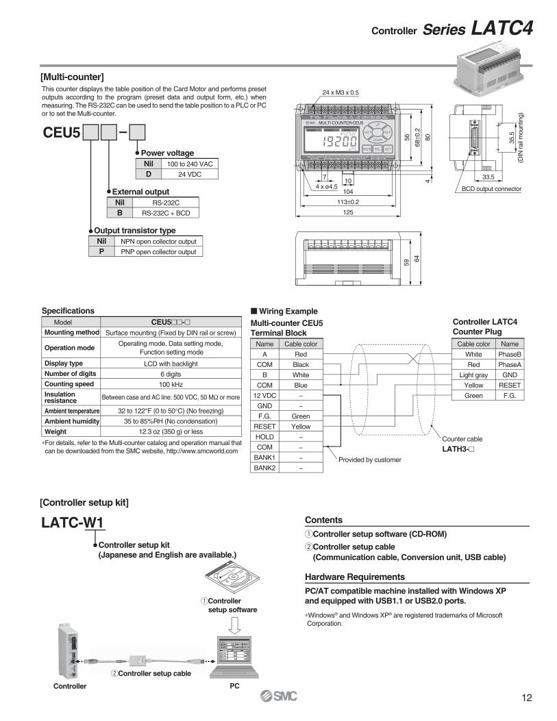
Multi-counter CEU5 Terminal Block
Controller LATC4 Counter Plug
A
COM
B
COM
12 VDC
GND
F.G.
RESET
HOLD
COM
BANK1
BANK2
Name Cable color
Red
Black
White
Blue
−
−
Green
Yellow
−
−
−
−
PhaseB
PhaseA
GND
RESET
F.G.
NameCable color
White
Red
Light gray
Yellow
Green
Provided by customer
Counter cable
LATH3-m
∗Windows® and Windows XP® are registered trademarks of Microsoft Corporation.
LATC-W1
[Multi-counter]
[Controller setup kit]
PCController
wController setup cable
qControllersetup software
qController setup software (CD-ROM)
wController setup cable(Communication cable, Conversion unit, USB cable)
Contents
PC/AT compatible machine installed with Windows XP and equipped with USB1.1 or USB2.0 ports.
Hardware Requirements
CEU5Power voltage
External outputNilB
RS-232C
RS-232C + BCD
NilD
100 to 240 VAC
24 VDC
Output transistor typeNilP
NPN open collector output
PNP open collector output
Controller setup kit(Japanese and English are available.)
BCD output connector
33.5
59
64
35.5
(DIN
rail
mou
ntin
g)
MULTI COUNTER:CEU5A COM COM COMB DC12V GND F.G. R.S. HOLD BANK1 BANK2
COM S.STOPOUT1OUT2OUT3OUT4OUT5AC100~240V
COUNT PRESET FUNC.
SD SGRD RS-232C
UP
LEFT RIGHT
DOWN
SEL. SETMODE
24 x M3 x 0.5
4 x ø4.5104
113±0.2
125
107
56
68±0
.2
804
Specifications
Surface mounting (Fixed by DIN rail or screw)
LCD with backlight
6 digits
100 kHz
Between case and AC line: 500 VDC, 50 MΩ or more
32 to 122°F (0 to 50°C) (No freezing)
35 to 85%RH (No condensation)
12.3 oz (350 g) or less
Operating mode, Data setting mode, Function setting mode
CEU5mm-mMounting method
Operation mode
Display type
Number of digits
Counting speed
Insulationresistance
Ambient temperature
Ambient humidity
Weight
Model
M Wiring Example
∗For details, refer to the Multi-counter catalog and operation manual that can be downloaded from the SMC website, http://www.smcworld.com
This counter displays the table position of the Card Motor and performs preset outputs according to the program (preset data and output form, etc.) when measuring. The RS-232C can be used to send the table position to a PLC or PCor to set the Multi-counter.
12
Controller Series LATC4
Series LAT3Specific Product Precautions 1Be sure to read before handling. Refer to back cover for Safety Instructions. For Electric Actuator Precautions, refer to “Handling Precautions for SMC Products” (M-E03-3) and Operation Manual. Please download it via our website, http://www.smcworld.com
Design/Selection
Warning1. Consider possible movements of the actuator in the event of
an emergency stop, alarm or power failure.If power is not supplied to the product due to an emergency stop or if the SVON signal is turned OFF, in the event of an alarm (when temperature of the Card Motor exceeds 158°F (70°C)) or at power failure, the table will not be held in place and may be moved by external forces. Design the Card Motor application so that people and equipment will not be injured or damaged by the table movement.
Caution1. Do not apply a load outside the specifications.
The Card Motor should be fitted for the application based on themaximum workload and allowable moments. If the product is usedoutside the specifications, the excess load applied to the guide will lead to play in the guide, decrease in accuracy and the life span of the product will be shortened.
2. Do not use the product in applications where excessive external force or impact is applied to it.Otherwise, a failure or malfunction can result.
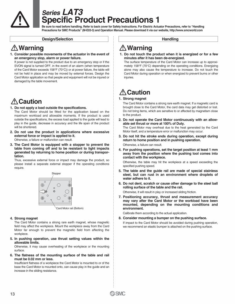
3. The Card Motor is equipped with a stopper to prevent the table from coming off and to be resistant to light impacts generated by returning to home position or during transpor-tation.Thus, excessive external force or impact may damage the product, so please install a separate external stopper if the operating conditionsrequire.
4. Strong magnetThe Card Motor contains a strong rare earth magnet, whose magnetic field may affect the workpiece. Mount the workpiece away from the Card Motor far enough to prevent the magnetic field from affecting theworkpiece.
5. In pushing operation, use thrust setting values within the allowable limits.Otherwise, it may cause overheating of the workpiece or the mounting surface.
6. The flatness of the mounting surface of the table and rail must be 0.02 mm or less.Insufficient flatness of a workpiece the Card Motor is mounted to or of the base the Card Motor is mounted onto, can cause play in the guide and an increase in the sliding resistance.
Handling
Warning1. Do not touch the product when it is energized or for a few
minutes after it has been de-energized.The surface temperature of the Card Motor can increase up to approxi-mately 158°F (70°C) depending on the operating conditions. Energizing alone may also cause the temperature to increase. Do not touch the Card Motor during operation or when energized to prevent burns or other injuries.
Caution1. Strong magnet
The Card Motor contains a strong rare earth magnet. If a magnetic card is brought close to the Card Motor, the card data may get distorted or lost. Do not bring items, which are sensitive to or affected by magnetism close to the product.
2. Do not operate the Card Motor continuously with an allow-able set thrust or more at 100% of Duty.The Card Motor may overheat due to the heat generated by the Card Motor itself, and a temperature error or malfunction may occur.
3. Do not hit the stroke ends during operation, except during return to home position and in pushing operation.Otherwise, a failure can result.
4. For pushing operations, set the target position at least 1 mm away from the position where the pushing tool comes into contact with the workpiece.Otherwise, the table may hit the workpiece at a speed exceeding thespecified pushing speed.
5. The table and the guide rail are made of special stainless steel, but can rust in an environment where droplets ofwater adhere to it.
6. Do not dent, scratch or cause other damage to the steel ball rolling surface of the table and the rail.Otherwise, it will result in play or increased sliding friction.
7. Positioning accuracy, thrust and measurement accuracy may vary after the Card Motor or the workload have been mounted, depending on the mounting conditions andenvironment.Calibrate them according to the actual application.
8. Consider mounting a bumper on the pushing surface.If impact to the Card Motor should be avoided during pushing operation, we recommend an elastic bumper is attached on the pushing surface.
Stopper
Card Motor rail (Bottom)
13
L1 L2L4L3
L5
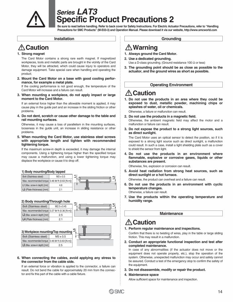
Bolt (Stainless steel)
Max. recommended torque
L1 (Max. screw-in depth) [mm]
L2 (Plate thickness) [mm]
M3 x 0.5
0.46 lbf ft (0.63 [N·m])
4.6
2.1
1) Body mounting/Body tapped
Bolt (Stainless steel)
Max. recommended torque
L3 (Max. screw-in depth) [mm]
L4 (Plate thickness) [mm]
M2.5 x 0.45
0.27 lbf ft (0.36 [N·m])
2.5
2.1
2) Body mounting/Through hole
Bolt (Stainless steel)
Max. recommended torque
L5 (Max. screw-in depth) [mm]
M3 x 0.5
0.46 lbf ft (0.63 [N·m])
2.5
3) Workpiece mounting/Top mounting
Operating Environment
Caution1. Do not use the products in an area where they could be
exposed to dust, metallic powder, machining chips orsplashes of water, oil or chemicals.Otherwise, a failure or malfunction can result.
2. Do not use the products in a magnetic field.Otherwise, the ambient magnetic field may affect the motor and amalfunction or failure can result.
3. Do not expose the product to a strong light sources, such as direct sunlight.The Card Motor uses an optical sensor to detect the position, so if it is exposed to a strong light source such as direct sunlight, a malfunctioncould result. In such a case, install a light shielding plate such as a cover to shield the sensor from light.
4. Do not use the products in an environment where flammable, explosive or corrosive gases, liquids or other substances are present.Otherwise, fire, explosion or corrosion can result.
5. Avoid heat radiation from strong heat sources, such asdirect sunlight or a hot furnace.Otherwise, the product can overheat and a failure can result.
6. Do not use the products in an environment with cyclic temperature changes.Otherwise, a failure can result.
7. Use the products within the operating temperature andhumidity range.
Maintenance
Caution1. Perform regular maintenance and inspections.
Confirm that there is no twisting of wires, play in the table or large sliding friction. This may result in a malfunction.
2. Conduct an appropriate functional inspection and test after completed maintenance.In case of any abnormalities (if the actuator does not move or theequipment does not operate properly, etc.), stop the operation of the system. Otherwise, unexpected malfunction may occur and safety cannot be assured. Conduct a test of the emergency stop to confirm the safety of the equipment.
3. Do not disassemble, modify or repair the product.4. Maintenance space
Allow sufficient space for maintenance and inspection.
Grounding
Warning1. Always ground the Card Motor.2. Use a dedicated grounding.
Use a D-class grounding. (Ground resistance 100 Ω or less)
3. The grounding point should be as close as possible to the actuator, and the ground wires as short as possible.
Installation
Caution1. Strong magnet
The Card Motor contains a strong rare earth magnet. If magnetizedworkpieces, tools and metallic parts are brought in the vicinity of the Card Motor, they will be attracted, which could cause injury to operators and damage equipment. Take special care when handling and operating the product.
2. Mount the Card Motor on a base with good cooling perfor-mance, for example a metal plate.If the cooling performance is not good enough, the temperature of the Card Motor will increase and a failure can result.
3. When mounting a workpiece, do not apply impact or large moment to the Card Motor.If an external force higher than the allowable moment is applied, it may cause play in the guide part and an increase in the sliding friction or other problems.
4. Do not dent, scratch or cause other damage to the table and rail mounting surfaces.Otherwise, it may cause a loss of parallelism in the mounting surfaces, looseness in the guide unit, an increase in sliding resistance or other problems.
5. When mounting the Card Motor, use stainless steel screws with appropriate length and tighten with recommended tightening torque.If the maximum screw-in depth is exceeded, it may damage the internal components. Using a tightening torque higher than the specified torque may cause a malfunction, and using a lower tightening torque maydisplace the workpiece or cause it to drop off.
6. When connecting the cables, avoid applying any stress to the connector from the cable side.If an external force or vibration is applied to the connector, a failure can result. Do not bend the cable for approximately 20 mm from the connec-tor and fix this part of the cable with a cable fixture.
Series LAT3Specific Product Precautions 2Be sure to read before handling. Refer to back cover for Safety Instructions. For Electric Actuator Precautions, refer to “Handling Precautions for SMC Products” (M-E03-3) and Operation Manual. Please download it via our website, http://www.smcworld.com
14

Design/Selection Handling
Warning1. Use the specified voltage.
If the applied voltage is higher than the specified voltage, malfunction and damage to the controller may result. If the applied voltage is lower than the specified voltage, there is a possibility that the load cannot be moved due to internal voltage drop. Check the operating voltage prior to start. Also, confirm that the operating voltage does not drop below the specified voltage during operation.If the current is too low, the Card Motor may not be able to generate the maximum force or cause a malfunction.
2. Do not use the products outside the specifications.Otherwise, fire, malfunction or damage to the product can result. Check the specifications prior to use.
3. Install an emergency stop circuit.Install an emergency stop outside the enclosure in easy reach to the operator so that the operator can stop the system operation immediately and intercept the power supply.
4. To prevent danger and damage due to a breakdown ormalfunction of these products, which may occur at a certain probability, a backup system should be arranged in advanceby using a multiple-layered structure or by making a fail-safe equipment design, etc.
5. If there is a risk of fire or personal injury due to abnormal heat generation, sparking, smoke generated by the product, etc., cut off the power supply from this product and thesystem immediately.
Handling
Warning1. Never touch the inside of the controller and its peripheral
devices.Otherwise, electric shock or failure can result.
2. Do not operate or set up this equipment with wet hands.Otherwise, electric shock can result.
3. Do not use a product that is damaged or missing anycomponents.Electric shock, fire or injury can result.
4. Do not connect the controller to other devices than the Card Motor.Otherwise, it may cause damage to the controller or to the other equipment.
5. Be careful not to touch, get caught or hit by the workpiece while the Card Motor is moving.An injury can result.
6. Do not connect the power supply or power up the productuntil it is confirmed that the workpiece can be moved safelywithin the area that can be reached by the workpiece.Otherwise, the movement of the workpiece may cause an accident.
7. Do not touch the product when it is energized and for sometime after the power has been disconnected, as it is very hot.Otherwise, it may cause burns due to the high temperature.
8. Check the voltage using a tester at least 5 minutes after power-off when performing installation, wiring and mainte-nance.Otherwise, electric shock, fire or injury can result.
9. Static electricity may cause a malfunction or damage the controller. Do not touch the controller while power issupplied to it.Take sufficient safety measures to eliminate static electricity when it is necessary to touch the controller for maintenance.
Caution1. When the Multi-counter is not used, attach the counter plug
to the counter connector of the controller.If foreign matter such as metal fragments enters the counter connector, short-circuit may occur.
2. Be sure to perform return to home position prior to start.If the home position is not set, the product will not operate even if the step data is performed.
3. The positioning time entered and set in the controller setup software is just a target value. It cannot be guaranteed.The operation may not have been completed even if the set positioning time has passed. In such a case, the BUSY and INP digital output signals can be used to detect when the operation has been completed.
4. Set the “Load Mass” value in the controller setup software according to the approximate weight of jigs or workpieces mounted on the Card Motor.If the “Load Mass” value in the controller setup software and the weight of the workload are different, the product may vibrate or the positioning accuracy may be reduced.
5. When the load mounted on the Card Motor is small (such as 100 g or less) and the Card Motor has stopped at a target position, depending on the operating conditions the Card Motor may continuously hunt for the target position (vibrate) within the positioning accuracy range.Please contact an SMC Sales representative for how to improve it.
6. BUSY signalThe BUSY signal turns ON when the Card Motor begins to operate, and it turns OFF when the operating speed reaches 2 mm/s or less. However, when the Card Motor operates at a slower speed than 5 mm/s, the BUSY signal may not turn ON at all.
7. INP output signal (OUT0)Both in positioning operation and pushing operation, the INP signal will turn ON when the table has reached within the INP output range of the target position.In pushing operation, if the tableexceeds the target position andmoves outside the INP output range, the INP signal will turn OFF again.
ModelLAT3F-mLAT3-m
Output range (mm)±0.05±0.3
Output range of the INP signal (OUT0)
Mounting
Warning1. Install the controller and its peripheral devices on fireproof
material.Direct installation on or near flammable material may cause fire.
2. Do not install these products in a place subject to vibration and impact.Otherwise, a malfunction or failure can result.
3. Do not mount the controller and its peripheral devices on the same base together with a large-sized electromagnetic contactor or no-fuse breaker that generate vibration. Mount them ondifferent base plates, or keep the controller and its peripheral devices away from such vibration supplies.Otherwise, a malfunction can result.
4. Install the controller and its peripheral devices on a flat surface.If the mounting surface is not flat or uneven, excessive force may be applied to the housing and other parts resulting in a malfunction.
Power Supply
Warning1. Use a power supply with low noise between lines and
between power and ground.In cases where noise is high, use an isolation transformer.
2. The power supplies should be separated between the control-ler power and the I/O signal power, and both power supplies must not be of “inrush-current limited” type.If the power supply is of “inrush-current limited” type, a voltage drop may occur during the acceleration or deceleration of the actuator.
Series LAT3 Controller and Peripheral Devices/Specific Product Precautions 1Be sure to read before handling. Refer to back cover for Safety Instructions. For Electric Actuator Precautions, refer to “Handling Precautions for SMC Products” (M-E03-3) and Operation Manual. Please download it via our website, http://www.smcworld.com
15

Grounding
Maintenance
Warning
Warning
1. Make sure the product is grounded to ensure the noisetolerance of the controller.Otherwise, it may cause a malfunction, damage, electric shock or fire. Do not share the earth with devices or equipment that generates a strong electromagnetic noise.
2. Use a dedicated grounding.Use a D-class grounding. (Ground resistance 100 Ω or less)
3. The grounding point should be as close as possible to the controller, and the ground wires as short as possible.
4. In the unlikely event that malfunction is caused by theground, it may be disconnected.
1. Perform maintenance checks periodically.Confirm wiring and screws are not loose. Loose screws or wires may cause unexpected malfunction.
2. Conduct an appropriate functional inspection and test after completed maintenance.In case of any abnormalities (if the actuator does not move or theequipment does not operate properly, etc.), stop the operation of the system. Otherwise, unexpected malfunction may occur and safety cannot be assured. Conduct a test of the emergency stop to confirm the safety of the equipment.
3. Do not disassemble, modify or repair the controller or its peripheral devices.
4. Do not put anything conductive or flammable inside thecontroller.Otherwise, fire can result.
5. Do not conduct an insulation resistance test or insulation withstand voltage test.
Wiring
Warning1. Preparation for wiring
Turn the power supply off before wiring or plugging and unplugging of connectors. Mount a protective cover on the terminal block after the wireshave been connected.
2. Do not route the digital I/O signal and power cablestogether.Malfunctions stemming from noise may occur if the signal line and outputlines are routed together.
3. Confirm proper wiring before turning the power on.Incorrect wiring will lead to malfunction or may damage the controller or its peripheral devices. Confirm that there is no mis-wiring before turningthe power on.
4. Reserve enough space for the routing of the cablesIf the cables are forced into unreasonable positions, it may damage the cables and connectors, which may lead to misconnection and result in a malfunction. Avoid bending the cables in sharp angles close to theconnectors or where they enter the product. Fix the cable as close aspossible to the connectors so that mechanical stress cannot be applied to the connectors.
Operating Environment
Caution1. Do not use the products in an area where they could be
exposed to dust, metallic powder, machining chips orsplashes of water, oil or chemicals.Otherwise, a failure or malfunction can result.
2. Do not use the products in a magnetic field.Otherwise, a malfunction or failure can result.
3. Do not use the products in an environment where flammable, explosive or corrosive gases, liquids or other substances are present.Otherwise, fire, explosion or corrosion can result.
4. Avoid heat radiation from strong heat sources, such asdirect sunlight or a hot furnace.Otherwise, it will cause a failure to the controller or its peripheral devices.
5. Do not use the products in an environment with cyclic temperature changes.Otherwise, it will cause a failure to the controller or its peripheral devices.
6. Do not use the products in an environment where surges are generated.Devices (solenoid type lifters, high frequency induction furnaces, motors,etc.) that generate a large amount of surge around the product may lead to deterioration or damage to the internal circuits of the products. Avoid supplies of surge generation and crossed lines.
7. The Card Motor and the controller are not immune tolightning strikes.
8. Do not install these products in a place subject to vibration and impact.Otherwise, a malfunction or failure can result.
Caution1. Reserve sufficient space for maintenance.
Design the system so that it allows required space for maintenance.
Power Supply
Warning3. Take appropriate measures to prevent surges from
lightning. Ground the surge absorber for lightning separately from the grounding of the controller and itsperipheral devices.
4. Use the UL-certified products listed below as direct current power supplies.(1) Limited voltage current circuit in accordance with UL 508.
A circuit in which power is supplied by secondary coil of an insulated transformer that meets the following conditions· Maximum voltage (No load): 30 Vrms (42.4 V peak) or less· Maximum current : q 8 A or less (including short circuit)
w Limited by a circuit protector (such as a fuse) with the
following ratings
(2) Circuit (of class 2) which is of maximum 30 Vrms (42.4 V peak) or less, with UL 1310 class 2 power supply unit or UL 1585 class 2 transformer.
Voltage without load (V peak)
0 to 20 [V]
Over 20 [V] up to 30 [V]
Maximum current rating
5.0
100Peak voltage
Series LAT3 Controller and Peripheral Devices/Specific Product Precautions 2Be sure to read before handling. Refer to back cover for Safety Instructions. For Electric Actuator Precautions, refer to “Handling Precautions for SMC Products” (M-E03-3) and Operation Manual. Please download it via our website, http://www.smcworld.com
16
Safety Instructions Be sure to read “Handling Precautions for SMC Products” (M-E03-3) before using.
1. The compatibility of the product is the responsibility of theperson who designs the equipment or decides its specifications.Since the product specified here is used under various operating conditions, its compatibility with specific equipment must be decided by the person who designs the equipment or decides its specifications based on necessary analysis and test results. The expected performance and safety assurance of the equipment will be the responsibility of the person who has determined its compatibility with the product. This person should also continuously review all specifications of the product referring to its latest catalog information, with a view to giving dueconsideration to any possibility of equipment failure when configuring theequipment.
2. Only personnel with appropriate training should operate machinery and equipment.The product specified here may become unsafe if handled incorrectly. Theassembly, operation and maintenance of machines or equipment including our products must be performed by an operator who is appropriately trained and experienced.
3. Do not service or attempt to remove product andmachinery/equipment until safety is confirmed.1. The inspection and maintenance of machinery/equipment should only be
performed after measures to prevent falling or runaway of the driven objects have been confirmed.
2. When the product is to be removed, confirm that the safety measures as mentioned above are implemented and the power from any appropriate source is cut, and read and understand the specific product precautions of all relevant products carefully.
3. Before machinery/equipment is restarted, take measures to preventunexpected operation and malfunction.
4. Contact SMC beforehand and take special consideration of safety measures if the product is to be used in any of the following conditions.1. Conditions and environments outside of the given specifications, or use
outdoors or in a place exposed to direct sunlight.2. Installation on equipment in conjunction with atomic energy, railways, air
navigation, space, shipping, vehicles, military, medical treatment, combustion and recreation, or equipment in contact with food and beverages, emergency stop circuits, clutch and brake circuits in press applications, safety equipment or other applications unsuitable for the standard specifications described in the product catalog.
3. An application which could have negative effects on people, property, oranimals requiring special safety analysis.
4. Use in an interlock circuit, which requires the provision of double interlock forpossible failure by using a mechanical protective function, and periodicalchecks to confirm proper operation.
Warning
Limited warranty and Disclaimer/Compliance Requirements The product used is subject to the following “Limited warranty and Disclaimer” and “Compliance Requirements”.Read and accept them before using the product.
1. The product is provided for use in manufacturing industries.The product herein described is basically provided for peaceful use inmanufacturing industries. If considering using the product in other industries, consult SMC beforehand and exchange specifications or a contract if necessary. If anything is unclear, contact your nearest sales branch.
Caution
Limited warranty and Disclaimer1. The warranty period of the product is 1 year in service or 1.5 years after the
product is delivered.∗2)
Also, the product may have specified durability, running distance orreplacement parts. Please consult your nearest sales branch.
2. For any failure or damage reported within the warranty period which is clearly our responsibility, a replacement product or necessary parts will be provided. This limited warranty applies only to our product independently, and not to any other damage incurred due to the failure of the product.
3. Prior to using SMC products, please read and understand the warranty terms and disclaimers noted in the specified catalog for the particular products.
∗2) Vacuum pads are excluded from this 1 year warranty.A vacuum pad is a consumable part, so it is warranted for a year after it is delivered. Also, even within the warranty period, the wear of a product due to the use of the vacuum pad orfailure due to the deterioration of rubber material are not covered by the limited warranty.
Compliance Requirements1. The use of SMC products with production equipment for the manufacture of weapons of
mass destruction (WMD) or any other weapon is strictly prohibited.
2. The exports of SMC products or technology from one country to another are governed by the relevant security laws and regulations of the countries involved in thetransaction. Prior to the shipment of a SMC product to another country, assure that all local rules governing that export are known and followed.
These safety instructions are intended to prevent hazardous situations and/or equipment damage. These instructions indicate the level of potential hazard with the labels of “Caution,” “Warning” or “Danger.” They are all important notes for safety and must be followed in addition to International Standards (ISO/IEC)∗1), and other safetyregulations.
∗1) ISO 4414: Pneumatic fluid power – General rules relating to systems. ISO 4413: Hydraulic fluid power – General rules relating to systems. IEC 60204-1: Safety of machinery – Electrical equipment of machines. (Part 1: General requirements) ISO 10218-1: Manipulating industrial robots - Safety. etc.
Caution indicates a hazard with a low level of risk which, if not avoided, could result in minor or moderate injury.
Warning indicates a hazard with a medium level of risk which, if not avoided, could result in death or serious injury.
Caution:
Warning:
Danger :Danger indicates a hazard with a high level of riskwhich, if not avoided, will result in death or seriousinjury.
Safety Instructions
SMC Corporation of America10100 SMC Blvd., Noblesville, IN 46060 www.smcusa.comSMC Pneumatics (Canada) Ltd.www.smcpneumatics.ca
(800) SMC.SMC1 (762-7621)e-mail: [email protected] International inquiries: www.smcworld.com
© 2012 SMC Corporation of America, All Rights Reserved.
All reasonable efforts to ensure the accuracy of the information detailed in this catalog were made at the time of publishing. However, SMC can in no way warrant the information herein contained as specifications are subject to change without notice.QS-PP-5M


![Transportation Problem - ULisboaweb.tecnico.ulisboa.pt/~mcasquilho/CD_Casquilho/TP_PrototypeAnd… · example in Hillier & Lieberman [2006, pp 330–331]4. EXAMPLE Table 3 — Production](https://img.pdfslide.us/doc/110x75/5ea9f3dd37d31403e3081443/transportation-problem-mcasquilhocdcasquilhotpprototypeand-example-in-hillier.jpg)