Embed Size (px)
Citation preview

PRODUCT MANUAL
© Dionex Corporation, 2004Document No. 031992
Revision 0106 April 2004
for theCARBOPAC PA200 Guard Column
(3 x 50 mm, P/N 062895)
CARBOPAC PA200 Analytical Column(3 x 250 mm, P/N 062896)
QUICKSTART STEPS AND LINKSClick blue text below to get started.
1. See Section 4, “Before You Start” and Section 5, “Preparation of Eluents andStandards.” Note general operating conditions, precautions and chemical purityrequirements. Make the required solutions and eluents.
2. See Section 8, "Example Applications" for example applications.
3. See Appendix A, “Quality Assurance Reports”. Run the Production TestChromatogram as a system check.

CarboPac PA200 Document No. 031992-01 Page 2 of 41
TABLE OF CONTENTS
SECTION 1 - INTRODUCTION ........................................................................................................ 5
1.1 CarboPac PA200 ...................................................................................................................................................... 5
1.2 Disposable Gold Working Electrodes .................................................................................................................... 5
1.3 BioLC Carbohydrate System (Without Columns) ............................................................................................... 6
1.4 Electrochemical Gold Cells ..................................................................................................................................... 6
1.5 Guard Column Use .................................................................................................................................................. 6
1.6 CarboPac PA200 Anion Exchange Columns ........................................................................................................ 6
SECTION 2 – OPERATION AND SYSTEM REQUIREMENTS ................................................. 7
2.1 System Requirements .............................................................................................................................................. 7
2.2 System Operation Requirements ........................................................................................................................... 7
2.3 CarboPac PA200 Column Operational Parameters ............................................................................................ 7
SECTION 3 – PURITY REQUIREMENTS FOR CHEMICALS .................................................. 8
3.1 Deionized Water ....................................................................................................................................................... 8
3.2 Sodium Hydroxide ................................................................................................................................................... 8
3.3 Sodium Acetate ........................................................................................................................................................ 8
SECTION 4 – BEFORE YOU START ............................................................................................... 9
4.1 The Most Important Rules ..................................................................................................................................... 9
4.2 Initial Check List ..................................................................................................................................................... 9
SECTION 5 – PREPARATION OF ELUENTS AND STANDARDS ........................................... 10
5.1 Eluent E1: Deionized Water ................................................................................................................................. 10
5.2 Eluent E2: 200 mMSodium Hydroxide .............................................................................................................. 10
5.3 Eluent E3: 100 mM Sodium Hydroxide ............................................................................................................... 11
5.4 Eluent E4: 100 mM Sodium Hydroxide/ 1 M Sodium Acetate .......................................................................... 11
5.5 Carbohydrate Sialylated N-linked Alditol Standard ......................................................................................... 12

CarboPac PA200 Document No. 031992-01 Page 3 of 41
SECTION 6 – GETTING STARTED ............................................................................................... 13
6.1 Introduction To The Detection Methods ............................................................................................................. 13
6.2 Sample Preparation ............................................................................................................................................... 14
SECTION 7 – INSTALLATION AND STARTUP .......................................................................... 15
7.1 System Configuration and Startup ...................................................................................................................... 157.1.1 AS50 Thermal Compartment Modification for 2-mm Operation ............................................................................ 157.1.2 Installation of Disposable Electrodes ...................................................................................................................... 167.1.3 System Rinse ............................................................................................................................................................ 17
7.2 Verification Of System Cleanliness ...................................................................................................................... 177.2.1. System Background Check ...................................................................................................................................... 177.2.2 Verification of Column Cleanliness ......................................................................................................................... 17
SECTION 8 – APPLICATIONS........................................................................................................ 18
8.1 Glycoprotein Characterization and Quality Control ........................................................................................ 188.1.1 Fetuin Oligosaccharide Alditol Profiling ................................................................................................................. 198.1.2 Antibodies Separations ............................................................................................................................................ 20
8.2 Profiling of Complex Plant Carbohydrates ........................................................................................................ 228.2.1 Profiling of Inulins ................................................................................................................................................... 228.2.2 Amylopectins ........................................................................................................................................................... 23
8.3 Sialyl Lactose (N-Acetylneuraminyl-Lactose) .................................................................................................... 24
8.4 Separation of Mannose 7 D1, D3 Isomers ........................................................................................................... 25
8.5 Separation of Neutral N-Linked Oligosaccharides ............................................................................................ 268.5.1 Complex Neutral Structures ..................................................................................................................................... 268.5.2 High Mannose Structures ......................................................................................................................................... 27
8.6 HPAE-PAD Oligosaccharide Resources .............................................................................................................. 288.6.1 Basic HPAE-PAD Resources - Dionex Applications ............................................................................................... 288.6.2 HPAE-PAD Oligosaccharide Resources .................................................................................................................. 28
SECTION 9 – TROUBLESHOOTING GUIDE ............................................................................. 29
9.1 High Background ................................................................................................................................................... 29
9.2 Decreased Detection Sensitivity ........................................................................................................................... 29
9.3 Column Problems .................................................................................................................................................. 309.3.1 Column Set Causing High Background ................................................................................................................... 309.3.2 Excessive Gradient Rise .......................................................................................................................................... 309.3.3 Peak Efficiency and Resolution are Decreasing ...................................................................................................... 30
9.4 System Problems .................................................................................................................................................... 319.4.1 High Detection Background Caused by the System ................................................................................................ 319.4.2 No Peaks, Poor Peak Area Reproducibility or too Small Peak Areas ...................................................................... 319.4.3 Large Baseline Dip in the Chromatogram................................................................................................................ 31

CarboPac PA200 Document No. 031992-01 Page 4 of 41
9.4.4 Incorrect or Variable Retention Times ..................................................................................................................... 319.4.5 Unidentified Peaks Appear with Expected Analyte Peaks ....................................................................................... 32
9.5 Sodium Hydroxide Cleanup ................................................................................................................................. 32
9.6 Nitric Acid Cleanup ............................................................................................................................................... 32
9.7 Reconditioning of Gold Electrodes ...................................................................................................................... 349.7.1 Mechanical Polishing ............................................................................................................................................... 349.7.2 Sanding of Receded Gold Working Electrodes ........................................................................................................ 349.7.3 Chemical Reconditioning of Gold Working Electrodes ........................................................................................... 34
9.8 Failed Reference Electrode ................................................................................................................................... 35
SECTION 10 – INSTALLING A REFERENCE ELECTRODE .................................................. 36
10.1 What Has Changed ............................................................................................................................................... 36
10.2 What Is Needed ...................................................................................................................................................... 36
10.3 Installation Procedure ........................................................................................................................................... 36
SECTION 11 – WAVEFORMS FOR CARBOHYDRATE ANALYSIS ....................................... 39
APPENDIX A - QUALITY ASSURANCE REPORT ..................................................................... 41

CarboPac PA200 Document No. 031992-01 Page 5 of 41
SECTION 1 - INTRODUCTION
1.1 CarboPac PA200
The CarboPac PA200 column is the latest addition to the CarboPac family of columns for carbohydrate separations. This columnhas been specially developed to provide high resolution separations of charged and neutral oligosaccharides and is therecommended column for these applications. The CarboPac PA200 columns are packed with a hydrophobic, polymeric, pellicularanion exchange resin stable over the range of pH 0–14. This unique pH-stability of the packing material allows the use of eluentcompositions that are conducive to anodic oxidation of carbohydrates at gold electrodes.
Resin Characteristics:Particle Size: 5.5 µmPore Size: microporous (< 10 Å)Cross-linking: 55%Ion exchange capacity: 35 µeq per columnLatex Characteristics:Functional Group: quaternary ammonium ionLatex Diameter: 43 nmLatex Cross-linking: 6%
Typical Operating Parameters:pH range: 0–14Temperature Limit: 4–60 °CPressure Limit: 3500 psiOrganic Solvent Limit: 100% compatibleTypical eluents: High purity water (18.2 megohm-cm), sodium hydroxide, sodium acetate
1.2 Disposable Gold Working Electrodes
Carbohydrates separated by high pH anion exchange chromatography are detected by pulsed amperometric detection and the signalis reported in coulombs (C). Amperometric detection is used to measure the current or charge resulting from oxidation or reductionof analyte molecules at the surface of a working electrode. During oxidation reactions electrons are transferred from moleculesof electroactive analytes, such as carbohydrates, to the working electrode in the amperometry cell. Detection is sensitive and highlyselective for electroactive species, since many potentially interfering species cannot be oxidized or reduced, and are not detected.When a single potential is applied to the working electrode, the detection method is d.c. amperometry. Pulsed amperometry andintegrated amperometry employ a repeating sequence of potentials. Pulsed amperometric detection at a gold working electrodeis a reproducible and sensitive method for all carbohydrates of molecular weight up to ten thousand.
Although carbohydrates can be oxidized at a gold working electrode, the products of the oxidation reaction poison the surface ofthe electrode, inhibiting further analyte oxidation. By repeatedly pulsing between high positive and negative potentials, a stableand active electrode surface can be maintained. However, the gold working electrode is very slowly consumed during this processand will eventually need to be replaced. Occasionally the electrode may be ‘poisoned’ by other contaminants, resulting in asignificantly reduced response. When this occurs, the active surface can be renewed by polishing the electrode. However, this canbe a tedious and time-consuming process.
The Dionex disposable gold electrodes (P/N 060139 for 6, P/N 060216 for 4 packages of 6) make electrode reconditioning bypolishing and other methods superfluous. They are less expensive and can thus be replaced more often than the conventionalelectrodes. The more frequent replacement of working electrodes renders electrochemical detection more predictable andreproducible. The disposable electrodes also make easier any troubleshooting of electrochemical detection problems. The goldhydroxide (AuOH) catalyzed mode of oxidation of carbohydrates differs from the gold oxide catalyzed oxidation of amino acidsat higher potentials. Although both gold electrodes can be mounted in the same ED50 detection cell, and thus in principle it isfeasible to convert a gold electrode from one mode of detection to another, in practice this may require an extensive period of timeand is thus not recommended. The Au electrodes for carbohydrate analysis have been tested for and are guaranteed to work forcarbohydrate analyses.
CarboPac PA200 Document No. 031992-01 Page 6 of 41
NOTEDionex Technical Note 21 Waveform A MUST BE USED with disposable electrodes. Waveform B and WaveformC CANNOT BE USED with Disposable Electrodes. Waveforms B and C will strip the gold surface of thedisposable electrode within 24 hours
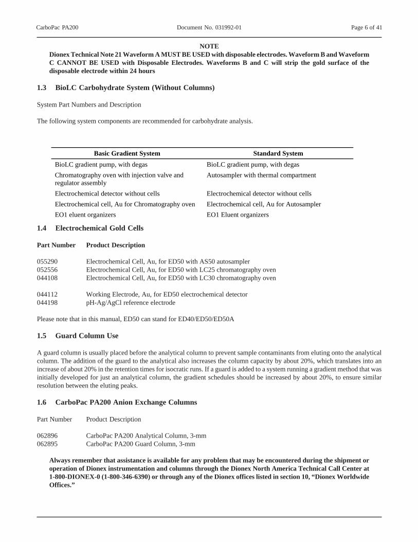
1.3 BioLC Carbohydrate System (Without Columns)
System Part Numbers and Description
The following system components are recommended for carbohydrate analysis.
1.4 Electrochemical Gold Cells
Part Number Product Description
055290 Electrochemical Cell, Au, for ED50 with AS50 autosampler052556 Electrochemical Cell, Au, for ED50 with LC25 chromatography oven044108 Electrochemical Cell, Au, for ED50 with LC30 chromatography oven
044112 Working Electrode, Au, for ED50 electrochemical detector044198 pH-Ag/AgCl reference electrode
Please note that in this manual, ED50 can stand for ED40/ED50/ED50A
1.5 Guard Column Use
A guard column is usually placed before the analytical column to prevent sample contaminants from eluting onto the analyticalcolumn. The addition of the guard to the analytical also increases the column capacity by about 20%, which translates into anincrease of about 20% in the retention times for isocratic runs. If a guard is added to a system running a gradient method that wasinitially developed for just an analytical column, the gradient schedules should be increased by about 20%, to ensure similarresolution between the eluting peaks.
1.6 CarboPac PA200 Anion Exchange Columns
Part Number Product Description
062896 CarboPac PA200 Analytical Column, 3-mm062895 CarboPac PA200 Guard Column, 3-mm
Always remember that assistance is available for any problem that may be encountered during the shipment oroperation of Dionex instrumentation and columns through the Dionex North America Technical Call Center at1-800-DIONEX-0 (1-800-346-6390) or through any of the Dionex offices listed in section 10, “Dionex WorldwideOffices.”
Basic Gradient System Standard System BioLC gradient pump, with degas BioLC gradient pump, with degas Chromatography oven with injection valve and regulator assembly
Autosampler with thermal compartment
Electrochemical detector without cells Electrochemical detector without cells Electrochemical cell, Au for Chromatography oven Electrochemical cell, Au for Autosampler EO1 eluent organizers EO1 Eluent organizers

CarboPac PA200 Document No. 031992-01 Page 7 of 41
SECTION 2 – OPERATION AND SYSTEM REQUIREMENTS
2.1 System Requirements
The carbohydrate separations with the CarboPac PA200 columns are optimized for use with Dionex 2-mm systems, whether theyare the 2-mm Dionex DX 500, DX 600 or BioLC. The pump should be configured for microbore pumping (microbore pump heads,pump heads volume 25 µL). All of these systems are metal-free.
For carbohydrate analysis with microbore pumpheads, the active mixer in the pump’s priming block must be bypassed and thegradient mixer GM-4 is used between the pump and the injector. Tubing anywhere between the injection valve and detector shouldbe < 0.005 in i.d. PEEK tubing. Minimize the length of all liquid lines, but especially that of the tubing between the column andthe detector cell. The use of larger diameter and/or longer tubing may decrease peak resolution.
Each of the possible configurations offers multiple sampling option; however, a consistently reproducible quantitation and anabsence of disturbing artifacts are achieved best using the “full loop” mode and in conjunction with a 25 µL loop (P/N 042857).Good reproducibility of retention times requires the use of temperature controlled modules from Dionex and applications of theexact settings described in the following sections of this manual.
Figure 1 Carbohydrate System Configuration
2.2 System Operation Requirements
The Dionex Carbohydrate systems should be configured to comply with the following key requirements:
1. Mobile phase components are kept under helium or nitrogen at all times2. Online degassing of eluents3. Accurate and precise flow rates at 0.5 mL/min4. Ag/AgCl reference electrode5. Programmable PAD waveforms with frequencies of 1 Hz or higher6. Minimized contribution to the background signal by contaminants from the system and reagents7. Column oven for constant temperature control of the guard column, separation column and detection cell.8. The heat exchange coil in the AS50 thermal compartment must be 0.005" i.d. PEEK tubing (Dionex P/N 052311)
2.3 CarboPac PA200 Column Operational Parameters
pH range: pH = 0–14Temperature limit: 60 °CPressure limit: 3500 psiOrganic Solvent Limit: 100% Acetonitrile, methanol, acetone, if required for cleaningTypical Eluents: High purity water (18.2 megohm-cm), sodium hydroxide, sodium acetate

CarboPac PA200 Document No. 031992-01 Page 8 of 41
SECTION 3 – PURITY REQUIREMENTS FOR CHEMICALS
Obtaining reliable, reproducible and accurate results requires eluents that are free from impurities and prepared only from thechemicals recommended below. Dionex cannot guarantee proper column performance when alternate suppliers of chemicals orlower purity water are utilized.
3.1 Deionized Water
The deionized water used to prepare eluents should be Type I reagent grade water with a specific resistance of 18.2 megohm-cm.The water should be free from ionized impurities, organics, microorganisms and particulate matter larger than 0.2 µm. Theavailability of UV treatment as a part of the water purification unit is recommended. Follow the manufacturer’s instructionsregarding the replacement of ion exchange and adsorbent cartridges. All filters used for water purification must be free fromelectrochemically active surfactants. Expanding their period of use beyond the recommended time may lead to bacterialcontamination and as a result, a laborious cleanup may be required. Use of contaminated water for eluents can lead to highbackground signals and gradient artifacts.
3.2 Sodium Hydroxide
Use 50% w/w sodium hydroxide (Certified Grade, Fischer Scientific P/N UN 1824) for preparation.
3.3 Sodium Acetate
Dionex highly recommends the use of Dionex Sodium Acetate Reagent (P/N 059326) for carbohydrate analysis. However,anhydrous sodium acetate from Fluka Biochemika (MicroSelect, P/N 71183) is also adequate. Dionex cannot guarantee properdetection performance when different grades or alternate suppliers of sodium acetate are utilized.
CarboPac PA200 Document No. 031992-01 Page 9 of 41
SECTION 4 – BEFORE YOU START
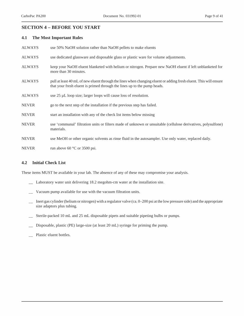
4.1 The Most Important Rules
ALWAYS use 50% NaOH solution rather than NaOH pellets to make eluents
ALWAYS use dedicated glassware and disposable glass or plastic ware for volume adjustments.
ALWAYS keep your NaOH eluent blanketed with helium or nitrogen. Prepare new NaOH eluent if left unblanketed formore than 30 minutes.
ALWAYS pull at least 40 mL of new eluent through the lines when changing eluent or adding fresh eluent. This will ensurethat your fresh eluent is primed through the lines up to the pump heads.
ALWAYS use 25 µL loop size; larger loops will cause loss of resolution.
NEVER go to the next step of the installation if the previous step has failed.
NEVER start an installation with any of the check list items below missing
NEVER use ‘communal’ filtration units or filters made of unknown or unsuitable (cellulose derivatives, polysulfone)materials.
NEVER use MeOH or other organic solvents as rinse fluid in the autosampler. Use only water, replaced daily.
NEVER run above 60 °C or 3500 psi.
4.2 Initial Check List
These items MUST be available in your lab. The absence of any of these may compromise your analysis.
__ Laboratory water unit delivering 18.2 megohm-cm water at the installation site.
__ Vacuum pump available for use with the vacuum filtration units.
__ Inert gas cylinder (helium or nitrogen) with a regulator valve (ca. 0–200 psi at the low pressure side) and the appropriatesize adaptors plus tubing.
__ Sterile-packed 10 mL and 25 mL disposable pipets and suitable pipeting bulbs or pumps.
__ Disposable, plastic (PE) large-size (at least 20 mL) syringe for priming the pump.
__ Plastic eluent bottles.

CarboPac PA200 Document No. 031992-01 Page 10 of 41
SECTION 5 – PREPARATION OF ELUENTS AND STANDARDS
NOTEAlways sanitize the entire analyzer with 2M NaOH prior to initial start-up (see Section 6) and after idle periods.
Obtaining reliable, consistent and accurate results requires eluents that are free from ionic and electrochemically active impurities.Chemicals and deionized water used to prepare eluents must be of the highest purity available. Maintaining low trace impuritiesand low particle levels in eluents also help to protect your ion exchange columns and system components. Dionex cannot guaranteeproper column performance when the quality of the chemicals, solvents and water used to prepare eluents is substandard.
5.1 Eluent E1: Deionized Water
Vacuum degas the water by placing the eluent reservoir in a sonicator and drawing a vacuum on the filled reservoir with a vacuumpump. Vacuum degas the reservoir for 5–10 minutes while sonicating. Cap each bottle and minimize the length of time the bottleis opened to the atmosphere. Online degassing is supported through the use of the GP40, GP50 and GS50 gradient pumping systemsand the IS20 and IS25 isocratic pumping systems.
5.2 Eluent E2: 200 mMSodium Hydroxide
The first step in the preparation of sodium hydroxide eluent is to degas an aliquot (typically 900 mL) of the deionized water, asdescribed above. To make 0.2 M NaOH, add 16 g (10.4 mL) of 50% (w/w) NaOH to the degassed deionized water by removingthe NaOH aliquot from the middle of the stock solution where sodium carbonate is least likely to have formed. Do not pipet fromthe bottom where sodium carbonate precipitate may have fallen, and always discard the bottle of 50% sodium hydroxide when itreaches about 2/3 empty. Place the tip of the pipet containing the aliquot of NaOH about 1 inch below the surface of the water anddispense the NaOH. If done properly, without stirring, most of the concentrated sodium hydroxide will stay at the lower half ofthe container and the rate of carbon dioxide adsorption will be much lower than that of a homogenous solution. Seal the containerafter the sodium hydroxide transfer is complete. Remember to replace the cap to the 50% hydroxide bottle immediately as well.Mix the contents of the tightly sealed container holding the 1M hydroxide.
NOTEDO NOT prepare NaOH eluents from sodium hydroxide pellets! The pellets are coated with a layer of carbonate.
Always degas and store NaOH eluents in plastic eluent bottles blanketed with helium or nitrogen to avoid carbondioxide contamination from the air. Carbonate in the eluent can significantly reduce retention times forcarbohydrates.
The eluents can be prepared by either weight or by volume. Using a volumetric pipet is more effective in preventing contaminationthan the weight method, but is less precise. For applications requiring less than or equal to 100 mM hydroxide, an on-line eluentgenerator may be used. Thus the preparation of caustic eluents may be avoided altogether. Table 1, below, lists the mass or volume,of NaOH (50% w/w) required in 1 L to make the listed concentrations. Decide which technique to use, mass or volume, and thenalways use the same methodology to ensure consistent chromatographic results.
The sodium hydroxide eluents used with the CarboPac PA200 column will readily absorb carbon dioxide, producing sodiumcarbonate. The presence of variable amounts of carbonate will lead to inconsistent retention times, therefore always degas the waterprior to use, discard the 50% sodium hydroxide once it is 2/3 empty and keep the prepared eluent blanketed under an inert gas.

CarboPac PA200 Document No. 031992-01 Page 11 of 41
Table 1Mass or Volume of NaOH Required to Make 1 L of Common Eluents
5.3 Eluent E3: 100 mM Sodium Hydroxide
To make 0.1 M NaOH, add 8.0 g (5.2 mL) of 50% (w/w) NaOH to the degassed deionized water by removing the NaOH aliquotfrom the middle of the stock solution where sodium carbonate is least likely to have formed. Do not pipet from the bottom wheresodium carbonate precipitate may have fallen, and always discard the bottle of 50% sodium hydroxide when it reaches about 2/3 empty. Place the tip of the pipet containing the aliquot of NaOH about 1 inch (2.54 cm) below the surface of the water and dispensethe NaOH. If done properly, without stirring, most of the concentrated sodium hydroxide will stay at the lower half of the containerand the rate of carbon dioxide adsorption will be much lower than that of a homogenous solution. Seal the container after the sodiumhydroxide transfer is complete. Remember to replace the cap to the 50% hydroxide bottle immediately as well. Mix the contentsof the tightly sealed container holding the 0.1 M hydroxide.
5.4 Eluent E4: 100 mM Sodium Hydroxide/ 1 M Sodium Acetate
To maintain baseline stability, it is important to keep the sodium hydroxide concentration constant during the sodium acetategradient, because acetate has no buffering capacity at high pH. This is achieved by making the eluents as follows:
Eluent A: x mM NaOHEluent B: x mM NaOH, y mM NaOAc
To make one (1) liter of 0.1 M sodium hydroxide/ 1.0 M sodium acetate, dispense approximately 800 mL of DI water into a 1 Lvolumetric flask. Vacuum degas for approximately 5 minutes. Add a stir bar and begin stirring. Weigh out 82.0 g anhydrous,crystalline sodium acetate. Add the solid acetate steadily to the briskly stirring water to avoid the formation of clumps which areslow to dissolve. Once the salt has dissolved, remove the stir bar with a magnetic retriever. Add DI water to the flask to bring thevolume to the 1 L mark.
Vacuum filter the solution through a 0.2 µm nylon filter. This may take a while as the filter may clog with insoluble material fromthe sodium acetate. Using a plastic tip volumetric pipet, measure 5.2 mL of 50% (w/w) sodium hydroxide solution from the middleof the bottle. Dispense the sodium hydroxide solution into the acetate solution about 1 inch under the surface of the acetate solution.The eluent should be kept blanketed under helium at 34 to 55 kPa (5–8 psi) at all times, and last about 1 week.
NOTEDionex recommends the use of dedicated glassware, pipets and filtration apparatus for exclusive use in thepreparation of carbohydrate eluents.
Eluent concentration NaOH (g) NaOH (mL) 0.1 M 8.0 5.2 0.2 M 16.0 10.5 0.3 M 24.0 15.7 0.4 M 32.0 20.9 0.5 M 40.0 26.1 0.6 M 48.0 31.4 0.7 M 56.0 36.6 0.8 M 64.0 41.8 0.9 M 72.0 47.1 1.0 M 80.0 52.3

CarboPac PA200 Document No. 031992-01 Page 12 of 41
5.5 Carbohydrate Sialylated N-linked Alditol Standard
The Dionex OligoStandard, Sialylalted N-Linked Alditols, P/N 043164 contains 25 nmol oligosaccharides purified from bovinefetuin. Dilute the standard prior to use, by adding a known volume of DI water (for example 1 mL). An injection of 25 µL willcorrespond to an injection of 625 pmol of the standard. Dionex recommends running this standard every time a new column isinstalled and subsequently anytime it becomes necessary to troubleshoot your system.

CarboPac PA200 Document No. 031992-01 Page 13 of 41
SECTION 6 – GETTING STARTED
6.1 Introduction To The Detection Methods
The carbohydrate oxidation at gold electrodes is made possible by a rapid sequence of potentials (waveform) adjusted betweenthe working electrode (gold) and the reference electrode (Ag/AgCl). Resulting currents are measured by integration during a shorttime interval of the detection waveform. The standard, recommended carbohydrate waveform is shown in Table 2.
Table 2Carbohydrate Quadruple Waveform
NOTEDo not polish a new gold electrode prior to use. NEVER POLISH the disposable gold electrodes.
Refer to section 9 – Troubleshooting Guide of this manual for an overview of reconditioning techniques for gold workingelectrodes.
The reference electrode for the ED50 is a combination pH-Ag/AgCl electrode (P/N 044198). For carbohydrate analysis, thiselectrode is used in the Ag mode; for amino acid analyses it is used in the pH mode. Always verify the correct selection of referenceelectrode is made in the program file and on the ED50 module prior to turning the cell voltage on. The reference electrode selectionis made in the Detail Menu Screen on the ED50 front panel. The ‘Ref’ display should read ‘Ag’.
It is advantageous to always have available at least one unused “known good” reference electrode. If stored in saturated KCl, areference electrode can be kept for years with its reference potential virtually unchanged. In contrast, the reference electrodesmounted inside the electrochemical cell and exposed to flowing sodium hydroxide have only a limited lifetime of ca. 3 to 6 months.As a result of prolonged exposure to alkaline solutions, the 0.1 M KCl solution inside the reference electrode gradually becomesalkaline and the silver chloride layer on the Ag wire immersed into that solution either dissolves or converts to a mixture of silveroxide and silver hydroxide. As that happens, the reference potential shifts and becomes increasingly unstable. Shifting referencepotential is experienced by the user either as an unusually high background or as a decrease in signal response. A combination ofboth effects is also possible.
CAUTIONNever leave a reference electrode inside a disconnected electrochemical cell.
Time (sec) Potential (V) vs. Ag/AgCl
Integration
0.00 +0.1 0.20 +0.1 Begin 0.40 +0.1 End 0.41 –2.0 0.42 –2.0 0.43 +0.6 0.44 –0.1 0.50 –0.1
CarboPac PA200 Document No. 031992-01 Page 14 of 41
A reference electrode can be irreversibly damaged by drying out. This happens most frequently by leaving the reference electrodeinside a disconnected electrochemical cell. Always remove the reference cell from the electrochemical cell, when the system isnot in proper use (i.e. cell inlet and outlet are not plugged or connected to a flowing eluent). After removal from the electrochemicalcell, keep the reference electrode immersed in 3 M KCl solution (224 g KCl/L) at all times.
6.2 Sample Preparation
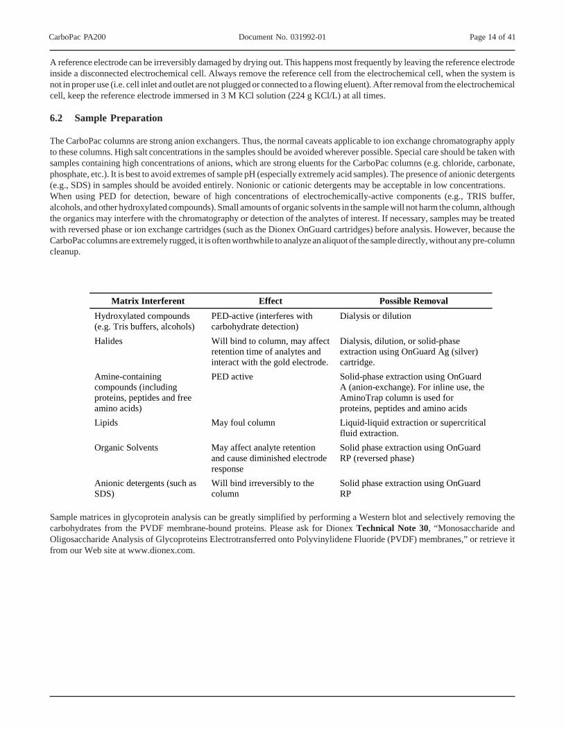
The CarboPac columns are strong anion exchangers. Thus, the normal caveats applicable to ion exchange chromatography applyto these columns. High salt concentrations in the samples should be avoided wherever possible. Special care should be taken withsamples containing high concentrations of anions, which are strong eluents for the CarboPac columns (e.g. chloride, carbonate,phosphate, etc.). It is best to avoid extremes of sample pH (especially extremely acid samples). The presence of anionic detergents(e.g., SDS) in samples should be avoided entirely. Nonionic or cationic detergents may be acceptable in low concentrations.When using PED for detection, beware of high concentrations of electrochemically-active components (e.g., TRIS buffer,alcohols, and other hydroxylated compounds). Small amounts of organic solvents in the sample will not harm the column, althoughthe organics may interfere with the chromatography or detection of the analytes of interest. If necessary, samples may be treatedwith reversed phase or ion exchange cartridges (such as the Dionex OnGuard cartridges) before analysis. However, because theCarboPac columns are extremely rugged, it is often worthwhile to analyze an aliquot of the sample directly, without any pre-columncleanup.
Sample matrices in glycoprotein analysis can be greatly simplified by performing a Western blot and selectively removing thecarbohydrates from the PVDF membrane-bound proteins. Please ask for Dionex Technical Note 30, “Monosaccharide andOligosaccharide Analysis of Glycoproteins Electrotransferred onto Polyvinylidene Fluoride (PVDF) membranes,” or retrieve itfrom our Web site at www.dionex.com.
Matrix Interferent Effect Possible Removal Hydroxylated compounds (e.g. Tris buffers, alcohols)
PED-active (interferes with carbohydrate detection)
Dialysis or dilution
Halides Will bind to column, may affect retention time of analytes and interact with the gold electrode.
Dialysis, dilution, or solid-phase extraction using OnGuard Ag (silver) cartridge.
Amine-containing compounds (including proteins, peptides and free amino acids)
PED active Solid-phase extraction using OnGuard A (anion-exchange). For inline use, the AminoTrap column is used for proteins, peptides and amino acids
Lipids May foul column Liquid-liquid extraction or supercritical fluid extraction.
Organic Solvents May affect analyte retention and cause diminished electrode response
Solid phase extraction using OnGuard RP (reversed phase)
Anionic detergents (such as SDS)
Will bind irreversibly to the column
Solid phase extraction using OnGuard RP

CarboPac PA200 Document No. 031992-01 Page 15 of 41
SECTION 7 – INSTALLATION AND STARTUP
There are three distinct stages during an installation of a new carbohydrate system.
A. System configuration and start-upB. Verification of system cleanlinessC. Verification of system functionality.
Make sure that each section passes before moving onto the next. If you are having problems, check the troubleshooting guide atthe end of this procedure. If you are still having problems, call Dionex.
7.1 System Configuration and Startup
Configure the system with the AS50 autosampler on the left, the injection module in the middle and the pump on the right. Thedetector should be placed on top of the pump. Nitrogen or helium should be delivered to the eluent organizer with about 5–6 psiat each bottle. Make sure that the AS50 TC is plumbed with red (0.005" i.d., P/N 52310) tubing, NOT BLACK, and that extra careis taken to minimize dead volume (see section 6.2 below). Make all fluidic and electrical connections, but do not install the columnyet. Instead install some backpressure tubing, such as a length of yellow (0.001" i.d.) tubing between the injector and detector cellinlet. Minimize the number of unions and the length of all the liquid lines. Tubing between the injection valve and the detector,on either side of the column, should be 0.005" i.d. PEEK tubing. The use of larger tubing will decrease peak resolution. Verifythat the modules are communicating.
7.1.1 AS50 Thermal Compartment Modification for 2-mm Operation
NOTEIf you are using an AS50 with Thermal Compartment, read this section.
The Thermal Compartment (TC) sold with the AS50 and intended for use with carbohydrate systems is shipped pre-plumbed withblack (0.010" i.d.) tubing in the L-box. This tubing in the L-box of the AS50TC is approximately 2 feet of standard bore tubingafter the injection valve, but before the guard column. This tubing must be removed and replaced with the appropriate length ofred (0.005" i.d.) tubing for the carbohydrate resolution to be optimal.
To confirm the tubing inside the L-box is really black, remove the top cover of the L-box (3 knurled screws) and find the “chase”or hole right near the bend, at the bottom of the assembly, where the tubing connects to the guard column(s). You will see 2 piecesof tubing near this “window,” if they are black, proceed as follows:
A. Remove the 3 Allen screws that secure the L-box to the Thermal Compartment, using a #3 metric Allen wrench.
B. Dismount the L-box from the Thermal Compartment and you will find the PEEK tubing running through a “groovechannel”. The L-box has 2 groove channels, the longer one is for use with black PEEK tubing, and the shorter one isfor the red PEEK tubing.
C. Remove the black tubing and attach 10–12 inches of red (0.005" i.d.). This length should be as short as possible butshould be of sufficient length to bend into the thermal compartment and connect to the Rheodyne valve on one end andthe guard column on the other end.
D. The groove channels have an outer diameter (o.d.) of 0.61". PEEK tubing has an o.d. of 0.62". This is so the PEEKtubing makes good contact with the metal body of the L-box in order to maximize thermal accuracy. The PEEK tubingmust be fitted carefully into the groove channel so that it is seated completely. To complete this, you may need to usea flat-bladed screwdriver or similar tool to push the tubing down into the channel, be careful not to bend or otherwisedistress the tubing any more than is necessary.
E. When completed, you should not see any tubing sticking up above or out of the groove. Remount the L-box and replacethe cover, making sure that the cover is tightly secured, with no obvious gaps, again to ensure temperature stability.
F. Attach the end of the red tubing exiting the L-box to the inlet of the injection valve.

CarboPac PA200 Document No. 031992-01 Page 16 of 41
7.1.2 Installation of Disposable Electrodes
The Teflon gaskets included in each package of disposable electrodes must be used; otherwise, the disposable electrode productwarranty is void. In addition, the quadruple waveform must be used for carbohydrate analysis otherwise the product warranty isvoid. Always wear gloves when handling electrodes. Never touch the electrode surface.
STEP 1Check availability of all parts
STEP 2Install the special gasket.
STEP 3Install disposable electrode
STEP 4Place the working electrode blockover the Disposable Electrodeand tighten the wing nuts
The ED40, ED50 or ED50A cell bodywith reference electrode installed
Special Gasket for Disposable Electrode
Disposable Electrode
Dionex working electrode blockP/N 044112 or 060297
Wing Nuts
Check that the gasket orientation is correct.Avoid any wrinkles inside the sealing area of the gasket.
Make sure the Disposable Electrode is oriented correctly.The gold electrode must face the ED40, ED50 or ED50A cell body.
Tighten the wing nuts evenly and “finger tight” only.Do not use tools such as pliers.

CarboPac PA200 Document No. 031992-01 Page 17 of 41
7.1.3 System Rinse
NOTERINSE a new system with 2 M NaOH prior to use.
DO NOT install the CarboPac PA200 column before confirming that the background < 30 nC.
Prepare a solution of 2 M NaOH to rinse each bottle, by diluting 104 mL of 50% sodium hydroxide to 1 L with deionized waterusing the techniques described in section 4.2. Place the 2 N NaOH in a pre-rinsed bottle and place all 4 eluent lines in it. Withdrawat least 40 mL of sodium hydroxide from each line, using a syringe. Close the solvent draw-off valve and leave the pumpproportioning 25/25/25/25 for 15 minutes. Make sure that all surface come into contact with the sodium hydroxide; rotate theinjector valve. Repeat the process with 18.2 megohm-cm water.
7.2 Verification Of System Cleanliness
Prepare a new set of eluents as described in section 5.1, 5.2 and 5.3 and fill the eluent bottles. Set the eluent composition to 100%for each eluent line and draw out at least 40 mL of eluent from each eluent line.
7.2.1. System Background Check
This section is performed using the conditions of the test chromatogram. Make sure that
A. the cell is not yet on,B. the pump is pumping 100 mM NaOH, 50 mM NaOAC at 0.5 mL/min,C. a length of yellow tubing is installed between the injector and detector cell to generate ~1000 psi backpressure,D. the columns are not yet installed.
Confirm that the pH reading on the detail screen of the detector is between 12.8 and 13.4. With the pH within this range, turn onthe cell using the quadruple waveform in Table 1 (Section 6.1) and begin monitoring the background signal from the control panelfor at least 30 minutes. Confirm that the baseline is < 30 nC. If the background > 30 nC or the pH is out of range, see the“Troubleshooting” section at the end of this manual.
7.2.2 Verification of Column Cleanliness
Install the CarboPac PA200 column set only after the initial system test (7.1.3. and 7.2.1) determines a background level withinthe specified range. A premature installation on a contaminated system will cause delays during the column equilibration.
The CarboPac PA200 is shipped in 100 mM NaOH/50 mM NaOAc. Any column that is stored long-term should be stored in thesame solution. To prepare the column for standard analysis, the CarboPac PA200 must be washed for at least 20 minutes at 0.5mL/min using 250 mM NaOAc in 100 mM NaOH. Following the wash, equilibrate the column using your starting conditions for15–20 minutes. Next, switch your injection valve to LOAD (the loop now contains eluent equivalent to the initial conditions) andthen connect the column to the cell.
Equilibrate the column set by performing two blank injections (DI water) under the test chromatogram conditions, including thecolumn regeneration and re-equilibration steps. Should the background shift exceed 10 nC, perform the 2M NaOH wash asdescribed in section 7.1.3.
Once the columns are equilibrated, inject a system suitability standard such as the Dionex OligoStandard, to establish theperformance of the column at start-up. This chromatogram can then be referred to when troubleshooting your system. Once youobtain your expected chromatography, you are ready to proceed to running your application.
Dionex recommends that the system suitability standard be run whenever you reinstall a column after long-term storage.

CarboPac PA200 Document No. 031992-01 Page 18 of 41
SECTION 8 – APPLICATIONS
The CarboPac PA200 columns have been designed for isocratic or gradient separation using sodium hydroxide eluents up to aconcentration of 1 M with sodium acetate gradients. Analyte separation is highly dependent on hydroxide concentration in HPAEC.Many separations require only an isocratic separation. However, some groups of analytes will require a step or gradient elution.Retention of carbohydrates can be varied with eluent concentration, in some cases changing the elution order as the eluentconcentration increases.
Depending upon your system, you may have to make small adjustments to your gradient conditions or operating temperature toachieve resolution of all analytes.
8.1 Glycoprotein Characterization and Quality Control
Most secreted and cell surface proteins are glycosylated. They typically have multiple glycosylation sites, each site containingseveral structures. Therefore a protein can exist in many glycoforms. Glycans present on the protein can have a profound effecton the protein structure, and on biological function. Therefore the study of glycans is an important part of protein characterization.Biopharmaceuticals, including glycoproteins require thorough characterization and analysis to meet European, US and Japaneseregulatory standards for New Drug Approval as defined by the International Conference for Harmonization (ICH) process. Evenat clinical trial stage the national requirements for conduct of clinical studies necessitate clear identification, quality and purity ofthe investigational drug (FDA guidance documents for IND, MCA guidelines for CTX).

CarboPac PA200 Document No. 031992-01 Page 19 of 41
Figure 2Fetuin Oligosaccharide Profiles: CarboPac PA200 vs. CarboPac PA100
8.1.1 Fetuin Oligosaccharide Alditol Profiling
The high resolution of the CarboPac PA200 is exemplified in the following example. CarboPac columns separate mono-, oligo-and polysaccharides on the basis of fine structural differences in branching, linkage isomerism, anomericity and sialylation. In thefetuin oligosaccharide alditol standard shown below, peaks are separated according to branching, sialylation and linkageisomerism. The disialylated biantennary peaks are eluted before the trisialylated triantennary peaks which are eluted before thetetrasialylated tetraantennary peaks. In addition, within each grouping, the α2-6 isomer is eluted before, and well resolved from,the α2-3 isomer.
The Dionex OligoStandard, Sialylalted N-Linked Alditols, P/N 043164 contains 25 nmol oligosaccharides purified from bovinefetuin. Dilute the standard prior to use, by adding a known volume of DI water (for example 1 mL; a 25 µL injection correspondsto 625 pmol of oligosaccharide). Dionex recommends running this standard every time a new column is installed and subsequentlyanytime it becomes necessary to troubleshoot your system.
Columns: CarboPac PA200 (3 x 250 mm) and CarboPac PA100 (4 x 250 mm)Gradient: PA200:
20–150mM NaOAc in 100 mM NaOH over 1 hPA100:20–200 mM NaOAc in 100 mM NaOH over 1 h
Flow Rate:PA200: 0.5 mL/minPA100: 1mL/min
Detection: Pulsed amperometry, QP waveform, gold electrodeSamples: Fetuin oligosaccharide alditol stnd
0.0 5.0 10.0 15.0 20.0 25.0 30.0 35.0 40.0 45.0 50.0 55.0 60.0 65.0 70.0
nC
min
2
1
PA200
PA100

CarboPac PA200 Document No. 031992-01 Page 20 of 41
8.1.2 Antibodies Separations
Today, monoclonal antibodies comprise the cornerstone of numerous medical and scientific procedures and thus are producedroutinely for both medical and research applications. In the medical world, they are used as diagnostics, to detect cancers orinfection by certain bacteria or viruses; as vaccines, to boost the body's immune response; and as therapeutics, to target foreignbacteria, viruses or cancerous cells.
Monoclonal Antibody Profile
Columns: CarboPac PA200 (3 x 250 mm) and CarboPac PA100 (4 x 250 mm)Gradient: 10 mM or 20 mM – 150 mM NaOAc in 100 mM NaOH over 60 minFlow Rate:PA200: 0.5 mL/minPA100: 1mL/minDetection: Pulsed amperometry, QP waveform, gold electrodeSample: 48 h PNGase F digest of monoclonal antibody (100 µg)
Minutes
0 5 10 15 20 25 30 35 40 45
nC
20
50
100
150
200
250
PA200
PA100
Minutes
0 5 10 15 20 25 30 35 40 45
nC
20
50
100
150
200
250
PA200
PA100
Figure 3CarboPac PA200 vs. CarboPac PA100 Separation of Monoclonal Antibody N-linked Oligosaccharides
CarboPac PA200 Document No. 031992-01 Page 21 of 41
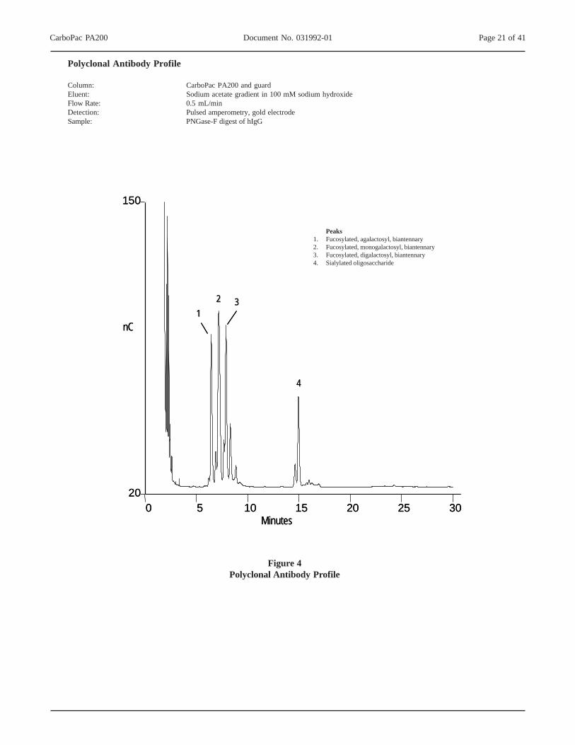
Polyclonal Antibody Profile
Column: CarboPac PA200 and guardEluent: Sodium acetate gradient in 100 mM sodium hydroxideFlow Rate: 0.5 mL/minDetection: Pulsed amperometry, gold electrodeSample: PNGase-F digest of hIgG
nC
Minutes0 5 10 15 20 25 30
20
150
1122 33
44
nC
Minutes0 5 10 15 20 25 30
20
150
1122 33
44
Peaks1. Fucosylated, agalactosyl, biantennary2. Fucosylated, monogalactosyl, biantennary3. Fucosylated, digalactosyl, biantennary4. Sialylated oligosaccharide
Figure 4Polyclonal Antibody Profile
CarboPac PA200 Document No. 031992-01 Page 22 of 41
8.2 Profiling of Complex Plant Carbohydrates
8.2.1 Profiling of Inulins
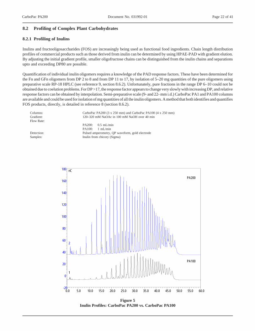
Inulins and fructooligosaccharides (FOS) are increasingly being used as functional food ingredients. Chain length distributionprofiles of commercial products such as those derived from inulin can be determined by using HPAE-PAD with gradient elution.By adjusting the initial gradient profile, smaller oligofructose chains can be distinguished from the inulin chains and separationsupto and exceeding DP80 are possible.
Quantification of individual inulin oligomers requires a knowledge of the PAD response factors. These have been determined forthe Fn and GFn oligomers from DP 2 to 8 and from DP 11 to 17, by isolation of 5–20 mg quantities of the pure oligomers usingpreparative scale RP-18 HPLC (see reference 9, section 8.6.2). Unfortunately, pure fractions in the range DP 6–10 could not beobtained due to coelution problems. For DP >17, the response factor appears to change very slowly with increasing DP, and relativeresponse factors can be obtained by interpolation. Semi-preparative scale (9- and 22- mm i.d.) CarboPac PA1 and PA100 columnsare available and could be used for isolation of mg quantities of all the inulin oligomers. A method that both identifies and quantifiesFOS products, directly, is detailed in reference 8 (section 8.6.2).
Columns: CarboPac PA200 (3 x 250 mm) and CarboPac PA100 (4 x 250 mm)Gradient: 120–320 mM NaOAc in 100 mM NaOH over 40 minFlow Rate:
PA200: 0.5 mL/minPA100: 1 mL/min
Detection: Pulsed amperometry, QP waveform, gold electrodeSamples: Inulin from chicory (Sigma)
Figure 5Inulin Profiles: CarboPac PA200 vs. CarboPac PA100
0.0 5.0 10.0 15.0 20.0 25.0 30.0 35.0 40.0 45.0 50.0 55.0 60.0-20
0
20
40
60
80
100
120
140
160
180 nC
2
1
PA200
PA100

CarboPac PA200 Document No. 031992-01 Page 23 of 41
8.2.2 Amylopectins
HPAE-PAD with gradient elution has been used for structural studies on starch-derived materials such as amylopectins since thechain length distribution is an important parameter for characterizing the molecular structure. These distributions can be used asfingerprints for the amylopectin source.
Column: CarboPac PA200 and guardEluent: Sodium acetate gradient in 100 mM Sodium hydroxide 70 to 300 mM in 30 minFlow Rate: 0.5 mL/minTemperature: 30 °CInjection Vol: 5 µL from 10 µL loopDetection: Pulsed amperometry, gold electrodeSample: Red Hook Amber Ale 1:50 dilution
nC
0 5 10 15 2030
330
Minutes
nC
0 5 10 15 2030
330
Minutes
Figure 6Amylopectins Separated on the CarboPac™ PA200 Column

CarboPac PA200 Document No. 031992-01 Page 24 of 41
8.3 Sialyl Lactose (N-Acetylneuraminyl-Lactose)
The following chromatography is used as the quality assurance test for the CarboPac PA200 column. Every CarboPac PA200column is tested with respect to sialyl lactose peak efficiency. Chromatography of sialyl lactose on the CarboPac PA200 columnexhibits greater than a twofold increase in peak efficiencies compared to chromatography of sialyl lactose on the CarboPac PA100column.
Columns: CarboPac PA200 (3 x 250 mm) or CarboPac PA100 (4 x 250 mm)Gradient:
PA200: 100 mM NaOH, 50 mM NaOAc isocraticPA100: 100 mM NaOH, 100 mM NaOAc isocratic
Flow Rate:PA200: 0.5 mL/minPA100: 1 mL/min
Detection: Pulsed amperometry, QP waveform, gold electrodeSample: NanLac Std
0.0 1.0 2.0 3.0 4.0 5.0 6.0 7.0 8.0 9.0 10.00.0
10.0
20.0
30.0
40.0
55.0nC
min
1
NanLac
NanLac
PA200NanLac peak ≈ 12,000 plates
PA100NanLac peak ≈ 4,000 plates
Figure 7Chromatography of NanLac on the CarboPac PA200 exhibits > 2x the peak efficiencies compared to the
CarboPac PA100

CarboPac PA200 Document No. 031992-01 Page 25 of 41
8.4 Separation of Mannose 7 D1, D3 Isomers
High mannose isomers that frequently would not be distinguishable by other techniques are well separated on both the CarboPacPA200 and PA100 columns. The separation of these isomers is better on the CarboPac PA200 column.
Columns: CarboPac PA200 (3 x 250 mm) or CarboPac PA100 (4 x 250 mm)Gradient: 0–200 mM NaOAc in 100 mM NaOH over 110 minutesFlow Rate:
PA200: 0.5 mL/minPA100: 1 mL/min
Detection: Pulsed amperometry, QP waveform, gold electrodeSample: Mannose 7 isomers (Dextra Labs):
0.0 2.0 4.0 6.0 8.0 10.0 12.0 14.0 16.0 18.0 20.0 22.0 25.0-10.0
0.0
10
20
30
40
50
60
70 nC
min
D1 isomer
D3 isomer
D1 isomerD3 isomer
PA200
PA100
Figure 8CarboPac PA200 vs. CarboPac PA100 Separation of Mannose 7 D1,7D3 Isomers

CarboPac PA200 Document No. 031992-01 Page 26 of 41
8.5 Separation of Neutral N-Linked Oligosaccharides
N-linked glycoproteins may exhibit micro-heterogeneity with respect to the N-linked oligosaccharides that may be present. NeutralN-linked oligosaccharides released from glycoproteins could be of the complex or high mannose variety. A comparison ofchromatography of neutral and high mannose oligosaccharides on the CarboPac PA200 column compared to the CarboPac PA100column shows that the separation window is wider for the CarboPac PA200 column. Early eluting oligosaccharides on theCarboPac PA100 column tend to elute earlier on the CarboPac PA200 column.
8.5.1 Complex Neutral Structures
Columns: CarboPac PA200 (3 x 250 mm) or CarboPac PA100 (4 x 250 mm)Gradient: 0–200 mM NaOAc in 100 mM NaOH over 110 minutesFlow Rate:
PA200: 0.5 mL/minPA100: 1 mL/min
Detection: Pulsed amperometry, QP waveform, gold electrode
Samples:1. Asialo agalacto biantennary standard2. Asialo galacto biantennary standard3. Asialo galacto fuco biantennary standard4. Asialo triantennary standard5. Asialo tetraantennary standard
(All standards are from Dextra Labs)
0.0 2.0 4.0 6.0 8.0 10.0 12.0 14.0 16.0 18.0 20.0 22.0 25.0
0.0
nC
min
54
321
PA200
0.0 2.0 4.0 6.0 8.0 10.0 12.0 14.0 16.0 18.0 20.0 22.0 25.0
nC
min
54
321
PA100
0.0 2.0 4.0 6.0 8.0 10.0 12.0 14.0 16.0 18.0 20.0 22.0 25.0
0.0
nC
min
54
321
PA200
0.0 2.0 4.0 6.0 8.0 10.0 12.0 14.0 16.0 18.0 20.0 22.0 25.0
nC
min
54
321
PA100
Figure 9CarboPac PA200 vs. CarboPac PA100
Separation of Neutral N-linked Oligosaccharides (complex neutral structures)

CarboPac PA200 Document No. 031992-01 Page 27 of 41
0.0 2.0 4.0 6.0 8.0 10.0 12.0 14.0 16.0 18.0 20.0 22.0 25.0-60
0
50
100 nC
min
54321
PA200
0.0 2.0 4.0 6.0 8.0 10.0 12.0 14.0 16.0 18.0 20.0 22.0 25.0-80
0
80 nC
min
54
321
PA100
8.5.2 High Mannose Structures
Columns: CarboPac PA200 (3 x 250 mm) or CarboPac PA100 (4 x 250 mm)Gradient: 0–200 mM NaOAc in 100 mM NaOH over 110 minutesFlow Rate:
PA200: 0.5 mL/minPA100: 1mL/min
Detection: Pulsed amperometry, QP waveform, gold electrode
Samples:1. mann 3 standard2. mann 5 standard3. mann 6 standard4. mann 7 standard5. mann 8 standard
(All standards are from Dextra Labs)
Figure 10CarboPac PA200 vs. CarboPac PA100
Separation of Neutral N-linked Oligosaccharides (high mannose structures

CarboPac PA200 Document No. 031992-01 Page 28 of 41
8.6 HPAE-PAD Oligosaccharide Resources
This list is not intended to be comprehensive. In addition, none of these resources specifically uses the CarboPac PA200, whichis a newly introduced column. However, these resources can be used to determine starting conditions for separations on theCarboPac PA200, with higher efficiencies and lower sodium acetate requirements.
8.6.1 Basic HPAE-PAD Resources - Dionex Applications
TN20 Analysis of Carbohydrates by High Performance Anion Exchange Chromatography with Pulsed AmperometricDetection (HPAE-PAD)
TN21 Optimal Settings for Pulsed Amperometric Detection of Carbohydrates Using the Dionex ED40 ElectrochemicalDetector
TN30 Monosaccharide and Oligosaccharide Analysis of Glycoproteins Electrotransferred onto PolyvinylideneFluoride (PVDF) Membranes
TN36 Analysis of Exoglycosidase Digestions of N-Linked Oligosaccharides Using HPAE-PAD
TN42 Glycoprotein Oligosaccharide Analysis Using High-Performance Anion-Exchange Chromatography
AN46 Ion Chromatography: A Versatile Technique for the Analysis of Beer
AN67 Polysaccharide Analysis: Maltodextrins, Dextrans, Inulin and Other Oligosaccharides
AN82 Analysis of Fruit Juice Adulterated with Medium Invert Sugar from Beets
AN105 Glycosylation Analysis of Human Serum Transferrin Glycoforms Using Pellicular Anion-ExchangeChromatography
8.6.2 HPAE-PAD Oligosaccharide Resources
1. Thayer, J., et al. (1998) Anal. Biochem., 256, 207-216 (Online desalting Paper).
2. Field, M., et al (1996) Anal. Biochem., 239 92-98 (HPAE-PAD and MS to monitor oligosaccharide degradation).
3. Rohrer, J., (1995), Glycobiology., 5, 359-360, (Empirical relationship between structure and detection).
4. Rohrer, J. S. et al., (1995) Glycobiology 5, 391-395 (Sepn of Partially Desialylated Branched OligosaccharideIsomers).
5. Cooper, G. A. et.al. (1995) Anal. Biochem. 226, 182-184 (Separation of Neutral Asparagine-Linked Oligosaccharides).
6. Weitzhandler, M., et al. (1994) J. Pharm. Sci., 83(12), 1670-1675 (Analysis of Carbohydrates on IgG Preparations).
7. Hardy, M. R. et al. (1988) Proc. Natl. Acad. Sci. (USA), 85, 3289-3293 (Separation of Positional Isomers ofOligosaccharides and Glycopeptides).
8. Durgnat, J-M, Martinez, C. Determination of fructooligosaccharides in raw materials and finished products by HPAE-PAD. Semin Food Anal (1997), 2, 85–97.
9. Timmermans, J.W., van Leeuwen, M.M., Tournois, H., deWit ,D. and Vliegenthart J., Quantitative analysis of themolecular weight distribution of inulin by means of anion exchange HPLC with pulsed amperometric detection. J.Carbohydr. Chem., (1994), 13(6), 881-888.

CarboPac PA200 Document No. 031992-01 Page 29 of 41
SECTION 9 – TROUBLESHOOTING GUIDE
Remember that some of the problems may be related to parts of your experimental protocol (sample contamination, imprecisionduring sample transfer, problems during peptide or protein hydrolysis, etc.). Make sure to follow the rules from Section 4.1 andto re-check all of the items from Section 4.2. The following text should help you to locate and eliminate problems traceable to thecarbohydrate hardware and chemistries. It also provides a selection of cleanup and reconditioning procedures that have been foundeffective by many users.
9.1 High Background
While it may be possible to obtain reasonable performance even with elevated levels of detection background according to somerequirements, high background frequently brings about an increased size of gradient artifacts and can be accompanied by a presenceof ghost peaks. Detection sensitivity may also change suddenly when the detection background is too high.
A background >30 nC with 10 mM sodium hydroxide at 0.5 mL/min and 30 °C using the quadruple waveform shown in Table 1indicates one of the following possibilities:
A. Incorrect detection parameters.Verify that “Ag” is specified in detector screen 2. Check all values of waveform in detector screen 4 against those inTable 1. If the pH reading at 95/5 (%E1/%E2, i.e. 10 mM NaOH) is above 13.2 replace the reference electrode.
B. Compromised working electrode surface.Briefly install a new working electrode and check the background as above, If the reading remains > 30 nC, removethe new electrode within 30 minutes and continue testing for column or system contamination. Otherwise continue withyour work with the new electrode installed.
C. Column contamination.Remove the column set from the system first and replace it with a length of yellow PEEK tubing, generating a pressuredrop between 1000 and 2000 psi. If the background reading improves after the column is removed from the system,go to section 9.3.
D. Water contamination.Prepare eluents using a fresh (previously unopened) bottle of Burdick and Jackson HPLC Grade water. If thebackground is reduced, investigate the source of contamination in the original source of water.
E. System contamination.If the background remains high even with fresh water and without the column, carry out the 2 M sodium hydroxide rinsedescribed in section 9.5.
9.2 Decreased Detection Sensitivity
Always confirm the loss of response by performing at least one injection of the system suitability standard mix as described inSection 7.4.2. This is to make sure that a decreased level of response is not being caused by system problems discussed in Section9.4.2.
Any decrease in detection sensitivity means that the working electrode surface has been affected. The operator should install a newworking electrode. Spare gold working electrodes should always be available in order to avoid unnecessary delays.
IMPORTANTNever install a new electrode without an aggressive system cleanup (section 9.6).
The exceptions to this rule are described below.
Exception:
Check the pH reading in the Detail Screen of the ED50. If the value is out of range or >13.2, install a new reference electrode andthen install a new gold working electrode (P/N 55832). The system cleanup is not necessary. The decrease in sensitivity was caused
CarboPac PA200 Document No. 031992-01 Page 30 of 41
by a gold-oxide-buildup on the electrode surface because the reference potential was too high. The non-disposable gold workingelectrode can be reconditioned by the repair polishing described in section 9.7.1.
After installing a new working electrode (with or without the complete system cleanup), confirm the normal detection sensitivity.Carry out the monosaccharide injection test, section 6.4.2. Should the response be too low (peak height < 6 nC for 10 µL injections),immediately remove the new working electrode from the system.
9.3 Column Problems
The guard column protects the main column not only from contamination but also from excessive pressure fluctuations caused bythe instrument or by operator errors. Have the guard column installed at all times, disconnect it only during some of the testingdescribed in this section, or when priming the pump to prevent accidental over pressure.
The column set is causing the high background if the background reading decreases after the column is replaced by a section ofPEEK tubing, as described in section 9.1 c.
9.3.1 Column Set Causing High Background
Disconnect the cell from the system, remove the yellow tubing and reinstall the column set. Increase the column thermostattemperature to 40 °C. Run 2 M sodium hydroxide through the column (at 0.5 mL/min) for one hour. Reset the temperature to 30°C, pump 10 mM sodium hydroxide through the column, connect the cell and apply the quadruple waveform. If the backgroundremains high, remove the cell from the system again and rinse the column with 10 mM NaOH, 950 mM sodium acetate (5% E2,95% E3) for at least four hours, and preferably overnight.
9.3.2 Excessive Gradient Rise
The magnitude of the gradient rise can be minimized by running high eluent strengths during the times when the system is not inuse for sample or standard analysis. This will keep the column conditioned, free from carbonate buildup, and ready for analysis.
A. Make sure the gradient rise is not caused by the system and/or detector cell (see Section 9.4.1).
B. Increase column temperature to 40 °C and wash the guard and column with 100 mM NaOH, 950 mM sodium acetatefor at least four hours (and preferably overnight). Run a blank gradient at 30 °C and if necessary repeat the 100 mMNaOH, 950 mM sodium acetate wash at 40 °C.
9.3.3 Peak Efficiency and Resolution are Decreasing
Always have a spare guard available.
Peak deformations may sometimes be caused by sample matrix.
A. Run a standard separation with the Guard column removed from the system. Install a new Guard column should theseparation improve with the old Guard removed. It is common to replace the Guard column several times during thelifetime of the analytical column.
B. Verify that only the 0.005" i.d. (Red) tubing is installed for all connections between injector and detector.
C.
NOTEIf you are using an AS50 thermal compartment, be sure that it has been modified for 2-mm operation. See Section6.1.1.
D. Verify that the shortest possible length of 0.010" i.d. tubing (black) is installed between the pump and injector.

CarboPac PA200 Document No. 031992-01 Page 31 of 41
E. Check for proper installation of ferrules on all PEEK tubing starting with the injector outlet and all other connectorsto the ED50 cell inlet.
F. Check temperature settings in your method and/or actual temperature in your column oven.
G. The column may be overloaded. Try to inject a smaller amount of your sample or dilute the sample more.
H. If all of the above does not lead to an improved separation, the resin bed of the main column has been damaged andthe main column must be replaced.
9.4 System Problems
9.4.1 High Detection Background Caused by the System
A. Verify the problem is neither the detector (see Section 9.1 a, b) nor column (see Section 9.1 c) related.
B. With injector, column and detector cell installed (cell voltage off) carry out the 2 M NaOH wash as described in Section9.5.
C. Prepare new eluents.
D. Rinse all three eluent lines with the new eluents (at least 40 mL by priming syringe)
9.4.2 No Peaks, Poor Peak Area Reproducibility or too Small Peak Areas
A. Check the position and filling levels of sample vials in the autosampler.
B. Check injector needle-height setting.
C. Check each line of the schedule for proper injector parameters. Revert to full loop and 10 ?L sample loop size if usingother injection modes (push or pull).
D. Service the injection valve (check for leaks, Tefzel fragments, or sediments inside the valve).
9.4.3 Large Baseline Dip in the Chromatogram
A large baseline dip appearing between 17 and 19 minutes when the guard column is installed is usually caused by oxygen in thesample injected. The ‘oxygen dip’ is normal and can be reduced in magnitude with higher NaOH concentration in the eluent.
9.4.4 Incorrect or Variable Retention Times
A. Check your eluent preparation procedure for possible errors.
B. Prime the pump if necessary.
C. Measure the flow rate by weighing out the eluent collected during exactly five minutes of flow. Recalibrate the pumpif necessary.
D. Your sodium hydroxide eluent bottle contains too much carbonate and/or the re-equilibration period at the end of thegradient method is too short.
E. Set the eluent composition for 100% for each eluent and draw out at least 40 mL of eluent from each of the lines.
F. Samples containing high salt content (> 50 mM) will decrease the retention times.

CarboPac PA200 Document No. 031992-01 Page 32 of 41
G. Check and/or service the pump’s proportioning valve. With the pumping turned off, the flow through the pump outlettubing (disconnected from the injector) should be zero in all eluent positions. Check this separately for each eluent lineat 100% setting.
9.4.5 Unidentified Peaks Appear with Expected Analyte Peaks
During the acetate or hydroxide gradient, a number of small peaks may appear. These peaks are usually due to trace contaminantsin the water supply. The contaminants accumulate on the column during the isocratic section of the chromatogram and are released,frequently as irregular baseline deformations or sharp spikes, with the increasing eluent strength.
Some trace contaminants can co-elute with monosaccharides, compromising accuracy of quantitation at lower concentrations. Ifextraneous peaks are observed even after the water supply is excluded as a possible cause, clean the autosampler lines and sampleloop. The autosampler should be cleaned using the following protocol:
A. Disconnect the column and detector cell from the autosampler.
B. Set the pump to 100% deionized water.
C. Place the following solutions in the autosampler and inject in sequence. Use 25 µL fill loop injections:1. 1 M NaOH2. Deionized water3. IPA4. Deionized water5. 1 M HCl6. Deionized water
9.5 Sodium Hydroxide Cleanup
The sodium hydroxide (2 M) rinse used to decrease column or system-related elevated background is essentially identical withthe rinse performed during an installation of a new system, Section 6.1.3. Following the rinse, check the background again whilepumping the 10 mM sodium hydroxide and repeat the rinse at least once if necessary. Leave the old gold working electrode in placeduring the first and second checking of the detection background. Use a new or reconditioned electrode only if the backgroundremains high even after the second rinse. Should the new electrode also produce a reading of > 30 nC, remove it from the systemwithin 30 minutes, rinse it with water and reinstall the old electrode. In case the repeated rinse does not lower the background,perform the nitric acid cleanup described in section 9.6. Then try the background with the old electrode first and if necessary onlybriefly with the new electrode again. In case the new electrode delivers < 30 nC, leave it in the system, and if non-disposableelectrodes are used, recondition the old electrode using the chemical cleanup described in Section 9.7.3.
9.6 Nitric Acid Cleanup
Cleaning procedure for Severely Contaminated Carbohydrate Systems:
A. Stop the run if the system is running, turn off the detector cell voltage and stop the system pump.
B. Take 500 mL each of concentrated nitric acid (65–70%) and filtered, deionized water. Mix, gently in a very clean bottle(preferably eluent reservoir A of the carbohydrate system) to give 1 L or 1:1 diluted nitric acid solution.
CAUTIONAvoid Skin Contact with Nitric Acid
NOTENever filter nitric acid solution as it will dissolve the filter membrane.
C. Remove the CarboPac PA200 set from the system, disconnect and plug the detector cell to prevent drying out of thereference electrode chamber.

CarboPac PA200 Document No. 031992-01 Page 33 of 41
D. Replace the CarboPac PA200 column with yellow tubing to give a backpressure of 1000–2000 psi at 1.0 mL/min, thenextend the yellow tubing by a length of green or black tubing to reach a waste container. During the nitric acid cleaning,the electrochemical cell is bypassed.
CAUTIONMake sure the nitric acid waste is handled properly
E. Throw out the water, sodium hydroxide and sodium acetate in reservoirs A, B and C. Rinse each bottle with deionizedwater at least three times. Rinse lines A, B and C with water thoroughly.
F. Equally distribute the dilute nitric acid solution into the pre-rinsed eluent reservoirs in lines A, B and C.
G. Pump 34%A/ 33%B/ 33%C at a flow rate of 1.0 mL/min for 10–14 hours (overnight) to clean the carbohydrate system.
H. During the rinse of step G, move the injection valve between load and inject at least three times. AS50:DETAILSTATUS menu: INJECT VLV, Select I, enter: Select L, enter (x3).
I. Stop the pump and remove the nitric acid from reservoirs A, B and C into a waste container.
J. Rinse each bottle including all of the surface of PTFE tubing inside the reservoirs with deionized water at least threetimes, by pumping 34% A/ 33% B / 33% C at a flow rate of 1.0 mL/min to remove the acid residue from the system.
K. Consider the rinsing as completer only if the pH at the waste outlet is about 5 i.e. approximately the same as that of thewater in the reservoir containers. It may take more than 10 hours to rinse the acid out completely. If necessary, rinseovernight.
NOTEMake sure that the pH of water in the eluent reservoirs A, B and C is >5 to avoid wasting time.
L. Replace the water in the eluent reservoirs with the carbohydrate system eluents (A; water, B: 200 mM sodiumhydroxide, C: 1 M sodium acetate)
M. Connect the system pump, injection valve, yellow tubing and ED50 cell. Draw at least 40 mL from each of the eluentlines before starting the pump. Start the system pump and turn on the cell using the Ag-referenced waveform of Table1. Wait until the background drops below 30 nC.
N. Stop the eluent flow, turn the cell voltage off. Remove the yellow tubing and replace it with a NEW CarboPac PA200column set (guard and analytical column).
O. Start the system pump (initial conditions), turn on the cell voltage and wait for the background to drop under 30 nCagain.
P. Run a series of blank runs, injecting 10 µL of clean water. The success of the nitric acid rinse is indicated by achievinga background < 30 nC in steps 13-15 and by the blank gradient rise not exceeding 10 nC between the initial level andthe level of the cleanup step. Check also the detection response by injecting the mix of six monosaccharide standardas described in section 6.4.2

CarboPac PA200 Document No. 031992-01 Page 34 of 41
9.7 Reconditioning of Gold Electrodes
IMPORTANTThe following procedures apply only to non-disposable gold working electrodes. Do not recondition disposableelectrodes.
9.7.1 Mechanical Polishing
A. Polish with coarse polishing compound (P/N 36319) as described in the Section 5.5.2 of the ED50 manual. Polish forseveral minutes with as much strength as you can sustain.
B. Apply several mL of water to a fresh polishing pad and ‘polish’ for one minute. This step removes the coarse polishingpowder particles imbedded in the gold material.
C. Polish with fine polishing compound (P/N 36318) as described in Section 5.5.2 of the ED50 manual. Polish for at least5 minutes with as much strength as you can sustain during the entire 1 minute.
D. Apply several mL of water to a fresh polishing pad and ‘polish’ for I minute. This step removes the fine polishing powderparticles imbedded in the gold material.
E. Reassemble the ED50 cell and apply the Table 1 waveform under initial conditions. If necessary, wait for at least 24hours for the response to stabilize. In many cases, it is useful to wait overnight.
Repeat the entire polishing procedure until the background drops below 30 nC, or glucose response increases above 6 nC.
9.7.2 Sanding of Receded Gold Working Electrodes
IMPORTANTThis entire procedure should be used only for seriously damaged or receded non-disposable gold working electrodes.
Do not sand disposable gold electrodes.
A. Sanding off of the gold electrodes is always done with a subsequent coarse and fine polishing as described above.
B. The only reason to sand off an electrode id to make the gold electrode flush with the KELF surface.
C. Use a fresh 600-grit sand paper. Make sure that the KELF surface remains planar. If the surface is not planar, the ED50cell will leak. The cell gasket will not have the required uniform seal around the entire flow path inside the assembledcell.
D. Sand for less than 1 minute (continuous sanding only to bring the KELF to the same level as gold), rinse off the powderresidue with deionized water. Polish the rinsed electrode on a clean polishing pad (P/N 36121) with deionized waterto remove last traces of the powder residue. Rinse the water again.
9.7.3 Chemical Reconditioning of Gold Working Electrodes
The chemical method of reconditioning removes chemical contamination from the non-disposable working electrode surface andrestores the electrode performance. Disposable electrodes should simply be replaced. If the electrode has been passivated byexcessive gold oxide formation (see, for example, section 9.1, too high reference potential), the chemical cleaning will not restorethe electrode performance.
NOTEWear gloves and safety glasses whenever handling chromic acid solutions.

CarboPac PA200 Document No. 031992-01 Page 35 of 41
A. Preparation of Chromic Acid
Dissolve/suspend 1 gram of sodium chromate in 1 mL water in a 100 mL glass beaker, slowly add 10 mL of concentratedsulfuric acid with constant stirring. Store the solution in a suitable glass vessel. When used for the first time, transferabout 10 mL of chromic acid from the glass vessel into a 20 mL glass scintillation vial, then screw the cap on. Thechromic acid solution can be returned to the close glass vessel and stored for future use.
WARNINGChromic acid is corrosive and carcinogenic.
Follow all usual precautions and proper disposal procedures.
B. Reconditioning of Electrodes
NOTEBefore, during and after the reconditioning, avoid any skin contact with the gold electrodes.
Put the working electrode on a clean filter resting on a horizontal surface. Using a fresh glass transfer pipet, apply oneor two droplets of chromic acid to the electrode surface. The chromic acid should form a hemisphere (approximately2–3 mm in diameter) covering the entire gold surface and surrounding polymeric material. Leave the reagent in placefor 10 minutes. Rinse the chromic acid off with DI water, then rinse the entire electrode with water again and dry it witha clean airflow.
9.8 Failed Reference Electrode
The first indication that a reference electrode has failed is a pH readout outside of the expected range of pH 12–13, or the absenceof any readout on the ED50 display. A reference electrode can be irreversibly damaged by drying out. This happens most frequentlyby leaving the reference electrode inside a disconnected ED50 cell. Always remove the reference cell from the ED50 cell, whenthe system is not in proper use (i.e. cell inlet and out let are not plugged or connected to a flowing eluent). After removal from theED50 cell, keep the reference electrode immersed in 3 M KCl solution (224 g KCl/L) at all times.
With a “known good” reference electrode it is possible to carry out one of the following checks of the reference electrode beingused in the ED50 cell.
A. Immerse the “known good” reference electrode and the tested electrode into the same 0.1 M KCl solution. Using avoltmeter, measure the potential between the two electrodes. Discard and replace any tested electrode that differs bymore than 30 mV from the “known good” Ag/AgCl reference.
B. Use the procedure in the ED50 manual to measure the potential difference between two reference electrodes immersedin the same 0.1 M KCl solution.
C. Simply replace the electrode you wish to check with a “known good” reference electrode inside the ED50 cell. Applythe voltage to the cell. Discontinue using the checked electrode if insertion of the “known good” electrode decreasedthe background from > 20 nC to < 20 nC.
NOTEImmediately remove the “know good” electrode and store it properly. This referencing procedure will work aslong as you do not leave your “known good” electrode inside the ED50 cell for more than a few hours at a timeand store it properly (immersed in 3 M KCL) in the intervening periods of time.

CarboPac PA200 Document No. 031992-01 Page 36 of 41
SECTION 10 – INSTALLING A REFERENCE ELECTRODE
10.1 What Has Changed
The amperometry cell for the Dionex ED40, ED50 and ED50A detectors has been redesigned to facilitate installation of thereference electrode. Two new parts are included with the cell:
• A CHEMRAZ® O-ring (P/N 048410) (included in a bag labeled CHEMRAZ)• An O-ring retainer (P/N 057192) (shipped in the reference electrode cavity)
NOTEThese instruction replace the reference electrode installation instructions in your detector operator’s manual.
10.2 What Is Needed
To complete this installation procedure, you will need:
• A pair of tweezers• Deionized water
10.3 Installation Procedure
Step 1
Remove the cell from the box. Loosen the cell cover thumbscrewand remove the cover. Unscrew the reference electrode cylinderand remove it from the cell body. NOTE: The photo shows themounting plate for an AS50 autosampler compartment. Mountinghardware varies, depending on where the cell is installed.
Step 2Remove the O-ring retainer from the reference electrode cavity.Verify that the stop ring is at the bottom of the reference electrodecavity. If you used the cell previously, rinse and dry the cavity toremove any particulate matter such as salt crystals, etc. Make surethat the inlet and outlet are open to avoid any hydraulic pressurebuildup when inserting the reference electrode.
Step 3Remove the reference electrode from its box. Remove the electrodefrom the storage bottle by partially unscrewing the bottle cap andpulling the electrode out of the opening in the cap. Rinse theelectrode thoroughly in deionized water to remove any precipitatedsalt.

CarboPac PA200 Document No. 031992-01 Page 37 of 41
Step 4Verify that you have all of the following parts:
NOTE:The O-ring inside the storage bottle cap and the CHEMRAZ O-ring are made from different materials. To prevent leaks, use onlythe CHEMRAZ O-ring.
Step 5Pull the J2 connector through the opening in the electrodecylinder.
Step 6Slide the PEEK O-ring retainer and CHEMRAZ O- ring abovethe 1st rubber bushing.
IMPORTANT:While installing the electrode, maintain all parts in a verticalorientation, with the bottom of the electrode pointing down. Thisavoids bubble formation and helps ensure correct installation ofthe electrode.

CarboPac PA200 Document No. 031992-01 Page 38 of 41
Step 7Carefully insert the reference electrode into the reference electrodecavity until it touches the stop ring. The 1st rubber bushing willbe visible above the cell body.
Step 8Using tweezers, slide the O-ring retainer and O- ring all the waydown until there is about 2 to 3 mm between the upper edge of theO-ring retainer and the bushing.
Step 9When the reference electrode is in the correct position, the loweredge of the head is roughly at the same height as the C1 capacitoron the electronics card.
Step 10While still keeping all parts in a vertical orientation, screw theelectrode cylinder into the cell body and finger tighten.
Step 11Connect the J2 connector to junction J2 on the electronics cardand verify that the white working
Step 12Slide the cell cover back over the cell body, making sure that thecable connector on the end of the electronics card lines up withthe opening in the cell cover. Tighten the thumbscrew.
CHEMRAZ® is a registered trademark of Green, Tweed & Co.
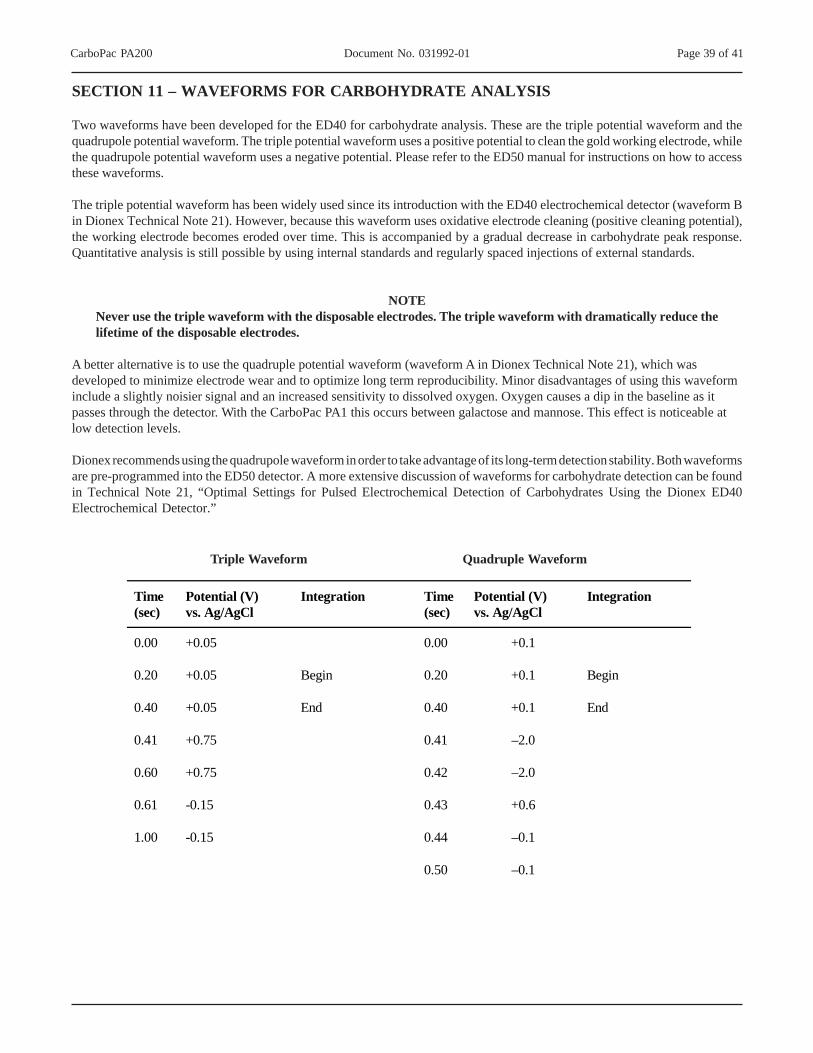
CarboPac PA200 Document No. 031992-01 Page 39 of 41
SECTION 11 – WAVEFORMS FOR CARBOHYDRATE ANALYSIS
Two waveforms have been developed for the ED40 for carbohydrate analysis. These are the triple potential waveform and thequadrupole potential waveform. The triple potential waveform uses a positive potential to clean the gold working electrode, whilethe quadrupole potential waveform uses a negative potential. Please refer to the ED50 manual for instructions on how to accessthese waveforms.
The triple potential waveform has been widely used since its introduction with the ED40 electrochemical detector (waveform Bin Dionex Technical Note 21). However, because this waveform uses oxidative electrode cleaning (positive cleaning potential),the working electrode becomes eroded over time. This is accompanied by a gradual decrease in carbohydrate peak response.Quantitative analysis is still possible by using internal standards and regularly spaced injections of external standards.
NOTENever use the triple waveform with the disposable electrodes. The triple waveform with dramatically reduce thelifetime of the disposable electrodes.
A better alternative is to use the quadruple potential waveform (waveform A in Dionex Technical Note 21), which wasdeveloped to minimize electrode wear and to optimize long term reproducibility. Minor disadvantages of using this waveforminclude a slightly noisier signal and an increased sensitivity to dissolved oxygen. Oxygen causes a dip in the baseline as itpasses through the detector. With the CarboPac PA1 this occurs between galactose and mannose. This effect is noticeable atlow detection levels.
Dionex recommends using the quadrupole waveform in order to take advantage of its long-term detection stability. Both waveformsare pre-programmed into the ED50 detector. A more extensive discussion of waveforms for carbohydrate detection can be foundin Technical Note 21, “Optimal Settings for Pulsed Electrochemical Detection of Carbohydrates Using the Dionex ED40Electrochemical Detector.”
Triple Waveform Quadruple Waveform
Time (sec)
Potential (V) vs. Ag/AgCl
Integration Time (sec)
Potential (V) vs. Ag/AgCl
Integration
0.00 +0.05 0.00 +0.1
0.20 +0.05 Begin 0.20 +0.1 Begin
0.40 +0.05 End 0.40 +0.1 End
0.41 +0.75 0.41 –2.0
0.60 +0.75 0.42 –2.0
0.61 -0.15 0.43 +0.6
1.00 -0.15 0.44 –0.1
0.50 –0.1

CarboPac PA200 Document No. 031992-01 Page 40 of 41
Table 3Comparison of the CarboPac PA100 and PA200 Columns
Characteristic CarboPac PA100 CarboPac PA200 Recommended Applications
Oligosaccharide mapping and analysis Higher resolution oligosaccharide mapping and analysis
Resin Composition Pellicular. 8.5 µm diameter ethylvinylbenzene/divinyl benzene substrate agglomerated with 275 nm MicroBead quaternary ammonium functionalized latex
Pellicular. 5.5 µm diameter ethylvinylbenzene/divinyl benzene substrate agglomerated with 43 nm MicroBead quaternary ammonium functionalized latex
Substrate X-linking 55% 55% Latex X-linking 6% cross-linked 6% cross-linked AE Capacity (4 x 250) 90 µeq 35 µeq Flow rate/min 1 mL (4-mm) 0.5 mL (3-mm) pH Compatibility pH 0–14 pH 0–14 Solvent Compatibility 0 < 90% 0–100% Max. Backpressure 4000 psi (28 MPa) 3500 psi (22 MPa)

CarboPac™ PA200 Date: 10-Mar-04 17:00
Analytical (3 X 250 mm) Serial No. : 000003
Product No. 062896 Lot No. : 014-01-086E
Flow Rate: 0.50 mL/min Eluent CompositionDetection: ED50 %A: 100 mM NaOH + 50 mM Sodium acetate
Temperature: 30°CInjection Volume: 10 µLDiluted Standard: 12 nmol/mL in DI Water
Each analyte is 0.12 nmolesper injection.
Storage Solution: Eluent
Quadruple WaveformTime Potential Integration0.00 0.100.20 0.10 Begin0.40 0.10 End0.41 -2.000.42 -2.000.43 0.600.44 -0.100.50 -0.10
Reference Electrode: Ag/AgClElectrode Mode: Ag
No. Peak Name Ret.Time Asymmetry Resolution Efficiency(min) (EP @ 10%) (EP) (EP)
1 Unknown 3.74 1.11 2.68 8076
2 alpha-(2,6)-NAN-Lac 4.15 1.01 2.05 14365
3 alpha-(2,3)-NAN-Lac 4.44 1.02 n.a. 14721
QA Results:Analyte Parameter Specification Results
alpha-(2,3)-NAN-Lac Efficiency >=10800 PASSalpha-(2,3)-NAN-Lac Asymmetry 1.00-1.54 PASSalpha-(2,3)-NAN-Lac Retention Time 4.17-4.83 PASS
Pressure <=2640 1740Production Reference:
Datasource: CON_SQL_local Sample No.: 1 6.50 SP3 Build 980
Sequence: CP_PA200 Chromeleon® Dionex Corp. 1996-2002
0.0 2.0 4.0 6.0 8.0 10.015.0
40.0
65.0 Serial No.: 3nC
min
1 2
3


![Research Paper Proteasome activator PA200 maintains ...the activator promotes the ubiquitin-dependent protein degradation [13]. PA200 and its yeast ortholog, Blm10, bind to the ends](https://img.pdfslide.us/doc/110x75/6119ed7d9e36c015a772f0c5/research-paper-proteasome-activator-pa200-maintains-the-activator-promotes-the.jpg)