Embed Size (px)
Citation preview
Energy Procedia
Energy Procedia 00 (2010) 000–000
www.elsevier.com/locate/XXX
Available online at www.sciencedirect.com
GHGT-10
Carbonate looping cycle for CO2 capture: Hydrodynamic of complex CFB systems
Ana Martínez, Pilar Lisbona, Yolanda Lara, Luis M. Romeo� Centre of Research for Energy Resources and Consumption (CIRCE), Thermal Division , Mariano Esquillor Gómez 15, Zaragoza 50018, Spain
Elsevier use only: Received date here; revised date here; accepted date here
Abstract
High temperature looping cycles, such as carbonation-calcination cycles based on calcium sorbents or chemical looping combustion are being developed and play an essential role in CO2 capture technologies. Among proposed configurations, outstanding schemes make use of a number of interconnected fluidized beds and may operate at bubbling or circulating regime. Fluidized bed behaviour is well-known since they are included in many industrial applications, such as power plants and chemical industries. However, there is a lack of knowledge about their operation when more than one fluidized bed are coupled in the same system. One promising configuration for Ca-based sorption looping systems relies on the use of two circulating beds as carbonator and calciner and two bubbling beds acting as loop-seal valves. Many theoretical and lab experimental studies point out the need of large solid circulation in the system to reach high carbonation efficiencies. The control of this flow in complex CFB looping systems, where also internal recirculation exists in the risers, becomes a difficult task and deserves further studies to characterize them. The challenge to solve, through experimental tests and mathematical modelling, is finding a comprehensive control method to operate two circulating beds in turbulent regime and two bubbling sealing devices. Experimental results supporting high carbonation efficiency or feasibility in scaling-up solid circulation rates and inventories are needed to make the system more reliable. A lab-scale cold flow facility has been designed based on Glicksman’s scaling rules and constructed in order to conduct experimental tests. The mechanical design of the facility and the choice of solid material, fluidizing gas and operating conditions should be such as to ensure the circulation of solids between reactors and the presence of solids inventory in the carbonator which are necessary to achieve high capture efficiencies. Operation of the system has been tested for a long number of hours under very different conditions. Measurements of circulation rate, static pressure, voidage profiles and standpipe height of solids have been used to identify trends in the hydrodynamic behaviour of the whole system while varying gas velocities in the risers, loop-seals, inventories in the reactors or size distribution of the particles. The circulation rates attained in the cold flow plant are comparable, after scaling-up, to solid flows in the loop which lead to high enough carbonation efficiencies of the system. © 2010 Elsevier Ltd. All rights reserved
Keywords: CO2 capture; carbonate looping cycle; CFB; scaling;
� Corresponding author. Tel.: +34-976-762-570; fax: +34-976-732-078. E-mail address: [email protected]
c⃝ 2011 Published by Elsevier Ltd.
Energy Procedia 4 (2011) 410–416
www.elsevier.com/locate/procedia
doi:10.1016/j.egypro.2011.01.069
2 Author name / Energy Procedia 00 (2010) 000–000
1. Introduction
In the last years the interest in CCS to reduce GHG emissions has increased significantly. This technique which provides low-emission energy generation has been pointed out by the IPCC as one of the solutions to limit climate change [1]. There are several approaches to separate CO2 from flue gas streams, a promising method for CO2 capture from flue gases is to use the carbonation/calcination reaction looping with Ca-based sorbents.
A dual fluidized bed system allows the separation of CO2 contained in flue gases by using the same circulating
sorbent during a number of carbonation/calcination cycles [2-5]. These systems have been extensively applied in adsorption processes and catalytic cracking [6]. Nowadays, their application in the GHG reduction also includes enhanced gasification [7] and chemical looping processes [8]. This configuration, dual circulating fluidized beds, seems to be the key technology to fulfil the carbonation/calcination looping process.
The overall system for the carbonation/calcination looping process consists of a carbonation and a calcination
reactor. In the first reactor, CaO is converted into CaCO3 at about 600-700 °C in the flue gases at atmospheric pressure. For continuous processes, the CO2 sorbents must be regenerated after the carbonation reaction to be used repeatedly. The CaCO3 is then removed from the carbonator and delivered to the regenerator. The calcination of CaCO3 regenerates the sorbent to CaO and produces a concentrated stream of CO2 at higher temperatures. A proper solid circulation rate is essential to achieve high capture efficiency. Hence, hydrodynamics play an important role and have to be studied.
This paper describes the design of a cold model facility that consists of two circulating fluidized beds and two
bubbling fluidized beds. Experimental tests have been carried out in the system. The results have been scaled in order to calculate the corresponding operation parameters in a real carbonation/calcination system.
2. Design and instrumentation of the experimental setup
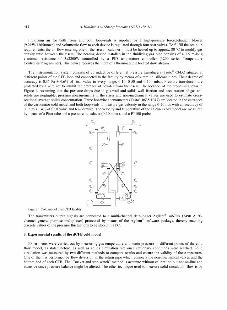
Figure 1 presents the cold model dual CFB system; this configuration was first proposed by Shimizu [9] to be applied to CO2 capture. Both CFB’s – carbonator and calciner – built from Plexiglas® to favor particle visualization are 4 m high and 0.17 and 0.16 m i.d. respectively. As a consequence of the construction material, particles may suffer electrostatic charging altering hydrodynamic behaviour. To reduce this problem, risers have been covered with a blind flange which provides grounding. Air distributor plates of the circulating fluidized beds are built with a series of flat metallic meshes and a typical perforated plate type, the diameter of pores ranges from 80 to 1000 �m. The pressure drop generated by these distributors is 1.5-4.5 mbar (approximately 4-10% of the total pressure drop in the circulating fluidized bed, depending on inventory), high enough to ensure the proper regime in the reactor for the solid inventories fed into the system [10]. Exit region of these reactors are clasified as “abrupt” [11] and connect horizontally the upper part of the riser and the solid separator unit. The cyclones are designed according the high efficiency Muschelnautz design [12] to retain the 99.9% of solid particles passing through. For safety reasons, bag-filters (pore diameter 8 �m) are also installed downstream the cyclones to retain the fine particles generated by attrition or contained in the initial mixture.
Solid flow separated in the cyclones falls down through a standpipe into the corresponding loop-seal. These non-
mechanical valves control particles flux with no moving parts which reduces operating problems. Recycle systems include a 0.08 m i.d. 1.447 m high standpipe, a 0.177 m i.d. 0.3 m high cylindrical loop-seal and a return pipe made of translucent flexible plastic. The non-mechanical valve provides the pressure seal required for the solids to flow from the relatively low pressure region near the outlet of the circulating bed to a higher pressure region at the bottom. Both loop-seals have two exits to allow the diversion of particle circulation. Air distributor plates in the bubbling fluidized bed need higher pressure drop in the distributor to avoid preferential paths and ensure a proper operation [10]. Therefore, the solids distributor plates of the non-mechanical valves have, besides the metallic perforated plate, several slides of punched polyester that generate a pressure drop of 5-15 mbar (13-30% of the total pressure drop in the bubbling fluidized bed, including the distributor) for superficial velocities ranging from 0.05 to 0.1 m/s.
A. Martı́nez et al. / Energy Procedia 4 (2011) 410–416 411
Author name / Energy Procedia 00 (2010) 000–000 3
Fluidizing air for both risers and both loop-seals is supplied by a high-pressure forced-draught blower
(9.2kW/1365mmca) and volumetric flow to each device is regulated through four seat valves. To fulfill the scale-up requirements, the air flow entering one of the risers – calciner – must be heated up to approx. 80 ºC to modify gas density ratio between the risers. The heating device installed in the fluidizing gas pipe consists of a 1.5 m-long electrical resistance of 3x2200W controlled by a PID temperature controller (3200 series Temperature Controller/Programmer). This device receives the input of a thermocouple located downstream.
The instrumentation system consists of 25 inductive differential pressure transducers (Testo® 634X) situated at
different points of the CFB loop and connected to the facility by means of 4 mm i.d. silicone tubes. Their degree of accuracy is 0.35 Pa + 0.6% of final value in every range, 0-10, 0-50 and 0-100 mbar. Pressure transducers are protected by a wire net to inhibit the entrance of powder from the risers. The location of the probes is shown in Figure 1. Assuming that the pressure drops due to gas-wall and solids-wall friction and acceleration of gas and solids are negligible, pressure measurements in the risers and non-mechanical valves are used to estimate cross-sectional average solids concentration. Three hot-wire anemometers (Testo® 0635 1047) are located in the entrances of the carbonator cold model and both loop-seals to measure gas velocity in the range 0-20 m/s with an accuracy of 0.03 m/s + 4% of final value and temperature. The velocity and temperature of the calciner cold model are measured by means of a Pitot tube and a pressure transducer (0-10 mbar), and a PT100 probe.
Figure 1 Cold model dual CFB facility.
The transmitters output signals are connected to a multi-channel data-logger Agilent® 34670A (34901A 20-channel general purpose multiplexer) processed by means of the Agilent® software package, thereby enabling discrete values of the pressure fluctuations to be stored in a PC.
3. Experimental results of the dCFB cold model
Experiments were carried out by measuring gas temperature and static pressure in different points of the cold flow model, as stated before, as well as solids circulation rate once stationary conditions were reached. Solid circulation was measured by two different methods to compare results and ensure the validity of these measures. One of them is performed by flow diversion in the return pipe which connects the non-mechanical valves and the bottom bed of each CFB. The “Bucket and stop watch” method is accurate without calibration but not on-line and intrusive since pressure balance might be altered. The other technique used to measure solid circulation flow is by
412 A. Martı́nez et al. / Energy Procedia 4 (2011) 410–416
4 Author name / Energy Procedia 00 (2010) 000–000
stopping loop-seal aeration, the solid circulation may be measured through the increase of solid height in the standpipe and the time of the measurement since the apparent density in the standpipe has been previously calculated.
The independent parameters are the total riser fluidization, the solid inventory of the whole system, solid
inventory distribution between the risers, loop-seal aeration and standpipe solid height. Also the effect of particle size distribution of the solid population is observed.
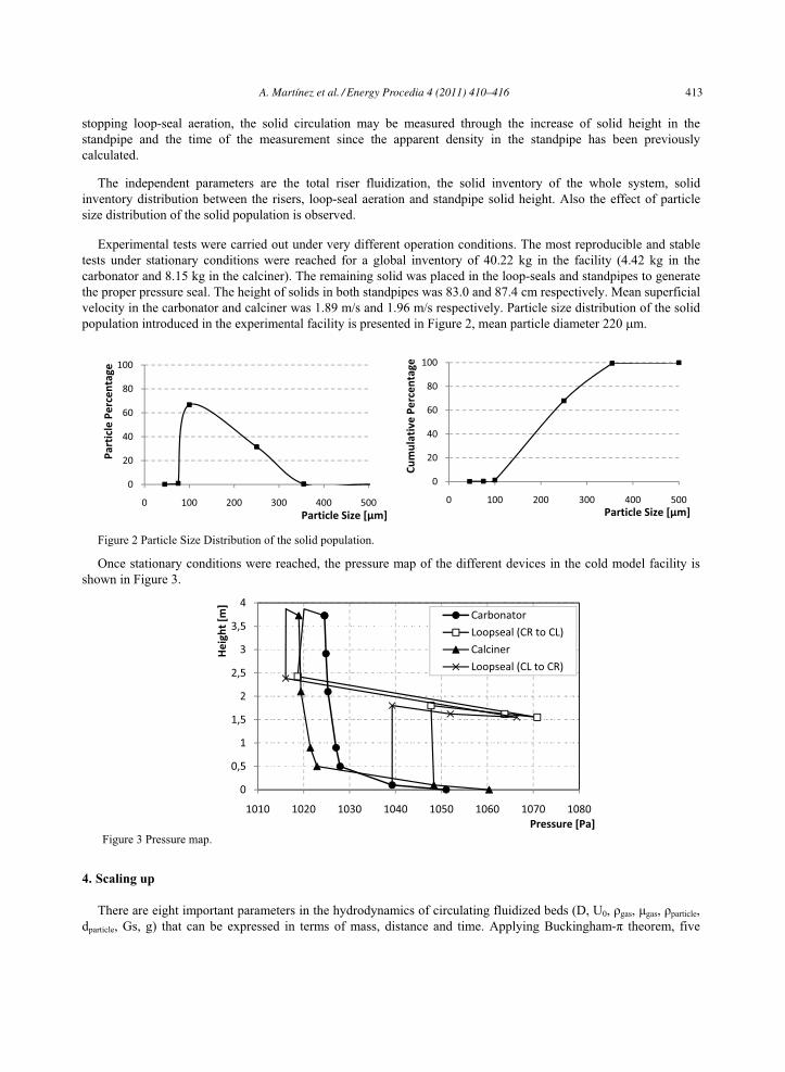
Experimental tests were carried out under very different operation conditions. The most reproducible and stable
tests under stationary conditions were reached for a global inventory of 40.22 kg in the facility (4.42 kg in the carbonator and 8.15 kg in the calciner). The remaining solid was placed in the loop-seals and standpipes to generate the proper pressure seal. The height of solids in both standpipes was 83.0 and 87.4 cm respectively. Mean superficial velocity in the carbonator and calciner was 1.89 m/s and 1.96 m/s respectively. Particle size distribution of the solid population introduced in the experimental facility is presented in Figure 2, mean particle diameter 220 �m.
�
�
�� �� �� �� �� �� �� �� ��
�� �� �� �� �� �� �� �� �� ���� �� �� �� �� �� �� �� �� ���� �� �� �� �� �� �� �� �� ���� �� �� �� �� �� �� �� �� ���� �� �� �� �� �� �� �� �� ���� �� �� �� �� �� �� �� �� ���� �� �� �� �� �� �� �� �� ��
Figure 2 Particle Size Distribution of the solid population.
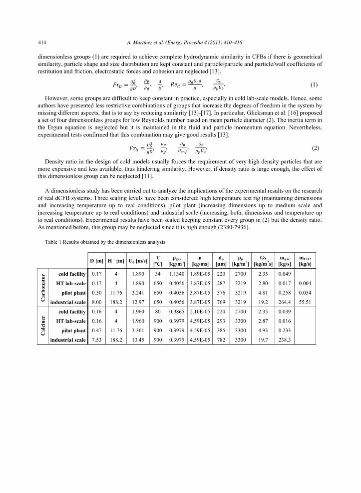
Once stationary conditions were reached, the pressure map of the different devices in the cold model facility is shown in Figure 3.
�
�
� � � � � �
Figure 3 Pressure map.
4. Scaling up
There are eight important parameters in the hydrodynamics of circulating fluidized beds (D, U0, �gas, �gas, �particle, dparticle, Gs, g) that can be expressed in terms of mass, distance and time. Applying Buckingham-� theorem, five
0
20
40
60
80
100
0 100 200 300 400 500
Cumulative�Pe
rcen
tage
Particle�Size�[�m]
0
20
40
60
80
100
0 100 200 300 400 500
Particle�Percentage
Particle�Size�[�m]
0
0,5
1
1,5
2
2,5
3
3,5
4
1010 1020 1030 1040 1050 1060 1070 1080
Height�[m]
Pressure�[Pa]
Carbonator
Loopseal�(CR�to�CL)
Calciner
Loopseal�(CL�to�CR)
A. Martı́nez et al. / Energy Procedia 4 (2011) 410–416 413
Author name / Energy Procedia 00 (2010) 000–000 5
dimensionless groups (1) are required to achieve complete hydrodynamic similarity in CFBs if there is geometrical similarity, particle shape and size distribution are kept constant and particle/particle and particle/wall coefficients of restitution and friction, electrostatic forces and cohesion are neglected [13].
��� ����
�,
�
�,
�, �� �
���
�,
��
���, (1)
However, some groups are difficult to keep constant in practice, especially in cold lab-scale models. Hence, some authors have presented less restrictive combinations of groups that increase the degrees of freedom in the system by missing different aspects, that is to say by reducing similarity [13]-[17]. In particular, Glicksman et al. [16] proposed a set of four dimensionless groups for low Reynolds number based on mean particle diameter (2). The inertia term in the Ergun equation is neglected but it is maintained in the fluid and particle momentum equation. Nevertheless, experimental tests confirmed that this combination may give good results [13].
��� ����
�,
�
�, ��
���, ��
���, (2)
Density ratio in the design of cold models usually forces the requirement of very high density particles that are more expensive and less available, thus hindering similarity. However, if density ratio is large enough, the effect of this dimensionless group can be neglected [11].
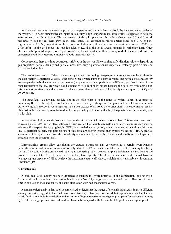
A dimensionless study has been carried out to analyze the implications of the experimental results on the research
of real dCFB systems. Three scaling levels have been considered: high temperature test rig (maintaining dimensions and increasing temperature up to real conditions), pilot plant (increasing dimensions up to medium scale and increasing temperature up to real conditions) and industrial scale (increasing, both, dimensions and temperature up to real conditions). Experimental results have been scaled keeping constant every group in (2) but the density ratio. As mentioned before, this group may be neglected since it is high enough (2380-7936).
Table 1 Results obtained by the dimensionless analysis.
D [m] H [m] U0 [m/s] T
[ºC] �gas
[kg/m3]�
[kg/ms] dp
[�m] �p
[kg/m3]Gs
[kg/m2s] mgas
[kg/s] mCO2 [kg/s]
Car
bona
tor cold facility 0.17 4 1.890 34 1.1340 1.89E-05 220 2700 2.35 0.049
HT lab-scale 0.17 4 1.890 650 0.4056 3.87E-05 287 3219 2.80 0.017 0.004
pilot plant 0.50 11.76 3.241 650 0.4056 3.87E-05 376 3219 4.81 0.258 0.054
industrial scale 8.00 188.2 12.97 650 0.4056 3.87E-05 769 3219 19.2 264.4 55.51
Cal
cine
r
cold facility 0.16 4 1.960 80 0.9865 2.10E-05 220 2700 2.35 0.039
HT lab-scale 0.16 4 1.960 900 0.3979 4.59E-05 293 3300 2.87 0.016
pilot plant 0.47 11.76 3.361 900 0.3979 4.59E-05 385 3300 4.93 0.233
industrial scale 7.53 188.2 13.45 900 0.3979 4.59E-05 782 3300 19.7 238.3
414 A. Martı́nez et al. / Energy Procedia 4 (2011) 410–416
6 Author name / Energy Procedia 00 (2010) 000–000
As chemical reactions have to take place, gas properties and particle density should be independent variables of
the system. Also risers dimensions are inputs in this study. High temperature lab-scale utility is supposed to have the same geometry as the cold one. The carbonators of the pilot plant and the industrial-scale are 0.5 and 8 m i.d. respectively, and the calciners grow in the same ratio. The carbonation reaction takes place at 650 ºC and the regeneration at 900 ºC, both at atmospheric pressure. Calcium oxide and calcium carbonate densities are 3300 and 2700 kg/m3. In the cold model no reaction takes place, thus the solid stream remains in carbonate form. Once chemical adsorption-desorption of CO2 is considered, the calcined solid flow is composed of calcium oxide and the carbonated solid flow presents a mixture of both chemical species.
Consequently, there are three dependent variables in the system. Since minimum fluidization velocity depends on
gas properties, particle density and particle mean size, output parameters are superficial velocity, particle size and solids circulation flux.
The results are shown in Table 1. Operating parameters in the high temperature lab-scale are similar to those in
the cold facility. Superficial velocity is the same. Since Froude number is kept constant, and particle size and density are comparable in both cases. As gas properties (temperature and composition) are different, gas flux is lower in the high temperature facility. However, solid circulation rate is slightly higher because the solid/gas volumetric flux ratio remains constant and calcium oxide is denser than calcium carbonate. This facility could capture the CO2 of a 20 kW test rig.
The superficial velocity and particle size in the pilot plant is in the range of typical values in commercial
circulating fluidized beds [11]. This facility can process nearly 0.26 kg/s of flue gases with a solid circulation rate close to 5 kg/m2s. Hence, it could separate the carbon dioxide of a 250-350 kW pilot plant. The experimental results obtained in the cold facility may be used in the design and operation of both a high temperature lab-scale facility and a pilot plant.
As mentioned before, results have also been scaled for an 8 m i.d. industrial scale plant. This system corresponds
to around a 300 MW power plant. Although risers are too high due to geometric similarity, lower reactors may be adequate if transport disengaging height (TDH) is exceeded, since hydrodynamics remain constant above this point [18]. Superficial velocity and particle size in this scale are slightly greater than typical values in CFBs. A gradual scaling-up of the system increases the probability of agreement between the experimental results and the hypothesis obtained from the previous level.
Dimensionless groups allow calculating the capture parameters that correspond to a certain hydrodynamic
parameters in the cold model. A sorbent to CO2 ratio of 12.42 has been calculated for the three scaling levels, by means of the solid circulation rate and the CO2 flux entering the carbonator. Capture efficiency is calculated as the product of sorbent to CO2 ratio and the sorbent capture capacity. Therefore, the calcium oxide should have an average capture capacity of 8% to achieve the maximum capture efficiency, which is easily attainable with common limestones [19].
5. Conclusions
A cold dual CFB facility has been designed to analyze the hydrodynamics of the carbonation looping cycle. Proper and stable operation of the system has been confirmed by long-term experimental results. However, it takes time to gain experience and control the solid circulation with non-mechanical valves.
A dimensionless analysis has been accomplished to determine the values of the main parameters in three different
scaling levels (test rig, pilot plant, and commercial facility). It has been concluded that experimental results obtained in this facility may help in the design and operation of high temperature test rig and pilot plant for carbonate looping cycle. The scaling-up to commercial facilities have to be analysed with the results of large dimensions pilot plant.
A. Martı́nez et al. / Energy Procedia 4 (2011) 410–416 415
Author name / Energy Procedia 00 (2010) 000–000 7
Further tests are needed to gain experience in the control and operation of the solid circulation of this systems. This variable is the key to achieve good capture efficiencies and low capture costs in calcium cycle and chemical looping applications.
Acknowledgement
The work described in this paper was supported by the R+D Spanish National Program from Ministerio de Ciencia e Innovación, MICINN (Spanish Ministry of Science and Innovation) under project ENE2009-08246. Financial support for A. Martínez during her Ph.D. studies was provided by the FPU programme of the Spanish Ministry of Science and Innovation.
References
[1] Metz B, Davidson O, de Connick H, Loos M, Meyer L, Eds. Special Report on Carbon Dioxide Capture and Storage. Technical Report; 2005.
[2] Romeo LM, Abanades JC, Escosa JM, Paño J, Giménez A, Sanchez-Biezma A, Ballesteros JC. Oxyfuel carbonation/calcination cycle for low cost CO2 capture in existing power plants. Energ Convers Manage 2008;49:2809–14
[3] Abanades JC, Alonso M, Rodriguez N. Experimental validation of in situ CO2 capture with CaO during the low temperature combustion of biomass in a fluidized bed reactor. Int J Greenh Gas Con 2010; doi:10.1016/j.ijggc.2010.01.006
[4] Blamey J, Anthony EJ, Wang J, Fennell PS. The calcium looping cycle for large-scale CO2 capture. Prog Energ Combust 2010;36:260-79
[5] Romeo LM, Lara Y, Lisbona P, Escosa JM. Optimizing make-up flow in a CO2 capture system using CaO. Chem Eng J 2009;147:252–8
[6] Grace JR, High-velocity fluidized bed reactors. Chem Eng Sci 1990; 45; 1953-66; [7] Lisbona P, Romeo LM. Enhanced coal gasification heated by unmixed combustion integrated with an hybrid
system of SOFC/GT. Int J Hydrogen Energ 2008; 33; 5755-64 [8] Abad A, Adánez J, García-Labiano F, de Diego LF, Gayán P. Modeling of the chemical-looping combustion of
methane using a Cu-based oxigen-carrier. Combust Flame 2010; 157; 602-15 [9] Shimizu T, Hirama T, Hosoda H, Kitano K, Inagaki M, Tejima K. A twin fluid-bed reactor for removal of CO2
from combustion processes. Chem Eng Res Des 1999; 77:62-8 [10] Svensson A, Johnson F, Leckner B. Fluidization regimes in non-slugging fluidized beds: the influence of
pressure drop across the air distributor. Powder Technol 1996; 86:299-12 [11] Grace JR, Avidan AA, Knowlton TM. Circulating Fluidized Beds, London: Blackie Academic and
Professional; 1997. [12] Hoffman AC, Stein LE. Gas cyclones and swirl tubes: principles, design and operation. Berlin: Springer; 2002. [13] Van der Meer EH, Thorpe RB, Davidson JF. Dimensionless groups for practicable similarity of circulating
fluidized beds, Chem Eng Sci 1999; 54:5369-76. [14] Horio M, Nonaka A, Sawa Y, Muchi I. A new similarity rule for fluidized bed scale-up, AIChE J 1986;
32:1466-82. [15] Glicksman LR. Scaling relationships for fluidized beds. Chem Eng Sci 1988; 43:1419-21. [16] Glicksman LR, Hyre M, Woloshun K. Simplified scaling relationships for fluidized beds. Powder Technol
1993; 77:177-99. [17] Horio M, Ishii H, Kobukai Y, Yamanishi N. A scaling law of circulating fluidized beds. J Chem Eng Jpn 1989;
22(6):587-92. [18] Kunii D, Levenspiel O. Fluidization Engineering. 2nd ed. Butterworth-Heinemann; 1991. [19] Lisbona P, Martínez A, Lara Y, Romeo LM. Integration of Carbonate CO2 Capture Cycle and Coal-Fired Power
Plants. A Comparative Study for Different Sorbents. Energ Fuel 2010; 24; 728-36
416 A. Martı́nez et al. / Energy Procedia 4 (2011) 410–416