Embed Size (px)
Citation preview

Birck Nanotechnology Center Nanoscale Transport Research Group 1
ECET499 Guest Lecture
Sungwon S. Kim, Ph.D.Visiting Assistant Professor
Birck Nanotechnology Center and School of Mechanical EngineeringPurdue University
March 4th, 2010
Carbon Nanotubes: Synthesis and Applications

Birck Nanotechnology Center Nanoscale Transport Research Group 2
Overview
• Nanotechnology
• CNT Synthesis
• CNT Applications
• My Perspective

Birck Nanotechnology Center Nanoscale Transport Research Group 3
Nanotechnology
• Study of materials and phenomena at nanoscale
• National Nanotechnology Initiative (NNI)– Launched in 2001 to coordinate research activities
• Birck Nanotechnology Center– $58 million facility opened in 2005
– 187,000 ft2 of space, 25,000 ft2 cleanroom
– Over 45 faculty members and 145 students
Birck Nanotechnology Center Nanoscale Transport Research Group 4
Nanotechnology

Birck Nanotechnology Center Nanoscale Transport Research Group 5
Nanotechnology

Birck Nanotechnology Center Nanoscale Transport Research Group 6
Nanotechnology• Carbon nanotubes (CNTs)
Diamond Graphite
C60
Carbon chain
C70 CNThttp://www.seed.slb.com/en/scictr/watch/fullerenes/index.htm

Birck Nanotechnology Center Nanoscale Transport Research Group 7
Carbon Nanotubes (CNTs)• Timeline
1985 Discovery of Fullerenes R. E. Smalley et al., Nature, 318, 162 (1985)
1991 Discovery of MWNTs S. Iijima et al., Nature 354, 56 (1991)
1992 Conductivity of CNTs C. T. White et al., Phys. Rev. Lett. 68, 631 (1992)
1993 Structural rigidity of CNTs D. Tománek et al., Z. Phys. D 27, 93 (1993)
1993 Synthesis of SWNTs S Iijima, T Ichihashi et al. Nature, 363, 603 (1993)
1995 Nanotubes as field emitters R. E. Smalley et al., Science 269, 1550 (1995)
1996 Ropes of SWNTs R. E. Smalley et al., Science 273, 483 (1996).
1997 Quantum conductance of CNTs C Dekker et al., Nature, 386, 474 (1997)
1997 Hydrogen storage in CNTs M J Heben et al., Nature, 386, 377 (1997)
1998 CVD synthesis of aligned CNT films Z F Ren et al., Science, 282, 1105 (1998)

Birck Nanotechnology Center Nanoscale Transport Research Group 8
Carbon Nanotubes (CNTs)• Timeline
2000 Thermal conductivity of CNTs D. Tománek et al., Phys. Rev. Lett. 84, 4613 (2000)
2000 Macroscopically aligned CNTs P. Poulin et al., Science 290, 1331 (2000)
2001 Intrinsic superconductivity of CNTs H. Bouchiat et al., Phys. Rev. Lett. 86, 2416 (2001)
2001 Integration of CNTs for logic circuits P. Avouris et al., Science 292, 706 (2001)
2003 Ballistic CNT field effect transistor H. Dai et al., Nature 424, 654 (2003)
2004 Nanotube molecular transporter H. Dai et al., JACS, 126, 6850 (2004)
2006 Nanotube-based sensor M. Strano et al. Science 311, 508 (2006)
Recommended review book: Carbon Nanotubes: Synthesis, Structure, Properties, and Applicationsby M. S. Dresselhaus, G. Dresselhaus, and P. Avouris

Birck Nanotechnology Center Nanoscale Transport Research Group 9
Carbon Nanotubes (CNTs)• Structure
– Formed from the hexagonal graphene carbon structure
– Can form single-wall (SWNT) or multi-wall (MWNT) structures
– Ends (tips) can be open or closed (capped)
– High aspect ratio (length = ~1000 x diameter)

Birck Nanotechnology Center Nanoscale Transport Research Group 10
Carbon Nanotubes (CNTs)• Properties
– Mechanical: Young’s modulus ~1 TPa (5X steel) (Treacy et al. 1996)
– Electrical: Metallic or semiconductor behavior, depending on wall structure of SWNTs, and high conductivity
– Thermal: Room-temperature thermal conductivity 3000 W/mK (8X copper) - similar to diamond
– Chemical: high storage capacity

Birck Nanotechnology Center Nanoscale Transport Research Group 11
Overview
• Nanotechnology
• CNT Synthesis
• CNT Applications
• My Perspective

Birck Nanotechnology Center Nanoscale Transport Research Group 12
CNT Synthesis• Heterogeneous catalysis
– Carbon atoms: gas to solid
– Catalyst precursor metal deposition• E-beam evaporation at 7x10⁻⁷ Torr
• 20nm Cr underlayer used for adhesion and prevention of catalyst poisoning
• Varying Ni catalyst thicknesses: 5nm, 10nm, 20nm
SiCr
Ni

Birck Nanotechnology Center Nanoscale Transport Research Group 13
CNT Synthesis• Fe/dendrimer catalyst (wet chemistry based)Fe3+/G4-NH2composite
Fe2O3 nanoparticles
Amama, et al., 2006, "Dendrimer-templated Fe nanoparticles for the growth of single-wall carbon nanotubes by plasma-enhanced CVD", Journal of Physical Chemistry B, Vol.110, pp. 10636-10644.
AFM images of Fe2O3 nanoparticles

Birck Nanotechnology Center Nanoscale Transport Research Group 14
MPCVD System
1.5kW and 2.5GHzMicrowave generator
Dual wavelengthpyrometer
Vacuum chamber
75 mm of stage translation
Seki Technotron Corp.AX5200 Series
H2 – 1000cm3/minCH4 - 10cm3/min
DC bias:0 – 600 V; 0 – 1.7 A
Stage temperature control with heating
up to 1000˚C

Birck Nanotechnology Center Nanoscale Transport Research Group 15
MPCVD System
Plasma
Suceptor
RF Power Supply
Pump
CH4 H2 N2
Microwave Generator
Puck
Cooling Water Line
Loading Window
Mass Flow Controllers
Birck Nanotechnology Center Nanoscale Transport Research Group 16
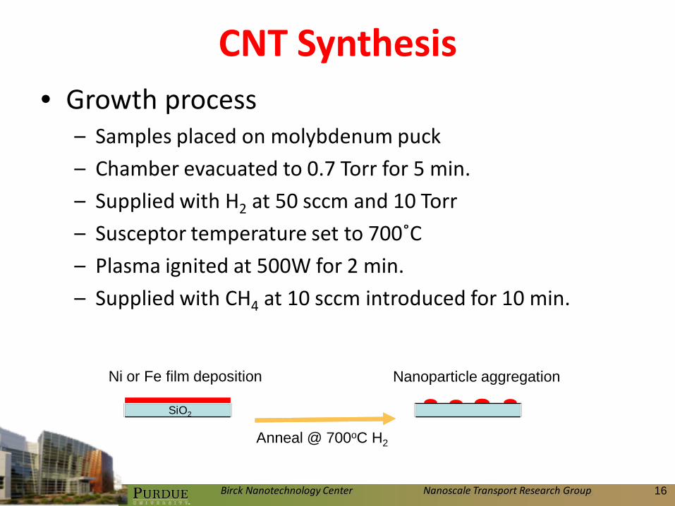
CNT Synthesis• Growth process
– Samples placed on molybdenum puck
– Chamber evacuated to 0.7 Torr for 5 min.
– Supplied with H2 at 50 sccm and 10 Torr
– Susceptor temperature set to 700˚C
– Plasma ignited at 500W for 2 min.
– Supplied with CH4 at 10 sccm introduced for 10 min.
Nanoparticle aggregation
Si(100)
SiO2
Ni or Fe film deposition
Anneal @ 700oC H2
Nanoparticle aggregation
Si(100)
SiO2
Ni or Fe film deposition
Anneal @ 700oC H2

Birck Nanotechnology Center Nanoscale Transport Research Group 17
CNT Synthesis

Birck Nanotechnology Center Nanoscale Transport Research Group 18
SiO2
Ti layer
Fe2O3nanoparti
cles
CNT Synthesis
Fe Ni Co

Birck Nanotechnology Center Nanoscale Transport Research Group 19
CNT Synthesis
100 nm
10 nm
10 nm
200 nm
250°C, 0V 900°C, 0V
250°C, 0V
900°C, 0V 250°C, 0V 900°C, 0V

Birck Nanotechnology Center Nanoscale Transport Research Group 20
Effects of Inlet Gas Compositionon MWCNT Diameter
0 5 10 15 200
10
20
30
40
50
60Di
amet
er [n
m]
Inlet CH4 Volume Fraction [%]
20nm Ni Catalyst 10nm Ni Catalyst 5nm Ni Catalyst
Garg, Kim et al., “Effects of Feed Gas Composition and Catalyst Thickness on Carbon Nanotube and Nanofiber Synthesis by Plasma Enhanced Chemical Vapor Deposition”, Journal of Nanoscience and Nanotechnology, 2008.

Birck Nanotechnology Center Nanoscale Transport Research Group 21
0 5 10 15 200
10
20
30
40
50
60Di
amet
er [n
m]
Ni Catalyst Thickness [nm]
5.9% CH4 11.1% CH4 20% CH4
Effects of Catalyst Layer Thicknesson MWCNT Diameter
Garg, Kim et al., “Effects of Feed Gas Composition and Catalyst Thickness on Carbon Nanotube and Nanofiber Synthesis by Plasma Enhanced Chemical Vapor Deposition”, Journal of Nanoscience and Nanotechnology, 2008.

Birck Nanotechnology Center Nanoscale Transport Research Group 22
Overview
• Nanotechnology
• CNT Synthesis
• CNT Applications
• My Perspective

Birck Nanotechnology Center Nanoscale Transport Research Group 23
CNT Applications• Biosensor material
– Enzymatic biosensors: immobilization of enzyme on CNTs
– Glucose / glucose oxidase• Electrons formed and collected amperometric
e-
glucosegluconicacid
Pt
Schematic diagram of the glucose/glucose oxidase reaction (adapted from Sotiropoulou and Chaniotakis, 2003).

Birck Nanotechnology Center Nanoscale Transport Research Group 24
CNT Applications• Integration of CNT sample with PDMS cell

Birck Nanotechnology Center Nanoscale Transport Research Group 25
Fluorescence intensity result for BSA-FITC immobilized Sample #1 - #3
0 100 200 300 400 500 600 700 800 900 10000
1000
2000
3000
4000
5000
6000
7000
8000
9000
10000
Num
ber o
f Pix
els
Fluorescence Intensity [A.U.]
Sample #1 - autofluorescence check - 1sec exp Sample #1 - FITC BSA - 1 sec exp Sample #2 - autofluorescence check - 1sec exp Sample #2 - FITC BSA - 1 sec exp Sample #3 - autofluorescence check - 1sec exp Sample #3 - FITC BSA - 1 sec exp
Sample 1
Sample 2
Sample 3
-100V Bias
Kim et al., “Effects of Carbon Nanotube Structure on Protein Adsorption”, Proceedings of International Mechanical Engineering Congress and Exposition 2005, IMECE2005-81391, Orlando, Florida, USA.
Protein Adsorption on CNTs

Birck Nanotechnology Center Nanoscale Transport Research Group 26
Protein Adsorption on CNTs
10 μm
10 μm
10 μm
10 μm
10 μm
10 μm
10 μm
10 μm
10 μm
10 μm
10 μm
10 μm
10 μm
10 μm
10 μm
10 μm
0V -100V -200V -300V
250 °C 550 °C
700 °C 900 °C

Birck Nanotechnology Center Nanoscale Transport Research Group 27
Characterization: SEMs• Estimation of CNT surface area
d s
h

Birck Nanotechnology Center Nanoscale Transport Research Group 28
Characterization: Raman Spectroscopy
1000 1200 1400 1600 1800 2000
0
500
1000
1500
2000
2500
3000
3500 0V, 250oC
Inte
nsity
[A.U
.]
Raman Shift [cm-1]1000 1200 1400 1600 1800 2000
0
1000
2000
3000
4000
5000
6000
7000 0V, 550oC
Inte
nsity
[A.U
.]
Raman Shift [cm-1]
1000 1200 1400 1600 1800 2000
0
2000
4000
6000
8000
10000
12000
Raman Shift [cm-1]
0V, 700oC
Inte
nsity
[A.U
.]
1000 1200 1400 1600 1800 2000
0
2000
4000
6000
8000
10000 0V, 900oC
Inte
nsity
[A.U
.]
Raman Shift [cm-1]
D-band peak at around 1300 cm-
1 (amorphous carbon)
G-band peak at around 1600 cm-
1 (well graphitized structure)
Intensity of the G-band relative to the D-band (IG/ID) calculated to assess quality of CNTs (Amama et al.,
2007, Eklund et al., 1995)

Birck Nanotechnology Center Nanoscale Transport Research Group 29
Current per CNT Area vs Raman
0.3 0.4 0.5 0.6 0.7 0.8
0.0
1.0x10⁻⁸
2.0x10⁻⁸
3.0x10⁻⁸
4.0x10⁻⁸
5.0x10⁻⁸ 0V Bias -100V Bias -200V Bias -300V Bias
Curre
nt p
er C
NT A
rea
[A/m
m2 ]
IG/ ID RatioKim et al., 2009, “Preferential Biofunctionalization of Carbon Nanotubes Grown by Microwave
Plasma-Enhanced CVD”, submitted to Journal of Physical Chemistry C.

Birck Nanotechnology Center Nanoscale Transport Research Group 30
Protein Adsorption on CNTs
Birck Nanotechnology Center Nanoscale Transport Research Group 31
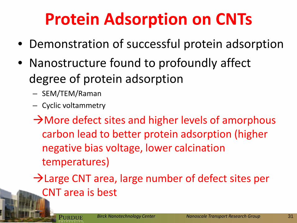
Protein Adsorption on CNTs• Demonstration of successful protein adsorption
• Nanostructure found to profoundly affect degree of protein adsorption– SEM/TEM/Raman
– Cyclic voltammetry
More defect sites and higher levels of amorphous carbon lead to better protein adsorption (higher negative bias voltage, lower calcination temperatures)
Large CNT area, large number of defect sites per CNT area is best

Birck Nanotechnology Center Nanoscale Transport Research Group 32
CNT Applications• Vapor chambers
– Phase change phenomena
– Wicking of working fluid
– Micrometer sized mesh
BULK FEEDING WICK
METALLIZED CNT EVAPORATOR
Kim, Weibel et al., 2010, “Thermal Performance of Carbon Nanotube Enhanced Vapor Chamber Wicks”, submitted to 14th International Heat Transfer Conference.

Birck Nanotechnology Center Nanoscale Transport Research Group 33
CNT Applications• Why CNTs?
– Good thermal interface characteristics
– High inherent thermal conductivity
– Wicking capability• Thinning out of liquid layer for improved evaporation
Substrate
LiquidCNTs
Kim, Weibel et al., 2010, “Thermal Performance of Carbon Nanotube Enhanced Vapor Chamber Wicks”, submitted to 14th International Heat Transfer Conference.

Birck Nanotechnology Center Nanoscale Transport Research Group 34
Vapor Chamber Wicks• Integration of copper mesh with Cu-Mo-Cu
substrate
• Catalyst metal deposition
• Growth of CNTs in MPCVD
Kim, Weibel et al., 2010, “Thermal Performance of Carbon Nanotube Enhanced Vapor Chamber Wicks”, submitted to 14th International Heat Transfer Conference.

Birck Nanotechnology Center Nanoscale Transport Research Group 35
Vapor Chamber Wicks(a) (b)
(c) (d)
Kim, Weibel et al., 2010, “Thermal Performance of Carbon Nanotube Enhanced Vapor Chamber Wicks”, submitted to 14th International Heat Transfer Conference.

Birck Nanotechnology Center Nanoscale Transport Research Group 36
Vapor Chamber Wicks

Birck Nanotechnology Center Nanoscale Transport Research Group 37
Vapor Chamber Wicks
Kim, Weibel et al., 2010, “Thermal Performance of Carbon Nanotube Enhanced Vapor Chamber Wicks”, submitted to 14th International Heat Transfer Conference.
• Thermal performance

Birck Nanotechnology Center Nanoscale Transport Research Group 38
Vapor Chamber Wicks• Thermal performance
– Effective in dissipating upwards of 500 W/cm2 at low levels of superheat without any observed dryout or CHF
– Positive bias, nominal thickness of Cu coating strongly influence level of superheat and wick thermal resistance
denser growth of CNTs, thicker Cu coating leading to better performance

Birck Nanotechnology Center Nanoscale Transport Research Group 39
Overview
• Nanotechnology
• CNT Synthesis
• CNT Applications
• My Perspective

Birck Nanotechnology Center Nanoscale Transport Research Group 40
My Perspective• Mechanical engineering
– Ph.D., Purdue University, 2008
– M.S., KAIST, 2002
– B.S., Korea University, 2000
• Engineering devices using CNTs– Performance is driven by structure
– Ability to control structure
Growth Parameters CNT Structure Function

Birck Nanotechnology Center Nanoscale Transport Research Group 41
My Perspective• Challenges
– Mass production
– Characterization of properties
– Increased control over geometry
– Optimization of growth parameters
– Integration with engineering devices
Growth Parameters CNT Structure Function

Birck Nanotechnology Center Nanoscale Transport Research Group 42
Thank you!!
Questions ?
Comments !