Embed Size (px)
Citation preview
This article was downloaded by: [University of Washington Libraries]On: 26 October 2014, At: 04:38Publisher: Taylor & FrancisInforma Ltd Registered in England and Wales Registered Number: 1072954 Registeredoffice: Mortimer House, 37-41 Mortimer Street, London W1T 3JH, UK
Nanoscience MethodsPublication details, including instructions for authors andsubscription information:http://www.tandfonline.com/loi/tnme20
Carbon nanotube-filled conductiveadhesives for electronic applicationsIrfan Ahmad Mir a & D. Kumar aa Department of Applied Chemistry & Polymer Technology , DelhiTechnological University (Delhi College of Engineering) , ShahbadDaulatpur, Bawana Road, Delhi , 110042 , IndiaPublished online: 12 Sep 2012.
To cite this article: Irfan Ahmad Mir & D. Kumar (2012) Carbon nanotube-filled conductiveadhesives for electronic applications, Nanoscience Methods, 1:1, 183-193, DOI:10.1080/17458080.2011.602724
To link to this article: http://dx.doi.org/10.1080/17458080.2011.602724
PLEASE SCROLL DOWN FOR ARTICLE
Taylor & Francis makes every effort to ensure the accuracy of all the information (the“Content”) contained in the publications on our platform. Taylor & Francis, our agents,and our licensors make no representations or warranties whatsoever as to the accuracy,completeness, or suitability for any purpose of the Content. Versions of publishedTaylor & Francis and Routledge Open articles and Taylor & Francis and Routledge OpenSelect articles posted to institutional or subject repositories or any other third-partywebsite are without warranty from Taylor & Francis of any kind, either expressedor implied, including, but not limited to, warranties of merchantability, fitness for aparticular purpose, or non-infringement. Any opinions and views expressed in this articleare the opinions and views of the authors, and are not the views of or endorsed byTaylor & Francis. The accuracy of the Content should not be relied upon and should beindependently verified with primary sources of information. Taylor & Francis shall not beliable for any losses, actions, claims, proceedings, demands, costs, expenses, damages,and other liabilities whatsoever or howsoever caused arising directly or indirectly inconnection with, in relation to or arising out of the use of the Content. This article may be used for research, teaching, and private study purposes. Terms &Conditions of access and use can be found at http://www.tandfonline.com/page/terms-and-conditions

It is essential that you check the license status of any given Open and OpenSelect article to confirm conditions of access and use.
Dow
nloa
ded
by [
Uni
vers
ity o
f W
ashi
ngto
n L
ibra
ries
] at
04:
38 2
6 O
ctob
er 2
014
Nanoscience MethodsVol. 1, 2012, 183–193
Carbon nanotube-filled conductive adhesives for electronic applications
Irfan Ahmad Mir and D. Kumar*
Department of Applied Chemistry & Polymer Technology, Delhi Technological University (Delhi Collegeof Engineering), Shahbad Daulatpur, Bawana Road, Delhi-110042, India
Carbon nanotubes (CNTs) are being used as filler in epoxy matrix to produce isotropicallyconductive adhesives (ICAs). Different loadings of multiwalled carbon nanotubes were usedto produce composites of different concentrations. These composites have been studied fortheir thermal behaviour, conductivity and impact properties. Percolation threshold is very lowand conductivity value of 10−2 S cm−1 was obtained at a filler concentration of only 0.3%.Higher percentage of the epoxy shear strength is retained. Differential scanning calorimetryresults do not show any major influence on typical curing peaks of epoxy. Scanning electronmicroscopy confirmed that CNTs are easily dispersed in the epoxy matrix and there is a strongphase interaction. These composites with very low filler loadings showed a great prospect ofbeing used as ICAs.
Keywords: carbon nanotubes; electrically conductive adhesives; composites
1. IntroductionElectronic interconnections have been dominated by tin/lead soldering since decades. But inresponse to environmental legislations, it is being replaced by other metallic alloys or electricallyconductive adhesives [1]. Among electrically conductive adhesives, isotropically conductiveadhesives (ICAs) with metallic fillers have gained a lot of commercial significance. ICAs,however, require high filler loading to achieve desired conductivity and hence the mechanicalproperties of the matrix get degraded. Also, due to the presence of metallic fillers, such adhesivesshow decrease in conductivity after exposure to moisture because of corrosion at the interface ofsubstrate and component. Replacing metallic fillers with carbon nanotubes (CNTs) can help inovercoming these problems. We have already developed ICAs where metallic filler was replacedwith organic conducting polymers like polyaniline [2] and polypyrrole [3]. Due to small size andbetter compatibility of CNTs, maximum impact strength of matrix can be retained. Also, loss ofconductivity due to corrosion can be prevented. One of the most widely used matrices for ICAsare epoxies. So, in this article, novel ICAs have been formulated by adding CNTs as filler to anepoxy/anhydride system.
Epoxy/CNT composites have been prepared by a number of groups [4–6]. In fact, the earliestCNT composite developed was based on epoxy matrix [7]. In that study, purified nanotubes wereembedded in epoxy to study the cross-sectional images of nanotubes. Since then, more suchcomposites have been reported mostly using in situ polymerisation. Martin et al. [8] dispersedmultiwalled carbon nanotubes (MWCNTs) in an epoxy system based on bisphenol A and studied
*Corresponding author. Email: [email protected], [email protected]
ISSN 2164-2311 online© 2012 Taylor & Francishttp://dx.doi.org/10.1080/17458080.2011.602724http://www.tandfonline.com
Dow
nloa
ded
by [
Uni
vers
ity o
f W
ashi
ngto
n L
ibra
ries
] at
04:
38 2
6 O
ctob
er 2
014
184 I.A. Mir and D. Kumar
the influence of AC and DC electric fields on alignment of conductive networks. Gojny et al. [9]tried to use calendaring for dispersing CNTs in a viscous epoxy matrix. A depression in glasstransition temperature of conducting composites obtained by blending CNTs with epoxy resinshas been reported by Barrau et al. [10] near the percolation threshold. Based on the studies carriedout by Zhou et al. [11] on CNT/epoxy composites, a linear damage model has been combined withthe Weibull distribution function to establish a constitutive equation for neat and nano-phasedcarbon/epoxy. Similarly, Li and Lumpp [12] used MWCNT of various aspect ratios to developconductive adhesives for aerospace applications. Composites with very high conductivity havebeen developed through resin transfer moulding technique recently [13].
Varying the concentration of CNT in epoxy matrix, different composites were prepared andstudied for conductivity, impact properties, thermal and morphological characteristics. ICAs withbetter stability and impact properties were developed and reported in this article.
2. Experimental2.1. MaterialsThe matrix polymer used was an epoxy, named Epon-862, which is based on diglycidyl etherof bisphenol-F, manufactured by Hexion Speciality Chemicals, Inc. Houston, Texas, USA, andprocured from Miller Stephenson Chemical Company, Inc., Danbury, Connecticut, USA. Theepoxy equivalent weight of this resin is approximately 170 g/equivalent. Anhydride hardenerhexahydrophthalic anhydride (HHPA) and the catalyst 2-ethyl-4-methylimidazole (2E4MZ) weresupplied by Sigma-Aldrich Chemicals Pvt. Ltd, Bangalore, India. MWCNTs used were procuredfrom Cheap Tubes Inc., Brattleboro, VT, USA. They had a diameter of 40–70 nm and a length of100 mm.
2.2. Preparation of CNT/epoxy compositesThe pre-cure resin composites were formulated as per the following procedure.
(1) Curing agent (HHPA) which is solid at room temperature was heated slightly to melt it.Calculated amounts of CNTs were added to equal amounts of HHPA so that the finalconcentrations of composite will be 0.1%, 0.2%, 0.3%, 0.4% and 0.5%. The CNT con-centration is described as weight percent. Each sample was sonicated in an ultrasonicator(model USB-2.25 from Accumax India, Delhi) for 30 min at 40◦C to obtain dispersion.
(2) After the dispersion, the sample was allowed to cool down to room temperature andappropriate quantity of epoxy resin was added so that the epoxy/hardener was in a ratioof 1: 0.85. A certain amount of 2E4MZ, i.e. 0.1 parts per hundred parts of epoxy resinwas added and mixed thoroughly.
(3) The mixture was stirred by a glass rod with heat, if necessary, until a homogenous mixturewas formed. The mixture was left undisturbed for some time to remove air bubbles beforefurther use.
3. Characterisation3.1. Cure studyA differential scanning calorimeter (DSC) from TA Instruments, New castle, Delaware, USA(model Q20), was used to study curing of samples. Dynamic scans were done on samples ofabout 10 mg, at a heating rate of 5◦C/ min from room temperature to 250◦C. Freshly mixed
Dow
nloa
ded
by [
Uni
vers
ity o
f W
ashi
ngto
n L
ibra
ries
] at
04:
38 2
6 O
ctob
er 2
014

Nanoscience Methods 185
samples were placed in an aluminium hermetic DSC pan and heated under a nitrogen purge. Afterthe dynamic scan, samples were cooled to room temperature and scanned again at the same rate.Glass transition temperature (Tg) of the samples was derived from the curve of reversible heatflow versus temperature.
3.2. Thermogravimetric analysisTGA (thermogravimetric analysis) thermograms of the composites were recorded using TGAinstrument of TA instruments, New Castle, Delaware, USA (model Q50), under nitrogenenvironment up to 600◦C at a heating rate of 10◦C/ min.
3.3. Conductivity measurementConductivity was measured by four-probe technique on cured films of the ICAs. The detailedprocedure for laying films of the ICAs has been reported earlier [3]. Conductivity was measuredby means of the standard in line four-probe method using semiconductor characterisation systemof Keithley Instruments, Inc., Cleveland, Ohio, USA (model 4200). Both surfaces of the filmswere scratched using flint paper before measurements to ensure proper contact.
3.4. Impact performanceDrop tests were conducted based on the standard established by National Centre of ManufacturingSciences (NCMS), USA as per procedure reported earlier [14]. In this test, a mounted chip carrierand circuit board assembly are dropped onto hard surfaces from a height of 1.5 m (60 in) and it isnecessary for a conductive adhesive to pass six drops for application as a solder replacement.
3.5. Environmental ageing studyEffect of environmental ageing on the cured samples was studied by conditioning at 85◦C/ ∼100% RH until 500 h and measuring the weight gain after various time periods. Five samplesof each adhesive were laid on a standard square glass cover slip and cured for 1 h at 150◦Cin a preheated oven. The cured samples were weighed on a Mettler instruments, Greifensee,Switzerland balance (AE-240) and placed on a plastic mesh above the water level in a tem-perature controlled water bath. Selected samples were periodically removed and weighed atageing times. The water bath was maintained at 85◦C and tightly closed except when sampleswere removed for testing so that the relative humidity in the water bath chamber was nearly100%. Unfortunately, no attempt was made to determine whether moisture equilibrium wasachieved [15].
3.6. Lap shear strength testLap shear determines the strength of adhesives for bonding materials. The test method is primar-ily comparative. The test is applicable for determining adhesive strengths, surface preparationparameters and adhesive environmental durability. Lap shear test was performed as per ASTMD3163 specifications. Two specimens with polyimide material on one side and copper surfaceon the other and dimensions 1 × 4 in are bonded together with adhesive so that the overlaparea is 1 × 1 in. The overlap area was etched by flint paper prior to bonding with the adhe-sive to be tested. The adhesive was applied between etched panels and clamped in place. Thethickness was maintained using end strands of a lead wire of diameter 0.1 mm. After curing,the cooled specimens were pulled apart by an Electronic Universal Testing Machine (UTM) of
Dow
nloa
ded
by [
Uni
vers
ity o
f W
ashi
ngto
n L
ibra
ries
] at
04:
38 2
6 O
ctob
er 2
014
186 I.A. Mir and D. Kumar
Instron, UK (model 3369) at a pull rate of 0.05 in/min and peak stress was determined. Twogroups of specimens were prepared. In each group, five specimen were prepared for every sam-ple of ICA. One group was tested after cure, second was tested after conditioning for 200 h at85◦C/ ∼ 100% RH.
3.7. Scanning electron microscopyScanning electron micrographs (SEM) were obtained with a ZEISS EVO series SEM (modelEV050) of Carl Zeiss SMT Ltd, Cambridge, UK, at an acceleration voltage of 10 kV. All sampleswere plasma coated with a thin layer of gold to provide electrical conduction and reduce surfacecharging.
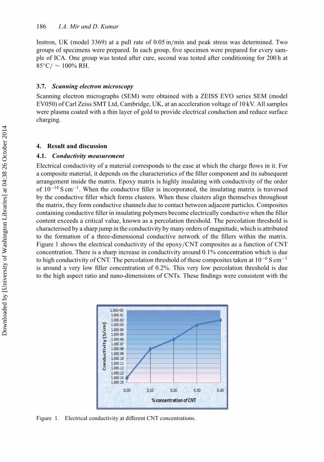
4. Result and discussion4.1. Conductivity measurementElectrical conductivity of a material corresponds to the ease at which the charge flows in it. Fora composite material, it depends on the characteristics of the filler component and its subsequentarrangement inside the matrix. Epoxy matrix is highly insulating with conductivity of the orderof 10−14 S cm−1. When the conductive filler is incorporated, the insulating matrix is traversedby the conductive filler which forms clusters. When these clusters align themselves throughoutthe matrix, they form conductive channels due to contact between adjacent particles. Compositescontaining conductive filler in insulating polymers become electrically conductive when the fillercontent exceeds a critical value, known as a percolation threshold. The percolation threshold ischaracterised by a sharp jump in the conductivity by many orders of magnitude, which is attributedto the formation of a three-dimensional conductive network of the fillers within the matrix.Figure 1 shows the electrical conductivity of the epoxy/CNT composites as a function of CNTconcentration. There is a sharp increase in conductivity around 0.1% concentration which is dueto high conductivity of CNT. The percolation threshold of these composites taken at 10−6 S cm−1
is around a very low filler concentration of 0.2%. This very low percolation threshold is dueto the high aspect ratio and nano-dimensions of CNTs. These findings were consistent with the
Figure 1. Electrical conductivity at different CNT concentrations.
Dow
nloa
ded
by [
Uni
vers
ity o
f W
ashi
ngto
n L
ibra
ries
] at
04:
38 2
6 O
ctob
er 2
014
Nanoscience Methods 187
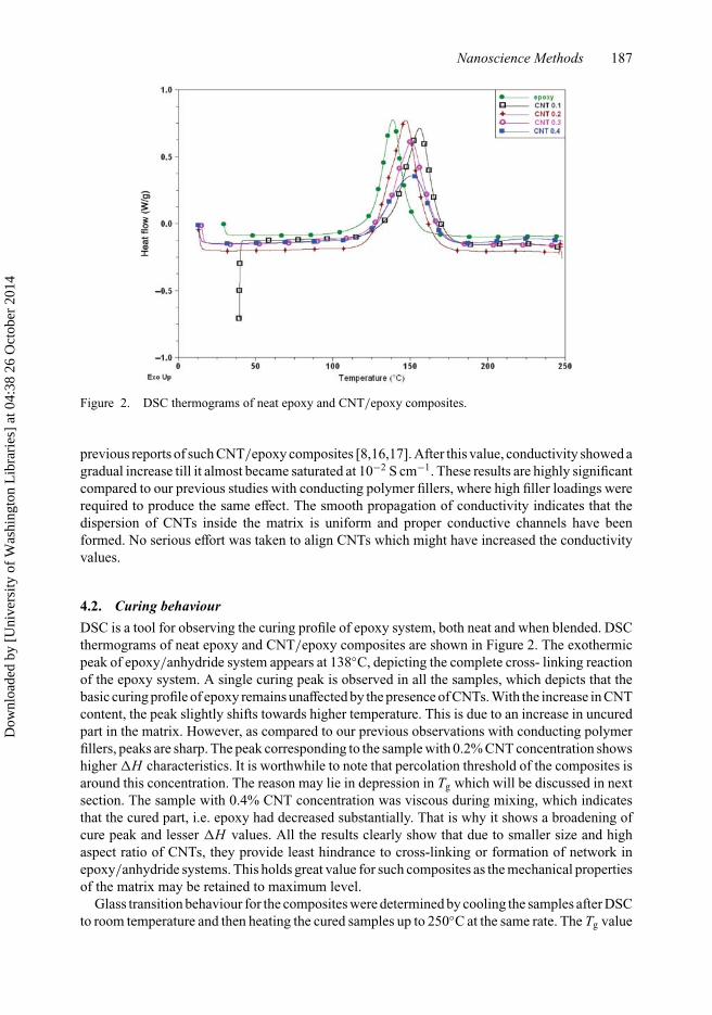
Figure 2. DSC thermograms of neat epoxy and CNT/epoxy composites.
previous reports of such CNT/epoxy composites [8,16,17]. After this value, conductivity showed agradual increase till it almost became saturated at 10−2 S cm−1. These results are highly significantcompared to our previous studies with conducting polymer fillers, where high filler loadings wererequired to produce the same effect. The smooth propagation of conductivity indicates that thedispersion of CNTs inside the matrix is uniform and proper conductive channels have beenformed. No serious effort was taken to align CNTs which might have increased the conductivityvalues.
4.2. Curing behaviourDSC is a tool for observing the curing profile of epoxy system, both neat and when blended. DSCthermograms of neat epoxy and CNT/epoxy composites are shown in Figure 2. The exothermicpeak of epoxy/anhydride system appears at 138◦C, depicting the complete cross- linking reactionof the epoxy system. A single curing peak is observed in all the samples, which depicts that thebasic curing profile of epoxy remains unaffected by the presence of CNTs. With the increase in CNTcontent, the peak slightly shifts towards higher temperature. This is due to an increase in uncuredpart in the matrix. However, as compared to our previous observations with conducting polymerfillers, peaks are sharp. The peak corresponding to the sample with 0.2% CNT concentration showshigher �H characteristics. It is worthwhile to note that percolation threshold of the composites isaround this concentration. The reason may lie in depression in Tg which will be discussed in nextsection. The sample with 0.4% CNT concentration was viscous during mixing, which indicatesthat the cured part, i.e. epoxy had decreased substantially. That is why it shows a broadening ofcure peak and lesser ΔH values. All the results clearly show that due to smaller size and highaspect ratio of CNTs, they provide least hindrance to cross-linking or formation of network inepoxy/anhydride systems. This holds great value for such composites as the mechanical propertiesof the matrix may be retained to maximum level.
Glass transition behaviour for the composites were determined by cooling the samples after DSCto room temperature and then heating the cured samples up to 250◦C at the same rate. The Tg value
Dow
nloa
ded
by [
Uni
vers
ity o
f W
ashi
ngto
n L
ibra
ries
] at
04:
38 2
6 O
ctob
er 2
014

188 I.A. Mir and D. Kumar
Figure 3. Variation of glass transition temperature versus CNT concentration.
of neat epoxy system was found to be around 115◦C. The CNT content dependence of the Tg ispresented in Figure 3. It can be observed that Tg values are affected in almost all samples, however,sample with 0.2% CNT concentration shows an unexpected behaviour. There is a sharp depressionof Tg corresponding to this concentration. This behaviour was confirmed with repeated scans andseems to be independent of epoxy curing. The concentration is around percolation threshold andsuch behaviour has also been observed by Barrau et al. [10]. It is interpreted that conductionpercolation is associated with a particular configuration of the conducting particles in the matrix.At the percolation threshold particles align themselves in definite infinite patterns, while beforethat they exist in finite size clusters. In the percolation range, the free volume accessible to themolecular motion of epoxy chain segments is maximal.
4.3. Thermogravimetric analysisThe weight loss versus temperature curve in Figure 4 shows that the overall degradation char-acteristics of the epoxy system are retained. There is a characteristic two-step transition. Neatepoxy shows a small weight loss before 150◦C which may be due to loss of volatiles and thenundergoes a complete degradation around 600◦C. It is observed that the concentrations from 0.1%to 0.3% show little variation in weight loss characteristics, while beyond that weight loss around150◦C increases. The increase in weight loss may be due to loss of volatiles or some embeddedmoisture. Hence, it is concluded from the results obtained that CNT incorporation does not havea significant effect on the thermal degradation of epoxy systems.
4.4. Environmental ageingResistance to moisture present in the service environment is an important property of ICAs.Moisture may decrease their adhesive property or cause corrosion to metallic component joints.CNT/epoxy composite samples were subjected to 80◦C/ ∼ 100% RH ageing and the effect
Dow
nloa
ded
by [
Uni
vers
ity o
f W
ashi
ngto
n L
ibra
ries
] at
04:
38 2
6 O
ctob
er 2
014
Nanoscience Methods 189
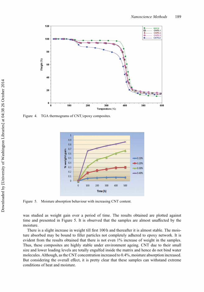
Figure 4. TGA thermograms of CNT/epoxy composites.
Figure 5. Moisture absorption behaviour with increasing CNT content.
was studied as weight gain over a period of time. The results obtained are plotted againsttime and presented in Figure 5. It is observed that the samples are almost unaffected by themoisture.
There is a slight increase in weight till first 100 h and thereafter it is almost stable. The mois-ture absorbed may be bound to filler particles not completely adhered to epoxy network. It isevident from the results obtained that there is not even 1% increase of weight in the samples.Thus, these composites are highly stable under environment ageing. CNT due to their smallsize and lower loading levels are totally engulfed inside the matrix and hence do not bind watermolecules. Although, as the CNT concentration increased to 0.4%, moisture absorption increased.But considering the overall effect, it is pretty clear that these samples can withstand extremeconditions of heat and moisture.
Dow
nloa
ded
by [
Uni
vers
ity o
f W
ashi
ngto
n L
ibra
ries
] at
04:
38 2
6 O
ctob
er 2
014
190 I.A. Mir and D. Kumar
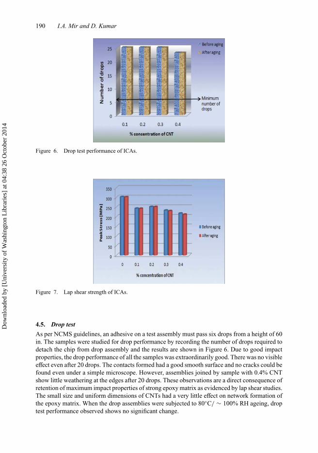
Figure 6. Drop test performance of ICAs.
Figure 7. Lap shear strength of ICAs.
4.5. Drop testAs per NCMS guidelines, an adhesive on a test assembly must pass six drops from a height of 60in. The samples were studied for drop performance by recording the number of drops required todetach the chip from drop assembly and the results are shown in Figure 6. Due to good impactproperties, the drop performance of all the samples was extraordinarily good. There was no visibleeffect even after 20 drops. The contacts formed had a good smooth surface and no cracks could befound even under a simple microscope. However, assemblies joined by sample with 0.4% CNTshow little weathering at the edges after 20 drops. These observations are a direct consequence ofretention of maximum impact properties of strong epoxy matrix as evidenced by lap shear studies.The small size and uniform dimensions of CNTs had a very little effect on network formation ofthe epoxy matrix. When the drop assemblies were subjected to 80◦C/ ∼ 100% RH ageing, droptest performance observed shows no significant change.
Dow
nloa
ded
by [
Uni
vers
ity o
f W
ashi
ngto
n L
ibra
ries
] at
04:
38 2
6 O
ctob
er 2
014
Nanoscience Methods 191
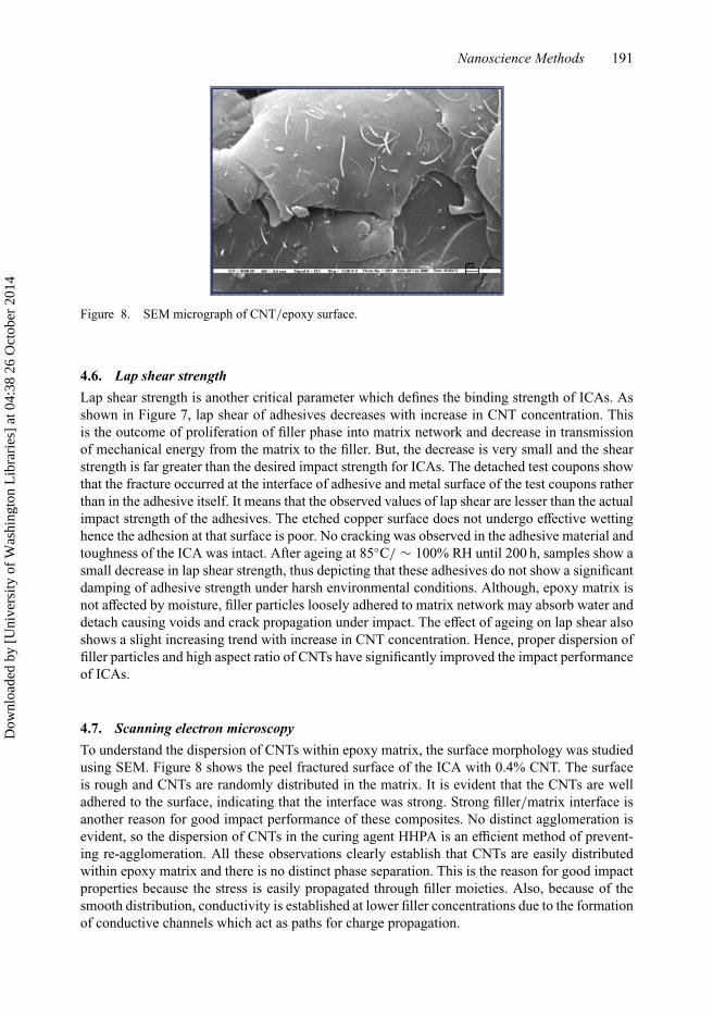
Figure 8. SEM micrograph of CNT/epoxy surface.
4.6. Lap shear strengthLap shear strength is another critical parameter which defines the binding strength of ICAs. Asshown in Figure 7, lap shear of adhesives decreases with increase in CNT concentration. Thisis the outcome of proliferation of filler phase into matrix network and decrease in transmissionof mechanical energy from the matrix to the filler. But, the decrease is very small and the shearstrength is far greater than the desired impact strength for ICAs. The detached test coupons showthat the fracture occurred at the interface of adhesive and metal surface of the test coupons ratherthan in the adhesive itself. It means that the observed values of lap shear are lesser than the actualimpact strength of the adhesives. The etched copper surface does not undergo effective wettinghence the adhesion at that surface is poor. No cracking was observed in the adhesive material andtoughness of the ICA was intact. After ageing at 85◦C/ ∼ 100% RH until 200 h, samples show asmall decrease in lap shear strength, thus depicting that these adhesives do not show a significantdamping of adhesive strength under harsh environmental conditions. Although, epoxy matrix isnot affected by moisture, filler particles loosely adhered to matrix network may absorb water anddetach causing voids and crack propagation under impact. The effect of ageing on lap shear alsoshows a slight increasing trend with increase in CNT concentration. Hence, proper dispersion offiller particles and high aspect ratio of CNTs have significantly improved the impact performanceof ICAs.
4.7. Scanning electron microscopyTo understand the dispersion of CNTs within epoxy matrix, the surface morphology was studiedusing SEM. Figure 8 shows the peel fractured surface of the ICA with 0.4% CNT. The surfaceis rough and CNTs are randomly distributed in the matrix. It is evident that the CNTs are welladhered to the surface, indicating that the interface was strong. Strong filler/matrix interface isanother reason for good impact performance of these composites. No distinct agglomeration isevident, so the dispersion of CNTs in the curing agent HHPA is an efficient method of prevent-ing re-agglomeration. All these observations clearly establish that CNTs are easily distributedwithin epoxy matrix and there is no distinct phase separation. This is the reason for good impactproperties because the stress is easily propagated through filler moieties. Also, because of thesmooth distribution, conductivity is established at lower filler concentrations due to the formationof conductive channels which act as paths for charge propagation.
Dow
nloa
ded
by [
Uni
vers
ity o
f W
ashi
ngto
n L
ibra
ries
] at
04:
38 2
6 O
ctob
er 2
014
192 I.A. Mir and D. Kumar
5. ConclusionsMWCNTs were used as filler in epoxy/anhydride systems and studied for their applicationas ICAs. This study reveals that small size and uniformity of dimensions play an importantrole in defining the suitability of a material for being used as filler in ICAs. CNTs have highimpact strength and good aspect ratio; hence, a higher percentage of the epoxy shear strength isretained. Conductivity is established at a very low filler loading and conductivity value as highas 10−2 S cm−1 was obtained at a filler concentration of only 0.3%. The ICAs so formed notonly show good adhesion but also show least effect of ageing. The surface characteristics showthat there is a strong interface between matrix and filler phases, which defines the worth of anefficient composite system. Hence, it is concluded that incorporation of CNTs as filler insidethe epoxy matrix produces ICAs with high electrical conductivity, great impact strength at verylow filler loadings. The overall properties of these samples establish their use as ICAs for elec-tronic interconnections. However, the properties may further be improved by devising methodsfor incorporating higher concentrations of CNTs through more efficient dispersion agents. Also,introducing functionalisation may improve adhesion and thus increase the impact performancefurther.
AcknowledgementsThe authors express their sincere gratitude to the vice chancellor, Delhi Technological University, Delhi,for his kind encouragement and support. One of the authors, Irfan Ahmad Mir, is thankful to the Council ofScientific and Industrial Research, Government of India, for providing financial support as senior researchfellowship.
References
[1] I. Mir and D. Kumar, Recent advances in isotropic conductive adhesives for electronics packaging applications, Int.J. Adhes. Adhes. 28 (2008), pp. 362–371.
[2] I.A. Mir and D. Kumar, Development of polyaniline/epoxy composite as a prospective solder replacement material,Int. J. Polym. Mater. 59 (2010), pp. 994–1007.
[3] I.A. Mir and D. Kumar, Development of polypyrrole/epoxy composites as isotropically conductive adhesives, J.Adhes. 86 (2010), pp. 447–462.
[4] A. Allaoui, S. Bai, H.M. Cheng, and J.B. Bai, Mechanical and electrical properties of a MWNT/epoxy composite,Compos. Sci. Technol. 62 (2002), pp. 1993–1998.
[5] X. Xu, M.M. Thwe, C. Shearwood, and K. Liao, Mechanical properties and interfacial characteristics of carbon-nanotube-reinforced epoxy thin films, Appl. Phys. Lett. 81 (2002), pp. 2833–2835.
[6] D. Puglia, L. Valentini, and J.M. Kenny, Analysis of the cure reaction of carbon nanotubes/epoxy resin compositesthrough thermal analysis and Raman spectroscopy, J. Appl. Polym. Sci. 88 (2003), pp. 452–458.
[7] P.M. Ajayan, O. Stephan, C. Colliex, and D. Trauth, Aligned carbon nanotube arrays formed by cutting a polymerresin-nanotube composite, Science 265 (1994), pp. 1212–1214.
[8] C.A. Martin, J. Sandler, A.H. Windle, M. Schwarz, W. Bauhofer, and K. Schulte, Electric field-induced alignedmulti-wall carbon nanotube networks in epoxy composites, Polymer 46 (2005), pp. 877–886.
[9] F.H. Gojny, M. Wichmann, U. Kopke, B. Fiedler, and K. Schulte, Carbon nanotube-reinforced epoxy-composites: Enhanced stiffness and fracture toughness at low nanotube content, Compos. Sci. Technol. 64 (2004),pp. 2363–2371.
[10] S. Barrau, P. Demont, C. Maraval, A. Bernes, and C. Lacabanne, Glass transition temperature depression at thepercolation threshold in carbon nanotube-epoxy resin and polypyrrole-epoxy resin composites, Macromol. RapidCommun. 26 (2005), pp. 390–394.
[11] Y. Zhou, F. Pervin, L. Lewis, and S. Jeelani, Fabrication and characterization of carbon/epoxy composites mixedwith multi-walled carbon nanotubes, Mater. Sci. Eng. A 475 (2008), pp. 157–165.
[12] J. Li and J.K. Lumpp, Carbon nanotube filled conductive adhesives for aerospace applications, Proceedings of theAerospace Conference, IEEE, Big Sky, MT, USA, 2007, pp. 1–6.
[13] Q.F. Cheng, J.P. Wang, J.J. Wen, C.H. Liu, K.L. Jiang, and Q.Q. Li, Carbon nanotube/epoxy composites fabricatedby resin transfer molding, Carbon 48 (2010), pp. 260–266.
[14] Y. Rao, D. Lu, and C.P. Wong, A study of impact performance of conductive adhesives, Int. J. Adhes. Adhes. 24(2004), pp. 449–453.
Dow
nloa
ded
by [
Uni
vers
ity o
f W
ashi
ngto
n L
ibra
ries
] at
04:
38 2
6 O
ctob
er 2
014
Nanoscience Methods 193
[15] S. Xu, DA. Dillard, and J.G. Dillard, Environmental aging effects on the durability of electrically conductive adhesivejoints, Int. J. Adhes. Adhes. 23 (2003), pp. 235–250.
[16] J.K.W. Sandler, J.E. Kirk, I.A. Kinloch, M.S.P. Shaffer, and A.H. Windle, Ultra-low electrical percolation thresholdin carbon-nanotube-epoxy composites, Polymer 44 (2003), pp. 5893–5899.
[17] A. Moisala, Q. Li, I.A. Kinloch, and A.H. Windle, Thermal and electrical conductivity of single- and multi-walledcarbon nanotube-epoxy composites, Compos. Sci. Technol. 66 (2006), pp. 1285-1288.
Dow
nloa
ded
by [
Uni
vers
ity o
f W
ashi
ngto
n L
ibra
ries
] at
04:
38 2
6 O
ctob
er 2
014