Embed Size (px)
Citation preview
CO Guardian LLC Document # 454-201
1951 E. AIRPORT DRIVE Date: 10/28/11
TUCSON, AZ. 85706 REV D.
454 MODEL OWNERS/INSTALLATION MANUAL Page 1 of 25
OWNERS MANUAL
OPERATION AND INSTALLATION
PROCEDURE AND LIMITATIONS
CARBON MONOXIDE DETECTOR
MODEL AERO 454-201
REMOTE UNIT
Rev. D

CO Guardian LLC Document # 454-201
1951 E. AIRPORT DRIVE Date: 10/28/11
TUCSON, AZ. 85706 REV D.
454 MODEL OWNERS/INSTALLATION MANUAL Page 2 of 25
LOG OF REVISIONS
REV
NO.
PAGE
NO.
DATE
DESCRIPTION
APPROVED
A
1 thru 22
05/11/11
Initial Release
ASH VIJ
B 1 thru 22
10/17/11 Bluetooth paring
indications
ASH VIJ
C 1 thru 23
10/26/11 Revised document ASH VIJ
D 1 thru 23 10/28/11 Updated leading
particulars
ASH VIJ
CO Guardian LLC Document # 454-201
1951 E. AIRPORT DRIVE Date: 10/28/11
TUCSON, AZ. 85706 REV D.
454 MODEL OWNERS/INSTALLATION MANUAL Page 3 of 25
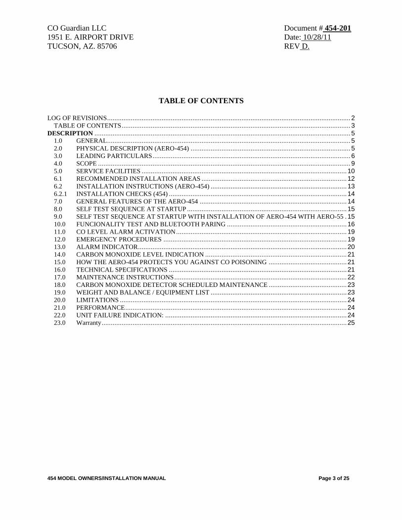
TABLE OF CONTENTS
LOG OF REVISIONS ...................................................................................................................................... 2
TABLE OF CONTENTS .............................................................................................................................. 3 DESCRIPTION ............................................................................................................................................. 5
1.0 GENERAL ...................................................................................................................................... 5 2.0 PHYSICAL DESCRIPTION (AERO-454) ........................................................................................ 5 3.0 LEADING PARTICULARS ............................................................................................................. 6 4.0 SCOPE ........................................................................................................................................... 9 5.0 SERVICE FACILITIES ................................................................................................................. 10 6.1 RECOMMENDED INSTALLATION AREAS ................................................................................ 12 6.2 INSTALLATION INSTRUCTIONS (AERO-454) ........................................................................... 13 6.2.1 INSTALLATION CHECKS (454) .................................................................................................. 14 7.0 GENERAL FEATURES OF THE AERO-454 ................................................................................. 14 8.0 SELF TEST SEQUENCE AT STARTUP ........................................................................................ 15 9.0 SELF TEST SEQUENCE AT STARTUP WITH INSTALLATION OF AERO-454 WITH AERO-55 . 15 10.0 FUNCIONALITY TEST AND BLUETOOTH PARING .................................................................. 16 11.0 CO LEVEL ALARM ACTIVATION .............................................................................................. 19 12.0 EMERGENCY PROCEDURES ..................................................................................................... 19 13.0 ALARM INDICATOR ................................................................................................................... 20 14.0 CARBON MONOXIDE LEVEL INDICATION .............................................................................. 21 15.0 HOW THE AERO-454 PROTECTS YOU AGAINST CO POISONING ........................................... 21 16.0 TECHNICAL SPECIFICATIONS .................................................................................................. 21 17.0 MAINTENANCE INSTRUCTIONS ............................................................................................... 22 18.0 CARBON MONOXIDE DETECTOR SCHEDULED MAINTENANCE ........................................... 23 19.0 WEIGHT AND BALANCE / EQUIPMENT LIST ........................................................................... 23 20.0 LIMITATIONS ............................................................................................................................. 24 21.0 PERFORMANCE .......................................................................................................................... 24 22.0 UNIT FAILURE INDICATION: .................................................................................................... 24 23.0 Warranty ....................................................................................................................................... 25
CO Guardian LLC Document # 454-201
1951 E. AIRPORT DRIVE Date: 10/28/11
TUCSON, AZ. 85706 REV D.
454 MODEL OWNERS/INSTALLATION MANUAL Page 4 of 25
FORWARD
This document provides information intended for use by persons who, pursuant to current
requirements, are qualified to install this equipment. Because equipment and system installations
vary depending on a particular aircraft, this document is intended only as a guideline. If further
information is required, contact:
CO Guardian, LLC
1951 E. Airport Drive
Tucson, AZ 85706
(520) 889-1177
(800) 639-7139
www.coguardian.com
We welcome your comments concerning this document. Although every effort has been made to
keep it free of errors, some may occur. When reporting a specific problem, please describe it
briefly and include the document number, the paragraph/figure/picture/table number, and the
page number. Send your comments to the address above.
CO Guardian LLC Document # 454-201
1951 E. AIRPORT DRIVE Date: 10/28/11
TUCSON, AZ. 85706 REV D.
454 MODEL OWNERS/INSTALLATION MANUAL Page 5 of 25
DESCRIPTION
1.0 GENERAL
This section gives a physical and functional description of the CO Guardian CO Detector
unit (AERO 454-201) as installed in a typical reciprocating engine type aircraft. See
physical description below.
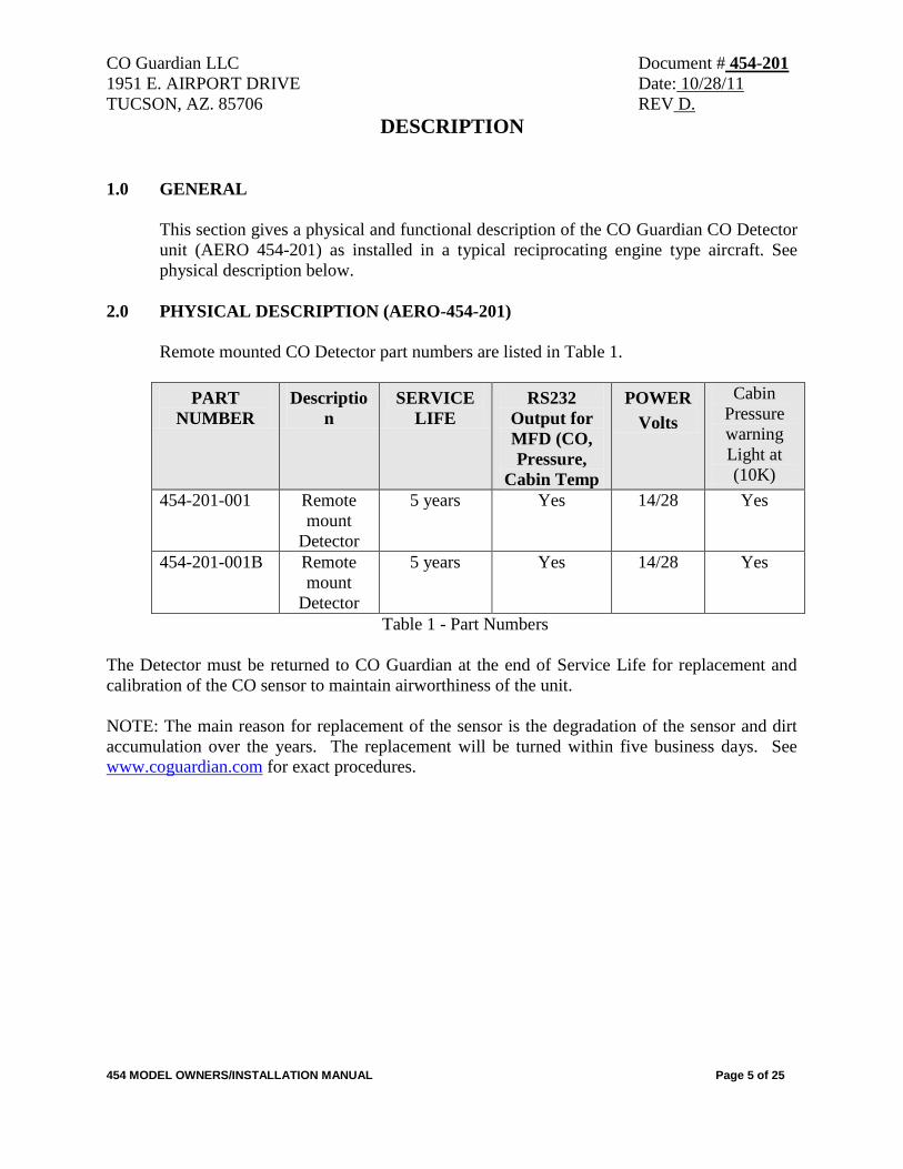
2.0 PHYSICAL DESCRIPTION (AERO-454-201)
Remote mounted CO Detector part numbers are listed in Table 1.
PART
NUMBER
Descriptio
n
SERVICE
LIFE
RS232
Output for
MFD (CO,
Pressure,
Cabin Temp
POWER
Volts
Cabin
Pressure
warning
Light at
(10K)
454-201-001 Remote
mount
Detector
5 years Yes 14/28 Yes
454-201-001B Remote
mount
Detector
5 years Yes 14/28 Yes
Table 1 - Part Numbers
The Detector must be returned to CO Guardian at the end of Service Life for replacement and
calibration of the CO sensor to maintain airworthiness of the unit.
NOTE: The main reason for replacement of the sensor is the degradation of the sensor and dirt
accumulation over the years. The replacement will be turned within five business days. See
www.coguardian.com for exact procedures.
CO Guardian LLC Document # 454-201
1951 E. AIRPORT DRIVE Date: 10/28/11
TUCSON, AZ. 85706 REV D.
454 MODEL OWNERS/INSTALLATION MANUAL Page 6 of 25
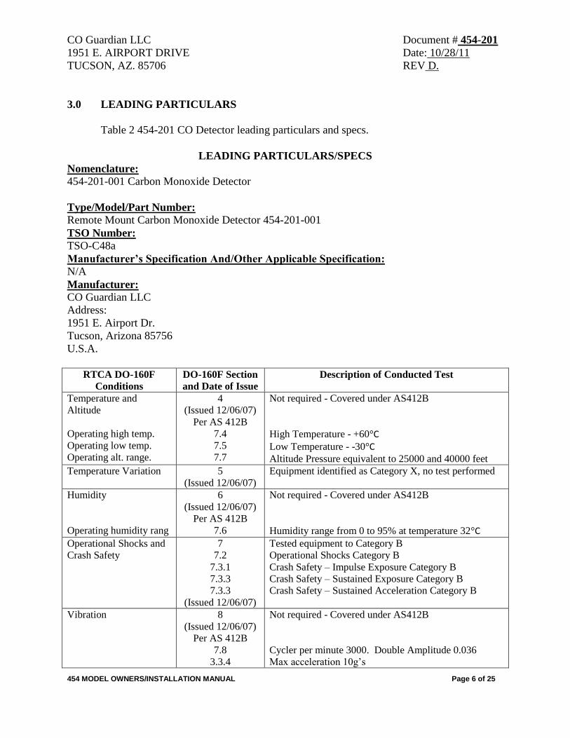
3.0 LEADING PARTICULARS
Table 2 454-201 CO Detector leading particulars and specs.
LEADING PARTICULARS/SPECS
Nomenclature:
454-201-001 Carbon Monoxide Detector
Type/Model/Part Number:
Remote Mount Carbon Monoxide Detector 454-201-001
TSO Number:
TSO-C48a
Manufacturer’s Specification And/Other Applicable Specification:
N/A
Manufacturer:
CO Guardian LLC
Address:
1951 E. Airport Dr.
Tucson, Arizona 85756
U.S.A.
RTCA DO-160F
Conditions
DO-160F Section
and Date of Issue
Description of Conducted Test
Temperature and
Altitude
Operating high temp.
Operating low temp.
Operating alt. range.
4
(Issued 12/06/07)
Per AS 412B
7.4
7.5
7.7
Not required - Covered under AS412B
High Temperature - +60°C Low Temperature - -30°C
Altitude Pressure equivalent to 25000 and 40000 feet
Temperature Variation 5
(Issued 12/06/07)
Equipment identified as Category X, no test performed
Humidity
Operating humidity rang
6
(Issued 12/06/07)
Per AS 412B
7.6
Not required - Covered under AS412B
Humidity range from 0 to 95% at temperature 32°C
Operational Shocks and
Crash Safety
7
7.2
7.3.1
7.3.3
7.3.3
(Issued 12/06/07)
Tested equipment to Category B
Operational Shocks Category B
Crash Safety – Impulse Exposure Category B
Crash Safety – Sustained Exposure Category B
Crash Safety – Sustained Acceleration Category B
Vibration 8
(Issued 12/06/07)
Per AS 412B
7.8
3.3.4
Not required - Covered under AS412B
Cycler per minute 3000. Double Amplitude 0.036
Max acceleration 10g’s
CO Guardian LLC Document # 454-201
1951 E. AIRPORT DRIVE Date: 10/28/11
TUCSON, AZ. 85706 REV D.
454 MODEL OWNERS/INSTALLATION MANUAL Page 7 of 25
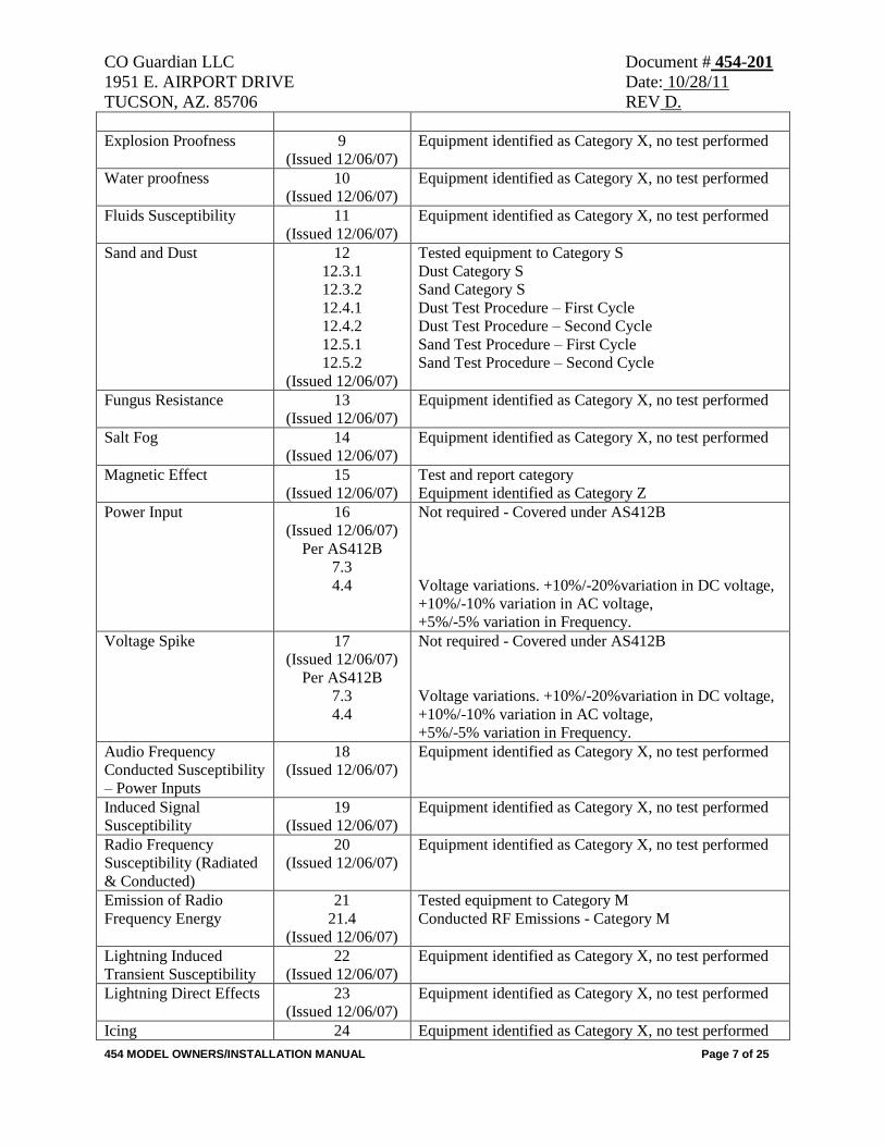
Explosion Proofness 9
(Issued 12/06/07)
Equipment identified as Category X, no test performed
Water proofness 10
(Issued 12/06/07)
Equipment identified as Category X, no test performed
Fluids Susceptibility 11
(Issued 12/06/07)
Equipment identified as Category X, no test performed
Sand and Dust 12
12.3.1
12.3.2
12.4.1
12.4.2
12.5.1
12.5.2
(Issued 12/06/07)
Tested equipment to Category S
Dust Category S
Sand Category S
Dust Test Procedure – First Cycle
Dust Test Procedure – Second Cycle
Sand Test Procedure – First Cycle
Sand Test Procedure – Second Cycle
Fungus Resistance 13
(Issued 12/06/07)
Equipment identified as Category X, no test performed
Salt Fog 14
(Issued 12/06/07)
Equipment identified as Category X, no test performed
Magnetic Effect 15
(Issued 12/06/07)
Test and report category
Equipment identified as Category Z
Power Input 16
(Issued 12/06/07)
Per AS412B
7.3
4.4
Not required - Covered under AS412B
Voltage variations. +10%/-20%variation in DC voltage,
+10%/-10% variation in AC voltage,
+5%/-5% variation in Frequency.
Voltage Spike 17
(Issued 12/06/07)
Per AS412B
7.3
4.4
Not required - Covered under AS412B
Voltage variations. +10%/-20%variation in DC voltage,
+10%/-10% variation in AC voltage,
+5%/-5% variation in Frequency.
Audio Frequency
Conducted Susceptibility
– Power Inputs
18
(Issued 12/06/07)
Equipment identified as Category X, no test performed
Induced Signal
Susceptibility
19
(Issued 12/06/07)
Equipment identified as Category X, no test performed
Radio Frequency
Susceptibility (Radiated
& Conducted)
20
(Issued 12/06/07)
Equipment identified as Category X, no test performed
Emission of Radio
Frequency Energy
21
21.4
(Issued 12/06/07)
Tested equipment to Category M
Conducted RF Emissions - Category M
Lightning Induced
Transient Susceptibility
22
(Issued 12/06/07)
Equipment identified as Category X, no test performed
Lightning Direct Effects 23
(Issued 12/06/07)
Equipment identified as Category X, no test performed
Icing 24 Equipment identified as Category X, no test performed
CO Guardian LLC Document # 454-201
1951 E. AIRPORT DRIVE Date: 10/28/11
TUCSON, AZ. 85706 REV D.
454 MODEL OWNERS/INSTALLATION MANUAL Page 8 of 25
(Issued 12/06/07)
Electrostatic Discharge 25
(Issued 12/06/07)
Equipment identified as Category X, no test performed
Fire, Flammability 26
(Issued 12/06/07)
Equipment identified as Category X, no test performed
Table 2 Leading Particulars
CO Guardian LLC Document # 454-201
1951 E. AIRPORT DRIVE Date: 10/28/11
TUCSON, AZ. 85706 REV D.
454 MODEL OWNERS/INSTALLATION MANUAL Page 9 of 25
4.0 SCOPE
The Model 454-201-001 Carbon Monoxide Detector is designed to be installed along
with the AERO 455-101-003 unit to detect, measure, and provide a visual alert to the
crew of Reciprocating Engine type aircraft before the cockpit level of carbon monoxide
(CO) reaches a critical level, and enables the occupants of the aircraft to monitor their
physiological condition using a pulse oximeter (455-101-003) installed in the cockpit’s
instrument panel measuring SPO2 (oxygen saturation percentage in blood) and hearth
rate.
Model 454-201-001B is a stand alone unit with the option of adding a Bluetooth Pulse
Oximeter device (AERO 901).
The installation consists of a single remote mounted CO Detector instrument operating on
aircraft DC power (14v or 28v). The aircraft supplied power and aircraft wiring is
protected by a 2 ampere, resettable, trip free, type circuit breaker. The pulse oximeter
(AERO 455-101-003) recommended installation location is on the aircraft’s instrument
panel where it can be reached by both pilot and copilot at all times.
The CO Detector installation consists of the AERO-454 unit remotely mounted behind
the cockpit instrument panel, or anywhere else where there is room for it.
The carbon monoxide alarm level is calibrated to provide a visual alert on the aircraft’s
MFD within 5 minutes or less whenever the carbon monoxide level reaches 50 parts per
million (PPM) by volume or greater. The warning time is shortened at higher levels of
CO concentrations and becomes approximately instant should the carbon monoxide level
reach 400 parts per million by volume (PPM) or greater.
In case of a carbon monoxide alert, the pilot will receive a visual warning alert displayed
on the aircraft’s MFD, or on the AERO 55-101-003 display unit if installed. The visual
alert will remain until the carbon monoxide level is reduced below the alert level. The
indicator is automatically reset when the CO level drops below 50 PPM. There is a three-
minute delay at startup to stabilize the sensor before the unit will accurately sense CO
levels.
The 454 have a built in pressure compensation sensor to detect cabin altitude changes up
to 25,000 to give a better accuracy in CO detection. This model also alarms if the cabin
altitude goes above 10,000 feet. This model also has RS232 output for display data of CO
Level on Garmin GNS480, G1000 and other manufacturers. See website
www.coguardian.com to see the latest manufacturers capable of showing data on Multi
Function Displays.
CO Guardian LLC Document # 454-201
1951 E. AIRPORT DRIVE Date: 10/28/11
TUCSON, AZ. 85706 REV D.
454 MODEL OWNERS/INSTALLATION MANUAL Page 10 of 25
5.0 SERVICE FACILITIES
The operator can service all other components of the installation at an FAA certified
Repair Station or by A&P mechanic. CO Detectors must be returned to CO Guardian for
repair, calibration or overhaul. The sensor life is 5 years from date of installation.
NOTE
The sensor requires special gases for testing. If any discrepancies are found with
the unit during installation or during the operational service life, the unit must be
returned to CO Guardian for repair or replacement. The CO Detector unit must be
returned to the manufacturer for CO sensor replacement and re-calibration at the
end of the service life applicable to the unit’s part number.
6.0 INSTALLATION 454
The following documents the installation criteria of the AERO-454 Carbon Monoxide
detector.
a. Choose a location behind the instrument panel for the installation of the CO Detector.
Choose a location with space available that also meets the following criteria. The unit can
be installed on any side behind the instrument panel.
b. Insure that the area around the CO Detector panel location will permit unrestricted
airflow through the unit.
c. Install in an area not exposed to excessively dusty or dirty conditions.
d. Insure that the air intake on the front of the CO Detector is not obstructed in any manner.
e. Install the CO Detector in a location without high or disturbed airflow movement. The
CO Detector will detect the presence of CO more effectively if the unit does not have air
blowing over it.
f. Insure that the CO Detector installation area meets the temperature and humidity ranges
listed in the List of Particulars specifications. Temperature and humidity conditions
outside the specification may affect the sensitivity of the detector.
CO Guardian LLC Document # 454-201
1951 E. AIRPORT DRIVE Date: 10/28/11
TUCSON, AZ. 85706 REV D.
454 MODEL OWNERS/INSTALLATION MANUAL Page 11 of 25
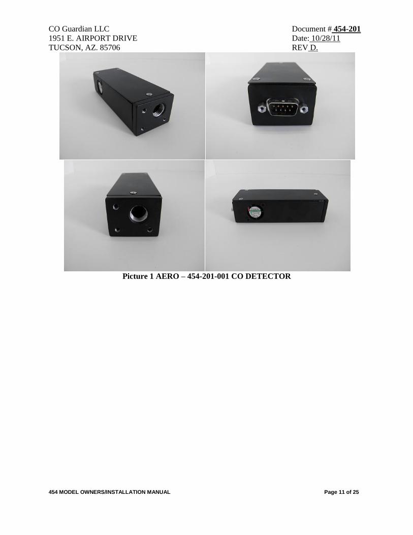
Picture 1 AERO – 454-201-001 CO DETECTOR
CO Guardian LLC Document # 454-201
1951 E. AIRPORT DRIVE Date: 10/28/11
TUCSON, AZ. 85706 REV D.
454 MODEL OWNERS/INSTALLATION MANUAL Page 12 of 25
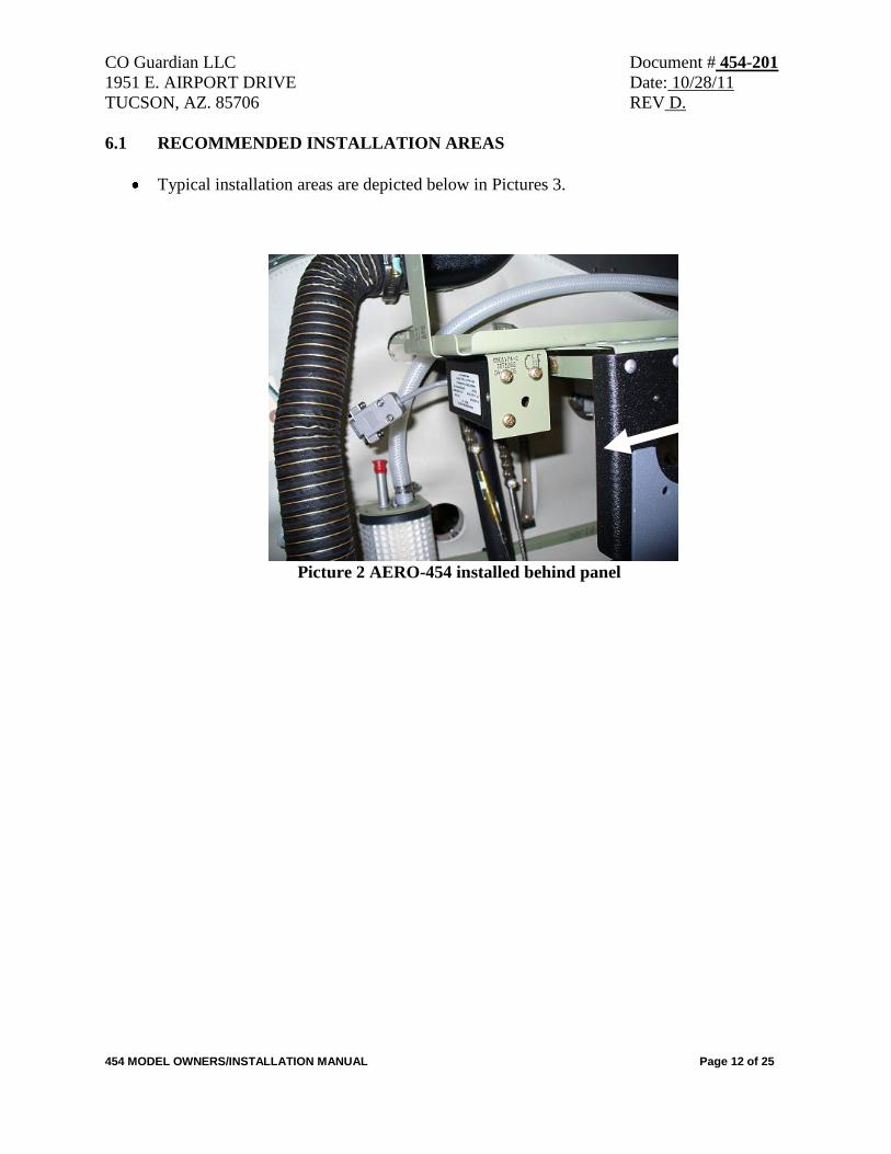
6.1 RECOMMENDED INSTALLATION AREAS
Typical installation areas are depicted below in Pictures 3.
Picture 2 AERO-454 installed behind panel
CO Guardian LLC Document # 454-201
1951 E. AIRPORT DRIVE Date: 10/28/11
TUCSON, AZ. 85706 REV D.
454 MODEL OWNERS/INSTALLATION MANUAL Page 13 of 25
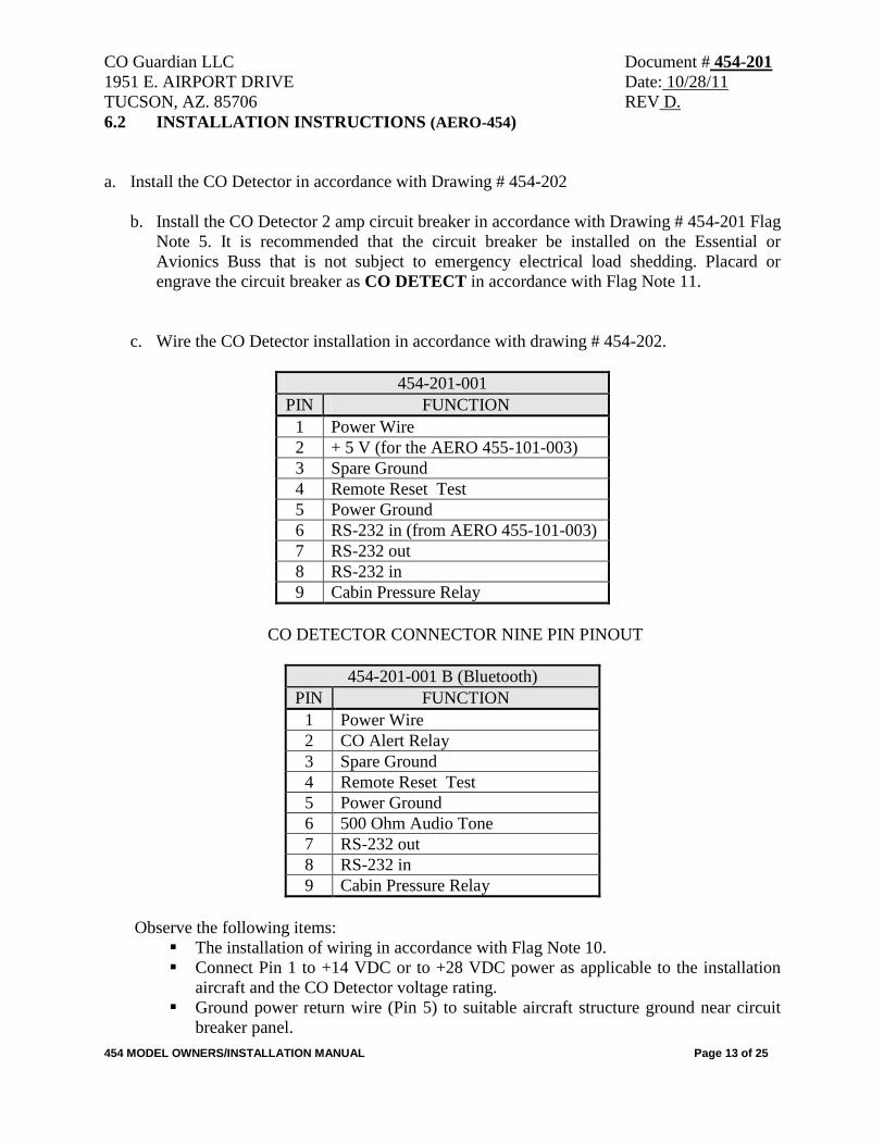
6.2 INSTALLATION INSTRUCTIONS (AERO-454)
a. Install the CO Detector in accordance with Drawing # 454-202
b. Install the CO Detector 2 amp circuit breaker in accordance with Drawing # 454-201 Flag
Note 5. It is recommended that the circuit breaker be installed on the Essential or
Avionics Buss that is not subject to emergency electrical load shedding. Placard or
engrave the circuit breaker as CO DETECT in accordance with Flag Note 11.
c. Wire the CO Detector installation in accordance with drawing # 454-202.
454-201-001
PIN FUNCTION
1 Power Wire
2 + 5 V (for the AERO 455-101-003)
3 Spare Ground
4 Remote Reset Test
5 Power Ground
6 RS-232 in (from AERO 455-101-003)
7 RS-232 out
8 RS-232 in
9 Cabin Pressure Relay
CO DETECTOR CONNECTOR NINE PIN PINOUT
454-201-001 B (Bluetooth)
PIN FUNCTION
1 Power Wire
2 CO Alert Relay
3 Spare Ground
4 Remote Reset Test
5 Power Ground
6 500 Ohm Audio Tone
7 RS-232 out
8 RS-232 in
9 Cabin Pressure Relay
Observe the following items:
The installation of wiring in accordance with Flag Note 10.
Connect Pin 1 to +14 VDC or to +28 VDC power as applicable to the installation
aircraft and the CO Detector voltage rating.
Ground power return wire (Pin 5) to suitable aircraft structure ground near circuit
breaker panel.
CO Guardian LLC Document # 454-201
1951 E. AIRPORT DRIVE Date: 10/28/11
TUCSON, AZ. 85706 REV D.
454 MODEL OWNERS/INSTALLATION MANUAL Page 14 of 25
6.2.1 INSTALLATION CHECKS (454)
a. With the CO Detector disconnected from the aircraft harness, conduct a continuity check
of the added aircraft wiring.
b. Turn ON the aircraft Battery Switch. Close the CO DETECT circuit breaker and measure
aircraft voltage between pins 1 and 5 of the CO Detector connector. Pull the CO
DETECT circuit breaker. Verify the voltage between pins 1 and 5 is OFF.
c. Close the CO DETECT KEEP ALIVE circuit breaker and measure aircraft voltage
between pins 9 and 5 of the CO Detector connector. Turn aircraft Battery switch OFF.
Measure aircraft voltage between pins 9 and 5 of the CO Detector connector. Pull the
CO DETECT KEEP ALIVE circuit breaker. Verify the voltage between pins 9 and 5 is
OFF.
d. Connect the CO Detector connector to the aircraft harness. Turn aircraft Battery Switch
ON. Close CO DETECT circuit breaker.
e. Verify the unit can be shut off with the CO DETECT circuit breaker.
a. Determine the moment arm for the installed CO Detector location and record in aircraft
weight and balance manual. CO Detector weight is 4 oz.
7.0 GENERAL FEATURES OF THE AERO-454
- CO detector from 10 – 999 PPM
- Cabin Temperature
- Cabin Pressure
- Reminder to check SPO2 periodically based on cabin altitude (When 455-101-003 or
AERO 901 are installed)
- Tone generator for headsets
- Relay to CO and Cabin pressure
- Inside temperature
CO Guardian LLC Document # 454-201
1951 E. AIRPORT DRIVE Date: 10/28/11
TUCSON, AZ. 85706 REV D.
454 MODEL OWNERS/INSTALLATION MANUAL Page 15 of 25
8.0 SELF TEST SEQUENCE AT STARTUP
When the airplane master battery switch is selected ON, the 454 Detector goes through a
self-test routine. The self-test checks for functionality of critical components such as the
CO sensor, temperature sensor, pressure sensor, and integrity of the system and remote
display will remain off if everything working properly. The RS232 MFD will show no
CO on the CO Detector page.
9.0 SELF TEST SEQUENCE AT STARTUP WITH INSTALLATION OF AERO-454
WITH AERO-55
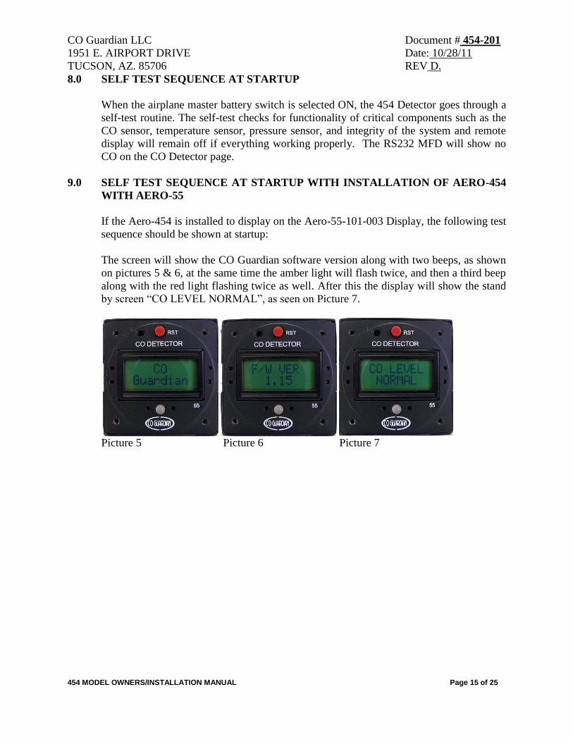
If the Aero-454 is installed to display on the Aero-55-101-003 Display, the following test
sequence should be shown at startup:
The screen will show the CO Guardian software version along with two beeps, as shown
on pictures 5 & 6, at the same time the amber light will flash twice, and then a third beep
along with the red light flashing twice as well. After this the display will show the stand
by screen “CO LEVEL NORMAL”, as seen on Picture 7.
Picture 5 Picture 6 Picture 7
CO Guardian LLC Document # 454-201
1951 E. AIRPORT DRIVE Date: 10/28/11
TUCSON, AZ. 85706 REV D.
454 MODEL OWNERS/INSTALLATION MANUAL Page 16 of 25
10.0 FUNCIONALITY TEST AND BLUETOOTH PARING
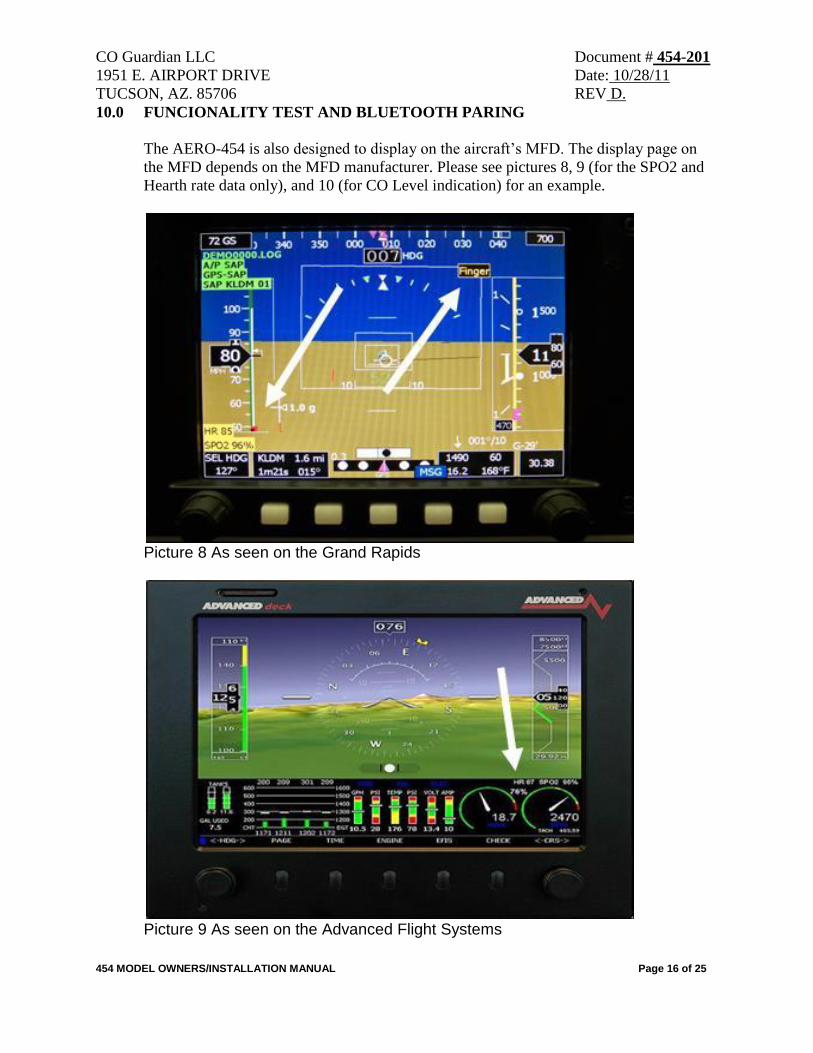
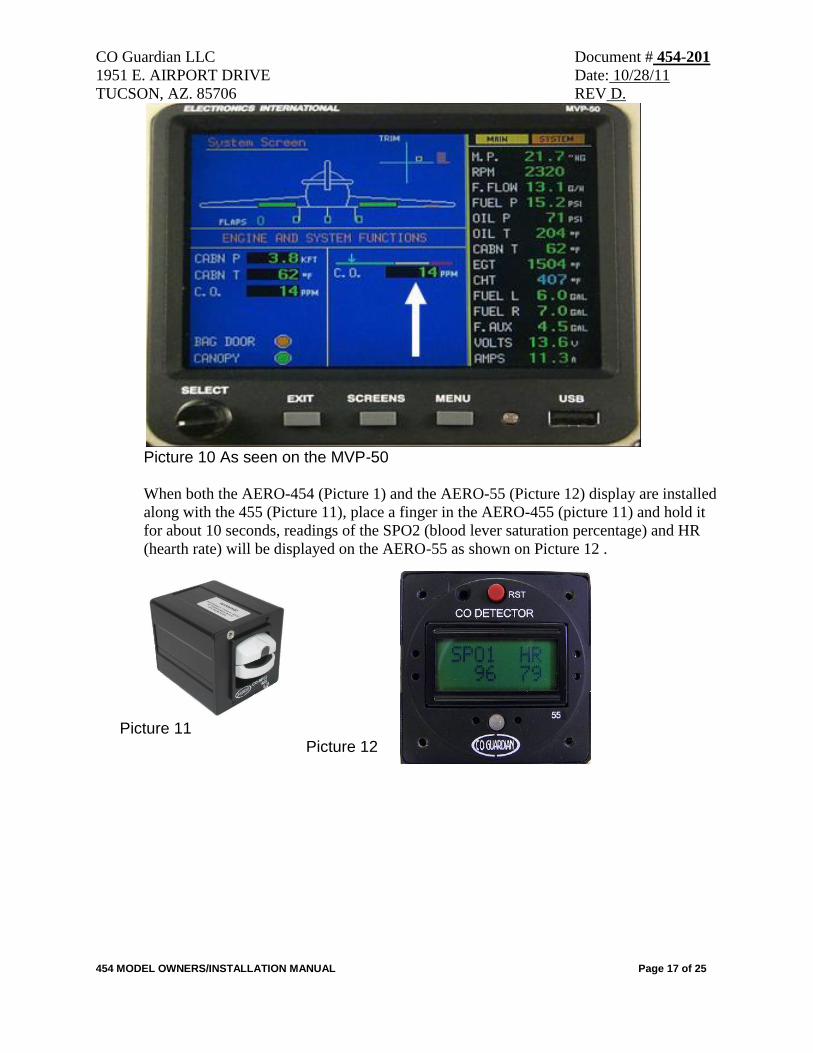
The AERO-454 is also designed to display on the aircraft’s MFD. The display page on
the MFD depends on the MFD manufacturer. Please see pictures 8, 9 (for the SPO2 and
Hearth rate data only), and 10 (for CO Level indication) for an example.
Picture 8 As seen on the Grand Rapids
Picture 9 As seen on the Advanced Flight Systems
CO Guardian LLC Document # 454-201
1951 E. AIRPORT DRIVE Date: 10/28/11
TUCSON, AZ. 85706 REV D.
454 MODEL OWNERS/INSTALLATION MANUAL Page 17 of 25
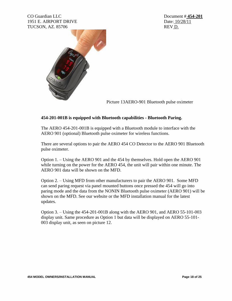
Picture 10 As seen on the MVP-50
When both the AERO-454 (Picture 1) and the AERO-55 (Picture 12) display are installed
along with the 455 (Picture 11), place a finger in the AERO-455 (picture 11) and hold it
for about 10 seconds, readings of the SPO2 (blood lever saturation percentage) and HR
(hearth rate) will be displayed on the AERO-55 as shown on Picture 12 .
Picture 11 Picture 12
CO Guardian LLC Document # 454-201
1951 E. AIRPORT DRIVE Date: 10/28/11
TUCSON, AZ. 85706 REV D.
454 MODEL OWNERS/INSTALLATION MANUAL Page 18 of 25
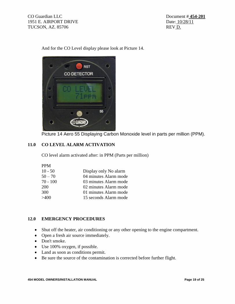
Picture 13AERO-901 Bluetooth pulse oximeter
454-201-001B is equipped with Bluetooth capabilities - Bluetooth Paring.
The AERO 454-201-001B is equipped with a Bluetooth module to interface with the
AERO 901 (optional) Bluetooth pulse oximeter for wireless functions.
There are several options to pair the AERO 454 CO Detector to the AERO 901 Bluetooth
pulse oximeter.
Option 1. – Using the AERO 901 and the 454 by themselves. Hold open the AERO 901
while turning on the power for the AERO 454, the unit will pair within one minute. The
AERO 901 data will be shown on the MFD.
Option 2. – Using MFD from other manufacturers to pair the AERO 901. Some MFD
can send paring request via panel mounted buttons once pressed the 454 will go into
paring mode and the data from the NONIN Bluetooth pulse oximeter (AERO 901) will be
shown on the MFD. See our website or the MFD installation manual for the latest
updates.
Option 3. – Using the 454-201-001B along with the AERO 901, and AERO 55-101-003
display unit. Same procedure as Option 1 but data will be displayed on AERO 55-101-
003 display unit, as seen on picture 12.
CO Guardian LLC Document # 454-201
1951 E. AIRPORT DRIVE Date: 10/28/11
TUCSON, AZ. 85706 REV D.
454 MODEL OWNERS/INSTALLATION MANUAL Page 19 of 25
And for the CO Level display please look at Picture 14.
Picture 14 Aero 55 Displaying Carbon Monoxide level in parts per million (PPM).
11.0 CO LEVEL ALARM ACTIVATION
CO level alarm activated after: in PPM (Parts per million)
PPM
10 - 50 Display only No alarm
50 – 70 04 minutes Alarm mode
70 - 100 03 minutes Alarm mode
200 02 minutes Alarm mode
300 01 minutes Alarm mode
>400 15 seconds Alarm mode
12.0 EMERGENCY PROCEDURES
Shut off the heater, air conditioning or any other opening to the engine compartment.
Open a fresh air source immediately.
Don't smoke.
Use 100% oxygen, if possible.
Land as soon as conditions permit.
Be sure the source of the contamination is corrected before further flight.
CO Guardian LLC Document # 454-201
1951 E. AIRPORT DRIVE Date: 10/28/11
TUCSON, AZ. 85706 REV D.
454 MODEL OWNERS/INSTALLATION MANUAL Page 20 of 25
NOTE: The alert message will stay on until the CO level goes below 50 parts per
million (PPM) by volume of carbon monoxide concentration. SEE MFD manual if
the “ALERT” display is integrated with the Manufacturers MFD.
DO not recycle the unit through the circuit breaker. A three-minute delay is
required for the CO sensor to stabilize after each power-up in the 454 unit.
13.0 ALARM INDICATOR
Relevant alert messages will display on multi-function display like (G1000, GNS480, EI-
50 and others).
The RS-232 Data Buss option is currently available on numerous MFD units. The RS-
232 data buss output will couple CO Detector status information to electronic display
systems with RS-232 input capability.
See Multi-Function display manufacturers Installation Manual for interface guidance.
The CO ALERT can be reset through the RS-232 interface provided the Multi-Function
system contains the reset capability.
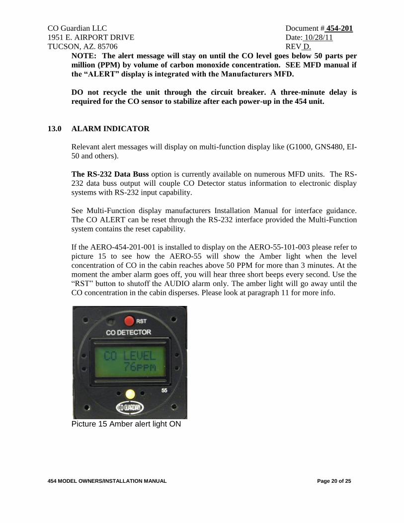
If the AERO-454-201-001 is installed to display on the AERO-55-101-003 please refer to
picture 15 to see how the AERO-55 will show the Amber light when the level
concentration of CO in the cabin reaches above 50 PPM for more than 3 minutes. At the
moment the amber alarm goes off, you will hear three short beeps every second. Use the
“RST” button to shutoff the AUDIO alarm only. The amber light will go away until the
CO concentration in the cabin disperses. Please look at paragraph 11 for more info.
Picture 15 Amber alert light ON
CO Guardian LLC Document # 454-201
1951 E. AIRPORT DRIVE Date: 10/28/11
TUCSON, AZ. 85706 REV D.
454 MODEL OWNERS/INSTALLATION MANUAL Page 21 of 25
14.0 CARBON MONOXIDE LEVEL INDICATION
Aero-454 can detect Carbon Monoxide from as low as 10 PPM. Aero-454 will trigger an
alarm for CO long before the pilot/passengers can be affected by exposure to CO.
The effect of CO level on the human body is linked to the duration of exposure to CO.
Our units are designed to set off CO alarms in progressively shorter durations as the
concentration of CO increases. The intention is to prevent a false alarm when the CO
level poses no danger, but at the same time ensure full protection when the level starts
becoming dangerous.
NOTE: Aero-454 IS design to comply with FAR 23.831(a) and SAE Standard AS 412B.
15.0 HOW THE AERO-454 PROTECTS YOU AGAINST CO POISONING
The CO display page on the MFD shows the CO level in PPM (Parts per million). The
Aero-454 can display CO from 10 PPM to 999 PPM. (For any level above 999 PPM, the
display will register only 999). The alarm will sound within 5 minutes if the CO level
stays above 75 +/- 5 PPM. If the CO level rises above 400 PPM, the alarm will trigger
instantly. (However, if the level reaches 400 PPM or above inside the cabin, it will still
take a few seconds for the CO to reach the sensor inside the unit. Therefore it may take a
few additional seconds for the unit to set off the CO alarm).
16.0 TECHNICAL SPECIFICATIONS
- Power supply: 12 - 30 V DC
- Power consumption: 2 W
- Current drawn: 300 milli-amps
- Fuse: Use GMI type, fast acting fuse 2A 250V
- Temperature range: -20C to +65C
- Humidity range: 10-90% RH (Non condensing)
- Sensor calibration: Each unit calibrated at 75 PPM
- Weight of the unit is approximately 4 oz.
CO Guardian LLC Document # 454-201
1951 E. AIRPORT DRIVE Date: 10/28/11
TUCSON, AZ. 85706 REV D.
454 MODEL OWNERS/INSTALLATION MANUAL Page 22 of 25
17.0 MAINTENANCE INSTRUCTIONS
The carbon monoxide detector and associated equipment consist of certain parts, which
do not require periodic scheduled servicing or periodic scheduled preventive
maintenance. At every power up the system will go through a self-diagnostic check.
WARNING: If all Models show a flashing remote Amber light every 4 seconds,
return the unit to CO Guardian for repair or replacement. See MFG Manual if
Remote light is displayed on the MFD.
Field repair or service is allowable on all of the installed system components except
for the CO Detector Indicator itself. The CO Detector must be returned to CO
Guardian, LLC for all service.
The aircraft wiring harness, circuit breaker shall be included maintenance instructions for
general visual inspections for system integrity, installation security, corrosion and
chaffing.
CO Guardian LLC Document # 454-201
1951 E. AIRPORT DRIVE Date: 10/28/11
TUCSON, AZ. 85706 REV D.
454 MODEL OWNERS/INSTALLATION MANUAL Page 23 of 25
18.0 CARBON MONOXIDE DETECTOR SCHEDULED MAINTENANCE
Scheduled Maintenance Program tasks to be added to the aircraft operator's appropriate
airplane maintenance program are as follows:
MAINTENANCE TASK INTERVAL
a. Recommended Periodic Scheduled Servicing Tasks: None Required.
b. Recommended Periodic Scheduled Preventative Maintenance
test/checks to determine system condition and/or latent failures:
Note:
Be sure the vent on the faceplate is free of obstructions.
Any failures of the system are evident to the pilot through a
flashing remote Amber light approximately every 4
seconds.
Each time the unit is turned ON.
c. Recommended Periodic Inspections: None Required.
d. Recommended Periodic Structural Inspections None Required.
e. Required CO Sensor replacement and calibration. At end of Service Life (Reference Par. 2.0)
NOTE
The unit must be returned to the manufacturer for sensor
replacement and recalibration at the end of the unit service life.
NO FIELD SERVICE OR OVERHAUL OF MODELS IS AUTHORIZED.
19.0 WEIGHT AND BALANCE / EQUIPMENT LIST
The Aero 454’s CO Detector installation weighs 4 oz. Reference the aircraft weight and
balance manual for moment arm.
CO Guardian LLC Document # 454-201
1951 E. AIRPORT DRIVE Date: 10/28/11
TUCSON, AZ. 85706 REV D.
454 MODEL OWNERS/INSTALLATION MANUAL Page 24 of 25
20.0 LIMITATIONS
The AERO-454 CO Detector may not replace any existing instrument or indicator
required by the type design or operating limits.
21.0 PERFORMANCE
No Change
22.0 UNIT FAILURE INDICATION:
A failure of the CO Sensor, Temperature Sensor, or the Micro-controller will result in the
following failure indications:
NOTE: SEE MFG manual if the fault data is integrated with the MFG MFD for
fault analysis.
If unit 454 is installed with the AERO 55-101-003 display unit, the 55 unit will
display “CO SENSOR FAIL” on its screen.
In case of a failure indication, attempt to clear the failure condition by resetting the CO
Detector. Should the failure condition continue, remove the CO Detector power by
pulling the CO Detector circuit breaker.
CO Guardian LLC Document # 454-201
1951 E. AIRPORT DRIVE Date: 10/28/11
TUCSON, AZ. 85706 REV D.
454 MODEL OWNERS/INSTALLATION MANUAL Page 25 of 25
23.0 Warranty
WARRANTY COVERAGE: CO GUARDIAN LLC. WARRANTS TO THE ORIGINAL CONSUMER
PURCHASER, THAT THIS DETECTOR WILL BE FREE OF DEFECTS IN MATERIAL AND
WORKMANSHIP FOR A PERIOD OF ONE (1) YEAR FROM DATE OF PURCHASE. THE
MANUFACTURER'S LIABILITY HEREUNDER IS LIMITED TO REPLACEMENT OF THE
PRODUCT, REPAIR OF THE PRODUCT OR REPLACEMENT OF THE PRODUCT WITH A
REPAIRED PRODUCT AT THE DISCRETION OF THE MANUFACTURER. THIS WARRANTY IS
VOID IF THE PRODUCT HAS BEEN DAMAGED BY ACCIDENT, UNREASONABLE USE,
NEGLECT, TAMPERING OR OTHER CAUSES NOT ARISING FROM DEFECTS IN MATERIAL
OR WORKMANSHIP. THIS WARRANTY EXTENDS TO THE ORIGINAL CONSUMER
PURCHASER OF THE PRODUCT ONLY.
Warranty Disclaimers: Any implied warranties arising out of this sale, including but not limited to the
implied warranties of description, merchantability and fitness for a particular purpose, are limited in
duration to the above warranty period. In no event shall the Manufacturer be liable for loss of use of this
product or for any indirect, special, incidental or consequential damages, or costs, or expenses incurred by
the consumer or any other user of this product, whether due to a breach of contract, negligence, strict
liability in tort or otherwise. The manufacturer shall have no liability for any personal injury, property
damage or any special, incidental, contingent or consequential damage of any kind resulting from gas
leakage, fire or explosion.
Some states do not allow limitations on how long an implied warranty lasts, so the above limitation may
not apply to you.
Some states do not allow the exclusion or limitation of consequential or incidental damages, so the above
limitations or exclusions may not apply to you.
Legal Remedies: This warranty gives you specific legal rights and you may also have other rights that
vary from state to state.
Warranty Performance: During the above warranty period, your product will be replaced with a
comparable product if the defective product is returned, postage prepaid, to CO Guardian, Customer
Service Department, 1951 East Airport Drive, Tucson, AZ 85706, together with proof of purchase date.
Please include a note describing the problem when you return the unit. The replacement product will be
in warranty for the remainder of the original warranty period or for six months whichever is longer.
Other than the cost of postage, no charge will be made for replacement of the defective product.
Important: Do not attempt to open unit. If unit is opened, warranty will be void.
Your Carbon Monoxide Alarm is not a substitute for property, disability, life or other insurance of any
kind. Appropriate insurance coverage is your responsibility. Consult your insurance agent.
NOTE
The warranty will be void if the unit is opened or tampered with