Embed Size (px)
Citation preview

Clemson UniversityTigerPrints
All Dissertations Dissertations
5-2016
Carbon Fibers Derived from Dry-Spinning ofModified Lignin PrecursorsMeng ZhangClemson University, [email protected]
Follow this and additional works at: https://tigerprints.clemson.edu/all_dissertations
This Dissertation is brought to you for free and open access by the Dissertations at TigerPrints. It has been accepted for inclusion in All Dissertations byan authorized administrator of TigerPrints. For more information, please contact [email protected].
Recommended CitationZhang, Meng, "Carbon Fibers Derived from Dry-Spinning of Modified Lignin Precursors" (2016). All Dissertations. 1616.https://tigerprints.clemson.edu/all_dissertations/1616

CARBON FIBERS DERIVED FROM DRY-SPINNING OF MODIFIED
LIGNIN PRECURSORS
A Dissertation
Presented to
the Graduate School of
Clemson University
In Partial Fulfillment
of the Requirements for the Degree
Doctor of Philosophy
Chemical Engineering
by
Meng Zhang
May 2016
Accepted by:
Dr. Amod A. Ogale, Committee Chair
Dr. Douglas Hirt
Dr. Christopher Kitchens
Dr. Rajendra Kumar Bordia

ii
ABSTRACT
Cost and environmental concerns arise from the manufacture of carbon fibers
using petroleum-based precursors such as polyacrylonitrile (PAN). Toxic by-products
such as hydrogen cyanide (HCN) are generated during stabilization and carbonization of
PAN-based carbon fibers. These concerns have promoted increasing interest in biomass-
based carbon fibers. As the second most abundant biomass material on the earth, lignin is
being investigated as a potential carbon fiber precursor. Therefore, this research was
focused on converting lignin materials into carbon fibers with enhanced performance
properties.
Since the 1960s, various types of lignin have been investigated as carbon fiber
precursors. Hardwood kraft lignin and organosolv lignin could be converted into carbon
fibers without chemical modification, whereas softwood kraft lignin was very difficult to
convert without suitable modification or plasticization. Strength of most of the carbon
fibers produced from the above lignin precursors were below 800 MPa, which is much
lower than that of commercial carbon fibers derived from PAN precursors. Thus, the
overall goal of this study was to produce lignin-based carbon fibers with enhanced
mechanical properties by a scalable process. The specific objectives were to: (i) identify
different types of lignin precursors for their potential of being carbon fiber precursors; (ii)
study the modified lignin-acetone solutions to establish a range of suitable combinations
of solution concentrations and spinning temperatures; (iii) establish thermal stabilization
and carbonization conditions for lignin-based precursor fibers to enhance the

iii
performance of resulting carbon fibers; and (iv) to develop a UV/thermal dual
stabilization route to increase the speed of stabilization.
The lignin precursors investigated in this study included an organosolv lignin, a
soda lignin, and a softwood kraft lignin. The organosolv lignin was successfully melt-
spun into fibers without any modification of the precursor material. However, it took
more than 200 hours for the thermo-oxidative stabilization step. The infusible soda lignin
was chemically modified by acetylation into a fusible material, but it could not be cross-
linked. The softwood kraft lignin was modified by a similar acetylation reaction and
fractionation method, and the resulting material could be melt-spun into fibers, as the
melt possessed significant thermal stability. The large extent of acetylation of hydroxyl
groups that led to thermal stability also hindered the thermo-oxidative stabilization.
Consequently, the melt-spinning approach was abandoned. Instead, to preserve more
hydroxyl groups within the precursor material, the acetic anhydride amount used in
acetylation of the softwood kraft lignin was reduced from 15 to 0.66 ml per gram lignin.
As indicated by FTIR spectroscopy, the hydroxyl peak was significantly increased. In
addition, the weight gain of lignin after reaction was reduced from 18% to 5%, indicating
a partial acetylation of the hydroxyl groups in softwood kraft lignin. The resulting
acetylated softwood kraft (Ace-SKL) lignin could be dry-spun using acetone as solvent,
and the fibers could be thermo-oxidatively stabilized.
The rheology of Ace-SKL/acetone solutions prepared with different solid contents
was investigated for the purpose of dry-spinning into precursor fibers. The solution
viscosity was investigated at high shear rates encountered during fiber spinning. The

iv
solutions displayed a significant shear-thinning behavior at various temperatures studied
with power-law exponents ranging from 0.33 to 0.82, confirming the macromolecular
nature of the Ace-SKL lignin/acetone solutions. As expected, elevated temperatures led
to lower viscosities and facilitated extrusion at moderate pressures.
Dry-spinning was performed over a range of concentrations (1.85 to 2.15 g/ml
acetone) and appropriate temperatures (25-50°C). It was observed that all of the resulting
dry-spun lignin fibers displayed a crenulated surface pattern, with increased crenulation
achieved for fibers spun at higher temperatures. Presence of some doubly-convex and
sharp crevices was found on fibers produced from solutions containing lower
concentrations (1.85 and 2.00 g lignin/mL solvent). In contrast, no crevices were found
on the fibers obtained from the concentrated solution (2.15 g/mL), likely due to the
reduced extent of solvent out-diffusion. Dry-spinning at room temperature was also
performed to obtained fibers with relatively smooth surface, but the pressure drop was
excessive. The results above have established temperature/concentration combinations
for dry-spinning of Ace-SKL. About 30% larger surface area could be achieved in the
crenulated lignin fibers (as compared with equivalent circular fibers), indicating the
potential advantage of such biomass-derived fibers in providing larger fiber/matrix
bonding area when used in composites.
During thermo-oxidative stabilization, tension of about 2000-2500 g/(g/cm) was
applied on fiber tows that led up to 800% extension. In the carbonization step, tension
was also applied using a customized graphite rack and tungsten weights, and stabilized
Ace-SKL fibers were successfully carbonized at 1000°C. It was found that the load

v
needed to be above 20150 g/(g/cm) to prevent shrinkage of fiber tows. Both tensile
strength and modulus were measured as a function of extension during carbonization
(EDC). As expected, Ace-SKL carbon fibers with larger EDC had better mechanical
properties due to preserved molecular orientation. Carbon fibers derived from lignin
precursor fibers obtained from 2.15 g/ml Ace-SKL solution (6 μm diameter) displayed a
tensile modulus, strength, and strain-to-failure values of 52 ± 2 GPa, 1050 ± 70 GPa, and
2.0 ± 0.2%, respectively. These values are amongst the best reported for lignin-based
carbon fibers. In contrast, the carbon fibers spun from 2.00 g/ml solution with sharp
crevices displayed a reduced tensile strength of 790 ± 80 MPa due to occlusion-type
defects formed by sharp crevices during spinning. The Ace-SKL carbon fibers displayed
low crystallinity as investigated by Wide Angle X-ray Diffraction (WAXD) and Raman
spectroscopy. The crenulated surface from dry-spinning was preserved, which can
provide a larger specific interfacial area for enhanced fiber/matrix bonding in composite
applications. Above results elucidate the importance of precursor composition and
processing conditions on microstructure and properties of resulting precursor and carbon
fibers.
A limitation of the partially acetylated lignin (i.e., with a fraction of hydroxyl
moieties converted to acetyl groups) is the slow heating rate during thermal stabilization,
which required up to 40 hours due to the slow heating rate needed to prevent the fibers
from becoming tacky and sticking to each other. Therefore, a rapid strategy of dual UV-
thermoxidative stabilization was developed. The fibers undergo UV-induced reaction
close to the surface in a short duration (15 min) such that they can be subsequently

vi
stabilized at a rapid heating rate without fibers fusing together. The glass transition
temperature of UV irradiated fibers was about 15°C higher than that of fibers without UV
treatment. This strategy reduces the total stabilization time significantly from 40 to 4
hour. Stabilized fibers were successfully carbonized at 1000°C and resulting carbon
fibers displayed a tensile strength of 900 ± 100 MPa, which is amongst the highest
reported for carbon fibers derived from rapidly stabilized lignin precursors.
In summary, the results from this study established a route for dry-spinning of
partially acetylated softwood kraft lignin into precursor fibers and successful stabilization
and carbonization. This precursor could be dissolved in acetone for dry-spinning. The
lignin/acetone solutions were investigated to establish suitable concentration/temperature
combinations for dry-spinning. The dry-spun precursor fibers were thermally treated
under tension to convert into a carbon fiber with tensile strength of more than 1 GPa.
Those carbon fibers possessed crenulated surface which could provide larger fiber/matrix
interfacial bonding area for composite applications. Furthermore, UV/thermal dual
stabilization was developed to reduce the time duration of stabilization.

vii
DEDICATION
This work is dedicated to my family who supported me unconditionally during
these years.

viii
ACKNOWLEDGEMENTS
I would like to extend my sincere gratitude to everyone who supported and helped
me to successfully complete this work.
First of all, I want to thank my husband Xiaozhen, for his unconditional love and
support during these years. It is impossible to complete this work without his companion.
Then I want to thank my daughter Katie, for cheering me up with her precious smile.
Also, I would like to thank my parents, Daping Zhang and Shuxia Li for the
unconditional support. Also, I want to thank my grandma Wenqiu Gao, and all of my
aunts, uncles, and cousins, for their valuable support.
I want to express my appreciation to everyone in Dr. Ogale’s research group:
Youngpyo, Marlon, Becky, Byron, Sam, Ozgun, Jing, Victor, Bushra, and all the
undergraduate students used to work in our group, for their friendship and help during my
study. Especially, I would like to thank my advisor Dr. Ogale, for all his invaluable
guidance, encouragement, and insights during this work. Also, I want to thank to Army
Research Lab for providing ample funding for this project.
I want to thank Dr. Hirt, Dr. Kitchens, and Dr. Bordia, for their guidance and
suggestions to this work. Also, I want to thank Dr. Bruce, Dr. Husson, Dr. Getman, and
Dr. Thies, for their help during my PhD study, as well as Joy, Terri, Diana, and Bill for
all the friendship and support from ChBE department.

ix
Finally, I want to thank for the friendship, support and help from all of other
Clemson friends: Jingxiang, Ming, Yu-Tung, Jack, Yi, Feng, Juan, Tianyu, Difeng,
Hongzhen, Mingzhe, Qiuchen, Yijie, Xuejiao, Weigao, and Yang.

x
TABLE OF CONTENTS
Page
TITLE PAGE .................................................................................................................... i
ABSTRACT ..................................................................................................................... ii
DEDICATION ............................................................................................................... vii
ACKNOWLEDGEMENTS ......................................................................................... viii
LIST OF TABLES ........................................................................................................ xiii
LIST OF FIGURES ...................................................................................................... xiv
CHAPTER
1. INTRODUCTION...............................................................................................1
1.1 Overview of carbon fibers ................................................................1
1.2 Carbon Fiber Precursors .................................................................4
1.2.1 Polyacrylonitrile (PAN) ...........................................................4
1.2.2 Mesophase pitch-based carbon fibers .....................................11
1.2.3 Rayon-based carbon fibers .....................................................13
1.3 Overview of lignin ...........................................................................14
1.3.1 Chemical structure of lignin ...................................................15
1.3.2 Lignin derived from different pulping methods .....................16
1.3.3 Carbon fibers derived from lignin precursors ........................19
1.4 Objectives.........................................................................................25
2. INVESTIGATION OF VARIOUS LIGNINS AS CARBON FIBER
PRECURSORS .................................................................................................27
2.1 Introduction .....................................................................................27
2.2 Experimental ...................................................................................28
2.2.1 Analysis of lignin samples .....................................................28
2.2.2 Acetylation Reaction ..............................................................30
2.2.3 Carbon fiber preparation ........................................................31

xi
Table of Contents (Continued)
Page
2.2.4 Characterization of carbon fibers ...........................................31
2.3 Results and Discussion ....................................................................32
2.3.1 Soda lignin precursor ..............................................................32
2.3.2 ECN organosolv lignin ...........................................................38
2.3.3 SKL lignin ..............................................................................42
2.4 Conclusions ......................................................................................50
3. EFFECT OF TEMPERATURE AND CONCENTRATION ON
FLOW CHARACTERISTICS OF ACETYLATED-LIGNIN
SOLUTIONS .....................................................................................................52
3.1 Introduction .....................................................................................52
3.2 Experimental ...................................................................................53
3.2.1 Materials .................................................................................53
3.2.2 Rheology and spinning ...........................................................55
3.3 Results and Discussion ....................................................................58
3.3.1 Viscosity and flow characteristics ..........................................58
3.3.2 Fiber spinning .........................................................................60
3.4 Conclusions ......................................................................................70
4. CARBON FIBER DERIVED FROM ACE-SKL: HEAT
TREATMENT AND CARBON FIBER CHARACTERIZATION .............72
4.1 Introduction .....................................................................................72
4.2 Experimental ...................................................................................73
4.2.1 Thermal stabilization ..............................................................73
4.2.2 Carbonization .........................................................................74
4.2.3 Characterization ......................................................................77
4.3 Results and Discussion ....................................................................80
4.3.1 Tension effect .........................................................................80
4.3.2 Microstructure ........................................................................87
4.4 Conclusions ....................................................................................100

xii
Table of Contents (Continued)
Page
5. UV-ASSISTED STABILIZATION OF ACE-SKL PRECURSOR
FIBERS ............................................................................................................102
5.1 Introduction ...................................................................................102
5.2 Experimental .................................................................................104
5.2.1 UV/Thermal dual stabilization .............................................104
5.2.2 Characterization ....................................................................106
5.3 Results and Discussion ..................................................................107
5.3.1 FTIR .....................................................................................107
5.3.2 Thermal analysis ...................................................................110
5.3.3 GPC ......................................................................................113
5.3.4 UV/Thermal dual stabilization .............................................114
5.4 Conclusions ....................................................................................119
6. CONCLUSIONS AND FUTURE WORK ....................................................121
6.1 Conclusions ....................................................................................121
6.2 Future Work ..................................................................................123
REFERENCES ................................................................................................127
APPENDICES .................................................................................................135
A.1 Bagley correction of Ace-SKL solutions .......................................136
A.2 Elongational viscosity measurement ..............................................140
A.3 Ace-SKL as-spun fibers shape analysis using SEM ......................142
A.4 Compliance Measurement ..............................................................147

xiii
LIST OF TABLES
Table Page
1.1 Comparison of properties between carbon fibers and other materials (4-7) ...............2
1.2 A summary of tensile properties of carbon fibers obtained from different
precursors in prior studies ..............................................................................24
2.1 Carbon fiber potential of lignin and modified lignin precursors ..............................51
3.1 Ash content resulting after different washing conditions .........................................54
3.2 Elemental analysis result of SKL before and after wash ..........................................54
3.3 Fiber surface characteristics of Ace-SKL as-spun fibers at various concentrations
and appropriate processing temperatures. CN is the average number of
crenulations on each fiber, and SR is the ratio of the enhanced surface area
of the crenulated fibers compared with circular fibers possessing equal
cross-sectional area.........................................................................................67
4.1 Ace-SKL carbon fiber properties of fiber processed with and without tension .......87
A.1 Original data obtained from capillary rheometer for Bagley correction ................136

xiv
LIST OF FIGURES
Figure ............................................................................................. Page
1.1 A schematic of carbon fiber manufacturing process ...................................................3
1.2 Monomers copolymerized with acrylonitrile to form PAN-based carbon fiber
precursor (2) .....................................................................................................5
1.3 Schematic of typical process for wet-spinning of PAN precursors (14) ....................6
1.4 As-spun fibers from PAN precursor. Reproduced with permission from (15). ..........6
1.5 Cyclization reaction during stabilization of PAN based precursors (14) ...................8
1.6 Representative SEM micrographs of PAN-based carbon fibers. Reproduced with
permission from (19). .......................................................................................9
1.7 Schematic 3-D structural model of Fortafil 5-Y PAN-based carbon fibers with
345 GPa of tensile modulus. Reproduced with permission from (20). ............9
1.8 Structure of lignin, cellulose, PAN, and mesophase pitch. The first three
precursors generate carbon fibers with noncrystalline/turbostratic structure,
whereas meshopase pitch generates graphitic/crystalline structure (adapted
from (2), (21)).................................................................................................10
1.9 Schematic model of the carbonaceous mesophase. Reproduced with permission
from (27).........................................................................................................11
1.10 Chemical structure of cellulose ...............................................................................13
1.11 Simplified kraft pulping process .............................................................................17
2.1 The structure of the heating furnace in METTLER TOLEDO FP900
Thermosystem ................................................................................................29

xv
List of Figures (Continued) ............................................................ Page
2.2 Residue of Soda lignin after heating at 250°C for 5 minutes ...................................33
2.3 TGA curve of soda lignin .........................................................................................34
2.4 Transient shear viscosity of Ace-Soda at 148 °C .....................................................35
2.5 As-spun fibers of Ace-Soda ......................................................................................36
2.6 SP change with devolatilization time for Ace-Soda .................................................36
2.7 Transient shear viscosity of Ace_Soda with 0, 2, and 2.5 h of heat treatment. ........38
2.8 Transient shear viscosity of ECN lignin at 1 and 3 s-1
, 160°C. ................................39
2.9 Thermogravimetric analysis of ECN lignin ..............................................................39
2.10 ECN lignin fibers as seen on the take-up wheel (left) and as observed by light
microscopy in the transmission mode (right) .................................................40
2.11 The temperature profile during thermal stabilization of ECN lignin fiber .............41
2.12 SEM micrographs of carbon fibers derived from ECN lignin ................................42
2.13 Transient shear viscosity of (a) Ace-SKL and (b) 75% acetic acid extracted Ace-
SKL ................................................................................................................44
2.14 (a) SEM micrograph of as-spun Ace-SKL fibers; (b) Fused Ace-SKL fibers after
thermal stabilization .......................................................................................45
2.15 FTIR spectra of SKL at different acetylation levels ...............................................46
2.16 Softening points of Ace-SKL with different reaction composition ........................47
2.17 DSC of Ace-SKL with different reaction composition ...........................................48
2.18 Ace_SKL filaments manually drawn from acetone solution ..................................49
3.1 Bagley plot of 2.15 g/ml Ace-SKL solution .............................................................57

xvi
List of Figures (Continued) ............................................................ Page
3.2 Shear viscosity of Ace-SKL solutions over a range of shear rates. (a) Viscosity
obtained after Bagley correction using capillaries with L/D = 5, 15 and 20;
(b) Viscosity obtained from capillaries with L/D = 5, without Bagley
correction. .......................................................................................................60
3.3 SEM images of Ace-SKL lignin fibers from a 1.85 g/mL solution, at various
spinning temperatures.....................................................................................62
3.4 Magnified SEM image of a sharp crevice on the surface of as-spun lignin fiber
obtained from 1.85 g/mL solution. .................................................................63
3.5 SEM images of Ace-SKL lignin fibers from a 2.00 g/mL solution, at various
spinning temperatures.....................................................................................64
3.6 Ace-SKL lignin fibers from dry-spinning of 2.15 g/mL solution at various
spinning temperatures.....................................................................................66
3.7 As-spun fibers from dry-spinning of Ace-SKL/acetone solutions at room
temperature at two different concentrations: (a) 2.15 g/ml and (b) 2.00 g/ml70
4.1 Stabilization of Ace-SKL fiber tow under tension ...................................................74
4.2 Mounting of stabilized fiber tows with Ceramabond 671 ........................................75
4.3 Carbonization of Ace-SKL fiber tow under tension using customized graphite
rack .................................................................................................................76
4.4 Cesium formate solution prepared with density floats .............................................77
4.5 Stretched fiber tows after thermal stabilization under tension ..................................81
4.6 Fiber length change at different temperatures during one batch of stabilization ......82

xvii
List of Figures (Continued) ............................................................ Page
4.7 Extension during carbonization of Ace-SKL fibers under different level of load ....84
4.8 Tensile strength and modulus of Ace-SKL carbon fibers under various levels of
tension during carbonization. .........................................................................86
4.9 Raman spectra of Ace-SKL carbon fibers carbonized at 2400 and 1000°C.
Intensity values on the ordinate scale are in arbitrary units. ..........................89
4.10 A 2-D wide-angle X-ray diffraction pattern after Fraser-correction ......................91
4.11 Wide-angle x-ray diffraction of Ace-SKL carbon fibers. Intensity values on the
ordinate scale are in arbitrary units. Azimuthal scans have been shifted
vertically for visual clarity. The encircled peaks (a) are silicon peaks. .........92
4.12 Wide-angle x-ray diffraction of carbon fibers derived from Ace-SKL, mesophase
pitch, and PAN precursors..............................................................................93
4.13 SEM of Ace-SKL carbon fibers from 2.15 g/ml Ace-SKL solution spun at 45°C .95
4.14 SEM of Ace-SKL carbon fibers carbonized at 2400°C ..........................................96
4.15 Carbon fibers obtained from precursor fibers dry spun at 50°C of 2.00 g/ml
solution ...........................................................................................................97
4.16 Representative stress-strain curves of single carbon fibers, obtained from two
different precursor solution concentrations (2.00 and 2.15 g/ml), displaying
an almost linear/elastic response to failure. ....................................................99
5.1 Ace-SKL fiber tows before stretching (left) and after stretching (right) ................104
5.2 Fiber tows mounted on UV irradiation fixture .......................................................105
5.3 Fiber tows in the UV chamber for irradiation .........................................................105

xviii
List of Figures (Continued) ............................................................ Page
5.4 FTIR spectra of Ace-SKL after different durations of UV treatment .....................108
5.5 Relative intensity change of 1740 cm−1
and 1512 cm−1
peaks as a ratio of 1369
cm−1
peak after UV treatment for different durations ..................................109
5.6 After thermal-oxidation up to 160°C at a heating rate of 1.2°C/min, (a) with prior
UV treatment of fibers; (b) control fibers ....................................................110
5.7 SEM image of Ace-SKL control fibers (without prior UV treatment) heated
rapidly at 1.2°C /min that led to multiple fibers fusing together ..................111
5.8 DSC thermograms of various lignin-based precursor fibers thermally treated up to
different temperatures. Solid curves: thermograms of fibers after UV
irradiation; dashed curves: thermograms of control fibers without UV
exposure........................................................................................................112
5.9 Tg shift of UV treated and control fibers as a function of thermal stabilization
temperature ...................................................................................................112
5.10 GPC chromatograms of Ace-SKL fiber samples with different UV treatment
time ...............................................................................................................114
5.11 SEM micrographs of stretched as-spun Ace-SKL fibers at (a) low and (b) high
magnification levels. ....................................................................................114
5.12 SEM images of UV-treated Ace-SKL fibers at (a) low and (b) high
magnification levels. ....................................................................................115

xix
List of Figures (Continued) ............................................................ Page
5.13 SEM images of stabilized Ace-SKL fibers: (a) fibers without any prior UV
treatment stabilized at a slow rate of 0.2°C/min; (b) fibers with 15-min
prior UV treatment stabilized at a fast rate of 1.2°C/min .............................116
5.14 Carbonized Ace-SKL fibers from (a) UV/thermal dual stabilization (b) slow
thermal stabilization. ....................................................................................119
A.1 Bagley plots of various concentration / temperature combinations .......................138
A.2 Effective extensional viscosity of 2.15 g/ml acetone Ace-SKL solution measured
at 25°C ..........................................................................................................140
A.3 Adjustment of single fiber alignment using “rotation” and “tilt” feature of SEM 142
A.4 “Rotation” and “tilt” feature in SEM software ......................................................143
A.5 “Freehand shape measuring tool” in Quartz PCI. ..................................................144
A.6 Example group of images for Ace-SKL as-spun fibers (dry-spun from 2.00 g/ml
acetone solution under 40°C) .......................................................................145
A.7 Compliance 𝐶 plot against 𝑙/𝐴 ..............................................................................147

1
CHAPTER ONE
INTRODUCTION
1.1 Overview of carbon fibers
Carbon fibers possess excellent strength, stiffness, low density, and outstanding
electrical and thermal conductivities. Also, they are chemically stable and fire-retardant
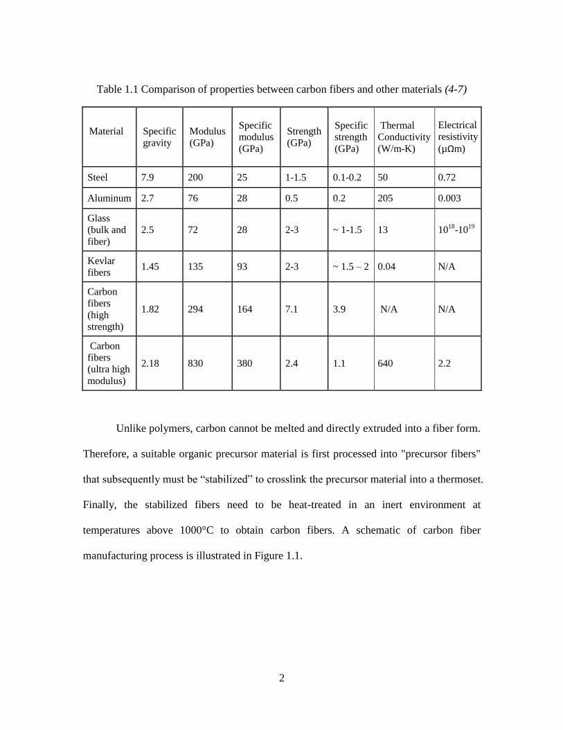
(1-3). In Table 1.1, mechanical properties and specific gravity of different materials are
listed for comparison (4-7). When compared with metals like steel, carbon fibers possess
an order of magnitude higher specific modulus and strength. When compared on an
absolute basis with strong polymer, i.e. Kevlar fibers, they display much higher modulus
and strength. Overall, carbon fibers possess an excellent combination of modulus,
strength, and conductivities as compared with other materials.
2
Table 1.1 Comparison of properties between carbon fibers and other materials (4-7)
Material
Specific
gravity
Modulus
(GPa)
Specific
modulus
(GPa)
Strength
(GPa)
Specific
strength
(GPa)
Thermal
Conductivity
(W/m-K)
Electrical
resistivity
(µΩm)
Steel 7.9 200 25 1-1.5 0.1-0.2 50 0.72
Aluminum 2.7 76 28 0.5 0.2 205 0.003
Glass
(bulk and
fiber)
2.5 72 28 2-3 ~ 1-1.5 13 1018
-1019
Kevlar
fibers 1.45 135 93 2-3 ~ 1.5 – 2 0.04 N/A
Carbon
fibers
(high
strength)
1.82 294 164 7.1 3.9 N/A N/A
Carbon
fibers
(ultra high
modulus)
2.18 830 380 2.4 1.1 640 2.2
Unlike polymers, carbon cannot be melted and directly extruded into a fiber form.
Therefore, a suitable organic precursor material is first processed into "precursor fibers"
that subsequently must be “stabilized” to crosslink the precursor material into a thermoset.
Finally, the stabilized fibers need to be heat-treated in an inert environment at
temperatures above 1000°C to obtain carbon fibers. A schematic of carbon fiber
manufacturing process is illustrated in Figure 1.1.

3
Figure 1.1 A schematic of carbon fiber manufacturing process
The first carbon fiber or carbon filament was produced by Thomas Edison in 1879
as the heated filament in a light bulb (3). A bamboo sliver (cellulose) was baked at high
temperature and formed an all-carbon filament. However, the first carbon fiber with
relatively good mechanical properties was invented by Roger Bacon in the late 1950s by
growing graphite whiskers using vapor deposition in a high pressure carbon arc (8).
Subsequently, Bacon patented another process for carbonization of rayon to produce
carbon fibers (9). Almost at the same time, Shindo used polyacrylonitrile (PAN) as
precursor material and successfully produced carbon fibers (10). A few years later,
carbon fibers were produced from another type of precursor, pitch (11). All of the three
precursor materials (PAN, pitch, and rayon) are used for commercial production of
carbon fibers, with PAN accounting for over 90% of carbon fibers produced currently
(12).
Crosslinkable
Precursor
Fibers
Crosslinked
Fibers
Spinnable
High purity
(Low ash)
content
Chemical synthesis
Separation/Purification
Pretreatment
Melt-spinning
Wet-spinning
Dry-spinning
Crosslinking/
Thermo-oxidative
Stabilization Above 200°C
Air atmosphere
Carbonization (above 1000°C)
Graphitization (above 2400°C)
In inert
atmosphere
Carbon
Fibers
Raw
material Precursor

4
1.2 Carbon Fiber Precursors
1.2.1 Polyacrylonitrile (PAN)
As noted above, high-strength carbon fibers used in current structural composite
applications are almost exclusively derived from PAN precursor fibers (1, 2). These
precursors are typically copolymers of acrylonitrile and a small amount of other
monomers as shown in Figure 1.2 (2). The carbon yield of converting a PAN precursor to
carbon fibers is about 45%.
PAN precursor decomposes at a temperature lower than its melting temperature (2,
13). Therefore, it must be converted into fibers via wet-spinning process, as illustrated in
Figure 1.3 (14). A solution containing 15-30 wt% PAN is extruded out of a spinneret into
a coagulation bath that extracts the solvent out of the extruded solution to solidify the
filaments. The mass transfer rate in this step is controlled by temperature and
concentration of the coagulant, which leads to differences in the cross-section of
precursor fibers. After coagulation, the fibers are subjected to multiple steps of washing
and stretching to remove the residual solvent and achieve smaller diameter, respectively.
Due to collapse of fiber skin during coagulation, the cross-section of PAN precursor
fibers typically has the shape of kidney-beans or dog-bones (2, 15) (Figure 1.4).

5
Monomers Structure
Acrylic Acid
Itaconic Acid
Methacrylic Acid
Methyl Acrylate
Vinyl Acetate
Acrylonitrile
Figure 1.2 Monomers copolymerized with acrylonitrile to form PAN-based carbon fiber
precursor (2)

6
Figure 1.3 Schematic of typical process for wet-spinning of PAN precursors (14)
Figure 1.4 As-spun fibers from PAN precursor. Reproduced with permission from (15).
Solution
Storage Coagulation
bath Wash bath Wet-draw Wash bath
Dry and
heated-draw Wind-up
Thermal
oxidative
stabilization
Carbonization

7
In addition to wet-spinning, another solution spinning method to obtain PAN
precursor fibers is dry-spinning. In dry-spinning, a PAN copolymer solution is extruded
into a hot gas chamber to evaporate the solvent. The temperature of evaporation chamber
and hot gas composition need to be well monitored since it will control the mass transfer
rate and fiber structure (2, 16). Another route to form PAN fibers is melt-assisted
spinning in which the PAN precursor and a plasticizer is fed into extruder. Finally, with
significant comonomer content, the melt-spinning can be performed (2, 17).
Stabilization of PAN-based precursor fibers is carried out at 220-280°C in air
atmosphere under tension (18). The primary reaction in this step is cyclization as shown
in Figure 1.5. In this reaction, the nitrile groups on the polymer chain cyclized and the
material became infusible. It can be seen that some toxic by-products, such as hydrogen
cyanide (HCN), are generated in this step (14). Once the precursor fibers have been
stabilized, carbonization is performed at temperatures ranging from 1000 to 2800°C still
in the presence of tension. In this step, HCN also evolved. Accompanied with the fact
that large amount of organic solvent is needed during coagulation, the production of
PAN-based carbon fiber is not an environmentally friendly procedure.

8
Figure 1.5 Cyclization reaction during stabilization of PAN based precursors (14)
After carbonization, the kidney-bean or dog-bone cross-section shape is preserved
as displayed in Figure 1.6 (19). The microstructure of PAN-based carbon fibers is
fibrillar. Figure 1.6 is a schematic 3-D structural model of a PAN-based carbon fibers
(20). In Figure 1.7, the ribbon like undulation is displayed. Also, it was found that the
undulation structure was highest in the center and lowest near the skin part. As displayed
in Figures 1.7 and 1.8, PAN-based carbon fibers display extensively folded turbostratic
layers and low degree of graphitization, and the turbostratic layers are not highly aligned
along the fiber axis.

9
Figure 1.6 Representative SEM micrographs of PAN-based carbon fibers. Reproduced
with permission from (19).
Figure 1.7 Schematic 3-D structural model of Fortafil 5-Y PAN-based carbon fibers with
345 GPa of tensile modulus. Reproduced with permission from (20).

10
Figure 1.8 Structure of lignin, cellulose, PAN, and mesophase pitch. The first three
precursors generate carbon fibers with noncrystalline/turbostratic structure, whereas
meshopase pitch generates graphitic/crystalline structure (adapted from (2), (21))

11
1.2.2 Mesophase pitch-based carbon fibers
Mesophase pitch could be obtained by polymerization from a petroleum or coal-
tar pitch. When heated up to 400-450°C, the isotropic pitch transforms into a mesophase
or liquid crystalline phase (22). Also, it could be synthesized from pure aromatic
hydrocarbons such as naphthalene and methylnaphthalene (23). Another way to produce
mesophase pitch is by extracting a portion of an isotropic pitch and heating the solvent
insoluble portion to 230°C to 400°C (2, 24-26). Figure 1.9 is a schematic model of
carbonaceous mesophase that shows the nematic liquid-crystal structure (27). The
average molecular weight of a mesophase pitch is around 1000 (2).
Figure 1.9 Schematic model of the carbonaceous mesophase. Reproduced with
permission from (27).
In the melt-spinning process of mesophase pitch, the solid pitch is fed into an
extruder and heated to produce a melt. Then the molten pitch is pumped into a die head
and extruded through spinnerets. As the molten pitch exits the spinneret, it is drawn and

12
solidified in air at the same time, developing a highly oriented molecular structure along
the fiber axis. The spinning temperature needs to be very carefully controlled due to the
extreme temperature sensitivity of mesophase pitch viscosity (2, 28, 29).
The mesophase pitch precursor fibers need to be thermally stabilized at a
temperature below its softening point in air environment to prevent fusing of fibers. Thus,
a precursor with higher softening point is desired to allow higher stabilization
temperature and shorter stabilization time (4). In addition, fiber diameter is another
parameter that controls the total reaction time during stabilization due to the diffusion of
air from fiber surface into the core. Normally, the as-spun fibers are heated to 250-300°C
and held for a period ranging from 3-30 h (2, 4).
Carbonization of stabilized mesophase pitch precursor fibers usually comprises
two steps. First, a pre-carbonization step consists of a few minutes at 900-1000°C in
order to reduce the rate of gases evolution. Second, carbonization or graphitization is
conducted between 1200-3000°C. For mesophase pitch-based carbon fibers, the tensile
strength increases with carbonization temperature until a maximum is reached at about
1500°C. Carbon fibers obtained at high heat treatment temperatures of 2400-3000°C have
a higher modulus compared to fibers treated at the lower temperatures (4).
Pitch-based carbon fibers display more variation in microstructures compared
with their PAN-based counterparts. Due to the highly oriented graphitic structure as
displayed in Figure 1.8 (presented earlier), the tensile modulus of mesophase pitch-based
carbon can be as high as 830 GPa (30).

13
1.2.3 Rayon-based carbon fibers
The chemical structure of cellulose is displayed in Figure 1.10. The carbon
content is 44% and the carbon yield is only about 25%. As noted earlier, it was the
precursor material for the first carbon fiber produced by Edison for his light bulb. Natural
cellulose fibers, such as cotton or flax, in that native state are not good precursors for
structural carbon fibers due to their discontinuous character (31). Instead, regenerated
cellulose fibers, such as rayon, can serve as precursors. However, only a small fraction
(~1%) of world production of carbon fibers is rayon based (2).
Figure 1.10 Chemical structure of cellulose
Rayon precursor fibers are produced from a wet-spinning process. Cellulose was
mixed with a basic solution and treated with CS2 to form cellulose xanthate. Cellulose
xanthate is then dissolved in NaOH and the solution is extruded through spinneret
followed by coagulation in a sulfuric acid solution. Cellulose xanthate hydrolyzed in the
acid solution to precipitate the cellulose filaments (2).
14
The rayon precursor fibers were stabilized in air at temperatures as high as 400°C.
Pyrolysis progressed as heating continues. After oxidation, they were carbonized under
similar condition to those of PAN or pitch. In this step, tension is applied to form a
molecular orientation which is lost during pyrolysis. Rayon based carbon fibers
nominally display a turbostratic structure as displayed in Figure 1.8 (presented earlier).
Stretched carbon fibers can achieve a modulus as high as 720 GPa, but this stretching is a
very expensive process (32-34). Therefore, only a small fraction (~1%) of world
production of carbon fibers is rayon based (2).
As noted in section 1.2.1, the vast majority of commercial carbon fibers are
currently produced from polyacrylonitrile (PAN), a synthetic precursor that does not melt,
so its solution-spun fibers can be easily crosslinked (also referred to as “stabilized”) and
subsequently carbonized, as illustrated in Figure 1.1. However, the wet-spinning process
itself involves the use of hazardous solvents, and the nitrile group generates toxic by-
products (viz. hydrogen cyanide) during heat-treatment.(2, 4) The environmental
concerns and related high costs associated with this process can be partially overcome by
using bio-based precursors. Among naturally occurring biomass, lignin are regarded as
potential CF precursors due to their low cost and carbon forming chemical structure.
1.3 Overview of lignin
Lignin is the second most abundant natural polymer on the earth (35). Raw wood
material nominally consists of 40–50% of cellulose, 23–32% of hemicellulose, and 15–30%
lignin (36). It is present in cell walls of vascular plants to impart compressive and flexural

15
strength to the stems. Over 3 x 10¹¹
tons of lignin exits in the biosphere with
approximately 2 x 10¹⁰
tons generated annually (37). In 1838, a French chemist, Anselme
Payne, isolated both cellulose and lignin from wood and identified them as two separate
components (38). Since then, numerous studies have been performed on the
characterization, separation, and application of lignin.
1.3.1 Chemical structure of lignin
Lignin is an amorphous, complex, and random polymer abundant in aromatic
rings. It is a natural polymer generated from the enzymatic polymerization of three
primary precursor units: coniferyl alcohol, sinapyl alcohol, and p-coumaryl alcohol. In
the polymerized form, they were guaiacyl, syringyl, and p-hydroxylphenl (21). A lignin
model structure is shown in Figure 1.8 (presented earlier) (39). One of the typical
building/repeat unit is circled and the commonly used notation of carbon atoms in those
units is displayed (40, 41). Guaiacyl alcohol is found predominately in softwood lignins,
whereas syringyl alcohol is the dominant structure found in hardwood lignins (21). The
content of p-hydroxylphenl is relatively low in both softwood and hardwood lignins, but
occurs more often in annual crops. Above three main structural elements in lignin are
linked together by various carbon-carbon and ether bonds. The β-O-4 linkage is the most
dominant one in all types of lignins (42). In softwood type, about 50% of the linkages are
β-O-4 type, whereas in hardwood type these comprise 60% (21, 43). As indicated by the
arrows in Figure 1.8, lignin, cellulose, and PAN form a nongraphitic or turbostratic
structure within the resulting CFs, whereas a polynuclear aromatic hydrocarbon precursor,

16
mesophase pitch, forms a highly graphitic/crystalline structure after heat treatment above
2400°C (2).
1.3.2 Lignin derived from different pulping methods
The structure and properties of lignins vary based on different plant source they
are separated from, such as hardwood, softwood, wheat straw, or bamboo (44-46).
However, the discussion here will be focused on major types of lignins separated by
different pulping methods, because chemical pulping brings out the most remarkable
differences in the resulting lignin products. Pulping is a process of separating lignin from
cellulose in plant materials to produce pulp for the manufacture of paper or other
products (47).
Soda pulping and kraft pulping (alkaline processes)
In the soda pulping process, sodium hydroxide (caustic soda) is used as the
reactant for making wood pulp at temperature between 130-170°C. Grass species can be
treated at milder conditions including ambient temperatures (48). Thus, the soda process
is mainly used for pulping of non-wood materials.
Kraft pulping is developed based on soda pulping and has become the dominant
commercial process (49). A schematic of the kraft pulping process is displayed in Figure
1.11. It uses sodium hydroxide and sodium sulfide as the chemical for breaking down the
matrix (lignin). Aqueous sodium hydroxide and sodium sulfide (white liquor) is added to
the wood chips. Pulping is performed at pH above 12 at 160-180°C for 0.5-3 h to reduce
the lignin into smaller fragments that are soluble in water/alkaline solution. Cleavages

17
occur on the linkages that hold the phenylpropane units together, which lead to
generation of free phenolic hydroxyl groups in the resulting kraft lignin (50). After
pulping, a waste liquor containing mainly lignin, hemicellulose and inorganic pulping
chemicals is separated from cellulose. The cellulosic pulp is further treated by bleaching,
washing and drying to form paper. This process is suitable for any type of plant material
(51).
Figure 1.11 Simplified kraft pulping process
The waste liquor generated from both soda and kraft pulping is called black liquor.
Lignins can be precipitated by acidification of black liquor. However, the black liquor is
usually concentrated and burned in a recovery boiler to recover the cooking chemicals
and generate energy from burning of lignin (organic matter) (48, 51).
Sulfite pulping (acid processes)
In a traditional sulfite process, a pulping liquor consisting of sulfur dioxide
aqueous solution and suitable bases is prepared. The bases could be hydroxides of
Pulping
Wood Chips: Cellulose
Hemicellulose
Lignin
White liquor: Sodium hydroxide
Sodium sulfide
Cellulose
Black liquor: Lignin
Hemicellulose
Sodium hydroxide
Sodium carbonate…

18
magnesium, sodium, potassium or ammonium. Wood chips are in contact with the
pulping liquor with a pH between 1.5 to 5 at temperatures ranging from 130 to 160°C.
During pulping, carbocations are formed and react with bisulfite ions (HSO3−) to generate
sulfonates as shown below. Lignin is solubilized by the addition of sulfonate groups (51).
R-O-R' + H+ → R
+ + R'OH
R+ + HSO3
− → R-SO3H
After washing, the waste liquor that contains lignosulfonates and cooking
chemicals is called brown liquor. Like black liquor, the brown liquor is concentrated and
burned to provide steam and recover the inorganic chemicals. To recover lignosulfonates
from the brown liquor, a widely used method is the Howard process of adding excess
calcium hydroxide to precipitate calcium lignosulfonates (52).
Solvent pulping
Kraft pulping is a very efficient and versatile process that can be used to treat
different type of raw plant materials, but it suffers from several environmental issues such
as emission of waste water and malodorous products (sulfur containing). Organic solvent
pulping is a good alternative to overcome such problems (53). Multiple studies have been
conducted using various organic solvents such as methanol (54), ethanol (55), acetic acid
(56), etc. One of the well-developed process is the Alcell process using aqueous ethanol
solutions to treat the wood at temperatures from 180-210°C and pressures of 2-3.5 MPa.
Solvent is recovered later by evaporation and condensation (57). Lignin is recovered
from the spent liquor by precipitation. Since there is no addition of inorganic moieties
19
and sulfur during the process, oranosolv lignins usually have higher purity compared with
kraft lignin and lignosulfonates.
1.3.3 Carbon fibers derived from lignin precursors
Carbon fibers first produced from lignin were patented in 1969 by Otani (58). The
patent described both melt-spinning and dry-spinning using different type of lignin
precursors. The strength of carbon fiber produced from melt-spun precursor ranged up to
800 MPa. In the examples for dry-spinning, water or sodium hydroxide aqueous solutions
were used as solvent for both alkali lignin and thiolignin. Carbon fiber produced from
this dry-spinning process possessed strength that ranged only up to 300 MPa.
Since 1990’s, studies have focused on producing carbon fiber from different types
of lignin precursors by melt-spinning. Sudo and Shimizu (59) used methanol to extract
lignin from a steam exploded birch wood and washed out the hemicellulose. Then, the
extracted lignin was modified into a fusible material by hydrogenolysis. Hydrogenoysis
of the lignin led to extensive cleavage of alkyl-aryl ether bonds, and the lignin was
extracted with chloroform and carbon disulfide. The chloroform soluble and carbon
disulfide insoluble fraction was capable of melt-spinning after a heat treatment. The
resulting carbon fibers from this process possessed a tensile strength of 660 MPa and
modulus of 40.7 ± 6.3 GPa. Sudo and coworkers also modified the steam exploded lignin
through phenolysis (60). The tensile strength of carbon fibers derived from phenolyzed
lignin was below 400 MPa.

20
A series of studies have been performed on lignin precursor produced from acetic
acid pulping. A hardwood lignin was extracted using acetic acid (61). This organosolv
hardwood lignin is fusible and could be melt spun without any modification by Uraki et
al. (62), who also separated softwood lignin from acetic acid pulping. However, the
organosolv softwood lignin could not be spun directly due to a large molecular fraction
which was infusible. It was further fractionated with aqueous acetic acid and one of the
fractions with lower molecular weight could be melt spun into fibers (63, 64). However,
the tensile strength of resulting carbon fibers was only 26.4 and 5.8 MPa, from the
organosolv softwood and hardwood lignin fractions, respectively. Kubo et al. also studied
the processibility of a softwood kraft lignin but failed to convert it into a fusible precursor
(64). Based on their fractionation study, the softwood kraft lignin only had 13% of fusible
fractions, which could not be spun due to a remarkably low molecular mass. They
concluded that softwood kraft lignin is not a suitable raw material for thermoforming of
precursor fibers.
Hardwood kraft lignin and Alcell organosolv lignin can be converted into carbon
fibers without any chemical modification (65). To increase spinnability, both types of
lignin were mixed with 3-5% of poly(ethylene oxide) (PEO). Spinning temperatures for
the mixtures could be lowered as the content of PEO increased. The carbon fibers derived
from hardwood kraft ligin and PEO blend had a tensile strength of about 460 MPa. Here
the possibility of converting softwood kraft lignin into carbon fibers was investigated
again. Even with the addition of PEO, the softwood kraft lignin did not soften, instead

21
charring occurred due to the more highly-crosslinked structure compared with hardwood
lignin (65).
Norberg et al. investigated selected grades of softwood and hardwood kraft lignin.
Both grades were further fractionated with ultrafiltration of the black liquors to generated
permeate lignins (66). This particular grade of fractionated softwood kraft lignin was
successfully melt-spun into precursor fibers. Also, 10% of permeate hardwood kraft
lignin was added into the unfractionated softwood kraft lignin as a softening agent to
achieve melt-spinning. The advantage of this process is the fast stabilization achieved in
85 min, which is faster than most of the lignin fiber stabilization reported in literature.
However, the carbonized fibers had large diameters (above 50 μm) and the carbon fiber
strength was not reported. The large cross-section area of those carbon fibers would lead
to poor tensile strength as observed in prior studies (11). In another study reported by
Nordström et al., using the same separation method, the permeate hardwood kraft lignin
was blended with different unpermeated softwood kraft lignin with various ratios. They
found that the suitable spinning temperature of the mixtures decreased as permeate
hardwood fraction increased (67). The tensile strength reported for those lignin based
carbon fibers were all below 400 MPa (68).
Several studies have made attempts to introduce acrylonitrile (AN) or
polyacrylonitrile (PAN) into lignin to develop carbon fibers. Maradur et al. prepared a
copolymer using a hardwood lignin and AN with AN: lignin ratio from 5:5 to 8:2 (69).
The lignin-PAN copolymer was dissolved in DMSO and converted into fibers through
wet-spinning using a coagulation bath containing water. Xia et al. prepared a

22
lignosulfonate-AN copolymer which is also soluble in DMSO and insoluble in water (70).
They conducted wet-spinning using lignosulfonate/PAN mixture and lignosulfonate-AN
copolymer, respectively. Macrovoids were found in the as-spun fibers derived from
lignosulfonate/PAN mixture, acting as defect in the resulting carbon fibers. But the as-
spun fibers obtained from lignosulfonate-AN copolymer were solid without voids. The
resulting carbon fibers from this copolymer displayed a strength of 540 MPa. Similarly,
lignosulfonate/PAN blend solution was prepared for wet spinning (71). The lignin
content used in this study ranged from 15% to 47%. Voids were still observed in the as-
spun fibers.
Qin et al. introduced organoclay (organically modified montmorillonite) into a
pyrolysis lignin as a reinforcement (72). When the organoclay loading was below 1.0
wt%, tensile strength of resulting carbon fibers was improved by 12%. The resulting
carbon fibers in this study had a large diameter (more than 45 µm), and the tensile
strength was below 500 MPa.
Above lignin-based carbon fibers have exhibited relatively low tensile properties,
with published tensile strengths of 800 MPa or lower. Carbon fibers derived from
softwood kraft lignin by melt-spinning of its acetylated form were patented by Eckert
(73). However, in their example, only a small batch of about 200 mg acetylated lignin
was melt-spun without any characterization of resulting carbon fibers. In 2010, Baker and
coworkers reported their carbon fibers produced from an organic-purified hardwood
lignin with tensile strength of 0.51 Gpa and a modulus of 28.6 GPa (74). Also, a value of
1.07 GPa was attributed in a review article to a DOE presentation (75).

23
Finally, a summary of tensile properties of carbon fibers obtained from different
precursors is listed in Table 1.2. All of the lignin-derived carbon fibers have significantly
lower mechanical properties as compared with those of pitch or PAN based carbon fiber.
The low strength may be attributed to the fact that melt-spun precursor fibers are
inherently difficult to stabilize by thermo-oxidative means, and often partially fuse
together during the stabilization-carbonization processes that lead to surface defects on
the resulting carbon fibers. On the other hand, due to its three-dimensional aromatic
structure, native lignin is intractable in its unmodified state, and must be suitably
modified into components or products that can be converted into fibers. Therefore,
research on modification of lignin is of topical interest.

24
Table 1.2 A summary of tensile properties of carbon fibers obtained from different
precursors in prior studies
Precusor Type Diameter
(µm)
Elongation
(%)
Modulus
(Gpa)
Tensile
strength
(Mpa)
Reference
Various types of
lignin N/A N/A N/A 150-800
Otani, 1969
(58)
Steam exploded
hardwood 8 ± 3 1.6 ± 0.2 40.7 ± 6.3 660± 230
Sudo, 1992
(59)
Steam exploded
hardwood 1.2 450
Sudo, 1993
(60)
Organosolv
hardwood 14 ± 1 1.0 ± 0.3
39.1 ±
13.3 355 ± 53
Uraki, 1995
(62)
Organosolv
softwood 84 ± 15 0.7 ± 0.1 3.6 ± 0.4 26.4 ± 3.1
Kraft
hardwood 46 ± 8 1.1 ± 0.2 40 ± 11 422 ± 80
Kadla, 2002
(65)
Oganic purified
hardwood 10 ± 1 28.6 ± 3.2 520 ± 182
Baker, 2011
(76)
Oganic purified
hardwood 2.0 82.7 1070
Baker, 2013
(75)
Softwood and
hardwood kraft 36-78 0.78-1.20 25-33 233-377
Nordström,
2013 (68)
lignosulfonate-
AN copolymer 12-20 540 Xia, 2015 (70)
PAN 5-10 2 100-500 3000-7000 Various
Mesophase pitch 5-15 0.6 200-800 1000-3000 Various

25
1.4 Objectives
The current study investigated different lignin precursors for conversion to carbon
fibers with a focus on an acetylated version of a softwood kraft lignin. The overall goal of
this study was to produce lignin-based carbon fibers with enhanced mechanical properties.
The specific objectives of this study were to: (i) identify different types of lignin
precursors for their potential of being carbon fiber precursors; (ii) study the modified
lignin-acetone solutions to establish a range of suitable combinations of solution
concentrations and spinning temperatures; (iii) establish thermal stabilization and
carbonization conditions for lignin-based precursor fibers, to enhance the performance of
resulting carbon fibers; and (iv) to develop a UV/thermal dual stabilization route to
increase the speed of stabilization.
The organization of the remainder of the dissertation is as follows:
Chapter Two describes the study on three types of bio-derived precursors for the
purpose of producing lignin-based carbon fibers. These precursors included soda lignin,
organosolv lignin, and softwood kraft lignin. It was concluded that soda lignin and SKL
cannot be melt spun without suitable modification. The organosolv ECN lignin was
successfully melt spun into lignin fibers, but the thermo-oxidative stabilization took an
impractically long time to complete. Therefore, controlled acetylation was performed on
softwood kraft lignin, and the resulting precursor could be successfully dry-spun using
acetone as a solvent and thermally stabilized in air atmosphere.

26
In Chapter Three, the shear viscosity of acetylated softwood kraft lignin/acetone
solutions was studied and the results were fitted with power-law model. Dry-spinning
was performed on solutions with various concentrations under different temperatures.
The crenulated surface patterns of resulting as-spun fibers were investigated to establish a
suitable concentration/temperature combination for spinning. The results presented in this
chapter are reported in reference 77 (77).
In Chapter Four, a systematic study on carbonization of the dry-spun lignin
precursor fibers is discussed. The effect of tension during carbonization and stabilization
is discussed, because adequate tension significantly improved the mechanical properties
of resulting carbon fibers. The crenulated patterns of fiber cross-section shape were
preserved in carbon fibers. Also, the microstructure of resulting carbon fibers was studied.
The results presented in this chapter have been published in references 78 and 79 (78, 79).
The process described in Chapter Four has drawback of a fairly long thermal
stabilization step, which took around 40 hours to complete. Therefore, in Chapter Five, a
UV/ thermal dual stabilization route was established, which reduced the thermal
stabilization time by almost 90% to 4 hours. The effect of UV was investigated using
DSC, FTIR and GPC analysis. The results have been published in reference 80 (80).
Finally, Chapter Six summarizes conclusions from this study and provides potential
future work directions.

27
CHAPTER TWO
INVESTIGATION OF VARIOUS LIGNINS AS CARBON FIBER PRECURSORS
2.1 Introduction
As noted in Chapter One, high-strength carbon fibers used in structural composite
applications are almost exclusively derived from wet-spinning of PAN precursor fibers
(3),(2). This wet-spinning process suffers from an inherent limitation: chemical
conversion of PAN into carbon proceeds via generation of hydrogen cyanide (HCN) and
other toxic gases during the thermal stabilization and carbonization steps. Therefore,
additional studies need to investigate the replacement of PAN by an environmentally
sustainable precursor such as lignin, which is an abundant biorenewable source. Because
of its aromatic nature, lignin may be used to generate a valuable source of aromatic
precursors for processing into carbon fibers. However, because of its 3-D aromatic
structure, lignin is intractable in its unmodified state and most lignin materials must be
suitably modified into components or products that can be processed into fibers.
A detailed description of different types of lignin precursors reported in prior
literature studies was provided in section 1.3.3. The goal of studies presented in this
chapter was to investigate three types of lignin as potential carbon fiber precursors: a
soda lignin, an organosolv lignin, and a softwood kraft lignin. Specifically, the soda
lignin was chemically modified to achieve melt-processibility, the organosolv lignin was
melt-spun into precursor fibers without modification, and the softwood kraft lignin was
also chemically modified to conduct both melt and dry-spinning. Furthermore, the carbon
fiber formation potential of above precursor fibers was investigated.

28
2.2 Experimental
2.2.1 Analysis of lignin samples
Three grades of lignin were investigated in the first phase of this research as
potential precursors. The first lignin precursor was a commercial soda lignin, Protobind
1000 (GreenValue Enterprises LLC, Media, PA), which was derived from wheat straw
and grass. The second lignin was an organosolv hardwood lignin provided courtesy of
Energy Research Centre, Netherlands (ECN lignin). The ECN lignin was derived from
poplar with an ethanol-organosolv process resulting in lower than 0.1% ash content. The
third lignin was a commercial softwood kraft lignin, Indulin AT
(SKL, Mead-Westvaco,
Charleston, SC).
The softening point of lignin samples was measured with a METTLER TOLEDO
FP900 Thermosystem using the Mettler Cup and Ball method according to ASTM D
3461. ASTM D 3461 was originally designed for testing of pitch materials that do not
have a true melting point. It is appropriate to use this method to study the fusing behavior
of lignin materials, which are amorphous and do not have a true melting point either.
Before the softening point test, lignin samples were put into a vacuum oven at 60°C
under vacuum of 20 inHg for 12 h to remove the low molecular volatiles. If volatiles
were not removed sufficiently, lignin foamed during heating and plugged the furnace
chamber illustrated in Figure 2.1 (METTLER TOLEDO FP900 Thermosystem).
In a typical test, the sample cup is filled with lignin powder and the powder is
compressed several times with a spatula. After lignin is loaded, the surface of compressed

29
powder should be solid and flat. The sample cup is inserted into the furnace with a metal
ball placed on the top. As shown in Figure 2.1, there is a light source in the lower part of
the furnace chamber. The furnace was heated at a heating rate of 10°C/min. When the
temperature is high enough to soften the sample, an extended droplet is formed that
blocks the light path, which triggers the recording of temperature, and referred to as the
“softening point” (SP). It is noted that this SP is a good indicator of the temperature
above which the material will flow.
Figure 2.1 The structure of the heating furnace in METTLER TOLEDO FP900
Thermosystem
Ash content and elemental analysis determination were performed following
ASTM D 5630 at the Agricultural Service Laboratory, Clemson University.
Thermal couple Cup and ball.
(Cup filled with
lignin)
Light source

30
Thermogravimetric analysis (TGA) was conducted using a Pyris 1 instrument. The lignin
powder samples were heated at a heating rate of 20°C/min under nitrogen purge.
Differential scanning calorimetry (DSC) was conducted using a Pyris 1 DSC (Perkin
Elmer Instruments) using volatile sample pans from Perkin Elmer. The sample pans
loaded with lignin powder were heated from room temperature to 250°C under nitrogen
at a heating rate of 30°C/min and cooled to room temperature at the same rate. For each
sample, the second heating run was used to calculate Tg using the half ΔCp method. FT-
IR spectroscopy was performed in the transmission mode with a Nexus
spectrophotometer using KBr pellets containing 1% samples.
Rheological testing of lignin samples was carried out on an ARES rheometer (TA
Instruments) using a cone-and-plate fixture under a steady shear rate range of 1 to 10 s-1
.
Lignin melts were tested at temperatures approximately 5°C above their SP in a nitrogen
environment.
2.2.2 Acetylation Reaction
Acetylation was carried out by reacting dry Soda or SKL lignin powder with
acetic anhydride (AA) in a round-bottomed flask. The flask was connected with a reflux
condenser and immersed into a water bath set at 85°C with continuous stirring. After
conducting the reaction for a desired duration, the solvent remaining in the reaction
mixture was evaporated under reduced pressure (6 torr) using a vacuum pump to obtain
the acetylated lignin (Ace-Soda or Ace-SKL). Further, Ace-SKL was also fractionated

31
with 75% aqueous acetic acid, and the dissolved fraction was obtained by evaporation of
the aqueous acetic acid under reduced pressure (6 torr).
2.2.3 Carbon fiber preparation
Melt spinning of lignin precursors was initially performed using an Instron
rheometer modified as a fiber spinning device with a capillary die of 0.25 mm diameter.
The maximum take-up speed was about 3 m/s. When the barrel temperature reached the
target value, the sample was loaded into the barrel. The plunger was fitted into the barrel,
and the melt was extruded out of the capillary die. A take-up roll was positioned below to
draw down the melt into fibers. The total heating time was controlled in this manner to
prevent the formation of high-viscosity material before spinning.
The lignin precursor fibers were placed in a programmable air oven and heated
from room temperature up to 220°C at various heating rates ranging from 0.01 to
0.5°C/min for different batches of samples. Different intermediate holding temperatures
were necessary to prevent fibers from sticking to each other. After stabilization, the fibers
were wrapped in graphite foil and placed in a RED DEVIL furnace. Carbonization was
performed by heating at a rate of 4.5°C/min up to 1000°C in a stream of argon and held at
1000°C for 1 h. A limited number of samples were also carbonized at 2500°C.
2.2.4 Characterization of carbon fibers
To measure tensile properties, individual fibers were tested in a Phoenix tensile
testing device following the ASTM test method D-3379-5. The load cell of the MTS

32
apparatus has a maximum capacity of 500 g, and the crosshead speed was set to 0.5
mm/min. Individual filaments were mounted in paper tabs with gage length of 25 mm.
The fiber diameter was measured by a laser diffraction method. Each paper tab was
secured in the upper and lower jaws of the MTS. To prevent the accidental breakage of
fiber prior to test failure, an electrically heated wire was used to burn the paper tab.
To measure electrical resistivity, individual fibers were mounted using the same
paper tabs for tensile test. A mounted single filament sample was put across two parallel
copper wires 10 mm apart, using silver paint (SPI) at the cross points to ensure contact.
The resistance was measured using a two-point probe technique with a micro-ohmmeter.
Fiber diameters were measured using the same laser diffraction method for tensile tests.
Optical microscopy (Olympus BX60) was used in transmission mode to
investigate the surface of fibers and check the fiber size. Scanning electron microscopy
(SEM, Hitachi S4800) was used to study the morphology of fibers. A clear cross-
sectional cut was generated by soaking the carbon fibers in liquid nitrogen for 1 minute.
10 kV was used for SEM analysis.
2.3 Results and Discussion
2.3.1 Soda lignin precursor
The soda lignin Protobind 1000 had a softening temperature of 245°C. Because of
degradation, the residue after heating of this lignin was a foam, as displayed in Figure 2.2.
Based on a thermogravimetric analysis (TGA), it began to degrade at 200°C, as displayed

33
in Figure 2.3. The carbon yield as indicated from TGA was only about 20%. The ash
content was measured at 1.66%. Thus, melt spinning of as-received soda lignin is not a
desirable process because degradation occurs before the sample softens. As a result, it is
necessary to reduce the softening point to below 200°C.
Figure 2.2 Residue of Soda lignin after heating at 250°C for 5 minutes

34
Figure 2.3 TGA curve of soda lignin
Acetylation was carried out to enhance the flow characteristics of soda lignin.
Excess acetic anhydride was reacted with soda lignin, i.e., 15 ml acetic anhydride per
gram of soda lignin, to allow a high degree of acetylation. After the reaction mixture was
cooled down from 95°C to room temperature, an insoluble fraction precipitated from the
reaction mixture. This fraction was the large molecular weight component and was
removed by filtration. The recovered soluble fraction, referred to as Ace-Soda, had a SP
between 130 and 142°C. It displayed a relatively stable melt viscosity when tested at
148°C, i.e., about 5°C higher than the SP, as displayed in Figure 2.4. We desire 30 min of
stable viscosity to process the fibers. However, the material must also increase in
0
20
40
60
80
100
120
0 200 400 600 800 1000
Wei
gh
t (%
)
Temperature (°C)
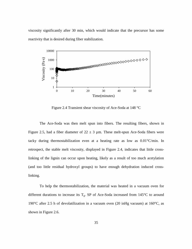
35
viscosity significantly after 30 min, which would indicate that the precursor has some
reactivity that is desired during fiber stabilization.
Figure 2.4 Transient shear viscosity of Ace-Soda at 148 °C
The Ace-Soda was then melt spun into fibers. The resulting fibers, shown in
Figure 2.5, had a fiber diameter of 22 ± 3 µm. These melt-spun Ace-Soda fibers were
tacky during thermostabilization even at a heating rate as low as 0.01°C/min. In
retrospect, the stable melt viscosity, displayed in Figure 2.4, indicates that little cross-
linking of the lignin can occur upon heating, likely as a result of too much acetylation
(and too little residual hydroxyl groups) to have enough dehydration induced cross-
linking.
To help the thermostabilization, the material was heated in a vacuum oven for
different durations to increase its Tg. SP of Ace-Soda increased from 145°C to around
190°C after 2.5 h of devolatilization in a vacuum oven (20 inHg vacuum) at 160°C, as
shown in Figure 2.6.
1
10
100
1000
10000
0 10 20 30 40 50 60
Vis
cosi
ty (
Pa·
s)
Time(minutes)

36
Figure 2.5 As-spun fibers of Ace-Soda
Figure 2.6 SP change with devolatilization time for Ace-Soda
100
120
140
160
180
200
220
0 1 2 3
Soft
enin
g p
oin
t (º
c)
Devolatilization Time (h)

37
The transient viscosity curve of Ace-Soda after different time periods of
devolatilization is shown in Figure 2.7. The results indicate long periods over which a
constant viscosity was observed, allowing for a significant duration available processing.
This was followed by a significant rise in viscosity, indicating decreased
thermostabilization with increased devolatilization time. However, fibers spun using the
highest SP (191°C) material still could not be cross-linked even with an extremely low
heating rate. The fibers could not be maintained in their glassy state and became tacky at
around 150°C. Once the precursor becomes tacky, it is not possible to retain individual
precursor fibers. This is likely due to the lower concentration of hydroxyl groups on soda
lignin after acetylation. Substitution of hydroxyl groups by the stable acetyl groups
prevented any significant cross-linking and thermal stabilization of the macromolecules
within the precursor fibers. We emphasize that molecular cross-linking within precursor
fibers is an essential step in transforming the fiber into a thermoset before it can be
carbonized. This confirms that the composition is not suitable for producing high-
performance carbon fibers.
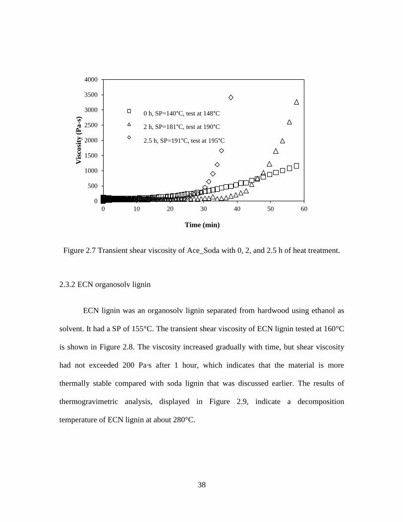
38
Figure 2.7 Transient shear viscosity of Ace_Soda with 0, 2, and 2.5 h of heat treatment.
2.3.2 ECN organosolv lignin
ECN lignin was an organosolv lignin separated from hardwood using ethanol as
solvent. It had a SP of 155°C. The transient shear viscosity of ECN lignin tested at 160°C
is shown in Figure 2.8. The viscosity increased gradually with time, but shear viscosity
had not exceeded 200 Pa·s after 1 hour, which indicates that the material is more
thermally stable compared with soda lignin that was discussed earlier. The results of
thermogravimetric analysis, displayed in Figure 2.9, indicate a decomposition
temperature of ECN lignin at about 280°C.
0
500
1000
1500
2000
2500
3000
3500
4000
0 10 20 30 40 50 60
Vis
co
sity
(P
a-s
)
Time (min)
0 hr, SP=140 c, test @148 C
2 hr, SP=181 C, test @ 190 C
2.5 hr, SP=191 C, test @ 195 C
0 h, SP=140°C, test at 148°C
2 h, SP=181°C, test at 190°C
2.5 h, SP=191°C, test at 195°C

39
Figure 2.8 Transient shear viscosity of ECN lignin at 1 and 3 s-1
, 160°C.
Figure 2.9 Thermogravimetric analysis of ECN lignin
0
0.5
1
1.5
2
2.5
3
3.5
0
50
100
150
200
250
0 10 20 30 40 50 60
Sh
ear
rate
(1
/s)
Vis
co
sity
(P
a·s
)
Time (min)
Viscosity
Shear rate
0
20
40
60
80
100
120
0 100 200 300 400 500 600 700
Wei
gh
t (%
)
Temperature (°C)

40
Melt spinning of ECN lignin was performed at 160°C. The resulting fibers were
uniform and circular with an average diameter of 29.3 ± 1.1 µm, as displayed in Figure
2.10.
Figure 2.10 ECN lignin fibers as seen on the take-up wheel (left) and as observed by light
microscopy in the transmission mode (right)
The initial stabilization trial was performed at a heating rate of 0.1°C/min. Fiber
became tacky at around 125°C. The second stabilization trial was performed carefully
with a relatively long procedure; the temperature profile is shown in Figure 2.11. The
fiber survived during stabilization, and the final oxidation temperature was 240°C. It took
more than 200 h (over 1 week) to stabilize the fibers to prevent fibers from being tacky.
This duration is much longer than that needed for most commercial PAN precursor fibers
that require about 2 h. The slow oxidation rate was attributed to relatively low hydroxyl
content in hardwood organosolv lignin.

41
Figure 2.11 The temperature profile during thermal stabilization of ECN lignin fiber
The average fiber size after oxidation reduced to 23.5 ± 0.5 µm due to the weight
loss during thermal oxidation. After stabilization, the ECN lignin fiber became infusible.
The stabilized fibers did not dissolve in acetone, indicating their cross-linked structure
after thermo-oxidation.
The stabilized fibers were carbonized at 1000°C. The resulting carbon fibers were
nominally 14 ± 1 µm in diameter, as shown in Figure 2.12. The SEM images show that
the carbon fibers had smooth surfaces and circular cross sections. The carbonized ECN
fibers displayed a tensile modulus, strength, and strain-to-failure values of 32 ± 4 GPa,
450 ± 130 MPa, and 1.4 ± 0.4%, respectively. The electrical resistivity of these fibers was
0
50
100
150
200
250
300
0 48 96 144 192 240 288
T (°C
)
Time (Hour)

42
about 60 µ-m. Although the tensile properties are not high enough for structural
applications, the electrical resistivity is similar to that of rayon-based fibers. Rayon is no
longer produced in the United States because of the hazards and environmental
regulations in its manufacturing. Rayon-based carbon fibers are used in missile casings
where lightweight and low-thermal conductivity is desired. Such ECN-based carbon
fibers may serve as a substitute, but the drawback of this ECN process is the extremely
slow stabilization step.
Figure 2.12 SEM micrographs of carbon fibers derived from ECN lignin
2.3.3 SKL lignin
As-received SKL showed no melting behavior during the entire heating procedure
even when the temperature reached 300°C at the end of the SP test. Instead, degradation
was observed, and the residue was a foamed state indicating the generation of volatiles
during heating. Above results are in agreement with those reported in previous literature

43
studies in which softwood lignin has been shown to possess poor thermal mobility
because it has higher cross-linked structure than does hardwood lignin (65). The hydroxyl
groups result in dehydration reaction between molecules. Thus, SKL cannot be melt-spun
without appropriate modification.
To achieve melt processability, acetylation of SKL was attempted. SKL was
reacted with acetic anhydride for 2 h to convert the hydroxyl groups into acetyl groups
using a reaction solution of 15 ml of acetic anhydride per gram of SKL. The resulting
acetylated softwood kraft lignin, referred to as “Ace-SKL”, showed a softening
temperature between 156 and 167°C. However, the viscosity of molten Ace-SKL at
170°C increased from about 80 Pa·s to 8,000 Pa·s within 30 min as shown in Figure 2.13
(a). The test finally ended due to overloading of the torque transducer. During heating,
several types of reactions can occur including dehydration, condensation, and addition
that induce an increase of molecular weight. Consequently, the viscosity increases
significantly and causes the failure of rheology test.
Ace-SKL was extracted with 75% acetic acid, and a fraction with relatively large
molecular weight was removed. A similar study has been reported by Saito et al. (16)
using methanol to obtain a hardwood lignin fraction with a much lower molecular weight,
which displayed a SP. After extraction, the fraction soluble in 75% acetic acid in the
current study had a SP between 136- 145°C. The viscosity remained below 500 Pa·s for
the first 30 min at 145°C, as shown in Figure 2.13 (b), as a result of the lower molecular
weight. This indicates that subsequent melt spinning may proceed as a stable process.

44
Figure 2.13 Transient shear viscosity of (a) Ace-SKL and (b) 75% acetic acid extracted
Ace-SKL
The extracted Ace-SKL was melt-spun into fibers, as illustrated in Figure 2.14 (a).
Although the extracted Ace-SKL was easy to spin into fibers, it was virtually impossible
to stabilize them by thermo-oxidative stabilization. Similar to Ace-Soda lignin,
substitution of hydroxyl groups by the stable acetyl groups prevented any significant
crosslinking and thermal stabilization of the macromolecules within the precursor fibers.
Although an extremely slow ramp heating rate of 0.01°C/min was applied, the fibers
could not be maintained in their glassy state and became tacky at around 150°C, as
shown in Figure 2.14 (b). Therefore, this composition is not well-suited for producing
carbon fibers due to the difficulty in its stabilization.
1
10
100
1000
10000
0 10 20 30 40 50 60
Vis
cosi
ty [
Pa
·s]
Time [min]
(a) Ace_SKL
(b) 75% Acetic acid extracted Ace_SKL
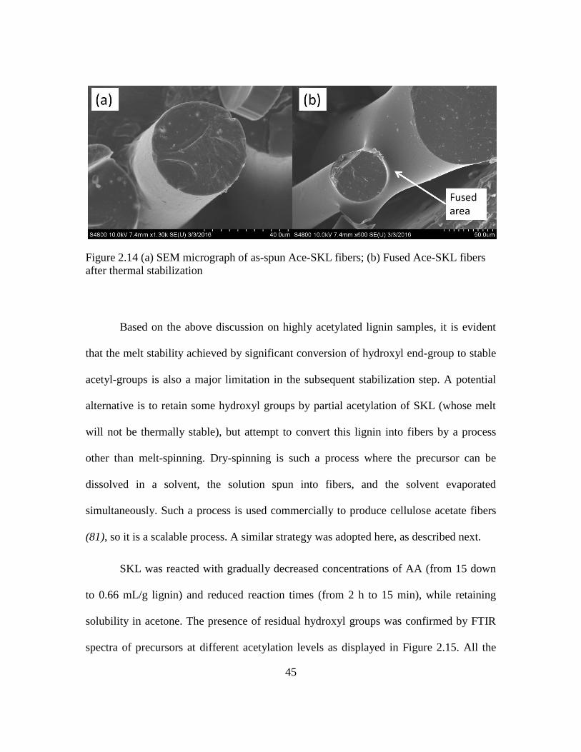
45
Figure 2.14 (a) SEM micrograph of as-spun Ace-SKL fibers; (b) Fused Ace-SKL fibers
after thermal stabilization
Based on the above discussion on highly acetylated lignin samples, it is evident
that the melt stability achieved by significant conversion of hydroxyl end-group to stable
acetyl-groups is also a major limitation in the subsequent stabilization step. A potential
alternative is to retain some hydroxyl groups by partial acetylation of SKL (whose melt
will not be thermally stable), but attempt to convert this lignin into fibers by a process
other than melt-spinning. Dry-spinning is such a process where the precursor can be
dissolved in a solvent, the solution spun into fibers, and the solvent evaporated
simultaneously. Such a process is used commercially to produce cellulose acetate fibers
(81), so it is a scalable process. A similar strategy was adopted here, as described next.
SKL was reacted with gradually decreased concentrations of AA (from 15 down
to 0.66 mL/g lignin) and reduced reaction times (from 2 h to 15 min), while retaining
solubility in acetone. The presence of residual hydroxyl groups was confirmed by FTIR
spectra of precursors at different acetylation levels as displayed in Figure 2.15. All the

46
spectra were normalized with respect to the peaks at 856 cm-1
, which is attributed to C-H
bending on aromatic rings. As the amount of acetic anhydride decreased from 15 ml to
0.66 ml per gram of lignin, intensity of the hydroxyl peak at 3400 cm-1
increased
significantly. Also, the weight gain of lignin after reaction moderated from 18% to 5%.
Figure 2.15 FTIR spectra of SKL at different acetylation levels
Softening point was also measured for Ace-SKL with different reaction
composition. As displayed in Figure 2.16, as the extent of acetylation decreased, resulting
material had elevated SPs exceeding 200°C, which is favorable for subsequent thermo-
oxidative stabilization. 0.66 ml AA/gram lignin was found to be a practical low limit.
This grade was miscible in an acetone and could be formed into a viscous solution that
0
0.2
0.4
0.6
0.8
1
1.2
1.4
1.6
400900140019002400290034003900
Abso
rpti
on
Wavenumber [cm-1]
1g/0.66 ml, 15 min reaction
1g/1 ml, 15 min reaction
1g/1.5 ml, 15 min reaction
1g/2ml, 15 min reaction
1g/15 ml, 2 hr reaction

47
could be manually drawn into filaments and acetone evaporated rapidly. Glass transition
temperature, as estimated using DSC, is displayed in Figure 2.17. Tg of Ace-SKL reacted
from 1.5-15 ml acetic anhydride per gram SKL were all between 90-105°C, but was
noticeably higher at 112°C for Ace-SKL obtained using 0.66 ml acetic anhydride per
gram of SKL. The increase of Tg was attributed to stronger intermolecular hydroxyl
group interactions, i.e., when less hydroxyl groups were reacted away with acetic
anhydride. The presence of such interactions is favorable for the following thermo-
oxidative stabilization reactions.
Figure 2.16 Softening points of Ace-SKL with different reaction composition
140
150
160
170
180
190
200
210
0 2 4 6 8 10 12 14 16
So
ften
ing p
oin
t (°
C)
Acetic anhyride concentration (ml / g SKL)
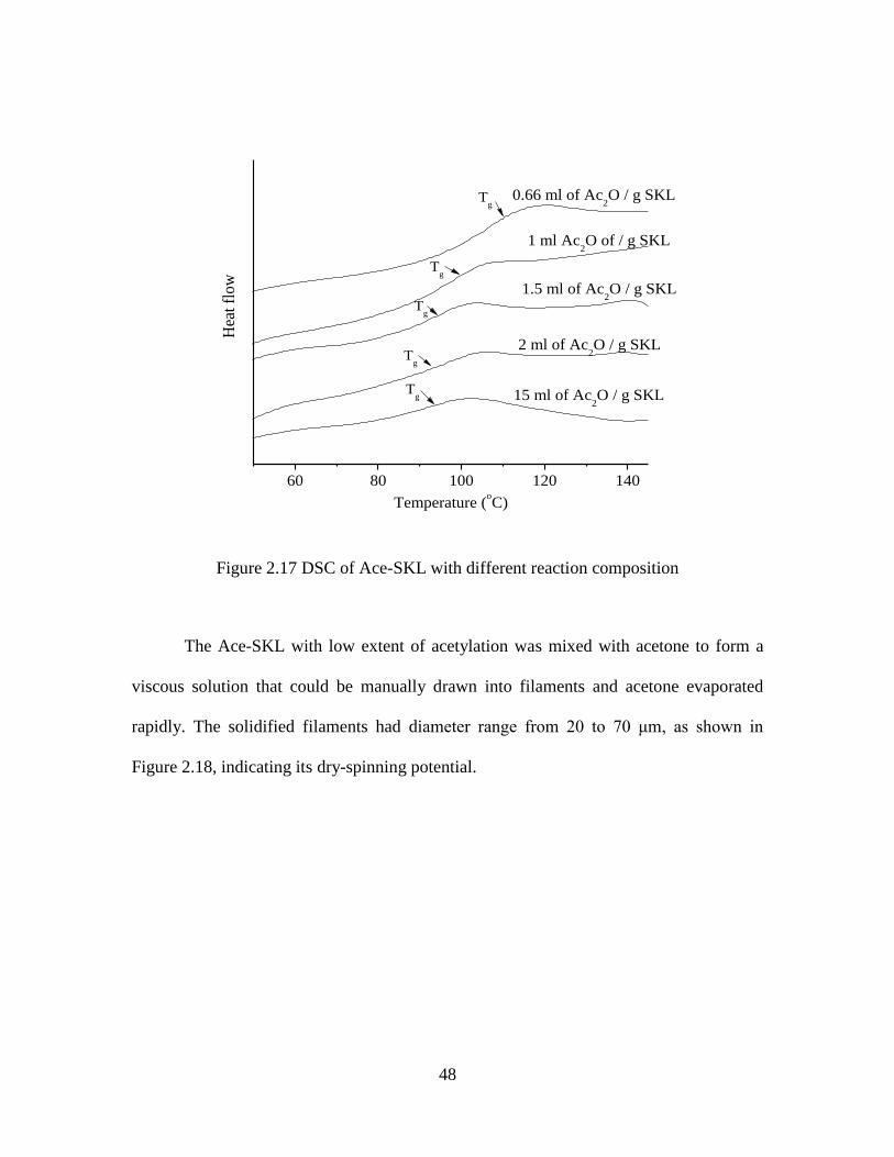
48
60 80 100 120 140
Tg
Tg
Tg
Tg
15 ml of Ac2O / g SKL
2 ml of Ac2O / g SKL
1.5 ml of Ac2O / g SKL
1 ml Ac2O of / g SKL
Hea
t fl
ow
Temperature (oC)
0.66 ml of Ac2O / g SKLT
g
Figure 2.17 DSC of Ace-SKL with different reaction composition
The Ace-SKL with low extent of acetylation was mixed with acetone to form a
viscous solution that could be manually drawn into filaments and acetone evaporated
rapidly. The solidified filaments had diameter range from 20 to 70 μm, as shown in
Figure 2.18, indicating its dry-spinning potential.

49
Figure 2.18 Ace_SKL filaments manually drawn from acetone solution
Thermo-oxidation was attempted to stabilize the filaments. The following general
heating procedure was used to thermo-oxidatively stabilize the fiber: heating from 70 to
140°C, at a heating rate of 0.4°C/min; holding at 140°C for 10 h; heating from 140 to
220°C, at a heating rate of 0.1°C/min with holding time of 3 hours at intermediate
temperatures of 150, 160, 170, 180, and 220°C. Larger content of hydroxyl group
increased the reactivity and enabled crosslinking during thermo-oxidation, and filament
shape was preserved without fibers becoming tacky. The stabilized filaments heated to
1000°C. The interesting observation is that the filament survived the carbonization step
and led to the initial production of carbon fibers from dry-spun precursor fibers.
50
2.4 Conclusions
In the initial phase of this research study, three types of lignins (soda lignin,
organosolv lignin and softwood kraft lignin) were investigated as precursors for
converting into carbon fibers, as summarized in Table 2.1. Without suitable modification,
soda lignin and SKL could not be melt spun due to the existence of large molecules or a
large content of hydroxyl groups, which could lead to dehydration reaction. ECN lignin
could be converted into carbon fiber, but required impractically slow heating rate during
stabilization. Acetylation and fractionation was performed on soda lignin and SKL, and
the resulting materials possessed relatively stable melt viscosity and were capable of
being melt-spun. However, high extent of substitution of hydroxyl groups into thermally
stable acetyl group prevented the subsequent thermal stabilization. SKL with limited
acetylation was found to have the potential of being solution spun and successfully
thermo-oxidatively stabilized and carbonized. This Ace-SKL with limited extent of
acetylation was systematically investigated. The flowing chapters present the rheology
and dry-spinning (Chapter Three), carbonization and properties of carbon fibers (Chapter
Four), and dual UV-thermal stabilization route (Chapter Five) for rapid stabilization.

51
Table 2.1 Carbon fiber potential of lignin and modified lignin precursors
Lignin Type SP Spinning
Potential
Stabilization
Potential
Carbon Fiber
Potential?
Soda lignin
As-received 245°C Not melt
spinnable N/A X
Acetylated
(Ace-Soda) 145°C
Melt
spinnable
Not able to
cross-link X
ECN
organosolv
lignin
As-received 155°C Melt
spinnable
Very slow
stabilization
procedure
√ converted to
carbon fibers
Softwood
Kraft
Lignin
(SKL)
As-received No
SP
Not melt
spinnable N/A X
Ace-SKL
(high extent of
substitution
followed by
fractionation)
136-
167°C
Melt
spinnable
Not able to
cross-link X
Ace_SKL
(low extent of
substitution)
205°C
Not melt
spinnable,
can be
solution spun
Can be thermo-
oxidative
stabilized
√ converted to
carbon fibers

52
CHAPTER THREE
EFFECT OF TEMPERATURE AND CONCENTRATION ON FLOW
CHARACTERISTICS OF ACETYLATED-LIGNIN SOLUTIONS
3.1 Introduction
This chapter discusses the rheology of lignin solutions and processing of these
solutions into precursor fibers by dry-spinning. In the previous chapter (Section 2.3.3),
partial acetylation of softwood kraft lignin (SKL) was discussed as a strategy to preserve
a fraction of hydroxyl groups. The partially acetylated lignin could be dissolved into
acetone and formed into thin filaments, and the resulting material could be successfully
stabilized and carbonized. These results indicated the potential of dry-spinning using this
partially acetylated Ace-SKL. Whereby, lignin fibers solidify in air while acetone
evaporates rapidly. Acetone is a benign solvent that can be recovered, condensed and
recycled, and is used in scalable industrial processes such as those used to produce
cellulose acetate fibers (81).
To determine the dry-spinning potential of Ace-SKL, the flow characteristics and
mass-transfer issues associated with Ace-SKL/acetone solutions need to be studied, since
they play an important role during fiber spinning, including evaporation of solvent, to
form solid filaments. Therefore, the goal of the study reported in this chapter was to
investigate Ace-SKL/acetone solutions to establish a range of suitable combinations of
solution concentrations and spinning temperatures. Thus, dry-spinning was conducted
under various conditions to determine their effect on the morphology of the resulting
lignin precursor fibers.

53
3.2 Experimental
3.2.1 Materials
As described earlier in Section 2.3.3, softwood Kraft lignin, IndulinAT
(SKL), was
used throughout this study. The commercial availability of this raw material from Mead-
Westvaco, Charleston, SC, indicates its potential in conversion to carbon fibers by an
industrially scalable process.
However, for use as a carbon precursor, SKL lignin had to be purified because its
ash content was 2.85%, which is too high to produce carbon fibers without defects. The
non-carbon content of such precursors can play a significant role in creating defects in the
resulting carbon fibers. Thus, before acetylation, washing was performed on SKL lignin
to reduce the ash content. Different combinations of mixing time, liquid to solid ratio,
and washing solution pH value were studied to determine a suitable protocol for washing.
SKL was washed with acidified DI water under different conditions, and ash
contents thus obtained are listed in Table 3.1. The results indicate that larger liquid-to-
solid ratio, pH value of 2, and mixing time of 15 min is favorable to efficiently reduce the
ash content. When this cycle was repeated, it was also found that using 10 ml acidified DI
water (pH=2) per gram of SKL and 15 min of mixing time for each wash resulted in ash
content of around 0.15% after 25 cycles. After 5 more washes, there was no substantial
reduction of ash content. Thus, 10 ml acidified DI water (pH=2) per gram of SKL, 15
min of mixing time, and 25 washing cycles were established as the standard protocol for
each batch of SKL purification. After washing under above conditions, the ash content

54
was reduced to 0.15%, and a comparison of main metal impurities before and after
washing is listed in Table 3.2.
Table 3.1 Ash content resulting after different washing conditions
ml liquid/gram of SKL pH Mixing time
(min) Ash%
5 2 30 1.73
12.5 2 30 1.56
30 2 30 1.29
60 2 30 1.09
30 2 3 1.59
30 2 15 1.30
30 2 30 1.29
30 1 30 1.33
30 2 30 1.29
30 4 30 1.98
Table 3.2 Elemental analysis result of SKL before and after wash
K Ca Mg Fe S Na Al Si
wt.% wt.% wt.% wt.% wt.% wt.% wt.% wt.%
SKL 0.105 0.014 0.017 0.005 1.219 0.753 0.015 0.023
Washed SKL 0.003 0.008 0.012 0.004 0.684 0.007 0.014 0.018
Starting with the purified SKL, limited acetylation was conducted. Details of the
modification process were discussed earlier in Sections 2.2.2 and 2.3.3. Thirty grams of

55
purified SKL was mixed with 20 mL acetic anhydride in a round-bottomed flask. The
flask was connected with a reflux condenser and dipped into a water bath set at 85-90°C
with continuous stirring. In the initial stage of mixing, manual stirring was necessary to
wet the dry lignin powders. The mixture was reacted for 15 min. The partially acetylated
SKL (Ace-SKL) was capable of crosslinking during thermal oxidation.
Ace-SKL/acetone solution was prepared by mixing 50 g of Ace-SKL dry powder
with 100 ml acetone. The mixture was manually stirred and solvent evaporated until
solution was concentrated to above 1.7 g solids/mL acetone. Also, the concentrated
solutions were put into ultrasonic tank to achieve homogeneity. To measure the
concentration of various solutions, the solutions were weighed precisely, vacuum dried at
95°C for 2 hours, and re-weighed.
3.2.2 Rheology and spinning
The viscosity of Ace-SKL solutions at various concentrations and temperatures
was measured using an ACER 2000 capillary rheometer (Rheometric Scientific). High
shear measurements were conducted at shear rates ranging from 3,000 to 10,000 s-1
. In an
attempt to measure more fundamental rheological properties of the Ace-SKL solutions,
tests were also conducted at low shear rates using a cone-plate fixture. Unfortunately, the
rapid evaporation of acetone from edges led to inaccurate and unrepeatable results.
Therefore, only the high shear results obtained reliably from capillary rheometer are
discussed, as these are also of greater relevance for the extrusion step during fiber
spinning. Capillaries of 1 mm diameter and three L/D ratios (5, 15, and 25) were used to
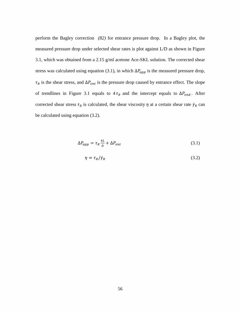
56
perform the Bagley correction (82) for entrance pressure drop. In a Bagley plot, the
measured pressure drop under selected shear rates is plot against L/D as shown in Figure
3.1, which was obtained from a 2.15 g/ml acetone Ace-SKL solution. The corrected shear
stress was calculated using equation (3.1), in which ∆𝑃𝑎𝑝𝑝 is the measured pressure drop,
𝜏𝑅 is the shear stress, and ∆𝑃𝑒𝑛𝑡 is the pressure drop caused by entrance effect. The slope
of trendlines in Figure 3.1 equals to 4 𝜏𝑅 and the intercept equals to ∆𝑃𝑒𝑛𝑑 . After
corrected shear stress 𝜏𝑅 is calculated, the shear viscosity 𝜂 at a certain shear rate ��𝑅 can
be calculated using equation (3.2).
∆𝑃𝑎𝑝𝑝 = 𝜏𝑅4𝐿
𝐷+ ∆𝑃𝑒𝑛𝑡 (3.1)
𝜂 = 𝜏𝑅/��𝑅 (3.2)
57
Figure 3.1 Bagley plot of 2.15 g/ml Ace-SKL solution
Dry-spinning was performed using a batch unit custom-designed by AJA Inc.
(Greenville, SC). The viscous solution was transferred into a spinning barrel fitted with a
4-hole die, with each hole having a diameter of 75 μm and a length of 225 μm. The
spinning barrel had a diameter of 18 mm. In this lab-scale process, the solvent was vented,
but in a commercial process, the solvent can be condensed and recycled.
The Ace-SKL / acetone solutions could be drawn into filaments when the
concentration exceeds 1.7 g solids/mL acetone. Thus, Ace-SKL / acetone solutions were
prepared at three concentrations: 1.85, 2.00, and 2.15 g solids/mL acetone. These
solutions were dry-spun at temperatures ranging from ambient (25°C) to 52°C. During
0
4
8
12
16
20
0 10 20 30 40
ΔP
ap
p (
MP
a)
L/D
10000 s⁻¹
6000 s⁻¹
3000 s⁻¹

58
spinning, the draw-down ratio (DDR) was controlled between 5.7-6.9 at a nominal roll
speed of 130 m/min.
Scanning electron microscopy (SEM, Hitachi S4800) was used to analyze the
cross-section shape and dimension. The perimeter and area of single fibers were
measured using Quartz PCI software and “Freenhand shape measuring tool”. For each
group of as-spun fibers, 10 fiber samples were measured to obtain the average cross-
sectional area and perimeter, as well as other features of fiber shape.
3.3 Results and Discussion
3.3.1 Viscosity and flow characteristics
After purification, the SKL with an ash content of about 0.15% was modified by
acetylation, as described earlier in Chapter Two. Ace-SKL/acetone solutions were
prepared for dry-spinning. In typical commercial fiber spinning equipment, pressure drop
across spinnerets must be limited to about 14 MPa (2,000 psi). In preliminary
experiments, it was found that the pressure drop across the spinneret was excessive even
at the lowest concentration (1.85 g/mL) when the experiment was conducted at ambient
temperature (25°C). Therefore, flow characteristics were needed at elevated temperatures
to determine the extent of viscosity reduction and resulting pressure drop.
Figure 3.2 (a) displays the viscosity of the three solutions at ambient and elevated
temperatures. For these results, entrance pressure drop was subtracted using Bagley
correction method (82). Results show clearly that Ace-SKL / acetone solutions are shear-
59
thinning at all temperatures and concentrations investigated. As expected, viscosity
increased as Ace-SKL concentration increased (ambient temperature = solid symbols).
Also, viscosity of all three solutions could be reduced significantly by increasing the
temperature (open symbols). The extent of temperature increase was higher for the most
concentrated solution.
The viscosity curves were fitted to a power-law model. It should be noted that for
a Newtonian fluid the power law exponent (n) equals 1, whereas for polymeric solutions
n < 1. For Ace-SKL solutions at various concentrations and temperatures, the power-law
exponent was found to range from 0.33 to 0.82, which confirms the macromolecular
nature of the Ace-SKL lignin precursor.
The power-law parameters were also used to predict pressure drops (∆P) expected
in the spinnerets using the following equation for a power-law fluid (83):
Q = (πR3
1/n + 3)(
R∆P
2mL)1/n
(
(3.3)
where Q is the flow rate, R is the capillary diameter, L is the capillary length, m
and n are the power law parameters. Calculations were performed using power-law
parameters obtained for the three combinations: 1.85 g/mL at 35°C, 2.00 g/mL at 40°C,
and 2.15 g/mL at 50°C. For the three concentrations, (1.85, 2.0 and 2.15 g/mL), the
predicted ∆P were 4.1 MPa (590 psi), 3.4 MPa (490 psi), and 3.4 MPa (500 psi). Because
these predicted ∆P values do not include end-effects, viscosity results from the short L/D

60
= 5 capillary [Figure 3.2 (b)] were also used. The predicted values were 12.0 MPa (1740
psi), 11.8 MPa (1710 psi) and 11.5 MPa (1670 psi), which are fairly consistent with the
measured values of 10.1 MPa (1460 psi), 10.0 MPa (1450 psi) and 8.4 MPa (1220 psi)
during the fiber spinning experiments, discussed next.
Figure 3.2 Shear viscosity of Ace-SKL solutions over a range of shear rates. (a) Viscosity
obtained after Bagley correction using capillaries with L/D = 5, 15 and 20; (b) Viscosity
obtained from capillaries with L/D = 5, without Bagley correction.
3.3.2 Fiber spinning
Figure 3.3 displays SEM images of lignin fibers obtained from a 1.85 g/mL
solution. Continuous filaments could be drawn consistently at a roll-speed of 130 m/min
10
100
1000
2000
Vis
cosi
ty (
Pa
·s)
Shear rate (s-1)
2.15 g/ml acetone, 25°C
2.00 g/ml acetone, 25°C
1.85 g/ml acetone, 25°C
2.15 g/ml acetone, 50°C
2.00 g/ml acetone, 40°C
1.85 g/ml acetone, 35°C
10000
(a)
2000
Shear rate (s-1)
2.15 g/ml acetone, 25°C
2.00 g/ml acetone, 25°C
1.85 g/ml acetone, 25°C
2.15 g/ml acetone, 50°C
2.00 g/ml acetone, 40°C
1.85 g/ml acetone, 35°C
10000
(b)

61
and spinning temperatures of approximately 30°C from this lowest concentration solution.
It is noted that the as-spun fiber diameters were quite fine, about 30 to 40 μm. In Chapter
Four, the post-stretching and stabilization of these lignin fibers will be discussed.
Subsequently, such lignin-based precursor fibers can be successfully carbonized. Another
interesting feature of the dry-spun lignin-based precursor fibers, as well as the resulting
carbon fibers, is their crenulated shape. When used in polymeric composites, the
crenulated shape can enhance the interfacial bonding between carbon fibers and resin by
providing increased contact area, and is a desirable feature. Therefore, these
characteristics were studied further.
As displayed in Figure 3.3 (also at a concentration of 1.85 g/mL), as the spinning
temperature increases, fibers developed more crenulations. Also, some crenulations
became doubly convex crevices, such as that identified by the encircled region in the
SEM images displayed in Figure 3.3. A SEM image of a crevice at higher magnification
is shown in Figure 3.4. Such sharp crevices are not desired as these would be difficult to
infuse with polymeric resins and result in inadequate fiber-surface wetting if such carbon
fibers were converted into composites. Therefore, other dry-spinning conditions were
investigated next.

62
Figure 3.3 SEM images of Ace-SKL lignin fibers from a 1.85 g/mL solution, at various
spinning temperatures.

63
Figure 3.4 Magnified SEM image of a sharp crevice on the surface of as-spun lignin fiber
obtained from 1.85 g/mL solution.
Figure 3.5 displays the SEM images from a more concentrated solution, 2.00
g/mL. Higher spinning temperature was required to achieve lower viscosity and better
processability. Stable filament winding could be achieved for spinning temperatures of
about 35°C and higher. Again, the crevices started to show up when spinning temperature
was above 40°C. The sharp notches on the surface of some fibers fused together at the
outer edge, leaving a hollow space/void.
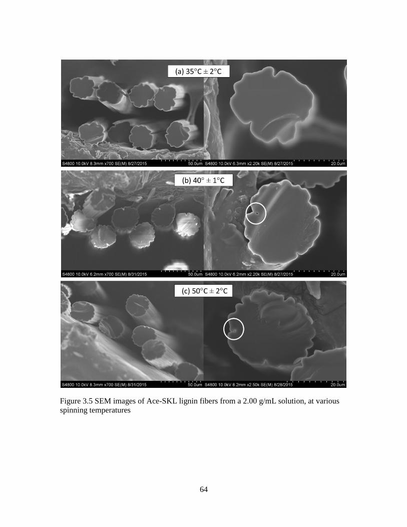
64
Figure 3.5 SEM images of Ace-SKL lignin fibers from a 2.00 g/mL solution, at various
spinning temperatures

65
The highest concentration of solution used in this study was 2.15 g/mL, and
Figure 3.6 displays SEM micrographs of fibers obtained from this solution. Fibers could
be continuously spun when solution temperature approached 40°C. Due to a lower
fraction of solvent in this concentrated solution, a smaller volume reduction resulted in
fibers during the drying step. Consequently, the collapse of fiber surface during diffusion
was not as significant as for the more dilute concentrations. Thus, fibers produced from
this concentrated solution did not possess sharp crevices at any of the spinning
temperatures. Clearly, 2.15 g lignin/mL solvent is a suitable concentration for the given
Ace-SKL to produce fibers with the desired morphology. These results establish the
importance of precursor solution concentration in determining the shape and features of
the resulting lignin fibers.

66
Figure 3.6 Ace-SKL lignin fibers from dry-spinning of 2.15 g/mL solution at various
spinning temperatures.
A quantitative analysis of fiber microstructure is listed in Table 3.3. The average
number of crenulations on each fiber (CN) are reported because the exact number varies
from fiber to fiber. Another measure of the surface undulation is the ratio of the enhanced
lateral surface area of the crenulated fibers compared with circular fibers possessing
equal cross-sectional area, which is reported in Table 3.3 as SR. This represents the
enhancement of fiber-matrix surface area due to crenulations for a given volume fraction
of the reinforcing fibers in a composite material. For all concentrations, current results

67
confirm that fibers spun at a higher temperature had a larger number of crenulations,
which facilitates rapid out-diffusion of solvent. As discussed previously, higher spinning
temperatures also helped reduce the solution viscosity and resulting pressure drop within
spinnerets.
Table 3.3 Fiber surface characteristics of Ace-SKL as-spun fibers at various
concentrations and appropriate processing temperatures. CN is the average number of
crenulations on each fiber, and SR is the ratio of the enhanced surface area of the
crenulated fibers compared with circular fibers possessing equal cross-sectional area.
Temperature 35°C ± 2°C 40°C ± 1°C 50°C ± 2°C
1.85
g/mL
CN (Average number of
crenulations per fiber) 15.1 ± 0.4 19.1 ± 1.2 24.6 ± 0.8
SR (%) (Enhancement of
lateral surface area) 135.1 % ± 1.2% 134.2% ± 1.9% 132.4% ± 0.9%
2.00
g/mL
CN (Average number of
crenulations per fiber) 11.8 ± 0.6 16.1 ± 0.4 19.4 ± 0.5
SR (%) (Enhancement of
lateral surface area) 131.2% ± 1.2% 133.5% ± 1.4% 136.4% ± 1.1%
2.15
g/mL
CN (Average number of
crenulations per fiber) Too viscous 13.6 ± 0.4 17.3 ± 0.1
SR (%) (Enhancement of
lateral surface area) Too viscous 127.1% ± 1.5% 136.5% ± 1.7%
Dry-spinning is a complex process that includes three simultaneous phenomena:
non-Newtonian fluid flow (fiber extrusion and draw-down), heat-transfer (fiber cooling),
and mass transfer (solvent evaporation). So, exact mathematical modeling is beyond the

68
scope of this work, but the development of crenulations can be explained semi-
quantitatively as follows.
During evaporation of acetone through the circular (nominal) fiber, the radial
mass flux
nAr scales with the concentration gradient:
nAr ~ DAB
∂ωA
∂r
(
(3.4)
where DAB is the mass diffusivity of acetone in the solution, and ωA is the weight
fraction of acetone. As the solvent diffuses out, the volume of the fiber decreases and so
does its surface area, which for a circular cross-section would lead to a decrease in
overall evaporation rate (mass/time). However, to facilitate the overall mass-transfer rate,
the fiber cross-section changes from smooth (circular) to crenulated, which increases the
specific area. As demonstrated in Table 3.3, crenulated fibers possess about 35% more
external specific surface area compared with circular fibers with the same cross-sectional
area (SR).
For carbon fibers, it is known that smooth circular cross-section leads to better
strength than the ones containing sharp crevices such as that observed in the MP-based
CFs that possess a “pac-man” split (84). For dry-spun Ace-SKL precursor fibers, it is not
possible to obtain circular fibers because the finite rate of out-diffusion of solvent (at any
temperature or solvent concentration) still produces a wavy surface. In an attempt to

69
produce fibers with smooth surface and shapes close to circular from dry-spinning, a 2.15
g/ml solution was dry-spun at room temperature for slower diffusion of acetone. The
spinning was extremely difficult and the process had to stop due to plugging of spinneret
hole as the pressure drop approached the high alarm value of 24 MPa (3,500 psi). The
limited fibers that were collected are illustrated in Figure 3.7 (a). Although the as-spun
fibers displayed a ribbon-like shape and smooth surface, the extrudate could not be
drawn-down to fine fiber diameters below about 30 µm that are highly desired for
producing high strength carbon fibers.
To enable dry-spinning at room temperature (25°C), a solution at a lower lignin
concentration of 2.00 g/ml was prepared. The spinning was still difficult due to a high
pressure drop of 2700 psi within the spinneret. The as-spun fibers, shown in Figure 3.7
(b), displayed a relatively smooth lateral surface but noncircular cross-section.
The crenulated pattern from dry-spinning at elevated temperatures was preserved
in the carbonized fibers, and the carbonization of these precursor fibers and properties of
the resulting carbon fibers are discussed next in Chapter Four.

70
Figure 3.7 As-spun fibers from dry-spinning of Ace-SKL/acetone solutions at room
temperature at two different concentrations: (a) 2.15 g/ml and (b) 2.00 g/ml
3.4 Conclusions
Shear viscosity of Ace-SKL solutions displayed a significant shear-thinning
behavior at all temperatures studied. The viscosity results could be modeled with power-
law exponents ranging from 0.33 to 0.82, confirming the macromolecular nature of the
Ace-SKL lignin/acetone solutions. As expected, elevated temperatures lead to lower
viscosities and facilitate extrusion at pressures under 10 MPa (about 1500 psi). As-spun
fibers produced from dilute solutions (1.85 and 2.00 g/mL) developed some sharp
crevices on the fiber surface. These are undesirable for subsequent processing of resulting
carbon fibers into composites by resin-infusion. For the most concentrated solution
investigated in this study, 2.15 g/mL, the resulting fibers contained no sharp crevice. All
fibers produced by the dry-spinning process led to crenulated fiber surface, with the

71
highest spinning temperature leading to most crenulations. Room temperature spinning
was also attempted for the purpose of obtaining fibers with circular cross-section, but
resulted in excessive pressure drop during dry-spinning that is not suited for scaled-up
processes. About 35% larger surface area could be achieved in Ace-SKL as-spun fibers
(as compared with equivalent circular fibers), indicating the potential of such biomass-
derived fibers in providing larger fiber/matrix bonding area when used in composites.

72
CHAPTER FOUR
CARBON FIBER DERIVED FROM ACE-SKL: HEAT TREATMENT AND CARBON
FIBER CHARACTERIZATION
4.1 Introduction
As discussed in Chapter One, production of carbon fibers is a complex process
that requires a series of steps. During the heat treatment step, tension must be applied to
the fibers to improve mechanical properties. Stretching is necessary during the
stabilization and carbonization of PAN precursors, and results in improvement of
modulus and strength of resulting carbon fiber due to the preserved molecular orientation
(85-87). Also, for the production of rayon based carbon fibers, stretching is a significant
protocol during carbonization to achieve orientation within the carbon fibers (32-34).
Only for mesophase pitch based carbon fibers, there is no need to apply tension during
stabilization and carbonization as the discotic pitch molecules align in the fiber axis
during melt spinning and cannot relax subsequently (2, 4).
Most of prior studies on lignin-based carbon fibers have focused on the fiber-
forming step by the modification of lignin precursors. Although different types of lignin
precursors have been explored to produce carbon fibers, the highest tensile strength
reported for those lignin-based carbon fibers was only 660 MPa (59, 62, 65, 66, 74, 88,
89). It is necessary to improve the conditions during the entire process of carbon fiber
production process to achieve better mechanical properties. An investigation of dry-
spinning conditions to obtain the derived microstructure was discussed in Chapter Three.

73
Stabilization and carbonization step will be discussed in this chapter, particularly with
attention to applied tension/stretching during heat treatment. The microstructure and
properties of resulting carbon fibers are finally discussed.
4.2 Experimental
4.2.1 Thermal stabilization
Ace-SKL as-spun fibers were obtained by the method discussed in Chapter Three.
To “stabilize” these fibers into a thermoset state, they were placed in a programmable air
oven. The heating cycle was: heating from 70 to 140°C at a heating rate of 0.4°C/min;
holding at 140°C for 10 h; heating from 140 to 150°C at a heating rate of 0.1°C/min;
holding at 150°C for 4 h; heating from 150 to 160°C at a heating rate of 0.1°C/min;
holding at 160°C for 4 h; heating from 160 to 170°C at a heating rate of 0.1°C/min;
holding at 170°C for 3 h; heating from 170 to 180°C at a heating rate of 0.1°C/min;
holding at 180°C for 3 h; heating from 180 to 220°C at a heating rate of 0.2°C/min;
holding at 220°C for 3 h.
Tension was applied during heat treatment. Ace-SKL precursor fibers were
mounted within graphite end-tabs at both ends using fast-cure epoxy. The mounting
procedure is illustrated in Figures 4.1 (a) and (b). In Figure 4.1 (a), a fiber tow with about
0.01-0.03 gram weight and 3-5 cm length was cut and weighed in balance. One end of the
aligned fiber tow was placed in the graphite end tab, with fast cure epoxy applied on the
tab. Another layer of graphite end tab was bonded beyond those fibers to form a
“sandwich” structure. The fiber tow, with one end glued, was weighed again and the

74
weight of the end tabs factored into load applied during stabilization. After the other side
was glued, the fiber tows were loaded in tension, as illustrated in Figure 4.1 (c).
Figure 4.1 Stabilization of Ace-SKL fiber tow under tension
4.2.2 Carbonization
After stabilization, the fiber tows were mounted again with graphite end tabs but
using a ceramic based glue Ceramabond 671 (Aremco Products Inc.) that could survive
the high carbonization temperature. As shown in Figure 4.2, ends of the stabilized fiber
(a) (b)
(c)

75
tows were fixed on a layer of graphite sheet with scotch tape. The tows were maintained
under slight tension to keep a good alignment of fibers. One piece of a new end tab for
carbonization was carefully inserted under the fiber tow, and Ceramabond 671 was
applied on top of the end tab. Another piece of end tab was glued on top of the fibers.
After two ends were glued with Ceramabond 671, the newly mounted tows were put into
oxidation oven at 94°C for two hours for curing of the adhesive.
Figure 4.2 Mounting of stabilized fiber tows with Ceramabond 671
End tab for
stabilization
End tab for carbonization
glued with Ceramabond
671
End tab inserted under
fiber tows

76
Then carbonization was performed under tension using a customized graphite
rack, as illustrated in Figure 4.3. Fiber tows were suspended on the rack, and appropriate
tungsten weights were loaded at the bottom using tungsten wires. The rack with fiber
tows was put into a cup made with graphite sheet. If the tows broke during carbonization,
the graphite cup could catch the dropped tungsten weight. Most of the Ace-SKL based
carbon fibers in this study were obtained from carbonization performed at 1000°C for 1 h,
with a ramp from room temperature to 1000°C of 3.5 h. Also, one batch of carbonized
fibers were further carbonized to 2400°C.
Figure 4.3 Carbonization of Ace-SKL fiber tow under tension using customized graphite
rack

77
4.2.3 Charaterization
To measure the density of Ace-SKL based carbon fibers, a series of density floats
was used to prepare cesium formate solutions with densities ranging from 1.50 to 2.25
g/cm3 in increments of 0.05 g/cm
3 (Figure 4.4). Ace-SKL derived carbon fibers were
immersed into these solutions and allowed to settle for 24 h. Based on the solution in
which the fibers sunk as opposed to the next denser solution where the fiber floated
enabled density measurements to within ± 0.025 g/cm3. For carbon fibers produced in this
study (1000°C), fibers floated on surface of solutions with density larger than 1.75 g/ml
and sank to the bottom of solutions with density lower than 1.70 g/ml. Thus, the density
of Ace-SKL carbon fibers could be bracketed between 1.70 and 1.75 g/cm3.
Figure 4.4 Cesium formate solution prepared with density floats

78
Raman spectra were recorded on a Renishaw System (Gloucestershire, UK) using
a near infrared 780 nm-diode laser. The Raman shift was calibrated with a silicon
standard centered at 520 cm-1
. Raman spectra were analyzed using WiRE software v3.2
to integrate the peaks.
Wide angle X-ray diffraction (WAXD) patterns were obtained from a Rigaku
CuKα X-ray source at wavelength of 0.15406 nm, with the X-ray source operated at 45
kV and 0.65 mA. Fiber bundles were mounted on a paper tab and sprinkled with NIST-
grade silicon standard powder for accurate identification of 2θ position on integrated
azimuthal scan. The exposure time per sample was 1 h. The spacing of (0 0 2) plane (d002)
were calculated according to Bragg’s law with the following equation (4.1):
𝑑002 =𝜆
2 sin 𝜃
(
(4.1)
where λ corresponds to the wavelength of the X-ray beam (0.15406 nm), and θ is
the angle of incidence of the X-ray beam. According to the model given by Maire and
Mering (102), degree of graphitization was calculated using the equation (4.2):
𝑔(%) =0.3440 − 𝑑002
0.3440 − 0.3354× 100
(
(4.2)
where g is the degree of graphitization (%).

79
The Herman’s orientation factor 𝑓𝑎 was calculated from equation (4.3), where ∅ is
the azimuthal angle and ⟨𝑐𝑜𝑠2∅⟩ is obtained from equation (4.4). In equation 4.4, 𝐼(∅) is
the peak intensity at angle ∅.
𝑓𝑎 =3⟨𝑐𝑜𝑠2∅⟩ − 1
2
(
(4.3)
⟨𝑐𝑜𝑠2∅⟩ =
∑ 𝐼(∅) 𝑠𝑖𝑛∅ 𝑐𝑜𝑠2∅90°
∅=0°
∑ 𝐼(∅) 𝑠𝑖𝑛∅ 90°
∅=0°
(
(4.4)
SEM images were captured using a Hitachi S-4800. To measure tensile properties,
individual fibers were tested in a Phoenix tensile testing device following the ASTM test
method D-3379-5. The load cell of the MTS apparatus has a maximum capacity of 500 g,
and the crosshead speed was set to 0.5 mm/min. Filaments 25 mm in length were
mounted in the paper frame. The fiber diameter was measured by laser diffraction
method. Each paper tab was secured in the upper and lower jaws of the MTS. To prevent
the accidental breakage of fiber prior to test failure, an electric hot wire (instead of
scissors) was used to burn the paper tab.
Also, to eliminate the effect of end-tab slippage during tensile test, for some
batches of carbon fiber samples, compliance tests was conducted using samples with 5
mm, 10 mm, and 25 mm of gauge lengths. Because carbon fibers display a linear stress-
strain response to failure, equation (4.5) is used to calculate tensile modulus from tensile
80
strength (𝜎 ) and strain to failure (𝜀 ), where 𝑓 is the breaking force, 𝐴 is the cross-
sectional area, ∆𝑙 is the length change of fiber sample and 𝑙 is the gauge length.
4.3 Results and Discussion
In Chapter Three, the suitable solution concentration of Ace-SKL solution was
established at 2.15 g/ml to prevent the occurrence of crevices on fiber surfaces. Therefore,
most of the as-spun fibers that were converted into carbon fibers were obtained from dry-
spinning of 2.15 g/ml solutions at 35-50°C. A limited amount of carbon fibers were also
obtained from a lower concentration of 2.00 g/ml precursor solution.
4.3.1 Tension effect
Ace-SKL fibers were thermo-oxidatively stabilized using a temperature ramp
with several hours of dwell time from ambient to a maximum temperature of 220°C. The
slow ramp heating program allowed the fibers to maintain their shape without becoming
tacky. Tension was applied and the normalized load level is defined in equation (4.6). A
range of load levels between 2000-2500 g/(g/cm) led to different extents of stretching.
𝐸 =𝜎
𝜀=
𝑓/𝐴
∆𝑙/𝑙 (4.5)

81
𝑁𝑜𝑟𝑚𝑎𝑙𝑖𝑧𝑒𝑑 𝐿𝑜𝑎𝑑 𝑙𝑒𝑣𝑒𝑙𝑠𝑡𝑎𝑏𝑖𝑙𝑖𝑧𝑎𝑡𝑖𝑜𝑛(𝑐𝑚)
=𝑊𝑒𝑖𝑔ℎ𝑡 𝑜𝑓 𝑙𝑜𝑎𝑑 𝑑𝑢𝑟𝑖𝑛𝑔 𝑠𝑡𝑎𝑏𝑖𝑙𝑖𝑧𝑎𝑡𝑖𝑜𝑛 (𝑔𝑟𝑎𝑚)
𝐿𝑖𝑛𝑒𝑎𝑟 𝑑𝑒𝑛𝑠𝑖𝑡𝑦 𝑜𝑓 𝑓𝑖𝑏𝑒𝑟 𝑡𝑜𝑤𝑠 (𝑔𝑟𝑎𝑚
𝑐𝑚 )
(4.6)
After thermal stabilization under tension, Ace-SKL precursor fibers can have an
extension up to 800% as shown in Figure 4.5. Stretching and crosslinking occurred at the
same time during stabilization process. Figure 4.6 is a plot of fiber length change at
different temperatures during one batch of stabilization. To prevent fibers from becoming
tacky, several dwells were required and the total stabilization time was about 40 h.
Figure 4.5 Stretched fiber tows after thermal stabilization under tension

82
0
50
100
150
200
250
300
0
100
200
300
400
500
600
0 10 20 30 40 50
Tem
pe
ratu
re (
oC
)
Exte
nsi
on
(%
of
ori
gin
al le
ngt
h)
Time (h)
Figure 4.6 Fiber length change at different temperatures during one batch of stabilization
Tension was also applied during carbonization. The load level during
carbonization (𝐿𝑜𝑎𝑑 𝑙𝑒𝑣𝑒𝑙𝑐𝑎𝑟𝑏. ) was calculated using equation (4.7), wherein 𝑑 is the
fiber diameter after stabilization, 𝑑0 is the as-spun fiber diameter before stabilization, and
“linear density of fiber tows” is the same as in equation (4.6).
Extension (% original length)
Temperature (ºC)

83
𝐿𝑜𝑎𝑑 𝑙𝑒𝑣𝑒𝑙𝑐𝑎𝑟𝑏.(𝑐𝑚)
=𝑊𝑒𝑖𝑔ℎ𝑡 𝑜𝑓 𝑙𝑜𝑎𝑑 𝑑𝑢𝑟𝑖𝑛𝑔 𝑐𝑎𝑟𝑏𝑜𝑛𝑖𝑧𝑎𝑡𝑖𝑜𝑛 (𝑔𝑟𝑎𝑚)
𝐿𝑖𝑛𝑒𝑎𝑟 𝑑𝑒𝑛𝑠𝑖𝑡𝑦 𝑜𝑓 𝑓𝑖𝑏𝑒𝑟 𝑡𝑜𝑤𝑠 (𝑔𝑟𝑎𝑚
𝑐𝑚 )×
𝑑2
𝑑02
(
(4.7)
In Figure 4.7, the extent of fiber extension-during-carbonization (EDC) is plotted
against load level applied. When the load level exceeded 21000 g/(g/cm), all of the fiber
tows broke during carbonization. The status of the fiber tows in furnace could be
monitored through an observation window. However, as a safety precaution, it is
emphasized that this should not be done when furnace temperature exceeds 1300°C. Tow
breakages typically occurred between 640-820°C, and most of the tows broke at 700-
730°C. When fibers broke, they lost the applied tension. But it should be noted that, at
700-730°C, carbonization was partially completed, so certain level of orientation could
be preserved within the broke fibers. Although in Figure 4.8, fiber tows with load level
less than 20150 g/(g/cm) survived after carbonization without breakage, most of these
fibers displayed a negative extension (shrinkage). As expected, larger load levels resulted
in larger EDC values. An extension of up to 26% could be achieved although some fiber
tows broke during carbonization.

84
Figure 4.7 Extension during carbonization of Ace-SKL fibers under different level of
load
Figure 4.8 displays modulus and strength of various carbon fibers as a function of
EDC. As expected, the overall trend is that carbon fibers with larger EDC displayed
better tensile properties, due to a higher textural orientation within the fibers. In Figure
4.9, the two batches of carbon fibers with highest strength were not from the largest EDC
batch, but with an EDC around 5%. One of those two batches of fibers broke at 820°C,
-30
-20
-10
0
10
20
30
0 5000 10000 15000 20000 25000 30000 35000
Exte
nsi
on
du
rin
g c
arb
on
iza
tio
n(%
)
Load level (cm)
Fiber tows broke during carbonization
Fiber tows survived after carbonization
85
while another survived after carbonization without breakage. Thus, they underwent
tension during the whole or most of carbonization process, and the orientation was
greatly preserved. The fiber tows with 14% and 26% EDC both broke between 700-
730°C, thus an extent of molecular orientation lost after breakage occurred.
For the results discussed in this chapter, tension was applied to fiber tows in the
batch process using dead weight loading. The limitation of this batch process is that there
is no way to change the load level during carbonization. If the load level could be
adjusted during carbonization, a relatively smaller amount of tension could be applied
when temperature reaches 600°C, where intense reactions and weight loss occur in the
fibers. When scaled up to a continuous process, varying levels of tension can be applied
by using a series of take up rolls rotating at various speeds.

86
Figure 4.8 Tensile strength and modulus of Ace-SKL carbon fibers under various levels
of tension during carbonization.
15
25
35
45
55
65
75
85
200
400
600
800
1000
1200
1400
-30 -20 -10 0 10 20 30
Mo
du
lus
(GP
a)
Str
eng
th (
MP
a)
Percent of extension during carbonization (%)
Strength
Modulus without compliance correction

87
Table 4.1 lists the tensile properties of Ace-SKL derived carbon fiber from
different batches stabilized and carbonized with or without tension; the values are before
compliance correction. With applied tension, fibers with thinner diameter and better
tensile properties were obtained. Fibers processed without any tension during both
stabilization and carbonization displayed only half of the tensile strength as compared
with fibers processed with tension during both steps. After compliance correction for
modulus, carbon fibers that underwent significant EDC displayed a tensile modulus,
strength, and strain-to-failure values of 52±2 GPa, 1.05±0.07 GPa, and 2.0±0.2%,
respectively. The largest individual filament tensile strength was 1.3 GPa.
Table 4.1 Ace-SKL carbon fiber properties of fiber processed with and without tension
Diameter (µm)
Strength
(MPa)
Apparent
Modulus
(GPa)
Apparent strain to
failure (%)
Stabilized and
carbonized without
tension
22.5 ± 0.4 510 ± 50 30 ± 2 1.7 ± 0.1
Stabilized with
tension, carbonized
without tension
8.6 ± 0.2 700 ± 30 28 ± 1 2.5 ± 0.1
Stabilized and
carbonized with
tension
5.9 ± 0.2 1050 ± 70 35 ± 3 3.0 ± 0.2
4.3.2 Microstructure
To study the effect of carbonization temperature on microstructure, one group of
Ace-SKL carbon fibers was further heat treated to 2400°C (without tension from 1000-

88
2400°C). After this high temperature carbonization, the tensile strength dropped to 210 ±
30 MPa. This is consistent with other precursors (such as PAN), where out-diffusion of
non-carbonaceous elements leave behind voids and defects.
Representative Raman spectra for Ace-SKL carbon fibers carbonized at 1000 and
2400°C are displayed in Figure 4.9. The ratio of integrated intensity value of disordered
(D) to graphitic (G) peaks (ID/IG) was measured to be about 2.88 and 1.02 for 1000 and
2400°C treated fibers respectively. Both values indicate a low degree of graphitic
crystallinity development within the carbon fibers. This is consistent with the
nonhomogeneous chemical structure of the lignin precursor, which is not as conducive to
formation of the graphitic layer planes (0 0 2) as is mesophase pitch. It should be noted
that a higher graphitic crystallinity enhances lattice-dominated properties such as the
modulus and thermal conductivity, but adversely affects the tensile strength.

89
Figure 4.9 Raman spectra of Ace-SKL carbon fibers carbonized at 2400 and 1000°C.
Intensity values on the ordinate scale are in arbitrary units.
A representitive wide angle X-ray diffraction pattern for Ace-SKL carbon fibers
(after Fraser-correction) is shown in Figure 4.10, with (0 0 2) peak and silicon (1 1 1)
peak marked on the diffractogram. The 2θ scans (integrated azimuthal profiles) for Ace-
SKL carbon fibers treated to 1000°C and 2400°C are presented in Figure 4.11. The three
small, sharp peaks (first appearing at 28.4°) marked in circles are from NIST-grade
silicon powder sprinkled on the carbon fiber samples for accurate location of 2θ peak
positions. For 1000°C carbonized Ace-SKL fibers, the 2-theta (integrated azimuthal)
profiles from WAXD for fibers carbonized with and without tension displayed (0 0 2)
peaks at 2θ value of approximately 24.3° and 23.3°, respectively, as shown in Figure 4.11
1000 1200 1400 1600 1800
Rel
ati
ve
Inte
nsi
ty (
arb
itra
ry u
nit
s)
Raman shift (cm-1)
2400°C carbonization
1000°C carbonization

90
(a). These 2-theta values are even smaller than that observed for turbostratic carbon
generated in PAN-based carbon fibers. Therefore, the 1000°C carbonized fibers
possessed no measurable degree of graphitic crystallinity. For 2400°C carbonized fibers,
the (0 0 2) peak was located at 26.0°, with d002 spacing calculated as 0.3424 nm, and the
corresponding degree of graphitization at 18%. These WAXD results are consistent with
those obtained from Raman spectroscopy. Further, the azimuthal profile of the (0 0 2)
peak, Figure 4.11 (b), shows virtually no molecular orientation in fibers carbonized
without tension. The Herman’s orientation factor 𝑓𝑎 was measured at about 0.1. In
contrast, for fibers carbonized under tension, the peak at ɸ~0° indicates an observable
extent of molecular orientation with a significantly higher Herman’s orientation factor of
about 0.3. The 2400°C carbonized fiber also preserved the orientation with Herman’s
orientation factor still as 0.3. In Figure 4.12, the WAXD profiles of Ace-SKL based,
PAN-based, and mesophase pitch-based carbon fibers are plotted together for comparison.
It is evident that the Ace-SKL based carbon fibers have the smallest 2-theta value and
virtually no graphitic three-dimensional order.

91
Figure 4.10 A 2-D wide-angle X-ray diffraction pattern after Fraser-correction
(002)
Si (111)

92
Figure 4.11 Wide-angle x-ray diffraction of Ace-SKL carbon fibers. Intensity values on
the ordinate scale are in arbitrary units. Azimuthal scans have been shifted vertically for
visual clarity. The encircled peaks (a) are silicon peaks.
10 20 30 40 50 60
2θ (degree)
(a)
2400°C carboniation, with tension
before 1000°C
1000°C carbonization, with tension
1000°C carbonization, without tension
-90 -60 -30 0 30 60 90
Rel
ati
ve
Inte
nsi
ty (
arb
itra
ry u
nit
s)
Azimuthal angle (ɸ) (degrees)
(b) 2400°C carbonization
1000°C carbonization, with tension
1000°C carbonization, without tension

93
Figure 4.12 Wide-angle x-ray diffraction of carbon fibers derived from Ace-SKL,
mesophase pitch, and PAN precursors.
The Ace-SKL based carbon fibers heat treated at 1000°C had a resistivity of 106
± 12 µΩ·m, whereas the 2400°C heat treated fibers had a resistivity of 63 ± 3 µΩ·m. The
electrical conductivity of PAN-based T-300 carbon fibers is 18 µΩ·m, whereas that of
pitch-based carbon fibers P-120 is 2.2 µΩ·m (4). Ace-SKL carbon fibers heat treated at
both temperatures (1000 and 2400°C) had lower conductivity indicating than even that of
PAN-based carbon fibers, indicating a very low 3-D order in these fibers. These results
are consistent with the Raman and WAXD result.
As discussed in section 3.3.2, Ace-SKL precursor fibers developed crenulations
on the surface. From the SEM micrographs of Ace-SKL based carbon fibers, shown in
Figure 4.13, it is evident that the crenulated pattern was preserved. An analysis of carbon
0
10
20
30
40
50
60
70
10 20 30 40 50 60
Inte
nsi
ty
2 theta (degree)
Acetylated lignin based CF
Mesophase pitch based CF
PAN based CF

94
fibers obtained from 2.15 g/ml Ace-SKL solution spun at 45°C shows that it has 35%
larger surface area as compared with equivalent circular fiber (same cross-sectional area)
that would be typically obtained by melt-spinning. Larger interfacial area could
ultimately lead to higher fiber-matrix interfacial bond strength in composites.
The SEM images of Ace-SKL carbon fibers carbonized at 2400°C are shown in
Figure 4.14. These fibers displayed a tensile strength, modulus, and strain to failure of
158 ± 17 MPa, 29 ± 3 GPa, and 0.6 ± 0.1%. It was observed that these carbon fibers had a
significantly rougher surface as compared with fibers carbonized at 1000°C. These
defects were likely caused by the out-diffusion of non-carbonaceous elements during
graphitization and led to their very low strength of 210 MPa and low strain-to-failure of
only 0.6%. It is possible that the very low levels of force and displacement measured for
such fibers could have led to the low level of apparent modulus, observed for porous
microstructure. In summary, although these fibers had a relatively larger graphitic
content (as inferred from a larger 2-theta angle), the defect-ridden microstructure
obtained at 2400°C led to lower tensile properties (including the apparent modulus) that
those obtained from fibers carbonized at 1000°C.

95
Figure 4.13 SEM of Ace-SKL carbon fibers from 2.15 g/ml Ace-SKL solution spun at
45°C
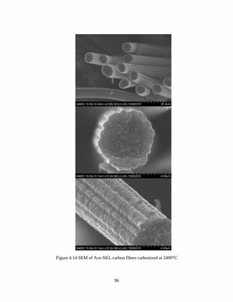
96
Figure 4.14 SEM of Ace-SKL carbon fibers carbonized at 2400°C

97
As reported in Section 3.3.2, the as-spun fibers obtained from 1.85 and 2.00 g/ml
solutions displayed sharp crevices on the fiber surfaces. One batch of such fibers (dry
spun at 50°C from 2.00 g/ml solution) was also heat treated to 1,000°C to study the effect
of microstructure on the mechanical properties. Their SEM micrographs are displayed in
Figures 4.15. It is evident that the carbon fibers retained the cross-sectional pattern from
their as-spun state, as the occlusions were formed within the carbon fibers from sharp
notches present on the precursor fiber surface.
Figure 4.15 Carbon fibers obtained from precursor fibers dry spun at 50°C of 2.00 g/ml
solution

98
Stress-strain curves of two representative single carbon fibers derived from the
2.00 and 2.15 g/ml precursor solutions are displayed in Figure 4.16. Both types of carbon
fibers display an almost linear/elastic response to failure, with similar slopes (moduli) but
different stress values at failure (strengths). As reported previously in Section 4.3.1,
carbon fibers derived from the concentrated solution (2.15 g/mL) and possessing smooth
crenulations displayed a tensile modulus of about 35 GPa (without system compliance
correction or 50 GPa after correction) and a tensile strength of 1,050 MPa. The strength
value is amongst highest reported for carbon fibers derived solely from lignin biomass. In
contrast, carbon fibers derived lower concentration of 2.00 g/ml solution displayed a
similar modulus of about 35 ± 1 GPa (without compliance correction), but their strength
was only about 790 ± 80 MPa. The similar moduli are consistent with numerous prior
observations that carbon fiber modulus is not affected by defects but usually controlled
by the extent of carbonization, which in turn is governed by the carbonization
temperature for a given type of precursor (1),(2),(3). However, carbon fiber strength is a
strong function of defects, and the lowered tensile strength observed for current carbon
fibers with occlusion-type defects can be attributed to precursor fibers containing sharp
crevices.

99
Figure 4.16 Representative stress-strain curves of single carbon fibers, obtained from two
different precursor solution concentrations (2.00 and 2.15 g/ml), displaying an almost
linear/elastic response to failure.
Another aspect that needs to be noted here is the effect of ash content. In Section
3.2.1, purification of SKL was conducted to reduce the ash content to 0.15%. Carbon
fibers produced from this purified precursor material could achieve the high strength
noted above (1050 MPa). However, in a previous batch where the ash content was 0.3%,
even with adequate tension during carbonization, the highest average strength obtained
from various batches was only 620 MPa. Thus, strength of lignin-based carbon fibers is
very sensitive to the composition of the precursor material, as metals can create defects
during carbonization, and reduce the mechanical properties dramatically. Overall, the
mechanical properties of Ace-SKL carbon fibers are much lower compared with
0
200
400
600
800
1000
1200
0 0.5 1 1.5 2 2.5 3
Stre
ss (
MP
a)
Strain (%)
Carbon fibers from 2.15 g/ml solution
Carbon fibers from 2.00 g/ml solution

100
commercial PAN-based carbon fibers such as T300 that have a tensile strength of 3.5
GPa, or mesophase pitch based carbon fibers such as P55 with a tensile modulus of 380
GPa (4). However, the mechanical properties for Ace-SKL based carbon fibers reported
here are still amongst the highest values reported for solely lignin-based carbon fibers. To
further increase the mechanical properties, a lignin precursor with high purity (ash
content below 0.1%) is required. Thus, cost-effective methods need to be developed for
purification of lignin together with other improvements, as listed in the next chapter (in
Future Work).
4.4 Conclusions
Tension was applied during thermal treatment, and resulted in a tensile strength,
modulus and strain-to-failure of 52±2 GPa, 1.05±0.07 GPa, and 2.0±0.2%, respectively.
These mechanical properties are amongst the highest values reported in the literature for
lignin-derived carbon fibers. It is also noted that the cross-section shape can be controlled
during dry-spinning, and crenulated carbon fibers obtained in this study have up to 35%
larger surface area as compared with equivalent circular fibers that are typically obtained
by melt-spinning. Due to the lack of graphitic crystallinity in these lignin-derived carbon
fibers, their surface is expected to be more reactive than that of carbon fibers processing
from graphitic precursors. Surface reactivity and larger surface area could both lead to
better fiber-matrix interfacial bonding in composites. After heat treatment at 2400°C, the
tensile strength was reduced to only 210 ± 30 MPa due to out-diffusion of noncarboneous
elements during graphitization. The Ace-SKL based carbon fibers heat treated at 1000°C

101
had a resistivity of 106 ± 12 µΩ·m, while the 2400°C heat treated fibers had a resistivity
of 63 ± 3 µΩ·m. This result is consistent with the low crystallinity in Ace-SKL carbon
fibers. Also, the low concentration precursor solution (2.00 g/ml solution) led to the
formation of carbon fibers with occlusions and resulted in reduced tensile strength as
compared with that with smooth crenulations (from 2.15 g/ml solution). In summary, the
results reported here establish the important effects of precursor composition and
processing conditions on microstructure and properties of resulting carbon fibers.

102
CHAPTER FIVE
UV-ASSISTED STABILIZATION OF ACE-SKL PRECURSOR FIBERS
5.1 Introduction
As described in Chapter 4, the stabilization of Ace-SKL based carbon fibers
consisted of a slow heating ramp that took more than 40 h to complete. The low glass
transition temperatures (Tg) of lignin precursors required a slow heating rate to achieve
crosslinking without fibers becoming tacky. Therefore, in this Chapter, ultraviolet
irradiation was used as a pre-stabilization step to help accelerate the stabilization process.
According to Braun’s analysis for continuous heating transformation (90), heating
rate during thermal stabilization needs to be below 0.06°C/min to maintain the operating
temperature below Tg of the reacting hardwood kraft lignin. Thus, it was reported that a
slower heating rate led to higher Tg (90). Kadla et al. (65) showed that hardwood kraft
lignin fibers could be thermally stabilized at a heating rate of 2°C/min. Sudo and Shimizu
(59) converted a steam exploded lignin into carbon fiber using a heating rate between 1-
2°C/min. Uraki et al. (62) prepared carbon fiber using lignin from aqueous acetic acid
pulping of hardwood with a stabilization heating rate of 0.5°C/min.
Eckert and Abdullah described carbon fibers produced from melt-spinning of a
thermally-stable acetylated softwood kraft lignin, but no tensile properties were reported
for the carbon fibers thus produced. Organosolv lignin has also been found to be sensitive
to the heating rate during thermal stabilization. A heating rate below 0.2°C/min for Alcell
lignin fibers was needed to prevent the fibers from fusing together (65). Also, in a study

103
reported by Baker et al. (74), an organic purified lignin even required a heating rate as
low as 0.01°C/min to crosslink. Organosolv lignin is readily processed compared with
other lignin precursors due to its low Tg and stable melt viscosity imparted by
substituents, but it lacks the ability to crosslink rapidly.
A DOE presentation reported on melt-spun precursor fibers obtained from a
“modified technical lignin”, with carbon fiber strength of 1.07 GPa (91). However,
further development efforts appear to be restricted by the unavailability of precursors
(lignin grades not specified) that meet stringent melt spinning requirements (75). Norberg
et al. reported a fast oxidative-stabilization using 15°C/min with fibers melt-spun from a
selected type of softwood kraft lignin, but the diameter of resulting precursor and
carbonized fibers were too thick, and no tensile properties were reported (66).
In other prior studies, UV-assisted stabilization of PAN precursor fibers was
investigated to accelerate the stabilization process using photo-sensitive precursors (19,
92-94). However, the role of UV irradiation for stabilization of lignin precursor fibers has
not been systematically addressed. Many studies have focused on reducing photo-
yellowing effect caused by light-induced deterioration of wood surfaces (95-98), but none
have taken advantage of UV irradiation to increase kinetics of stabilization for the
production of lignin-based carbon fiber. Therefore, the effect of UV radiation on
accelerating the stabilization was investigated and the results are presented in this
chapter.

104
5.2 Experimental
5.2.1 UV/Thermal dual stabilization
As-spun Ace-SKL fibers were mounted using the protocol described in section
4.2.1. The mounted fibers were hung in an oxidation oven with temperature set to
147.5°C. Weight was loaded at the bottom of fiber tows using load level of 2000 g/(g/cm)
(Load level was calculated using the equation 4.6 defined earlier). Normally, fibers
stretched up to eight times of the original length within 10 minutes of hanging, as shown
in (Figure 5.1). In this way, fiber diameter was reduced from 35 μm to about 15 μm.
Also, better alignment was achieved in the stretched fiber tows, which is desired for the
following UV treatment.
Figure 5.1 Ace-SKL fiber tows before stretching (left) and after stretching (right)
Then the stretched fiber tows were mounted in a fixture for UV irradiation, as
illustrated in Figure 5.2. One side of the tow was fixed, whereas the free end was loaded
to apply tension during UV treatment. The fiber tows were put into a UV chamber and
irradiated with a Nordson 4.5 kW UV curing lamp having a mercury bulb radiation
source. Cooling air was blown into the chamber during the irradiation procedure to
maintain the chamber temperature below 50°C, as illustrated in Figure 5.3.

105
Figure 5.2 Fiber tows mounted on UV irradiation fixture
Figure 5.3 Fiber tows in the UV chamber for irradiation
Fiber tow
UV light Fixed end
Weight

106
The UV-treated fiber tows were removed from the UV irradiation fixture and
thermo-oxidatively stabilization up to 250°C under tension and subsequently carbonized
using the method described earlier in section 4.2.1.
5.2.2 Characterization
For the FT-IR study, freshly prepared Ace-SKL powder was dissolved in acetone
to prepare a 0.03g/ml solution. 500 mg pure KBr was pressed into a 13-mm diameter
pellet using a hydraulic press. Two drops of the Ace-SKL solution were applied on the
surface of KBr pellet using a pipette and the Ace-SKL coated pellets were put into
vacuum oven at 50°C for 2 hours to fully evaporate the acetone. FT-IR spectroscopy was
performed in the transmission mode with a Thermo Nicolet Nexus 870
spectrophotometer.
Differential scanning calorimetry (DSC) was performed using a Pyris 1 DSC
(Perkin Elmer Instruments). The samples consisted of UV irradiated Ace-SKL fibers and
“control” fibers that were purposely blocked from UV radiation. The fibers were ground
into powder and the sample pans containing grounded fiber were heated from room
temperature to 250°C under N2 at a heating rate of 30°C/min and cooled to room
temperature at the same rate. For each sample, the second heating run was used to
calculate Tg using the half ΔCp method.
Gel permeation chromatography (GPC) was conducted for Ace-SKL fibers using
a Waters Alliance GPCV 2000 model equipped with a Stylegel HT4 column (Waters)
and Polargel (Agilent) column. Fibers were ground into powder and dissolved in

107
dimethylformamide solution containing 0.05 M lithum bromide at a concentration of 1
mg/mL.
5.3 Results and Discussion
5.3.1 FTIR
The Ace-SKL coated KBr pellets were irradiated in the UV chamber for 3, 10, 15,
20, and 25 min total exposure time. Also, an Ace-SKL coated “control” pellet was
wrapped in aluminum foil to block the UV but kept in the UV chamber for the same
exposure time. The FTIR spectra for various samples are displayed in Figure 5.4. For the
UV irradiated pellets, the spectra were normalized with the intensity of 1369 cm−1
band
attributed to C-H stretch in -CH3 group (44, 99), which is expected to remain fairly
unchanged due to the relatively stable –CH3 group.
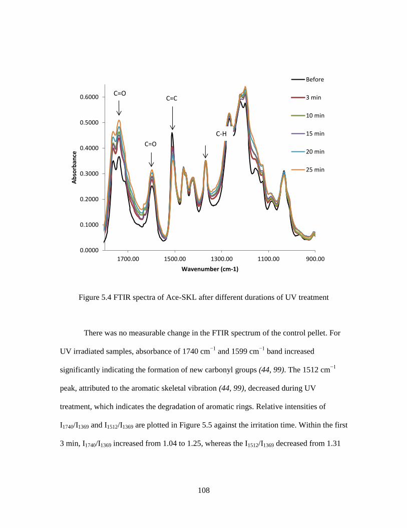
108
Figure 5.4 FTIR spectra of Ace-SKL after different durations of UV treatment
There was no measurable change in the FTIR spectrum of the control pellet. For
UV irradiated samples, absorbance of 1740 cm−1
and 1599 cm−1
band increased
significantly indicating the formation of new carbonyl groups (44, 99). The 1512 cm−1
peak, attributed to the aromatic skeletal vibration (44, 99), decreased during UV
treatment, which indicates the degradation of aromatic rings. Relative intensities of
I1740/I1369 and I1512/I1369 are plotted in Figure 5.5 against the irritation time. Within the first
3 min, I1740/I1369 increased from 1.04 to 1.25, whereas the I1512/I1369 decreased from 1.31
0.0000
0.1000
0.2000
0.3000
0.4000
0.5000
0.6000
900.001100.001300.001500.001700.00
Ab
sorb
ance
Wavenumber (cm-1)
Before
3 min
10 min
15 min
20 min
25 min
C=C C=O
C=O
C-H

109
to 1.16. Then the change of relative intensities slowed down for larger reactions times of
up to 25 min.
Figure 5.5 Relative intensity change of 1740 cm−1
and 1512 cm−1
peaks as a ratio of 1369
cm−1
peak after UV treatment for different durations
It has been reported in prior literature studies that esterification is an effective
way to prevent the photo-yellowing of paper due to the reduced formation of phenoxyl
radicals (44, 99). In the literature studies, the sensitivity of lignin to UV was dramatically
reduced when hydroxyl groups were completely substituted by ester groups. However,
our study is aimed towards increasing thermo-oxidative stabilization speed, thus hydroxyl
groups were needed in the precursor fibers. Therefore, as noted earlier in section 2.3.3,
acetylation was performed using a low acetic anhydride to lignin ratio (0.66 ml acetic
anhydride per gram of lignin) (79). Thus, the acetylation in this study was a partial

110
esterification where acetyl substituents enhanced solubility of the resulting precursor in
acetone that allowed for subsequent dry-spinning, and yet preserved a fraction of
hydroxyl groups for subsequent stabilization. As shown in the FTIR spectra, the Ace-
SKL retained sensitivity to UV and the positive effect of UV to stabilization was proven
in the following studies.
5.3.2 Thermal analysis
A 15-min UV treated fiber tow and a control fiber tow with UV blocked were
both put into oxidation oven for thermo-oxidative stabilization and subjected to a
1.2°C/min heating rate. A portion of such fibers were taken out of the oven at 100, 130,
160, 190, and 220°C, for DSC testing. Those fibers retained fiber shape without became
tacky during the entire heat treatment, as they could be separated from the bundle as
shown in Figure 5.6 (a). Control fibers removed at 160°C and higher temperatures were
almost completely fused together, as displayed in Figure 5.6 (b). An SEM image of the
fused control fibers is shown in Figure 5.7.
Figure 5.6 After thermal-oxidation up to 160°C at a heating rate of 1.2°C/min, (a) with
prior UV treatment of fibers; (b) control fibers
(a) (b)
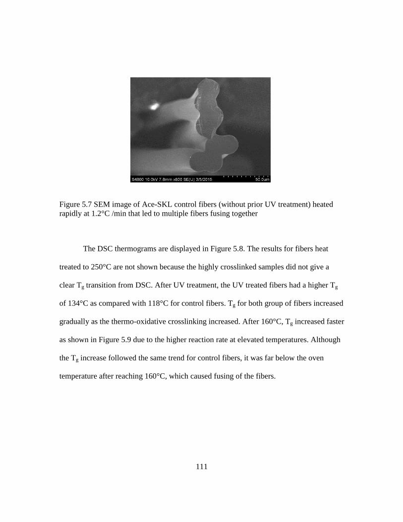
111
Figure 5.7 SEM image of Ace-SKL control fibers (without prior UV treatment) heated
rapidly at 1.2°C /min that led to multiple fibers fusing together
The DSC thermograms are displayed in Figure 5.8. The results for fibers heat
treated to 250°C are not shown because the highly crosslinked samples did not give a
clear Tg transition from DSC. After UV treatment, the UV treated fibers had a higher Tg
of 134°C as compared with 118°C for control fibers. Tg for both group of fibers increased
gradually as the thermo-oxidative crosslinking increased. After 160°C, Tg increased faster
as shown in Figure 5.9 due to the higher reaction rate at elevated temperatures. Although
the Tg increase followed the same trend for control fibers, it was far below the oven
temperature after reaching 160°C, which caused fusing of the fibers.

112
Figure 5.8 DSC thermograms of various lignin-based precursor fibers thermally treated
up to different temperatures. Solid curves: thermograms of fibers after UV irradiation;
dashed curves: thermograms of control fibers without UV exposure.
Figure 5.9 Tg shift of UV treated and control fibers as a function of thermal stabilization
temperature
100
110
120
130
140
150
160
170
180
190
200
50 100 150 200 250
T g o
calc
ula
ted
fro
m D
SC (
°C)
Environmental temperature in oven(°C)
UV irradiated Ace-SKL fibers
Control Ace-SKL fibers with UV blocked

113
5.3.3 GPC
Ace-SKL fibers UV-treated for 3 and 15 min, and a control group of fibers were
studied using GPC. The chromatograms, displayed in Figure 5.10, enabled computation
of the number average molecular weights (Mn) of 7790, 8756, and 10636 for control (no
UV), 3-min, and 15-min UV-treated samples, respectively. The corresponding weight-
average molecular weight (Mw) values were 63209, 72797, and 87163, confirming that
the molecular weight of Ace-SKL fibers after UV treatment was higher than that for the
control fibers.
Although the difference was small, the resulting molecular weights were obtained
from the whole fibers including UV-affected surface, but partially affected inner fiber
cores. Broadened peaks for fibers with 15 min UV treatment clearly indicate the presence
of a small portion of larger molecular weight fraction. This result matches with that from
previous studies which indicated that long term of UV irradiation can result in
decomposition of lignin, but at the beginning of light treatment a higher molecular weight
fraction can form due to secondary reactions (100, 101).

114
Figure 5.10 GPC chromatograms of Ace-SKL fiber samples with different UV treatment
time
5.3.4 UV/Thermal dual stabilization
As shown in Figure 5.11, the fiber diameter of stretched as-spun lignin fibers was
less than 15 µm. The crenulations on the surface described in Chapter Three were
preserved in the stretched fibers.
Figure 5.11 SEM micrographs of stretched as-spun Ace-SKL fibers at (a) low and (b)
high magnification levels.

115
SEM images of UV irradiated fibers are shown in Figure 5.12. Compared with
fibers before UV treatment, the UV treated fibers displayed a smoother surface and the
crenulations were somewhat flattened. The results also demonstrate that surface of those
fibers underwent exothermic reactions, and the heat led to some degree of softening on
the fiber surface. Tension was applied during UV irradiation to preserve molecular
orientation, as the absence of tension or inadequate tension results in shrinkage of the
fiber after UV treatment.
Figure 5.12 SEM images of UV-treated Ace-SKL fibers at (a) low and (b) high
magnification levels.
Tension was also applied during the following thermal oxidative stabilization. For
Ace-SKL fibers using a thermal stabilization alone, a slow heating ramp of 0.1-0.2°C/min
with several dwelling times was required to prevent fiber from being tacky. In contrast,
UV-treated fibers in the present study could be thermally stabilized with a fast heating
rate of 1.2°C/min without any dwell time. It is emphasized that at this fast heating rate of
1.2°C/min, the control fibers that had not been UV irradiated completely lost the fiber
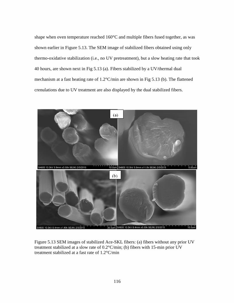
116
shape when oven temperature reached 160°C and multiple fibers fused together, as was
shown earlier in Figure 5.13. The SEM image of stabilized fibers obtained using only
thermo-oxidative stabilization (i.e., no UV pretreatment), but a slow heating rate that took
40 hours, are shown next in Fig 5.13 (a). Fibers stabilized by a UV/thermal dual
mechanism at a fast heating rate of 1.2°C/min are shown in Fig 5.13 (b). The flattened
crenulations due to UV treatment are also displayed by the dual stabilized fibers.
Figure 5.13 SEM images of stabilized Ace-SKL fibers: (a) fibers without any prior UV
treatment stabilized at a slow rate of 0.2°C/min; (b) fibers with 15-min prior UV
treatment stabilized at a fast rate of 1.2°C/min

117
The stabilized fibers obtained after UV treatment could be successfully
carbonized. Figure 5.14 (a) displays carbon fibers obtained after thermal/UV dual
stabilization involving 15 min UV irradiation followed by a fast stabilization rate
(1.2°C/min) involving only 4 hours of total stabilization time. These carbon fibers
prepared from dual stabilization method retained the crenulated shape of as-spun fibers.
For comparison purpose, carbonized fibers obtained after a slow thermal oxidative
stabilization (0.2°C/min) over 40 hours total are displayed in the micrograph of Figure
5.14 (b), which has many similarities to that in Fig 5.14 (a). Thus, the microstructural
features of carbon fibers produced from UV/rapid oxidative stabilization are similar to
those generated after single-step slow oxidative stabilization. When compared to circular
fibers with the same cross-section area, rapidly stabilized fibers in Figure 5.14 (a) have
about 15% larger surface area, which is slightly smaller than 21% larger area for carbon
fibers obtained from slow stabilization, shown in Figure 5.14 (b). When such (lignin-
based) carbon fibers will be embedded in an epoxy matrix to prepare a composite, the
larger surface area will afford a larger interfacial bonding area and will lead to better
fiber-matrix bonding.
The carbon fibers obtained from thermal/UV dual stabilization displayed a tensile
strength, modulus and strain-to-failure values of 900 ± 100 MPa, 34 ± 2 GPa, and 2.6 ±
0.2%, respectively (modulus value was without compliance correction). The
corresponding values for carbon fibers obtained after a single-step slow stabilization
process were 1050 ± 100 MPa, 35 ± 2 GPa, and 2.0 ± 0.2%, as reported earlier in Chapter
Four. Carbon fibers produced after the rapid stabilization process display about 10-20%

118
reduction in tensile strength and modulus, but about 20% increase in strain-to-failure. The
heat generated from exothermic reactions during UV treatment likely led to some
molecular relaxation within the oriented structure of the fibers, and resulted in the slight
decrease in stiffness and strength. In future studies using a continuous process, such
limitations can be overcome by increased draw-down throughout the entire process. It is
noted, however, that the tensile strength reported here is still amongst the highest ones
reported for lignin-derived carbon fibers obtained from rapid stabilization (i.e., heating
rate exceeding 1°C/min) of precursors derived from commercially available softwood
kraft lignin. As discussed earlier, some prior literature studies have reported high heating
rates of 1-2°C/min for hardwood kraft and steam exploded lignins, but those have
resulted in lower tensile strengths of 422 and 660 MPa, respectively (65),(59).

119
Figure 5.14 Carbonized Ace-SKL fibers from (a) UV/thermal dual stabilization (b) slow
thermal stabilization.
5.4 Conclusions
An acetylated softwood kraft lignin was dry-spun into fibers and UV irradiated to
induce crosslinking. The reactions induced with only 0.25 hour (15 mins) of irradiation
effectively shortened the subsequent oxidative-stabilization time from 40 to 4 hours,
which is amongst the fastest stabilization processes reported for lignin-based carbon
fibers. The increased extent of crosslinking reactions was confirmed using FTIR and
GPC analysis, and it manifested into increased glass transition temperature. Stabilized
fibers were successfully carbonized at 1000°C, and resulting carbon fibers displayed a

120
tensile strength 900 ± 100 MPa, which is amongst the highest reported for carbon fibers
derived from softwood lignin-based precursors. These results illustrate that UV
irradiation is a rapid route for shortening the stabilization time, which is often the rate-
limiting step for production of lignin-derived carbon fibers.

121
CHAPTER SIX
CONCLUSIONS AND FUTURE WORK
6.1 Conclusions
Three types of lignin were investigated in this research for the purpose of
producing bio-based carbon fibers. These included soda lignin, organosolv lignin and
softwood kraft lignin (SKL). It was concluded that soda lignin and SKL cannot be melt
spun without suitable modification. After acetylation and fractionation, soda lignin and
acetylated SKL (Ace-SKL) lignin were met spinnable but high extent of acetyl
substitution prevented the subsequent thermal stabilization. It was shown that ECN lignin
was successfully melt spun into as-spun fibers. However, the thermally oxidative
stabilization took a very long time to complete. Controlled acetylation was performed on
SKL. The resulting precursor could be dry-spun using acetone as solvent and thermally
stabilized in air atmosphere, a method that has not been reported in prior literature. The
stabilized fibers were successfully carbonized, and it established a novel route for
producing carbon fibers from softwood kraft lignin.
Shear viscosity of Ace-SKL solutions displayed a significant shear-thinning
behavior at all temperatures studied. The viscosity results could be modeled with power-
law exponents ranging from 0.33 to 0.82, confirming the macromolecular nature of the
Ace-SKL lignin/acetone solutions. As expected, elevated temperatures led to lower
viscosities and facilitated extrusion at pressures under 10 MPa (about 1500 psi). As-spun
fibers produced from dilute solutions (1.85 and 2.00 g/mL) developed some sharp
crevices on the fiber surface. These are undesirable for subsequent processing of resulting

122
carbon fibers into composites by resin-infusion. For the most concentrated solution
investigated in this study, 2.15 g/mL, the resulting fibers contained no sharp crevice. All
fibers produced by the dry-spinning process led to crenulated fiber surface, with the
highest spinning temperature leading to most crenulations. About 35% larger surface area
could be achieved in Ace-SKL as-spun fibers (as compared with equivalent circular
fibers), indicating the potential of such biomass-derived fibers in providing larger
fiber/matrix bonding area when used in composites.
Tension was applied during both stabilization and carbonization steps. With
adequate tension, Ace-SKL based carbon fibers displayed tensile strength, modulus and
strain-to-failure of 52±2 GPa, 1.05±0.07 GPa, and 2.0±0.2 %, respectively. These tensile
properties are amongst the highest values reported in the literature for lignin-derived
carbon fibers. The crenulated patterns of precursor fiber cross-section shape were
preserved in carbon fibers, and up to 35 % larger surface area was obtained as compared
with equivalent circular fibers. The Ace-SKL carbon fibers had low graphitic crystallinity,
so their surface is expected to be more active than that of carbon fibers possessing a
higher graphitic structure. Larger surface area and surface reactivity could both lead to
better fiber-matrix interfacial bonding when such carbon fibers are used in composites.
One limitation of the above process is that the thermal stabilization took around
40 hours to complete. To reduce the time duration required for stabilization, UV
irradiation was employed as a way to induce crosslinking. Ace-SKL as-spun fibers were
irradiated with UV for 0.25 hours (15 min) followed by thermo-oxidative stabilization,
which took only 4 hours. It is amongst the fastest stabilization processes reported for

123
lignin-based carbon fibers. The effect of UV was investigated using DSC, FTIR and GPC
analysis. The resulting carbon fibers from UV/thermal dual stabilization displayed a
tensile strength of 900 ± 100 MPa, which is amongst the highest reported for carbon
fibers derived from softwood lignin-based precursors. UV irradiation was confirmed as a
useful way for shortening the stabilization time of lignin-based carbon fibers.
6.2 Future Work
The SKL used in this study has a wide molecular weight distribution. It is desired
that narrower molecular weight distribution be obtained by a suitable fractionation
method, either before or after the acetylation reaction. Also, 0.66 g lignin per ml acetic
anhydride was used in the acetylation reaction in this study. The content of acetic
anhydride could be reduced further in order to preserve more hydroxyl groups within the
precursor material. Higher content of hydroxyl group means faster stabilization. Since the
reaction mixture was already in a very thick and viscous status, adding certain solvents
into the reaction mixture could dilute the acetic anhydride and improve mixing.
Other precursors such as soda lignin and ECN organosolv lignin has been
explored in this work, but the study mainly focused on melt-spinning. It is possible that
the acetylated soda lignin could be dry spun using acetone as a solvent. Also, proper
solvent for the modified or unmodified ECN lignin could possibly be found for dry-
spinning. The compatibility of various types of lignin and solvents such as acetic acid
could be studied. It would be a good potential for another lignin/solvent system which is

124
capable of dry-spinning, as carbon fibers derived from dry-spinning has increased surface
area which is favorable for fiber/matrix bonding with epoxy.
In Chapter Three, the rheology of Ace-SKL solutions under high shear rate was
studied but accurate results for low-shear viscosity was difficult to obtain due to solvent
evaporation using cone and plate rheometer. In addition, dynamic rheology results of the
Ace-SKL solutions were not available due to the same evaporation problem. Proper
design of enclosure system outside the cone and plate or parallel plate fixture would be
needed for those types of measurement. Further more, the extensional viscosity is an
important rheological property for spinning solutions. A suitable lubricant system needs
to be developed to reduce shear effect between the solution and the wall of hyperbolic die,
to provide a nearly pure extensional flow.
Some preliminary work has been done to convert Ace-SKL based carbon fibers
into composites. Due to limitations of lab-scale experiments, Ace-SKL carbon fibers
were produced at a small scale (up to 150 mg per batch), which is not enough for the
preparation of a relatively large piece of composite sample. Several 1 cm × 5 cm Ace-
SKL carbon fibers/epoxy composites were prepared but resulted in poor alignment of
fibers in the composite samples. If the Ace-SKL carbon fibers could be prepared in a
continuous form, better alignment can be achieved, which is important for producing high
performance composites.
To properly scale up the process, a purification unit with larger capacity is needed.
Currently, only 50 gram of SKL could be obtained after each purification batch with 25
cycles of washing and filtration. Larger amount of raw material is necessary to feed into a

125
continuous spinning unit. Also, a reactor is needed to replace the flask currently used for
acetylation reaction. Finally, continuous carbonization and stabilization facility equipped
with multiple rolls to provide tension during heat treatment can lead to significant process
improvement. Adjustable tension during heat treatment, especially carbonization, is
crucial to prevent fiber breakage.
While the positive role that the crenulated surface morphology can play has been
noted earlier, the fiber/matrix bonding behavior of Ace-SKL carbon fibers in epoxy resin
was not studied yet. In future studies, carbon fibers derived from Ace-SKL should be
surface treated and then the fiber interfacial bonding strength could be measured using
micro-bead method or fragmentation method. If micro-bead method is used, appropriate
technique need to be developed to generate a small enough epoxy bead around a single
carbon fiber. Fragmentation method also requires a sophisticated sample preparation with
single fiber aligned and embedded in epoxy. In addition, the surface chemistry properties
of Ace-SKL carbon fibers could be studied using proper techniques.
UV irradiation assisted stabilization was performed in this study on Ace-SKL as-
spun fibers, but it could be applied on other lignin precursors such as organosolv lignin or
hardwood kraft lignin. Also, UV initiator could be introduced into the lignin precursors
which have been chemically modified with UV-sensitive functional groups. In this way,
the stabilization time could be significantly reduced by UV-induced cross-linking.
In summary, lab-scale studies were conducted in a batch-mode during the course
of this research and have elucidated several scientific aspects of dry-spinning of

126
acetylated lignin. Subsequently, the precursor fibers were successfully carbonized to
produce carbon fibers with tensile properties that are amongst the best reported in the
literature for lignin-derived carbon fibers. Future improvement in precursor composition
and processing step suggested above can help with further improvements in resulting
carbon fibers and push their application into industrially relevant composite materials.

127
REFERENCES
1. Fitzer, E.; Manocha, L. M. Carbon reinforcements and carbon/carbon composites;
Springer: Berlin, 1998; pp 17-28.
2. Edie, D. D.; Diefendorf, R. J. In Carbon Fiber Manufacturing; Buckley, J. D., Edie, D.
D., Eds.; Carbon-Carbon Materials and Composites; Noyes Publications: Park Ridge,
1993; pp 20-33.
3. Figueiredo, J. L.; Bernardo, C.; Baker, R. T. K.; Hüttinger, K. J. Carbon Fibers
Filaments and Composites; Series E: Applied Sciences; Kluwer Academic
Publishers: Dordrecht, The Netherlands, 1990; Vol. 177, pp 4-14.
4. Peebles, L. Carbon Fibers, Formation, Structure and Properties; Carbon Fibers,
Formation, Structure and Properties; CRC Press: Boca Raton, 1995; , pp 7-24.
5. Bunsell, A. R.; Renard, J. Fundamentals of Fibre Reinforced Composite Materials;
IOP Publishing Ltd: London, 2005; pp 3-5.
6. Hull, D.; Clyne, T. An introduction to composite materials; Cambridge university
press: 1996; .
7. Ventura, G.; Martelli, V. Thermal conductivity of Kevlar 49 between 7 and 290K.
Cryogenics 2009, 49, 735-737.
8. Roger, B. United States Patent US 2957756 A, 1960.
9. Bacon, R.; Cranch, G. E.; Moyer, R. 0.; Watts, W. H. US Patent 3,305,315, 1967.
10. Shindo, A. United Kindom Patent 911542, 1960.
11. Ōtani, S. On the carbon fiber from the molten pyrolysis products. Carbon 1965, 3,
31-38.
12. Liu, Y.; Kumar, S. Recent progress in fabrication, structure, and properties of carbon
fibers. Polymer Reviews 2012, 52, 234-258.
13. Sittig, M., Ed.; In Carbon and graphite fibers: manufacture and applications; Noyes
Data Corporation: Park Ridge, New Jersey, 1980; .
14. Clarke, A.; Bailey, J. Oxidation of acrylic fibres for carbon fibre formation. 1973.
128
15. Morales, M. S.; Ogale, A. A. Wet‐spun, photoinitiator‐modified polyacrylonitrile
precursor fibers: UV‐assisted stabilization. J Appl Polym Sci 2013, 130, 2494-2503.
16. Bajaj, P.; Roopanwal, A. Thermal stabilization of acrylic precursors for the
production of carbon fibers: an overview. Journal of Macromolecular Science, Part
C: Polymer Reviews 1997, 37, 97-147.
17. Paiva, M. C.; Kotasthane, P.; Edie, D. D.; Ogale, A. A. UV stabilization route for
melt-processible PAN-based carbon fibers. Carbon 2003, 41, 1399-1409.
18. Delmonte, J. Technology of carbon and graphite fiber composites. 1981.
19. Morales, M. S.; Ogale, A. A. Carbon fibers derived from UV‐assisted stabilization of
wet‐spun polyacrylonitrile fibers. J Appl Polym Sci 2014, 131.
20. Diefendorf, R.; Tokarsky, E. High‐performance carbon fibers. Polymer Engineering
& Science 1975, 15, 150-159.
21. Sjostrom, E. Wood chemistry: fundamentals and applications; Academic Press:
Oxford, 1993; , pp 71-77.
22. Singer, L. S. United States Patent US 4005183, 1977.
23. Mochida, I.; Korai, Y.; Ku, C.; Watanabe, F.; Sakai, Y. Chemistry of synthesis,
structure, preparation and application of aromatic-derived mesophase pitch. Carbon
2000, 38, 305-328.
24. Esguerra, D. F.; Hoffman, W. P.; Thies, M. C. Fractionation of an oligomeric pyrene
pitch via supercritical extraction. The Journal of Supercritical Fluids 2013, 79, 170-
176.
25. Esguerra, D. F.; Hoffman, W. P.; Thies, M. C. Liquid crystallinity in trimer oligomers
isolated from petroleum and pyrene pitches. Carbon 2014, 79, 265-273.
26. Diefendorf, R. J.; Riggs, D. M. United States Patent US 4208267, 1980.
27. Kundu, Santanu, and Amod A. Ogale. "Rheostructural studies on a synthetic
mesophase pitch during transient shear flow." Carbon 2006, 44, 2224-2235.
28. Edie, D.; Dunham, M. Melt spinning pitch-based carbon fibers. Carbon 1989, 27,
647-655.

129
29. Edie, D. D. In Pitch and Mesophase Fibers. Figueiredo, J. L., Bernardo, C., Baker, R.
and Hüttinger, K. J., Eds.; Carbon fibers, filaments and composites; Kluwer
Academic Pulb.: 1990; pp 647-655.
30. Endo, M. Structure of mesophase pitch-based carbon fibres. J. Mater. Sci. 1988, 23,
598-605.
31. Bahl, O. P.; Shen, Z.; Lavin, J. G.; Ross, R. A. In Manufacture of carbon fibers;
Donnet, J., Bansal, R. C., Eds.; Carbon fibers; Marcel Dekker, Inc.: New York, 1998;
pp 31.
32. Riggs, D. M.; Shuford, R. J.; Lewis, R. W. In Graphite fibers and composites; Lubin,
G., Ed.; Handbook of composites; Springer: New York, 1982; pp 196-271.
33. Fitzer, E. In Carbon fibres—present state and future expectations; Figueiredo, J. L.,
Bernardo, C., Baker, R. T. K. and Hüttinger, K. J., Eds.; Carbon Fibers, Filaments
and Composites; Kluwer Academic Publ.: 1990; pp 3-41.
34. Bacon, R. Carbon fibers from rayon precursors. Chem. Phys. Carbon 1973, 9, 1-102.
35. Rouhi, A. M. Only facts will end the lignin war. Chem.Eng.News (April 2) 2001, 52-
56.
36. Vakkilainen, E. In Chemical recovery; Gullichsen, J., Paulapuro, H., Eds.;
PaperMaking Science and Technology, Book 6B. Fapet Oy: Helsinki, 2000; pp 6-34.
37. Sandermann Jr, H.; Scheel, D.; Trenck, T. In In Metabolism of environmental
chemicals by plants-copolymerization into lignin; J. Appl. Polym. Sci.: Appl. Polym.
Symp.; The ninth cellulose conference
Jan 1, 1983; .
38. Payen, A. Mémoire sur la composition du tissu propre des plantes et du ligneux.
Comptes rendus 1838, 7, 1052-1056.
39. Sarkanen, K. V.; Ludwig, C. H. In Definition and nomenclature; Sarkanen, K. V.,
Ludwig, C. H., Eds.; Lignins: occurrence, formation, structure and reactions
; John Wiley & Sons, Inc.: Toronto, 1971; pp 2.
40. Harborne, J. B. Biochemistry of phenolic compounds. Biochemistry of phenolic
compounds. 1964, 373-382.
41. Freudenberg, K. Chim., Biochim., Lignine, Cellulose et Hemicellulose. 1964, 39.

130
42. McCarthy, J. L.; Islam, A. In Lignin Chemistry, Technology, and Utilization: A Brief
History; Glasser, W. G., Northey, R. A. and Schultz, T. P., Eds.; Lignin: historical,
biological, and materials perspectives; American Chemical Society Washington, DC:
2000; pp 2-99.
43. Björklund, J. M.; Nilvebrant, N. In Wood extractives; Ek, M., Gellerstedt, G. and
Henriksson, G., Eds.; Ljungberg Textbook: Pulp and Paper Chemistry and
Technology; Fibre and Polymer Technology, KTH: Stockholm, 2007; Vol. 1, pp
317-356.
44. Faix, O. Classification of lignins from different botanical origins by FT-IR
spectroscopy. Holzforschung-International Journal of the Biology, Chemistry,
Physics and Technology of Wood 1991, 45, 21-28.
45. Glasser, W. G.; Barnett, C. A.; Sano, Y. In In Classification of lignins with different
genetic and industrial origins; J. Appl. Polym. Sci.: Appl. Polym. Symp.;(United
States); Virginia Polytechnic Inst. and State Univ., Blacksburg: 1983; .
46. Glasser, W. G.; Wright, R. S. Steam-assisted biomass fractionation. II. Fractionation
behavior of various biomass resources. Biomass Bioenergy 1998, 14, 219-235.
47. Kocurek, M. J.; Grace, T.; Malcolm, E. Pulp and paper manufacture: Alkaline
pulping; Tappi Pr: 1989; Vol. 5.
48. Lai, Y. Z.; Sarkanen, K. V. In Isolation and structural studies; Sarkanen, K. V.,
Ludwig, C. H., Eds.; Lignins: occurrence, formation, structure and reactions; John
Wiley & Sons, Inc.: Toronto, 1971; pp 188.
49. Chakar, F. S.; Ragauskas, A. J. Review of current and future softwood kraft lignin
process chemistry. Ind. Crops. Prod. 2004, 20, 131-141.
50. Gellerstedt, G.; Lindfors, E. Structural changes in lignin during kraft cooking. Part 4.
Phenolic hydroxyl groups in wood and kraft pulps. Svensk Papperstidn 1984, 87,
R115-R118.
51. Biermann, C. J. Essentials of pulping and papermaking; Academic Press: San Diego,
1993; , pp 93.
52. Notley, S. M.; Norgren, M. In Lignin: Functional biomaterial with potential in
surface chemistry and nanoscience; Lucia, L. A., Rojas, O., Eds.; The nanoscience
and technology of renewable biomaterials; John Wiley & Sons, Ltd Chichester: 2009;
pp 173-206.

131
53. Johansson, A.; Aaltonen, O.; Ylinen, P. Organosolv pulping—methods and pulp
properties. Biomass 1987, 13, 45-65.
54. Chang, P.; Paszner, L. US Patent 4,594,130, 1986.
55. Kleinert, T. N. Organosolvent pulping with aqueous alcohol. Tappi 1974, 57, 99-102.
56. Nimz, H.; Casten, R. In In Organosolv pulping with acetic acid. Procs. 3th ISWPC,
Vancouver, BC, Canada, 1985, 265-266. 1985; , pp 265-266.
57. Diebold, V. B.; Cowan, W. F.; Walsh, J. K. US Patent 4,100,016, 1978.
58. Otani, S.; Fukuoka, Y.; Igarashi, B.; Sasaki, K. US Patent 3,461,082, 1969.
59. Sudo, K.; Shimizu, K. A new carbon fiber from lignin. J. Appl. Polym. Sci. 1992, 44,
127-134.
60. Sudo, K.; Shimizu, K.; Nakashima, N.; Yokoyama, A. A new modification method of
exploded lignin for the preparation of a carbon fiber precursor. J Appl Polym Sci
1993, 48, 1485-1491.
61. Kubo, S.; Uraki, Y.; Sano, Y. Thermomechanical analysis of isolated lignins.
Holzforschung 1996, 50, 144-150.
62. Uraki, Y.; Kubo, S.; Nigo, N.; Sano, Y.; Sasaya, T. Preparation of carbon fibers from
organosolv lignin obtained by aqueous acetic acid pulping. Holzforschung 1995, 49,
343-350.
63. Kubo, S.; ISHIKAWA, Naoya; Uraki, Y.; Sano, Y. Preparation of Lignin Fibers from
Softwood Acetic Acid Lignin Relationship between fusibility and the chemical
structure of lignin. Journal of the Japan Wood Reseach Society 1997, 43, 655-662.
64. Kubo, S.; Uraki, Y.; Sano, Y. Preparation of carbon fibers from softwood lignin by
atmospheric acetic acid pulping. Holzforschung 1998, 36, 1119-1124.
65. Kadla, J.; Kubo, S.; Venditti, R.; Gilbert, R.; Compere, A.; Griffith, W. Lignin-based
carbon fibers for composite fiber applications. Carbon 2002, 40, 2913-2920.
66. Norberg, I.; Nordström, Y.; Drougge, R.; Gellerstedt, G.; Sjöholm, E. A new method
for stabilizing softwood kraft lignin fibers for carbon fiber production. J. Appl.
Polym. Sci. 2012, 128(6), 3824-3830.
67. Nordström, Y.; Norberg, I.; Sjöholm, E.; Drougge, R. A new softening agent for melt
spinning of softwood kraft lignin. J. Appl. Polym. Sci. 2013, 129, 1274-1279.

132
68. Nordström, Y.; Joffe, R.; Sjöholm, E. Mechanical characterization and application of
Weibull statistics to the strength of softwood lignin‐based carbon fibers. J. Appl.
Polym. Sci. 2013, 130, 3689-3697.
69. Maradur, S. P.; Kim, C. H.; Kim, S. Y.; Kim, B.; Kim, W. C.; Yang, K. S.
Preparation of carbon fibers from a lignin copolymer with polyacrylonitrile. Synth.
Met. 2012, 162, 453-459.
70. Xia, K.; Ouyang, Q.; Chen, Y.; Wang, X.; Qian, X.; Wang, L. Preparation and
characterization of lignosulfonate-acrylonitrile copolymer as a novel carbon fiber
precursor. ACS Sustainable Chem. Eng. 2016, 4, 159-168.
71. Dong, X.; Lu, C.; Zhou, P.; Zhang, S.; Wang, L.; Li, D. Polyacrylonitrile/lignin
sulfonate blend fiber for low-cost carbon fiber. RSC Advances 2015, 5, 42259-42265.
72. Qin, W.; Kadla, J. Effect of organoclay reinforcement on lignin-based carbon fibers.
Ind Eng Chem Res 2011, 50, 12548-12555.
73. Eckert, R. C.; Abdullah, Z. Carbon fibers from kraft softwood lignin 2008.
74. Baker, D. A.; Gallego, N. C.; Baker, F. S. On the characterization and spinning of an
organic‐purified lignin toward the manufacture of low‐cost carbon fiber. J. Appl.
Polym. Sci. 2012, 124, 227-234.
75. Baker, D. A.; Rials, T. G. Recent advances in low‐cost carbon fiber manufacture from
lignin. J. Appl. Polym. Sci. 2013, 130(2), 713-728.
76. Baker, D. A.; Gallego, N. C.; Baker, F. S. On the characterization and spinning of an
organic-purified lignin toward the manufacture of low-cost carbon fiber. J Appl
Polym Sci 2012, 124, 227-234.
77. Zhang, M.; Ogale, A. A.
Effect of Temperature and Concentration of Acetylated-Lignin Solutions On Dry-
Spinning of Carbon Fiber Precursors. Journal of Applied Polymer Science.
Submitted.
78. Zhang, M.; Ogale, A. A. In Carbon Fibers Derived from Acetylated Softwood Kraft
Lignin; Naskar, A. K., Hoffman, W. P., Eds.; ACS Symposium Series: Polymer
Precursor-Derived Carbon; American Chemistry Society: Washington, DC, 2014;
Vol. 1173, pp 137-152.
79. Zhang, M.; Ogale, A. A. Carbon fibers from dry-spinning of acetylated softwood
kraft lignin. Carbon 2013, 69, 626-629.

133
80. Zhang, M.; Jin, J.; Ogale, A. A. Carbon Fibers from UV-Assisted Stabilization of
Lignin-Based Precursors. Fibers 2015, 3, 184-196.
81. Kent, J. A. In Kent and Riegel’s Handbook of Industrial Chemistry and
Biotechnology, Vol. 1; Springer: New York, 2007; pp 434-435.
82. Bagley, E.; Schreiber, H. Effect of die entry geometry on polymer melt fracture and
extrudate distortion. Transactions of The Society of Rheology (1957-1977) 1961, 5,
341-353.
83. Tadmor, Z.; Gogos, C. G. In Principles of polymer processing; Wiley: New York,
2013; pp 569.
84. Alway-Cooper, R. M.; Anderson, D. P.; Ogale, A. A. Carbon black modification of
mesophase pitch-based carbon fibers. Carbon 2013, 59, 40-48.
85. Ozbek, S.; Isaac, D. Strain-induced density changes in PAN-based carbon fibres.
Carbon 2000, 38, 2007-2016.
86. Tsai, J.; Lin, C. The effect of the side chain of acrylate comonomers on the
orientation, pore‐size distribution, and properties of polyacrylonitrile precursor and
resulting carbon fiber. J Appl Polym Sci 1991, 42, 3039-3044.
87. Edie, D. The effect of processing on the structure and properties of carbon fibers.
Carbon 1998, 36, 345-362.
88. Qin, W.; Kadla, J. Carbon fibers based on pyrolytic lignin. J. Appl. Polym. Sci. 2012,
126.
89. Salmén, L.; Bergnor, E.; Olsson, A.; Åkerström, M.; Uhlin, A. Extrusion of Softwood
Kraft Lignins as Precursors for Carbon Fibres. BioResources 2015, 10, 7544-7554.
90. Braun, J.; Holtman, K.; Kadla, J. Lignin-based carbon fibers: Oxidative
thermostabilization of kraft lignin. Carbon 2005, 43, 385-394.
91. Warren, C. D.; Naskar, A. K. In In Presentation at 2012 DOE
Hydrogen and Fuel Cells Program and Vehicle Technologies
Program Annual Merit Review and Peer Evaluation
Meeting; May 16, 2012; .
92. Paiva, M.; Kotasthane, P.; Edie, D.; Ogale, A. UV stabilization route for melt-
processible PAN-based carbon fibers. Carbon 2003, 41, 1399-1409.

134
93. Naskar, A. K.; Walker, R. A.; Proulx, S.; Edie, D. D.; Ogale, A. A. UV assisted
stabilization routes for carbon fiber precursors produced from melt-processible
polyacrylonitrile terpolymer. Carbon 2005, 43, 1065-1072.
94. Morales, M. S.; Ogale, A. A. UV‐induced crosslinking and cyclization of solution‐cast polyacrylonitrile copolymer. J Appl Polym Sci 2013, 128, 2081-2088.
95. Plackett, D.; Dunningham, E.; Singh, A. Weathering of chemically modified wood.
Holz als Roh-und Werkstoff 1992, 50, 135-140.
96. Heitner, C. In In Light-induced yellowing of wood-containing papers: An evolution of
the mechanism; ACS symposium series (USA); 1993; .
97. Feist, W. C.; Rowell, R. M.; Ellis, W. D. Moisture sorption and accelerated
weathering of acetylated and methacrylated aspen. Wood Fiber Sci. 1991, 23, 128-
136.
98. Chang, H.; Su, Y.; Chang, S. Studies on photostability of butyrylated, milled wood
lignin using spectroscopic analyses. Polym. Degrad. Stab. 2006, 91, 816-822.
99. Paulsson, M.; Simonson, R. In Acetylation of lignin and photostabilization of lignin-
rich mechanical wood pulp and paper; Chemical Modification, Properties, and
Usage of Lignin; Springer: 2002; pp 221-245.
100. Koch, H.; Hübner, K.; Fischer, K. The influence of light on the molecular mass of
lignin. J. Wood Chem. Technol. 1994, 14, 339-349.
101. Fischer, K.; Beyer, M. Comparison of light-induced and heat-induced yellowing of
pulp. Lenzinger Berichte 2000, 79, 25-31.
102. Maire, J., & Mering, J. (1970). Graphitization of soft carbons. Chemistry and
physics of carbon, 6, 125-190.

APPENDICES
135

A.1 Bagley correction of Ace-SKL solutions
In Chapter three, the viscosity of Ace-SKL solutions with different concentrations
was discussed. High shear viscosities were obtained from capillary rheometer after
Bagley correction. The shear rate (��), measured pressure drop (∆𝑃𝑎𝑝𝑝), slope of trend
lines obtained from plotting ∆𝑃𝑎𝑝𝑝 against L/D, corrected shear stress 𝜏𝑅, and corrected
viscosity 𝜂 are listed in Table A.1. Figure A.1 lists Bagley plots of various concentration /
temperature combinations. As noted in Section 3.2.2, ∆𝑃𝑎𝑝𝑝 obtained under selected shear
rates was plot against L/D. For each ��, the slopes of trend lines in Figure A.1 equal to
4𝜏𝑅, thus 𝜏𝑅 was calculated from the slope values, and corrected shear viscosity was
obtained with 𝜏𝑅/𝛾.
136

137
Table A.1 Original data obtained from capillary rheometer for Bagley correction
Concentration,
temperature �� (s
-1)
∆𝑃𝑎𝑝𝑝 (MPa) Slope
(MPa) 𝜏𝑅
(MPa) 𝜂 (Pa·s)
L/D=25 L/D=15 L/D=5
2.15 g/ml
acetone,25°C
10000 39.9 30.2 20.6 0.97 0.24 24
6000 39.6 28.9 18.7 1.05 0.26 44
3000 39.1 27.7 15.9 1.16 0.29 97
2.15 g/ml
acetone,50°C
10000 17.2 12.1 6.6 0.53 0.13 13
6000 13.8 9.1 4.7 0.45 0.11 19
3000 8.9 5.7 2.8 0.31 0.08 26
2.00 g/ml
acetone,25°C
10000 33.7 23.7 15.9 0.89 0.22 22
6000 31.1 22.9 14.0 0.85 0.21 36
3000 29.1 19.6 11.1 0.90 0.22 75
2.00 g/ml
acetone,40°C
10000 18.7 13.7 7.3 0.57 0.14 14
6000 15.2 10.9 5.4 0.49 0.12 20
3000 10.5 7.1 3.3 0.36 0.09 30
1.85 g/ml
acetone,25°C 10000 28.5 21.6 13.4 0.76 0.19 19
6000 26.9 19.6 11.5 0.77 0.19 32
3000 22.9 16.1 8.5 0.72 0.18 60
1.85 g/ml
acetone,35°C
10000 21.0 14.5 7.6 0.67 0.17 17
6000 17.1 11.6 5.7 0.57 0.14 24
3000 11.9 7.9 3.6 0.41 0.10 35

138
0
5
10
15
20
25
30
35
40
45
0 10 20 30
ΔP
(M
Pa
)
L/D
2.15 g Ace-SKL / mL acetone, 25oC
10000 s⁻¹
6000 s⁻¹
3000 s⁻¹
0
2
4
6
8
10
12
14
16
18
20
0 10 20 30
ΔP
(M
Pa
)
L/D
2.15 g Ace-SKL / mL acetone, 50oC
10000 s⁻¹
6000 s⁻¹
3000 s⁻¹
0
5
10
15
20
25
30
35
40
0 10 20 30
ΔP
(M
Pa
)
L/D
2.00 g Ace-SKL/mL acetone, 25oC
10000 s⁻¹
6000 s⁻¹
3000 s⁻¹

139
Figure A.1 Bagley plots of various concentration / temperature combinations
0
2
4
6
8
10
12
14
16
18
20
0 10 20 30
ΔP
(M
Pa
)
L/D
2.00 g Ace-SKL/mL acetone, 40oC
10000 s⁻¹
6000 s⁻¹
3000 s⁻¹
0
5
10
15
20
25
30
35
0 10 20 30
ΔP
(M
Pa
)
L/D
1.85 g Ace-SKL / ml acetone, 25oC
10000 s⁻¹
6000 s⁻¹
3000 s⁻¹
0
5
10
15
20
25
0 10 20 30
ΔP
(M
Pa
)
L/D
1.85 g Ace-SKL / ml acetone, 35oC
10000 s⁻¹
6000 s⁻¹
3000 s⁻¹

A.2 Elongational viscosity measurement
Elongational viscosity was measured with ACER 2000 capillary rheometer
equipped with hyperbolic dies. In this measurement, the extensional rate was calculated
using equation (A.1), where ε is the elongational rate, v0 is the initial velocity of fluid at
the die entrance, L is the length of the hyperbolic die, and εH is the Hencky strain. The
effective elongational viscosity (ηeff) was calculated using equation (A.2), where ΔP is
the measured pressure drop. The Hencky strain of hyperbolic die used was 4.
ε = (v0
L)(expεH − 1)
(
(A.1)
ηeff =ΔP
εεH
(
(A.2)
Other than the well-developed shear rheometry, another aspect that is significant
to spinning is the elongational rheology. In this study, hyperbolic die was applied to
create a controlled flow field with constant elongational rate. However, equation (1) and
(2) was applied assuming that there is no shear flow within the hyperbolic die, which is
almost impossible without adequate lubrication between die wall and fluid. The measured
ηeff of a 2.15 g/ml acetone Ace-solution at different ε is shown in Figure A.3. It can be
seen that, ηeff at ε of 1 s-1 was above 100,000 Pa·s, which is much higher than the
predicted value of 2000-3000 Pa·s, because in the Troutons’s rule (ηe =3 η(γ )). The
extremely high ηeff is attributed to a large shear component within the flow. This leads to
140

141
an excess pressure drop than that generated by pure extensional flow and results in
possible inaccurate extensional viscosity.
Figure A.2 Effective extensional viscosity of 2.15 g/ml acetone Ace-SKL solution
measured at 25°C
Several trials were performed to induce slip between die wall and Ace-SKL
solution. For example, the die wall was sprayed with mold release or coated with a thin
layer of Vaseline, but the results were similar with that shown in Figure A.2. In another
trial, Ace-SKL solution was shaped into long cylinder and Vaseline was applied on the
surface of shaped solution. However, Vaseline worked as a plasticizer which obviously
softened the solution thus the data was not reliable.
10000
100000
1000000
0.1 1 10
Eff
ecti
ve
ext.
eta
(P
a-s
)
Extensional rate (s-1)

A.3 Ace-SKL as-spun fibers shape analysis using SEM
Scanning electron microscopy (SEM, Hitachi S4800) was used to analyze the
cross-section shape and dimension. The as-spun fibers were coated with platinum using a
sputter coater. To obtain accurate cross-section areas and perimeters, the fibers need to be
aligned perpendicular to the lens of microscope. In this section, the adjustment procedure
of fiber orientation will be described.
After regular sample loading of SEM, a single fiber needs to be roughly focused
as shown in Figure A.3(a). The fiber in this image was not perpendicular to the lens. The
first step is to rotate the sample stage and get the lateral surface of fiber be perpendicular
to the horizontal line of screen. The “rotation” and “tilt” feature in the SEM software was
shown in Figure A.4, and “Eucentric” need to be checked. In this example, the fiber was
rotated 292 degrees (Figure A.3 (b)). Then the sample stage needs to be tilted. Input a
proper tilt angle as shown in Figure A.3. Figure A.3 (c) is the resulting image of this fiber
tilt 2 degrees, and Figure A.3 (d) is the resulting image of 4.5 degrees tilting. It can be
seen that in Figure A.3 (d), no lateral surface could be observed, which means a good
alignment of the fiber. Then this single fiber could be furtherly focused under higher
magnification.
142

143
Figure A.3 Adjustment of single fiber alignment using “rotation” and “tilt” feature of
SEM
(a) (b)
(c) (d)

Figure A.4 “Rotation” and “tilt” feature in SEM software
Once an image is captured for a single fiber, it will be exported to Quartz PCI
software for analysis. The “freehand shape measuring tool” is shown in Figure A.5. After
click this tool, the mouse cursor will change to pen-shape. A closed line could be drawn
along the fiber edge and the cross-sectional area and perimeter will displayed. Ten
images was captured and analyzed for each group of fibers. An example group of images
for Ace-SKL as-spun fibers is displayed in Figure A.6.
144
Rotation
angle
Tilt
angle

145
Figure A.5 “Freehand shape measuring tool” in Quartz PCI.
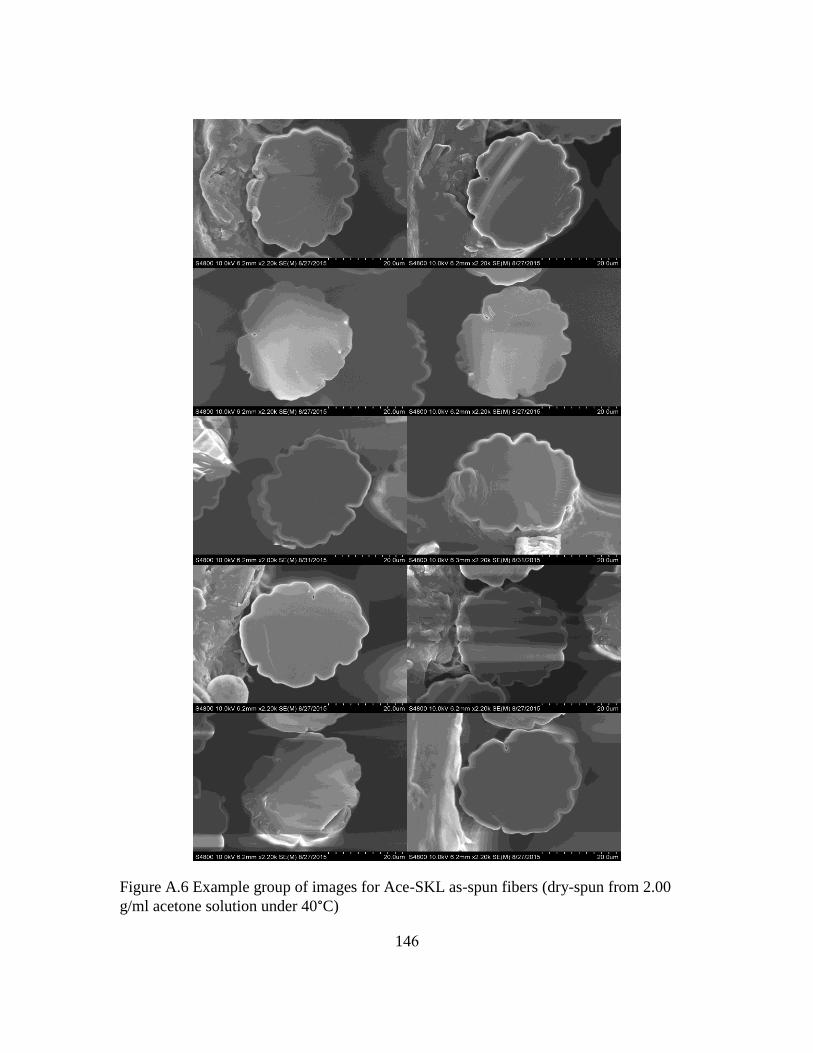
146
Figure A.6 Example group of images for Ace-SKL as-spun fibers (dry-spun from 2.00
g/ml acetone solution under 40°C)

147
A.4 Compliance Measurement
In equation (A.3), ∆l is calculated from total length change ∆lt by subtracting the
slippage distance ∆ls. Equation (A.3) is rearranged to equation (A.5), thus in equation
(A.6), compliance C was calculated as ∆lt/f, and system compliance CSwas calculated as
∆ls/f. C was plotted against l/A, and the slope is 1/E. In this way the corrected E can be
calculated. Figure A.7 is one of the compliance plot example.
∆𝑙𝑡
𝑓=
𝑙
𝐴∙
1
𝐸+
∆𝑙𝑆
𝑓(A.5)
𝐶 =𝑙
𝐴∙
1
𝐸+ 𝐶𝑆 (A.6)
𝐸 =𝜎
𝜀=
𝑓/𝐴
∆𝑙/𝑙(A.3)
1
𝐸=
𝜎
𝜀=
∆𝑙/𝑙
𝑓/𝐴=
(∆𝑙𝑡 − ∆𝑙𝑠)/𝑙
𝑓/𝐴=
(∆𝑙𝑡 − ∆𝑙𝑠)/𝑓
𝑙/𝐴 (A.4)

148
Figure A.0.7 Compliance 𝐶 plot against 𝑙/𝐴
0
0.005
0.01
0.015
0.02
0.025
0 0.0002 0.0004 0.0006 0.0008 0.001
C (
m/N
)
l/A