Embed Size (px)
DESCRIPTION
Carbon Dioxide Capture by Adsorption: Traditional and Non-traditional Approaches. T. Golden, J. Hufton, R. Quinn Air Products and Chemicals, Inc. 13 th NIChE Conference October 13, 2008. Adsorption. Interaction of gas with a solid surface. S + CO 2 (g) = S-CO 2. D G = D H - T D S. - PowerPoint PPT Presentation
Citation preview
1
Carbon Dioxide Capture by Adsorption:Traditional and Non-traditional Approaches
T. Golden, J. Hufton, R. Quinn
Air Products and Chemicals, Inc.
13th NIChE Conference
October 13, 2008
2
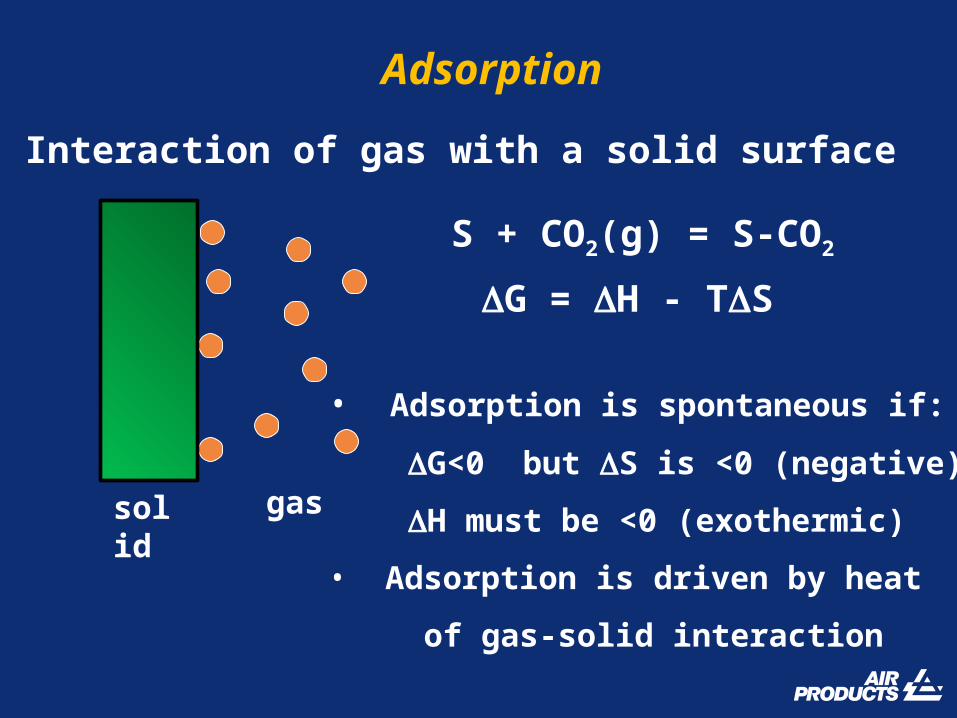
Adsorption
• Interaction of gas with a solid surface
solid gas
S + CO2(g) = S-CO2
G = H - TS
• Adsorption is spontaneous if:
G<0 but S is <0 (negative)
H must be <0 (exothermic)
• Adsorption is driven by heat
of gas-solid interaction

3
1. Physical adsorption (physisorption) - weak physical interactions -O=C=O
+
+
2. Chemical adsorption (chemisorption) - chemical bond formed
3. Bulk reaction: absorption - reaction at surface, diffusion into bulk
Types of Adsorption
O=C=O
OH
COH
O
O
=
CaO
CaCO3
CO2
4
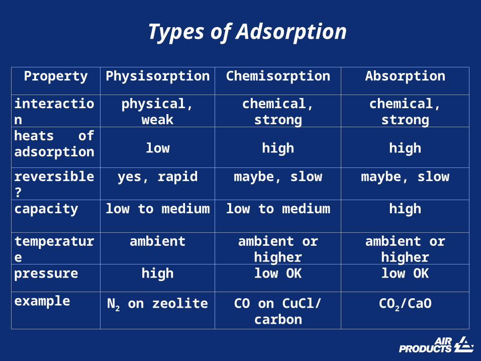
Types of Adsorption
Property Physisorption Chemisorption Absorption
interaction physical, weak chemical, strong chemical, strong
heats of adsorption low high high
reversible? yes, rapid maybe, slow maybe, slow
capacity low to medium low to medium high
temperature ambient ambient or higher ambient or higher
pressure high low OK low OK
example N2 on zeolite CO on CuCl/carbon
CO2/CaO

5
The adsorption process
adsorptionstep
desorptionstep
CO2
others
CO2,others

6
Pressure swing adsorption (PSA)
CO2 at P1
Adsorption Desorption
P1 > P2
CO2 at P2
• Feed exposure times are short (sec/min)• Modest working capacities• Best suited to bulk separation
purge
cap
ac
ity
gas partial pressure
P1P2
X1
X2
adsorption isotherm
7
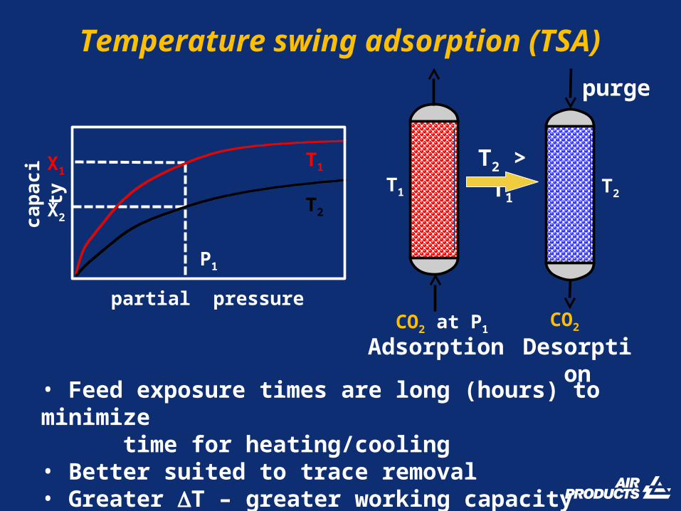
Temperature swing adsorption (TSA)
• Feed exposure times are long (hours) to minimize time for heating/cooling• Better suited to trace removal• Greater T – greater working capacity
CO2 at P1
T1 T2
Adsorption Desorption
T2 > T1
CO2
purge
X1
X2
cap
ac
ity T1
T2
P1
partial pressure
8
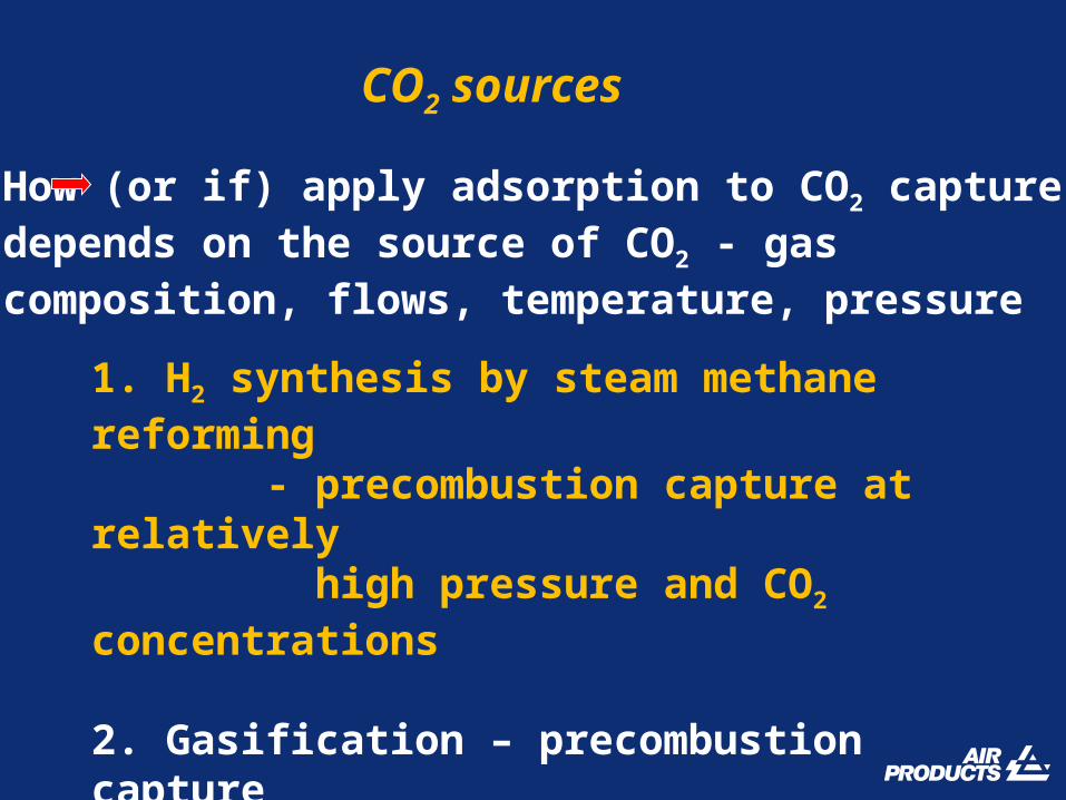
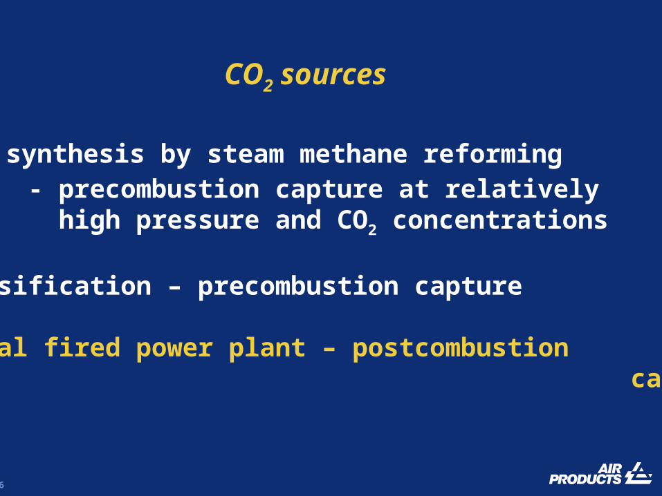
CO2 sources
1. H2 synthesis by steam methane reforming - precombustion capture at relatively high pressure and CO2 concentrations
2. Gasification – precombustion capture
3. Coal fired power plant – postcombustion capture
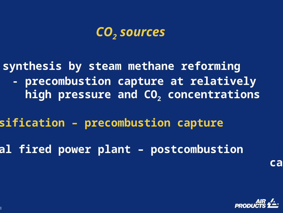
How (or if) apply adsorption to CO2 capturedepends on the source of CO2 - gascomposition, flows, temperature, pressure
9
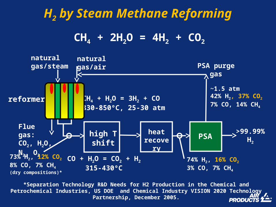
H2 by Steam Methane Reforming
PSAhigh Tshift
CO + H2O = CO2 + H2
315-430ºC
CH4 + H2O = 3H2 + CO830-850ºC, 25-30 atm
naturalgas/air
naturalgas/steam
heatrecovery
>99.99%H2
PSA purgegas
73% H2, 12% CO2
8% CO, 7% CH4
(dry compositions)*
74% H2, 16% CO2
3% CO, 7% CH4
CH4 + 2H2O = 4H2 + CO2
~1.5 atm42% H2, 37% CO2
7% CO, 14% CH4
Flue gas:CO2, H2O, N2, O2
*Separation Technology R&D Needs for H2 Production in the Chemical and Petrochemical Industries, US DOE and Chemical Industry VISION 2020 Technology Partnership, December 2005.
reformer
10
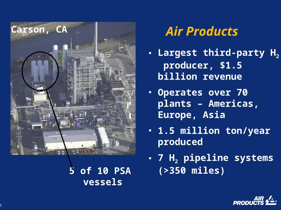
5 of 10 PSA vessels
• Largest third-party H2 producer, $1.5 billion revenue
• Operates over 70 plants – Americas, Europe, Asia
• 1.5 million ton/year produced
• 7 H2 pipeline systems (>350 miles)
Air ProductsCarson, CA

11
Tarragona, Spain
12
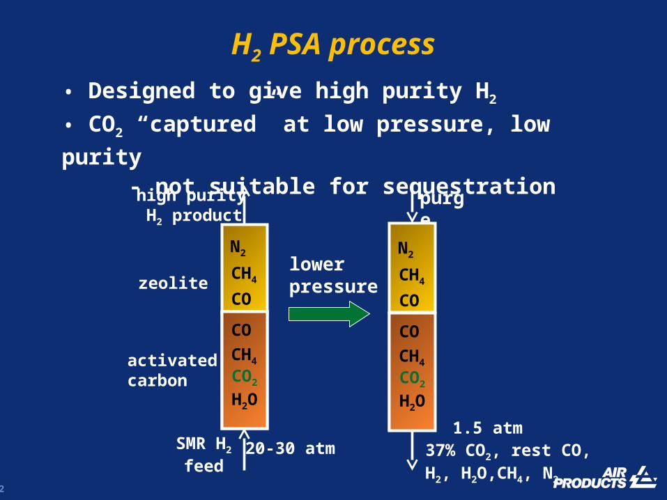
SMR H2
feed
high purity H2 product
activated carbon
zeolite
purge
lowerpressure
20-30 atm 37% CO2, rest CO, H2, H2O,CH4, N2
H2 PSA process
• Designed to give high purity H2
• CO2 “captured” at low pressure, low purity
- not suitable for sequestration
N2
CH4
CO
CO
CH4
CO2
H2O
N2
CH4
CO
CO
CH4
CO2
H2O
1.5 atm
13
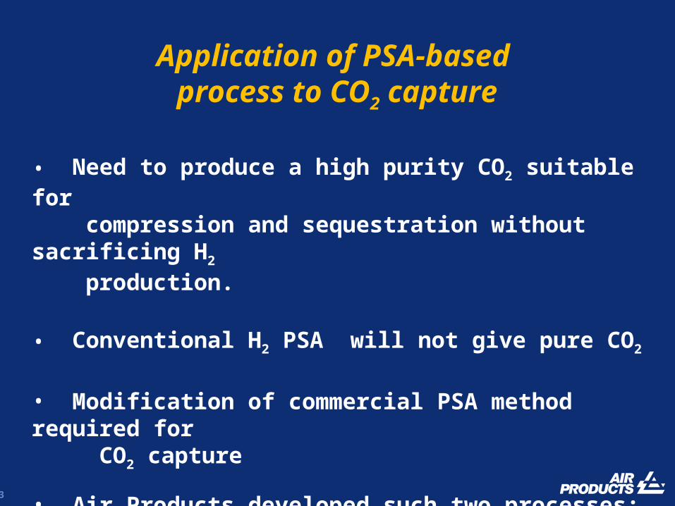
• Need to produce a high purity CO2 suitable for compression and sequestration without sacrificing H2 production.
• Conventional H2 PSA will not give pure CO2
• Modification of commercial PSA method required for CO2 capture
• Air Products developed such two processes: Gemini and CO2 VSA in 1980s – CO2 for urea market
Application of PSA-based process to CO2 capture
14
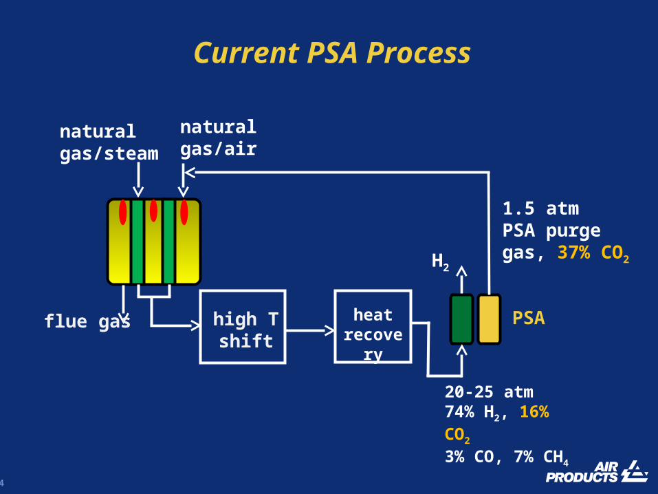
PSAhigh Tshift
naturalgas/air
naturalgas/steam
heatrecovery
H2
1.5 atmPSA purgegas, 37% CO2
Current PSA Process
flue gas
20-25 atm74% H2, 16% CO2
3% CO, 7% CH4
15
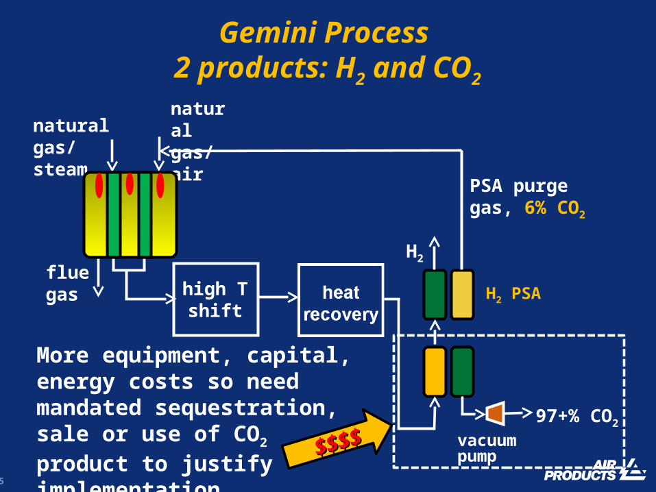
Gemini Process 2 products: H2 and CO2
H2 PSAfluegas
naturalgas/airnatural gas/
steam
H2
PSA purgegas, 6% CO2
97+% CO2
vacuumpump
More equipment, capital, energy costs so need mandated sequestration, sale or use of CO2 product to justify implementation
$$$$$$$$
high Tshift
16
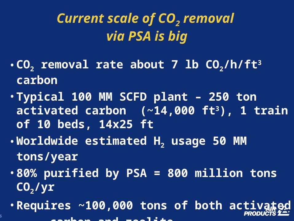
• CO2 removal rate about 7 lb CO2/h/ft3 carbon
• Typical 100 MM SCFD plant – 250 ton activated carbon (~14,000 ft3), 1 train of 10 beds, 14x25 ft
• Worldwide estimated H2 usage 50 MM tons/year
• 80% purified by PSA = 800 million tons CO2/yr
• Requires ~100,000 tons of both activated
carbon and zeolite
BUT…BUT…
Current scale of CO2 removal via PSA is big

17
• Very high flows and quantities of CO2
• A gasification plant requires 2,000 to 2,500 tons carbon adsorbent (>100,000 ft3), 10 trains of 10 beds! Coal-fired power plant still more
• Huge technical challenge
• Need higher capacities, faster cycles, or both• Are there nontraditionalnontraditional adsorption based
alternatives?• Numerous efforts in nontraditional adsorption
The scale of CO2 capture is immense
18
CO2 sources
1. H2 synthesis by steam methane reforming - precombustion capture at relatively high pressure and CO2 concentrations
2. Gasification – precombustion capture
3. Coal fired power plant – postcombustion capture

19
Precombustion capture: CO2 removal in gasification
Gasification
fuel
O2
H2O
CO2
RemovalCombustion
Turbine/generator
CO2
kW
H2O, minor CO2600 psi, 1340ºCmostly H2, CO, H2O CO2
H2, CO
air
• CO2 at high pressure, concentration, temperature• Capture is “easy”
• Ideally high T capture, high CO2 capacity, high H2
recovery• Adsorbent must be OK cycled at high T, high steam• The adsorbent is the key…
20
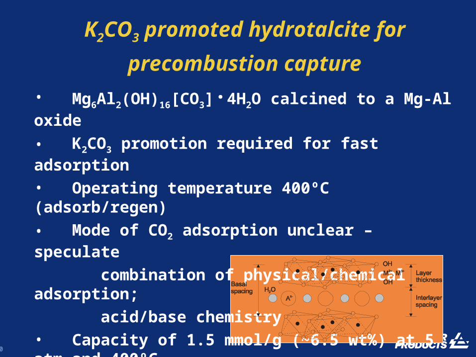
• Mg6Al2(OH)16[CO3]·4H2O calcined to a Mg-Al oxide
• K2CO3 promotion required for fast adsorption
• Operating temperature 400ºC (adsorb/regen)
• Mode of CO2 adsorption unclear – speculate
combination of physical/chemical adsorption;
acid/base chemistry• Capacity of 1.5 mmol/g (~6.5 wt%) at 5 atm and 400ºC• No negative impact of
steam on adsorption• Good cycling stability
K2CO3 promoted hydrotalcite for
precombustion capture

21
• WGS catalyst + high temperature CO2 adsorbent - HTC
• Removes CO2 from hot feed gas (400-500ºC), drives CO towards zero, increases conversion to H2
• Cyclic process - reaction/adsorption and regeneration
Sorption Enhanced Water Gas Shift Process
air
Gasification
fuel
O2
H2O
CO2 forcapture
57% H2, 16%CO10% CO2, 16% H2O
CombustionTurbine/
generator
kW
N2, H2O, <1% CO2
87% H2, 0.5%CO2% CO2, 8% H2O
WGS reaction: CO + H2O = CO2 + H2
WGS catalyst/HTC adsorbent
22
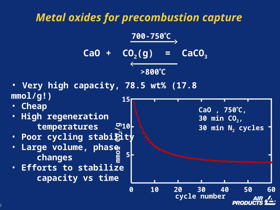
Metal oxides for precombustion capture
mm
ol
CO
2/g
CaO + CO2(g) = CaCO3
700-750C
>800C
• Very high capacity, 78.5 wt% (17.8 mmol/g!)• Cheap• High regeneration temperatures• Poor cycling stability• Large volume, phase changes • Efforts to stabilize capacity vs time
CaO , 750C, 30 min CO2, 30 min N2 cycles
5
10
15
0 10 20 30 40 50 60cycle number
23
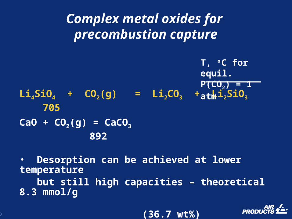
Complex metal oxides for precombustion capture
Li4SiO4 + CO2(g) = Li2CO3 + Li2SiO3 705
CaO + CO2(g) = CaCO3 892
• Desorption can be achieved at lower temperature but still high capacities – theoretical 8.3 mmol/g (36.7 wt%)
• A solid absorbent from Toshiba Corp has some very promising properties for precombustion CO2 capture
T, ºC for equil.P(CO2) = 1 atm

24
• Li4SiO4 with <10 mole% K2CO3; Li2TiO3 binder; 5 mm
spheres
• Very large capacity, 5.4 mmol/g, 650C, 1 atm CO2
• Fast absorption/desorption, fully reversible
• Excellent physical, cycling stability
• OK in the presence of steam
• Absorption chemistry (confirmed by XRD)
Li4SiO4 + CO2(g) = Li2CO3 + Li2SiO3
equil. P(CO2) = 0.15 atm at 650C
• K2CO3 lowers mp of Li2CO3 (723C) product; molten
phase improves absorption properties
Toshiba absorbent

25
Toshiba absorbent – TGA studies
650C
500C
Adsorption is very fast at 650C1 atm CO2
700C10 min CO2,10 min N2
• Excellent cycling stability inspite of large phase changes• No loss of crush strength or physical integrity
2.0
4.0
6.0
0 5 10 15 20 25 30
time, min
mm
ol
CO
2/g
4.0
4.5
5.0
5.5
0 10 20 30 40 50 60cycle number
mm
ol
CO
2/g
26
CO2 sources
1. H2 synthesis by steam methane reforming - precombustion capture at relatively high pressure and CO2 concentrations
2. Gasification – precombustion capture
3. Coal fired power plant – postcombustion capture
27
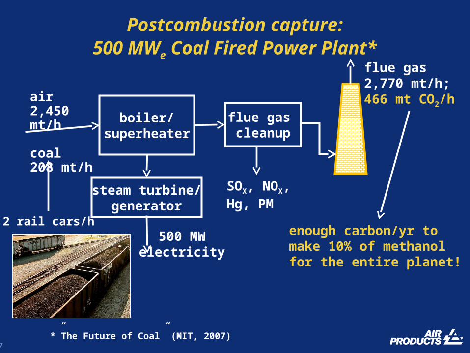
Postcombustion capture:500 MWe Coal Fired Power
Plant*
2 rail cars/henough carbon/yr to make 10% of methanolfor the entire planet!
air 2,450 mt/h
coal 208 mt/h
flue gas cleanup
flue gas2,770 mt/h;466 mt CO2/h
boiler/superheater
steam turbine/generator
500 MWelectricity
SOX, NOX,Hg, PM
*”The Future of Coal” (MIT, 2007)
28
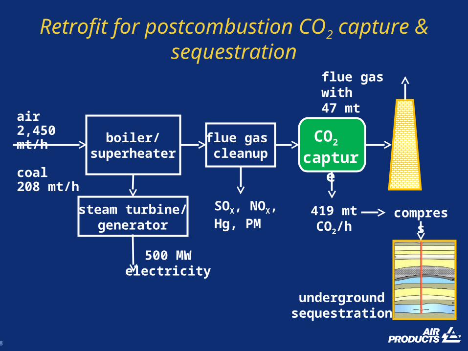
Retrofit for postcombustion CO2 capture & sequestration
flue gas with 47 mt CO2/h
CO2 capture
419 mt CO2/h
compress
undergroundsequestration
air 2,450 mt/h
coal 208 mt/h
flue gas cleanup
boiler/superheater
steam turbine/generator
500 MWelectricity
SOX, NOX,Hg, PM
29
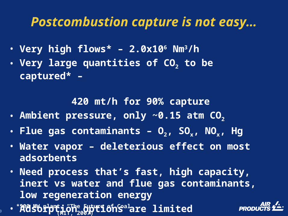
Postcombustion capture is not easy…
*500 MW plant, “The Future of Coal” (MIT, 2007)
• Very high flows* – 2.0x10⁶ Nm3/h
• Very large quantities of CO2 to be captured* –
420 mt/h for 90% capture
• Ambient pressure, only ~0.15 atm CO2
• Flue gas contaminants – O2, SOx, NOx, Hg
• Water vapor – deleterious effect on most adsorbents• Need process that’s fast, high capacity, inert vs water
and flue gas contaminants, low regeneration energy• Adsorption options are limited• May need a creative solution beyond conventional
fixed bed technology

30
Alkali carbonates forpostcombustion capture
K2CO3 + H2O(g) + CO2(g) = 2KHCO3
•Maximum capacity - 7.2 mmol/g (~32 wt%)•Infinite selectivity vs nonreactive gases•Absorb at 60ºC, regenerate at >150ºC
•Water required for CO2 adsorption
•High heats, 34.5 kcal/mol CO2
•Capture process
- difficult with fixed bed adsorption process
- likely need fluidized bed, “entrained bed reactor”

31
RTI Entrained Bed Reactor
• Bench scale demo: 50 lb Na2CO3, >90% capture, 2-10 lb CO2/h
Issues:- physical attrition- phase/volume changes- high SO2 affinity
32
Conclusions• Adsorption based CO2 capture from H2 plants is achievable but requires additional unit operations beyond currently existing ones. A driver for CO2 capture is required – mandated capture, sale or use of CO2 product.
• Larger scale capture such as gasification, power plants presents a significant challenge for an adsorption process.
• Nontraditional adsorbents and processes will likely be required, especially for postcombustion capture.


![Selective adsorption of carbon dioxide from mixed vapors by ......carbon, activated carbon, silicalite, C 186 schwarzite, and nanoporous carbon experimentally or theoretically [1 –9]](https://img.pdfslide.us/doc/110x75/60f7907564e7b45e607c574a/selective-adsorption-of-carbon-dioxide-from-mixed-vapors-by-carbon-activated.jpg)