Embed Size (px)
Citation preview

CARBON-BASED FIBROUS EDLC CAPACITORS AND
SUPERCAPACITORS
C.Lekakou, O.Moudam, F.Markoulidis, T.Andrews, J.F.Watts and G.T.Reed
Faculty of Engineering and Physical Sciences
University of Surrey
Guildford, Surrey GU2 7XH, UK
Email of corresponding author: [email protected]
Abstract
This paper investigates electrochemical double layer capacitors (EDLCs) including
two alternative types of carbon-based fibrous electrodes, a carbon fibre woven fabric
(CWF) and a multiwall carbon nanotube (CNT) electrode, as well as hybrid CWF-
CNT electrodes. Two types of separator membranes were also considered. An organic
gel electrolyte PEO-LiCIO4-EC-THF was used to maintain a high working voltage.
The capacitor cells were tested in cyclic voltametry, charge-discharge and impedance
tests. The best separator was a glass fibre-fine pore filter. The carbon woven fabric
electrode and the corresponding supercapacitor exhibited superior performance per
unit area, whereas the multiwall carbon nanotube electrode and corresponding
supercapacitor demonstrated excellent specific properties. The hybrid CWF-CNT
electrodes did not show a combined improved performance due to the lack of carbon
nanotube penetration into the carbon fibre fabric.

1. Introduction
There is much interest in electrochemical double layer capacitors (EDLCs) due to
the quick response and high mobility of the ions of the electrolyte and the increase
of energy storage due to the double capacitor layer effect. Carbon-based
electrodes attract a lot of research as they offer the possibility of a good conductor
of large surface area. Much research has focused on porous carbon electrodes [1-
5] which supply large surface area but are poor conductors, offering reduced
power density. The next step is to consider fibrous carbon materials [6] of good
conductivity to ensure high power density, whereas the high surface area of their
fibrous structure could provide good energy density. Such materials have the
advantage of having been considered and applied in the field of structural
composites from which there is a wealth of research and expertise on their
processing and their impregnation by viscous and viscoelastic fluids [7-9].
Furthermore, there is increased interest in fibrous materials and textiles for
wearable electronics for everyday use, biomedical monitoring and other specific
applications for which a wearable unit for energy storage and supply would be
most useful. As a result, it would be worthwhile to explore the use of carbon-
based fibrous materials as EDLC electrodes. Shirshova et al [10] tested high
conductivity, non-activated carbon fibre fabrics as electrodes for capacitor devices
with a polymer gel electrolyte, poly(ethylene glycol) diglycidyl ether (PEGDGE),
which resulted in very low capacitance, whereas their activated carbon fabrics had
high resistance.
Carbon nanotubes have the advantage of forming electrically conductive networks
and possibly being able to also store energy [11]. Pushparaj et al, 2007 [12] used

as electrode MWNTs aligned perpendicularly to the current collector and
embedded in cellulose, and they fabricated supercapacitors with a maximum
power density of 1.5 kW/kg for an RTIL electrolyte. Shi et al [13] reported that
growing carbon nanotubes directly on the nickel foam current collector lowered
the internal resistance. Ma et al [14] reported the inclusion of MWNTs in phenolic
resin mixtures and carbonisation of the mixture at 850 oC, which yielded
electrodes of a specific capacitance of 15-25 F/cm3
using 38 wt.% H2SO4 as
electrolyte. Binderless carbon or MWNT electrodes [15] have been considered
and they might have lower resistance in the absence of a polymeric binder while
they are also of lower cost. However, the results of Bordjica et al [15] cannot be
compared directly to the results of the present study, as they used mainly activated
carbon as their electrode and only a small percentage of MWNTs, and an aqueous
KOH electrolyte, whereas the present study uses non-activated fibrous carbon
electrodes and an organic electrolyte. Guo et al [16] found that if carbon
nanotubes embedded in electrospun carbon nanofibres (CNFs) doubled the
capacitance of CNFs using 1 M H2SO4 electrolyte.
The electrolyte is very important in the performance of a capacitor, and more
specifically the ion mobility and the electrochemical stability of the electrolyte
(defining the potential range of use of the electrolyte). Aqueous electrolytes have
low electrical resistance, high ion mobility but low maximum voltage around 1 V
[17]. This means that they are highly suitable for very low voltage applications
but for medium and high voltage applications assemblies of many in-series
connected low voltage cells are required for the capacitor bank. An in-series
connection of N cells with a cell capacitance C and a cell resistance R reduces the

total capacitance to C/N and increases the total resistance to NR. Hence, this study
has included an organic electrolyte with relatively high working voltage. Lithium
ion electrolytes have been used in both battery and capacitor applications. The
anion CIO4 has moderate binding ability with aprotic solvents [18]. The PMMA–
EC–PC–TEAClO4 gel electrolyte has a working potential range of -2.5 to +2.5 V
and exhibited a maximum capacitance of 3.7–5.4 mFcm−2
[19]. Polyethylene
oxide is an ionomer supplying anions [18], hence, it has been incorporated in the
gel electrolyte in this study. Furthermore, ion mobility in a porous electrode is
linked to the relative sizes of pores and ions [20]. In recent studies [21, 22],
TEABF4 is a popular organic electrolyte that can be used in cyclic voltametry up
to 3 V without any degradation; however, the size of TEA+ is rather large [20] in
comparison with the size of Li+
ions and ions of aqueous electrolytes, hence it was
decided to use a Li+ based organic electrolyte in this study. Further developments
on supercapacitors in latest studies are based on adding pseudocapacitance
compounds to the carbon fibrous electrodes [22, 23] which increase the overall
capacitance but introduce redox processes that would reduce the lifetime of the
capacitor device.
The present study considers the fabrication and testing of novel EDLC cells with
carbon-based fibrous electrodes without any binder, two different types of
separator membranes, and an organic gel electrolyte, PEO-LiCIO4-EC-THF. Two
different types of electrically conductive fibrous carbon material were explored as
electrodes on their own or as a combination: a carbon fibre plain woven fabric
(CWF) and multiwall carbon nanotubes (MWNTs). The purpose of the organic gel
electrolyte was a relatively high working voltage, fast moving small Li+ ions and

the fabrication of a homogeneous, compliant EDLC. The carbon fibre fabric
consisted of tows comprising many microfibres and resulting in a structure of dual
porosity including meso- and micro-pores. Impregnation of this fabric by a
viscous electrolyte would be channelled preferentially into the mesopores and
might leave unfilled micropores [24-25]. As a result, care was taken during the
fabrication to perform impregnation slowly and for a long time to ensure
maximum impregnation of microspores. In the case of MWNTs, dispersion was
very important to achieve maximum surface area and maximum number of
conductive paths in the MWNT network. Two types of separator membranes were
used alternatively: a filter membrane with 0.8 m pores, and a glass microfibre
filter (GF/F) with 0.7 m average pore size. All EDLC cells were tested in cyclic
voltametry, charge-discharge, and impedance tests. Two EDLC cells exhibited
excellent performance: the CWF-GF/F cell demonstrated excellent performance
per unit area, and the CNT-GF/F cell demonstrated excellent specific properties
(per unit mass).
2. Materials
2.1 Carbon fibre plain woven fabric electrodes
An engineering carbon fibre fabric was used of plain weave, A0186, from
Folthergill Engineered Fabrics, of a nominal thickness of 270 m and areal
density of 19.9 mg/cm2. The carbon fabric was used as received and the carbon
was not activated in any way.

2.2 Carbon nanotube (CNT) electrodes
Multiwall carbon nanotubes (MWNT) ElicarbMW®
from Thomas Swan Ltd were
used, with the following parameters: outer diameter of 10-30 nm, tens of microns
length, and >92% purity. In a previous dielectrophoresis study in Araldite epoxy
by our group [26], it was determined that they have high electrophoretic mobility
= 0.0025 m mm/Vs and zeta potential of 67 mV.
In this study, 0.3% w/v MWNTs were dispersed in THF first via sonication for 1
hr and afterwards via high shear mixing at 18,000 rpm for 1 hr. The mixture was
deposited with a syringe drop-by-drop onto an aluminium tape current collector.
THF was allowed to evaporate and a thin MWNT mat was formed.
2.3 Separator
Two types of separators were tried:
Supor® poly(estersulphone) filter membrane by PALL: 0.8 µm pores, measured
thickness of 290 µm.
GF/F filter, a glass microfibre filter by Whatman with 0.7 µm average pore size
and a nominal thickness of 420 µm.
2.4 Electrolyte
The electrolyte was a PEO-LiClO4-EC-THF organic gel electrolyte consisting of
0.5 g polyethylene oxide (PEO, Mv=100,000, nd=1.45), 0.21 g LiClO4 and 0.29 g
ethylene carbonate (EC) in 10 ml THF. All substances were purchased from
Sigma Aldrich. Processing of the electrolyte was carried out after gently heating it
as EC solidifies at 35 oC.

3. Experimental methods
3.1 Fabrication of capacitor cells
Fig.1. Diagrams of EDLC cells fabricated and tested in this study
Al PEO/EC/LiClO4
PEO/EC/LiClO4
Carbon fibre fabric/CNT
Carbon fibre fabric/CNT membrane
Al PEO/EC/LiClO4
PEO/EC/LiClO4
Carbon fibre fabric
Carbon fibre fabric membrane
CNT
CNT
PEO/EC/LiClO4
PEO/EC/LiClO4
membrane
Al

Fig.1 presents the EDLC capacitor cells fabricated and tested in this study. In each
case, the separator porous membrane was dip-coated in the electrolyte gel,
sandwiched between the electrodes, and the whole cell was sealed under gradually
increasing pressure up to 5 kPa. Generally, each carbon fibre woven fabric based
capacitor cell was 2 cm2 and each CNT-based capacitor cell was 1 cm
2.
The following types of capacitor cells were fabricated and tested:
(i) Carbon fibre woven fabric electrodes and GF/F filter separator (CFW-
GF/F)
(ii) Carbon fibre woven fabric electrodes and Supor® filter separator (CFW-
Supor)
(iii) Carbon nanotube electrodes and GF/F filter separator (CNT-GF/F)
(iv) Carbon nanotube electrodes and Supor® filter separator (CNT-Supor)
(v) Hybrid CFW-CNT electrodes and GF/F filter separator (CFW-CNT-GF/F)
(vi) Hybrid CFW-CNT electrodes and Supor®
filter separator (CFW-CNT-
Supor)
3.2 Testing of the capacitor cells
The fabricated capacitor cells were tested using a VersaSTAT4 Electrochemical
System in cyclic voltametry, charge-discharge, and impedance tests. Cyclic
voltametry (CV) was performed initially within 0 to +3V to find the maximum
breakdown potential of the electrolyte and subsequently within 0 to 2.5 V. The
area of the I-V envelope gave the power, P, and power density, Psp, of the full

capacitor cell (by dividing by the mass of the two carbon-based electrodes).
Considering the current at the mid-point, Im, and the scan rate, dV/dt, the
capacitance, CCV, was determined:
dtdV
IC m
CV/
(1)
Charge-discharge tests were also used to determine capacitance:
dtdV
ICCD
/ (2)
while impedance, Z, testing provided more data of the capacitance as function of
frequency, f (angular frequency = 2f), where
ZjZZ (3),
the real part of impedance Z’ is the resistance R, the imaginary part of impedance,
Z’’, is the sum of the capacitive reactance Xc (depending on capacitance C) and
the inductive reactance XL (depending on inductance L):
CXC
1 (4)
LX L (5)
The maximum energy Emax stored in the capacitor is given by

2
maxmax2
1CVE (6)
The maximum power of the capacitor Pmax depends on its equivalent-series-
resistance ESR according to the relation, where ESR values in this study included
both electrolyte and interface resistances.
ESR
VP
4
2
max (7)
4. Results
4.1 Carbon fibre woven fabric (CFW) based capacitors
Fig.2. Cyclic voltametry of EDLC CWF-GF/F capacitor from 0 to 2.5 V at a rate
of 0.15 V/s and specific capacitance of electrode; each carbon electrode has an
area of 2 cm2 and mass of 40 mg.
-0.02
-0.01
0
0.01
0.02
0.03
0.04
0.05
0 0.5 1 1.5 2 2.5 3
Potential (V)
Cu
rre
nt (A
)
-8
-6
-4
-2
0
2
4
6
8
10
12
14
0 0.5 1 1.5 2 2.5 3
Potential (V)
Csp
(F
/g)

Fig.2 presents the results from cyclic voltametry for the CWF based electrode
capacitors with a GF/F filter as separator. From the plots, a maximum potential of
2.3 V may be considered for the electrolyte of LiClO4/EC/PEO, which is higher
than previously reported (1 V for [27] using LiClO4/EC/PC/Polyurethane
electrolyte) for similar electrolytes in a carbon cloth electrode, demonstrating the
excellent pairing of the electrolyte and the CWF electrode in this study. In fact,
the present study has reached the highest possible potential for LiClO4, where
beyond this, electrolyte breakdown occurs.
-2.5
-2
-1.5
-1
-0.5
0
0.5
1
1.5
2
2.5
0 20 40 60 80 100 120
Time (s)
Po
ten
tial
(V)
Fig.3. Charge-discharge testing of EDLC CWF-GF/F capacitor at constant current
steps of -5 mA and +5 mA ; each carbon electrode has an area of 1 cm2 and mass
of 20 mg.
Fig.3 presents the results of the charge-discharge test from which the electrode
capacitance has been determined as CDischarge,max = 0.076 F/cm2 or 3.81 F/g. This
yields the corresponding energy E = 0.20 J/cm2 and Esp = 2.8 Wh/kg.
0
2
4
6
8
10
12
14
16
0 5 10 15
Z'(ohm)
Z''(
oh
m)
Fig.4. Nyquist plot from impedance testing of EDLC CWF-GF/F capacitor
between 10 kHz and 1 Hz; each carbon electrode has an area of 2 cm2 and mass of
40 mg.
1.E-08
1.E-07
1.E-06
1.E-05
1.E-04
1.E-03
1.E-02
0 2000 4000 6000 8000 10000 12000
Frequency (Hz)
Ca
pa
cita
nce
(F
)
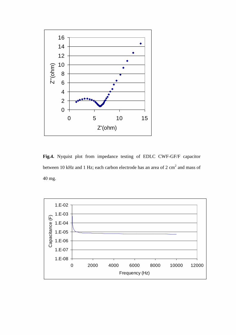
Fig.5. Capacitance as a function of frequency from impedance testing of EDLC
CWF-GF/F capacitor between 10 kHz and 1 Hz; each carbon electrode has an area
of 2 cm2 and mass of 40 mg.
Fig.4 displays the Nyquist plot from the impedance testing of an EDLC CWF-
GF/F capacitor, which displays an ESR of 6.1 ohm, yielding a maximum power
density for the EDLC cell of 2.7 kW/kg. Fig.5 presents the AC capacitance of the
EDLC CWF-GF/F cell as a function of AC frequency, showing that there is a
large fall of capacitance of two orders of magnitude within the first 500 Hz,
thereafter the capacitance falls much more slowly. In general, the results of
capacitance, power density and energy density for the EDLC CWF-GF/F
electrode and capacitor cell demonstrate that its performance is higher than other
fibre fabric capacitors reported in the literature (e.g. several orders of magnitude
better than Shirshova et al’s work [10]) and that it is at the levels of current
commercial supercapacitors..
The same experiments were repeated using as separator the thinner Supor®
poly(estersulphone) filter membrane. The main performance results are presented
in Table 1. It is clear that the EDLC CWF-Supor cell is inferior in both ESR and
capacitance, yielding much lower power and energy densities. It is thought that
the reason for this is the large surface area of the microfiber GF/F filter separator
and its large absorbance of the electrolyte, which lowers ESR while it also
increases capacitance. These good properties of the glass fibre papers have also
been observed by other investigators with different electrolytes (e.g. Staiti et al
[28] with H2SO4 as electrolyte).

Table 1. Summary of performance results of the various types of electrodes combined
with two different types of separators
(PCV: power from cyclic voltametry 0 to 2.5 V at 0.2 V/s. PCV,sp: power density from
cyclic voltametry at 0.2 V/s. Pmax: maximum power on the basis of the ESR
determined from the impedance test. Pmax,sp: maximum power density. Emax:
maximum energy. Emax,sp: maximum energy density)
Cell: CFW-
GF/F
CFW-
Supor
CNT-GF/F CNT-
Supor
CFW-
CNT-
GF/F
CFW-
CNT-
Supor
PCV (W/cm2) 0.0350.15V/s 0.012 0.004 0.004 0.004 0.006
PCV,sp
(kW/kg)
1.7680.15V/s 0.320 20 1.84 0.245 0.265
Pmax (W/cm2) 0.207 0.012 0.011 0.024 0.01 0.014
Pmax,sp
(kW/kg)
10.4 0.292 113 12.1 0.52 0.60
CCV (F/cm2) 0.080.15V/s 0.015 0.002 0.008 0.053 0.008
CCV,sp (F/g) 3.780.15V/s 0.095 12.487 5.2 2.6 0.38
CD (F/cm2) 0.085mA/cm
2 No test 0.00120A/cm2 No test No test No test
CD,sp (F/g) 3.815mA/cm2 No test 6.3920A/cm
2 No test No test No test
E (J/cm2) 0.200.15V/s 0.040 0.007 0.02 0.085 0.013
Emax,sp
(Wh/kg)
2.800.15V/s 0.280 9.2 2.94 1.17 0.164

4.2 Carbon nanotube (CNT) based capacitors
-0.0008
-0.0006
-0.0004
-0.0002
0
0.0002
0.0004
0.0006
0.0008
-3 -2 -1 0 1 2 3
Potential (V)
Cu
rre
nt (A
)
Fig.6. Cyclic voltametry of EDLC CNT-GF/F capacitor from 0 to 2.5 V at a rate
of 0.2 V/s and specific capacitance of electrode; each CNT electrode has an area
of 1 cm2 and mass of 0.2 mg.
First, EDLC cells were fabricated with CNT electrodes (deposited on Al current
collectors) and a GF/F filter separator. The cells were subjected to cyclic
voltametry, charge-discharge, and impedance tests. Fig.6 presents the results from
cyclic voltametry plotted as current versus potential, and capacitance versus
potential graphs. From the graphs, a maximum potential of 2.3 V may be
considered for the electrolyte of LiClO4/EC/PEO, same as for the CWF electrodes.
The I-V curves display a bump at -1.1 and + 1.1 V, indicating redox reactions at
the CNTs. The first results show clearly that the areal power and capacitance (per
cm2) are lower than the corresponding properties of the CWF-GF/F cell (see Table
1) but the CNT-GF/F cell has much higher specific properties, such as power
density, Psp, and specific capacitance, Csp, due to the very small mass of each CNT
electrode.
-40
-30
-20
-10
0
10
20
30
40
-3 -2 -1 0 1 2 3
Potential (V)
Ca
pa
cita
nce
(F
/g)

0
0.2
0.4
0.6
0.8
1
1.2
0 100 200 300 400 500
Time (s)
Po
ten
tia
l (V
)
Fig.7. Charge-discharge testing of EDLC CNT-GF/F capacitor at constant current
steps of -20 A and +20 m ; each carbon electrode has an area of 1 cm2 and mass
of 0.2 mg.
Fig.7 presents the results of the charge-discharge test from which the capacitance
has been determined as CDischarge,max = 0.0013 F/cm2 or 6.39 F/g. This yields the
corresponding energy E = 3.4 mJ/cm2
and Esp = 4.7 Wh/kg with excellent
charge/discharge energy efficiency at 97%.

0
100
200
300
400
500
600
0 200 400 600 800 1000
Z' (ohm)
Z''
(ohm
)
Fig.8. Nyquist plot from impedance testing of EDLC CNT-GF/F capacitor
between 100 kHz and 0.1 Hz; each carbon electrode has an area of 1 cm2 and
mass of 0.2 mg.
1.E-08
1.E-07
1.E-06
1.E-05
1.E-04
1.E-03
1.E-02
0 20000 40000 60000 80000 100000 120000
Frequency (Hz)
Ca
pa
cita
nce
(F
)
Fig.9. Capacitance as a function of frequency from impedance testing of EDLC
CNT-GF/F capacitor cell between 100 kHz and 0.02 Hz; each carbon electrode
has an area of 1 cm2 and mass of 0.2 mg.

Fig.8 displays the Nyquist plot from the impedance testing of an EDLC CNT-
GF/F capacitor cell, which displays clear supercapacitor behaviour with an ESR of
0.5 ohm, yielding a maximum power density of 28.3 kW/kg for the full cell. Fig.9
presents the AC capacitance of the full EDLC cell as a function of AC frequency.
It is evident that the EDLC CNT-GF/F cells behave as supercapacitors, as far as
power and energy densities are concerned, and they have an energy density of 2.3
Wh/kg.
When the Supor®
filter is used as a separator, the EDLC CNT-Supor cells (each
electrode: 1 cm2
and 2 mg) display much worse performance than the EDLC
CNT-GF/F cells, in a similar way as the EDLC carbon woven fabric based cells
(see Table 1).
4.3 Hybrid carbon woven fabric-carbon nanotube (CWF-CNT) based capacitors
-0.015
-0.01
-0.005
0
0.005
0.01
0.015
0.02
0.025
-3 -2 -1 0 1 2 3
Potential (V)
Cu
rre
nt (A
)
Fig.10. Cyclic voltametry of EDLC CWF-CNT-GF/F capacitor from -2.5 to 2.5 V
at a rate of 0.2 V/s and specific capacitance of electrode; each carbon electrode
has an area of 1 cm2 and mass of 20.2 mg (20 mg CWF and 0.2 mg CNTs).
-10
-5
0
5
10
-3 -2 -1 0 1 2 3
Potential (V)
Ca
pa
cita
nce
(F
/g)

-20
-10
0
10
20
30
40
50
0 100 200 300 400 500
Z' (ohm)
Z''
(oh
m)
Fig.11. Nyquist plot from impedance testing of EDLC CFW-CNT-GF/F capacitor
between 1 MHz and 0.03 Hz; each carbon electrode has an area of 1 cm2 and mass
of 20.2 mg.
Fig.10 presents cyclic voltametry results for the CFW-CNT-GF/F cell, which clearly
exhibits very low power and a maximum potential of 1.8 V. The low performance of
the cell is repeated also in the Nyquist plot in Fig.11, where it is evident that the cell
has several interface resistances, because of multiple types of interfaces of carbon
fabric and CNTs, due to the poor penetration of CNTs in CFW. Furthermore, even in
the low frequency region, there is very high loss and consequently current loss.
The EDLC CWF-CNT-Supor cells also showed a maximum operating potential of
only 1.8 V and exhibited an ESR of 118 ohm, yielding Pmax = 0.014 W/cm2 and Pmax,sp
= 0.60 kW/kg. The addition of MWNTs to the carbon fibre electrode did not yield any

considerable improvements with the Supor® filter as separator (CWF-CNT-Supor) in
the fabricated EDLC cells. The cells exhibited capacitance similar to that of the
CNT-Supor cells but with a lower maximum potential of 1.8 V which would decrease
both power and energy. Furthermore, the mass of electrodes includes the large mass
of the carbon fibre fabric without it contributing really to the capacitance; as a result,
the specific properties and energy density are reduced. However, the addition of
MWNTs reduces the ESR, increasing Pmax (even with lower maximum working
potential) and the power density.
1.E-05
1.E-04
1.E-03
1.E-02
1.E-01
1.E+00
1.E+01
1.E+02
1.E-05 1.E-03 1.E-01 1.E+01
Energy density (Wh/kg)
Po
we
r d
en
sity (
kW
/kg
)
CWF-GF/F
CNT-GF/F
Fig.12. Ragone plots of two types of EDLC supercapacitors (full cells): the CWF-
GF/F supercapacitor cell and the CNT-GF/F supercapacitor cell.
5. Conclusions
EDLC cells were fabricated with carbon-based fibrous electrodes. Two types of
separator membranes were tried: a Supor®
poly(estersulphone) microporous
membrane and a GF/F glass microfibre filter. The GF/F separator proved most
successful and its high performance in the EDLC cells could be attributed to the large
surface area of its microfibrous material. A PEO-LiCIO4-EC-THF gel electrolyte was
used that exhibited high maximum voltage of ±2.3 V for the CWF and CNT
electrodes, although some small bumps were present in the cyclic voltametry tests of
the CNT electrodes at ±1.1 V indicating redox reactions. The best types of EDLC
cells were the CWF-GF/F cells which demonstrated superior capacitance, energy and
power per unit area (per cm2), and the CNT-GF/F cells which demonstrated excellent
specific capacitance, power density and energy density. Data for these two best cells
were assembled into the Ragone plots presented in Fig.12. The MWNT electrode has
excellent specific properties but, due to its low density, a large area of electrode needs
to be coated to achieve the same area-based performance of a carbon fabric EDLC.
On the other hand, a carbon fibre fabric can be readily used as electrode or part of it
can be used for a wearable capacitor in wearable or fitted capacitor devices.
Another idea to add a very small amount of MWNTs to increase the surface area of
the fabric did not yield fruitful results due to the poor penetration of CNTs into the
microfibre fabric. In this case, the area properties of the hybrid electrode were the
same as or better than those of the CNT electrode but the maximum voltage fell to
1.8V.
Acknowledgments
The authors would like to gratefully acknowledge the funding of this project by
IeMRC/EPSRC UK, in the form of a research grant for which Dr O. Moudam was
employed as a research fellow.

References
1. C. Arbizzani, M. Mastragostino, F. Soavi “New trends inelectrochemical
supercapacitors,”, J. of Power Sources 10, 2001, 164-170
2. M. Kodama, J. Yamashita, Y. Soneda, H. Hatori, S. Nishimura, K. Kamegawa
“Structural characterization and electric double layer capacitance of template
carbons”, Materials Science and Engineering B108, 2004, 156-161.
3. D. Hulicova, M. Kodama, and H. Hatori “Electrochemical performances of
nitrogen-enriched carbons in aqueous and non-aqueous supercapacitors”,
Chem. Mater.18(9), 2006, 2318-2326
4. D. Tashima, K. Kurosawatsu, M. Otsubo, C. Honda “Surface Modification of
Carbon Electrode for Electric Double Layer Capacitor”, Plasma Processes and
Polymers, 4(S1), 2007, S502-S506.
5. E. G. Bushueva, P. S. Galkin, A. V. Okotrub, L. G. Bulusheva, N. N. Gavrilov,
V. L. Kuznetsov, and S. I. Moiseekov “Double layer supercapacitor properties
of onion-like carbon materials”, Phys. Stat. Sol (b), 245(10), 2008, 2296-2299
6. A.Nishino “Capacitors: operating principles, current market and technical
trends”, Journal of Power Sources 60 ( 1996) 137-147
7. E.Heardman, C.Lekakou and M.G.Bader, “Flow monitoring and permeability
measurement under constant and transient flow conditions”, Composites
Science and Technology, 64(9), 2004,1239-1249
8. S.Amico and C.Lekakou “An experimental study of the permeability and
capillary pressure in resin-transfer moulding”, Composites Science and
Technology, 61 (13), 2001, 1945-1959

9. E.Heardman, C.Lekakou and M.G.Bader “In-plane permeability of sheared
fabrics”, Composites A, 32 (7), 2001, 933-940
10. N. Shirshova, E. Greenhalgh, M. Shaffer, J. H. G. Steinke, P. Curtis, A.
Bismarck, Proc. ICCM17, Edinburgh, 2009
11. E.Frackowiaka and F.Beguin “Carbon materials for the electrochemical
storage of energy in capacitors”, Carbon, 39, 2001, 937–950
12. V.L.Pushparaj, M.M.Shaijumon, A.Kumar, S.Murugesan, L.Ci, R.Vajtai, R.J.
Linhardt, O.Nalamasu, and P.M.Ajayan “Flexible energy storage devices
based on nanocomposite paper”, PNAS, 104(34), 2007, 13574–13577
13. R.Shi, L.Jiang and C.Pan “A single-step process for preparing supercapacitor
electrodes from carbon nanotubes”, Soft Nanoscience Letters, 1(1), 2011, 11-
15
14. R.Z. Ma, J. Liang, B.Q. Wei, B. Zhang, C.L. Xu and D.H. Wu “Study of
electrochemical capacitors utilizing carbon nanotube electrodes”, Journal of
Power Sources 84, 1999, 126–129
15. T.Bordjiba, M.Mohamedi, L.H.Dao “Synthesis and electrochemical
capacitance of binderless nanocomposite electrodes formed by dispersion of
carbon nanotubes and carbon aerogels”, Journal of Power Sources, 172, 2007,
991–998
16. Q.Guo, X.Zhou, X.Li, S.Chen, A.Seema, A.Greiner and H.Hou
“Supercapacitors based on hybrid carbon nanofibers containing multiwalled
carbon nanotubes”, J. Materials Chemistry, 19, 2009, 2810-2816
17. R.Kotz, M. Carlen “Principles and applications of electrochemical capacitors”,
Electrochimica Acta, 45, 2000, 2483–2498

18. A. K. Shukla, S. Sampath and K. Vijayamohanan “Energy storage beyond
batteries”, Current Science, 79(12), 2000,1656-1661
19. S.A. Hashmi, S.Suematsu, K.Naoi “All solid-state redox supercapacitors based
on supramolecular 1,5 diaminoanthraquinone oligomeric electrode and
polymeric electrolytes”, J.Power Sources, 137, 2004, 145-151
20. J.Huang, B.G.Sumpter, and V.Meunier “A Universal Model for Nanoporous
Carbon Supercapacitors Applicable to Diverse Pore Regimes, Carbon
Materials, and Electrolytes”, Chem. Eur. J., 2008, 14, 6614 – 6626.
21. K.Hung, C.Masarapu, T.Ko and B.Wei “Wide-temperature range operation
supercapacitors from nanostructured activated carbon fabric”, J. of Power
Sources, 193(2), 2009, 944-949
22. C.Lei, P.Wilson and C.Lekakou “Effect of PEDOT in carbon-based composite
electrodes for electrochemical supercapacitors”, to be published in J.of Power
Sources
23. Z.Algharaibeh and P.G.Pickup “An asymmetric supercapacitor with
anthraquinone and dihydroxybenzene modified carbon fabric electrodes”,
Electrochemistry Comms, 13, 2011, 147-149
24. S.Amico and C.Lekakou “Flow through a two-scale porosity, oriented fibre
porous medium”, Transport in Porous Media, 54(1), 2004, pp.35-53
25. S.Amico and C.Lekakou “Mathematical modelling of capillary micro-flow
through woven fabrics”, Composites A, 31(12), 2000, pp.1331-1344
26. A.K.Murugesh, A.Uthayanan and C.Lekakou, Applied Physics A, 2010,
proofs completed, in press.

27. R.J.Latham, S.E.Rowlands and S.W.Schlindwein “Supercapacitors using
polymer electrolytes based on poly(urethane)”, Solid State Ionics, 147, 2002,
243-248
28. P. Staiti, M. Minutoli, F. Lufrano “All solid electric double layer capacitors
based on Nafion ionomer”, Electrochimica Acta 47(17), 2002, 2795-2800