Embed Size (px)
Citation preview
Zakłady Sprzętu Precyzyjnego “Niewiadów” S.A. [Ltd.] Osiedle Niewiadów 49 97-225 Ujazd, Poland tel. (0-44) 719-20-00 fax. (0-44) 719-20-16
e-mail: [email protected]
U S E R ’ S M A N U A L
C A R A V A N
T Y P E S : N 1 2 6 n , N 1 2 6 n t
Z a k ł a d y S p r z ę t u P r e c y z y j n e g o “ N i e w i a d ó w ” S . A . [ L t d . ]
9 7 - 2 2 5 U j a z d O s i e d l e N i e w i a d ó w 4 9
t e l . ( 0 - 4 4 ) 7 1 9 - 2 0 - 0 0 f a x . ( 0 - 4 4 ) 7 1 9 - 2 0 - 1 6
e - m a i l : e x p o r t @ n i e w i a d o w . p l
May 2006
1. INTRODUCTION Thank you for buying our caravan, manufactured at Trailer Production Plant
“Niewiadów” Sp. z o.o. [Ltd.]
Our more than 30 years of experience allows us to offer you this durable and safe product.
Before you start using the caravan, please thoroughly read this Manual and observe all guidelines provided herein. Failure to follow the instructions when using the caravan will result in loss of warranty.
Striving after continuous quality improvement of our products, we reserve the right to introduce any modifications due to current modernisations, which are not contained in this Manual.
We will be grateful if you send us your comments and observations made during operation of the caravan.
Being sure of your satisfaction when using our product, we wish you a safe journey.
Trailer Production Plant “NIEWIADÓW” Sp. z o.o. [Ltd.]
Furniture Wash the cooker and sink using water with a washing detergent and wipe to dry. Do not use any agents that may scratch the surfaces or cause chemical damage. Floor Wash the floor using hot water with washing agents added. Occasionally wax the floor with wax floor polish or other floor maintenance agents. Do the following after each season:
- wash the caravan shell with car shampoo, - check the condition of seals at all elements fixed to the caravan (aluminium strips, manoeuvre handles, lamps, windows) – make up any sealant losses with silicone or MS-type sealant, - protect connecting plug contacts with an agent for temporary protection (e.g. WD40), - spread a layer of protective car wax on the caravan’s shell surface.
8. INFORMATION ON THE ENVIRONMENTALLY SAFE USE AND UTILISATION OF
THE VEHICLE Caravans manufactured by Trailer Production Plant “Niewiadów” Sp. z o.o. are made of many materials. They contain plastics. We recommend that all repairs except minor ones, as described in this Manual, be done at Authorised Service Stations or specialised service stations. When the caravan reaches the end of its service life, take it to a licensed vehicle utilisation company.
1 26
TABLE OF CONTENTS
1. INTRODUCTION ...............................................................................1 2. TECHNICAL DATA ............................................................................2 3. EQUIPMENT .....................................................................................2 3.1. BASIC EQUIPMENT..........................................................................2 3.2. INTERIOR LAYOUTS........................................................................3 3.3. ACCESSORY EQUIPMENT..............................................................5 4. CARAVAN OPERATION ...................................................................5 4.1. HOOKING UP....................................................................................5 4.2. LOADING...........................................................................................6 4.3. BEFORE DRIVING............................................................................6 4.4. DRIVING............................................................................................7 4.5. UNHOOKING.....................................................................................7 5. OPERATION, SERVICING, CHASSIS MAINTENANCE ..................8 5.1. GENERAL INFORMATION ...............................................................8 5.2. BALL-TYPE COUPLING....................................................................8 5.3. SUSPENSION AND WHEEL BEARINGS.........................................9 5.4 DRIVING WHEELS............................................................................9 5.5. BRAKING SYSTEM.........................................................................10 5.6. SUPPORT (JOCKEY) WHEEL........................................................11 5.7. SIGNALLING SYSTEM ...................................................................12 6. CARAVAN BODY ............................................................................14 6.1 KITCHEN SET .................................................................................14 6.2 REFRIGERATING UNIT..................................................................15 6.3 INTERIOR HEATING.......................................................................15 6.4 PLACE TO SEAT AND SLEEP .......................................................15 6.5 INTERNAL SYSTEMS.....................................................................16 6.5.1 12V WIRING SYSTEM ....................................................................16 6.5.2 230V WIRING SYSTEM ..................................................................21 6.5.3 GAS SYSTEM .................................................................................22 6.5.3.1 GAS BOTTLE FITTING ...................................................................23 6.5.4 WATER SYSTEM............................................................................25 6.5.5 MOBILE TOILET..............................................................................25 7. CARAVAN BODY MAINTENANCE.................................................25 8. INFORMATION ON VEHICLE ENVIRONMENTALLY SAFE USE AND UTILISATION..........................................................................26
- in cases where an injured person looses consciousness and has stopped breathing, perform mouth-to-mouth resuscitation until a doctor arrives.
Every two years check the gas system to ensure it is tightly sealed and that all the valves are working correctly.
6.5.4. WATER SYSTEM
The water system consists of the following elements:
- lines supplying water - 10-litre tanks - water discharge line - tap with electro-valve - electric pump - output 12l/min
The water tanks are located in the kitchen cupboard (in the case of N126n), or in the bathroom cupboard (in the case of N126nt). The pump shall be installed in the water tank. Water flows out of the tap when the valve is turned on (the pump activates automatically). Sewage water is removed through a water piping system under the caravan. It is recommended to position the caravan at camping grounds directly over a drain, in order to prevent water from being spilled around the unit. 6.5.5. MOBILE TOILET Optionally, it is possible to equip the N126nt caravans with mobile toilets. A toilet like this possesses a tank accessible from the outside through a special door. Detailed descriptions regarding mobile toilet maintenance and operation are provided in an additional manual (accessory equipment). 7. CARAVAN BODY MAINTENANCE Shell and windows Body maintenance basically involves keeping it clean. It is possible to protect the laminate against dirt absorption with car body wax preparations and cleaning the surface when wet; it is best to use special agents for cleaning these preparations. To protect them from scratching, clean windows with a soft cloth and wash with plenty of water. Carpets and wall lining Clean wall lining with agents for carpet cleaning or other similar products. Wash mattress covers and curtains using washing detergents.
2. TECHNICAL DATA
Length 4500 mm Total width 2050 mm Total height 2550 mm Body length 3050 mm Inside body width 1960 mm Inside body height 1815 mm Wheel track 1500 mm Own weight - N126n - N126nt
560 kg 625 kg
Acceptable total weight 750 kg Number of places to sleep - N126n - N126nt
3 (4*)
2 Size of places to sleep - front: N126n, N126nt - back: N126n
1930x1300 (mm)
1930x650 (mm)
There may be slight deviations from caravan weight and size values provided in the specification.
ATTENTION !!!
Accessory equipment purchased for the caravan shall be considered as its load. *) in cases where the caravan is equipped with a hammock (accessory)
3. EQUIPMENT 3.1. BASIC EQUIPMENT
1. Entry door keys - 2 pcs. 2. Keys for the container on the tow bar - 2 pcs. 3. Tow bar support (jockey) wheel - 1 pcs. 4. Crank handle for caravan supports - 1 pcs. 5. Spare wheel - 1 pcs. 6. Spare wheel suspension - 1 pcs. 7. Water tanks:
N126n - 1 pcs. N126nt - 2 pcs.
2 25

8. Tensioning rubbers - 3 pcs. 9. Gas cooker - 1 pcs. 10. Sink - 1 pcs. 11. Power cable 230V, length 25 metres - 1 pcs. 12. Electric water pump - 1 pcs. 13. Caravan user’s manual - 1 pcs. 14. Cooker instructions for use - 1 pcs. 15. Braking system instructions for use - 1 pcs. 16. ………………………………………………………………
3.2. INTERIOR LAYOUTS
a)
b)
Fig. 1. Day layout (a) night layout (b) in a N126n-type caravan (1-gas cooker, 2-sink, 3-front bed, 4-rear bed, 5-long table, 6-short table, 7-wall cupboards, 8-wardrobe for clothes, 9-place to sleep 193x130 cm,
10-place to sleep 65x193 cm)
In all cases it is prohibited to check the system’s tightness using an open flame (e.g. a candle or lighter). 2. In cases where you find gas leaks in the system, do the following: - close the bottle valve, - put out all sources of open flame, - do not use any sparking equipment (electric plug-in sockets, power switches, radio sets, TV sets, etc.), - open the door and windows and ventilate the interior well (LPG, which is heavier than air, accumulates in lower sections of the room). In justified cases it is recommended to call gas distributor - supplier. 3. In cases where there is a room or gas bottle fire, if it is possible, close the valve and remove the bottle outside into the open air. When this is not possible, cool the bottle down as much as possible with a water jet or heavy, wet rags. Inform the person in charge of fire-fighting operations that there is gas bottle inside the caravan.
WARNINGS: 1. Never block ventilation flow. 2. Check flexible gas conduits on a regular basis, whether they are free from cracks, and, whenever necessary and always before the expiration date marked on the piping, replace with new ones (certified only). 3. Put one powder fire-extinguisher (certified or compliant with ISO 7165 requirements) near the entry door (not standard equipment), of minimum capacity 1kg, and a fire blanket (not standard equipment) near the kitchen equipment; thoroughly read the fire-extinguisher operating instructions and get information on local fire-fighting system organisation. 4. Never allow unauthorised and unqualified persons to modify in any way the LPG systems and equipment.
ATTENTION ! Improper equipment handling may result in a considerable amount of gas leakage or its inefficient combustion, which in turn may cause fire or poisoning. Intoxication with combustion gas containing carbon monoxide is indicated by a buzzing noise in one’s head, ponderousness, an accelerated pulse, dizziness, vomiting and general weakness. Provide the intoxicated person with first aid and call an ambulance. While providing first aid, do the following: - take the intoxicated person out to fresh air; - make his/her breathing easier by undoing clothes; - serve smelling salts or other inhaling preparations (e.g. ammonia); - cover the intoxicated person with a blanket and do not allow him/her to sleep; - continually supervise the patient.
24 3
(valve (11) in the box for the gas bottle (option), and valves (5) in the kitchen cupboard should be closed at that moment). As soon as you connect the bottle and check leak-tightness, open the valve inside the box and the proper valve in the kitchen cupboard, depending on which appliance you wish to use.
ATTENTION ! All gas appliances in caravans are designed for a gas pressure of 30mbar. Therefore, in order to ensure their proper operation, the regulator has to be fit for this pressure as well. 6.5.3.1. GAS BOTTLE FITTING ATTENTION ! Use gas bottles only if you are sure that they have been filled at a gas filling plant. Never use bottles filled at petrol stations or LPG filling stations, nor try to fill up bottles by yourself – it is prohibited by law so as to protect the user’s safety. Rules applied when connecting gas bottles.
1. Put the gas bottle in the special basket inside the box, and then attach it with tensioning rubbers to the basket. 2. If there is a foil or warranty seal on the bottle valve, remove it by slightly cutting and tearing it. Before you take the plastic screw cap off the pressure regulator connector (on the bottle valve), check whether the bottle valve is closed. 3. The pressure regulator connector has a left-hand thread on the valve. Use key 27 to unscrew the plastic screw cap, by turning it right (clockwise). Tighten up the regulator cap by turning it left (counterclockwise).
The gas bottle shall be fitted and connected by a person possessing a suitable certificate that authorises them to carry out works of this type.
Rules applied when checking joint tightness.
1. Each time you connect the bottle to the pressure regulator, you are required to check the leak-tightness of all the joints. In order to do that spread soapy water over the conduit connection, valve and valve-regulator joint, or spray them with a soap preparation, and then open the valve. No gas bubbles appearing indicates that the whole system is leak-proof.
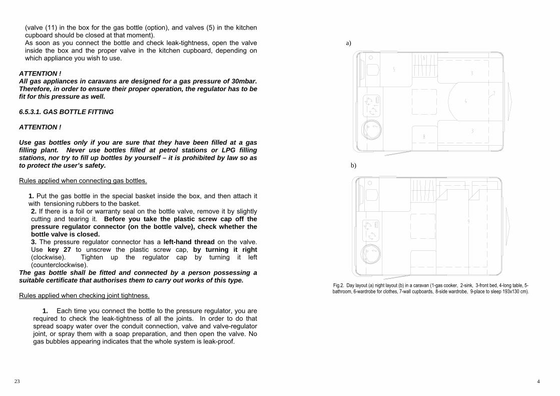
a)
b)
Fig.2. Day layout (a) night layout (b) in a caravan (1-gas cooker, 2-sink, 3-front bed, 4-long table, 5-bathroom, 6-wardrobe for clothes, 7-wall cupboards, 8-side wardrobe, 9-place to sleep 193x130 cm).
4 23

3.3. ACCESSORY EQUIPMENT Trailer Production Plant “Niewiadów” Sp. z o.o. [Ltd.] offers the following accessory equipment for its caravans and trailers:
1. shock absorbers 2. awning manufactured by the Plant 3. entrance step 4. hammock manufactured by the Plant (applies to the N126n-type) 5. gas heater for interior heating 6. refrigerating unit (gas/230V/12V) 7. gas-operated boiler (10l) or electric boiler (5l) for 230V 8. mobile toilet (applies to the N126nt-type) 9. shower (applies to the N126nt-type) 10. roller blinds-shutters (for front and rear window) 11. bicycle rack 12. refrigerating unit - instructions for use 13. heater for interior heating - instructions for use 14. gas boiler - instructions for use 15. mobile toilet - instructions for use
4. CARAVAN OPERATION 4.1. HOOKING UP
1. Hook the caravan to your car’s tow hook using its ball-type coupling. The correct method for connecting the ball and car tow hook is described in section 5.2. of this manual.
2. The emergency cable shall be hooked up so as to ensure that it pulls the caravan’s brakes in cases where the ball-type coupling separates while driving. In order to do that make a loop of the rope, put it onto the mandrel under the hook ball and fix the snap hook on the rope, so as to make it impossible for the rope to slide off the mandrel (Fig.3).
Fig. 3
because of fire or suffocation hazards. 2. Never allow unauthorised and unqualified people to modify wiring systems and equipment (230V and 12V).
6.5.3. THE GAS SYSTEM
Fig. 11. Diagram - the gas system
Before you activate any of the devices, connect the gas bottle to the system (1) (not standard equipment), through the gas regulator (3)
5 22
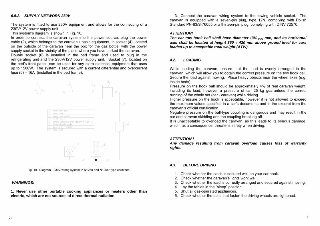
6.5.2. SUPPLY NETWORK 230V The system is fitted to use 230V equipment and allows for the connecting of a 230V/12V power supply unit. This system’s diagram is shown in Fig. 10. In order to connect the caravan system to the power source, plug the power cable (2), which belongs to the caravan’s basic equipment, in socket (4), located on the outside of the caravan near the box for the gas bottle, with the power supply socket in the vicinity of the place where you have parked the caravan. Double socket (6) is installed in the bed frame and used to plug in the refrigerating unit and the 230V/12V power supply unit. Socket (7), located on the bed’s front panel, can be used for any extra electrical equipment that uses up to 1500W. The system is secured with a current differential and overcurrent fuse (5) – 16A (installed in the bed frame).
Fig. 10. Diagram - 230V wiring system in N126n and N126nt-type caravans.
WARNINGS: 1. Never use other portable cooking appliances or heaters other than electric, which are not sources of direct thermal radiation.
3. Connect the caravan wiring system to the towing vehicle socket. The caravan is equipped with a seven-pin plug, type 12N, complying with Polish Standard PN-83/S-76055 or a thirteen-pin plug, complying with DINV 72570. ATTENTION! The car tow hook ball shall have diameter ∅50-0,39 mm, and its horizontal axis shall be located at height 350 ÷ 420 mm above ground level for cars loaded up to acceptable total weight (ATW). 4.2. LOADING
While loading the caravan, ensure that the load is evenly arranged in the caravan, which will allow you to obtain the correct pressure on the tow hook ball. Secure the load against moving. Place heavy objects near the wheel axes (e.g. inside beds). Pressure on the hook ball should be approximately 4% of real caravan weight, including its load, however a pressure of ca. 25 kg guarantees the correct running of the whole set (car - caravan) while driving. Higher pressure on the hook is acceptable, however it is not allowed to exceed the maximum values specified in a car’s documents and in the excerpt from the caravan’s official certification. Negative pressure on the ball-type coupling is dangerous and may result in the car and caravan skidding and the coupling breaking off. It is unacceptable to overload the caravan, as this leads to its serious damage, which, as a consequence, threatens safety when driving.
ATTENTION ! Any damage resulting from caravan overload causes loss of warranty rights. 4.3. BEFORE DRIVING
1. Check whether the catch is secured well on your car hook. 2. Check whether the caravan’s lights work well. 3. Check whether the load is correctly arranged and secured against moving. 4. Lay the tables in the “sleep” position. 5. Shut all gas-operated appliances. 6. Check whether the bolts that fasten the driving wheels are tightened.
6 21

7. Remove the jockey wheel or lift it up as much as possible, by turning the wheel towards the caravan and locking it in position.
8. Lift up the folding supports as much as possible. 9. Check whether all doors, windows and the roof vent are properly locked.
ATTENTION ! While the vehicles are in motion, the roof vent shall be tightly closed (it must be lowered all the way down using the knob).
Moreover, it is required to observe the following advices and guidelines: - it is recommended to transport clothes and bed covering in protective covers, in order to avoid their damage by rubbing against furniture edges, - empty water tanks each time before driving in order to avoid unnecessary caravan loading, - while camping on sloped areas, block both wheels with wedges and pull the parking brake, - in cases where the caravan is parked on soft ground, put pads of a minimum size of 200x200 mm under the folding supports.
4.4. DRIVING
While driving remember that:
– the braking distance for the car - caravan set is greater than for the car alone;
– it is required to maintain a reserved speed and a greater distance from other vehicles, to be able to accelerate in case skidding occurs;
– be careful when driving downhill, especially if the road is wet. 4.5. UNHOOKING
1. Unplug the wiring system, and put the plug in a holder. 2. Disconnect the emergency cable. 3. Unhook the caravan from car tow hook.
Use the jockey wheel to lift the tow bar and separate the coupling. Due to the load weight, be careful when lifting the tow bar. As soon as you unhook the caravan, put a cover over the ball to protect you from getting soiled by the grease remaining on it.
Fig. 9. Diagram - the N126nt-type caravan internal 12V wiring system, with 13-pin plug. ATTENTION ! When using the power supply unit it is recommended to disconnect the 12V wiring system cables from the car.
7 20
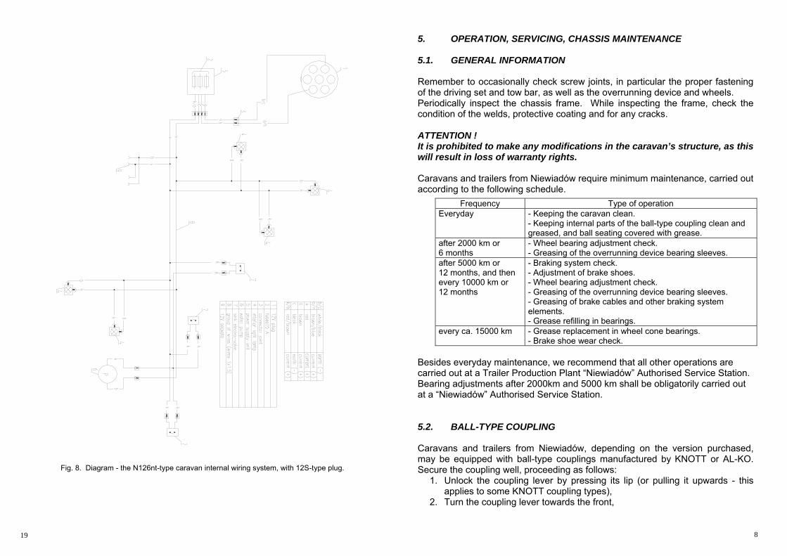
Fig. 8. Diagram - the N126nt-type caravan internal wiring system, with 12S-type plug.
5. OPERATION, SERVICING, CHASSIS MAINTENANCE 5.1. GENERAL INFORMATION Remember to occasionally check screw joints, in particular the proper fastening of the driving set and tow bar, as well as the overrunning device and wheels. Periodically inspect the chassis frame. While inspecting the frame, check the condition of the welds, protective coating and for any cracks.
ATTENTION ! It is prohibited to make any modifications in the caravan’s structure, as this will result in loss of warranty rights. Caravans and trailers from Niewiadów require minimum maintenance, carried out according to the following schedule.
Besides everyday maintenance, we recommend that all other operations are carried out at a Trailer Production Plant “Niewiadów” Authorised Service Station. Bearing adjustments after 2000km and 5000 km shall be obligatorily carried out at a “Niewiadów” Authorised Service Station. 5.2. BALL-TYPE COUPLING Caravans and trailers from Niewiadów, depending on the version purchased, may be equipped with ball-type couplings manufactured by KNOTT or AL-KO. Secure the coupling well, proceeding as follows:
1. Unlock the coupling lever by pressing its lip (or pulling it upwards - this applies to some KNOTT coupling types),
2. Turn the coupling lever towards the front,
Frequency Type of operation Everyday - Keeping the caravan clean.
- Keeping internal parts of the ball-type coupling clean and greased, and ball seating covered with grease.
after 2000 km or 6 months
- Wheel bearing adjustment check. - Greasing of the overrunning device bearing sleeves.
after 5000 km or 12 months, and then every 10000 km or 12 months
- Braking system check. - Adjustment of brake shoes. - Wheel bearing adjustment check. - Greasing of the overrunning device bearing sleeves. - Greasing of brake cables and other braking system elements. - Grease refilling in bearings.
every ca. 15000 km - Grease replacement in wheel cone bearings. - Brake shoe wear check.
8 19
3. Put the catch onto the hook ball and lightly press, it will automatically lock and secure.
KNOTT and selected ALKO couplings are equipped with coupling position indicators. As soon as the coupling is fastened, the indicator will show a green field (KNOTT), or a green field will show above the globular part of the coupling body (AL-KO). After fastening there should be no visible play in the coupling between the catch and the hook ball. If there is any play, it indicates wear of the hook ball or catch, and in this case you should not attempt to drive. If in standard equipment of a caravan with a KNOTT or AL-KO ball-type coupling there is no lock securing the coupling from being disconnected by unauthorised persons, it is possible to get this lock as an extra accessory. 5.3. SUSPENSION AND WHEEL BEARINGS All caravans and trailers from Trailer Production Plant Niewiadów Sp. z o.o. [Ltd.] are provided with axles with rubber springing elements. The suspension system does not require any maintenance, but it should be checked at least once per year at an Authorised Service Station. In cases where defects are found, appropriate repairs or replacements should be carried out either at an Authorised Service Station or at the Trailer Production Plant Niewiadów Sp. z o.o.
Wheel bearings Caravans are fitted with cone bearings. Check the play in bearings after approximately 2000 km, proceeding as follows:
– lift the caravan, ensuring that the wheel is not touching the ground, – check if the wheel rotates smoothly, without noise and side play.
In case of any doubts, or if noisy bearing work is confirmed or visible play occurs in the bearing system, contact an Authorised Service Station to have it adjusted or possibly repaired. Replace grease in bearings approximately every 15000 km. 5.4. DRIVING WHEELS N126n and N126nt-type caravans have wheels with tyres sized 165 R13. The condition for good and safe driving is to ensure the same pressure in all caravan wheels. The optimum pressure range for tyres of caravans loaded up to acceptable total weight is 0.18 ±0.1 MPa.
If you wish to ensure long tyre service life, do the following: – keep required pressure in wheels,
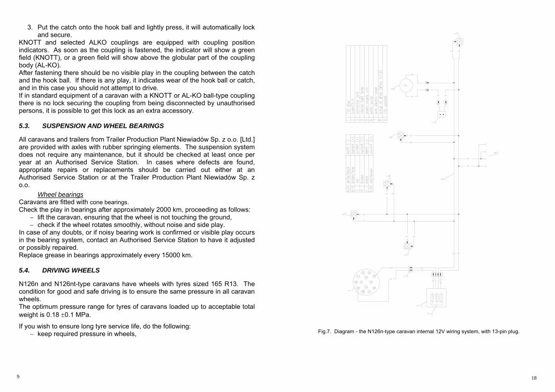
Fig.7. Diagram - the N126n-type caravan internal 12V wiring system, with 13-pin plug.
9 18
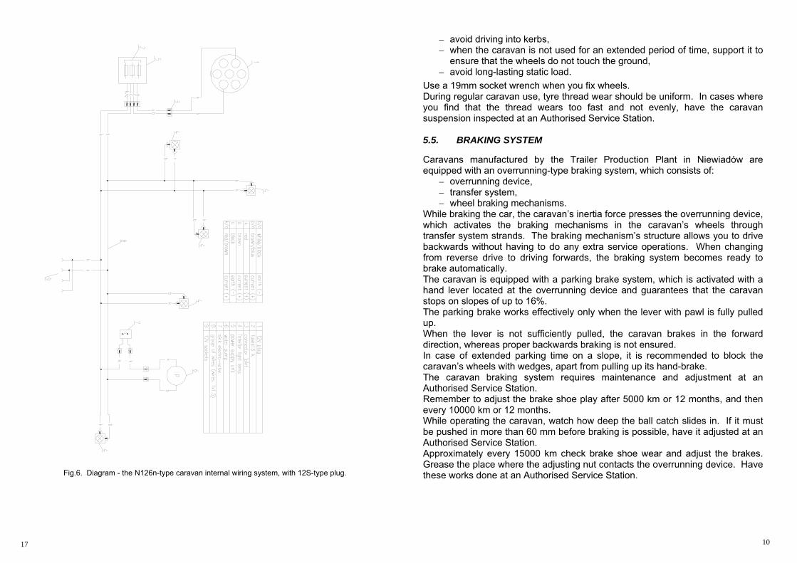
Fig.6. Diagram - the N126n-type caravan internal wiring system, with 12S-type plug.
– avoid driving into kerbs, – when the caravan is not used for an extended period of time, support it to
ensure that the wheels do not touch the ground, – avoid long-lasting static load.
Use a 19mm socket wrench when you fix wheels. During regular caravan use, tyre thread wear should be uniform. In cases where you find that the thread wears too fast and not evenly, have the caravan suspension inspected at an Authorised Service Station.
5.5. BRAKING SYSTEM Caravans manufactured by the Trailer Production Plant in Niewiadów are equipped with an overrunning-type braking system, which consists of:
– overrunning device, – transfer system, – wheel braking mechanisms.
While braking the car, the caravan’s inertia force presses the overrunning device, which activates the braking mechanisms in the caravan’s wheels through transfer system strands. The braking mechanism’s structure allows you to drive backwards without having to do any extra service operations. When changing from reverse drive to driving forwards, the braking system becomes ready to brake automatically. The caravan is equipped with a parking brake system, which is activated with a hand lever located at the overrunning device and guarantees that the caravan stops on slopes of up to 16%. The parking brake works effectively only when the lever with pawl is fully pulled up. When the lever is not sufficiently pulled, the caravan brakes in the forward direction, whereas proper backwards braking is not ensured. In case of extended parking time on a slope, it is recommended to block the caravan’s wheels with wedges, apart from pulling up its hand-brake. The caravan braking system requires maintenance and adjustment at an Authorised Service Station. Remember to adjust the brake shoe play after 5000 km or 12 months, and then every 10000 km or 12 months. While operating the caravan, watch how deep the ball catch slides in. If it must be pushed in more than 60 mm before braking is possible, have it adjusted at an Authorised Service Station. Approximately every 15000 km check brake shoe wear and adjust the brakes. Grease the place where the adjusting nut contacts the overrunning device. Have these works done at an Authorised Service Station.
10 17
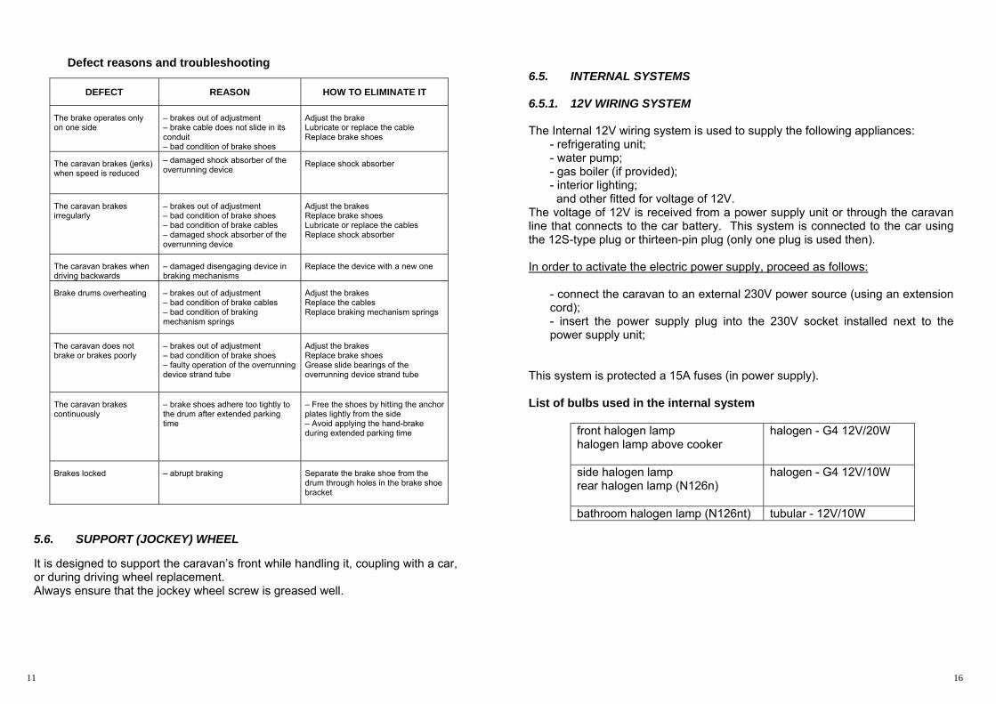
Defect reasons and troubleshooting
5.6. SUPPORT (JOCKEY) WHEEL It is designed to support the caravan’s front while handling it, coupling with a car, or during driving wheel replacement. Always ensure that the jockey wheel screw is greased well.
6.5. INTERNAL SYSTEMS 6.5.1. 12V WIRING SYSTEM The Internal 12V wiring system is used to supply the following appliances:
- refrigerating unit; - water pump; - gas boiler (if provided); - interior lighting; and other fitted for voltage of 12V.
The voltage of 12V is received from a power supply unit or through the caravan line that connects to the car battery. This system is connected to the car using the 12S-type plug or thirteen-pin plug (only one plug is used then). In order to activate the electric power supply, proceed as follows:
- connect the caravan to an external 230V power source (using an extension cord); - insert the power supply plug into the 230V socket installed next to the power supply unit;
This system is protected a 15A fuses (in power supply).
List of bulbs used in the internal system
front halogen lamp halogen lamp above cooker
halogen - G4 12V/20W
side halogen lamp rear halogen lamp (N126n)
halogen - G4 12V/10W
bathroom halogen lamp (N126nt) tubular - 12V/10W
DEFECT REASON HOW TO ELIMINATE IT
The brake operates only on one side
– brakes out of adjustment – brake cable does not slide in its conduit – bad condition of brake shoes
Adjust the brake Lubricate or replace the cable Replace brake shoes
The caravan brakes (jerks) when speed is reduced
– damaged shock absorber of the overrunning device
Replace shock absorber
The caravan brakes irregularly
– brakes out of adjustment – bad condition of brake shoes – bad condition of brake cables – damaged shock absorber of the overrunning device
Adjust the brakes Replace brake shoes Lubricate or replace the cables Replace shock absorber
The caravan brakes when driving backwards
– damaged disengaging device in braking mechanisms
Replace the device with a new one
Brake drums overheating – brakes out of adjustment – bad condition of brake cables – bad condition of braking mechanism springs
Adjust the brakes Replace the cables Replace braking mechanism springs
The caravan does not brake or brakes poorly
– brakes out of adjustment – bad condition of brake shoes – faulty operation of the overrunning device strand tube
Adjust the brakes Replace brake shoes Grease slide bearings of the overrunning device strand tube
The caravan brakes continuously
– brake shoes adhere too tightly to the drum after extended parking time
– Free the shoes by hitting the anchor plates lightly from the side – Avoid applying the hand-brake during extended parking time
Brakes locked – abrupt braking Separate the brake shoe from the drum through holes in the brake shoe bracket
11 16
6.2. REFRIGERATING UNIT The refrigerating unit used by the Trailer Production Plant has three power sources:
- 230V - 12V - propane-butane gas.
Detailed servicing and operating specifications and technical data regarding the refrigerating unit are provided in extra instructions for use (accessory equipment). 6.3. INTERIOR HEATING It is possible to equip the N126n and N126nt-type caravans with propane-butane gas heaters (accessory equipment) for interior heating. The gas operating pressure is 30mbar. In order to activate heating, proceed as follows: - connect the gas bottle to the proper regulator; - open the proper valve located in the kitchen cupboard; - turn the heater knob (gas ignition in the heater is automatic). When you are not using the heating, ensure that proper (marked) valve in the kitchen cupboard is shut. Detailed servicing and operating specifications and technical data regarding heating are provided in extra instructions for use for the heater (accessory equipment).
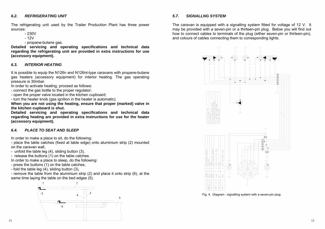
6.4. PLACE TO SEAT AND SLEEP In order to make a place to sit, do the following: - place the table catches (fixed at table edge) onto aluminium strip (2) mounted on the caravan wall, - unfold the table leg (4), sliding button (3), - release the buttons (1) on the table catches. In order to make a place to sleep, do the following: - press the buttons (1) on the table catches, - fold the table leg (4), sliding button (3), - remove the table from the aluminium strip (2) and place it onto strip (6), at the same time laying the table on the bed edges (5).
5.7. SIGNALLNG SYSTEM The caravan is equipped with a signalling system fitted for voltage of 12 V. It may be provided with a seven-pin or a thirteen-pin plug. Below you will find out how to connect cables to terminals of the plug (either seven-pin or thirteen-pin), and colours of cables connecting them to corresponding lights.
Fig. 4. Diagram - signalling system with a seven-pin plug.
12 15
1
2 3
54
6
7
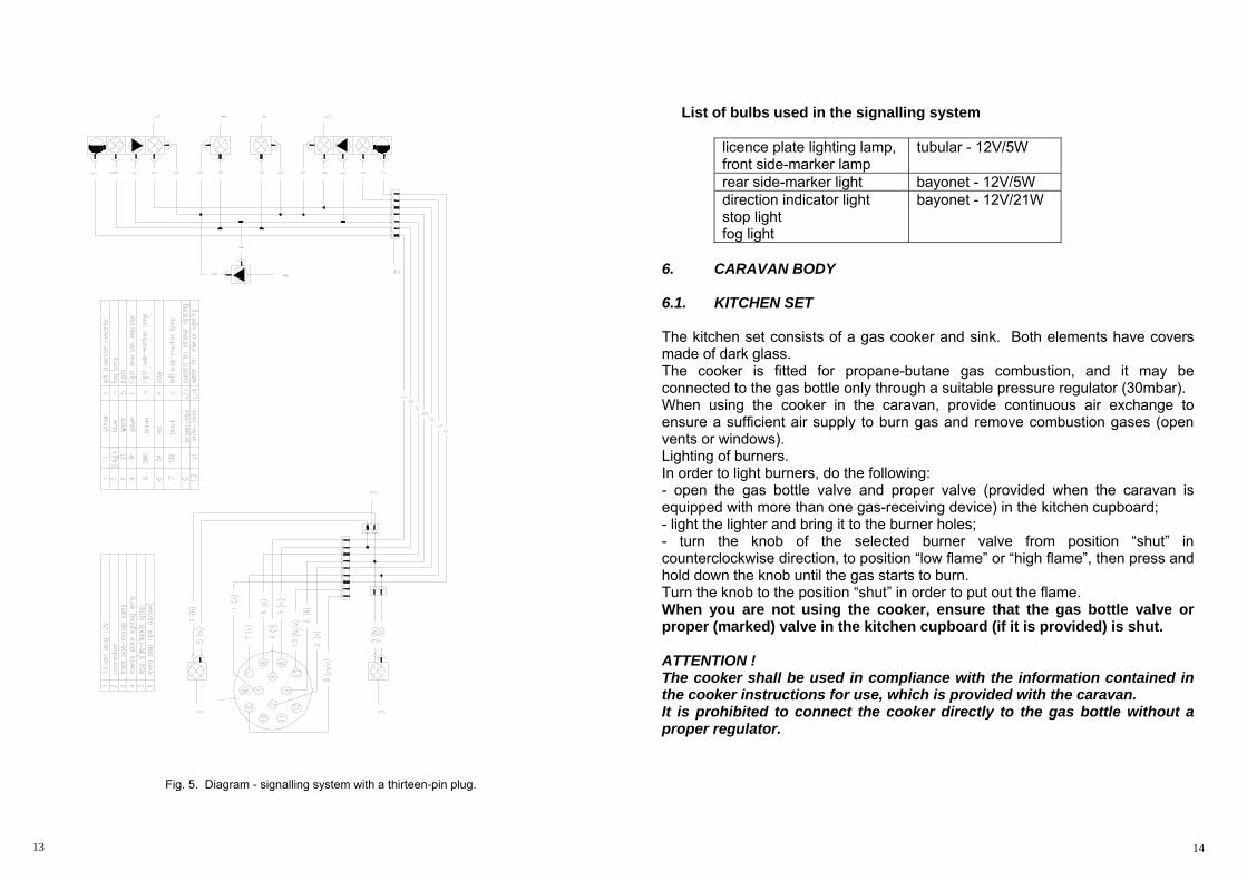
Fig. 5. Diagram - signalling system with a thirteen-pin plug.
List of bulbs used in the signalling system
licence plate lighting lamp, front side-marker lamp
tubular - 12V/5W
rear side-marker light bayonet - 12V/5W direction indicator light stop light fog light
bayonet - 12V/21W
6. CARAVAN BODY 6.1. KITCHEN SET The kitchen set consists of a gas cooker and sink. Both elements have covers made of dark glass. The cooker is fitted for propane-butane gas combustion, and it may be connected to the gas bottle only through a suitable pressure regulator (30mbar). When using the cooker in the caravan, provide continuous air exchange to ensure a sufficient air supply to burn gas and remove combustion gases (open vents or windows). Lighting of burners. In order to light burners, do the following: - open the gas bottle valve and proper valve (provided when the caravan is equipped with more than one gas-receiving device) in the kitchen cupboard; - light the lighter and bring it to the burner holes; - turn the knob of the selected burner valve from position “shut” in counterclockwise direction, to position “low flame” or “high flame”, then press and hold down the knob until the gas starts to burn. Turn the knob to the position “shut” in order to put out the flame. When you are not using the cooker, ensure that the gas bottle valve or proper (marked) valve in the kitchen cupboard (if it is provided) is shut. ATTENTION ! The cooker shall be used in compliance with the information contained in the cooker instructions for use, which is provided with the caravan. It is prohibited to connect the cooker directly to the gas bottle without a proper regulator.
13 14