Embed Size (px)
Citation preview

GO WITH
THE NATION’S
FAVOURITE
Caravan Owners ManualOctober 2020

Welcome to
The Nation’s
Favourite

Welcome to Bailey,The Nation’s FavouriteWe’ve been proudly hitting the road for over 70 years. Along the way we’ve built hundreds of thousands of Bailey caravans and motorhomes, each of them with one thing in mind; creating the perfect holiday.
So, no matter which of our models you have chosen for your home away from home, comfort, convenience and adventure are built into every one.
This manual contains everything you need to know on how to operate your caravan and is also available in a digital format at baileyofbristol.co.uk.
We can’t wait to see you out there.

2
THE NEW AL-KO RANGEREASY AND PRECISE MANOEUVRING AT THE TOUCH OF A BUTTON FOR SINGLE AXLE CARAVANS. AL-KO RANGER, QUALITY AND SAFETY AT AN AFFORDABLE PRICE.
Ask for AL-KO Ranger at your local dealer or mover fitment company. For more information: [email protected] | 01926 818500 | www.al-ko.co.uk
The new manoeuvring system from AL-KO provides effortless control and simple operation to assist you in moving your caravan to exactly where you want it. On shale, tarmac or grass, Ranger takes the struggle away, leaving you to enjoy your holiday.
360°on-the-spot
manoeuvring
| AL-KO Quality For Life Design| Suitable for almost any single axle caravan up to 1800kg| 360 degree on the spot manoeuvring| Manual Motor Engagement| Maximum Climbing Power - up to 18% incline
| Soft Start and Soft Stop| Under Chassis Fitment| Remote Control| Protected Mechanics| 5 Year Warranty*
*According to AL-KO Warranty Terms
There’s no better value in touring
Discover our many sites on historic estates like
Longleat
The Caravan and Motorhome Club
Save each night on pitch fees
Fantastic ferry faresFree glossy monthly magazine
FREE technical help & adviceEnjoy access to over 200 UK sites and 2,500 certificated locations
50% o� selected sites mid-week and more
What are you waiting for? Join today www.caravanclub.co.uk or call 01342 318 813
Discover an unrivalled choice of sites and thousands of exclusive destinations, huge savings on everything from new cars and great days out to restaurant meals and show tickets plus a whole host of exclusive services and tailored insurance products.
Exclusive member o�ers including M6 toll savings
Club Together our online community chat, interact, ask, review
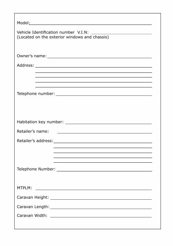
Model:
Vehicle Identifi cation number V.I.N:(Located on the exterior windows and chassis)
Owner’s name:
Address:
Telephone number:
Habitation key number:
Retailer’s name:
Retailer’s address:
Telephone Number:
MTPLM:
Caravan Height:
Caravan Length:
Caravan Width:
Books for enthusiastsby enthusiastswww.haynes.co.uk
Available from all good bookshops or ORDER DIRECT on Tel: 01963 442030
The Motorcaravan Manual (3rd Edition)
ISBN: 978 0 85733 124 3 £22.99
Build Your Own Motorcaravan (2rd Edition)
ISBN: 978 0 85733 281 3 £22.99
The Caravan ManualISBN: 978 1 84425 678 5£22.99
Driving AbroadISBN: 978 1 84425 576 4£12.99
Motorcaravanning Handbook (2nd Edition)
ISBN: 978 0 8 5733 264 6 £14.99
Prices correct at the time of printing
Follow us on:

5
Books for enthusiastsby enthusiastswww.haynes.co.uk
Available from all good bookshops or ORDER DIRECT on Tel: 01963 442030
The Motorcaravan Manual (3rd Edition)
ISBN: 978 0 85733 124 3 £22.99
Build Your Own Motorcaravan (2rd Edition)
ISBN: 978 0 85733 281 3 £22.99
The Caravan ManualISBN: 978 1 84425 678 5£22.99
Driving AbroadISBN: 978 1 84425 576 4£12.99
Motorcaravanning Handbook (2nd Edition)
ISBN: 978 0 8 5733 264 6 £14.99
Prices correct at the time of printing
Follow us on:
6CONTENTS
INTRODUCTION Introduction 11Driving Licences 12
STATEMENT OF CONFORMITY Statement of Conformity 12
WARRANTY Touring Caravan Warranty Cover 136 Year Bodyshell Integrity Warranty 13Warranty Extension 133 Year Manufacturer’s Warranty 13Warranty Extension 14Customer Support 14Terms and Conditions 14Cover 14Term 14Repairs 14Registration and Use 15Exclusions and Liability 15Warranty Registration 16
CENTRAL REGISTRATION AND IDENTIFICATION SCHEME (CRIS) CRiS Registrations: 17
COUNTRY AND COASTAL CODE Code of Conduct 18Arrivals 18Vehicle Movement 18Use of Site 18Cautions 18Noise 18Dogs and Pets 18Fire Precautions 18Awnings and Tents 18Departure 18Handbook 19Environment 19The Country Code 19The Coastal Code 19Roof Loading 19Safety and Security 19Children 19Fire Extinguishers 20In Case of Fire 20Ventilation and Condensation 20Petrol and Diesel Fumes 20Original Equipment Appliances 20Portable Appliances 20Modifications 20
CARAVAN AND TOW VEHICLE Caravan and Towing Vehicle Terms 21Kerb Weight of Towing Vehicle 21Caravan to Towing Vehicle Weight Ratio 22Towing Vehicle’s Rear Suspension 22Recommended Towball Height 22Secondary Braking Cable 22Loading and Distribution of Weight 23Hitching Up 24Hitching the Caravan to the Tow Vehicle 24
TOWING Speed Limits 26Pulling Away 26Caravan Handling 26Reversing 26Motorway Driving 26Mirrors 26Snaking 26Stabilisers 27Road Lighting 2713 Pin Plug 27
UNHITCHING Levelling the Caravan 29
WHEELS AND TYRES Tyres 30Wear and Damage 30Wheel, Tyre and Bolt Safety Fitment 30Tyre Pressures 30Wheels 31Spare wheel 31
SPARE WHEEL CARRIER To lower the Spare Wheel 31Returning the Spare Wheel 32TPMS Tyre Pressure Monitoring 32
THE AL-KO CARAVAN CHASSIS (AKS 3004) Operating Instructions 36Coupling 36Stabiliser Unit 37Uncoupling 37Manoeuvring Operation 38Noises While Driving 38Remedial Action 38Storing 38Towing Ball 38Overrunning Device 39Jockey Wheel 39Brake Linkage 39Corner Steadies 39C
ON
TEN
TS
7Braking System Adjustment 39Chassis Lubrication Points 41AL-KO ATC Trailer Control System 41Operating Instructions 41Spare Parts 41Independent Suspension 42Coupling Head 42
TRACKER MONITOR Operating Instructions 43General Questions 43
WATER SYSTEMS : WITHOUT AN ON-BOARD WATER TANKWater Supply 45Drain Valve 45Setup 45Removing the Plug 46
WATER SYSTEM S: WITH AN ON-BOARD WATER TANK Water Supply 47Filling the On-board Tank 47Internal Supply 47Tank Drain Operation 48Draining and Winterization 48Procedure 48Initial Setup 48Sterilising 48Water System Troubleshooting 49Adjusting your Pressure Switch 50
THE GAS SYSTEM General information 54Types of gas 54The Regulator 54Changing Gas Cylinder 55Gas Safety Advice 55Gas Leaks 55Ventilation 56Gas BBQ Point 56
THE ELECTRICAL SYSTEM-230V Instructions for Electricity Supply 57Upon Arrival at Caravan Site 57Upon Leaving Caravan Site 57Overseas Connections 57Mains Unit 57
THE ELECTRICAL SYSTEM- 12V Battery Box Connections 59
CONTROL PANELSCBE Control Panels 61
STATUS 570 ANTENNA Travelling 63Operating 63DAB and FM Radio Operation 63Gain Control 63LED Light 63Short Hook Up: Test 1 63Short Hook Up: Test 2 64Antenna Dome Coaxial Cable 64
SOLAR DUAL BATTERY CHARGER SDC 10/20 Operating Instructions 65Function 65Charging Process 65Bulk Phase 66Absorption Phase 66Float Phase 66Parallel Mode 66Settings 66Battery Type 66Charging Current Distribution 66PWM Charging Frequency 67Query 67Function Display / Troubleshooting 67Repairs 67
HEATING SYSTEMS (ALDE) Operating Instructions 68Description of Functions 68Gas Heating 68Electric Heating 68Domestic Hot Water 68Draining Freshwater 69Heat Transfer Fluid 70Filling 70Central Heating 71Circulation Pump 71Bleeding Air 71Air Lock 72230v Electric 72LPG 72Flue 73Maintenance 73Winter 74Troubleshooting 74Warranty 75
CO
NTE
NTS
8ALDE CONTROL PANEL Starting the System 76Standby Screen 76Main Menu 77Desired Room Temperature 77Domestic Hot Water 78Electric Heating 79Gas Heating 79Shutting Down the System 80Setup 80Restore Default Factory Settings 80Setup Expansion Tank Pump 80Set up Antimicrobial Function 80Setup Standby Screen for Bedtime 80Maintenance 80Troubleshooting 80Battery Backup 81
TRUMA COMBI COMBI E Series 82Function Description 82Heating and Hot Water Mode 82Hot Water Mode (Filled Boiler) 83Operating Instructions 83Room Thermostat 83Filling the Water Heater 83Draining the Water Heater 83Filling the Water Heater (Frost Control) 84Draining Water Heater (Frost Control) 84Start Up 84Switching Off 84Maintenance 84Fuse 12v 85Fuse 230v 85
TRUMA DIGITAL CONTROL PANELSafety Instructions 86Display and Control Elements 86Rotary Push Button 86Start/Standby Screen 87Functions 87Change the Room Temperature 87Select Energy Source 88Select Fan Level 88Set the Room Temperature 88Set the Warm Water Level 88Select Energy Source 88Select Fan Level 88Set the Timer Switch 88Activate the Timer (ON) 89Deactivate the Timer (OFF) 89Set Time 90Display Mains Voltage 230v 90Warnings 90
EXTERIOR FEATURES GRP 91
ROOFLIGHTS HEKI Rooflights 91 Safety instructions 92Care instructions 92MPK Rooflight 92
COOKING EQUIPMENT Operation 93Using the Hotplate Gas Burners 93Using the Electric Hotplate 94Using the Grill 94Using the Oven 95Oven Temperature Control 95Cooking Guidelines 95Do’s and Don’ts 96Maintenance and Servicing 96Service 96
CARBON MONOXIDE ALARM Features 98Testing 98Testing the Sensor 98Maintaining/Testing Your Detector 99
SMOKE ALARM Features 100Simple Maintenance 100
BATHROOM CARE Bathroom Shower Tap 101Mirrors 101Ecocamel Shower Head 101
THETFORD C262 TOILET Parts 102Using The Toilet (Standard) 102Cleaning and Maintenance 102Toilet Bowl 102Waste Holding Tank 103Winter Operation 103Preparing the Waste Holding Tank 104Emptying the Waste Holding Tank 104
REFRIGERATORS Cleaning 105Maintenance 105Safety Instructions 106User’s Responsibility 106Information on Coolant 106Appliances with Electronics (MES/AES) 106Operating the Refrigerator with Gas 106C
ON
TEN
TS
9Electrical Operation 108Mains power 230v 108Gas Operation 108
RML9330/RM8550/RMS8550/RM8500 Operation 108Lighting 109Parking Lock 109Exchanging the Igniter’s Battery 110
Troubleshooting 111
RMD8551Operation 111Troubleshooting 111
STAINLESS STEEL SINK Care 113
SOFT FURNISHINGS Carpet 116Upholstery 116Cleaning and Care 116Winterisation and Storage 116Curtains 116
REMIS BLINDS Remibase 116Cleaning 117Remi Flair 117Function 117Maintenance 117
GENERAL CARE AND MAINTENANCE OF YOUR CARAVAN Exterior 118Cleaning/Usage Information 118
GENERAL CARE Acrylic Windows 118Window Catches and Stays 119Humidity 119About Condensation 119How to Keep Your Caravan Dry 119Furniture 119
WINTERISATION & STORAGE Procedure 120
MODIFICATIONS & DIY WORK Warning 120
CARAVAN KEYS Information 120
SPARES & AFTERSALES Accessories 120 BED MAKE UP Front Bed Make Up 121Rear Dinette Bed Make Up 122Grande Dinette Make up 123 Retractable Rear Bed 124Additional Fold Out Rear Bed 124Free Standing Table 125
THE SERVICE MANUAL
CO
NTE
NTS
©BAILEY OF BRISTOL 2020. ALL RIGHTS RESERVED
No part of this document may be reproduced or transmitted in any form or by any means, electronic or mechanical, for any purpose, without the express permission of Bailey of Bristol Ltd.

JVC's new Digital radio equipped KD-DB98BT, has all your music and radio needs covered. You can also use your Smartphone as a remote control with our free remote app for compatible Apple and Android devices. Change from CD to radio or iPod, select a different radio station, and adjust the volume or tone directly from your smartphone's screen!
Also with your clean driving licence in mind, Bluetooth hands-free phone control with voice activation is included.*
Ask your Baileys dealer for more details.
The “Smart” entertainment solution for your adventures!
http://uk.jvc.com
*With compatible voice control equipped smartphoneJVC CS-V416 speakers sold separately
11
JVC's new Digital radio equipped KD-DB98BT, has all your music and radio needs covered. You can also use your Smartphone as a remote control with our free remote app for compatible Apple and Android devices. Change from CD to radio or iPod, select a different radio station, and adjust the volume or tone directly from your smartphone's screen!
Also with your clean driving licence in mind, Bluetooth hands-free phone control with voice activation is included.*
Ask your Baileys dealer for more details.
The “Smart” entertainment solution for your adventures!
http://uk.jvc.com
*With compatible voice control equipped smartphoneJVC CS-V416 speakers sold separately
INTR
OD
UC
TIO
N
INTRODUCTION
Congratulations on the purchase of your Bailey caravan. We would like to welcome you to the prestigious rank of Bailey owner. We are confident your caravan will give you many years of enjoyment.
This handbook has been designed to assist you in obtaining the maximum benefits and pleasure from your caravan. The information and hints will be beneficial and help you protect your investment, whether you are a new or experienced caravan owner.
Information leaflets and literature on safe operation of appliances and equipment fitted to your caravan are included in the Bailey information pack. Please read these carefully prior to the use of these appliances.
This manual covers the essential parts of your caravan, however it is not exhaustive. Detailed information can be obtained from individual manufacturers regarding their products.
Failure to observe recommendations or precautions within this or any other related documentation may lead to incorrect operation of equipment. This may cause subsequent risk to occupants.
Regular maintenance is necessary to ensure trouble-free usage of your caravan. Your Bailey retailer is equipped to offer service facilities, repair work and any spare parts that you may require.
Always consult your supplying retailer before any additional equipment is fitted. This is to ensure the location of appropriate structural support.
Retailers are not agents of Bailey and have absolutely no authority to bind Bailey by any express or implied undertaking or representation.
Please be aware that certain sections are only applicable to certain models.
In order to enable Bailey and its retail partners to deal with your queries efficiently, always quote your caravan’s vehicle identification number (VIN) which can be found on the offside chassis member. It is also featured on all major windows.
It is policy within Bailey to continuously improve their vehicles. While all illustration and descriptive material within this handbook is correct at the time of going to print, the ever changing market and supply situations may prevent us from maintaining the exact specification details of this handbook. Bailey therefore reserve the right to alter the specification of its products at any time without prior notice.
Bailey offer a variety of leisure vehicles. While each vehicle is designed to feature optimum storage, seating, sleeping and fluid capacities, it is the customer’s responsibility to select the correct loads without exceeding the weight capabilities of your chosen towing vehicle. These weights can be found on the weight plate located outside your vehicle next to the exterior door and also on the plate found within the gas locker.
SAFETY
This handbook contains the information that you will require for your safe enjoyment of your caravan. All the information contained within is important. However, to draw your attention to specific items we have prefixed them with the following symbols to indicate a warning, caution or note respectively.
WARNINGS are instructions that if ignored can cause the user(s) physical harm.
CAUTIONS are instructions that if ignored can result in damage to the caravan.
NOTES are reminders that should be heeded.
IMPORTANT SAFETY NOTES
STATEMENT OF CONFORMITY
All Bailey caravans have been certified by the National Caravan Council for compliance with UK and European standards and legislation
along with industry codes of practice relating to health and safety issues. The approval process covers the testing and inspection of critical areas of the product including fire safety, weights and dimensions, gas, electrics and ventilation. Every Bailey caravan carries the NCC Approved Caravan badge. The NCC conducts unannounced inspections at their members’ factories to ensure continued compliance.
NCC approval gives you peace of mind that your caravan is safe and legal.
Your Bailey caravan is also European Whole Vehicle Type approved. This certification assures you that your caravan meets all European regulations and has been constructed to conform to the rigorous standards for both manufacturing and product safety. It enables you to register your vehicle in other European countries.
The certificate of conformity can be found in the document pack provided with your vehicle.
If for any reason a replacement certificate should be needed your Bailey Caravan retailer is responsible for accessing one through the NCC system.
Please refer back to your retailer for additional copies. European Representative AR experts is the legal representation established in the European Union who is duly appointed by Bailey Caravans LTD to represent before the approval authority or the market surveillance authority and to act on the Bailey’s behalf in matters covered by Regulation (EU) 2018/858
AR Experts B.V.Amerlandseweg 73621 ZC BreukelenThe Netherlands
12IN
TRO
DU
CTI
ON
To ensure all the occupants of your caravan enjoy a safe and relaxed environment, please observe the following:
• Ensure all the occupants are aware of the vehicle’s escape routes.
• Always keep escape routes and exit points clear from obstruction and debris.
• Provide one dry powder fire extinguisher of an approved type or complying with ISO 7465 and BSI 5423 of at least 1kg (2.2lb) capacity by the main door, and a fire blanket next to the cooker. Familiarise yourself with your fire extinguisher.
Your tourer is a compact living environment, and appliances should be treated in the same way as those in the home.
• Always keep young children away from hot surfaces.
Your tourer is supplied with an EN1645 approved caravan step. Always take care when entering or exiting your tourer ensuring that the step is securely located before use. Do not use a damaged or broken step.
• The torque setting of the caravan’s wheel bolts should be checked 30 miles after collection from the caravan retailer or after a service or wheel change. Thereafter, wheel bolts should be checked before every journey. The torque settings and tightening sequence are detailed in the caravan and tow vehicle section.
• Never attempt to lift the tow hitch with your hands when hitching the caravan to the tow vehicle or at any other time. Always raise or lower the tow hitch by winding the handle on the jockey wheel.
• Always ensure that the green button located on the leading edge of the coupling head is raised before towing. (Coupling specific).
DRIVING LICENCES
Drivers passing their test after 1st January 1997 are restricted to a car/caravan combination not exceeding 3,500kg (maximum laden weight).
13
WA
RR
AN
TY
WARRANTY
If you have a problem or enquiry relating to your caravan please follow these steps:
• Check the handbook concerned
• Contact your supplying retailer for assistance.
The following suppliers provide a direct aftersales service.
It is with the retailer that the purchaser’s Contract of Sale exists and subsequently Bailey cannot enter into any discussions with the purchaser.
All Bailey products are classified as “portable”. All work under warranty requires that the caravan be delivered to and collected from the Bailey retailer. Every effort has been made within this handbook to accurately reflect and describe Bailey caravan models. Our policy of continued improvements and change in market and supply conditions mean that we reserve the right to alter specification without prior notice. Some materials used in the production of our caravans can result in variations to the figures quoted in respect of measurements and weights.
TOURING CARAVAN WARRANTY COVER
ATotal customer satisfaction is top priority at Bailey and the quality ethos extends to the after sales service and market leading manufacturer’s warranty package that comes with every new Bailey touring caravan. In this way we not only ensure long-term peace of mind but also enhance the re-sale value of your investment. 6 YEAR BODY SHELL INTEGRITY WARRANTY Bailey Alu-Tech caravans are covered by a six (6) year Bodyshell Integrity Warranty from the initial date of purchase. This cover extends to any structural degradation to the bodyshell that arises as a result of water ingress through any permanently sealed seam or joint (with the exception of exclusions stated in the terms and conditions.)
WARRANTY EXTENSION An additional four (4) year extension to the standard Bodyshell Integrity Warranty cover (making 10 years cover in total) is available as a cost option through your supplying Retailer 3 YEAR MANUFACTURER’S WARRANTY For a period of twenty-four (24) months from the initial date of purchase Bailey of Bristol offer a comprehensive warranty on all parts and components as well as full coverage for any manufacturing faults forming part of the original specification of the vehicle, with the following specified exceptions: The following items are covered for one (1) year from the date of first registration • Microwave Ovens• JVC Stereo Radio/CD/MP3 Players
& Speakers
The manufacturer’s warranty then extends to an additional twelve (12) months on the following items.• Chassis: all chassis members including
corner steadies• Suspension: axle suspension and braking
system (excluding any damage to or faults in brake drums and shoes that are caused through misuse of the braking system or from normal wear and tear)
• Running Gear: road wheels (excluding tyres)• Towing Mechanism: all mechanical
components fitted to vehicle (excluding electrics)
• Cooker: the cooker unit including burners, grill, oven, flame failure device and igniter
• Refrigerator: door seal condenser, gas control valve, gas igniter, flame failure device, 12v and 230v heater elements, gas thermostat, 230v thermostat and 230v temperature control switch
• Water System: water heater (gas or electric), fresh water tank, water pump, water, gauges, taps and shower head
• Electrical System: mains hook up input connector, ELCB, battery charger and
• distributor unit and interior lighting units (excluding bulbs)
• Cassette Toilet: the cassette toilet is covered (excluding seals, valves and glands)
• Heating System: thermostat, motor, switches, control unit, gas heater, flame failure
14W
AR
RA
NTY
• device and igniter (excluding ducting and fittings)
• Windows: the functionality of the opening and closing system (stays, handles and catches) and a warranty against the cracking of the acrylic
• Upholstery: zips, seams and colour fastness
The following items are also not covered for rental vehicles• Cosmetic damage to interior and exterior
fittings and surfaces
WARRANTY EXTENSION An additional three (3) year extension to the standard Manufacturer’s Warranty cover for mechanical and electrical components of a leisure vehicle both external and internal (making 6 years cover in total) is available as a cost option through your supplying Retailer. Customer Support Approved Bailey Retailers enjoy industry-leading after sales support service from the manufacturer and they will be able to offer all the help you need to rectify any issues that may occur. They should be your first point of contact on any subject relating to your vehicle. It should be noted that Bailey Approved Retailers sell our products of their own choice and not as agents of Bailey. Accordingly, they have no authority to bind Bailey or make representation or undertaking whatsoever on behalf of Bailey. TERMS AND CONDITIONS The Bailey Warranty Cover set out above is offered subject to the following simple terms and conditions: COVER 1. During the term of the Warranty Cover, subject to these terms and conditions, Bailey will, through an Authorised Service Centre, at its option repair or replace all parts and components of the caravan that are included in the Warranty Cover and which suffer a defect in manufacture or workmanship. An Authorised Service Centre means either Bailey itself, a Bailey Approved Retailer or a Bailey Approved Service Centre. Any part which is replaced becomes the property of Bailey. Any replacement parts are covered for the unexpired term of the Warranty Cover.
TERM 1. The initial duration of the Bodyshell Integrity Warranty is six (6) years and the duration of the Manufacturer’s Warranty is three (3) years in both cases starting from the original purchase date of the vehicle. It is a condition of the warranty that an annual service is performed on the vehicle in accordance with the service plan. Failure to comply with this term will invalidate the warranty. 2. The unexpired term of the Warranty Cover on your vehicle may only be assigned, transferred or novated to subsequent owners with Bailey’s consent (not to be unreasonably withheld) and on payment to Bailey of a transfer fee of £35. Transfer can only be made within the first three months (3) of the date subsequent ownership was taken and full documentary evidence that the vehicle has been serviced annually along with evidence of the date of subsequent purchase (in the form of a VAT sales receipt, invoice or bank/credit card statement) must be provided at the time of assignment in accordance with the terms and conditions detailed above REPAIRS 4. The caravan must undergo a full annual service and inspection, including a moisture survey, carried out, subject to paragraph 5 below, by an Authorised Bailey Service Centre or by a service agent that is a member of the National Caravan Council’s Approved Workshop Scheme (AWS). 5. The final annual service in any warranty period must be carried out before the end of that warranty period, but all other annual services may be carried out within six (6) weeks either side of each anniversary of the original purchase date. The original VAT invoices must be retained as proof that these annual inspections have been carried out. 6. Where an annual inspection identifies that repairs to the vehicle are necessary, the caravan must be made available for repair within six (6) weeks of the date of inspection for the purpose of carrying out the repair work. Repairs under warranty must be undertaken by either Bailey itself, a Bailey Approved Retailer or a Bailey Approved Service Centre.
15
WA
RR
AN
TY A
ND
REG
ISTR
ATI
ON
7. No repairs, including the fitting of any replacement unit, may be undertaken or commenced under the terms of the Warranty Cover unless prior written authorisation is obtained from Bailey via a Bailey Approved Retailer or a Bailey Approved Service Centre. No liability will exist with regard to any warranty claims not authorised in this way. 8. Bailey reserve the right to examine the vehicle before any repairs commence or any replacement part is fitted. REGISTRATION & USE 9. The Warranty Registration Form must have been sent to Bailey within six (6) weeks of the original purchase date. It is the responsibility of the Bailey Retailer to forward this information to Bailey. This is part of the terms of trading that that the Bailey Retailer has with Bailey. 10. The caravan shall: • Only be used for its ordinary and intended
purpose and shall not be subjected to any • treatment or conditions which could
reasonably be foreseen to cause or result in damage to the vehicle or excessive wear and tear
• Only be towed by a private car or private 4x4 vehicle
• Whilst registered under private ownership must not be put out to hire, reward or any other commercial use, nor used in any race, competitions or rallies whether timed, official or otherwise.
EXCLUSIONS & LIABILITY 11. Bailey’s liability under this warranty shall be limited to supplying the reasonable costs of labour and materials required for the repair or replacement of faulty parts or components. Bailey shall be entitled to charge for any repair work which is necessitated by virtue of any loss or damage caused by your negligence or default or incurred as a result of any modifications you have made to the vehicle. This warranty does not cover repair costs other than labour and materials. 12. The Warranty Cover does not include: • Repair or replacement of parts,
components, seams or panels which are not part of the original construction of the
caravan, or which have been tampered with or undergone unauthorised modifications, or which have been repaired otherwise than by An Approved Bailey Retailer or a Bailey Approved Service Centre.
• Parts or components other than those specifically listed in the Bodyshell Integrity Warranty and Manufacturer’s Warranty descriptions set out above
• General maintenance or components failing due to fair wear and tear or normal deterioration repairs necessitated by lack of routine or regular maintenance. Particular attention is drawn to the Owner’s Manual and Service Handbook supplied with the caravan and any maintenance instructions or notices published from time to time by Bailey relating to the proper care and maintenance of vehicles
• Structural degradation or other damage caused by water ingress through non-permanently sealed seams or joints (such as, without limitation, around windows, hatches, doors and rooflights), beyond the initial 24 months of the Manufacturer’s Warranty.
13. No liability will be accepted for: • Damage caused by neglect or abuse,
corrosion, intrusion of foreign or deleterious substances, lack of servicing, over-heating, freezing, or the continued use of the vehicle after a fault has become evident
• Any loss or damage caused by parts not covered by this Warranty Cover, including soft furnishings or trim
• Any accidental or fire damage or any losses incurred by accident or fire
• Transport costs to and from point of repair. Bailey will only be liable for costs which are incurred as a direct consequence of the event, defect or fault leading to the claim being made under this warranty. No liability will be accepted for any other loss or damage (such as loss of income or revenue, or loss of business or profits), costs, expenses or other claims for compensation howsoever arising which was not reasonably foreseeable by both parties when the caravan was originally purchased. Bailey will not be liable for any loss or damage suffered by third parties, nor for bodily injury not caused by our negligence.
16W
AR
RA
NTY
AN
D R
EGIS
TRA
TIO
N
Nothing in this warranty shall limit in any way our liability: for death or personal injury caused by our negligence; for fraud or fraudulent misrepresentation; or for any matter for which it would be illegal for us to exclude, or attempt to exclude, our liability. The purchaser has statutory rights in addition to this warranty and this warranty does not affect those statutory rights. This warranty shall be governed by and construed in accordance with the laws of England and the parties irrevocably submit to the nonexclusive jurisdiction of the courts of England. WARRANTY REGISTRATION
The supplying retailer must explain the warranty terms and conditions to you, and complete the warranty registration process online. Your warranty will start on the day that the vehicle is first registered in the UK or 12 months from the date on which the vehicle was invoiced to the supplying retailer, whichever is the earlier. The name and address of the warranty provider is: Bailey Caravans Limited, South Liberty Lane, Bristol, BS3 2SSThis version: May 2020
Customer’s signature:
..................................................................................
Date:
..................................................................................
Retailer’s signature:
..................................................................................
Date:
..................................................................................
17
WA
RR
AN
TY A
ND
REG
ISTR
ATI
ON
CENTRAL REGISTRATION AND IDENTIFICATION SCHEME (CRiS)
CARAVAN REGISTRATION This caravan has been security marked and recorded under the Caravan Registration and Identification Scheme that is recognised by the Caravan Industry and the National Caravan Council.
Shortly after purchasing this caravan you should receive your Touring Caravan Registration Document. It will be sent by post to your home address.
Your Touring Caravan Registration Document will include a 17 character VIN (Vehicle Identification Number), shown in the top right hand corner. This 17 character VIN will also be permanently marked on the caravan chassis.
For security purposes, never leave the Touring Caravan Registration Document in the caravan. It should always be stored in a safe place away from the vehicle.
If you sell the caravan please follow the instructions on the Touring Caravan Registration Document.
If, for any reason, you do not receive a Touring Caravan Registration Document or any of the details recorded are incorrect, please contact:
CRIS REGISTRATIONS:For help, support and advice Contact CRiS:NCC, CRiS Ltd, PO Box 445, Aldershot, GU11 9SF.TEL +44 (0) 203 282 1000
VIN Chip Caravan Identification The caravan’s unique 17 character VIN will be incorporated into VIN Chip tamper evident labels; the master VIN Chip label is situated on the front near side window, others are located in the gas locker and a maximum of 10 placed on the inside of all windows (with the exception of opaque windows).
Three electronic RFID chips containing the individual identity of your caravan are concealed within the caravan and can only be read by using a specially programmed RFID scanner.
18C
OU
NTR
Y A
ND
CO
AST
AL
CO
DE
COUNTRY AND COASTAL CODE
CODE OF CONDUCT – CAMP SITES
Check the site regulations.
ARRIVALS
Report to reception immediately on arrival.
VEHICLE MOVEMENT
Keep to roadways unless otherwise directed.Adhere to speed limits. Remember that the stopping distance on grass is considerably greater than on tarmac.Only a person in possession of a current driving licence may drive onsite.Park as advised on your pitch. Where possible leave 6 metres (20ft) of free space around your vehicle.
USE OF SITE
Use the electrical mains hook-up in the correct manner and with caution.Ensure that all fresh water taps and connections are turned off after use.Have care and consideration for others when using all facilities. Leave them clean and tidy. Ensure young children are accompanied at all times.
CAUTIONS
To avoid possible damage to sewage purification works, only approved chemical fluids must be used. Under no circumstances may coal tar, phenol or caustic-based fluids be used. Disposable nappies and similar bulky items must not be put into the chemical closet emptying points but should be wrapped in a polythene bag and placed in the container provided.
NOISE
All occupants should refrain from making excessive noise.Flying kites and model aircraft and the use of items like catapults or air guns, as well as ball games, should not be permitted among or close to caravans.Musical instruments, music players, radios and televisions should not be used to the inconvenience of other people onsite.Open and close doors quietly.Power generators must be adequately silenced and used with consideration in accordance to
restricted site times.
DOGS AND PETS
All dogs and other pets should be kept under control.Unless permission has been granted, no animal should be let loose on the site and leads should not exceed 3 metres (10 ft).No animal should be allowed in the shower/ toilet block.Do not let animals foul the site.
FIRE PRECAUTIONS
Adhere to and make note of all fire precautions, including the whereabouts of the fire points.
It is recommended that a 1kg (2.2lb) dry powder fire extinguisher is carried within the caravan. It should comply with BS 5423 ISO 7465 and be marked BSI or FOC approved. It is important to check at regular intervals that the extinguisher is working as is required by types meeting BS 5423. Ensure the use-by date is frequently checked.
Careful thought is necessary for the positioning of a fire extinguisher, which should be near to the door but not too close to cooking equipment where flames could make it unreachable. In the kitchen area, a fire blanket is a worthwhile precaution.
Unless permission has been granted, barbecues should not be used. When permission has been given, take care and consider other site users. Ensure that the environment remains pleasant for everyone.
AWNINGS AND TENTS
Awnings and tents should only be used when permission has been granted.When on grass and staying for more than a few days, the ground sheet and/or side flaps of awnings should be periodically raised in order to avoid damage to the ground.
DEPARTURE
Leave the pitch clean and tidy.Upon leaving, check out with reception, paying the required dues.
19
CO
UN
TRY
AN
D C
OA
STA
L C
OD
E
Under no circumstances should:• Litter be disposed of other than in the
receptacles provided.• Water be allowed to escape from the
vehicle.• Chemical toilets be emptied except into the
disposal places agreed with the landowner.• Washing or similar be hung outside of the
vehicle.
HANDBOOK
Before using the caravan, all aspects of the handbooks should be read and adhered to.
ENVIRONMENT
Care and consideration should be taken to protect the environment.
Observe the Country and Coastal Codes shown below.
THE COUNTRY CODE
Enjoy the countryside but respect its life and worth.
More people than ever before are exploring the countryside, interested in farming, plant life, bird watching or just observing the general wildlife. Whatever your interest, there is a lot to learn. Please observe the following code.
• Guard against all risk of fires. Hay and heath land can catch alight easily and once ablaze are very hard to put out.
• Remember fire spreads quickly.• Keep to public paths across farmland.• Use gates and stiles to cross fences,
hedges and walls.• Leave livestock, crops and machinery
alone. View from a distance.• Take your litter home; it is unsightly and
harmful to wildlife.• Help to keep all water clean.• Take special care on country roads.• Make no unnecessary noise. Most animals
are timid, noises can disturb them unnecessarily.
If you want to get the best out of the countryside, travel around as quietly as possible.
THE COASTAL CODE
As our coastlines are increasingly used for recreation and education, the following suggestions are made to enable us to enjoy our inheritance and preserve it for posterity.• Do not trample about, or move rocks
unnecessarily.• Do not frighten seals or sea birds.• Do not spear fish.• Live molluscs and crustaceans should not
be collected as souvenirs, dead shells can usually be found;
• Shellfish can take years to grow and fines can be imposed for not observing national regulations.
• Do not pull up seaweed unnecessarily.• Make your visit instructive, not
destructive.• Look at material, don’t remove it. • Observe bye-laws and be considerate to
others.• National Trust property or Country Parks
have regulations to protect the wildlife. Follow these.
ROOF LOADING
‘Do not climb on theroof of your caravan.
SAFETY AND SECURITY
Your attention is drawn to the notice fixed in your Caravan advising on fire protection, ventilation and what to do in case of fire.
CHILDREN
Never leave children alone in the caravan. Ensure all potentially dangerous items are kept out of reach.
When upper bunks are used by children, especially those under the age of six (6), care should be taken to ensure against the risk of them falling out. These bunks are not suitable for use by infants without supervision.
20C
OU
NTR
Y A
ND
CO
AST
AL
CO
DE
UPPER BUNKS
Please ensure upper bunks are only used for sleeping. When upper bunks are used fall out protection must be always be in place.
FIRE EXTINGUISHERS
It is recommended that a 1kg (2.2lb) minimum capacity dry powder fire extinguisher be located near to the main habitation entrance door.
A pan fire should not have a fire extinguisher aimed at it. A fire blanket should be used. This should be within easy reach of the hob but away from the source of flames.
IN CASE OF FIRE
• Get everyone out of the caravan as quickly as possible using whichever exit is quickest, including windows.
• Raise the alarm – call the fire brigade.• Turn off the gas bottle valve if it is safe to
do so.
Your caravan is fitted with a smoke alarm. The operation of the alarm should be tested after the vehicle has been in storage, before each trip and at least once per week during use.
VENTILATION AND CONDENSATION
The ventilation points on your caravan are fixed points specified by European standards. Under no circumstances must these be blocked or obstructed. It is advised that fixed ventilation points and any protective screens are checked and cleaned on a regular basis.
Fresh air circulation should be allowed below the caravan when appliances are in use and when flues terminate below the floor to allow free evacuation of the products of combustion. At least three sides of the under-floor space should be kept clear and unobstructed, including by snow. Do not make any additional openings in the floor.
Additional night-time ventilation is obtained by releasing the window catches and placing them in the second groove on the frame catch.
Under no circumstances should the caravan ventilation be covered, blocked or tampered with in any way.
PETROL AND DIESEL FUMES
The fitting of a tail pipe deflector to your exhaust will reduce the possibility of fumes entering your caravan through the front fixed ventilation points. However fitting an extension to an exhaust tail pipe will render the exhaust illegal if it projects beyond the vehicle body or bumper.
ORIGINAL EQUIPMENT APPLIANCES
See sections devoted to individual appliances.
Replacement parts for any appliance must conform to the appliance manufacturer’s specification, and must be fitted by an authorised agent.
PORTABLE APPLIANCES
Never use portable cooking or heating equipment, other than electrical heaters that are not of the direct radiant type.
MODIFICATIONS
Never allow modification of electrical or LPG (liquefied petroleum gas) systems and appliances except by qualified persons.
In the interest of safety, replacement parts for an appliance shall conform to the appliance manufacturer’s specifications and should be fitted by said manufacturer or authorized agent.
21
CA
RAV
AN
AN
D T
OW
VEH
ICLE
CARAVAN AND TOW VEHICLE
Choosing the right car and caravan combination for safe and stable towing is an important process. It may seem complicated to the newcomer, but a few minutes spent learning the basic principles, common terms and definitions will be worthwhile in the long term and ensure your enjoyment of the caravan.
CARAVAN AND TOWING VEHICLE TERMS
MAXIMUM TECHNICALLY PERMISSIBLE LADEN MASS (MTPLM)As stated by the vehicle manufacturer. This mass takes into account specific operating conditions including factors such as the strength of materials, loading capacity of the tyres etc. MTPLM is the maximum permissible weight of caravan on the road.
Under no circumstances should the MTPLM of the caravan be exceeded.
MASS IN RUNNING ORDER (MRO)Mass of the caravan equipped to the manufacturer’s standard specification and essential habitation equipment.
USER PAYLOAD
The difference between the maximum technically permissible laden mass and the mass in running order.
The user payload includes:Personal Effects: Those items which a user chooses to carry in a caravan and certain items of habitation equipment which are not included in the MRO or Optional Equipment.
Personal effects will include any items not supplied as standard by the manufacturer. This includes 25kg for the leisure battery.
OPTIONAL EQUIPMENT (OE) Items made available by the manufacturer over and above the standard specification of the caravan. These are factory fitted options.
Please make sure your personal effects stay within the allocated payload. In no circumstances should the caravans actual weight exceed the stated MTPLM.
Please note: weigh bridges may give varying (possibly inaccurate) results.
Nose Weight: The downward force (or weight) of the caravans coupling head on a car’s towball. This is sometimes defined as the “static load at the coupling head”. The maximum nose weight for a caravan will be limited by either the towing vehicle tow hitch limits or the maximum load to which the caravan hitch is specified.
The towing vehicle and towing hitch handbooks/manufacturer’s guide must be consulted for their specification prior to towing.
The maximum static nose weight for all Bailey caravans is 100kg. This should never be exceeded regardless of whether the towing vehicle’s upper limit is greater.
It is recommended that the nose weight should be varied to find the optimum weight for towing dependent upon the actual laden weight of the caravan.
MEASUREMENT OF THE NOSE WEIGHT
Nose weight may be measured using a proprietary brand of nose weight indicator. Such equipment is obtainable from your Bailey retailer.
KERB WEIGHT
The weight of the towing vehicle as defined by the vehicle manufacturer.
This is normally: • With a full tank of fuel• With an adequate supply of other liquids
incidental to the vehicle’s propulsion• Without any drivers or passengers• Without any load except loose tools and
equipment with which the vehicle is normally provided
• Without any towing bracket.
22C
AR
AVA
N A
ND
TO
W V
EHIC
LE
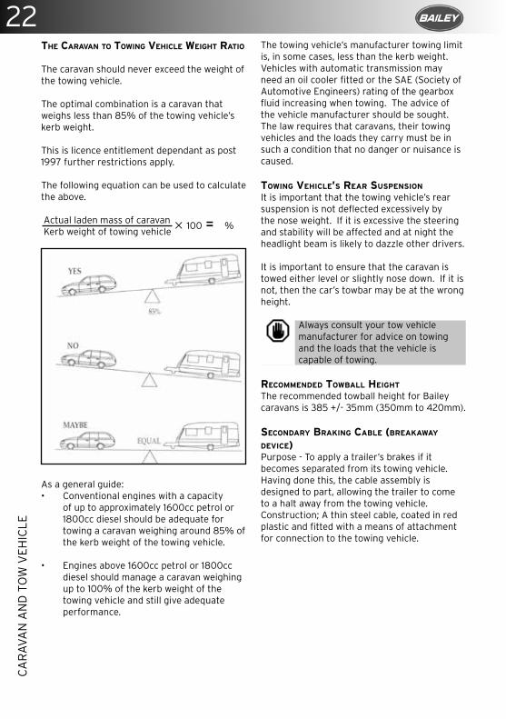
THE CARAVAN TO TOWING VEHICLE WEIGHT RATIO
The caravan should never exceed the weight of the towing vehicle.
The optimal combination is a caravan that weighs less than 85% of the towing vehicle’s kerb weight.
This is licence entitlement dependant as post 1997 further restrictions apply. The following equation can be used to calculate the above.
Actual laden mass of caravan Kerb weight of towing vehicle
As a general guide:• Conventional engines with a capacity
of up to approximately 1600cc petrol or 1800cc diesel should be adequate for towing a caravan weighing around 85% of the kerb weight of the towing vehicle.
• Engines above 1600cc petrol or 1800cc diesel should manage a caravan weighing up to 100% of the kerb weight of the towing vehicle and still give adequate performance.
The towing vehicle’s manufacturer towing limit is, in some cases, less than the kerb weight.Vehicles with automatic transmission may need an oil cooler fitted or the SAE (Society of Automotive Engineers) rating of the gearbox fluid increasing when towing. The advice of the vehicle manufacturer should be sought.The law requires that caravans, their towing vehicles and the loads they carry must be in such a condition that no danger or nuisance is caused.
TOWING VEHICLE’S REAR SUSPENSION
It is important that the towing vehicle’s rear suspension is not deflected excessively by the nose weight. If it is excessive the steering and stability will be affected and at night the headlight beam is likely to dazzle other drivers.
It is important to ensure that the caravan is towed either level or slightly nose down. If it is not, then the car’s towbar may be at the wrong height.
Always consult your tow vehicle manufacturer for advice on towing and the loads that the vehicle is capable of towing.
RECOMMENDED TOWBALL HEIGHT
The recommended towball height for Bailey caravans is 385 +/- 35mm (350mm to 420mm).
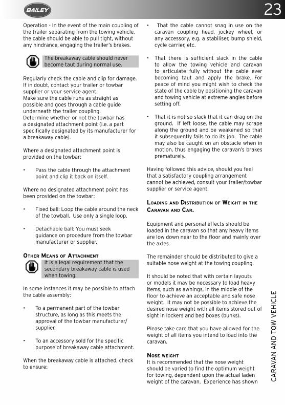
SECONDARY BRAKING CABLE (BREAKAWAY DEVICE)Purpose - To apply a trailer’s brakes if it becomes separated from its towing vehicle. Having done this, the cable assembly is designed to part, allowing the trailer to come to a halt away from the towing vehicle.Construction; A thin steel cable, coated in red plastic and fitted with a means of attachment for connection to the towing vehicle.
× 100 = %
23
CA
RAV
AN
AN
D T
OW
VEH
ICLE
Operation - In the event of the main coupling of the trailer separating from the towing vehicle, the cable should be able to pull tight, without any hindrance, engaging the trailer’s brakes.
The breakaway cable should never become taut during normal use.
Regularly check the cable and clip for damage. If in doubt, contact your trailer or towbar supplier or your service agent.Make sure the cable runs as straight as possible and goes through a cable guide underneath the trailer coupling.Determine whether or not the towbar has a designated attachment point (i.e. a part specifically designated by its manufacturer for a breakaway cable).
Where a designated attachment point is provided on the towbar:
• Pass the cable through the attachment point and clip it back on itself.
Where no designated attachment point has been provided on the towbar:
• Fixed ball: Loop the cable around the neck of the towball. Use only a single loop.
• Detachable ball: You must seek guidance on procedure from the towbar manufacturer or supplier.
OTHER MEANS OF ATTACHMENT
It is a legal requirement that the secondary breakaway cable is used when towing.
In some instances it may be possible to attach the cable assembly:
• To a permanent part of the towbar structure, as long as this meets the approval of the towbar manufacturer/supplier,
• To an accessory sold for the specific purpose of breakaway cable attachment.
When the breakaway cable is attached, check to ensure:
• That the cable cannot snag in use on the caravan coupling head, jockey wheel, or any accessory, e.g. a stabiliser, bump shield, cycle carrier, etc.
• That there is sufficient slack in the cable to allow the towing vehicle and caravan to articulate fully without the cable ever becoming taut and apply the brake. For peace of mind you might wish to check the state of the cable by positioning the caravan and towing vehicle at extreme angles before setting off.
• That it is not so slack that it can drag on the ground. If left loose, the cable may scrape along the ground and be weakened so that it subsequently fails to do its job. The cable may also be caught on an obstacle when in motion, thus engaging the caravan’s brakes prematurely.
Having followed this advice, should you feel that a satisfactory coupling arrangement cannot be achieved, consult your trailer/towbar supplier or service agent.
LOADING AND DISTRIBUTION OF WEIGHT IN THE CARAVAN AND CAR.
Equipment and personal effects should be loaded in the caravan so that any heavy items are low down near to the floor and mainly over the axles.
The remainder should be distributed to give a suitable nose weight at the towing coupling.
It should be noted that with certain layouts or models it may be necessary to load heavy items, such as awnings, in the middle of the floor to achieve an acceptable and safe nose weight. It may not be possible to achieve the desired nose weight with all items stored out of sight in lockers and bed boxes (bunks).
Please take care that you have allowed for the weight of all items you intend to load into the caravan.
NOSE WEIGHT
It is recommended that the nose weight should be varied to find the optimum weight for towing, dependent upon the actual laden weight of the caravan. Experience has shown
24C
AR
AVA
N A
ND
TO
W V
EHIC
LE
that the nose weight should be approximately 7% of the actual laden weight (i.e. between 50 and 100kg). However, this may be limited by the towing vehicle or caravan manufacturer’s limit nose weight. Check with the car handbook, or consult your retailer. The upper limit for the caravan coupling head is 100kg.
HITCHING UP
Before hitching up the vehicle always check the following:
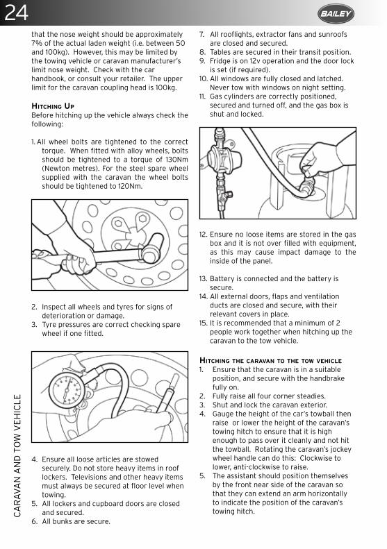
1. All wheel bolts are tightened to the correct torque. When fitted with alloy wheels, bolts should be tightened to a torque of 130Nm (Newton metres). For the steel spare wheel supplied with the caravan the wheel bolts should be tightened to 120Nm.
2. Inspect all wheels and tyres for signs of deterioration or damage.
3. Tyre pressures are correct checking spare wheel if one fitted.
4. Ensure all loose articles are stowed securely. Do not store heavy items in roof lockers. Televisions and other heavy items must always be secured at floor level when towing.
5. All lockers and cupboard doors are closed and secured.
6. All bunks are secure.
7. All rooflights, extractor fans and sunroofs are closed and secured.
8. Tables are secured in their transit position.9. Fridge is on 12v operation and the door lock
is set (if required).10. All windows are fully closed and latched.
Never tow with windows on night setting. 11. Gas cylinders are correctly positioned,
secured and turned off, and the gas box is shut and locked.
12. Ensure no loose items are stored in the gas box and it is not over filled with equipment, as this may cause impact damage to the inside of the panel.
13. Battery is connected and the battery is secure.
14. All external doors, flaps and ventilation ducts are closed and secure, with their relevant covers in place.
15. It is recommended that a minimum of 2 people work together when hitching up the caravan to the tow vehicle.
HITCHING THE CARAVAN TO THE TOW VEHICLE
1. Ensure that the caravan is in a suitable position, and secure with the handbrake fully on.
2. Fully raise all four corner steadies.3. Shut and lock the caravan exterior.4. Gauge the height of the car’s towball then
raise or lower the height of the caravan’s towing hitch to ensure that it is high enough to pass over it cleanly and not hit the towball. Rotating the caravan’s jockey wheel handle can do this: Clockwise to lower, anti-clockwise to raise.
5. The assistant should position themselves by the front near side of the caravan so that they can extend an arm horizontally to indicate the position of the caravan’s towing hitch.
25
CA
RAV
AN
AN
D T
OW
VEH
ICLE
6. Remove the car’s towball cover and keep it in a secure place in the car.
7. Slowly reverse the towing vehicle towards the caravan. When reversing the towing vehicle towards the caravan always ensure that any pedestrians and your assistant are visible at all times.
8. When reversing aim the towball of the car directly at the caravan towing hitch.
9. When the car’s towball is as near to the caravan’s towing hitch as possible fully apply the car’s handbrake, turn off the engine and leave the car in first gear (Park or ‘P’ position for automatics).
10. Carefully release the caravan’s handbrake.11. Manoeuvre the caravan’s tow hitch directly
over the towing vehicle’s tow ball. Always manoeuvre the vehicle by pushing/pulling on the grab handles. When the caravan is in the correct position fully apply the handbrake.
12. Raise the handle on the caravan tow hitch until it clicks and remains at an angle.
13. Rotate the jockey wheel handle clockwise to lower the hitch onto the towball. When the tow hitch clicks and the handle drops to the horizontal position it is engaged. The hitch head is fitted with a visual indicator on the front radius to show whether or not it is properly connected to the tow ball. A green band will show immediately below the red indicator button on the hitch head when a proper connection has been made.
14. Connect secondary braking cable as per the instructions in the previous section.
15. Test that the hitch is now fully engaged by slightly raising the caravan hitch from the car towball by winding the jockey wheel handle anti-clockwise. The hitch should not release from the car towball. Only raise the rear of the car enough to check the hitch is fully engaged. See Alko manual for furhter information on hitching up, unhitching and fault identificatio.
16. Turn the jockey wheel winding handle to lower the caravan. When the wheel is fully retracted, release the clamp and raise the jockey wheel to travel position.
17. Once the jockey wheel is in travel position and the wheel is located in the recess, tighten the clamp again.
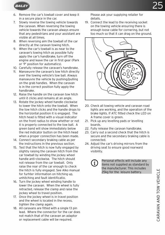
18. All caravans are fitted with a single 13 pin lead. Where the connector for the car does not match that of the caravan an adaptor or replacement cable will be required.
Please ask your supplying retailer for details.
19. Connect the lead to the receiving socket on the towing vehicle ensuring there is enough loose cable for cornering, but not too much so that it can drag on the ground.
20. Check all towing vehicle and caravan road lights are working, and the operation of the brake lights. If ATC fitted check the LED on A frame cover is green.
21. Pick up any levelling pads or levelling boards.
22. Fully release the caravan handbrake.23. Carry out a second check that the hitch is
secure and the secondary braking cable is connected.
24. Adjust the car’s driving mirrors from the driving seat to ensure good rearward visibility.
Personal effects will include any items not supplied as standard by the manufacturer. This includes 25kg for the leisure battery.
26C
AR
AVA
N A
ND
TO
W V
EHIC
LE
TOWING
TOWING VEHICLES
Your new caravan is designed to be towed by a normal motor car.If you intend to tow it with a Pick-up type vehicle, car derived van or a 4x4 vehicle additional care should be exercised due to the potential of harder rear suspension imposing excessive loads/force onto the caravan. You may also have to adjust your driving style over rough terrain. Particular attention should be given to the height of the tow ball in relation to the caravan coupling.
Your new caravan should not be towed by a commercial vehicle with a gross vehicle weight in excess of over 3500kgs.
When selecting a towing vehicle, it is recommended that you consult the Caravan Towing Guide which is available form the NCC.
SPEED LIMITS
Where a lower limit is not in force, caravans may be towed at up to a maximum of 50 mph on single carriageways or 60 mph on dual carriageways and motorways. For further information on towing regulations can be found in the Highway Code.
PULLING AWAY
• Allow more engine speed to produce the power to move the additional weight of the caravan.
• Always let the clutch out smoothly, to avoid wear and tear on the clutch plate and transmission.
• Change gears smoothly. Ensure optimum revs are always used when changing gears.
• Try not to drop the clutch.
CARAVAN HANDLING
• Make allowances for the caravan being slightly wider than the car.
• Allow additional distance from the kerb with caravan wheels so that they are not “kerbed”.
• When passing other vehicles allow more than normal clearance for driving solo.
• Overtaking and stopping distances are increased when you are towing.
• Always indicate in plenty of time before carrying out any manoeuvre.
• Allow longer to accelerate up to speed prior to overtaking.
• Allow for the vehicle being twice its normal length.
• Do not suddenly swing out.• Carry out all manoeuvres as smoothly as
possible.
REVERSING
Skilled reversing can only be achieved with practice and should be first attempted in an open area. Consider a suitable training course.
MOTORWAY DRIVING
Caravans may not be towed in the outside lane of three or four lane Motorways (Reg 12(2) of the motorway Traffic [England and Wales] Regulations 1982).Reduce speed in high winds, cross winds, driving downhill or in poor visibility.High-sided vehicles such as lorries or coaches can cause air buffeting, so extra care must be taken when passing or being passed. Give as much space as is possible between your caravan and the high-sided vehicle.
MIRRORS
The law requires the driver of the towing vehicle to have an adequate view to the rear.If there is no rear-view through the caravan windows it may be necessary to have additional exterior towing mirrors fitted to provide a view along both sides of the caravan. In some countries these additional mirrors are a legal requirement.Any rear view mirror must not project more than 200mm outside:
• The width of the caravan when being towed.• The width of the towing vehicle when driven
solo.Any additional rear-view mirror fitted shall be of an approved European type and cover the field of view as stipulated by the regulators.
Passengers are forbidden to ride in a caravan at any time.
SNAKING
This is a term used to denote an unstable car and caravan combination where the caravan “weaves” from side to side often causing a similar swaying movement in the car itself. Possible causes are:
• Insufficient tyre pressure on either the caravan or the tow vehicle.
• Tow vehicle is too light.
27
CA
RAV
AN
AN
D T
OW
VEH
ICLE
• Incorrect loading or weight distribution.• Excessive speed especially downhill.• Side winds.• Overtaking.• Being overtaken by a high-sided vehicle.• Erratic driving.• Mixing radial and cross ply tyres.• Nose of the caravan is towing too high.• Insufficient nose weight.
STABILISERS
A stabiliser should never be used to try to improve a caravan/towing vehicle combination that has poor stability as instability may appear at high speed.However, a good stabiliser can make an acceptable caravan and towing vehicle combination more comfortable and easier to handle.
Holes should not be drilled in either the coupling head or A frame members without prior consultation with the chassis manufacturer.
If you encounter snaking, try to keep the steering wheel in a central position, slow down gently and avoid braking if possible.
ROAD LIGHTING
All caravans are fitted with a single 13 pin lead. When the connector for the car does not match that of the caravan an adaptor or replacement cable will be required. Please ask your supplying retailer for more information.
It is important that all the road lights on your Bailey caravan are checked before you set out on a journey.
All lights must be working in the correct manner for the vehicle to be road legal.
Clean the outside of the lights with a non-abrasive or non-aggressive cleaning solution on a regular basis. Always replace a lamp which is showing any sign of damage.
13 PIN PLUG
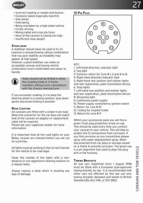
KEY:1. Left-hand direction, indicator light2. Fog light3. Common return for Core # 1, 2 and 4 to 8.4. Right-hand direction indicator light5. Right-hand rear position and marker lights and rear registration, plate illumination device.6. Stop lights7. Left-hand rear position and marker lights and rear registration, plate illumination device8. Reversing light9. Continuous power supply10. Power supply controlled by ignition switch11. Return for core # 1012. Coding for coupled trailer13. Return for core # 9
Within your accessories pack you will find a green 13 pin plug protection screw on cap. This should be used every time you connect your caravan to your vehicle. This will help to protect the 13 connections from corrosion. If you find corrosion on you connections please spray with water displacement spray. When disconnected from car place in storage socket on A frame to prevent corrosion. The green cap is a pin alignment tool used to align the plug pins in the housing.
TOWING BRACKETS
All tow cars registered since 1 August 1998 must be fitted with a European type-approved towing bracket, by law. It is recommended that other cars not affected by this law use only towing brackets designed and tested to British Standard BS (AU) 114b, or ISO 3853.

28Truma iNet System – everything under controlUpgrade your Bailey Pegasus for Ultimate comfortFor extra comfort and convenience, manage your air conditioning, heating and check your gas levels precisely and conveniently from your smartphone.
www.trumauk.com/inet
TRU18002_iNet_System_Bailey_Handbook_148_210_EN_RZ.indd 1 07.09.18 12:49
29
UN
HIT
CH
ING
Truma iNet System – everything under controlUpgrade your Bailey Pegasus for Ultimate comfortFor extra comfort and convenience, manage your air conditioning, heating and check your gas levels precisely and conveniently from your smartphone.
www.trumauk.com/inet
TRU18002_iNet_System_Bailey_Handbook_148_210_EN_RZ.indd 1 07.09.18 12:49
UNHITCHING
• Do not pitch in a position in which your outfit will obstruct other people.
• Try to choose an area that is dry, reasonably level and preferably on hard standing ground.
• If you have no alternative but to pitch on a slope, ensure that you are facing down the slope for when you leave.
• It is good practice to chock the wheels of the caravan when parked on a slope even when the caravan brakes are applied.
PROCEDURE
1. Fully apply the caravan handbrake.2. Unclasp and lower the jockey wheel
to the ground.3. Re-clamp it in this position. 4. Pull the stabiliser lever up as far
as it will go, open the coupling handle and lift from the towball. With larger nose loads, coupling and uncoupling can be made easier by using the jockey wheel to assist lifting.
5. Re-clamp jockey wheel if necessary.6. Disconnect the secondary braking
cable.7. Disconnect the 13 pin plug and return
it to its holder.8. Replace towball cover.9. Park your vehicle alongside the
caravan on the offside.
Serious damage will occur unless the button is depressed first and the handle lifted forward before the caravan is lifted manually. This prevents the nose weight being transmitted through the button.
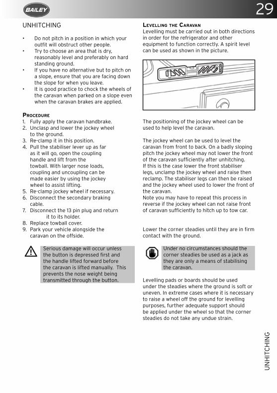
LEVELLING THE CARAVAN
Levelling must be carried out in both directions in order for the refrigerator and other equipment to function correctly. A spirit level can be used as shown in the picture.
The positioning of the jockey wheel can be used to help level the caravan.
The jockey wheel can be used to level the caravan from front to back. On a badly sloping pitch the jockey wheel may not lower the front of the caravan sufficiently after unhitching. If this is the case lower the front stabiliser legs, unclamp the jockey wheel and raise then reclamp. The stabiliser legs can then be raised and the jockey wheel used to lower the front of the caravan.Note you may have to repeat this process in reverse if the jockey wheel can not raise front of caravan sufficiently to hitch up to tow car.
Lower the corner steadies until they are in firm contact with the ground.
Under no circumstances should the corner steadies be used as a jack as they are only a means of stabilising the caravan.
Levelling pads or boards should be used under the steadies where the ground is soft or uneven. In extreme cases where it is necessary to raise a wheel off the ground for levelling purposes, further adequate support should be applied under the wheel so that the corner steadies do not take any undue strain.
30W
HEE
LS A
ND
TY
RES
with a natural material (e.g. hessian) for protection but NOT plastic materials. This will reduce the deterioration of the tyres and reduce the cracking and flat spots caused by continuous loading and external conditions. It is recommended to protect tyres from direct sunlight.
If it is not practical to remove the wheels it is recommended to routinely rotate the wheels to reduce the potential of cracking, flat spots etc.
Check with your insurance company that you are still covered when the wheels are removed.
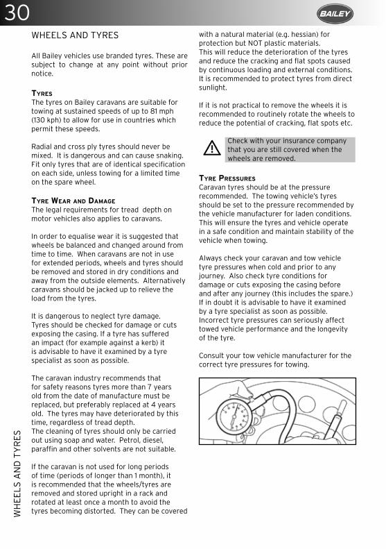
TYRE PRESSURES
Caravan tyres should be at the pressure recommended. The towing vehicle’s tyres should be set to the pressure recommended by the vehicle manufacturer for laden conditions. This will ensure the tyres and vehicle operate in a safe condition and maintain stability of the vehicle when towing.
Always check your caravan and tow vehicle tyre pressures when cold and prior to any journey. Also check tyre conditions for damage or cuts exposing the casing before and after any journey (this includes the spare.) If in doubt it is advisable to have it examined by a tyre specialist as soon as possible. Incorrect tyre pressures can seriously affect towed vehicle performance and the longevity of the tyre.
Consult your tow vehicle manufacturer for the correct tyre pressures for towing.
WHEELS AND TYRES
All Bailey vehicles use branded tyres. These are subject to change at any point without prior notice.
TYRES
The tyres on Bailey caravans are suitable for towing at sustained speeds of up to 81 mph (130 kph) to allow for use in countries which permit these speeds.
Radial and cross ply tyres should never be mixed. It is dangerous and can cause snaking. Fit only tyres that are of identical specification on each side, unless towing for a limited time on the spare wheel.
TYRE WEAR AND DAMAGE
The legal requirements for tread depth on motor vehicles also applies to caravans.
In order to equalise wear it is suggested that wheels be balanced and changed around from time to time. When caravans are not in use for extended periods, wheels and tyres should be removed and stored in dry conditions and away from the outside elements. Alternatively caravans should be jacked up to relieve the load from the tyres.
It is dangerous to neglect tyre damage. Tyres should be checked for damage or cuts exposing the casing. If a tyre has suffered an impact (for example against a kerb) it is advisable to have it examined by a tyre specialist as soon as possible.
The caravan industry recommends that for safety reasons tyres more than 7 years old from the date of manufacture must be replaced, but preferably replaced at 4 years old. The tyres may have deteriorated by this time, regardless of tread depth.The cleaning of tyres should only be carried out using soap and water. Petrol, diesel, paraffin and other solvents are not suitable.
If the caravan is not used for long periods of time (periods of longer than 1 month), it is recommended that the wheels/tyres are removed and stored upright in a rack and rotated at least once a month to avoid the tyres becoming distorted. They can be covered
31
WH
EELS
AN
D T
YR
ES
WHEELS
Caravan wheel bolts must only be tightened to the appropriate setting by tightening each opposite fixing in succession to the correct torque. Always use a calibrated torque wrench. Do not use a corner steady brace, power or electric wrench. It is as dangerous to over-tighten bolts as it is to not tighten them sufficiently.
The torque settings should be checked after the first 50km/30 miles. For alloy wheels the wheel bolts should be tightened to a torque of 130Nm (Newton metres) (96 lb-ft). For steel wheels the wheel bolts should be tightened to a torque of 120Nm (88 lb-ft)
The condition of wheels should be checked regularly, particularly for distortion of flanges and the wheel dish. Damaged or distorted wheels, or having the wheel bolt seating cracked or deformed, must not be repaired.
If a wheel or tyre has to be changed it should be of the same type of construction and size as originally fitted.
Only use a spare wheel and tyre recommended by Bailey Caravans, which should be of the same specification as those fitted to the caravan.
Always ensure mating surfaces and bolt seating areas are clean and dry. Wheel bolts should never be lubricated.
SPARE WHEELS
Spare wheels are available with some models.
The spare wheel fitted to your caravan is an unbranded tyre.
1. Always ensure that the tow vehicle and caravan are in a safe position before attempting to change the caravan’s wheel. We recommend leaving the caravan hitched to the tow vehicle when changing a wheel. The tow vehicle should be left in gear (or “P”/Park for an automatic) with the handbrake on both the car and the caravan fully applied.
2. Lower the corner steadies as a safety measure to stabilise the caravan. Chock the unpunctured wheel on the opposite side of the caravan to prevent any movement.
3. Slacken off the wheel bolts by no more than one quarter of a turn on the wheel that requires changing. Do not fully undo them.
4. We recommend you only use an AL-KO jack on the AL-KO chassis. Please refer to your AL-KO handbook for jacking instructions.
5. The wheel that is to be removed should be lifted just off the ground.
6. Remove the wheel bolts and remove the wheel.
7. Fit the spare wheel, and reverse the above procedure. Ensure the wheel bolts are all fitted, and tightened in the correct sequence. Ensure correct torque setting.
8. Remember to check the torque of wheel bolts after 50kms/30 miles.
Under no circumstances should the corner steadies be used as a jack. They are only a means of stabilising the caravan.
SPARE WHEEL CARRIER The spare wheel carrier fitted in your leisure vehicle (model specific) is much like that fitted onto a car.
TO LOWER THE SPARE WHEEL:1. Remove the plastic stopper in the floor. 2. The winder for the spare wheel carrier
can be found in the kit bag supplied with the vehicle.
3. Remove the winder from the kit bag and insert the hooked end of the crank in the spare wheel retaining attachment.
4. Lower the spare wheel to the ground, with a little amount of slack. Pull the wheel out as far as possible before slackening the cable further. Repeat until the wheel is in the desired position.
5. Draw the spare wheel towards you from under the leisure vehicle.
6. Pivot the toggle at the end of the cable 90 degrees to release it from the spare wheel.
7. Crank up the cable again by turning the crank clockwise.
32W
HEE
LS A
ND
TY
RES
RETURNING THE SPARE WHEEL TO THE STORAGE COMPARTMENT:1. Use the crank to lower the spare wheel’s
retaining cable. When there is no wheel attached, the cable will need to be gently pulled from the carrier.
2. Pass the toggle at the end of the cable through the centre hole in the spare wheel. Pivot the toggle 90 degrees so that when raised, the wheel will rest on the toggle.
3. Retract the retaining cable slightly by slowly turning the crank clockwise several times.
4. Position the wheel so that it is not obstructed by components under the floor.
5. Continue to raise the wheel by turning the crank clockwise. Raise the wheel a little bit at a time and guide it until it is securely seated against the floor.
6. When it is no longer possible to turn the crank, check that the spare wheel is seated tight against the underside of the floor.
7. Replace the plastic stopper insid the vehicle.
TPMS TYRE PRESSURE MONITORING SYSTEM
(SUPPLIED WITH CERTAIN MODELS OF BAILEY CARAVAN)This system is designed to monitor the pressure and temperature of wheels and tyres that have been fitted with TyrePal TPMS internal sensors. Additional sensors can be purchased to monitor spare wheels, or the tyres on the towing car.
The system continuously monitors tyre pressure and temperature while the caravan is in motion and gives distinct alerts in the event of:• Rapid pressure loss• Low tyre pressure • High tyre pressure • High tyre temperature The system can monitor up to 22 tyres on a car and trailer.
The system does not replace the need to carry out regular checks on the condition, age and wear of tyres.
For full details and instruction on how to use/set up your TPMS please see the manual supplied with the unit.

Contact usCustomer Services
Call us
01543 870 190
www.tyrepal.co.uk/tyrepalTPMS@tyrepal/tyrepal-ltd
For further information, please visit: www.tyrepal.co.uk
SAVES FUEL, SAVES TYRES, SAVES LIVES
Tyre Pressure Monitoring Systems pay for themselves by reducing tyre-related breakdowns as well as improving fuel economy and tyre life.
Did you know the Bailey Unicorn range comes fully equipped with TyrePal tyre pressure monitoring as standard?
TyrePal TPMS continuously monitors the pressures and temperatures of your tyres and warns you if things are going wrong.
It is simple to add TyrePal TPMS to your Pegasus or Pursuit caravan, contact Bailey Parts Direct or your dealership for details.

Quality online print
bannersvinylspostersstickerswallpapercorrexfoamexcheck us out now to see more

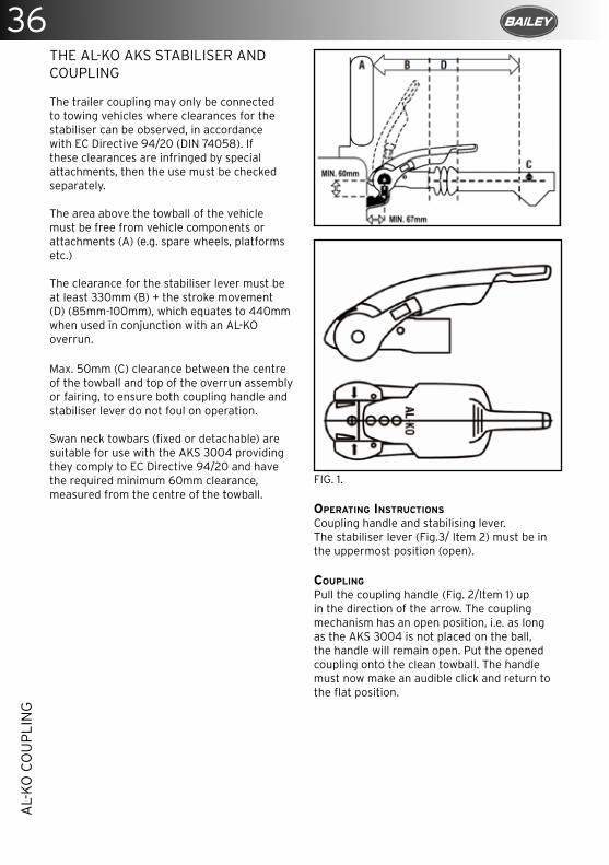
36A
L-K
O C
OU
PLI
NG
THE AL-KO AKS STABILISER AND COUPLING
The trailer coupling may only be connected to towing vehicles where clearances for the stabiliser can be observed, in accordance with EC Directive 94/20 (DIN 74058). If these clearances are infringed by special attachments, then the use must be checked separately.
The area above the towball of the vehicle must be free from vehicle components or attachments (A) (e.g. spare wheels, platforms etc.)
The clearance for the stabiliser lever must be at least 330mm (B) + the stroke movement (D) (85mm-100mm), which equates to 440mm when used in conjunction with an AL-KO overrun.
Max. 50mm (C) clearance between the centre of the towball and top of the overrun assembly or fairing, to ensure both coupling handle and stabiliser lever do not foul on operation.
Swan neck towbars (fixed or detachable) are suitable for use with the AKS 3004 providing they comply to EC Directive 94/20 and have the required minimum 60mm clearance, measured from the centre of the towball.
FIG. 1.
OPERATING INSTRUCTIONS
Coupling handle and stabilising lever.The stabiliser lever (Fig.3/ Item 2) must be in the uppermost position (open).
COUPLING
Pull the coupling handle (Fig. 2/Item 1) up in the direction of the arrow. The coupling mechanism has an open position, i.e. as long as the AKS 3004 is not placed on the ball, the handle will remain open. Put the opened coupling onto the clean towball. The handle must now make an audible click and return to the flat position.
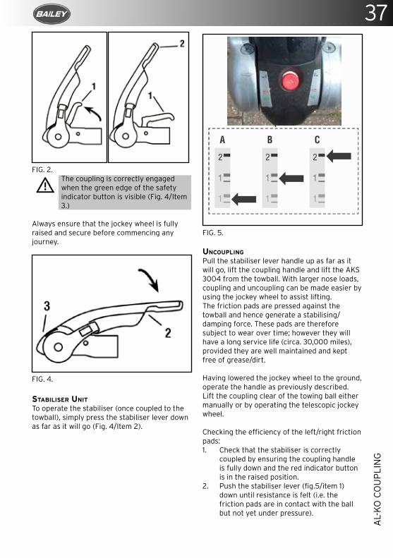
37
AL-
KO
CO
UP
LIN
G
FIG. 2. The coupling is correctly engaged when the green edge of the safety indicator button is visible (Fig. 4/Item 3.)
Always ensure that the jockey wheel is fully raised and secure before commencing any journey.
FIG. 4.
STABILISER UNIT
To operate the stabiliser (once coupled to the towball), simply press the stabiliser lever down as far as it will go (Fig. 4/Item 2).
FIG. 5.
UNCOUPLING
Pull the stabiliser lever handle up as far as it will go, lift the coupling handle and lift the AKS 3004 from the towball. With larger nose loads, coupling and uncoupling can be made easier by using the jockey wheel to assist lifting. The friction pads are pressed against the towball and hence generate a stabilising/damping force. These pads are therefore subject to wear over time; however they will have a long service life (circa. 30,000 miles), provided they are well maintained and kept free of grease/dirt.
Having lowered the jockey wheel to the ground, operate the handle as previously described. Lift the coupling clear of the towing ball either manually or by operating the telescopic jockey wheel.
Checking the efficiency of the left/right friction pads:1. Check that the stabiliser is correctly
coupled by ensuring the coupling handle is fully down and the red indicator button is in the raised position.
2. Push the stabiliser lever (fig.5/item 1) down until resistance is felt (i.e. the friction pads are in contact with the ball but not yet under pressure).
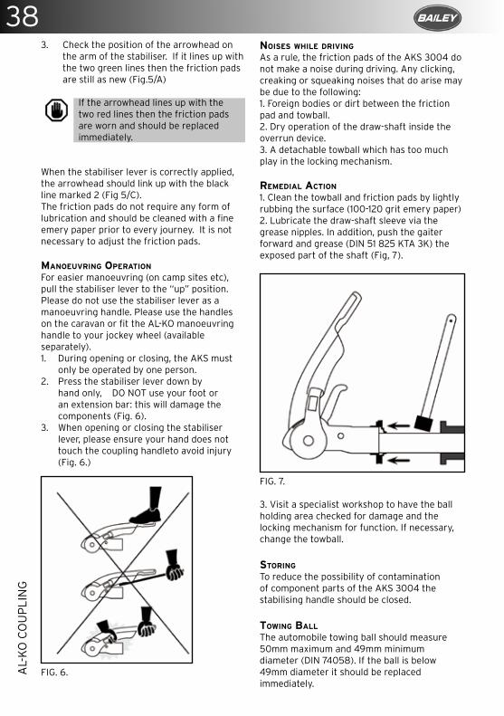
38A
L-K
O C
OU
PLI
NG
3. Check the position of the arrowhead on the arm of the stabiliser. If it lines up with the two green lines then the friction pads are still as new (Fig.5/A)
If the arrowhead lines up with the two red lines then the friction pads are worn and should be replaced immediately.
When the stabiliser lever is correctly applied, the arrowhead should link up with the black line marked 2 (Fig 5/C).The friction pads do not require any form of lubrication and should be cleaned with a fine emery paper prior to every journey. It is not necessary to adjust the friction pads.
MANOEUVRING OPERATION
For easier manoeuvring (on camp sites etc), pull the stabiliser lever to the “up” position. Please do not use the stabiliser lever as a manoeuvring handle. Please use the handles on the caravan or fit the AL-KO manoeuvring handle to your jockey wheel (available separately).1. During opening or closing, the AKS must
only be operated by one person. 2. Press the stabiliser lever down by
hand only, DO NOT use your foot or an extension bar: this will damage the components (Fig. 6).
3. When opening or closing the stabiliser lever, please ensure your hand does not touch the coupling handleto avoid injury (Fig. 6.)
FIG. 6.
NOISES WHILE DRIVING
As a rule, the friction pads of the AKS 3004 do not make a noise during driving. Any clicking, creaking or squeaking noises that do arise may be due to the following:1. Foreign bodies or dirt between the friction pad and towball. 2. Dry operation of the draw-shaft inside the overrun device. 3. A detachable towball which has too much play in the locking mechanism.
REMEDIAL ACTION
1. Clean the towball and friction pads by lightly rubbing the surface (100-120 grit emery paper)2. Lubricate the draw-shaft sleeve via the grease nipples. In addition, push the gaiter forward and grease (DIN 51 825 KTA 3K) the exposed part of the shaft (Fig, 7).
FIG. 7.
3. Visit a specialist workshop to have the ball holding area checked for damage and the locking mechanism for function. If necessary, change the towball.
STORING
To reduce the possibility of contamination of component parts of the AKS 3004 the stabilising handle should be closed.
TOWING BALL
The automobile towing ball should measure 50mm maximum and 49mm minimum diameter (DIN 74058). If the ball is below 49mm diameter it should be replaced immediately.
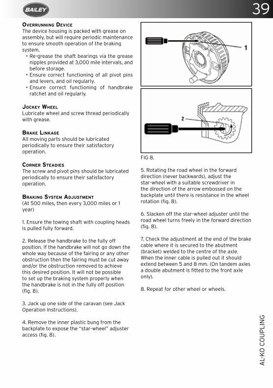
39
AL-
KO
CO
UP
LIN
G
OVERRUNNING DEVICE
The device housing is packed with grease on assembly, but will require periodic maintenance to ensure smooth operation of the braking system.
• Re-grease the shaft bearings via the grease nipples provided at 3,000 mile intervals, and before storage.
• Ensure correct functioning of all pivot pins and levers, and oil regularly.
• Ensure correct functioning of handbrake ratchet and oil regularly.
JOCKEY WHEEL
Lubricate wheel and screw thread periodically with grease.
BRAKE LINKAGE
All moving parts should be lubricated periodically to ensure their satisfactory operation.
CORNER STEADIES
The screw and pivot pins should be lubricated periodically to ensure their satisfactory operation.
BRAKING SYSTEM ADJUSTMENT
(At 500 miles, then every 3,000 miles or 1 year)
1. Ensure the towing shaft with coupling heads is pulled fully forward.
2. Release the handbrake to the fully off position. If the handbrake will not go down the whole way because of the fairing or any other obstruction then the fairing must be cut away and/or the obstruction removed to achieve this desired position. It will not be possible to set up the braking system properly when the handbrake is not in the fully off position (fig. 8).
3. Jack up one side of the caravan (see Jack Operation Instructions).
4. Remove the inner plastic bung from the backplate to expose the “star-wheel” adjuster access (fig. 8).
FIG 8.
5. Rotating the road wheel in the forward direction (never backwards), adjust the star-wheel with a suitable screwdriver in the direction of the arrow embossed on the backplate until there is resistance in the wheel rotation (fig. 8).
6. Slacken off the star-wheel adjuster until the road wheel turns freely in the forward direction (fig. 8).
7. Check the adjustment at the end of the brake cable where it is secured to the abutment (bracket) welded to the centre of the axle. When the inner cable is pulled out it should extend between 5 and 8 mm. (On tandem axles a double abutment is fitted to the front axle only).
8. Repeat for other wheel or wheels.
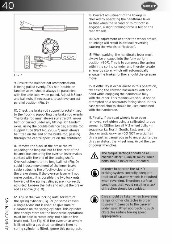
40A
L-K
O C
OU
PLI
NG
FIG 9.
9. Ensure the balance bar (compensation) is being pulled evenly. This bar (double on tandem axles) should always be paralleled with the axle tube when pulled. Adjust M8 lock and ball nuts, if necessary, to achieve correct parallel position (Fig. 9)
10. Check the brake rod support bracket (fixed to the floor) is supporting the brake rod evenly. The brake rod must always run straight, never bent or curved under any fittings. On tandem axles, using the double balance bar, a brake rod support tube (Part No. 228827) must always be fitted on the end of the brake rod, passing through the centre aperture on the abutment.
11. Remove the slack in the brake rod by adjusting the long ball nut to the rear of the balance bar, ensuring the overrun lever makes contact with the end of the towing shaft. Over-adjustment to the long ball nut (Fig.10) could induce movement of the inner brake cable, reducing the effective clearance of the brake shoes. If the overrun lever will not make contact, it is possible the two lock nuts, forward of the spring cylinder, are incorrectly adjusted. Loosen the nuts and adjust the brake rod as above (Fig. 8).
12. Adjust the two locking nuts, forward of the spring cylinder (Fig. 9) (on some chassis a single Nyloc nut is used) to give 1mm of clearance on the spring cylinder. This cylinder (the energy store for the handbrake operation) must be able to rotate only, not slide on the brake rod. (See Fig. 9) If the overrun assembly is fitted with a gas strut handbrake then no spring cylinder is fitted, ignore this paragraph.
13. Correct adjustment of the linkage is checked by operating the handbrake lever so that when the second or third tooth is engaged, a slight braking force is felt on the road wheels.
14.Over-adjustment of either the wheel brakes or linkage will result in difficult reversing causing the wheels to “lock-up”.
15. When parking, the handbrake lever must always be engaged into the fully upright position (90°). This is to compress the spring within the spring cylinder and thereby create an energy store, which will automatically engage the brakes further should the caravan move.
16. If difficulty is experienced in this operation, try easing the caravan backwards with one hand while engaging the handbrake fully with the other. This manoeuvre should not be attempted on a rearwards facing slope. In this case wheel chocks should be used combined with the handbrake.
17. Finally, if the road wheels have been removed, re-tighten using a calibrated torque wrench to 130Nm (on all M12 wheel bolts - in sequence, i.e. North, South, East, West not clock or anticlockwise.) DO NOT overtighten this is just as dangerous as to undertighten, as this can distort the wheel rims. Avoid the use of power wrenches.
The torque settings should be re-checked after 50km/30 miles. Wheel bolts should never be lubricated.
In order to operate the AL-KO braking system correctly adequate traction of caravan wheels is required when reversing. Therefore surface conditions that would result in a lack of traction should be avoided.
Care should be taken when traversing ramps or other obstacles in order to prevent damage to the caravan under gear. When approaching such obstacles reduce towing speed appropriately.
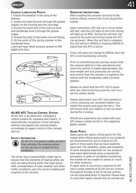
41
AL-
KO
CO
UP
LIN
G
CHASSIS LUBRICATION POINTS
1. Grease the drawbar in the area of the bellows.2. Grease the bearing bush through the grease nipples on the housing and the cartridge.3. Grease the pivot bolt of the overrun lever and handbrake levers through the grease nipple.4. Grease the joint of the brake rod and fitting.5. Oil the joints of the spring cylinder in the handbrake lever.Lubricant type: Multi-purpose grease to DIN 51825 KTA 3K4.
AL-KO ATC TRAILER CONTROL SYSTEM
AL-KO ATC is an electronic, emergency control system for caravans and trailers. It automatically recognises critical swinging motions and applies the caravan brakes accordingly to regain control of the caravan and car.
SAFETY INFORMATION
AL-KO ATC is a passive safety product that activates the braking system on the caravan in unsafe driving conditions.
The driver has a responsibility under law to ensure that the elements of towing safety are met, including driving within the legal speed limit, consideration of road, weather and other traffic conditions, also the correct loading and coupling of the caravan.
OPERATING INSTRUCTIONS
After coupling the caravan correctly to the towing vehicle, connect the 13 pin plug to the towbar.
Upon connection, ATC will carry out an initial self test and the LED light on the front fairing will light up on RED. During the self test, the sound of the push rod moving inside the ATC can be heard. When the self test is complete, the LED will turn GREEN or flashing GREEN to signal that the ATC is active.
If the LED does not change to GREEN, then the ATC is not functioning correctly.
Prior to commencing any journey, ensure that the caravan lighting is fully operational and check the vehicle is loaded appropriately, the nose weight and tyre pressures are correct, and confirm that the caravan is coupled to the vehicle with the breakaway cable correctly applied.
Always re-check that the ATC LED is green after any interval during a journey, such as a service station break.
Always disconnect your ATC once parked on a ferry, ensuring you reconnect before you restart the engine and leave the ferry. This will ensure that your battery is not run down during the crossing.
Should you experience any issues with your ATC please contact AL-KO or the supplying Bailey retailer.
SPARE PARTS
Spare parts are safety critical parts! For this reason when fitting spare parts in our products we recommend the use of original AL-KO parts or those parts that we have explicitly approved. The reliability, safety and suitability of parts designed especially for our products have been determined using a special test procedure. In spite of constantly monitoring the market we are unable to assess or vouch for other products.If repair work or servicing is required AL-KO have a large network of AL-KO service centres throughout Europe. A list of service centres can be requested direct if required. Please bear in mind that repairs should only be carried out
42A
L-K
O C
OU
PLI
NG
by trained and qualified workshops/personnel. To establish the correct spare parts the service centres need the ETI number (spare part identification number). CHASSIS MEMBERS
The recommended tow vehicle coupling height is 385mm +/- 35mm from the ground to the centre of the ball.
Off road vehicles are exempt from this towball height specification.
Manufactured from high quality steel, the chassis has extra deep sections to provide strength at points of maximum stress. Large elongated holes are punched in the longitudinal and towbar (A frame) members, to reduce weight to a minimum. Each hole incorporates a return flange to maintain the required strength and provide rigidity in the extra deep sections.
The chassis frame is of a bolted construction which, should the need arise, allows replacement of individual parts.
The chassis is hot dipped galvanized. This is regarded as one of the best forms of corrosion protection. It does, however, require maintenance in certain circumstances.When new, the chassis is of a bright and shining appearance. As the galvanizing cures during the initial 2- 3-month period, this will gradually change. During this curing period the surface should be protected to avoid possible wet storage stain, a soft, light coloured, porous, oxidation layer. If the chassis members are in contact with any salt deposits from roads they should be washed off immediately with a high pressure washer. Salt attracts moisture allowing the surfaces to remain wet. This prevents curing and also allows formation of wet storage stain.
It is recommended that the chassis be washed off, using a pressure washer, on an annual basis (particularly after winter usage) to avoid undesirable build up of salt and dirt deposits.
Do not spray or direct wet jet into the floor vents and other openings. Do Not pressure wash the sides or roof of the caravan to aviod ingress of water through roof lights, windows and fridge vents.
The galvanized chassis should not be painted or subjected to any other protective treatment. Should the galvanizing become superficially damaged exposing the steel core, then it should be cleaned and treated with a cold galvanizing spray.Damage to chassis members through impact etc. must not be straightened or welded. Damaged chassis members must be replaced.
DRILLING OR WELDING OF PARTS OR ACCESSORIES
This chassis is designed and built to precise tolerances and must not be drilled or welded.
INDEPENDENT SUSPENSION
The AL-KO rubber suspension is designed and developed to suit all types of road conditions and is maintenance-free. Three rubber elements are contained within a hexagonal axle tube. These provide suspension and have inherent damping characteristics. (Only the hubs and wheel brakes require attention, see axle booklet Part No. 580458.)
COUPLING HEAD
The ball couplings are entirely automatic in operation and designed for one-hand operation to suit the 50mm international ball recommended by the British Standards Institution, National Caravan Council and the Society of Motor Manufacturers and Traders.
BRAKE DRUM/HUB ASSEMBLY
The Euro Axle fitted to your Bailey caravan comes complete with maintenance-free wheel bearings greased and serviced for life. Adjustment is not required during the design life of the sealed bearing (100,000 km).
If replacement of the brake drum or shoes is required, this must be carried out by authorised AL-KO Service Centres. Specialist tools and equipment are required. The rear hexagonal bolt covered by a black plastic cover must NEVER be touched.
43
TRA
CK
ER M
ON
ITO
R &
CA
RAV
AN
ALA
RM
TRACKER MONITOR AND CARAVAN ALARM
Dependant upon model, your caravan may have been fitted with a TRACKER Monitor and Caravan Alarm.Using VHF technology, the police can track a stolen caravan even if it’s being transported or hidden in a lock-up or a shipping container.
ALARM OPERATING INSTRUCTIONS
The Caravan Alarm system detects external caravan movement such as shaking and tilting, lifting and towing. Internal movement is detected by a passive infrared sensor (PIR).
If the alarm is triggered, the siren will sound.The TRACKER Monitor system, once armed via the remote control, detects caravan motion. If the TRACKER Monitor system is triggered, TRACKER will be alerted. TRACKER will call you and, if there has been a theft, start the recovery process.
TRACKER Monitor requires a setting period of 2 minutes before becoming fully operational.Should the alarm not be armed or not be operational at any point (e.g. as the result of a flat remote control battery), the TRACKER Monitor system will still continue to operate for tracking and recovery purposes but no automatic alert will be given to TRACKER.
TO ARM
Press the button on the remote control once and the siren will beep twice.After 45 seconds the alarm will be armed.The siren will be triggered if the caravan is towed, moved, tilted and lifted onto the back of a trailer.The siren will sound for five minutes unless stopped by the user. The siren can also be trig-gered by the passive infrared detector (PIR).
TO DISARM
Press the button on the remote control once. The siren will beep once and the alarm will disarm. If already sounding, the siren will be silenced.The alarm is supplied with one PIR and two remote control units. Additional units may be ordered from your Bailey retailer.
WINTER STORAGE
Before storing the caravan for winter, please ensure that the leisure battery is fully charged. Dependant on the battery’s capacity and age, it will require recharging at intervals of between three and six months.
What do I do if my caravan has been stolen? Report the theft to the local police authority then contact TRACKER on the theft line. On confirmation of the theft details, the Tracker system will be activated and the police will start to track your caravan. Once the police have located your caravan TRACKER will arrange for a uniformed guard to stay with it until TRACKER recovery partners arrive to pick it up and return it to you.
I am changing my caravan and the new one does not have a TRACKER system, can I take it out and fit it to my new one?No, it is not possible to transfer it to another caravan.
Will my TRACKER system work in France?Yes the TRACKER system works in England, Scotland, Wales, Northern Ireland, France, Spain, Portugal, Italy, Netherlands, Luxem-bourg and Poland
What happens to my TRACKER unit if my caravan battery is disconnected?The alarm part of the TRACKER Caravan system is powered from the leisure battery so it will not operate if the leisure battery is disconnected. The TRACKER Monitor system has its own external 12 volt supply that will last up to 6 months with the leisure battery disconnected but it is advisable to keep the leisure battery connected and charged at all times
Can I have a second PIR fitted?Yes, you can have any number of PIRs fitted. They will need to be programmed to your alarm, please refer to your Bailey retailer.
Does the PIR cause the Tracker system to go off?No, the PIR will only make the siren sound. It will NOT trigger the TRACKER system.
44TR
AC
KER
MO
NIT
OR
& C
AR
AVA
N A
LAR
M
The PIR has a red light on it, can I switch it off?No, the warning LED indicates that the unit is working and cannot be switched off.The PIR is permanently active as indicated by the periodic flashing of the red LED. However, the alarm will only trigger if it is in the armed state.
I keep dogs in my caravan and the alarm keeps going off, can I switch off the PIR?No, this is not a feature of the system and will always be working if you have armed the alarm.
The PIR is making a funny noise why?The PIR has a low battery warning tone. If this is sounding, the batteries require replacement.
What battery is in the PIR and where can I get one?It uses 2 x AAA batteries. These are commercially available.
I pressed the remote control button and nothing happened. Why?Did the small red light on the remote control illuminate? If not try changing this battery with a GP23A type battery.Have you got your leisure battery connected and charged? If not, charge the leisure battery for over 24hours.
What battery do I need for the remote control?GP23A type battery. These are commercially available.
I have lost my remote control. What can I do?You will need to contact your Bailey retailer to purchase a replacement remote control. They will de-program your old remote from the alarm (it will then not work again) and at the same time re-program the alarm to the new, replacement remote control.
I only have one remote control. Can I obtain more?Yes, your Bailey retailer will be able to sell you an additional remote. Up to 5 can be programmed and linked to the system.
My Bailey caravan does not have aTracker fitted to it can I have one retrofitted?Yes, your Bailey retailer will be able to sell you an after-market Tracker system.
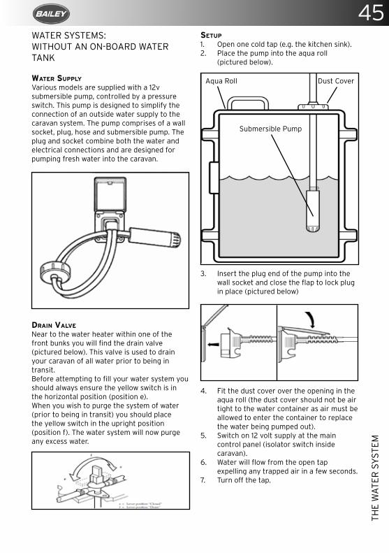
45
THE
WA
TER
SY
STEM
WATER SYSTEMS: WITHOUT AN ON-BOARD WATER TANK
WATER SUPPLY
Various models are supplied with a 12v submersible pump, controlled by a pressure switch. This pump is designed to simplify the connection of an outside water supply to the caravan system. The pump comprises of a wall socket, plug, hose and submersible pump. The plug and socket combine both the water and electrical connections and are designed for pumping fresh water into the caravan.
DRAIN VALVE
Near to the water heater within one of the front bunks you will find the drain valve (pictured below). This valve is used to drain your caravan of all water prior to being in transit. Before attempting to fill your water system you should always ensure the yellow switch is in the horizontal position (position e). When you wish to purge the system of water (prior to being in transit) you should place the yellow switch in the upright position (position f). The water system will now purge any excess water.
SETUP
1. Open one cold tap (e.g. the kitchen sink).2. Place the pump into the aqua roll
(pictured below).
3. Insert the plug end of the pump into the wall socket and close the flap to lock plug in place (pictured below)
4. Fit the dust cover over the opening in the aqua roll (the dust cover should not be air tight to the water container as air must be allowed to enter the container to replace the water being pumped out).
5. Switch on 12 volt supply at the main control panel (isolator switch inside caravan).
6. Water will flow from the open tap expelling any trapped air in a few seconds.
7. Turn off the tap.
Dust CoverAqua Roll
Submersible Pump
46TH
E W
ATE
R S
YST
EM
REMOVING THE PUMP
• Switch off the 12v supply at the control panel (isolator switch inside caravan).
• Pull the plug from socket.• Shut the flap.
Do not run pump dry or use the pump in water temperatures above 40°C (100°F)
It is best practice to stand the pump vertically in the tank.
ROUTINE MAINTENANCE
The micro-switch or phosphor bronze contacts can be removed for inspection or replacement.
Ensure the hose adaptor O-ring and the socket in the housing are kept free from dirt.
Use only silicone or water-based lubricant on the inlet nipple O-rings on the socket.
Service the inlet socket annually.
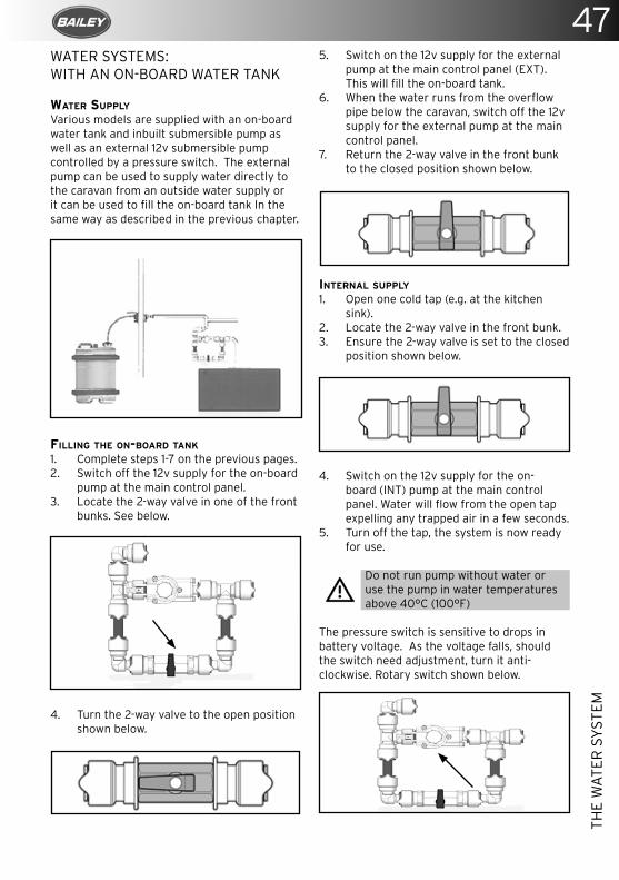
47
THE
WA
TER
SY
STEM
WATER SYSTEMS:WITH AN ON-BOARD WATER TANK
WATER SUPPLY
Various models are supplied with an on-board water tank and inbuilt submersible pump as well as an external 12v submersible pump controlled by a pressure switch. The external pump can be used to supply water directly to the caravan from an outside water supply or it can be used to fill the on-board tank In the same way as described in the previous chapter.
FILLING THE ON-BOARD TANK
1. Complete steps 1-7 on the previous pages.2. Switch off the 12v supply for the on-board
pump at the main control panel. 3. Locate the 2-way valve in one of the front
bunks. See below.
4. Turn the 2-way valve to the open position shown below.
5. Switch on the 12v supply for the external pump at the main control panel (EXT). This will fill the on-board tank.
6. When the water runs from the overflow pipe below the caravan, switch off the 12v supply for the external pump at the main control panel.
7. Return the 2-way valve in the front bunk to the closed position shown below.
INTERNAL SUPPLY
1. Open one cold tap (e.g. at the kitchen sink).
2. Locate the 2-way valve in the front bunk.3. Ensure the 2-way valve is set to the closed
position shown below.
4. Switch on the 12v supply for the on-board (INT) pump at the main control panel. Water will flow from the open tap expelling any trapped air in a few seconds.
5. Turn off the tap, the system is now ready for use.
Do not run pump without water or use the pump in water temperatures above 40°C (100°F)
The pressure switch is sensitive to drops in battery voltage. As the voltage falls, should the switch need adjustment, turn it anti-clockwise. Rotary switch shown below.
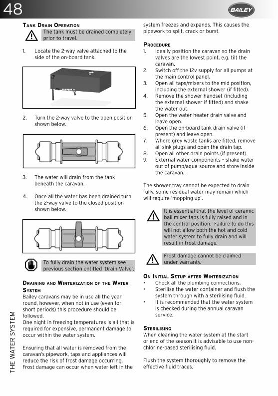
48TH
E W
ATE
R S
YST
EM
TANK DRAIN OPERATION
The tank must be drained completely prior to travel.
1. Locate the 2-way valve attached to the side of the on-board tank.
2. Turn the 2-way valve to the open position shown below.
3. The water will drain from the tank beneath the caravan.
4. Once all the water has been drained turn the 2-way valve to the closed position shown below.
To fully drain the water system see previous section entitled ‘Drain Valve’.
DRAINING AND WINTERIzATION OF THE WATER SYSTEM
Bailey caravans may be in use all the year round, however, when not in use (even for short periods) this procedure should be followed. One night in freezing temperatures is all that is required for expensive, permanent damage to occur within the water system.
Ensuring that all water is removed from the caravan’s pipework, taps and appliances will reduce the risk of frost damage occurring. Frost damage can occur when water left in the
system freezes and expands. This causes the pipework to split, crack or burst.
PROCEDURE
1. Ideally position the caravan so the drain valves are the lowest point, e.g. tilt the caravan.
2. Switch off the 12v supply for all pumps at the main control panel.
3. Open all taps/mixers to the mid position, including the external shower (if fitted).
4. Remove the shower handset (including the external shower if fitted) and shake the water out.
5. Open the water heater drain valve and leave open.
6. Open the on-board tank drain valve (if present) and leave open.
7. Where grey waste tanks are fitted, remove all sink plugs and open the drain tap.
8. Open all other drain points (if present).9. External water components – shake water
out of pump/aqua-source and store inside the caravan.
The shower tray cannot be expected to drain fully, some residual water may remain which will require ‘mopping up’.
It is essential that the level of ceramic ball mixer taps is fully raised and in the central position. Failure to do this will not allow both the hot and cold water system to fully drain and will result in frost damage.
Frost damage cannot be claimed under warranty.
ON INITIAL SETUP AFTER WINTERIzATION
• Check all the plumbing connections.• Sterilise the water container and flush the
system through with a sterilising fluid.• It is recommended that the water system
is checked during the annual caravan service.
STERILISING
When cleaning the water system at the start or end of the season it is advisable to use non-chlorine-based sterilising fluid.
Flush the system thoroughly to remove the effective fluid traces.
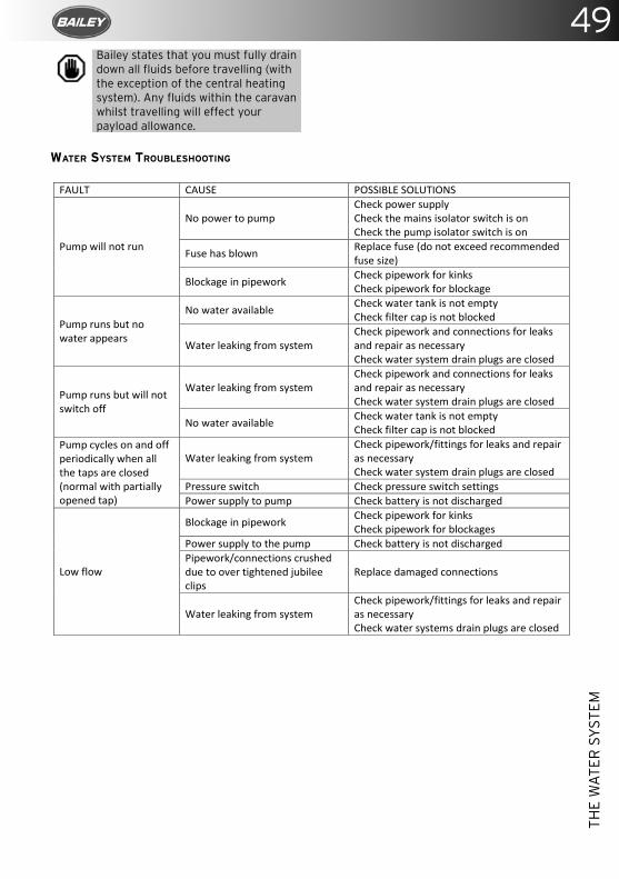
49
THE
WA
TER
SY
STEM
Bailey states that you must fully drain down all fluids before travelling (with the exception of the central heating system). Any fluids within the caravan whilst travelling will effect your payload allowance.
WATER SYSTEM TROUBLESHOOTING
Water System Trouble Shooting
FAULT CAUSE POSSIBLE SOLUTIONS
Pump will not run
No power to pump Check power supply Check the mains isolator switch is on Check the pump isolator switch is on
Fuse has blown Replace fuse (do not exceed recommended fuse size)
Blockage in pipework Check pipework for kinks Check pipework for blockage
Pump runs but no water appears
No water available Check water tank is not empty Check filter cap is not blocked
Water leaking from system Check pipework and connections for leaks and repair as necessary Check water system drain plugs are closed
Pump runs but will not switch off
Water leaking from system Check pipework and connections for leaks and repair as necessary Check water system drain plugs are closed
No water available Check water tank is not empty Check filter cap is not blocked
Pump cycles on and off periodically when all the taps are closed (normal with partially opened tap)
Water leaking from system Check pipework/fittings for leaks and repair as necessary Check water system drain plugs are closed
Pressure switch Check pressure switch settings Power supply to pump Check battery is not discharged
Low flow
Blockage in pipework Check pipework for kinks Check pipework for blockages
Power supply to the pump Check battery is not discharged Pipework/connections crushed due to over tightened jubilee clips
Replace damaged connections
Water leaking from system Check pipework/fittings for leaks and repair as necessary Check water systems drain plugs are closed
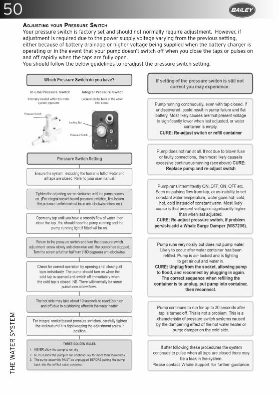
50TH
E W
ATE
R S
YST
EM
ADJUSTING YOUR PRESSURE SWITCH
Your pressure switch is factory set and should not normally require adjustment. However, if adjustment is required due to the power supply voltage varying from the previous setting, either because of battery drainage or higher voltage being supplied when the battery charger is operating or in the event that your pump doesn’t switch off when you close the taps or pulses on and off rapidly when the taps are fully open.You should follow the below guidelines to re-adjust the pressure switch setting.
Proudly powering your Bailey Caravan shower experiencewww.ecocamel.com
Whale Support Call today for advice on water
and heating systems
Taps and Showers
Space Heating
Plumbing
WaterPumps
Control
Water Heating
Phoneline available 7 days a
week
Market Leaders in innovative water and heating system technology
Tel: 0845 217 2933E-mail: [email protected]
www.whalepumps.com
Proud to manufacture in the UK
NEW
Facebook “f ” Logo CMYK / .eps Facebook “f ” Logo CMYK / .eps
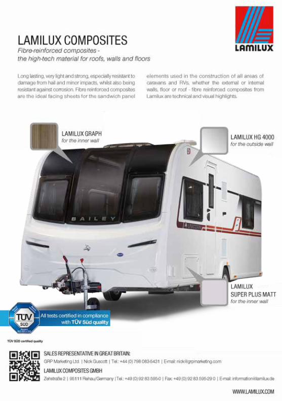
52
Mor
land
pro
udly
supp
lies B
aile
yIn
terio
r Pan
els,
Profi
les &
Flo
orin
g
Mor
land
, Uni
t 2,
Butti
ngto
n Cr
oss E
nter
prise
Par
k,W
elsh
pool
, Pow
ys, S
Y21
8SL
ww
w.m
orla
nd-u
k.co
mTe
l: +4
4 (0
)193
8 55
1 98
0
Bai
ley
A5
June
201
7.in
dd
112
/06/
2017
16
:46:
56

Mor
land
pro
udly
supp
lies B
aile
yIn
terio
r Pan
els,
Profi
les &
Flo
orin
g
Mor
land
, Uni
t 2,
Butti
ngto
n Cr
oss E
nter
prise
Par
k,W
elsh
pool
, Pow
ys, S
Y21
8SL
ww
w.m
orla
nd-u
k.co
mTe
l: +4
4 (0
)193
8 55
1 98
0
Bai
ley
A5
June
201
7.in
dd
112
/06/
2017
16
:46:
56
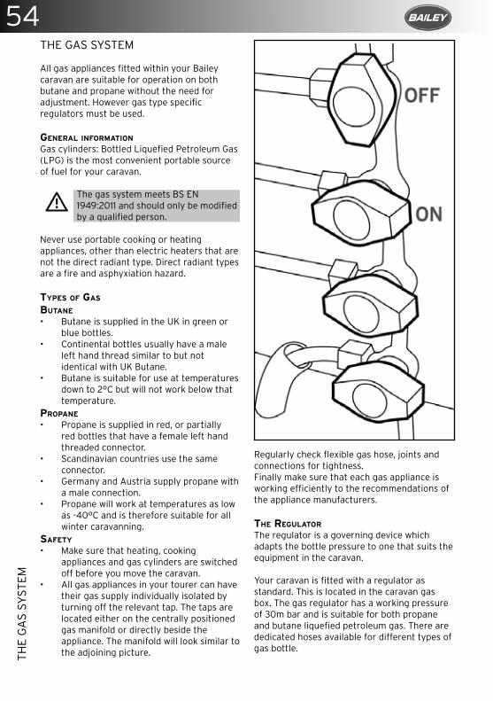
54TH
E G
AS
SYST
EM
THE GAS SYSTEM
All gas appliances fitted within your Bailey caravan are suitable for operation on both butane and propane without the need for adjustment. However gas type specific regulators must be used.
GENERAL INFORMATION
Gas cylinders: Bottled Liquefied Petroleum Gas (LPG) is the most convenient portable source of fuel for your caravan.
The gas system meets BS EN 1949:2011 and should only be modified by a qualified person.
Never use portable cooking or heating appliances, other than electric heaters that are not the direct radiant type. Direct radiant types are a fire and asphyxiation hazard.
TYPES OF GAS
BUTANE
• Butane is supplied in the UK in green or blue bottles.
• Continental bottles usually have a male left hand thread similar to but not identical with UK Butane.
• Butane is suitable for use at temperatures down to 2°C but will not work below that temperature.
PROPANE
• Propane is supplied in red, or partially red bottles that have a female left hand threaded connector.
• Scandinavian countries use the same connector.
• Germany and Austria supply propane with a male connection.
• Propane will work at temperatures as low as -40°C and is therefore suitable for all winter caravanning.
SAFETY
• Make sure that heating, cooking appliances and gas cylinders are switched off before you move the caravan.
• All gas appliances in your tourer can have their gas supply individually isolated by turning off the relevant tap. The taps are located either on the centrally positioned gas manifold or directly beside the appliance. The manifold will look similar to the adjoining picture.
Regularly check flexible gas hose, joints and connections for tightness.Finally make sure that each gas appliance is working efficiently to the recommendations of the appliance manufacturers.
THE REGULATOR
The regulator is a governing device which adapts the bottle pressure to one that suits the equipment in the caravan.
Your caravan is fitted with a regulator as standard. This is located in the caravan gas box. The gas regulator has a working pressure of 30m bar and is suitable for both propane and butane liquefied petroleum gas. There are dedicated hoses available for different types of gas bottle.
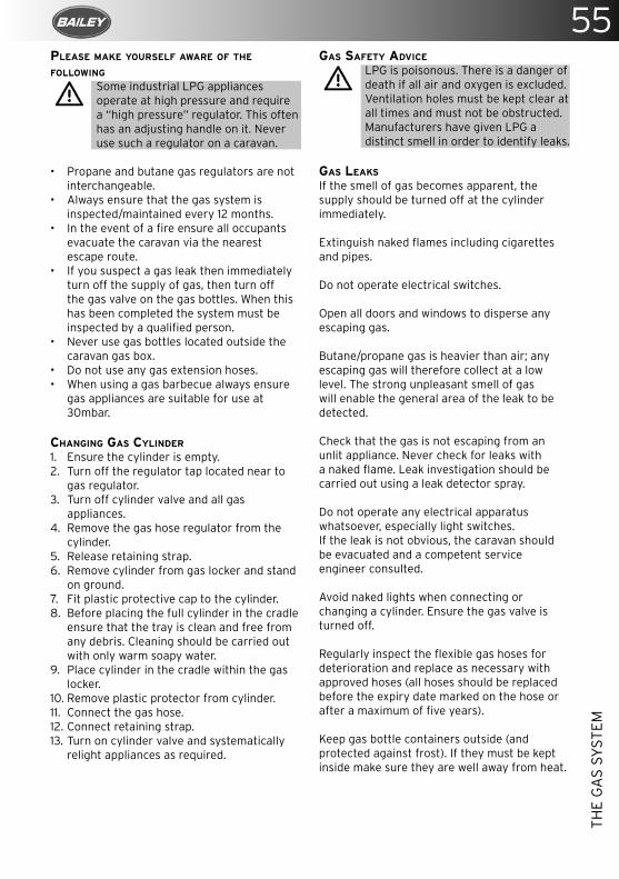
55
THE
GA
S SY
STEM
PLEASE MAKE YOURSELF AWARE OF THE FOLLOWING
Some industrial LPG appliances operate at high pressure and require a “high pressure” regulator. This often has an adjusting handle on it. Never use such a regulator on a caravan.
• Propane and butane gas regulators are not interchangeable.
• Always ensure that the gas system is inspected/maintained every 12 months.
• In the event of a fire ensure all occupants evacuate the caravan via the nearest escape route.
• If you suspect a gas leak then immediately turn off the supply of gas, then turn off the gas valve on the gas bottles. When this has been completed the system must be inspected by a qualified person.
• Never use gas bottles located outside the caravan gas box.
• Do not use any gas extension hoses.• When using a gas barbecue always ensure
gas appliances are suitable for use at 30mbar.
CHANGING GAS CYLINDER
1. Ensure the cylinder is empty.2. Turn off the regulator tap located near to
gas regulator.3. Turn off cylinder valve and all gas
appliances.4. Remove the gas hose regulator from the
cylinder.5. Release retaining strap.6. Remove cylinder from gas locker and stand
on ground.7. Fit plastic protective cap to the cylinder.8. Before placing the full cylinder in the cradle
ensure that the tray is clean and free from any debris. Cleaning should be carried out with only warm soapy water.
9. Place cylinder in the cradle within the gas locker.
10. Remove plastic protector from cylinder.11. Connect the gas hose.12. Connect retaining strap.13. Turn on cylinder valve and systematically
relight appliances as required.
GAS SAFETY ADVICE
LPG is poisonous. There is a danger of death if all air and oxygen is excluded. Ventilation holes must be kept clear at all times and must not be obstructed. Manufacturers have given LPG a distinct smell in order to identify leaks.
GAS LEAKS
If the smell of gas becomes apparent, the supply should be turned off at the cylinder immediately.
Extinguish naked flames including cigarettes and pipes.
Do not operate electrical switches.
Open all doors and windows to disperse any escaping gas.
Butane/propane gas is heavier than air; any escaping gas will therefore collect at a low level. The strong unpleasant smell of gas will enable the general area of the leak to be detected.
Check that the gas is not escaping from an unlit appliance. Never check for leaks with a naked flame. Leak investigation should be carried out using a leak detector spray.
Do not operate any electrical apparatus whatsoever, especially light switches.If the leak is not obvious, the caravan should be evacuated and a competent service engineer consulted.
Avoid naked lights when connecting or changing a cylinder. Ensure the gas valve is turned off.
Regularly inspect the flexible gas hoses for deterioration and replace as necessary with approved hoses (all hoses should be replaced before the expiry date marked on the hose or after a maximum of five years).
Keep gas bottle containers outside (and protected against frost). If they must be kept inside make sure they are well away from heat.
56TH
E G
AS
SYST
EM
VENTILATION
All ventilation complies with EN 721. Vents should not be obstructed in any manner as this could lead to insufficient ventilation. In this case the atmosphere becomes depleted of oxygen which leads to the formation of the highly poisonous gas Carbon Monoxide. Carbon Monoxide is odourless, colourless and tasteless and could rapidly cause unconsciousness leading to death with little or no warning prior.
Under no circumstances should the caravan’s ventilation be blocked or obstructed in any way.
High level ventilation is via the roof lights. Low level ventilation is via the vents in the floor in the caravan living area. With multi-berth layouts the rear sleeping compartments have their own low level ventilation. Please consult your caravan retailer for its location.
The mesh screens fitted should be kept free of obstructions by dust, leaves, insects etc. Inspect regularly and use a brush and soapy water as necessary. It may be necessary to remove the weather shield located on the underside of the floor of the caravan to gain access for cleaning.
All flue installations should be inspected once a year, throughout their life, for corrosion. Flues should be replaced if any sign of degradation is found. Ensure that the replacement is of an approved type. Check that the external seal is seating correctly and the locknut is fully tightened.
Do not make any additional openings in the floor.
Appliances such as cookers with naked flames should never be used for room heating.
No appliance shall be used inside when being connected to the external BBQ socket.
GAS BBQ POINT
The external gas BBQ point should never be used as a gas inlet it should only ever be used as a connection outlet.
Please be aware that contaminated gas will cause regulators to become damaged and fail. Any such failure caused by contaminated gas will not be covered by your warranty.
57
THE
ELEC
TRIC
AL
SYST
EM
THE 230v ELECTRICAL SYSTEM
As in the home, care must be exercised when using mains electricity.
UPON ARRIVAL AT CARAVAN SITE
When connecting the caravan installation to the mains supply:
When connecting caravan to the mains bollard, ALWAYS connect to the caravan first and then to the site bollard.
1. Check the mains supply is suitable for your installation and appliances.
2. Check that your installations will be properly earthed.
3. Never accept a supply from a socket outlet or plug having only two pins, or from a lighting outlet.
4. Check that any residual current device (RCD) or earth leakage circuit breaker in the mains supply to the caravan has been tested within the last month. After connection to site supply, test again.
5. Make sure that the switch at the site supply point is off.
6. Make sure that the caravan RCD unit is switched off.
7. Remove any cover from the electricity inlet provided on the caravan, and insert the connector of the supply cable.
8. Remove any cover from the socket outlet provided at the site supply point, and connect the plug at the other end of the supply cable.
9. Switch on the mains switch at the site supply point.
10. Switch on the caravan RCD unit.
In cases of doubt, consult the site owner or their agent.
When disconnecting caravan from the mains bollard, ALWAYS disconnect from the site bollard.
UPON LEAVING THE CARAVAN SITE
1. Switch off the site supply.2. Switch off the caravan RCD unit.3. Disconnect the pitch lead.4. Replace the cover of the socket outlet at
the site supply point. It is dangerous to leave the supply socket or supply cable live.
If you encounter difficulty, consult an approved electrical installation contractor (which may be the local electricity board). It is dangerous to attempt modifications yourself.
Every 12 months, the caravan electrical installation should be inspected, tested and a report on its condition obtained as prescribed in the Regulations for Electrical Installations, published by the Institute of Electrical Engineers.
OVERSEAS CONNECTIONS
Connection to a mains voltage supply overseas requires particular attention.
• Care must be taken when connecting supplies abroad since the supplies can be reverse polarity.
• The significance of reverse polarity is that when equipment is switched may not be electrically isolated.
• The only certain way of making equipment safe is to unplug it.
• A means of checking the polarity of the mains supply when overseas is useful.
• There are several proprietary makes of equipment available for this purpose. If it can be achieved, it is preferable to connect live to live, and neutral to neutral to maintain full electrical protection.
• Check all caravan equipment is set up to accept the site supply before actually switching on.
MAINS UNIT (PDU)The mains unit replaces the conventional fuse box. The unit gives overload and earth leakage protection for the 230v electrical supply in your caravan.
FOR NORMAL OPERATION
• All switches on the unit need to be set to the ON position. The switches on the left of the unit are known as MCBs (miniature circuit breakers). These take the place of the conventional fuse and are more convenient.
• In the event of a fault the MCB trips/automatically moves to the OFF position.
• After elimination of the fault the MCB can be re-set by switching to the ON position.
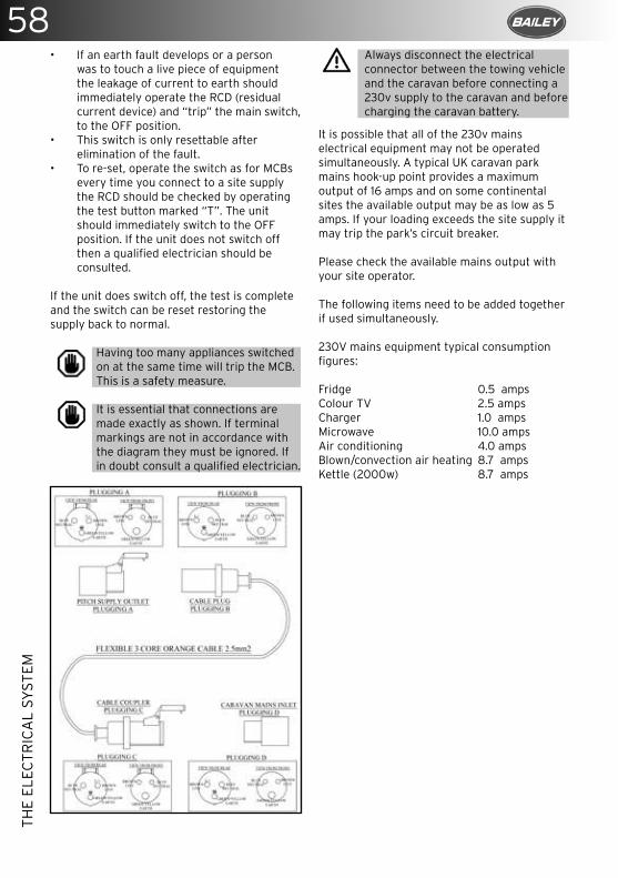
58TH
E EL
ECTR
ICA
L SY
STEM
• If an earth fault develops or a person was to touch a live piece of equipment the leakage of current to earth should immediately operate the RCD (residual current device) and “trip” the main switch, to the OFF position.
• This switch is only resettable after elimination of the fault.
• To re-set, operate the switch as for MCBs every time you connect to a site supply the RCD should be checked by operating the test button marked “T”. The unit should immediately switch to the OFF position. If the unit does not switch off then a qualified electrician should be consulted.
If the unit does switch off, the test is complete and the switch can be reset restoring the supply back to normal.
Having too many appliances switched on at the same time will trip the MCB. This is a safety measure.
It is essential that connections are made exactly as shown. If terminal markings are not in accordance with the diagram they must be ignored. If in doubt consult a qualified electrician.
Always disconnect the electrical connector between the towing vehicle and the caravan before connecting a 230v supply to the caravan and before charging the caravan battery.
It is possible that all of the 230v mains electrical equipment may not be operated simultaneously. A typical UK caravan park mains hook-up point provides a maximum output of 16 amps and on some continental sites the available output may be as low as 5 amps. If your loading exceeds the site supply it may trip the park’s circuit breaker.
Please check the available mains output with your site operator.
The following items need to be added together if used simultaneously.
230V mains equipment typical consumption figures:
Fridge 0.5 ampsColour TV 2.5 ampsCharger 1.0 amps Microwave 10.0 ampsAir conditioning 4.0 ampsBlown/convection air heating 8.7 ampsKettle (2000w) 8.7 amps
59THE 12v ELECTRICAL SYSTEM
Your caravan is fitted with a 12v charger as standard. This converts the 230v AC supply into 12v DC. It enables the 12v equipment in the caravan to function and also charges the caravan leisure battery when plugged into a site hook up. A fully charged caravan leisure battery should read 13.8 volts on the voltmeter mounted in the control panel. The charger is capable of charging leisure batteries and will not overcharge.
The 12v system is designed to operate with a leisure battery in circuit and should not be turned on without one connected. The 12v supply to the caravan services can be isolated via the 12v on/off switch on the control panel.
The battery must be placed in the tray provided in the battery storage compartment.
A battery of not less than 40-50 amps/hours capacity is recommended. Crocodile clips should never be used to connect the battery, and terminals should be shrouded. Always switch off all appliances and lamps before disconnecting the auxiliary battery.
• The battery should be secured to prevent movement when towing.
• Metal objects should not be stored in the battery box.
• Where a 12v extension is used between the tow-car and caravan, this should not exceed 5 metres in length- minimum cable size 2.5mm to minimise voltage drop.
• DIY modifications/additions to the wiring systems are not recommended. Always consult your retailer who will carry out such work.
• Do not continuously charge the battery when the caravan is not in use.
Negative connections should always be disconnected first and reconnected last.
Car type battery chargers are not suitable for charging a leisure battery and may damage it.
When not using the caravan always ensure that the fridge control is turned to the ‘off’ position. Failure to do this will result in a flat battery due to 12v power drain from the fridge circuit relays.
BATTERY BOX CONNECTIONS
Certain models are fitted with a 12v external solar panel connection point. This can be found on the side of your van.
Certain models also feature a connection for a free standing external satellite dish. This connection is located within the external 230v socket.
Any replacement of an auxiliary battery shall be of the same type and specification as originally fitted or as specified by the manufacturer.
THE
ELEC
TRIC
AL
SY
STEM

CO
MP
AC
T, L
IGH
TA
ND
SU
PE
R C
OO
L FJ 2
20
0
DO
MET
IC F
RES
HJE
T
RO
OFT
OP
AIR
CO
ND
ITIO
NE
RS
For m
ore
info
rmat
ion,
ple
ase
visi
t:
do
met
ic.c
om
• Fi
ve p
erfo
rman
ce le
vels
for v
ehic
les
from
5m
to o
ver 8
m lo
ng
• Ve
ry lo
w s
tart
ing
cur
rent
s - F
J 22
00
/ 2
700
/ 3
20
0 w
ith S
o� S
tart
• A
ir d
iff us
er w
ith tw
o ad
just
able
air
fl ow
s
• LE
D li
ght
ing
, rem
ote
cont
rol
2018
BE
ST
EM
AR
KE
N
1. P
LATZ
Dom
etic
Kl
imaa
nlag
en
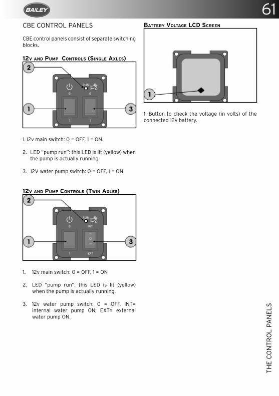
61
THE
CO
NTR
OL
PAN
ELS
CBE CONTROL PANELS
CBE control panels consist of separate switching blocks.
12V AND PUMP CONTROLS (SINGLE AXLES)
1. 12v main switch: 0 = OFF, 1 = ON.
2. LED “pump run”: this LED is lit (yellow) when the pump is actually running.
3. 12V water pump switch: 0 = OFF, 1 = ON.
12V AND PUMP CONTROLS (TWIN AXLES)
1. 12v main switch: 0 = OFF, 1 = ON
2. LED “pump run”: this LED is lit (yellow) when the pump is actually running.
3. 12v water pump switch: 0 = OFF, INT= internal water pump ON; EXT= external water pump ON.
BATTERY VOLTAGE LCD SCREEN
1. Button to check the voltage (in volts) of the connected 12v battery.
THE
CO
NTR
OL
PAN
ELS
CLE
AN
ER
, LIG
HTE
R A
ND
E
ASI
ER
TH
AN
A L
IQU
ID
DO
ME
TIC
PO
WE
RC
AR
E T
AB
S FO
R Y
OU
R T
OIL
ET
WA
STE
TA
NK
No
spill
s, p
re-m
easu
red
dos
age,
tab
s in
sol
uble
fi lm
s, e
asy
stor
age,
16
tab
s p
er tu
b, fo
r all
por
tab
le &
cas
sett
e to
ilets
.
Ove
r 5
tim
es li
gh
ter
than
a s
tand
ard
2 li
tre
bot
tle o
f blu
e liq
uid
fo
r the
sam
e am
ount
of d
oses
.
For m
ore
info
rmat
ion,
ple
ase
visi
t:d
om
etic
.co
m
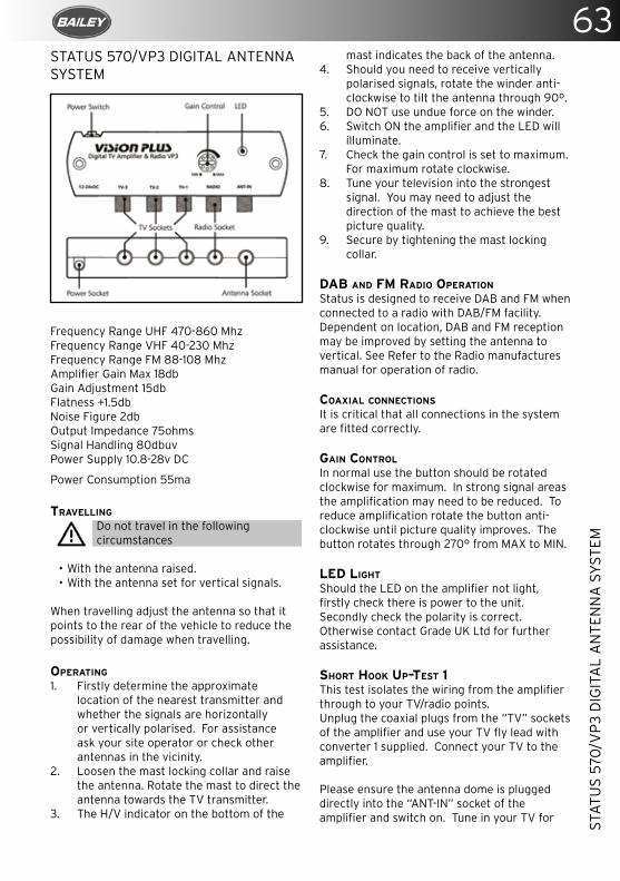
63
STA
TUS
570/
VP
3 D
IGIT
AL
AN
TEN
NA
SY
STEM
STATUS 570/VP3 DIGITAL ANTENNA SYSTEM
Frequency Range UHF 470-860 MhzFrequency Range VHF 40-230 MhzFrequency Range FM 88-108 MhzAmplifier Gain Max 18dbGain Adjustment 15dbFlatness +1.5dbNoise Figure 2dbOutput Impedance 75ohmsSignal Handling 80dbuvPower Supply 10.8-28v DC
Power Consumption 55ma
TRAVELLING
Do not travel in the following circumstances
• With the antenna raised.• With the antenna set for vertical signals.
When travelling adjust the antenna so that it points to the rear of the vehicle to reduce the possibility of damage when travelling.
OPERATING
1. Firstly determine the approximate location of the nearest transmitter and whether the signals are horizontally or vertically polarised. For assistance ask your site operator or check other antennas in the vicinity.
2. Loosen the mast locking collar and raise the antenna. Rotate the mast to direct the antenna towards the TV transmitter.
3. The H/V indicator on the bottom of the
mast indicates the back of the antenna.4. Should you need to receive vertically
polarised signals, rotate the winder anti-clockwise to tilt the antenna through 90º.
5. DO NOT use undue force on the winder.6. Switch ON the amplifier and the LED will
illuminate.7. Check the gain control is set to maximum.
For maximum rotate clockwise.8. Tune your television into the strongest
signal. You may need to adjust the direction of the mast to achieve the best picture quality.
9. Secure by tightening the mast locking collar.
DAB AND FM RADIO OPERATION
Status is designed to receive DAB and FM when connected to a radio with DAB/FM facility. Dependent on location, DAB and FM reception may be improved by setting the antenna to vertical. See Refer to the Radio manufactures manual for operation of radio.
COAXIAL CONNECTIONS
It is critical that all connections in the system are fitted correctly.
GAIN CONTROL
In normal use the button should be rotated clockwise for maximum. In strong signal areas the amplification may need to be reduced. To reduce amplification rotate the button anti-clockwise until picture quality improves. The button rotates through 270° from MAX to MIN.
LED LIGHT
Should the LED on the amplifier not light, firstly check there is power to the unit. Secondly check the polarity is correct. Otherwise contact Grade UK Ltd for further assistance.
SHORT HOOK UP–TEST 1This test isolates the wiring from the amplifier through to your TV/radio points.Unplug the coaxial plugs from the “TV” sockets of the amplifier and use your TV fly lead with converter 1 supplied. Connect your TV to the amplifier.
Please ensure the antenna dome is plugged directly into the “ANT-IN” socket of the amplifier and switch on. Tune in your TV for
64ST
ATU
S 57
0/V
P3
DIG
ITA
L A
NTE
NN
A S
YST
EM
the strongest signal. If the picture quality improves the fault lies with the wiring of the system between the amplifier and TV outlet socket.
SHORT HOOK UP: TEST 2This test isolates the amplifier by connecting your TV direct to the antenna.Unplug the antenna from the amplifier and connect converter 2 supplied to the plug on the cable end. Using your fly lead, connect the antenna directly to your TV. Tune in your TV for the strongest signal.If the picture quality improves, the fault lies with the amplifier.
ANTENNA DOME COAXIAL CABLE
Check the routing of the coaxial cable from the antenna dome to the amplifier. Check to ensure there are no kinks or trapped cable or if there are loops of surplus cable which could affect performance.
Should you still be experiencing difficulties and require assistance, please do not hesitate to contact Vision Plus for further assistance on +44 (0) 115 986 7151 or Visit www.visionplus.co.uk
It is the responsibility of the caravan owner to make sure that the directional aerial is fully retracted before the caravan is moved. Any damage as a result of neglect, i.e. not retracting the aerial, crash damage, vandalism or incorrect operation will NOT be covered by the manufacturer’s warranty.
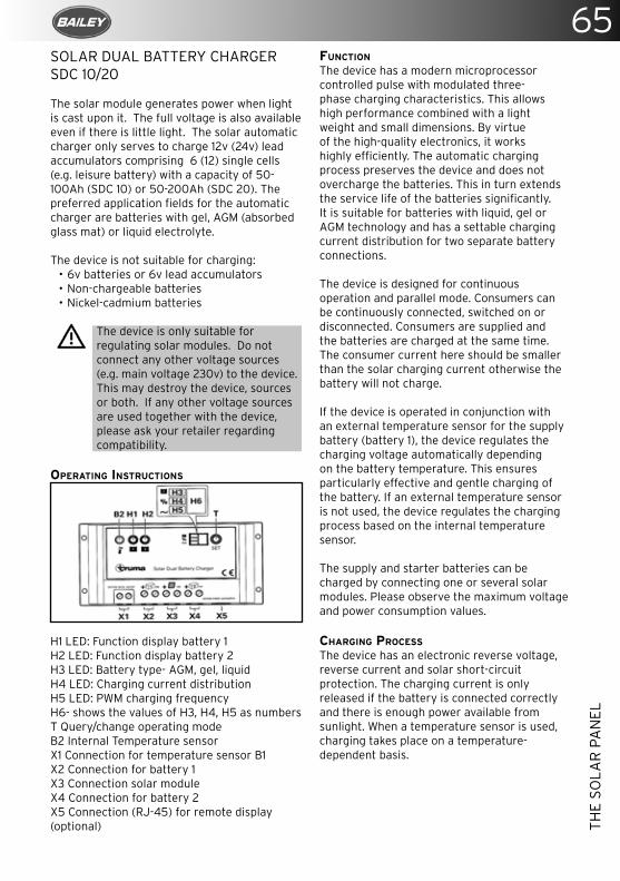
65
THE
SOLA
R P
AN
EL
SOLAR DUAL BATTERY CHARGER SDC 10/20
The solar module generates power when light is cast upon it. The full voltage is also available even if there is little light. The solar automatic charger only serves to charge 12v (24v) lead accumulators comprising 6 (12) single cells (e.g. leisure battery) with a capacity of 50-100Ah (SDC 10) or 50-200Ah (SDC 20). The preferred application fields for the automatic charger are batteries with gel, AGM (absorbed glass mat) or liquid electrolyte. The device is not suitable for charging:
• 6v batteries or 6v lead accumulators• Non-chargeable batteries• Nickel-cadmium batteries
The device is only suitable for regulating solar modules. Do not connect any other voltage sources (e.g. main voltage 230v) to the device. This may destroy the device, sources or both. If any other voltage sources are used together with the device, please ask your retailer regarding compatibility.
OPERATING INSTRUCTIONS
H1 LED: Function display battery 1H2 LED: Function display battery 2H3 LED: Battery type- AGM, gel, liquidH4 LED: Charging current distributionH5 LED: PWM charging frequencyH6- shows the values of H3, H4, H5 as numbersT Query/change operating modeB2 Internal Temperature sensorX1 Connection for temperature sensor B1X2 Connection for battery 1 X3 Connection solar moduleX4 Connection for battery 2X5 Connection (RJ-45) for remote display (optional)
FUNCTION The device has a modern microprocessor controlled pulse with modulated three-phase charging characteristics. This allows high performance combined with a light weight and small dimensions. By virtue of the high-quality electronics, it works highly efficiently. The automatic charging process preserves the device and does not overcharge the batteries. This in turn extends the service life of the batteries significantly. It is suitable for batteries with liquid, gel or AGM technology and has a settable charging current distribution for two separate battery connections. The device is designed for continuous operation and parallel mode. Consumers can be continuously connected, switched on or disconnected. Consumers are supplied and the batteries are charged at the same time. The consumer current here should be smaller than the solar charging current otherwise the battery will not charge.
If the device is operated in conjunction with an external temperature sensor for the supply battery (battery 1), the device regulates the charging voltage automatically depending on the battery temperature. This ensures particularly effective and gentle charging of the battery. If an external temperature sensor is not used, the device regulates the charging process based on the internal temperature sensor.
The supply and starter batteries can be charged by connecting one or several solar modules. Please observe the maximum voltage and power consumption values.
CHARGING PROCESS The device has an electronic reverse voltage, reverse current and solar short-circuit protection. The charging current is only released if the battery is connected correctly and there is enough power available from sunlight. When a temperature sensor is used, charging takes place on a temperature-dependent basis.
66TH
E SO
LAR
PA
NEL
BULK PHASE Charging with maximum available solar charging current until the charging end voltage is reached.
ABSORPTION PHASE The charging current is kept for a period of 2 hours. At the end of this period, it changes to the float phase.
FLOAT PHASE The charging voltage is set to 13.8v. The charging current drops to the value necessary to compensate the self-consumption of the battery. Power is still supplied to the consumers. If the consumed current exceeds the available solar charging current, the charging process can no longer be maintained. If the battery voltage drops below 13.3v, the device automatically switches to the bulk phase if there is adequate solar charging current.
EQUALISATION CHARGING PHASE (ONLY FOR AGM AND LIQUID ELECTROLYTE BATTERY TYPE) The equalisation charging phase serves to compensate the cell voltages and can reduce any sulphation. If the voltage of the battery drops below 11.1v, it is assumed that the battery has deep-discharged. The device is switched to the equalisation charging phase for 2 hours. At the end of this period, it changes automatically to the float phase.
Deep-discharged batteries can be permanently damaged. Equalisation charging cannot repair this. Use a Truma battery monitor to prevent deep-discharging.
PARALLEL MODE If load current is consumed while the battery is being charged, it is served from the available solar charging current. If the consumed current exceeds the available solar charging current, the device cannot charge the battery. The device starts charging automatically once an adequate amount of solar charging current is available again.
SETTINGS
The display H6 shows different system settings. Press the key (T) to switch between LED H3, H4, H5 and H6. If the key is pressed again, the system starts at LED H3 again.
BATTERY TYPE The battery type can only be set for battery 1; battery 2 is assumed to be the same battery type.
QUERY • Press (T) until LED H3 illuminates; the saved
value is shown in display H6.
DISPLAY H6 BATTERY TYPE
1 Gel (pre-setting)
2 AGM
3 Liquid (liquid electrolyte)
Change • Press key (T) for 5 seconds until the display
H6 flashes. • Press the key (T) to set the required value. • If the key is not pressed for 5 seconds, the
displayed value will be saved and flashing stops.
CHARGING CURRENT DISTRIBUTION The charging current distribution between battery 1 and battery 2 can be set. The following distributions can be selected.
Query • Press (T) until LED H4 illuminates; the
saved value is shown in display H6.
BATTERY 1 BATTERY 2
0 0% 100%
1 10% 90%
2 20% 80%
3 30% 70%
4 40% 60%
5 50% (pre-setting) 50%
6 60% 40%
7 70% 30%
8 80% 20%
9 90% 10%
Change • Press key (T) for 5 seconds until the display
H6 flashes. • Press the key (T) to set the required value. • If the key is not pressed for 5 seconds, the
displayed value will be saved and flashing stops.
67
THE
SOLA
R P
AN
EL
During the normal charging process, the device divides the charging current between battery 1 and battery 2 as set. Once battery 1 is fully charged, all the charging current is fed to battery 2, regardless of the set value. If the voltage of battery 1 drops, the charging process starts again. If only battery 1 is connected, the entire charging current is supplied to this battery regardless of the set value.
PWM CHARGING FREQUENCY The pulse frequency of the device can be set here. This may be changed to reduce possible interferences.
QUERY • Press (T) until LED H5 illuminates; the
saved value is shown in display H6.
DISPLAY H6 PWM CHARGING FREQUENCY
0 25Hz (pre-setting)
1 50Hz
2 100Hz
Change• Press key (T) for 5 seconds until the display
H6 flashes. • Press the key (T) to set the required value. • If the key is not pressed for 5 seconds, the
displayed value will be saved and flashing stops.
FUNCTION DISPLAY / TROUBLESHOOTING LED H2 shows the status of battery 1.Battery 2 double the values of the 12v- to work out the 24v values
DISPLAY CAUSE/RECTIFICATION
LED flashes Check connections from the device to the battery and solar module, ensure that they are connected to the right terminals. Test the fuse, solar module and battery
LED flashes in longer intervals
Battery is fully charged
LED shines The battery is being charged
LED flashes in short intervals
The battery is not being charged. If necessary, replace faulty battery
LED does not shine
Battery not connected or over-voltage
If this does not solve the problem, please contact the Truma Service.
REPAIRS
Do not repair or modify the solar panel. Please contact your retailer or the Truma Service.
CAUTIONS
• Liquid electrolyte batteries can create explosive gases, so ensure there is adequate ventilation.
• Check the liquid level at regular intervals. Overcharging can damage your battery; check the technical data for your battery.
• Equalisation charging increases the charging voltage; this may damage the consumer. Ensure that all consumers are designed for these voltages.
68H
EATI
NG
SY
STEM
S
HEATING SYSTEMS
ALDE HEATING SYSTEMS
Always replace the heat transfer fluid (HTF) in accordance with the antifreeze product’s lifespan. If in any doubt, replace the HTF after 2 years.
The corrosion inhibitors found in ethylene glycol antifreeze may not be cross-compatible. When topping up or replacing the HTF ensure the new antifreeze is compatible with the current antifreeze product. Read the product label or contact the product manufacturer for details.
OPERATING INSTRUCTIONS 3020 Compact High Efficiency Boiler
These instructions are approved for the Alde 3020 Compact HE boiler fitted in caravans in accordance with CE 0402 no. SC0653-13 and have the E5 mark for installation in vehicles in accordance with ECE R122, no. 00 001 and R10, no. 04 166, for use in central heating and hot water systems.
The boiler is not intended for use by persons (including children) with reduced physical sensory or mental capabilities, or lack of experience and/or knowledge, unless they have been given instruction or are supervised.The term “specified use” also covers observance of the operating and installation instructions.
The Alde 3020 Compact HE boiler must be installed or repaired by a competent person in accordance with current local regulations. In the unlikely event that your boiler develops a fault, switch off the boiler and contact Alde, or your dealer or installer.
Operating and installation instructions for the Alde control panel are supplied separately.
BOILER DESIGN
The boiler’s internal heat exchanger consists of three concentric cylinders: the combustion chamber, the central heating cylinder and the hot water cylinder.The combustion chamber is made from aluminium and is divided into two halves by a
baffle plate, with the burner head located in the top half and the flue gases venting through the bottom half.
The combustion assembly is fixed to the end of the internal heat exchanger. It consists of the burner, combustion fan, gas valve, air intake, exhaust ducts and gas line.
Two electric heating elements are sealed inside the central heating cylinder, one for 1kW, one for 2kW.
DESCRIPTION OF FUNCTIONS:GAS HEATING
When gas heating is set to “On” the combustion fan starts to revolve. Once the correct speed is achieved (in rpm), a signal is sent to the PCB (printed circuit board) for the burner to be lit. The gas valve opens passing gas and the ignition module on the PCB generates sparks at the electrode on the burner head.
When the burner ignites a flame supervision device (FSD) signals the ignition module to cease sparking. The burner fires until the boiler or room thermostat reach the set-point.
Should the burner flame go out unexpectedly, the FSD detects this and attempts to reignite (for about 10 seconds), before shutting down and raising a fault code.
Listen carefully to the ignition sequence of the boiler. You should hear the whir of the combustion fan, the clunk of the gas valve then the tick-tick of the ignition module.
ELECTRIC HEATING
When electric heating is set to 1, 2 or 3kW relays on the PCB trip, feeding the 230 v supply to the electric heating elements. These are controlled by the same programme as the gas heating.
DOMESTIC HOT WATER
The combi-type boiler automatically produces hot water. Heat is emitted from the central heating cylinder into the hot water cylinder. If the hot water cylinder is empty the air is heated but no damage will occur.In a good summer lower the desired
69
HEA
TIN
G S
YST
EMS
temperature on the control panel to around 10°C. The central heating will not circulate (unless the temperature drops to 10°C), but you will still have hot water.
• The boiler must not be switched on if there is no heat transfer fluid (HTF) in the system.
• Always drain down the freshwater system if there is risk of frost.
• You may continue to use the boiler with no freshwater in the system, as required; no damage will occur.
• Always replace the HTF in accordance with the antifreeze product’s lifespan.
• If in any doubt, replace the HTF after 2 years.
• Only sterilise the freshwater system with a product suitable for stainless steel.
• Do not place stowage in the boiler compartment.
• Do not position awnings, tents or other enclosures around the flue terminal.
• Do not obstruct the flue. Be careful not to flood the flue when washing the vehicle.
• The gas heating must not be used when refuelling the vehicle at the service station or related facility.
Being a combi-type boiler, the Alde 3020 Compact HE has an integrated stainless steel hot water cylinder that holds approximately 8.4 litres of freshwater.The boiler can produce around 12 litres of 40°C warm water per 30 mins (at a cold water temperature of 10°C). If only the electric heating is used, this capacity is slightly reduced.The hot water should not be used for drinking or cooking.
Always flush out the hot water cylinder before use, especially when it has stood empty for some time.
Any steriliser products should be suitable for use with stainless steel.
Avoid steriliser products containing sodium hyperchlorite as these will cause severe corrosion damage to the hot water cylinder which is not covered under warranty. Read the product label or contact the product manufacturer for details.When the hot water cylinder is in continuous
use, it should be drained and refilled once a month. This recreates the air cushion in the hot water cylinder that absorbs pressure surges.
If continuously using the hot water cylinder in a hard water area, fit an in-line scale inhibitor to minimise the effects of limescale.
The target hot water temperature is greater than 50°C in normal operation to prevent the growth of Legionella. The hot water will be heated to the maximum achievable temperature at the time. This allows the hot water to achieve disinfection temperatures and increases warm water performance.If scalding hot water temperatures are a concern thermostatic mixing valves (TMVs) can be fitted.
Alde recommends fitting the 3102-002 high temperature TMV.
Always drain down and completely empty the hot water cylinder when there is risk of frost, unless the vehicle is explicitly stated to be self-winterizing by the vehicle manufacturer.
Failure to drain the hot water cylinder when there is a risk of frost may result in frost damage, which is not covered under warranty.
DRAINING FRESHWATER
1. Switch off the water pump.2. Open all water taps, showers, etc.3. Open the safety/drain valve by lifting the
yellow tab (Fig.1 [M]) or by turning the blue knob (Fig 1.[K]) 90°.
The system will drain directly below the vehicle.
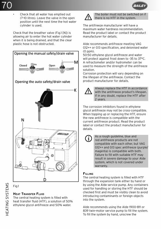
70H
EATI
NG
SY
STEM
S
• Check that all water has emptied out (7–10 litres). Leave the valve in the open position until the next time the hot water cylinder is used.
Check that the breather valve (Fig.1 [N]) is allowing air to enter the hot water cylinder when it is being drained, and that the clear plastic hose is not obstructed.
Fig.1
HEAT TRANSFER FLUID
The central heating system is filled with heat transfer fluid (HTF), a solution of 50% ethylene glycol antifreeze and 50% water.
The boiler must not be switched on if there is no HTF in the system.
The antifreeze manufacturer will have a maximum water hardness recommendation. Read the product label or contact the product manufacturer for details.
Alde recommends antifreeze meeting VAG G12++ or G13 specification, and deionised water (0 ppm).50:50 ethylene glycol antifreeze and water will protect against frost down to -35 to 37°C. A refractometer and/or hydrometer can be used to measure the strength of the antifreeze solution.Corrosion protection will vary depending on the lifespan of the antifreeze. Contact the product manufacturer for details.
Always replace the HTF in accordance with the antifreeze product’s lifespan. If in any doubt, replace the HTF after 2 years.
The corrosion inhibitors found in ethylene glycol antifreeze may not be cross-compatible. When topping up or replacing the HTF, ensure the new antifreeze is compatible with the current antifreeze product. Read the product label or contact the product manufacturer for details.
As a rough guideline, blue and red antifreeze products are not compatible with each other, but VAG G12++ and G13 spec antifreeze (purple/magenta) is compatible with both. Failure to fill with suitable HTF may result in severe damage to your Alde system, which is not covered under warranty.
FILLING
The central heating system is filled with HTF through the expansion tank either by hand or by using the Alde service pump. Any containers used for handling or storing the HTF should be checked first and must be visibly clean to avoid introducing contaminants or foreign objects into the system.
Alde recommends using the Alde 1900-811 or 839 twin-motor service pump to fill the system.To fill the system by hand, unscrew the
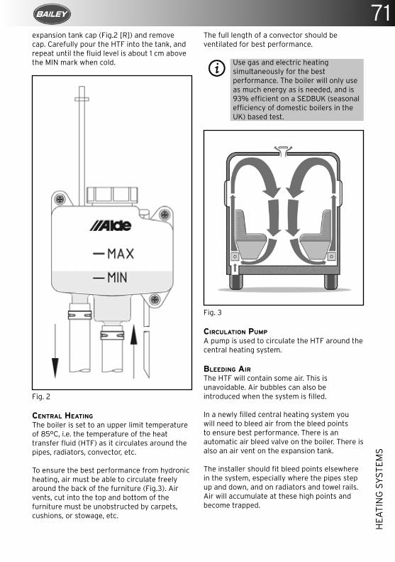
71
HEA
TIN
G S
YST
EMS
expansion tank cap (Fig.2 [R]) and remove cap. Carefully pour the HTF into the tank, and repeat until the fluid level is about 1 cm above the MIN mark when cold.
Fig. 2 CENTRAL HEATING
The boiler is set to an upper limit temperature of 85°C, i.e. the temperature of the heat transfer fluid (HTF) as it circulates around the pipes, radiators, convector, etc.
To ensure the best performance from hydronic heating, air must be able to circulate freely around the back of the furniture (Fig.3). Air vents, cut into the top and bottom of the furniture must be unobstructed by carpets, cushions, or stowage, etc.
The full length of a convector should be ventilated for best performance.
Use gas and electric heating simultaneously for the best performance. The boiler will only use as much energy as is needed, and is 93% efficient on a SEDBUK (seasonal efficiency of domestic boilers in the UK) based test.
Fig. 3 CIRCULATION PUMP
A pump is used to circulate the HTF around the central heating system.
BLEEDING AIR
The HTF will contain some air. This is unavoidable. Air bubbles can also be introduced when the system is filled.
In a newly filled central heating system you will need to bleed air from the bleed points to ensure best performance. There is an automatic air bleed valve on the boiler. There is also an air vent on the expansion tank.
The installer should fit bleed points elsewhere in the system, especially where the pipes step up and down, and on radiators and towel rails. Air will accumulate at these high points and become trapped.
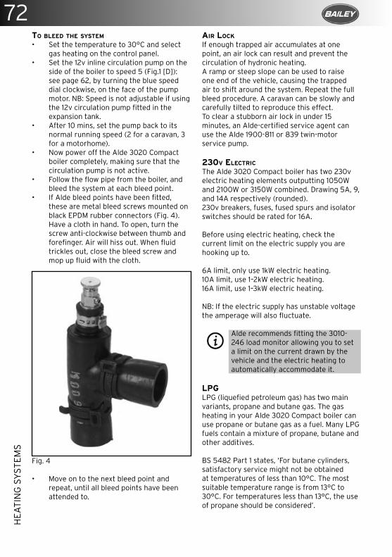
72H
EATI
NG
SY
STEM
S
TO BLEED THE SYSTEM
• Set the temperature to 30°C and select gas heating on the control panel.
• Set the 12v inline circulation pump on the side of the boiler to speed 5 (Fig.1 [D]): see page 62, by turning the blue speed dial clockwise, on the face of the pump motor. NB: Speed is not adjustable if using the 12v circulation pump fitted in the expansion tank.
• After 10 mins, set the pump back to its normal running speed (2 for a caravan, 3 for a motorhome).
• Now power off the Alde 3020 Compact boiler completely, making sure that the circulation pump is not active.
• Follow the flow pipe from the boiler, and bleed the system at each bleed point.
• If Alde bleed points have been fitted, these are metal bleed screws mounted on black EPDM rubber connectors (Fig. 4). Have a cloth in hand. To open, turn the screw anti-clockwise between thumb and forefinger. Air will hiss out. When fluid trickles out, close the bleed screw and mop up fluid with the cloth.
Fig. 4
• Move on to the next bleed point and repeat, until all bleed points have been attended to.
AIR LOCK
If enough trapped air accumulates at one point, an air lock can result and prevent the circulation of hydronic heating. A ramp or steep slope can be used to raise one end of the vehicle, causing the trapped air to shift around the system. Repeat the full bleed procedure. A caravan can be slowly and carefully tilted to reproduce this effect.To clear a stubborn air lock in under 15 minutes, an Alde-certified service agent can use the Alde 1900-811 or 839 twin-motor service pump.
230V ELECTRIC
The Alde 3020 Compact boiler has two 230v electric heating elements outputting 1050W and 2100W or 3150W combined. Drawing 5A, 9, and 14A respectively (rounded).230v breakers, fuses, fused spurs and isolator switches should be rated for 16A.
Before using electric heating, check the current limit on the electric supply you are hooking up to.
6A limit, only use 1kW electric heating.10A limit, use 1–2kW electric heating.16A limit, use 1–3kW electric heating.
NB: If the electric supply has unstable voltage the amperage will also fluctuate.
Alde recommends fitting the 3010-246 load monitor allowing you to set a limit on the current drawn by the vehicle and the electric heating to automatically accommodate it.
LPGLPG (liquefied petroleum gas) has two main variants, propane and butane gas. The gas heating in your Alde 3020 Compact boiler can use propane or butane gas as a fuel. Many LPG fuels contain a mixture of propane, butane and other additives.
BS 5482 Part 1 states, ‘For butane cylinders, satisfactory service might not be obtained at temperatures of less than 10°C. The most suitable temperature range is from 13°C to 30°C. For temperatures less than 13°C, the use of propane should be considered’.
73
HEA
TIN
G S
YST
EMS
For this reason, Alde recommends using propane gas for all year round gas heating.LPG cylinders contain both gas and liquid forms. When the cylinder is filled, high pressure transforms the gas into liquid. The liquid reverts to gas when the valve on the cylinder is opened.LPG is a flammable gas. It can be a fire and explosion hazard if stored or used incorrectly. Store cylinders vertically and securely, to prevent them from toppling.
Do not mount your LPG cylinder horizontally or use liquid phase gas cylinders. Liquid–gas explosion may result. Read the product label or contact product manufacturer for details.LPG is heavier than air. Should a gas leak occur, floor vents in a caravan or motorhome should allow the gas to escape from the vehicle. For this reason, always ensure floor vents are unobstructed.
The boiler compartment contains the gas connection, floor vents and the flue hoses. Do not place stowage in the boiler compartment.
In the event of a gas leak, or if you smell gas:• Extinguish all naked flames.• Open all doors and windows.• Close all gas valves, including the valve on
the cylinder.• Do not smoke.• Do not operate any electrical appliances
or switches.• Arrange for immediate inspection of the
gas system by a competent person in accordance with current local regulations.
LPG from the cylinder is reduced in pressure by a regulator, and is supplied to the boiler at low pressure (30mbar). Never use an unregulated high pressure supply.Where oil and dirt in the gas supply are a concern, gas filters should be fitted to prevent blockage of the boiler gas valve.NB: Gas heating must not be used while driving your vehicle unless a safety shut-off device is fitted to the gas system. Current local regulations must be adhered to.
FLUE
The burning of LPG produces CO2 (carbon dioxide), a non-toxic, asphyxiant gas.
Exhaust flue gas can cause possible burns and poisoning. Avoid inhaling exhaust flue gas.
Do not position awnings, tents or other enclosures around the flue terminal.
Air supply is essential for clean combustion. The air intake is located in the flue terminal. For best performance the flue terminal should be well vented. If you are intent on leaving the gas heating unused for a substantial period of time ensure the flue terminal is covered to prevent blockage of the flue.
Do not obstruct the flue. Be careful not to flood the flue when washing the vehicle.
The gas heating must not be used when refuelling the vehicle at the service station or related facility.
MAINTENANCE
There is no manufacturer’s service requirement for the boiler itself. The installation of the boiler should be inspected annually for gas safety.
LPG hoses should be regularly checked for signs of damage and should be replaced, at maximum, after 3 years of use.
Bleed air from the system when newly filled, when the vehicle has been standing unused for a period, and before departing on holiday.
The fluid level in the expansion tank should be about 1cm above the MIN mark when cool. The heat transfer fluid (HTF) should be topped up if below this level, to prevent a break in circulation. Only top up with compatible HTF.
Always replace the HTF in accordance with the antifreeze product’s lifespan. If in any doubt, replace the HTF after 2 years.
Failure to maintain the condition of HTF may result in frost and/or corrosion damage, and is not covered under warranty.
When the hot water cylinder is in continuous use, it should be drained and refilled each month. This recreates the air cushion in the cylinder that absorbs pressure surges.
74H
EATI
NG
SY
STEM
S
WINTER
When camping in the winter always ensure the flue terminal remains unobstructed by snow and ice. Extensions for roof flue terminals and condensate spouts for side flue terminals are available from Alde.
Check the strength of the HTF with a hydrometer and/or refractometer. It should measure 50% ethylene glycol antifreeze or -35 to 37°C.
The central heating can still be used with no freshwater in the system. The air in the hot water cylinder is heated but no damage will occur.
Always drain down and completely empty the hot water cylinder when there is risk of frost, unless the vehicle is explicitly stated to be self-winterizing by the vehicle manufacturer
If camping in temperatures below -10°C, consider carrying spare parts in the event of an emergency. Alde recommends a 12v circulation pump for the expansion tank (with cabling) a PCB, and 4–5 litres of ready to use antifreeze. These spare parts should be kept well insulated and in the warmest part of the vehicle, for example, in the wardrobe near to the expansion tank pipes.
If storing the vehicle for winter ensure the flue terminal is covered to prevent blockage of the flue.
If using the light duty 12v circulation pump in the expansion tank do not leave the central heating on over winter even with a low desired temperature set.
Air the vehicle over the winter without wearing out the light duty pump. Use the programmable Alde control panel to automatically heat the vehicle for 24 hours, once a week.
Only use potable fresh water. Grey water, desalinated water, or water otherwise unfit to drink is not suitable for use as domestic hot water.
TROUBLESHOOTING
The Alde control panel will display messages regarding any error that may have occured.
The system is completely dead/the control panel is blank• Check the 20mm T3.15 amp glass fuse in
the boiler. This is located under the lid of the black plastic service hatch in a green plastic fuse holder.
• Check the 12v supply to the boiler, it should be above 12v.
• Check the 12v cable is plugged into the boiler. Check the cable is plugged into the Alde control panel.
The boiler will not ignite on gas• Check the gas cylinder is full. Try a
different gas cylinder ensuring it is propane gas.
• The system may not need to use gas heating if also using electric heating.
• The fluids in the boiler may already be at operating temperature.
The boiler will not heat on 230v electric• Check that any 230v isolator switches are
on (they will often have an LED indicator).• Check the 230v supply to the vehicle.• The fluids in the boiler may already be at
operating temperature.
No hot water• Check that “hot water ignore” is not
activated on the Alde control panel.• Check that constant pumping is not
activated on the Alde control panel.• Check for other conflicting settings on the
Alde control panel.• Check the freshwater supply and water
pump.
No central heating• Bleed the system of air.• Check the fluid level in the expansion
tank.• Check that the circulation pump is
responding.• Check that “hot water boost” is not
activated on the Alde control panel.• Use gas and electric heating.• Check that vents in the furniture are not
obstructed.• Check the condition of the heat transfer
fluid.
75
HEA
TIN
G S
YST
EMS
Most vehicles will reach a comfortable temperature within an hour, in non-extreme conditions.
If problems persist, please contact Alde, or your dealer or installer.WARRANTY
Alde undertakes to rectify any manufacturing defect or early component failure through normal use that occurs within 12 months of the installation date.If your Alde boiler develops a fault, your first action should be to contact your dealer or installer, as they will be familiar with your installation and vehicle, and how to make a claim under warranty.
Alde International (UK) LtdHuxley ClosePark Farm SouthWellingboroughNorthamptonshireNN8 6AB
Tel. +44 (0) 1933 677765
www.alde.co.uk
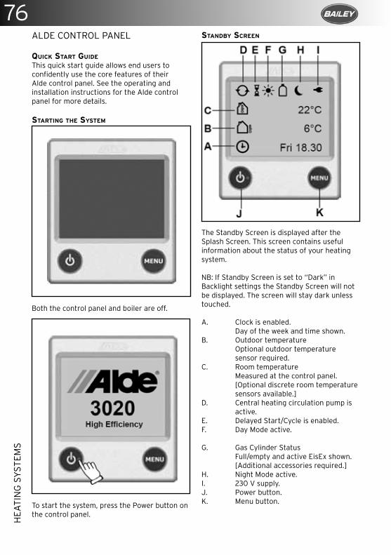
76H
EATI
NG
SY
STEM
S
ALDE CONTROL PANEL
QUICK START GUIDE
This quick start guide allows end users to confidently use the core features of their Alde control panel. See the operating and installation instructions for the Alde control panel for more details.
STARTING THE SYSTEM
Both the control panel and boiler are off.
To start the system, press the Power button on the control panel.
STANDBY SCREEN
The Standby Screen is displayed after the Splash Screen. This screen contains useful information about the status of your heating system.
NB: If Standby Screen is set to “Dark” in Backlight settings the Standby Screen will not be displayed. The screen will stay dark unless touched.
A. Clock is enabled. Day of the week and time shown.B. Outdoor temperature Optional outdoor temperature sensor required.C. Room temperature Measured at the control panel. [Optional discrete room temperature sensors available.]D. Central heating circulation pump is active.E. Delayed Start/Cycle is enabled.F. Day Mode active.
G. Gas Cylinder Status Full/empty and active EisEx shown. [Additional accessories required.]H. Night Mode active.I. 230 V supply.J. Power button.K. Menu button.
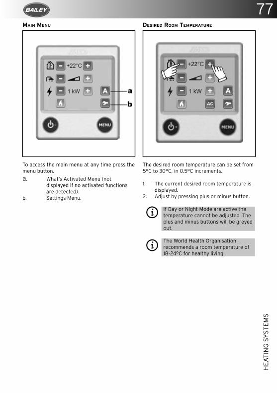
77
HEA
TIN
G S
YST
EMS
MAIN MENU
To access the main menu at any time press the menu button.a. What’s Activated Menu (not displayed if no activated functions are detected).b. Settings Menu.
DESIRED ROOM TEMPERATURE
The desired room temperature can be set from 5°C to 30°C, in 0.5°C increments.
1. The current desired room temperature is displayed.
2. Adjust by pressing plus or minus button.
If Day or Night Mode are active the temperature cannot be adjusted. The plus and minus buttons will be greyed out.
The World Health Organisation recommends a room temperature of 18–24°C for healthy living.
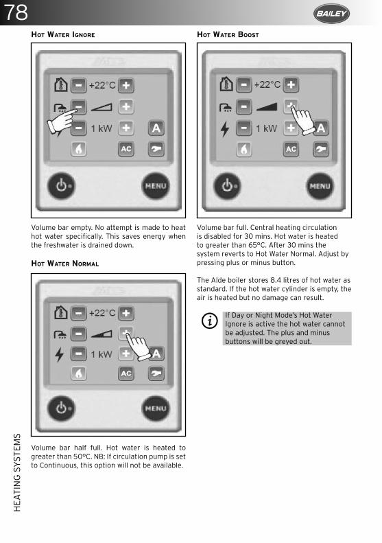
78H
EATI
NG
SY
STEM
S
HOT WATER IGNORE
Volume bar empty. No attempt is made to heat hot water specifically. This saves energy when the freshwater is drained down.
HOT WATER NORMAL
Volume bar half full. Hot water is heated to greater than 50°C. NB: If circulation pump is set to Continuous, this option will not be available.
HOT WATER BOOST
Volume bar full. Central heating circulation is disabled for 30 mins. Hot water is heated to greater than 65°C. After 30 mins the system reverts to Hot Water Normal. Adjust by pressing plus or minus button.
The Alde boiler stores 8.4 litres of hot water as standard. If the hot water cylinder is empty, the air is heated but no damage can result.
If Day or Night Mode’s Hot Water Ignore is active the hot water cannot be adjusted. The plus and minus buttons will be greyed out.
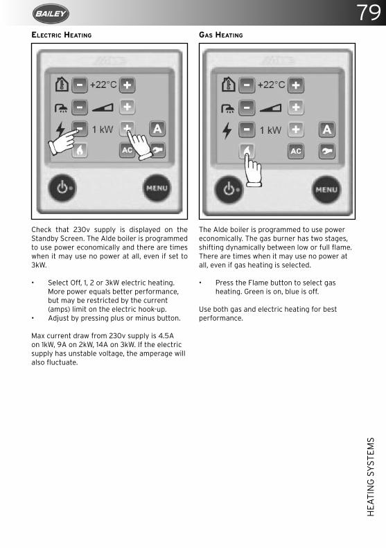
79ELECTRIC HEATING
Check that 230v supply is displayed on the Standby Screen. The Alde boiler is programmed to use power economically and there are times when it may use no power at all, even if set to 3kW.
• Select Off, 1, 2 or 3kW electric heating. More power equals better performance, but may be restricted by the current (amps) limit on the electric hook-up.
• Adjust by pressing plus or minus button.
Max current draw from 230v supply is 4.5A on 1kW, 9A on 2kW, 14A on 3kW. If the electric supply has unstable voltage, the amperage will also fluctuate.
GAS HEATING
The Alde boiler is programmed to use power economically. The gas burner has two stages, shifting dynamically between low or full flame. There are times when it may use no power at all, even if gas heating is selected.
• Press the Flame button to select gas heating. Green is on, blue is off.
Use both gas and electric heating for best performance.
HEA
TIN
G S
YST
EMS
80H
EATI
NG
SY
STEM
S
SHUTTING DOWN THE SYSTEM
To save energy, the control panel only updates the boiler after the last adjustment is made. Wait 10 secs before shutting down the system to ensure the boiler is updated.Press the Power button again. The screen goes dark, the green LED is unlit. The system is off.
SETUP
Most UK installations do not need setting up in the Settings Menu, and use default factory settings.
RESTORE DEFAULT FACTORY SETTINGS
Before using the system for the first time, restore default factory settings. Your control panel may have been tested by the dealer or installer, and some settings may have been changed.Press Tool button to access the Settings Menu (bottom right in Main Menu).Press down arrow, until Reset button is displayed.Press the Reset button to proceed.
SETUP EXPANSION TANK PUMP
To use the 12v circulation pump in the expansion tank, you must set it up. This is not a default factory setting.NB: Under factory settings, the system will use the 12v inline circulation pump by default.Press Tool button to access the Settings Menu (bottom right in Main Menu).Press down arrow, until Circulation Pump button is displayed.Press Circulation Pump button, select Expansion Tank Pump to proceed.
SET UP ANTIMICROBIAL FUNCTION
To actively kill Legionella, set up the Antimicrobial function. At 2:00 every night, the hot water will be heated to over 65°C for 30 mins. This further reduces the risk of Legionella.Press Tool button to access the Settings Menu (bottom right in Main Menu).Press down arrow, until Antimicrobial button is displayed.Press Antimicrobial button to proceed.
SETUP STANDBY SCREEN FOR BEDTIME
The backlight on the Standby Screen can be disturbing if the control panel is visible from your bed. It can be inverted for white text on
black background.Press Tool button to access the Settings Menu (bottom right in Main Menu).Press down arrow, until Backlight button is displayed.Press Backlight button, select Inverted to proceed.
MAINTENANCE
The Alde control panel requires no maintenance, other than cleaning of the screen as needed. Use a microfibre cloth to clean the touchscreen.NB: Consider removing the Alde control panel over winter, if the vehicle is to be kept in storage and is susceptible to damp.
TROUBLESHOOTING
Any error messages will be displayed on the Standby Screen. Error messages can be cleared by switching off 12v supply to the boiler for 10 secs.
The system is completely dead/the control panel is blank.
Check the 20mm T3.15Amp glass fuse in the boiler. This is located under the lid of the black plastic service hatch, in a green plastic fuse holder.Check the 12v supply to the boiler, it should be above 12v.Check the 12v cable is plugged into the boiler. Check the cable is plugged into the Alde control panel.
Panel failure 1 & and Panel failure 2Moisture is trapped in the control panel.Remove the Alde control panel from the vehicle and air in a warm, dry place overnight.
“Gas failure”Out of gas or gas is not igniting.Check the gas cylinder is full. Try a different gas cylinder, ensuring it is propane gas.
Overheat red fail or Overheat blue failBleed the system of air.Check the fluid level in the expansion tank. It should be 1cm above min mark when cool.Check the circulation pump is responding.Wait 15 mins for the fluid to cool down.
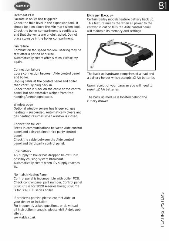
81
HEA
TIN
G S
YST
EMS
Overheat PCBFailsafe in boiler has triggered.Check the fluid level in the expansion tank. It should be 1 cm above the Min mark when cool.Check the boiler compartment is ventilated, and that the vents are unobstructed. Do not place stowage in the boiler compartment.
Fan failureCombustion fan speed too low. Bearing may be stiff after a period of disuse.Automatically clears after 5 mins. Please try again.
Connection failureLoose connection between Alde control panel and boiler.Unplug cable at the control panel and boiler, then carefully plug back in.Check there is slack on the cable at the control panel, but not excessive weight from free-hanging/unmanaged cable.
Window openOptional window sensor has triggered, gas heating is suspended. Automatically clears and gas heating resumes when window is closed.
Connection fail extBreak in communications between Alde control panel and daisy-chained third party control panel.Check the cable between the Alde control panel and third party control panel.
Low battery12v supply to boiler has dropped below 10.5v, possibly causing system brownout.Automatically clears when 12v supply reaches 11v.
No match Heater/PanelControl panel is incompatible with boiler PCB.Check control panel part number. Control panel 3020-013 is for 3020 A-series boiler, 3020-113 is for 3020 HE-series boiler.
If problems persist, please contact Alde, or your dealer or installer.For frequently asked questions, or download all instruction manuals, please visit Alde’s web site at:www.alde.co.uk
BATTERY BACK UP
Certain Bailey models feature battery back up. This feature means the when all power to the caravan is cut or fails the Alde control panel will maintain its memory and settings.
The back up hardware comprises of a lead and a battery holder which accepts x2 AA batteries.
Upon receipt of your caravan you will need to insert x2 AA batteries. The back up module is located behind the cutlery drawer.
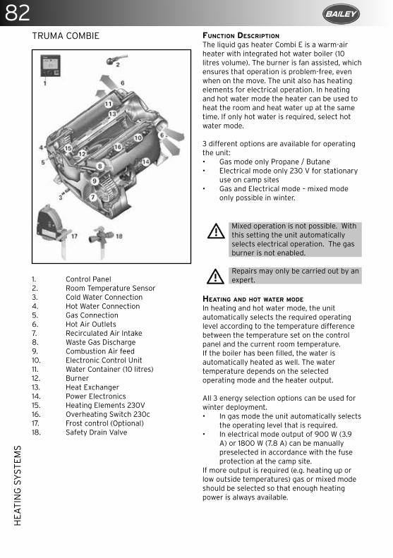
82H
EATI
NG
SY
STEM
S
TRUMA COMBIE
1. Control Panel 2. Room Temperature Sensor3. Cold Water Connection4. Hot Water Connection5. Gas Connection6. Hot Air Outlets7. Recirculated Air Intake8. Waste Gas Discharge9. Combustion Air feed10. Electronic Control Unit11. Water Container (10 litres)12. Burner13. Heat Exchanger14. Power Electronics15. Heating Elements 230V16. Overheating Switch 230c17. Frost control (Optional)18. Safety Drain Valve
FUNCTION DESCRIPTION
The liquid gas heater Combi E is a warm-air heater with integrated hot water boiler (10 litres volume). The burner is fan assisted, which ensures that operation is problem-free, even when on the move. The unit also has heating elements for electrical operation. In heating and hot water mode the heater can be used to heat the room and heat water up at the same time. If only hot water is required, select hot water mode.
3 different options are available for operating the unit:• Gas mode only Propane / Butane• Electrical mode only 230 V for stationary
use on camp sites• Gas and Electrical mode – mixed mode
only possible in winter.
Mixed operation is not possible. With this setting the unit automatically selects electrical operation. The gas burner is not enabled.
Repairs may only be carried out by an expert.
HEATING AND HOT WATER MODE
In heating and hot water mode, the unit automatically selects the required operating level according to the temperature difference between the temperature set on the control panel and the current room temperature. If the boiler has been filled, the water is automatically heated as well. The water temperature depends on the selected operating mode and the heater output.
All 3 energy selection options can be used for winter deployment.• In gas mode the unit automatically selects
the operating level that is required.• In electrical mode output of 900 W (3.9
A) or 1800 W (7.8 A) can be manually preselected in accordance with the fuse protection at the camp site.
If more output is required (e.g. heating up or low outside temperatures) gas or mixed mode should be selected so that enough heating power is always available.
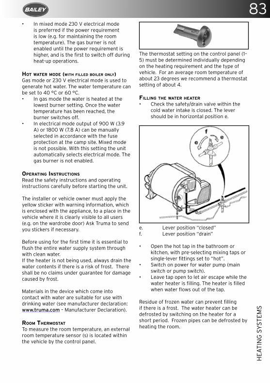
83
HEA
TIN
G S
YST
EMS
• In mixed mode 230 V electrical mode is preferred if the power requirement is low (e.g. for maintaining the room temperature). The gas burner is not enabled until the power requirement is higher, and is the first to switch off during heat-up operations.
HOT WATER MODE (WITH FILLED BOILER ONLY)Gas mode or 230 V electrical mode is used to generate hot water. The water temperature can be set to 40 °C or 60 °C.• In gas mode the water is heated at the
lowest burner setting. Once the water temperature has been reached, the burner switches off.
• In electrical mode output of 900 W (3.9 A) or 1800 W (7.8 A) can be manually selected in accordance with the fuse protection at the camp site. Mixed mode is not possible. With this setting the unit automatically selects electrical mode. The gas burner is not enabled.
OPERATING INSTRUCTIONS
Read the safety instructions and operating instructions carefully before starting the unit.
The installer or vehicle owner must apply the yellow sticker with warning information, which is enclosed with the appliance, to a place in the vehicle where it is clearly visible to all users (e.g. on the wardrobe door) Ask Truma to send you stickers if necessary.
Before using for the first time it is essential to flush the entire water supply system through with clean water.If the heater is not being used, always drain the water contents if there is a risk of frost. There shall be no claims under guarantee for damage caused by frost.
Materials in the device which come into contact with water are suitable for use with drinking water (see manufacturer declaration: www.truma.com – Manufacturer Declaration).
ROOM THERMOSTAT
To measure the room temperature, an external room temperature sensor (s) is located within the vehicle by the control panel.
The thermostat setting on the control panel (1–5) must be determined individually depending on the heating requirement and the type of vehicle. For an average room temperature of about 23 degrees we recommend a thermostat setting of about 4.
FILLING THE WATER HEATER
• Check the safety/drain valve within the cold water intake is closed. The lever should be in horizontal position e.
e. Lever position “closed”f. Lever position “drain”
• Open the hot tap in the bathroom or kitchen, with pre-selecting mixing taps or single-lever fittings set to “hot”.
• Switch on power for water pump (main switch or pump switch).
• Leave tap open to let air escape while the water heater is filling. The heater is filled when water flows out of the tap.
Residue of frozen water can prevent filling if there is a frost. The water heater can be defrosted by switching on the heater for a short period. Frozen pipes can be defrosted by heating the room.
84H
EATI
NG
SY
STEM
S
DRAINING THE WATER HEATER
If the caravan is not used during the winter the boiler must be drained prior to storage
• Disconnect power for water pump.• Open hot the water tap in the bathroom
and kitchen.• Open safety/drain valve: Move the lever to
vertical position f.
The water heater is now drained directly to the outside via the safety/drain valve. Check that the water contents have been completely drained (10 litres).
If just the cold water system is being operated without using the water heater, the heater tank also fills up with water. To avoid frost damage the boiler must be drained through the drain valve even if it was not operated.
When connecting to a central water supply (rural or city mains) a pressure reduction valve must always be installed to prevent above 2.8 bar from developing in the water heater.
There shall be no claims under guarantee for damage caused by frost.
START UP
Heating is possible with gas, electrical and mixed operation. Also with or without water.
Check to make sure the flue is unobstructed. Be sure to remove any covers that may be present.
• Turn on gas cylinder and open isolating tap in the gas supply line.
• Check whether the power supply fuse protection on the camp site is adequate for the 900W (3.9A) or 1800W (7.8A) that has been selected using the power selector switch.
• Fill boiler with water if necessary.• Switch on the unit on the control panel.
SWITCHING OFF
• Switch the heater off on the control panel.• The switch-off procedure may be delayed
by several minutes because of internal heater operations.
Always drain water contents if there is a risk of frost
If the appliance is not used for a long period, close the quick acting valve in the gas supply line and the gas cylinder.
MAINTENANCE
Only original Truma parts may be used for maintenance and repair work.• Clean the compartment where the unit is
installed at least once annually.• Have an expert check the unit for dirt and
clean it if necessary.• The safety/drain valve must be operated
regularly (at least twice annually) to remove limescale deposits and to be certain that it is not blocked.
We recommend the use of suitable commercially available products to clean, sterilise and maintain the boiler. Products containing chlorine are not suitable.
The effectiveness of the use of chemicals to combat micro-organisms in the appliance can be increased by heating the water in the boiler to 70 °C at regular intervals.
• Select “Gas mode”.• Set the water temperature to 60 °C.• Switch on the appliance.
Once the water in the boiler has reached a temperature of 60 °C, the burner will switch off. The appliance must stay switched on for at least 30 minutes and no hot water may be removed. The residual heat in the heat exchanger will heat the water up to 70 °C.
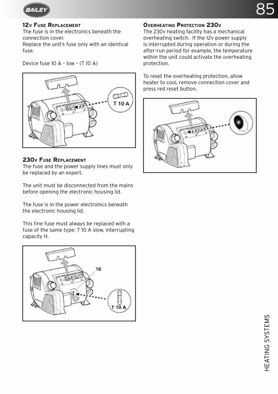
85
HEA
TIN
G S
YST
EMS
12V FUSE REPLACEMENT The fuse is in the electronics beneath the connection cover.Replace the unit’s fuse only with an identical fuse.
Device fuse 10 A – low – (T 10 A)
230V FUSE REPLACEMENT
The fuse and the power supply lines must only be replaced by an expert.
The unit must be disconnected from the mains before opening the electronic housing lid.
The fuse is in the power electronics beneath the electronic housing lid.
This fine fuse must always be replaced with a fuse of the same type: T 10 A slow, interrupting capacity H.
OVERHEATING PROTECTION 230V
The 230v heating facility has a mechanical overheating switch. If the 12v power supply is interrupted during operation or during the after-run period for example, the temperature within the unit could activate the overheating protection.
To reset the overheating protection, allow heater to cool, remove connection cover and press red reset button.
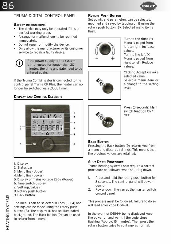
86H
EATI
NG
SY
STEM
S
TRUMA DIGITAL CONTROL PANEL
SAFETY INSTRUCTIONS
• The device may only be operated if it is in perfect working order.
• Arrange for malfunctions to be rectified immediately.
• Do not repair or modify the device.• Only allow the manufacturer or its customer
service to repair a faulty device.
If the power supply to the system is interrupted for longer than 20 minutes, the time and date need to be entered again.
If the Truma Combi heater is connected to the control panel Truma CP Plus, the heater can no longer be switched via a ZUCB timer.
DISPLAY AND CONTROL ELEMENTS
1. Display2. Status bar3. Menu line (Upper)4. Menu line (Lower)5. Display of mains voltage 230v (Power)6. Time switch display7. Settings/values8. Rotary push button9. Back button
The menus can be selected in lines (3 + 4) and settings can be made using the rotary push button (8). The display (1) has an illuminated background. The Back button (9) can be used to return from a menu.
ROTARY PUSH BUTTON
Set points and parameters can be selected, modified and saved by tapping on it using the rotary push button (8). Selected menu items flash.
BACK BUTTON
Pressing the Back button (9) returns you from a menu and discards settings. This means that the previous values are retained.
SHUT DOWN PROCEDURE
Truma heating systems now require a correct procedure be followed when shutting down.
1. Press and hold the rotary push button for 3 seconds. The control panel will power down.
2. Power down the van at the master switch control panel.
This process must be followed. Failure to do so will lead error code E-514-H.
In the event of E-514-H being displayed keep the power on and wait till the code stops flashing (Approx. 15 minutes). Then press the rotary button twice to continue as normal.
Turn to the right (+)Menu is paged from left to right. Increase values.Turn to the left (–)Menu is paged from right to left. Reduce values.
Clicking Accept (save) a selected value.Select a menu item or a change to the setting level.
Press (3 seconds) Main switch function ON/OFF
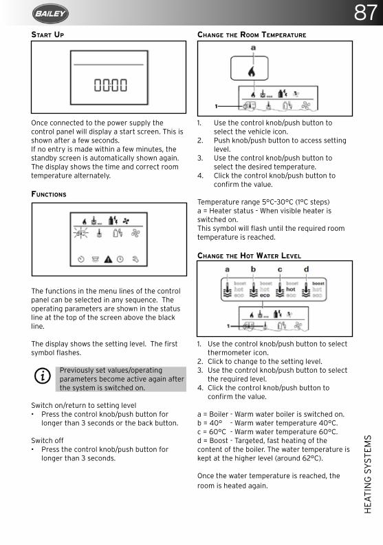
87
HEA
TIN
G S
YST
EMS
START UP
Once connected to the power supply the control panel will display a start screen. This is shown after a few seconds.If no entry is made within a few minutes, the standby screen is automatically shown again. The display shows the time and correct room temperature alternately.
FUNCTIONS
The functions in the menu lines of the control panel can be selected in any sequence. The operating parameters are shown in the status line at the top of the screen above the black line.
The display shows the setting level. The first symbol flashes.
Previously set values/operating parameters become active again after the system is switched on.
Switch on/return to setting level• Press the control knob/push button for
longer than 3 seconds or the back button.
Switch off• Press the control knob/push button for
longer than 3 seconds.
CHANGE THE ROOM TEMPERATURE
1. Use the control knob/push button to select the vehicle icon.
2. Push knob/push button to access setting level.
3. Use the control knob/push button to select the desired temperature.
4. Click the control knob/push button to confirm the value.
Temperature range 5°C–30°C (1°C steps)a = Heater status - When visible heater is switched on.This symbol will flash until the required room temperature is reached.
CHANGE THE HOT WATER LEVEL
1. Use the control knob/push button to select thermometer icon.
2. Click to change to the setting level.3. Use the control knob/push button to select
the required level.4. Click the control knob/push button to
confirm the value.
a = Boiler - Warm water boiler is switched on.b = 40° - Warm water temperature 40°C.c = 60°C - Warm water temperature 60°C.d = Boost - Targeted, fast heating of the content of the boiler. The water temperature is kept at the higher level (around 62°C).
Once the water temperature is reached, the room is heated again.
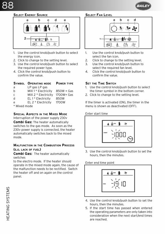
88H
EATI
NG
SY
STEM
S
SELECT ENERGY SOURCE
1. Use the control knob/push button to select the energy icon.
2. Click to change to the setting level.3. Use the control knob/push button to select
the required power type.4. Click the control knob/push button to
confirm the value.
SYMBOL OPERATING MODE POWER TYPE
a LP gas LP gasb MIX 1 * Electricity 850W + Gasc MIX 2 * Electricity 1700W+ Gasd EL 1 * Electricity 850We EL 2 * Electricity 1700W* Mixed mode
SPECIAL ASPECTS IN THE MIXED MODE
Interruption of the power supply 230vCombi Gas: The heater automatically switches to the gas mode. As soon as the 230v power supply is connected, the heater automatically switches back to the mixed mode.
MALFUNCTION IN THE COMBUSTION PROCESS (E.G. LACK OF FUEL)Combi Gas: The heater automatically switches to the electro mode. If the heater should operate in the mixed mode again, the cause of the malfunction needs to be rectified. Switch the heater off and on again on the control panel.
SELECT FAN LEVEL
1. Use the control knob/push button to select the fan icon.
2. Click to change to the setting level.3. Use the control knob/push button to
select the required fan level.4. Click the control knob/push button to
confirm the value.
SET THE TIME SWITCH 1. Use the control knob/push button to select
the timer symbol in the bottom corner.2. Click to change to the setting level.
If the timer is activated (ON), the timer in the menu is shown as deactivated (OFF).
Enter start time
3. Use the control knob/push button to set the hours, then the minutes.
Enter end time point
4. Use the control knob/push button to set the hours, then the minutes.
5. If the start time has passed when entered the operating parameters are only taken into consideration when the next start/end times are reached.
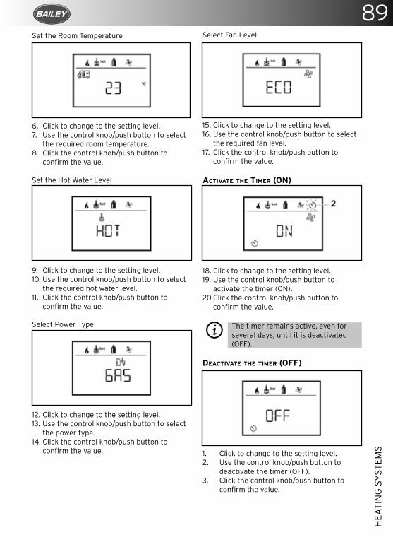
89
HEA
TIN
G S
YST
EMS
Set the Room Temperature
6. Click to change to the setting level.7. Use the control knob/push button to select
the required room temperature.8. Click the control knob/push button to
confirm the value.
Set the Hot Water Level
9. Click to change to the setting level.10. Use the control knob/push button to select
the required hot water level.11. Click the control knob/push button to
confirm the value.
Select Power Type
12. Click to change to the setting level.13. Use the control knob/push button to select
the power type.14. Click the control knob/push button to
confirm the value.
Select Fan Level
15. Click to change to the setting level.16. Use the control knob/push button to select
the required fan level.17. Click the control knob/push button to
confirm the value. ACTIVATE THE TIMER (ON)
18. Click to change to the setting level.19. Use the control knob/push button to
activate the timer (ON).20. Click the control knob/push button to
confirm the value.
The timer remains active, even for several days, until it is deactivated (OFF).
DEACTIVATE THE TIMER (OFF)
1. Click to change to the setting level.2. Use the control knob/push button to
deactivate the timer (OFF).3. Click the control knob/push button to
confirm the value.
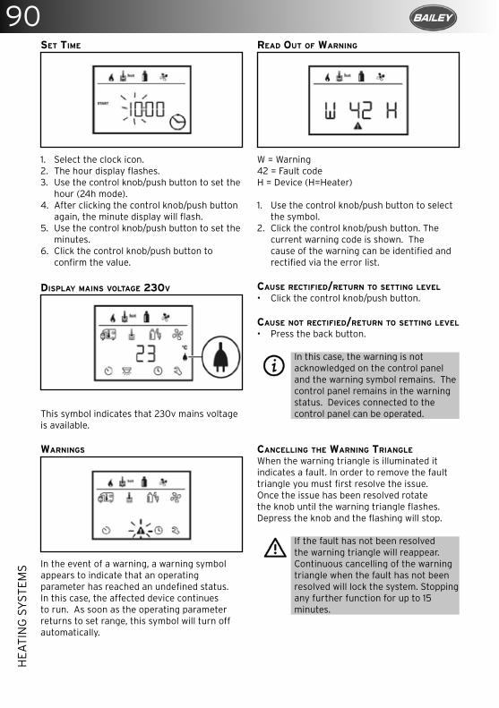
90H
EATI
NG
SY
STEM
S
READ OUT OF WARNING
W = Warning42 = Fault codeH = Device (H=Heater)
1. Use the control knob/push button to select the symbol.
2. Click the control knob/push button. The current warning code is shown. The cause of the warning can be identified and rectified via the error list.
CAUSE RECTIFIED/RETURN TO SETTING LEVEL
• Click the control knob/push button.
CAUSE NOT RECTIFIED/RETURN TO SETTING LEVEL
• Press the back button.
In this case, the warning is not acknowledged on the control panel and the warning symbol remains. The control panel remains in the warning status. Devices connected to the control panel can be operated.
CANCELLING THE WARNING TRIANGLE
When the warning triangle is illuminated it indicates a fault. In order to remove the fault triangle you must first resolve the issue.Once the issue has been resolved rotate the knob until the warning triangle flashes. Depress the knob and the flashing will stop.
If the fault has not been resolved the warning triangle will reappear. Continuous cancelling of the warning triangle when the fault has not been resolved will lock the system. Stopping any further function for up to 15 minutes.
SET TIME
1. Select the clock icon.2. The hour display flashes.3. Use the control knob/push button to set the
hour (24h mode).4. After clicking the control knob/push button
again, the minute display will flash.5. Use the control knob/push button to set the
minutes.6. Click the control knob/push button to
confirm the value.
DISPLAY MAINS VOLTAGE 230V
This symbol indicates that 230v mains voltage is available.
WARNINGS
In the event of a warning, a warning symbol appears to indicate that an operating parameter has reached an undefined status. In this case, the affected device continues to run. As soon as the operating parameter returns to set range, this symbol will turn off automatically.
91
EXTE
RIO
R F
EATU
RES
EXTERIOR FEATURES
GRP
GRP components need to be washed, waxed and cared for like a car. Chemicals and dirt can collect during storage, and the outer surface called a gel coat can be stained or marked when chemicals combine with rain or dew. Most stains or marks can be removed with mild dish-washing detergent, but more stubborn marks may require a rubbing compound. To help keep your GRP components looking almost like new, it is wise to wash the parts monthly (or more frequently) using mild dish-washing detergent, but avoid using strong alkaline (e.g. tri-sodium phosphate) or acidic cleaners or abrasives. Waxing the components once or twice a year with a good grade paste wax will help to maintain the colour and finish.
ROOFLIGHTS
HEKI ROOFLIGHTS:OPENING IN THE TILT SETTING 1. Press the locking buttons at both catches
on the glass and turn inwards through approx. 90°.
2. Grasp the bar in the middle, unclasp from the anchoring fasteners, swivel the bar down and push the glass dome upwards. (Glass dome is assisted after approx. 150mm by the two pneumatic springs.)
3. Swivel the bar towards the glass dome and clip into position.
4. To close the HEKI, perform steps (1–3) in reverse order.
OPENING IN THE INTERMEDIATE SETTING 1. Open both catches on the glass. 2. Grasp the bar in the middle, unclasp from
the anchoring fasteners, swivel down and push the glass dome upwards. (Glass dome opens automatically after approx. 150mm through the two pneumatic springs.)
3. Open both fasteners, and swivel the bar towards the intermediate setting and pull the glass dome down until the bar rests in the hold.
4. Secure the bar with the two fasteners.5. To close HEKI, perform steps (1–4) in
reverse order.
OPENING IN PERMANENT VENTILATION SETTING
1. Open both catches on the glass.2. Push glass dome up approx. 2cm with
both hands on the two catches and turn the catches to fix them in the ventilation setting.
3. To close HEKI, perform steps (a–b) in reverse order.
CLOSING THE BLIND
1. To close the blind, grasp the end rod (without grip) in the recess and engage in the opposite end rod (with grip).
2. You can move both joined end rods to adjust the blind to the required position (black out/fly screen/sun shade).
92EX
TER
IOR
FEA
TUR
ES
OPENING THE BLIND
1. Move the blind right out to the side (end rod with grip).
2. Holding the recess with one hand, press the rocker with the other hand and guide the blind back into position.
SAFETY INSTRUCTIONS
• Do not stand on the acrylic glass.• Close HEKI completely before moving the
vehicle.• Close HEKI when leaving the vehicle.• Please consult your dealer when any
defects or problems occur.• Remove snow/ice or other dirt from the
roof before opening HEKI.• Do not open in strong winds or heavy rain.
CARE INSTRUCTIONS
• Please clean the acrylic panes with the Seitz Acrylic Cleaner.
• Stains and light scratches on the acrylic pane can be removed using the Seitz Acrylic Polish and Seitz special polishing cloth.
• Only use water and mild soap suds to clean the blinds.
• Failure to comply with these instructions will make the warranty null and void.
MPK ROOFLIGHT
The MPK rooflight is situated in the bathroom of your caravan over the shower compartment.It is fitted with a fly screen for your comfort. The fly screen is hinged, allowing you access to the handles that enable you to raise the rooflight’s dome for ventilation.
To raise the dome pinch the black parts of the handle against the other half on both sides and push upwards. Both sides can be raised or just one, depending on your preference.

93
CO
OK
ING
EQ
UIP
MEN
T
COOKING EQUIPMENT
Never use oversized pans as this will lead to damage within the caravan.
• Each burner will support pans from Ø10 to Ø18cm; care should be taken not to overload the appliance as performance may be reduced.
• The following pan sizes are the maximum we recommend:
• Electric hotplate: - Ø180mm (Dual Fuel only)
• Auxiliary burner: Ø180mm• Semi-rapid burner: 2x Ø180mm or 1x
Ø180mm with 1x Ø180mm• When using small pans the flames should
not spread beyond the base of the pan as this will reduce the efficiency of the burner.
• Avoid old or misshapen pans as these may cause instability.
• The lid must be opened fully prior to using the hotplate burners.
• For guaranteed damage free cooking it is recommended you use Ø180mm pans.
Never use the cooker as a space heater
Before using the appliance please ensure that you are aware of the following:
• Appliance and accessible parts become hot during use.
• Avoid touching heating elements.• Children less than 8 years of age shall be
kept away unless continuously supervised. This appliance can be used by children aged 8 years and above, persons with reduced physical, sensory or mental capabilities and/or lack of experience and knowledge only if they
have been given supervision or instruction concerning use of the appliance in a safe way and understand the hazards involved.
• Children shall not play with the appliance.• Cleaning and user maintenance shall not be
made by children without supervision.• Unattended cooking on a hob with fat or oil
can be dangerous and may result in fire.• Never extinguish a fire with water; switch
off the appliance and cover flame with lid or fire blanket.
• Danger of fire: Do not store items on the cooking surface.
• Do not use harsh abrasive cleaners or sharp metal scrapers to clean the oven door glass since they can scratch the surface, which may result in shattering of the glass.
• Never use a steam cleaner to clean the appliance.
OPERATION
The burners on this appliance have fixed aeration and no adjustment is required. The burners should flame as follows:Propane: The flames should burn quietly with a blue/green colour with no sign of yellow tips.Butane: Normally, on initial lighting, a small amount of yellow tipping will occur. This then increases slightly as the burner heats up.
USING THE HOTPLATE GAS BURNERS
Ensure that the glass lid is open before turning on the burners.
• Glass lids may shatter when heated. • Turn off all burners before shutting the
lid.• The glass lid has a tendency to snap shut
towards the lowered position. Ensure fingers are away from the entrapment area when closing the lid.
• Remove all spillages from the glass lid before opening.
• Children should be supervised to ensure that they do not play with the appliance.
• Ensure gas cylinder/supply is connected and turned on. In the event of a gas smell turn off at gas cylinder/mains and contact supplier.
• Flame supervision: each burner is controlled individually and is monitored by a thermocouple probe. In the event of the burner flames being accidentally extinguished, turn off the burner control and do not attempt to re-ignite the burner for at least one minute.
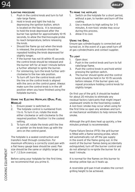
94C
OO
KIN
G E
QU
IPM
ENT
LIGHTING PROCEDURE 1. Push in the control knob and turn to full
rate–large flame. 2. Hold in knob and light the hob by
depressing the ignition button, which is located on the fascia. It is necessary to hold the knob depressed after the burner has ignited for approximately 10–15 seconds, to allow the thermocouple probe to reach temperature, before releasing the knob.
• Should the flame go out when the knob is released, the procedure should be repeated holding the knob depressed for slightly longer.
• If the burner has not lit within 15 seconds the control knob should be released and the burner left for at least 1 minute before a further attempt to ignite the burner.
• For simmering, turn the knob further anti-clockwise to the low rate position.
• To turn off: turn the control knob until the line on the control knob is aligned with the zero on the control panel. Always make sure the control knob is in the off position when you have finished using the hotplate burners.
USING THE ELECTRIC HOTPLATE (DUAL FUEL MODELS)1. Ensure power is switched on. 2. The hotplate control is numbered from
1 to 6. To turn it on, rotate the knob either clockwise or anti-clockwise to the required position. Position 1 is the coolest setting.
3. To turn off, rotate the knob until the line or pointer on the knob lines up with the zero on the control panel.
The hotplate is a sealed construction and transfers heat through conduction. For maximum efficiency a correctly sized pan with a flat heavy gauge base should be used. Pan size should be the same or slightly larger (up to 1” / 2.5cm oversize).
Before using your hotplate for the first time, we recommend that you prime it.
TO PRIME THE HOTPLATE
1. Switch on the hotplate for a short period, without a pan, to harden and burn off the coating.
2. Use a medium to high setting for 3–5 minutes. A non-toxic smoke may occur during this process.
3. Allow it to cool.
USING THE GRILL
Ensure gas cylinder/supply is connected and turned on. In the event of a gas smell turn off at gas cylinder/mains and contact supplier.
TO LIGHT 1. Open door. 2. Push in the control knob and turn to full
rate/large flame. 3. Push the control knob in and hold whilst
pressing the ignition switch.4. The burner should ignite and the control
knob should be held in for 10–15 seconds before release. If the burner goes out, repeat procedure holding control knob for slightly longer.
On first use of the grill, it should be heated for about 20 minutes to eliminate any residual factory lubricants that might impart unpleasant smells to the food being cooked. A non-toxic smoke may occur when using for the first time so open any windows and turn on mechanical ventilators to help remove the smoke.
Although the grill does heat up quickly, a few minutes preheat is recommended.
Flame Failure Device (FFD): the grill burner is fitted with a flame-sensing probe, which will automatically cut off the gas supply in the event of the flame going out. In the event of the burner flames being accidentally extinguished, turn off the burner control and do not attempt to re-ignite the burner for at least 1 minute. It is normal for the flames on this burner to develop yellow tips as it heats up.
A reversible grill pan trivet enables the correct grilling height to be achieved.
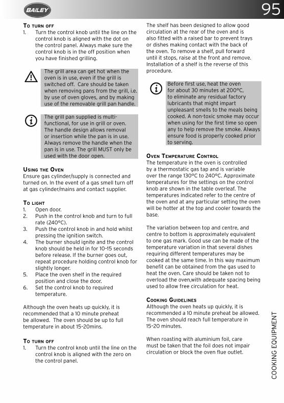
95
CO
OK
ING
EQ
UIP
MEN
T
TO TURN OFF
1. Turn the control knob until the line on the control knob is aligned with the dot on the control panel. Always make sure the control knob is in the off position when you have finished grilling.
The grill area can get hot when the oven is in use, even if the grill is switched off. Care should be taken when removing pans from the grill, i.e. by use of oven gloves, and by making use of the removable grill pan handle.
The grill pan supplied is multi-functional, for use in grill or oven. The handle design allows removal or insertion while the pan is in use. Always remove the handle when the pan is in use. The grill MUST only be used with the door open.
USING THE OVEN
Ensure gas cylinder/supply is connected and turned on. In the event of a gas smell turn off at gas cylinder/mains and contact supplier.
TO LIGHT 1. Open door. 2. Push in the control knob and turn to full
rate (240°C).3. Push the control knob in and hold whilst
pressing the ignition switch. 4. The burner should ignite and the control
knob should be held in for 10–15 seconds before release. If the burner goes out, repeat procedure holding control knob for slightly longer.
5. Place the oven shelf in the required position and close the door.
6. Set the control knob to required temperature.
Although the oven heats up quickly, it is recommended that a 10 minute preheat be allowed. The oven should be up to full temperature in about 15–20mins.
TO TURN OFF
1. Turn the control knob until the line on the control knob is aligned with the zero on the control panel.
The shelf has been designed to allow good circulation at the rear of the oven and is also fitted with a raised bar to prevent trays or dishes making contact with the back of the oven. To remove a shelf, pull forward until it stops, raise at the front and remove. Installation of a shelf is the reverse of this procedure.
Before first use, heat the oven for about 30 minutes at 200°C, to eliminate any residual factory lubricants that might impart unpleasant smells to the meals being cooked. A non-toxic smoke may occur when using for the first time so open any to help remove the smoke. Always ensure food is properly cooked prior to serving.
OVEN TEMPERATURE CONTROL
The temperature in the oven is controlled by a thermostatic gas tap and is variable over the range 130°C to 240°C. Approximate temperatures for the settings on the control knob are shown in the table overleaf. The temperatures indicated refer to the centre of the oven and at any particular setting the oven will be hotter at the top and cooler towards the base.
The variation between top and centre, and centre to bottom is approximately equivalent to one gas mark. Good use can be made of the temperature variation in that several dishes requiring different temperatures may be cooked at the same time. In this way maximum benefit can be obtained from the gas used to heat the oven. Care should be taken not to overload the oven,with adequate spacing being used to allow free circulation for heat.
COOKING GUIDELINES
Although the oven heats up quickly, it is recommended a 10 minute preheat be allowed. The oven should reach full temperature in 15–20 minutes.
When roasting with aluminium foil, care must be taken that the foil does not impair circulation or block the oven flue outlet.
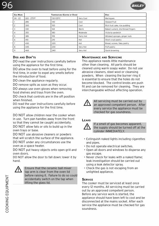
96C
OO
KIN
G E
QU
IPM
ENT
DOS AND DON’TS
DO read the user instructions carefully before using the appliance for the first time.DO allow the oven to heat before using for the first time, in order to expel any smells before the introduction of food.DO clean the appliance regularly.DO remove spills as soon as they occur.DO always use oven gloves when removing food shelves and trays from the oven.DO check that controls are in the off position when finished.DO read the user instructions carefully before using the appliance for the first time.
DO NOT allow children near the cooker when in use. Turn pan handles away from the front so that they cannot be caught accidentally.DO NOT allow fats or oils to build up in the oven trays or base.DO NOT use abrasive cleaners or powders that will scratch the surface of the appliance.DO NOT under any circumstances use the oven as a space heater.DO NOT put heavy objects onto open grill and oven doors.DO NOT allow the door to fall down: lower it by hand.
Ensure that the ceramic ball mixer tap arm is clear from the oven lid before raising it. Failure to do so could accidentally switch on the tap when lifting the glass lid.
MAINTENANCE AND SERVICING
This appliance needs little maintenance other than cleaning. All parts should be cleaned using warm soapy water. Do not use abrasive cleaners, steel wool or cleansing powders. When cleaning the burner ring it is essential to ensure that the holes do not become blocked. The control knobs are push fit and can be removed for cleaning. They are interchangeable without affecting operation.
All servicing must be carried out by an approved competent person. After every service the appliance must be checked for gas soundness.
LEAKS
If a smell of gas becomes apparent, the supply should be turned off at the cylinder IMMEDIATELY.
• Extinguish naked lights including cigarettes
and pipes. • Do not operate electrical switches. • Open all doors and windows to disperse any
gas escape. • Never check for leaks with a naked flame;
leak investigation should be carried out using a leak detector spray.
• Check the gas is not escaping from an unlighted appliance.
SERVICE
The cooker must be serviced at least once every 12 months. All servicing must be carried out by an approved competent person. Before any service work is started, the appliance should have been left to cool and be disconnected at the mains socket. After each service the appliance must be checked for gas soundness.
GAS MARK TEMPERATURE (CENTRE OF OVEN) DISH
1/4 - 1/2 265 - 275°F 130-135°C Very Cool Meringues
1 285 140 Cool Stewed Fruit
2 300 150 Cool Rich fruit cake, rice pudding
3 330 165 Warm Baked custard, shortbread fingers
4 355 180 Moderate Victoria sandwich
5 385 195 Fairly Hot Whisked sponges, ginger nuts
6 410 210 Hot Short crust pastry
7 430 220 Hot Bread, scones, flaky pastry
8 445 230 Very Hot Puff pastry
9 465 240 Very Hot Quick browning
97
CO
OK
ING
EQ
UIP
MEN
T
For service, please contact your authorised local service agent giving details of the model and serial number on the data badge plus date of purchase.
Some Bailey caravan models have both a worktop lid and glass lid covering the hob burners. Please be aware that both the glass and worktop lids may become hot during the use of the grill and/or oven. Therefore Bailey and Thetford strongly advise you lift both lids up when using the grill and/or oven to avoid any potential product/injury issues.
98C
AR
BO
N M
ON
OX
IDE
ALA
RM
Please read all steps thoroughly before attempting to test your alarm.
• If the alarm is wall mounted, remove by unhooking the unit from the wall fixing screws.
• Cover the sounder vents with one hand and hold the Test/Reset button down with your thumb/finger until the power LED illuminates green and the sounder sounds for a second time. (This should happen after 5 seconds.) Release the Test/Reset button and the power LED will flash green once every second. This indicates that the sampling rate of the detector has increased and can be tested using a known source of CO.
• Light an incense stick or a cigarette using a match or a lighter. If using an incense stick, be sure to blow the flame out so that the incense stick is smouldering. Extinguish the lighter, or put out the match and place it into a dish of water.
• Turn the detector on its side so that the vents on the right hand side of the detector are pointing downwards. Hold the burning incense stick or cigarette around 15cm (6”) below the detector. An increase in the localised carbon monoxide level within the sensor to more than 50ppm will cause the sounder to sound for one cycle of four loud beeps. The power LED will no longer flash green every second but will revert to flashing once a minute. The detector will revert back to the ordinary operating mode (it may take up to 2 minutes for the localised level of carbon monoxide to fall below 50ppm). Now move the source of CO away from the detector as the test is finished.
• Put out the incense stick or cigarette by placing it into a dish of water. Ensure all flames have been extinguished.
If the localised carbon monoxide level within the sensor does not reach 50ppm during the test, the sensor test will stop automatically after 3 minutes.
UNDERSTANDING YOUR PRODUCT’S INDICATORS
The higher the concentration of carbon monoxide detected by the detector, the quicker it will respond. When sufficient carbon monoxide is detected a loud audible signal
CARBON MONOXIDE ALARM
A FireAngel CO-9B battery-operated alarm is fitted near to the ceiling in your caravan.
FEATURES
• An advanced electro-chemical sensor designed to accurately measure low–high levels of carbon monoxide (CO) providing an early warning of toxic CO levels in your caravan.
• Detects carbon monoxide continuously.• Resistant to false alarms caused by usual
household contaminants.• Sounds a large 85dB alarm (at 1 metre (3
feet)) to alert you in case of an emergency.• Test/Reset button.• Simple to mount, portable, ideal for
travelling.• Conforms to the British Standards Institute
(BSi) Carbon Monoxide Standard BS EN 50291: 2001.
• 7 year warranty.• Test the sounder, batteries and circuitry.• Allows you to test the sensor by introducing
a source of CO into the detector.• Silence the loud 85dB sounder during an
alarm (only possible when current CO level is less than 50ppm (Parts Per Million the accepted level of carbon monoxide in the air)).
TESTING THE SOUNDER BATTERIES AND CIRCUITRY
• Test the sounder, batteries and circuitry by pressing and holding the Test/Reset button for 1 second to confirm that the detector is operating properly. The sounder should sound as soon as the button is pressed, and the alarm LED will illuminate red, indicating that the sounder is working and the batteries are providing power to the unit. The test for the sounder batteries and circuitry should be performed weekly.
TESTING THE SENSOR
• All sensor testing should be carried out by a responsible adult. This test should only be performed once a month. Excessive testing will cause the battery life to be shortened.
CO testers may be used in order to avoid having to burn cigarettes, incense sticks etc.
99
CA
RB
ON
MO
NO
XID
E A
LAR
M
Do not attempt to repair your CO detector. Do not remove any screws or open the main casing of your detector. Any attempt to do so may cause malfunction and will invalidate the warranty.
WHAT TO DO IN THE EVENT OF AN ALARM
• Keep calm and open all the doors and windows to ventilate your caravan.
• Stop using all fuel burning appliances and ensure where possible they are turned off.
• Evacuate the caravan leaving doors and windows open.
• Do not re-enter the caravan until the alarm has stopped.
• Get medical help for anyone suffering the effects of CO poisoning and advise that CO poisoning is suspected.
• Do not use the caravan again until you have had a full service of all appliances by your supplying retailer. In the case of gas appliances they must be tested by a GAS SAFE registered installer. Please contact your Bailey retailer for more details.
• The electro-chemical sensors used in the carbon-monoxide alarm have a limited lifespan–therefore it is recommended that a CO alarm is replaced every 5–7 years after manufacture or in accordance with the unit’s instructions. Check the manufacturing date on the alarm’s label.
(85dB at 1m/3ft) will be emitted and the alarm LED will flash red once every second.The alarm will sound:
• Between 60 and 90 minutes when exposed to 50ppm of CO.
• Between 10 and 40 minutes when exposed to 100ppm of CO.
• Within 3 minutes when exposed to 300ppm or more CO.
• There will be an audible “chirp” if the battery, sensor or circuitry has any fault including a low battery. This sound will continue once a minute for 30 days. (The battery must be replaced to ensure occupant safety.)
• If the device continues to chirp despite having new batteries and the product is still in warranty then contact technical support for the device. If the device is no longer in warranty replace it immediately.
MAINTAINING AND TESTING YOUR DETECTOR
Your detector will alert you to potential hazardous CO concentrations in your caravan when maintained properly. To maintain your FireAngel detector in proper working order and to ensure that the sensors will last for the lifetime of the product, it is recommended that you:
• Test the sounder, batteries and circuitry of your detector once per week by pressing and holding the Test/Reset button for 1 second.
• Keep the detector free of dust by gently vacuuming with a soft brush attachment when required.
To prevent the possibility of contaminating the sensor in your detector and thus affecting its reliability:
• Never use cleaning solutions on your detector. Simply wipe with a damp cloth.
• Do not paint the detector.• Do not spray aerosols on or near to the
detector.• Do not use any solvent based products near
to the detector
Failure of any test should be reported to the manufacturer’s technical support line. +44 (0)800 141 2561
100C
AR
BO
N M
ON
OX
IDE
ALA
RM
SIMPLE MAINTENANCE
Clean your smoke alarm once every three months to help keep the unit working correctly. Gently vacuum using a soft brush attachment.
Problems are indicated by two events:The alarm does not sound upon pressing the test button. The operating light remains steadily on or off (i.e. does not flash every 40 seconds, when the unit is not sounding).
Try the following:• Inspect for obvious damage.• Check that the unit contains
recommended battery type.• Check that the battery cover has been
removed.• Check that the battery is properly
connected.• Gently vacuum as recommended above.• Replace battery.
If these procedures do not correct the problem, do NOT attempt repairs; replace the alarm.
SMOKE ALARM
The smoke alarm is operational once the battery is connected. When products of combustion are sensed, the unit sounds an alarm until the air is cleared.
FEATURES
• Battery operated.• The operating light (red LED) flashes
every 40 seconds confirming that the unit is powered.
• Low battery warning: the unit will emit an audible “chirp” once every 40 seconds for 7 days before the battery needs to be replaced. Failure to replace the battery will result in insufficient power to alert you in a real fire situation.
• Sensitivity test button. This tests the sensitivity, circuitry, battery and horn.
• Loud alarm
Test smoke operation after vehicle has been in storage, before each trip and at least once a week during use.
Your alarm requires one 9 volt battery. Under normal use, the battery should last one year.
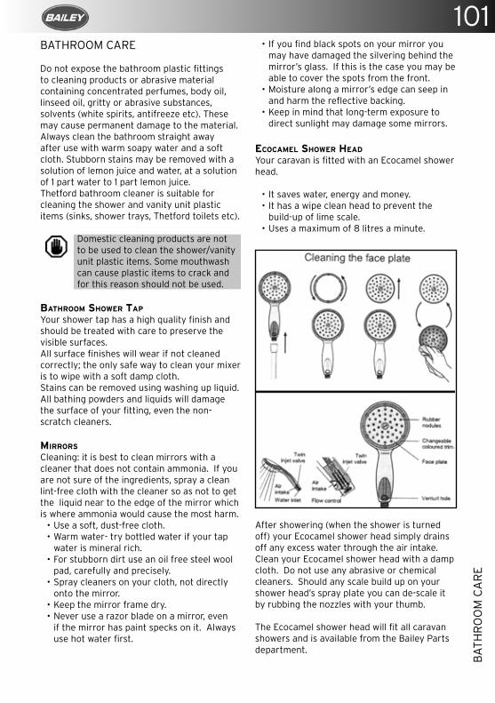
101
BA
THR
OO
M C
AR
E
BATHROOM CARE
Do not expose the bathroom plastic fittings to cleaning products or abrasive material containing concentrated perfumes, body oil, linseed oil, gritty or abrasive substances, solvents (white spirits, antifreeze etc). These may cause permanent damage to the material. Always clean the bathroom straight away after use with warm soapy water and a soft cloth. Stubborn stains may be removed with a solution of lemon juice and water, at a solution of 1 part water to 1 part lemon juice.Thetford bathroom cleaner is suitable for cleaning the shower and vanity unit plastic items (sinks, shower trays, Thetford toilets etc).
Domestic cleaning products are not to be used to clean the shower/vanity unit plastic items. Some mouthwash can cause plastic items to crack and for this reason should not be used.
BATHROOM SHOWER TAP
Your shower tap has a high quality finish and should be treated with care to preserve the visible surfaces.All surface finishes will wear if not cleaned correctly; the only safe way to clean your mixer is to wipe with a soft damp cloth.Stains can be removed using washing up liquid.All bathing powders and liquids will damage the surface of your fitting, even the non-scratch cleaners.
MIRRORS
Cleaning: it is best to clean mirrors with a cleaner that does not contain ammonia. If you are not sure of the ingredients, spray a clean lint-free cloth with the cleaner so as not to get the liquid near to the edge of the mirror which is where ammonia would cause the most harm.
• Use a soft, dust-free cloth.• Warm water- try bottled water if your tap
water is mineral rich.• For stubborn dirt use an oil free steel wool
pad, carefully and precisely.• Spray cleaners on your cloth, not directly
onto the mirror.• Keep the mirror frame dry.• Never use a razor blade on a mirror, even
if the mirror has paint specks on it. Always use hot water first.
• If you find black spots on your mirror you may have damaged the silvering behind the mirror’s glass. If this is the case you may be able to cover the spots from the front.
• Moisture along a mirror’s edge can seep in and harm the reflective backing.
• Keep in mind that long-term exposure to direct sunlight may damage some mirrors.
ECOCAMEL SHOWER HEAD
Your caravan is fitted with an Ecocamel shower head.
• It saves water, energy and money.• It has a wipe clean head to prevent the
build-up of lime scale.• Uses a maximum of 8 litres a minute.
After showering (when the shower is turned off) your Ecocamel shower head simply drains off any excess water through the air intake.Clean your Ecocamel shower head with a damp cloth. Do not use any abrasive or chemical cleaners. Should any scale build up on your shower head’s spray plate you can de-scale it by rubbing the nozzles with your thumb.
The Ecocamel shower head will fit all caravan showers and is available from the Bailey Parts department.
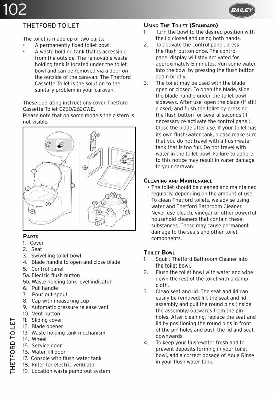
102TH
ETFO
RD
TO
ILET
THETFORD TOILET
The toilet is made up of two parts:• A permanently fixed toilet bowl.• A waste holding tank that is accessible
from the outside. The removable waste holding tank is located under the toilet bowl and can be removed via a door on the outside of the caravan. The Thetford Cassette Toilet is the solution to the sanitary problem in your caravan.
These operating instructions cover Thetford Cassette Toilet C260/262CWE.Please note that on some models the cistern is not visible.
PARTS
1. Cover2. Seat 3. Swivelling toilet bowl4. Blade handle to open and close blade5. Control panel5a. Electric flush button5b. Waste holding tank level indicator6. Pull handle7. Pour out spout8. Cap with measuring cup9. Automatic pressure release vent10. Vent button11. Sliding cover12. Blade opener13. Waste holding tank mechanism14. Wheel 15. Service door16. Water fill door17. Console with flush-water tank18. Filter for electric ventilator19. Location waste pump-out system
USING THE TOILET (STANDARD)1. Turn the bowl to the desired position with
the lid closed and using both hands.2. To activate the control panel, press
the flush-button once. The control panel display will stay activated for approximately 5 minutes. Run some water into the bowl by pressing the flush button again briefly.
3. The toilet may be used with the blade open or closed. To open the blade, slide the blade handle under the toilet bowl sideways. After use, open the blade (if still closed) and flush the toilet by pressing the flush button for several seconds (if necessary re-activate the control panel). Close the blade after use. If your toilet has its own flush-water tank, please make sure that you do not travel with a flush-water tank that is too full. Do not travel with water in the toilet bowl. Failure to adhere to this notice may result in water damage to your caravan.
CLEANING AND MAINTENANCE
• The toilet should be cleaned and maintained regularly, depending on the amount of use. To clean Thetford toilets, we advise using water and Thetford Bathroom Cleaner. Never use bleach, vinegar or other powerful household cleaners that contain these substances. These may cause permanent damage to the seals and other toilet components.
TOILET BOWL
1. Squirt Thetford Bathroom Cleaner into the toilet bowl.
2. Flush the toilet bowl with water and wipe down the rest of the toilet with a damp cloth.
3. Clean seat and lid. The seat and lid can easily be removed: lift the seat and lid assembly and pull the round pins (inside the assembly) outwards from the pin holes. After cleaning, replace the seat and lid by positioning the round pins in front of the pin holes and push the lid and seat downwards.
4. To keep your flush-water fresh and to prevent deposits forming in your toilet bowl, add a correct dosage of Aqua Rinse in your flush water tank.
103
THET
FOR
D T
OIL
ET
WASTE HOLDING TANK
To keep your waste holding tank fresh and clean, Thetford has developed a number of different toilet fluids. Thetford toilet fluids suppress smells, reduce formation of gas, promote breakdown of toilet waste and increase the life span of a mobile toilet. We advise a thorough cleaning of the waste holding tank once each season.
For the periodical cleaning of the waste holding tank of your toilet, we suggest the following:1. Remove the removable mechanism from
the waste holding tank by turning it anti-clockwise and rinse it under a tap.
2. Remove the cover plate from the automatic pressure release vent by prising it up using a small screwdriver. Use one hand to push the automatic pressure release vent open while holding the float of the automatic pressure release vent on the inside of the tank with the other hand. Push the float upwards, turn it 180 degrees and remove it from below. Remove the rubber seal underneath the float. Rinse the float and rubber seal under a tap. Replace the rubber seal and float for the automatic pressure release vent using the same method in reverse.
3. The rubber seals in the toilet (the lip seal, the mechanism seal, the automatic pressure release vent seal and the cap seal) should be regularly cleaned with water and treated with Thetford High Grade Seal Lubricant. This will ensure that the seals remain flexible and in good condition. If the toilet is not to be used for any length of time, it is important to treat the seals with Thetford High Grade Seal Lubricant after cleaning.
Never use Vaseline or any vegetable oil except olive oil. These may cause leakage or malfunction. The lip seal is a part of the toilet that is subject to wear. Depending upon the extent and manner of use, the seals will become less effective and will need replacing periodically.
WINTER OPERATION
You can use your Thetford Cassette Toilet as normal in cold weather as long as the toilet is situated in a heated location. If there is a risk of freezing we advise that the toilet is drained. For environmental reasons the use of antifreeze, such as that used in car radiators, is not recommended.
PREPARING THE FLUSH TANK
Check the correct dosage of the Thetford flush water tank additive on the packaging.Add the stated dosage to the flush water tank through the water fill door on the side of the caravan. Fill the flush tank with clean water through the water fill door using a water container. The flush tank holds 8 litters
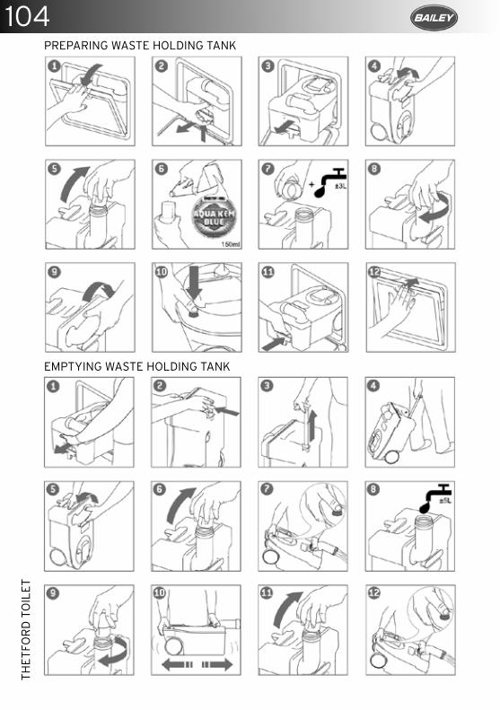
104TH
ETFO
RD
TO
ILET
PREPARING WASTE HOLDING TANK
EMPTYING WASTE HOLDING TANK
105
REF
RIG
ERA
TOR
S
REFRIGERATOR OPERATION
The refrigerator is equipped to operate on three power modes:
• Mains voltage (230v AC)• Direct-current voltage (12v DC)• Gas (liquid gas propane/butane).
When the appliance is first put into operation, there may be a mild odour which will disappear after a few hours.Park the vehicle level, particularly when starting up the refrigerator and filling with food before starting a journey.The cooling unit is silent in operation.The refrigerator will take several hours to reach its operating temperature in the coo-ling compartment. The freezer compartment should be cold about one hour after switching on the refrigerator.
CLEANING
Before starting up the refrigerator it is recommended that you clean it inside and repeat this at regular intervals. Use a soft cloth and lukewarm water with a mild detergent. Always dry thoroughly. Keep the condensation water drain channel free of deposits.To avoid material alterations, do not use soap or hard, abrasive or soda-based cleaning agents. Do not allow the door seal to come into contact with oil or grease.
MAINTENANCE
In compliance with the applicable regulations, please note that the gas unit and the connected ventilation ducts must be checked by authorised technical personnel after first use and after every other year for compliance with the European Standard EN 1949. A test certificate has to be issued. It is the user’s responsibility to arrange this test.The gas burner must be inspected and cleaned as necessary at least once a year. When using liquefied petroleum gas (tank or refill cylinders) the maintenance interval is reduced to half yearly or quarterly. Keep the evidence of maintenance work carried out on your refrigerator. Work on gas and electrical equipment shall be carried out by qualified personnel only.
DEFROSTING
As time goes by, frost builds up on the fins inside the refrigerator. A layer of frost thicker on one side may occur and does not represent a malfunction. When this layer of frost is about 3 mm thick, the refrigerator should be defrosted.
1. Switch off the refrigerator, as described in section Shutting off the refrigerator.
2. Remove all food and the ice cube tray.3. Leave the refrigerator door open to allow
air to enter and to prevent formation of mildew.
4. After defrosting (freezer compartment and fins free of frost) wipe both cooling compartments dry with a cloth.
Water thawing in the main compartment of the refrigerator runs into an appropriate container at the back of the refrigerator. From there, the water evaporates.
ENVIRONMENTAL NOTICES
Ammonia (a natural compound of hydrogen and nitrogen) is used in the cooling unit as a coolant. Non-ozone-hazardous cyclopentane is used as a propellant for manufacturing PU foam insulation.
Do not dispose of batteries in domestic waste. Take your used batteries to a collection point.
ENERGY SAVING TIPS
• At an average ambient temperature of 25°C, it is sufficient to operate the refrigerator at middle thermostat setting. Where possible, always store pre-cooled products.
• Do not expose the refrigerator to direct sunlight or any other heat source (e.g. heater).
• Ensure that air circulation of the refrigeration unit is not obstructed.
• Arrange the shelves evenly in the refrigerator (in the cooling compartment) in order to achieve the most efficient use of energy. Do not overfill the storage grids and compartments to prevent obstructing the internal air circulation.
• Maintain a clearance of approx. 10 mm between chilled products and post-evaporator ‘cooling fins’.
106R
EFR
IGER
ATO
RS
• Defrosting at regular intervals saves energy (see section Defrosting).
• Open the refrigerator door only for a short period of time when removing products.
• Run the refrigerator for about 12 hours before filling it.
DECLARATION OF CONFORMITY
The current Declaration of Conformity can also be requested directly from Dometic GmbH,Siegen.
SAFETY INSTRUCTIONS
APPLICATION ACCORDING TO REGULATIONS
This refrigerator is designed for installation in recreation vehicles such as caravans. The refrigerator is to be used solely for storing foodstuffs.
The refrigerator is not suitable for the proper storage of medication. Please observe in addition the instructions in the medication package inserts.
USERS RESPONSIBILITY
Anyone operating the refrigerator must be familiar with the safe handling and understand the advice in these operating instructions.
This appliance is not intended for use by persons (including children) with reduced physical, sensory or mental capabilities, or lack of experience and knowledge, unless they are supervised or have been given instruction concerning use of the appliance by a person responsible for their safety. Children should be supervised to ensure that they do not play with the appliance. Cleaning and user maintenance shall not be completed by children.
WORKING UPON AND CHECKING THE REFRIGERATOR
Work on gas equipment, exhaust system and electrical facilities must be carried out by authorised personnel only. Substantial damage to property and/or injury to persons can arise through unprofessional procedures.
Never use an unshielded flame to check gas bearing parts and pipes for leakage. The is a danger of fire or explosion.
Never open the absorber cooling unit. It is under high pressure. There is a danger of injury.
INFORMATION ON COOLANT
Ammonia is used as a coolant. This is a natural compound also used in household cleaning agents (1 litre of Salmiak cleaner contains up to 200g of ammonia, about twice as much as used in the refrigerator). Sodium chromate is used for corrosion protection (1.8% by weight of the solvent).
In the event of leakage (easily identifiable from the strong odour), proceed as follows:
• Switch off the appliance.• Air the room thoroughly.• Inform authorised customer services.
For your safety it was ascertained in an expert’s report that no impairment of health exists when the coolant is discharged.
APPLIANCES WITH ELECTRONICS (MES/AES)Car manufacturers often use a battery management system, which provides the caravan with constant voltage in trailer mode.If the car and trailer remain parked for more than 30 minutes with the engine switched off, the battery management system automatically switches off the permanent positive supply to the caravan (to prevent the battery from discharging). Fridges with control electronics (MES/AES) are then inoperative.
Check whether your drawing vehicle is equipped with a battery management system.
A permanent 12v power supply must be guaranteed for operation of the MES/AES fridges. OPERATING THE REFRIGERATOR WITH GAS
It is imperative that the operating pressure of the pressure reducer on the gas system corresponds to the data specified on the rating plate of the refrigerator. Compare the operating pressure of the rating plate with the data specified on the pressure reducing valve of the liquid gas cylinder.
Dometic refrigerators are equipped for a connection pressure of 30mbar.
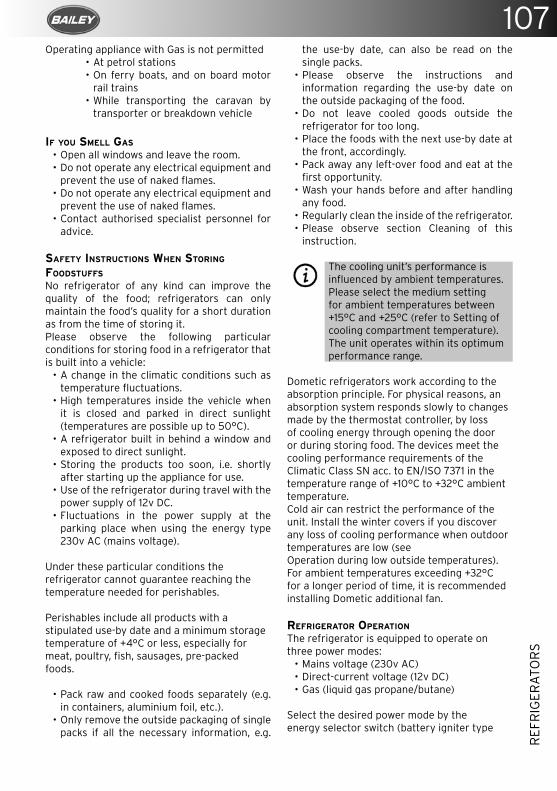
107
REF
RIG
ERA
TOR
S
Operating appliance with Gas is not permitted• At petrol stations• On ferry boats, and on board motor
rail trains• While transporting the caravan by
transporter or breakdown vehicle
IF YOU SMELL GAS
• Open all windows and leave the room.• Do not operate any electrical equipment and
prevent the use of naked flames.• Do not operate any electrical equipment and
prevent the use of naked flames.• Contact authorised specialist personnel for
advice.
SAFETY INSTRUCTIONS WHEN STORING FOODSTUFFS
No refrigerator of any kind can improve the quality of the food; refrigerators can only maintain the food’s quality for a short duration as from the time of storing it.Please observe the following particular conditions for storing food in a refrigerator that is built into a vehicle:
• A change in the climatic conditions such as temperature fluctuations.
• High temperatures inside the vehicle when it is closed and parked in direct sunlight (temperatures are possible up to 50°C).
• A refrigerator built in behind a window and exposed to direct sunlight.
• Storing the products too soon, i.e. shortly after starting up the appliance for use.
• Use of the refrigerator during travel with the power supply of 12v DC.
• Fluctuations in the power supply at the parking place when using the energy type 230v AC (mains voltage).
Under these particular conditions the refrigerator cannot guarantee reaching the temperature needed for perishables.
Perishables include all products with a stipulated use-by date and a minimum storage temperature of +4°C or less, especially for meat, poultry, fish, sausages, pre-packed foods.
• Pack raw and cooked foods separately (e.g. in containers, aluminium foil, etc.).
• Only remove the outside packaging of single packs if all the necessary information, e.g.
the use-by date, can also be read on the single packs.
• Please observe the instructions and information regarding the use-by date on the outside packaging of the food.
• Do not leave cooled goods outside the refrigerator for too long.
• Place the foods with the next use-by date at the front, accordingly.
• Pack away any left-over food and eat at the first opportunity.
• Wash your hands before and after handling any food.
• Regularly clean the inside of the refrigerator.• Please observe section Cleaning of this
instruction.
The cooling unit’s performance is influenced by ambient temperatures. Please select the medium setting for ambient temperatures between +15°C and +25°C (refer to Setting of cooling compartment temperature). The unit operates within its optimum performance range.
Dometic refrigerators work according to the absorption principle. For physical reasons, an absorption system responds slowly to changes made by the thermostat controller, by loss of cooling energy through opening the door or during storing food. The devices meet the cooling performance requirements of theClimatic Class SN acc. to EN/ISO 7371 in the temperature range of +10°C to +32°C ambient temperature.Cold air can restrict the performance of the unit. Install the winter covers if you discover any loss of cooling performance when outdoor temperatures are low (seeOperation during low outside temperatures).For ambient temperatures exceeding +32°C for a longer period of time, it is recommended installing Dometic additional fan.
REFRIGERATOR OPERATION
The refrigerator is equipped to operate on three power modes:
• Mains voltage (230v AC)• Direct-current voltage (12v DC)• Gas (liquid gas propane/butane)
Select the desired power mode by the energy selector switch (battery igniter type
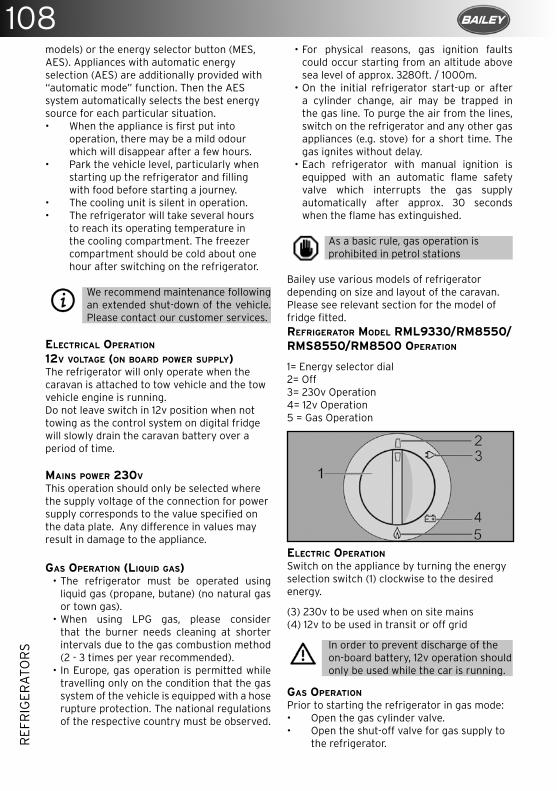
108R
EFR
IGER
ATO
RS
models) or the energy selector button (MES, AES). Appliances with automatic energy selection (AES) are additionally provided with “automatic mode” function. Then the AES system automatically selects the best energy source for each particular situation.• When the appliance is first put into
operation, there may be a mild odour which will disappear after a few hours.
• Park the vehicle level, particularly when starting up the refrigerator and filling with food before starting a journey.
• The cooling unit is silent in operation.• The refrigerator will take several hours
to reach its operating temperature in the cooling compartment. The freezer compartment should be cold about one hour after switching on the refrigerator.
We recommend maintenance following an extended shut-down of the vehicle. Please contact our customer services.
ELECTRICAL OPERATION
12V VOLTAGE (ON BOARD POWER SUPPLY)The refrigerator will only operate when the caravan is attached to tow vehicle and the tow vehicle engine is running. Do not leave switch in 12v position when not towing as the control system on digital fridge will slowly drain the caravan battery over a period of time. MAINS POWER 230V
This operation should only be selected where the supply voltage of the connection for power supply corresponds to the value specified on the data plate. Any difference in values may result in damage to the appliance.
GAS OPERATION (LIQUID GAS) • The refrigerator must be operated using
liquid gas (propane, butane) (no natural gas or town gas).
• When using LPG gas, please consider that the burner needs cleaning at shorter intervals due to the gas combustion method (2 - 3 times per year recommended).
• In Europe, gas operation is permitted while travelling only on the condition that the gas system of the vehicle is equipped with a hose rupture protection. The national regulations of the respective country must be observed.
• For physical reasons, gas ignition faults could occur starting from an altitude above sea level of approx. 3280ft. / 1000m.
• On the initial refrigerator start-up or after a cylinder change, air may be trapped in the gas line. To purge the air from the lines, switch on the refrigerator and any other gas appliances (e.g. stove) for a short time. The gas ignites without delay.
• Each refrigerator with manual ignition is equipped with an automatic flame safety valve which interrupts the gas supply automatically after approx. 30 seconds when the flame has extinguished.
As a basic rule, gas operation is prohibited in petrol stations
Bailey use various models of refrigerator depending on size and layout of the caravan. Please see relevant section for the model of fridge fitted.REFRIGERATOR MODEL RML9330/RM8550/RMS8550/RM8500 OPERATION
1= Energy selector dial2= Off3= 230v Operation4= 12v Operation5 = Gas Operation
ELECTRIC OPERATION
Switch on the appliance by turning the energy selection switch (1) clockwise to the desired energy.
(3) 230v to be used when on site mains(4) 12v to be used in transit or off grid
In order to prevent discharge of the on-board battery, 12v operation should only be used while the car is running.
GAS OPERATION
Prior to starting the refrigerator in gas mode:• Open the gas cylinder valve.• Open the shut-off valve for gas supply to
the refrigerator.
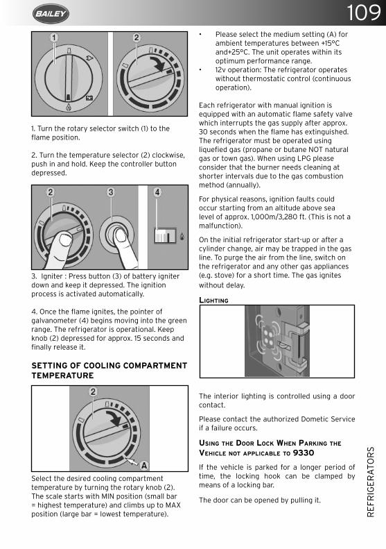
109
REF
RIG
ERA
TOR
S
1. Turn the rotary selector switch (1) to the flame position.
2. Turn the temperature selector (2) clockwise, push in and hold. Keep the controller button depressed.
3. Igniter : Press button (3) of battery igniter down and keep it depressed. The ignition process is activated automatically.
4. Once the flame ignites, the pointer of galvanometer (4) begins moving into the green range. The refrigerator is operational. Keep knob (2) depressed for approx. 15 seconds and finally release it.
SETTING OF COOLING COMPARTMENT TEMPERATURE
Select the desired cooling compartment temperature by turning the rotary knob (2).The scale starts with MIN position (small bar = highest temperature) and climbs up to MAX position (large bar = lowest temperature).
• Please select the medium setting (A) for ambient temperatures between +15°C and+25°C. The unit operates within its optimum performance range.
• 12v operation: The refrigerator operates without thermostatic control (continuous operation).
Each refrigerator with manual ignition is equipped with an automatic flame safety valve which interrupts the gas supply after approx. 30 seconds when the flame has extinguished. The refrigerator must be operated using liquefied gas (propane or butane NOT natural gas or town gas). When using LPG please consider that the burner needs cleaning at shorter intervals due to the gas combustion method (annually).
For physical reasons, ignition faults could occur starting from an altitude above sea level of approx. 1,000m/3,280 ft. (This is not a malfunction).
On the initial refrigerator start-up or after a cylinder change, air may be trapped in the gas line. To purge the air from the line, switch on the refrigerator and any other gas appliances (e.g. stove) for a short time. The gas ignites without delay.
LIGHTING
The interior lighting is controlled using a door contact.
Please contact the authorized Dometic Service if a failure occurs.
USING THE DOOR LOCK WHEN PARKING THE VEHICLE NOT APPLICABLE TO 9330
If the vehicle is parked for a longer period of time, the locking hook can be clamped by means of a locking bar.
The door can be opened by pulling it.
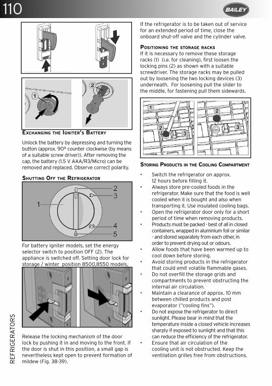
110R
EFR
IGER
ATO
RS
If the refrigerator is to be taken out of service for an extended period of time, close the onboard shut-off valve and the cylinder valve.
POSITIONING THE STORAGE RACKS
If it is necessary to remove these storage racks (1) (i.e. for cleaning), first loosen the locking pins (2) as shown with a suitable screwdriver. The storage racks may be pulled out by loosening the two locking devices (3) underneath. For loosening pull the slider to the middle, for fastening pull them sidewards.
STORING PRODUCTS IN THE COOLING COMPARTMENT
• Switch the refrigerator on approx. 12 hours before filling it.
• Always store pre-cooled foods in the refrigerator. Make sure that the food is well cooled when it is bought and also when transporting it. Use insulated cooling bags.
• Open the refrigerator door only for a short period of time when removing products.
• Products must be packed - best of all in closed containers, wrapped in aluminium foil or similar - and stored separately from each other, in order to prevent drying out or odours.
• Allow foods that have been warmed up to cool down before storing.
• Avoid storing products in the refrigerator that could emit volatile flammable gases.
• Do not overfill the storage grids and compartments to prevent obstructing the internal air circulation.
• Maintain a clearance of approx. 10 mm between chilled products and post evaporator (“cooling fins”).
• Do not expose the refrigerator to direct sunlight. Please bear in mind that the temperature inside a closed vehicle increases sharply if exposed to sunlight and that this can reduce the efficiency of the refrigerator.
• Ensure that air circulation of the cooling unit is not obstructed. Keep the ventilation grilles free from obstructions.
EXCHANGING THE IGNITER’S BATTERY
Unlock the battery by depressing and turning the button (approx. 90° counter clockwise (by means of a suitable screw driver)). After removing the cap, the battery (1.5 V AAA/R3/Micro) can be removed and replaced. Observe correct polarity.
SHUTTING OFF THE REFRIGERATOR
For battery igniter models, set the energy selector switch to position OFF (2). The appliance is switched off. Setting door lock for storage / winter position 8500,8550 models,
Release the locking mechanism of the door lock by pushing it in and moving to the front. If the door is shut in this position, a small gap is nevertheless kept open to prevent formation of mildew (Fig. 38-39).
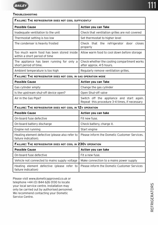
111
REF
RIG
ERA
TOR
S
FAILURE: THE REFRIGERATOR DOES NOT COOL SUFFICIENTLY
Possible Cause Action you can Take
Inadequate ventilation to the unit Check that ventilation grilles are not covered
Thermostat setting is too low Set thermostat to higher level
The condenser is heavily frosted Check that the refrigerator door closes properly
Too much warm food has been stored inside within a short period of time
Allow warm food to cool down before storage
The appliance has been running for only a short period of time.
Check whether the cooling compartment works after approx. 4-5 hours.
Ambient temperature is too high Regularly remove ventilation grilles.
FAILURE: THE REFRIGERATOR DOES NOT COOL IN GAS OPERATION MODE
Possible Cause Action you can Take
Gas cylinder empty Change the gas cylinder
Is the upstream shut-off device open? Open Shut-off valve
Air in the Gas Pipe? Switch off the appliance and start again. Repeat this procedure 3-4 times, if necessary
FAILURE: THE REFRIGERATOR DOES NOT COOL IN 12V OPERATION
Possible Cause Action you can take
On-board fuse defective Fit new fuse.
On-board battery discharge Check battery, charge it.
Engine not running Start engine
Heating element defective (please also refer to failure indication).
Please inform the Dometic Customer Services.
FAILURE: THE REFRIGERATOR DOES NOT COOL IN 230V OPERATION
Possible Cause Action you can take
On-board fuse defective Fit a new fuse.
Vehicle not connected to mains supply voltage Make connection to a mains power supply
Heating element defective (please refer to failure indication)
Please inform the Dometic Customer Services
TROUBLESHOOTING
Please visit www.dometicapproved.co.uk or telephone +44 (0) 844 626 0130 to locate your local service centre. Installation may only be carried out by authorised personnel. We recommend contacting your Dometic Service Centre.
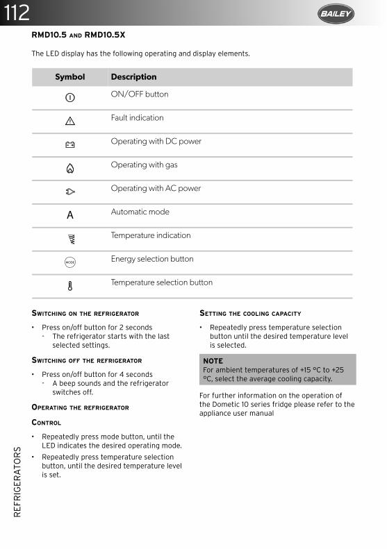
112R
EFR
IGER
ATO
RS
RMD10.5 AND RMD10.5X
SWITCHING ON THE REFRIGERATOR
• Press on/off button for 2 seconds- The refrigerator starts with the last
selected settings.
SWITCHING OFF THE REFRIGERATOR
• Press on/off button for 4 seconds- A beep sounds and the refrigerator
switches off.
OPERATING THE REFRIGERATOR
CONTROL
• Repeatedly press mode button, until the LED indicates the desired operating mode.
• Repeatedly press temperature selection button, until the desired temperature level is set.
SETTING THE COOLING CAPACITY
• Repeatedly press temperature selection button until the desired temperature level is selected.
NOTEFor ambient temperatures of +15 °C to +25 °C, select the average cooling capacity.
For further information on the operation of the Dometic 10 series fridge please refer to the appliance user manual
The LED display has the following operating and display elements.
EN
Using the refrigerator RMD10
16
RMD10.5 and RMD10.5X
The LED display has the following operating and display elements (fig. 1 B, page 3):
5 Using the refrigerator
I
Symbol Description
ON/OFF button
Fault indication
Operating with DC power
Operating with gas
Operating with AC power
Automatic mode
Temperature indication
Energy selection button
Temperature selection button
NOTE • Before starting your new refrigerator for the first time, clean it inside
and outside with a damp cloth for hygienic reasons.• When using the refrigerator for the first time, there may be a mild
odor which will disappear after a few hours. Air the living space well.• Park the vehicle so that it is level, especially when starting up and fill-
ing the refrigerator before setting off on a journey.• The cooling performance can be affected by:
– the ambient temperature (e.g. when the vehicle is exposed to direct sunlight)
– the amount of food to be refrigerated– how often you open the door
A
MODE
RMD10-O-WEST.book Seite 16 Sonntag, 27. Januar 2019 7:05 07
113
SMO
KE
ALA
RM
STAINLESS STEEL SINK
Stainless steel sinks need little maintenance other than cleaning immediately after use.
Most deposits can be removed by washing with soap or mild detergent and hot water, followed by a clean water rinse and drying with a soft cloth to prevent water spotting.
For more tenacious deposits a non-abrasive multi-purpose cream cleaner such as CIF should be used, followed by a clean water rinse and drying.
Tannin stains can be removed by a solution of washing soda and water applied with a soft cloth/sponge followed by a clean water rinse to remove any residues, and drying with a soft cloth.
When cleaning with anything other than water be careful not to get the solution onto your kitchen worktop.
Always avoid bleach and trigger-dispense products and never use wire wool or leave wet cloths, pads or containers on the surface as they may form water marks.
Toilet Compartment Sink
OPAQUE FINISH
For the usual daily cleaning of the opaque sink, use a scrub sponge such as Scotch-Brite with a powder abrasive detergent (for example, scouring powder).1. Rinse with water.2. Use a microfibre cloth to wipe.
GLOSSY FINISH
For the usual daily cleaning of the glossy sink, use a damp cloth or sponge with liquid soap, which does not contain abrasive particles.1. Rinse with water.2. Use a microfibre cloth to wipe.
Do not use abrasive detergents, alcohol, acetone or solvents, because they will damage the material. In case of accidental contact with such solvents, quickly rinse with water.


116SO
FT F
UR
NIS
HIN
GS
SOFT FURNISHINGS
CARPET
When cleaning the interior of your caravan please remove the carpet from the vehicle. Vacuum the carpets to take the dirt out of the pile.
For general cleaning use a dry shampoo, following the product’s directions.
Never put the carpet in a washing machine or a tumble dryer.
UPHOLSTERY CLEANING AND CARE
The care guide is to help you care for your upholstery and maintain the product for many years.
You many find your upholstery a little firm at least to begin with, this is perfectly normal as all foam and filling composites will naturally soften in time. This softening does not constitute as a fault under the warranty.
Fabrics with a pile may appear to have a difference in shades, this is due to the direction of the pile and how the light reflects. This is not a fault, it’s part of the charm of the fabrics. Regular care with a soft brush will ease the pile back and reduce the effect of the pile being flattened over time.
Fabric will stretch, move and develop creases/wrinkles during use, these are expected and are completely normal during the lifetime of the product.
Most fabrics will show signs of wear over time this is due to friction, another sign of use can be little balls of fuzz which could appear on the fabric surface, this can be different for each fabric as each fabric will be made up of different yarns and weaves, all these are signs of normal use of the product and occur naturally and is not considered a defect.
It is important all cushions/upholstery are regularly “Dressed”, this is achieved by a good plumping of the cushions/upholstery to ensure the cushions revert to their shape. All cushions and arm pads should have the creases and wrinkles smoothed out daily. Without “Dressing” and “Smoothing” the cushions it could give the appearance of flat/miss shaped or making the fabric appear loose or baggy. This is not a defect but part of the care of the product/s.
Please ensure all cushions/upholstery are always placed in the correct position during use.
Vacuuming or using a soft brush frequently on products helps to eliminate dirt and dust particles which will also keep the product in tip-top condition.
Avoiding prolonged exposure in direct sunlight or heat source as this will have an adverse effect on the product/s.
Dry clean all products only, if a spillage occurs, we advise removing the excess with a soft absorbent cloth or paper towel. Do not soak or rub/scrub any fabrics, we always advise contacting a professional cleaning services for advice
WINTERISATION AND STORAGE
Mattresses are made from fire retardant fabric and are of a honeycomb constriction based on solid foam with diamond cut out to perform like a spring. It is recommended that mattresses be stored on edge during winter. Try to keep your cushions away from direct sunlight. CURTAINS
It is recommended that the curtains in your caravan are washed on a delicate cycle at 30°C. This will not damage the clip glides. Shrinkage may be caused should you decide to dry clean your curtains.
Curtains should not be left closed during daytime hours otherwise some fading may occur.
WINDOW BLINDS
PLEATED WINDOW BLINDS
Please note the blinds should not be closed (down position) when the vehicle is travelling or when in storage for prolonged periods.
The sun screen is housed at the bottom and the fly screen at the top of the blind. To open hold the cross bar and pull up or down. Both blinds can be fully extended to totally cover the window or can meet at any position to give sun shading/privacy and protection from insects entering the vehicle.The blinds are pre-set to the correct tension.If re-tensioning is required please follow these steps:
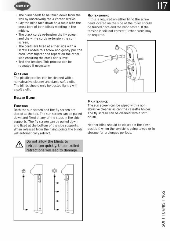
117
SOFT
FU
RN
ISH
ING
S
• The blind needs to be taken down from the wall by unscrewing the 4 corner screws.
• Lay the blind face down on a table with the cross bars of both blinds meeting in the middle.
• The black cords re-tension the fly screen and the white cords re-tension the sun screen.
• The cords are fixed at either side with a screw. Loosen this screw and gently pull the cord 5mm tighter and repeat on the other side ensuring the cross bar is level.
• Test the tension. This process can be repeated if necessary.
CLEANING
The plastic profiles can be cleaned with a non-abrasive cleaner and damp soft cloth. The blinds should only be dusted lightly with a soft cloth.
ROLLER BLIND
FUNCTION
Both the sun screen and the fly screen are stored at the top. The sun screen can be pulled down and fixed at any of the stops in the side supports. The fly screen can be pulled down and fixed at the bottom of the side supports. When released from the fixing points the blinds will automatically retract.
Do not allow the blinds to retract too quickly. Uncontrolled retractions will lead to damage
RE-TENSIONING
If this is required on either blind the screw head located on the side of the roller should be turned once and the blind tested. If the tension is still not correct further turns may be required.
MAINTENANCE
The sun screen can be wiped with a non-abrasive cleaner as can the cassette holder. The fly screen can be cleaned with a soft brush.
Neither blind should be closed (in the down position) when the vehicle is being towed or in storage for prolonged periods.
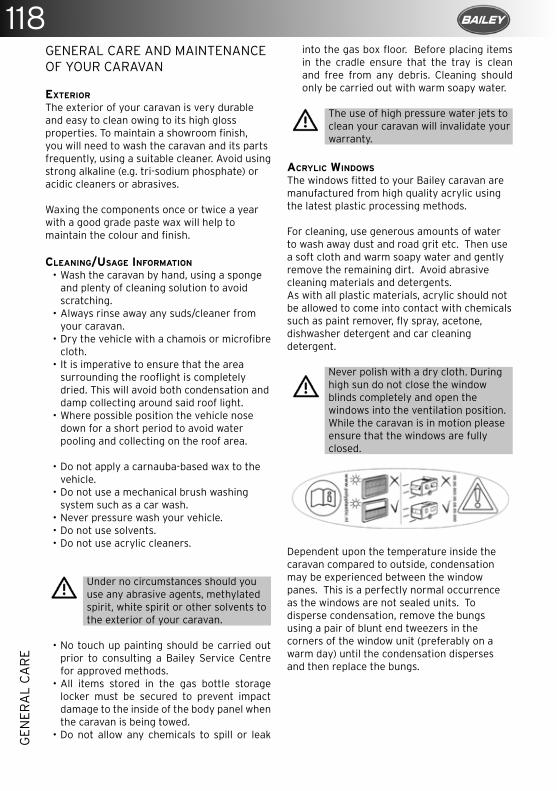
118G
ENER
AL
CA
RE
GENERAL CARE AND MAINTENANCE OF YOUR CARAVAN
EXTERIOR
The exterior of your caravan is very durable and easy to clean owing to its high gloss properties. To maintain a showroom finish, you will need to wash the caravan and its parts frequently, using a suitable cleaner. Avoid using strong alkaline (e.g. tri-sodium phosphate) or acidic cleaners or abrasives.
Waxing the components once or twice a year with a good grade paste wax will help to maintain the colour and finish.
CLEANING/USAGE INFORMATION
• Wash the caravan by hand, using a sponge and plenty of cleaning solution to avoid scratching.
• Always rinse away any suds/cleaner from your caravan.
• Dry the vehicle with a chamois or microfibre cloth.
• It is imperative to ensure that the area surrounding the rooflight is completely dried. This will avoid both condensation and damp collecting around said roof light.
• Where possible position the vehicle nose down for a short period to avoid water pooling and collecting on the roof area.
• Do not apply a carnauba-based wax to the vehicle.
• Do not use a mechanical brush washing system such as a car wash.
• Never pressure wash your vehicle.• Do not use solvents.• Do not use acrylic cleaners.
Under no circumstances should you use any abrasive agents, methylated spirit, white spirit or other solvents to the exterior of your caravan.
• No touch up painting should be carried out prior to consulting a Bailey Service Centre for approved methods.
• All items stored in the gas bottle storage locker must be secured to prevent impact damage to the inside of the body panel when the caravan is being towed.
• Do not allow any chemicals to spill or leak
into the gas box floor. Before placing items in the cradle ensure that the tray is clean and free from any debris. Cleaning should only be carried out with warm soapy water.
The use of high pressure water jets to clean your caravan will invalidate your warranty.
ACRYLIC WINDOWS
The windows fitted to your Bailey caravan are manufactured from high quality acrylic using the latest plastic processing methods.
For cleaning, use generous amounts of water to wash away dust and road grit etc. Then use a soft cloth and warm soapy water and gently remove the remaining dirt. Avoid abrasive cleaning materials and detergents.As with all plastic materials, acrylic should not be allowed to come into contact with chemicals such as paint remover, fly spray, acetone, dishwasher detergent and car cleaning detergent.
Never polish with a dry cloth. During high sun do not close the window blinds completely and open the windows into the ventilation position. While the caravan is in motion please ensure that the windows are fully closed.
Dependent upon the temperature inside the caravan compared to outside, condensation may be experienced between the window panes. This is a perfectly normal occurrence as the windows are not sealed units. To disperse condensation, remove the bungs using a pair of blunt end tweezers in the corners of the window unit (preferably on a warm day) until the condensation disperses and then replace the bungs.
119
GEN
ERA
L C
AR
E
WINDOW CATCHES AND STAYS
OPENING
• Turn catch arm to the vertical position to open.
• A night vent position is available by depressing the locking knob and locating the catch into the middle catch plate slot.
• The windows are held open by an adjustable arm. Tightening the knob in a clockwise direction will hold the window open in the desired position.
Always ensure the knob is unscrewed before closing the window. Failure to do so may cause damage to the window stay arm. Always ensure that windows are fully closed during wet weather and not on night vent settings.
HUMIDITY
Air contains moisture.The higher the temperature of the air the more water it is able to hold. Air at 20°C can hold a lot more moisture than air at 10°C. The term “relative humidity” describes the amount moisture air contains at a given temperature. 100% relative humidity means the air is holding as much moisture as possible at the current temperature.
The more humid the air in your caravan, the more energy it takes to heat because the water in the air is also being heated.
A good range of indoor humidity for comfort and health is between 30% and 60% during cooler months of the year. Mould is likely to occur if the relative humidity indoors is 70% or more for long periods of time. Keeping humidity levels under 50% also helps to minimise or control dust mites.
CONDENSATION
Water vapour condenses on cold surfaces when the humidity is high inside the van but it is cold outside.
Possible causes of condensation• Lack of adequate heating or ventilation.• Water ingress from the outside through
leakage, seepage or open windows.• High levels of moisture/water vapour
being produced inside the caravan.
Humid air and condensation can also be generated by things people do on a daily basis.• Cooking: up to 3 litres per day.• Showers: 1.5 litres per person.• Washing dishes: up to 1 litres per day.• Breathing: active adult 0.2 litres an hour.• Breathing, adult asleep: 0.02 litres an
hour.
HOW TO KEEP YOUR CARAVAN DRY AND AVOID CONDENSATION
There are lots of things you can do to minimise dampness and condensation in your caravan.
The key actions:• Provide ventilation and/or reduce relative
humidity of air, particularly in moisture prone periods of year.
• When the moisture is produced in the van (cooking, shower).
• Increase heating to raise the temperature of the air and the cold surfaces.
• On dry days open windows to allow humid air to ventilate out of the van. It is better to open a few windows a little throughout the whole caravan. This helps the air to move through the caravan.
• One window open wide may not be as effective.
• Try to do this as often as possible (at least once a week), but keep windows closed on wet days as damp air may increase indoor humidity.
FURNITURE
Moisture in the air can cause damage to furniture as the wood expands or contracts with an increase or decrease in the relative humidity. A relative humidity of between 40% and 60% is tolerable. If values are maintained outside this range for a sustained period damage to the furniture may occur. The damage can be visible if the relative humidity is higher than 80% for a long time. To prevent damage, ventilate the van, using dehumidifiers or water absorbent substances.When wood is wet, wipe it dry. Do not just wait for the sun to dry it. The longer the water stays on the surface, the more damage it can do.Defects caused by high temperature or high relative humidity of air will not be covered by your warranty.
120G
ENER
AL
CA
RE
WINTERIZATION & STORAGE
The following applies whenever your caravan is stored, particularly during winter months. If you do not intend on using your vehicle for a while it is an ideal time to arrange for your caravan to have its annual service at your appointed dealer.
• It is a good idea to store the caravan with the nose down; this will avoid any water pooling on the roof.
• Do not leave your vehicle near trees or latch-type gates due to possible wind damage.
• Keep any grass around the floor of the caravan short to maintain airflow and stop any possible damp getting into it.
• It is advised that the caravan is ventilated regularly throughout the storage period, opening windows, doors and rooflights where possible.
• All moving parts should be checked for free operation.
• Clean all cooking appliances and the refrigerator before parking up the vehicle.
• Charge up the on-board battery every 2 months.
• Leave the refrigerator door open. • Leave the furniture and locker doors open
to allow air to circulate fully.• Ensure that the entire water system is
thoroughly drained.• Make sure that all plumbing pipes, drains,
and water supply appliances within the caravan are properly drained.
• Remove the battery from the caravan to keep it warmer. If the battery cells were to freeze this could cause damage to the cells and decrease the life of the battery.
• Try to cover as much as possible of the underside of the caravan to prevent snow from collecting. This will help to prevent damage to the tyres due to weather conditions.
• Apply a lubricant to all locks; this will prevent freezing.
MODIFICATIONS & DIY WORK
Owners need to be aware that carrying out DIY modifications to your caravan may, in certain circumstances, invalidate the warranty cover and could also affect the safety and structure of the vehicle.
CARAVAN KEYS
Each caravan is supplied with 2 identical keys. In the event of both keys being lost these cannot be replaced. In this instance a new lock will have to be fitted with a fresh set of keys.
SPARES & AFTERSALES
There are numerous parts and accessories available for your caravan either from your Bailey retailer or through the Bailey Parts website. You are more than welcome to contact the parts website for anything you may require. However, if it is a safety or warranty-critical item you will need to obtain it from your Bailey retailer who will fit the component for you.
www.primaleisure.com
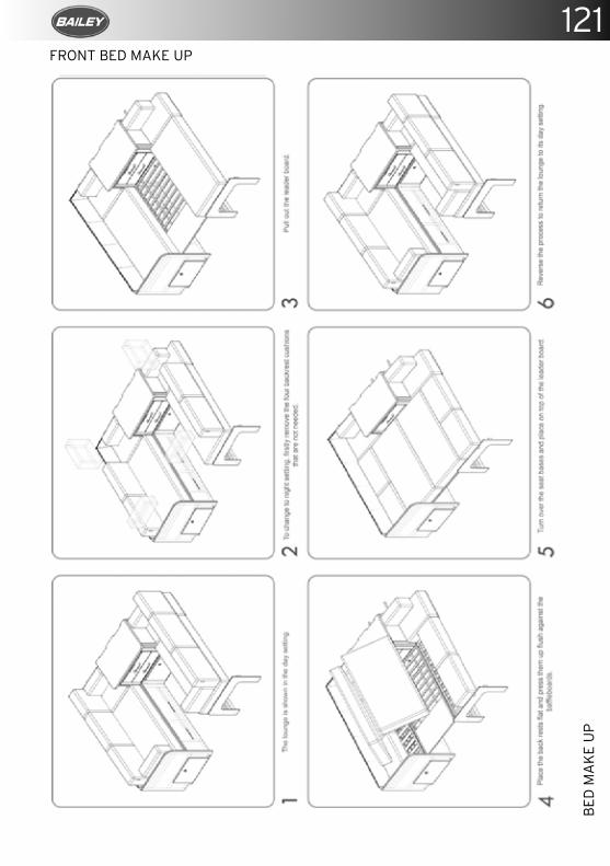
121
BED
MA
KE
UP
FRONT BED MAKE UP
122B
ED M
AK
E U
P
FRONT BED MAKE UP
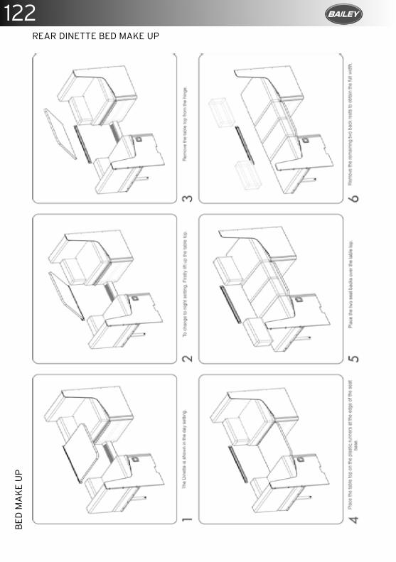
122B
ED M
AK
E U
P124
BED
MA
KE
UP
REAR DINETTE BED MAKE UPREAR DINETTE BED MAKE UP
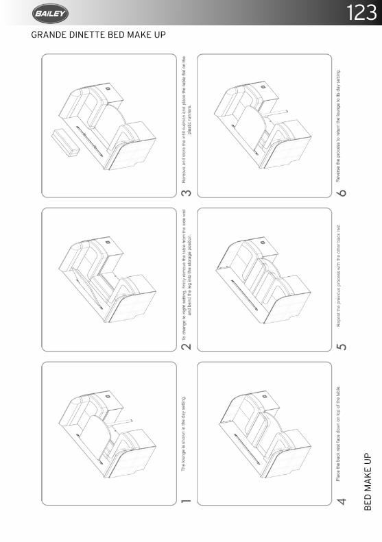
123
BED
MA
KE
UP
GRANDE DINETTE BED MAKE UP
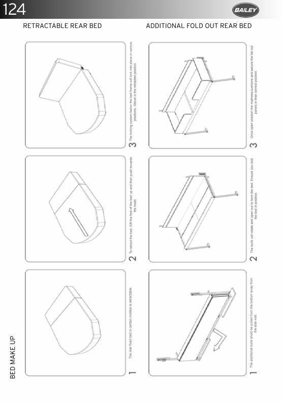
124B
ED M
AK
E U
P
RETRACTABLE REAR BED ADDITIONAL FOLD OUT REAR BED
126B
ED M
AK
E U
P
RETRACTABLE REAR BED ADDITIONAL FOLD OUT REAR BED
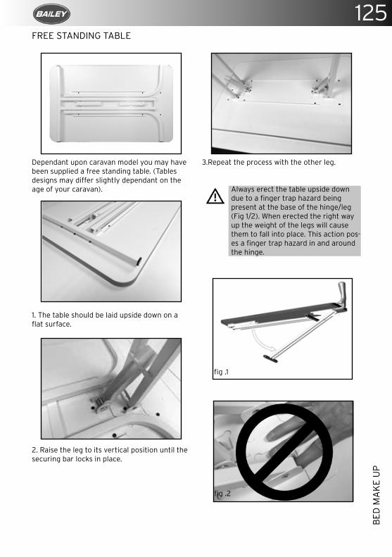
125
BED
MA
KE
UP
152
FITT
ED F
UR
NIT
UR
E C
ON
FIG
UR
ATI
ON
S
FREE STANDING TABLE
Dependant upon caravan model you may have been supplied a free standing table. (Tables designs may differ slightly dependant on the age of your caravan).
1. The table should be laid upside down on a flat surface.
2. Raise the leg to its vertical position until the securing bar locks in place.
3.Repeat the process with the other leg.
Always erect the table upside down due to a finger trap hazard being present at the base of the hinge/leg (Fig 1/2). When erected the right way up the weight of the legs will cause them to fall into place. This action pos-es a finger trap hazard in and around the hinge.
FREE STANDING TABLE
Dependant upon caravan model you may have been supplied a free standing table. (Tables designs may differ slightly dependant on the age of your caravan).
1. The table should be laid upside down on a flat surface.
2. Raise the leg to its vertical position until the securing bar locks in place.
fig .1
fig .2
126
BED
MA
KE
UP
RETRACTABLE REAR BED ADDITIONAL FOLD OUT REAR BED

126
©BAILEY OF BRISTOL 2018. ALL RIGHTS RESERVEDNo part of this document may be reproduced or transmitted in any form or by any means, electronic or mechanical, for any purpose, without the express permission of Bailey of Bristol Ltd.
BED
MA
KE
UP

127

Banner-A5-Bailey-2018-Ad.indd 1 31/08/2018 12:02
CARAVA
N O
WN
ERS MA
NU
AL
CARAVA
N O
WN
ERS MA
NU
AL
Looking for more inform
ation?Find everything you need to know
at
www.baileyofbristol.co.uk
Connect with us!
We’d love to hear from
you!
36
TH
E S
ER
VIC
E M
AN
UA
L
PAGE LEFT BLANK INTENTIONALLY
26

37T
HE
SE
RV
ICE
MA
NU
AL
If the caravan is sold before the end of the original warranty the remaining period can be transferred to the new owner using the warranty transfer form. There is a fee charged for this service of £35 including VAT.Please send a copy of the Service Handbook, Proof of the purchase date along with this sheet and a copy of the service sheets from this service guide along with a cheque for £35 to Bailey of Bristol, South Liberty Lane, Bristol, BS3 2SS. Please make your cheque payable to “Bailey Caravans Ltd”. We are unable to accept any other form of payment.In order for the warranty to remain valid the caravan must have been serviced annually by an authorised Bailey Service Centre prior to the transfer of ownership. Failure to do so will invalidate any further warranty cover.Failure to request this transfer within 3 months of acquisition by the new owner will invalidate the remaining warranty.
Terms and Conditions apply.
MODEL
VIN NUMBER
PURCHASE DATE
PREVIOUS OWNER
NEW OWNER
NEW OWNER'S ADDRESS
NEW OWNER'S TELEPHONE NUMBER
NEW OWNER'S EMAIL ADDRESS
Signed: Date:
I have read and understood the terms and conditions of the warranty, including the servicing requirements, as applicable to this vehicle.
25
26
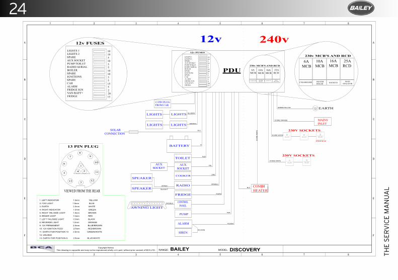
34
TH
E S
ER
VIC
E M
AN
UA
L
PAGE LEFT BLANK INTENTIONALLY
21
Copyright NoticeThis drawing is copywrite and may not be reproduced,wholly or in part, without prior consent of BCA LTD. RANGE: MODEL:
E
D
C
B
F
A
E
D
C
B
F
A
8765432
87654321
BAILEY DISCOVERY
LIGHTS 1LIGHTS 2SPAREAUX SOCKETPUMP/TOILETRADIO/AERIALBOILERSPAREIGNITIONSSPARECARALARMFRIDGE IGNVAN BATT+FRIDGE
10105105510105515522015
EARTH
13 PIN PLUGFROM CAR
BATTERY
AUXSOCKET
TOILET
LIGHTS
MAINSINLET
12v 240v
PDU
8
1
4 2
312
11
10
97
6
5
13
VIEWED FROM THE REAR
13 PIN PLUG
12v FUSES
230V SOCKETS
FRIDGE
COMBIHEATER
25ARCD
SOCKETS MAINISOLATOR
230v MCB'S AND RCD
10AMCB
16AMCB
HEATERBOILER
6AMCB
CHARGER
230v MCB'S AND RCD
230V SOCKETS
6AMCB
10AMCB
16AMCB
25ARCD
CHARGER HEATERBOILER SOCKETS MAIN
ISOLATOR
LIGHTS
LIGHTSLIGHTS
SOLARCONNECTION
AUXSOCKET
COOKER
RADIO
SPEAKER
SPEAKER
FRIDGE
CONTROLPANEL PUMP
AWNING LIGHT
1. LEFT INDICATOR 1.5mm YELLOW
2. FOG LIGHT 1.5mm BLUE
3. EARTH 2.5mm WHITE
4. RIGHT INDICATOR 1.5mm GREEN
5. RIGHT TAIL/SIDE LIGHT 1.5mm BROWN
6. BRAKE LIGHT 1.5mm RED
7. LEFT TAIL/SIDE LIGHT 1.5mm BLACK
8. REVERSE LIGHT 1.5mm ORANGE
9. 12V PERMANENT 2.5mm BLUE/BROWN
10. 12V IGNITION FEED 2.5mm RED/BROWN
11. EARTH FOR POSITION 10 2.5mm GREEN/WHITE
12. UNUSED
13. EARTH FOR POSITION 9 2.5mm BLUE/WHITE
ALARM
SIREN
12v FUSES
LIGHTS 1LIGHTS 2SPAREAUX SOCKETPUMP/TOILETRADIO/AERIALBOILERSPAREIGNITIONSSPARECARALARMFRIDGE IGNVAN BATT+FRIDGE
10105105510105515522015
BLU/BRN
GRN/BLK
BLU
R
PUR
YEL
ORG
GRN/BLUGR/BLK
BLK/WHT
R/ORG
PUR
YEL/BLK
RED/BRN
ORG/BLK
BLU
3CO
RE
WH
ITE
3CORE WHITE
3CORE WHITE
3CORE ORANGE
GREEN/YELLOW
24

35T
HE
SE
RV
ICE
MA
NU
AL
If the caravan is sold before the end of the original warranty the remaining period can be transferred to the new owner using the warranty transfer form. There is a fee charged for this service of £35 including VAT.Please send a copy of the Service Handbook, Proof of the purchase date along with this sheet and a copy of the service sheets from this service guide along with a cheque for £35 to Bailey of Bristol, South Liberty Lane, Bristol, BS3 2SS. Please make your cheque payable to “Bailey Caravans Ltd”. We are unable to accept any other form of payment.In order for the warranty to remain valid the caravan must have been serviced annually by an authorised Bailey Service Centre prior to the transfer of ownership. Failure to do so will invalidate any further warranty cover.Failure to request this transfer within 3 months of acquisition by the new owner will invalidate the remaining warranty.
Terms and Conditions apply.
MODEL
VIN NUMBER
PURCHASE DATE
PREVIOUS OWNER
NEW OWNER
NEW OWNER'S ADDRESS
NEW OWNER'S TELEPHONE NUMBER
NEW OWNER'S EMAIL ADDRESS
Signed: Date:
I have read and understood the terms and conditions of the warranty, including the servicing requirements, as applicable to this vehicle.
23
24
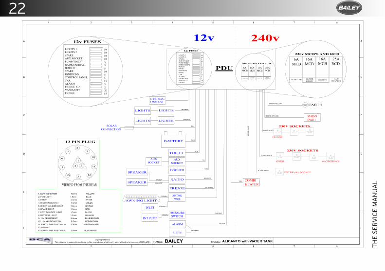
32
TH
E S
ER
VIC
E M
AN
UA
L
PAGE LEFT BLANK INTENTIONALLY
20
Copyright NoticeThis drawing is copywrite and may not be reproduced,wholly or in part, without prior consent of BCA LTD. RANGE: MODEL:
E
D
C
B
F
A
E
D
C
B
F
A
8765432
87654321
BAILEY ALICANTO with WATER TANK
LIGHTS 1LIGHTS 2SPAREAUX SOCKETPUMP/TOILETRADIO/AERIALBOILERSPAREIGNITIONSSPARECARALARMFRIDGE IGNVAN BATT+FRIDGE
10105105510105515522015
EARTH
13 PIN PLUGFROM CAR
BATTERY
AUXSOCKET
TOILET
LIGHTS
MAINSINLET
12v 240v
PDU
8
1
4 2
312
11
10
97
6
5
13
VIEWED FROM THE REAR
13 PIN PLUG
12v FUSES
230V SOCKETS
FRIDGE
COMBIHEATER
25ARCD
SOCKETS MAINISOLATOR
230v MCB'S AND RCD
16AMCB
16AMCB
HEATERBOILER
6AMCB
CHARGER
230v MCB'S AND RCD
230V SOCKETS
6AMCB
16AMCB
16AMCB
25ARCD
CHARGER HEATERBOILER SOCKETS MAIN
ISOLATOR
LIGHTS
LIGHTSLIGHTS
SOLARCONNECTION
AUXSOCKET
COOKER
RADIO
SPEAKER
SPEAKER
FRIDGE
CONTROLPANEL
PRESSURESWITCH
AWNING LIGHT
1. LEFT INDICATOR 1.5mm YELLOW
2. FOG LIGHT 1.5mm BLUE
3. EARTH 2.5mm WHITE
4. RIGHT INDICATOR 1.5mm GREEN
5. RIGHT TAIL/SIDE LIGHT 1.5mm BROWN
6. BRAKE LIGHT 1.5mm RED
7. LEFT TAIL/SIDE LIGHT 1.5mm BLACK
8. REVERSE LIGHT 1.5mm ORANGE
9. 12V PERMANENT 2.5mm BLUE/BROWN
10. 12V IGNITION FEED 2.5mm RED/BROWN
11. EARTH FOR POSITION 10 2.5mm GREEN/WHITE
12. UNUSED
13. EARTH FOR POSITION 9 2.5mm BLUE/WHITE
ALARM
SIREN
12v FUSES
LIGHTS 1LIGHTS 2SPAREAUX SOCKETPUMP/TOILETRADIO/AERIALBOILERSPAREIGNITIONSCONTROL PANELCARALARMFRIDGE IGNVAN BATT+FRIDGE
10101010555105515522015
OVEN MICROWAVE
EXTERNAL SOCKET
INT PUMP
INLET
BLU/BRN
GRN/BLK
BLU
RED
PUR
YEL
ORG
GRN/BLUGR/BLK
BLK/WHT
RED/ORG
ORG/BLK
PUR/WHT
YEL/BLK
RED/BRN
PUR/WHT
ORG/BLK
BLU
3CORE WHITE
3CO
RE
WH
ITE
3CORE WHITE
3CORE WHITE
3CORE ORANGE
GREEN/YELLOW
22

33T
HE
SE
RV
ICE
MA
NU
AL
If the caravan is sold before the end of the original warranty the remaining period can be transferred to the new owner using the warranty transfer form. There is a fee charged for this service of £35 including VAT.Please send a copy of the Service Handbook, Proof of the purchase date along with this sheet and a copy of the service sheets from this service guide along with a cheque for £35 to Bailey of Bristol, South Liberty Lane, Bristol, BS3 2SS. Please make your cheque payable to “Bailey Caravans Ltd”. We are unable to accept any other form of payment.In order for the warranty to remain valid the caravan must have been serviced annually by an authorised Bailey Service Centre prior to the transfer of ownership. Failure to do so will invalidate any further warranty cover.Failure to request this transfer within 3 months of acquisition by the new owner will invalidate the remaining warranty.
Terms and Conditions apply.
MODEL
VIN NUMBER
PURCHASE DATE
PREVIOUS OWNER
NEW OWNER
NEW OWNER'S ADDRESS
NEW OWNER'S TELEPHONE NUMBER
NEW OWNER'S EMAIL ADDRESS
Signed: Date:
I have read and understood the terms and conditions of the warranty, including the servicing requirements, as applicable to this vehicle.
21
22
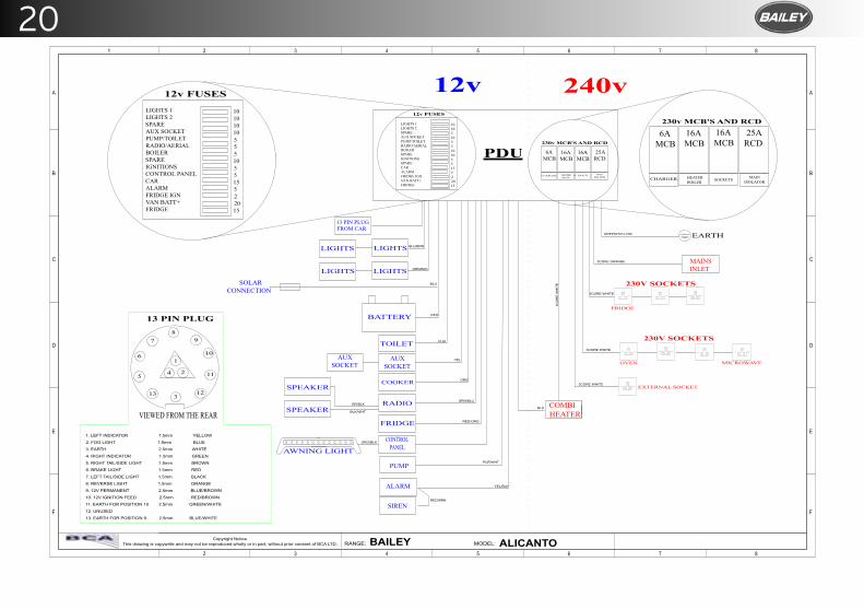
19
Copyright NoticeThis drawing is copywrite and may not be reproduced,wholly or in part, without prior consent of BCA LTD. RANGE: MODEL:
E
D
C
B
F
A
E
D
C
B
F
A
8765432
87654321
BAILEY ALICANTO
LIGHTS 1LIGHTS 2SPAREAUX SOCKETPUMP/TOILETRADIO/AERIALBOILERSPAREIGNITIONSSPARECARALARMFRIDGE IGNVAN BATT+FRIDGE
10105105510105515522015
EARTH
13 PIN PLUGFROM CAR
BATTERY
AUXSOCKET
TOILET
LIGHTS
MAINSINLET
12v 240v
PDU
8
1
4 2
312
11
10
97
6
5
13
VIEWED FROM THE REAR
13 PIN PLUG
12v FUSES
230V SOCKETS
FRIDGE
COMBIHEATER
25ARCD
SOCKETS MAINISOLATOR
230v MCB'S AND RCD
16AMCB
16AMCB
HEATERBOILER
6AMCB
CHARGER
230v MCB'S AND RCD
230V SOCKETS
6AMCB
16AMCB
16AMCB
25ARCD
CHARGER HEATERBOILER SOCKETS MAIN
ISOLATOR
LIGHTS
LIGHTSLIGHTS
SOLARCONNECTION
AUXSOCKET
COOKER
RADIO
SPEAKER
SPEAKER
FRIDGE
CONTROLPANEL PUMP
AWNING LIGHT
1. LEFT INDICATOR 1.5mm YELLOW
2. FOG LIGHT 1.5mm BLUE
3. EARTH 2.5mm WHITE
4. RIGHT INDICATOR 1.5mm GREEN
5. RIGHT TAIL/SIDE LIGHT 1.5mm BROWN
6. BRAKE LIGHT 1.5mm RED
7. LEFT TAIL/SIDE LIGHT 1.5mm BLACK
8. REVERSE LIGHT 1.5mm ORANGE
9. 12V PERMANENT 2.5mm BLUE/BROWN
10. 12V IGNITION FEED 2.5mm RED/BROWN
11. EARTH FOR POSITION 10 2.5mm GREEN/WHITE
12. UNUSED
13. EARTH FOR POSITION 9 2.5mm BLUE/WHITE
ALARM
SIREN
12v FUSES
LIGHTS 1LIGHTS 2SPAREAUX SOCKETPUMP/TOILETRADIO/AERIALBOILERSPAREIGNITIONSCONTROL PANELCARALARMFRIDGE IGNVAN BATT+FRIDGE
10101010555105515522015
OVEN MICROWAVE
EXTERNAL SOCKET
BLU/BRN
GRN/BLK
BLU
RED
PUR
YEL
ORG
GRN/BLUGR/BLK
BLK/WHT
RED/ORG
ORG/BLK
PUR/WHT
YEL/BLK
RED/BRN
BLU
3CO
RE
WH
ITE
3CORE WHITE
3CORE ORANGE
GREEN/YELLOW
3CORE WHITE
3CORE WHITE
20

31T
HE
SE
RV
ICE
MA
NU
AL
If the caravan is sold before the end of the original warranty the remaining period can be transferred to the new owner using the warranty transfer form. There is a fee charged for this service of £35 including VAT.Please send a copy of the Service Handbook, Proof of the purchase date along with this sheet and a copy of the service sheets from this service guide along with a cheque for £35 to Bailey of Bristol, South Liberty Lane, Bristol, BS3 2SS. Please make your cheque payable to “Bailey Caravans Ltd”. We are unable to accept any other form of payment.In order for the warranty to remain valid the caravan must have been serviced annually by an authorised Bailey Service Centre prior to the transfer of ownership. Failure to do so will invalidate any further warranty cover.Failure to request this transfer within 3 months of acquisition by the new owner will invalidate the remaining warranty.
Terms and Conditions apply.
MODEL
VIN NUMBER
PURCHASE DATE
PREVIOUS OWNER
NEW OWNER
NEW OWNER'S ADDRESS
NEW OWNER'S TELEPHONE NUMBER
NEW OWNER'S EMAIL ADDRESS
Signed: Date:
I have read and understood the terms and conditions of the warranty, including the servicing requirements, as applicable to this vehicle.
19
20

30
TH
E S
ER
VIC
E M
AN
UA
L
PAGE LEFT BLANK INTENTIONALLY
18
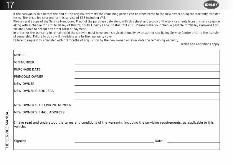
29T
HE
SE
RV
ICE
MA
NU
AL
If the caravan is sold before the end of the original warranty the remaining period can be transferred to the new owner using the warranty transfer form. There is a fee charged for this service of £35 including VAT.Please send a copy of the Service Handbook, Proof of the purchase date along with this sheet and a copy of the service sheets from this service guide along with a cheque for £35 to Bailey of Bristol, South Liberty Lane, Bristol, BS3 2SS. Please make your cheque payable to “Bailey Caravans Ltd”. We are unable to accept any other form of payment.In order for the warranty to remain valid the caravan must have been serviced annually by an authorised Bailey Service Centre prior to the transfer of ownership. Failure to do so will invalidate any further warranty cover.Failure to request this transfer within 3 months of acquisition by the new owner will invalidate the remaining warranty.
Terms and Conditions apply.
MODEL
VIN NUMBER
PURCHASE DATE
PREVIOUS OWNER
NEW OWNER
NEW OWNER'S ADDRESS
NEW OWNER'S TELEPHONE NUMBER
NEW OWNER'S EMAIL ADDRESS
Signed: Date:
I have read and understood the terms and conditions of the warranty, including the servicing requirements, as applicable to this vehicle.
17
18
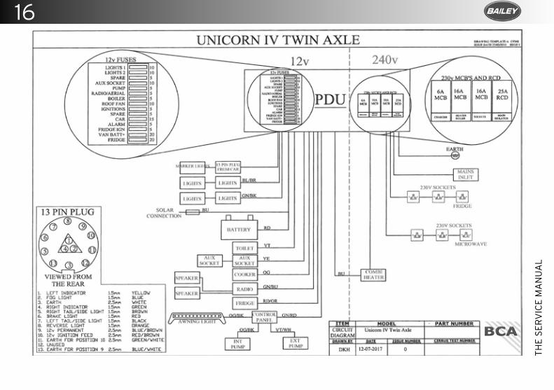
16
TH
E S
ER
VIC
E M
AN
UA
L
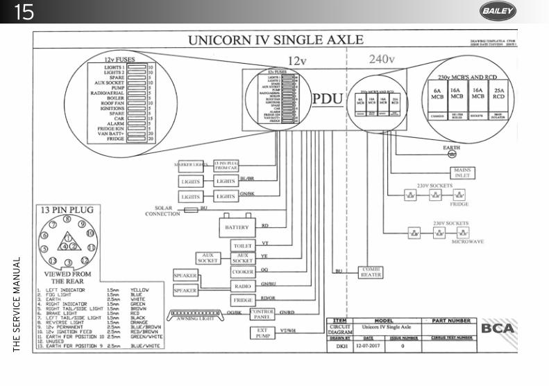
15T
HE
SE
RV
ICE
MA
NU
AL
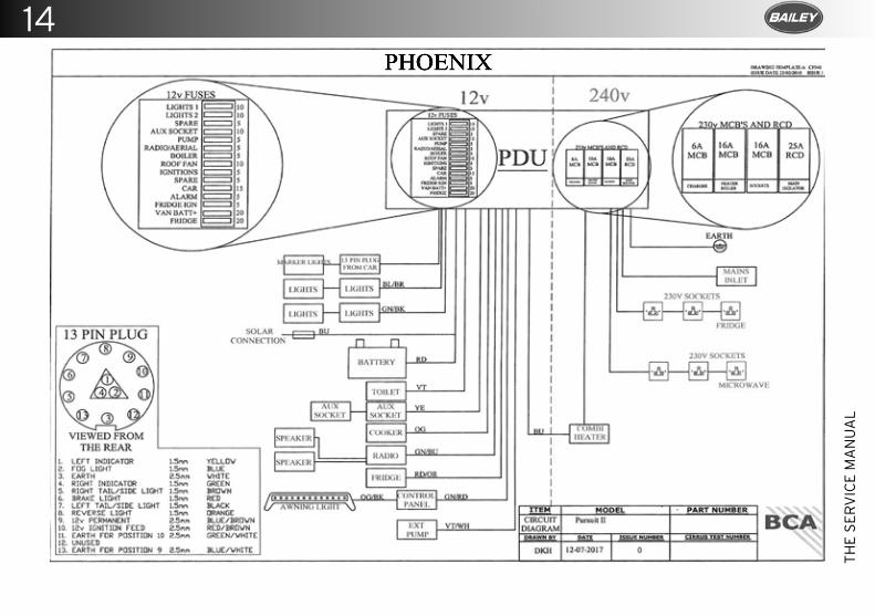
14
TH
E S
ER
VIC
E M
AN
UA
L
PHOENIX
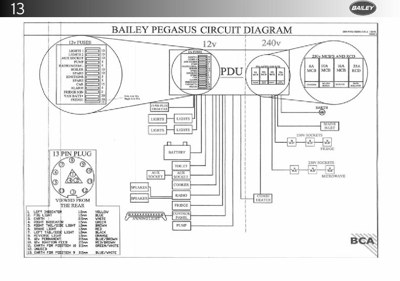
13T
HE
SE
RV
ICE
MA
NU
AL
15TH
E SE
RV
ICE
MA
NU
AL
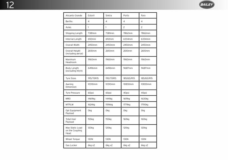
12
TH
E S
ER
VIC
E M
AN
UA
L
PAGE LEFT BLANK INTENTIONALLY
1
2021
Sea
son
Am
endm
ent
Alicanto Grande Estoril Sintra Porto Faro
Berths 4 4 4 4
Axles 1 1 2 2
Shipping Length 7381mm 7381mm 7862mm 7862mm
Internal Length 6112mm 6112mm 6334mm 6334mm
Overall Width 2450mm 2450mm 2450mm 2450mm
Overall Height (including aerial)
2610mm 2610mm 2610mm 2610mm
Maximum Headroom
1960mm 1960mm 1960mm 1960mm
Body Length (excluding hitch)
6496mm 6496mm 9687mm 9687mm
Tyre Sizes 195/70R15 195/70R15 185/65/R15 185/65/R15
Awning Dimension
10310mm 10310mm 10830mm 10830mm
Tyre Pressure 60psi 60psi 40psi 40psi
MRO 1469kg 1441kg 1619kg 1630kg
MTPLM 1624kg 1596kg 1779kg 1790kg
Opt Equipment Payload
0kg 0kg 0kg 0kg
Total User Payload
155kg 155kg 160kg 160kg
Max Static Load on the Coupling Head
120kg 120kg 120kg 120kg
Wheel Torque 130N 130N 130N 130N
Gas Locker 6kg x2 6kg x2 6kg x2 6kg x2
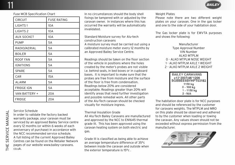
11T
HE
SE
RV
ICE
MA
NU
AL
Fuse MCB Specification Chart
CIRCUIT FUSE RATING
LIGHTS 1 10A
LIGHTS 2 10A
AUX SOCKET 10A
PUMP 5A
RADIO/AERIAL 5A
BOILER 5A
ROOF FAN 5A
IGNITIONS 5A
SPARE 5A
CAR 15A
ALARM 5A
FRIDGE IGN 5A
VAN BATTERY + 20A
FRIDGE 20A
Service ScheduleIn order to validate the factory backed warranty package, your caravan must be serviced by an approved Bailey Service centre every 12 months (or within 6 weeks of each anniversary of purchase) in accordance with the NCC recommended service schedule.A full listing of the current Approved Bailey Centres can be found on the Retailer Network pages of our website www.bailey-caravans.co.uk.
In no circumstances should the body shell fixings be tampered with or adjusted by the caravan owner. In instances where this has occurred the warranty will be automatically invalidated.
Standard Moisture survey for Alu-tech construction caravansA moisture survey must be carried out using a calibrated moisture meter every 12 months by an Approved Bailey Service Centre.
Readings should be taken on the floor section of the vehicle in positions where the holes created by the meter’s probes are not visible i.e. behind seals, in bed boxes or in cupboard bases. It is important to make sure that the probes are free from moisture and the surface of the floor is free from condensation.Readings below 20% are considered acceptable. Readings greater than 20% will identify areas that need further investigation and possible remedial work. All other parts of the Alu-Tech caravan should be checked visually for moisture ingress.
Thermal Insulation GradeAll Alu-Tech Bailey Caravans are manufactured and approved by the NCC to EN1645 thermal grade III. This has been approved using the caravan heating system on both electric and gas.
Grade III is classified as being able to achieve an average temperature difference of 35°c between inside the caravan and outside when the exterior temperature is 15°c .
Weight PlatesPlease note there are two different weight plates on your caravan. One in the gas locker and one to the side of your habitation door.
The Gas locker plate is for EWVTA purposes and shows the following:
Manufacturer Type Approval Number
VIN NumberALKO MTPLM
0 - ALKO MTPLM NOSE WEIGHT1 - ALKO MTPLM AXLE 1 WEIGHT2 - ALKO MTPLM AXLE 2 WEIGHT
The habitation door plate is for NCC purposes and should be referenced by the customer for caravans weights. The MTPLM and MRO on this plate should be observed and adhered to by the customer when loading or towing the caravan. Any values shown should not be exceeded without express permission from the manufacturer.
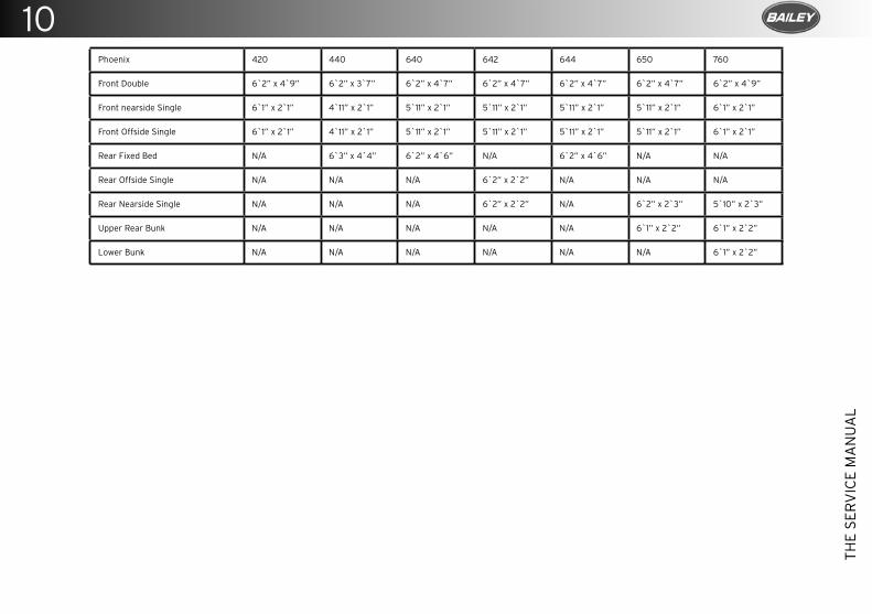
10
TH
E S
ER
VIC
E M
AN
UA
L
Phoenix 420 440 640 642 644 650 760
Front Double 6`2” x 4`9” 6`2” x 3`7” 6`2” x 4`7” 6`2” x 4`7” 6`2” x 4`7” 6`2” x 4`7” 6`2” x 4`9”
Front nearside Single 6`1” x 2`1” 4`11” x 2`1” 5`11” x 2`1” 5`11” x 2`1” 5`11” x 2`1” 5`11” x 2`1” 6`1” x 2`1”
Front Offside Single 6`1” x 2`1” 4`11” x 2`1” 5`11” x 2`1” 5`11” x 2`1” 5`11” x 2`1” 5`11” x 2`1” 6`1” x 2`1”
Rear Fixed Bed N/A 6`3” x 4`4” 6`2” x 4`6” N/A 6`2” x 4`6” N/A N/A
Rear Offside Single N/A N/A N/A 6`2” x 2`2” N/A N/A N/A
Rear Nearside Single N/A N/A N/A 6`2” x 2`2” N/A 6`2” x 2`3” 5`10” x 2`3”
Upper Rear Bunk N/A N/A N/A N/A N/A 6`1” x 2`2” 6`1” x 2`2”
Lower Bunk N/A N/A N/A N/A N/A N/A 6`1” x 2`2”
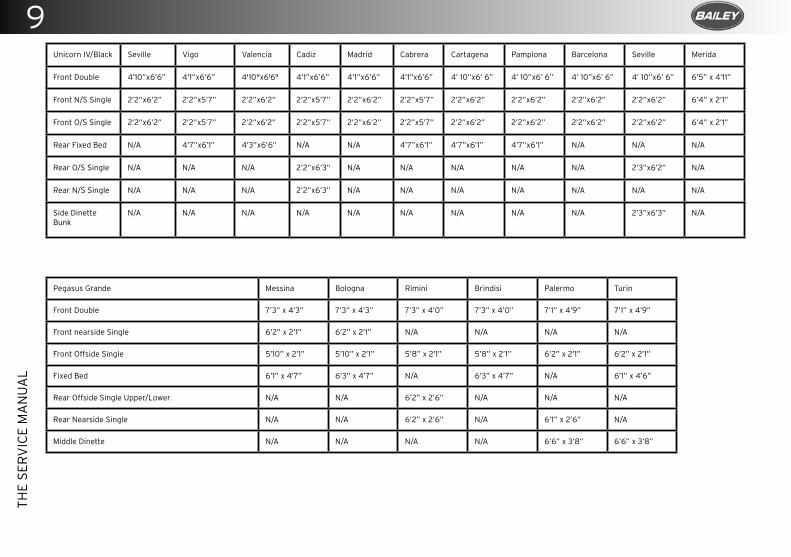
9T
HE
SE
RV
ICE
MA
NU
AL
Unicorn IV/Black Seville Vigo Valencia Cadiz Madrid Cabrera Cartagena Pamplona Barcelona Seville Merida
Front Double 4’10”x6’6” 4’1”x6’6” 4'10"x6'6" 4’1”x6’6” 4’1”x6’6” 4’1”x6’6” 4’ 10”x6’ 6” 4’ 10”x6’ 6” 4’ 10”x6’ 6” 4’ 10”x6’ 6” 6’5” x 4’11”
Front N/S Single 2’2”x6’2” 2’2”x5’7” 2’2”x6’2” 2’2”x5’7” 2’2”x6’2” 2’2”x5’7” 2’2”x6’2” 2’2”x6’2” 2’2”x6’2” 2’2”x6’2” 6’4” x 2’1”
Front O/S Single 2’2”x6’2” 2’2”x5’7” 2’2”x6’2” 2’2”x5’7” 2’2”x6’2” 2’2”x5’7” 2’2”x6’2” 2’2”x6’2” 2’2”x6’2” 2’2”x6’2” 6’4” x 2’1”
Rear Fixed Bed N/A 4’7”x6’1” 4’3”x6’6” N/A N/A 4’7”x6’1” 4’7”x6’1” 4’7”x6’1” N/A N/A N/A
Rear O/S Single N/A N/A N/A 2’2”x6’3” N/A N/A N/A N/A N/A 2’3”x6’2” N/A
Rear N/S Single N/A N/A N/A 2’2”x6’3” N/A N/A N/A N/A N/A N/A N/A
Side Dinette Bunk
N/A N/A N/A N/A N/A N/A N/A N/A N/A 2’3”x6’3” N/A
Pegasus Grande Messina Bologna Rimini Brindisi Palermo Turin
Front Double 7’3” x 4’3” 7’3” x 4’3” 7’3” x 4’0” 7’3” x 4’0” 7’1” x 4’9” 7’1” x 4’9”
Front nearside Single 6’2” x 2’1” 6’2” x 2’1” N/A N/A N/A N/A
Front Offside Single 5’10” x 2’1” 5’10” x 2’1” 5’8” x 2’1” 5’8” x 2’1” 6’2” x 2’1” 6’2” x 2’1”
Fixed Bed 6’1” x 4’7” 6’3” x 4’7” N/A 6’3” x 4’7” N/A 6’1” x 4’6”
Rear Offside Single Upper/Lower N/A N/A 6’2” x 2’6” N/A N/A N/A
Rear Nearside Single N/A N/A 6’2” x 2’6” N/A 6’1” x 2’6” N/A
Middle Dinette N/A N/A N/A N/A 6’6” x 3’8” 6’6” x 3’8”
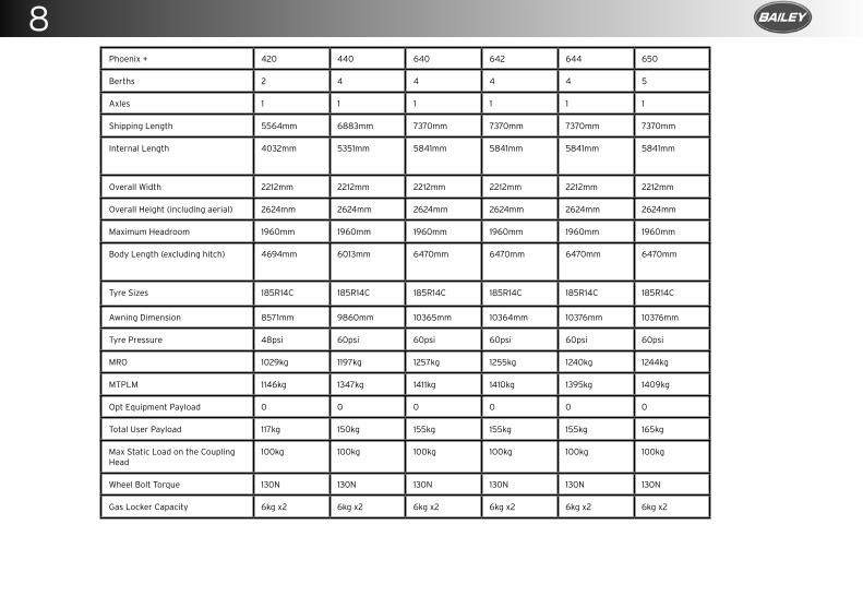
8
TH
E S
ER
VIC
E M
AN
UA
L
Phoenix 420 440 640 642 644 650 760
Berths 2 4 4 4 4 5 6
Axles 1 1 1 1 1 1 2
Shipping Length 5564mm 6883mm 7370mm 7370mm 7370mm 7370mm 7864mm
Internal Length 4032mm 5351mm 5841mm 5841mm 5841mm 5841mm 6334mm
Overall Width 2212mm 2212mm 2212mm 2212mm 2212mm 2212mm 2212mm
Overall Height (including aerial) 2624mm 2624mm 2624mm 2624mm 2624mm 2624mm 2624mm
Maximum Headroom 1960mm 1960mm 1960mm 1960mm 1960mm 1960mm 1960mm
Body Length (excluding hitch) 4694mm 6013mm 6470mm 6470mm 6470mm 6470mm 6993mm
Tyre Sizes 185R14C 185R14C 185R14C 185R14C 185R14C 185R14C 185/65R14
Awning Dimension 8571mm 9860mm 10365mm 10364mm 10376mm 10376mm 10799mm
Tyre Pressure 48psi 60psi 60psi 60psi 60psi 60psi 35psi
MRO 1022kg 1166kg 1227kg 1227kg 1219kg 1223kg 1420kg
MTPLM 1139kg 1316kg 1382kg 1382kg 1374kg 1388kg 1600kg
Opt Equipment Payload 0 0 0 0 0 0 0
Total User Payload 117kg 150kg 155kg 155kg 155kg 165kg 180kg
Max Static Load on the Coupling Head
100kg 100kg 100kg 100kg 100kg 100kg 100kg
Wheel Bolt Torque 130N 130N 130N 130N 130N 130N 130N
Gas Locker Capacity 6kg x2 6kg x2 6kg x2 6kg x2 6kg x2 6kg x2 6kg x2
3
2021
Sea
son
Am
endm
ent
Phoenix + 420 440 640 642 644 650
Berths 2 4 4 4 4 5
Axles 1 1 1 1 1 1
Shipping Length 5564mm 6883mm 7370mm 7370mm 7370mm 7370mm
Internal Length 4032mm 5351mm 5841mm 5841mm 5841mm 5841mm
Overall Width 2212mm 2212mm 2212mm 2212mm 2212mm 2212mm
Overall Height (including aerial) 2624mm 2624mm 2624mm 2624mm 2624mm 2624mm
Maximum Headroom 1960mm 1960mm 1960mm 1960mm 1960mm 1960mm
Body Length (excluding hitch) 4694mm 6013mm 6470mm 6470mm 6470mm 6470mm
Tyre Sizes 185R14C 185R14C 185R14C 185R14C 185R14C 185R14C
Awning Dimension 8571mm 9860mm 10365mm 10364mm 10376mm 10376mm
Tyre Pressure 48psi 60psi 60psi 60psi 60psi 60psi
MRO 1029kg 1197kg 1257kg 1255kg 1240kg 1244kg
MTPLM 1146kg 1347kg 1411kg 1410kg 1395kg 1409kg
Opt Equipment Payload 0 0 0 0 0 0
Total User Payload 117kg 150kg 155kg 155kg 155kg 165kg
Max Static Load on the Coupling Head
100kg 100kg 100kg 100kg 100kg 100kg
Wheel Bolt Torque 130N 130N 130N 130N 130N 130N
Gas Locker Capacity 6kg x2 6kg x2 6kg x2 6kg x2 6kg x2 6kg x2
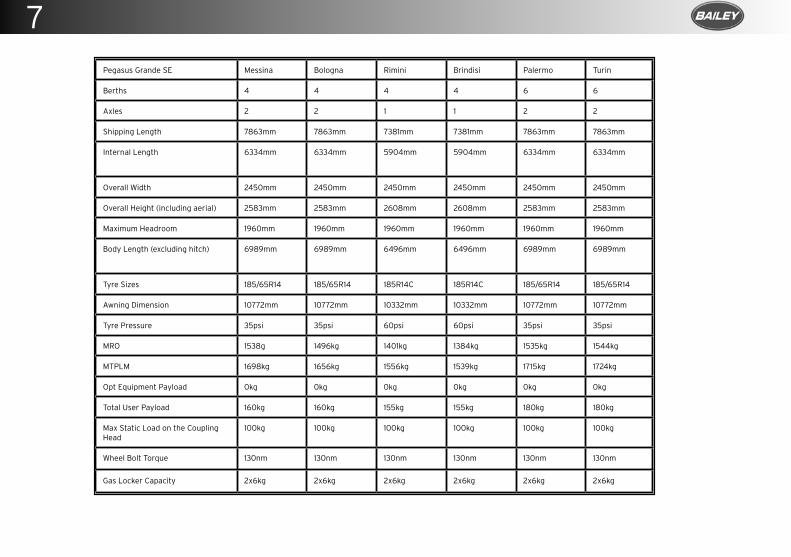
7T
HE
SE
RV
ICE
MA
NU
AL
Pegasus Grande Messina Bologna Rimini Brindisi Palermo Turin
Berths 4 4 4 4 6 6
Axles 2 2 1 1 2 2
Shipping Length 7863mm 7863mm 7381mm 7381mm 7863mm 7863mm
Internal Length 6334mm 6334mm 5904mm 5904mm 6334mm 6334mm
Overall Width 2450mm 2450mm 2450mm 2450mm 2450mm 2450mm
Overall Height (including aerial) 2583mm 2583mm 2608mm 2608mm 2583mm 2583mm
Maximum Headroom 1960mm 1960mm 1960mm 1960mm 1960mm 1960mm
Body Length (excluding hitch) 6989mm 6989mm 6496mm 6496mm 6989mm 6989mm
Tyre Sizes 185/65R14 185/65R14 185R14C 185R14C 185/65R14 185/65R14
Awning Dimension 10772mm 10772mm 10332mm 10332mm 10772mm 10772mm
Tyre Pressure 35psi 35psi 60psi 60psi 35psi 35psi
MRO 1510kg 1481kg 1345kg 1335kg 1513kg 1507kg
MTPLM 1669kg 1640kg 1500kg 1490kg 1692kg 1686kg
Opt Equipment Payload 0kg 0kg 0kg 0kg 0kg 0kg
Total User Payload 159kg 159kg 155kg 155kg 179kg 179kg
Max Static Load on the Coupling Head
100kg 100kg 100kg 100kg 100kg 100kg
Wheel Bolt Torque 130nm 130nm 130nm 130nm 130nm 130nm
Gas Locker Capacity 2x6kg 2x6kg 2x6kg 2x6kg 2x6kg 2x6kg
2Pegasus Grande SE Messina Bologna Rimini Brindisi Palermo Turin
Berths 4 4 4 4 6 6
Axles 2 2 1 1 2 2
Shipping Length 7863mm 7863mm 7381mm 7381mm 7863mm 7863mm
Internal Length 6334mm 6334mm 5904mm 5904mm 6334mm 6334mm
Overall Width 2450mm 2450mm 2450mm 2450mm 2450mm 2450mm
Overall Height (including aerial) 2583mm 2583mm 2608mm 2608mm 2583mm 2583mm
Maximum Headroom 1960mm 1960mm 1960mm 1960mm 1960mm 1960mm
Body Length (excluding hitch) 6989mm 6989mm 6496mm 6496mm 6989mm 6989mm
Tyre Sizes 185/65R14 185/65R14 185R14C 185R14C 185/65R14 185/65R14
Awning Dimension 10772mm 10772mm 10332mm 10332mm 10772mm 10772mm
Tyre Pressure 35psi 35psi 60psi 60psi 35psi 35psi
MRO 1538g 1496kg 1401kg 1384kg 1535kg 1544kg
MTPLM 1698kg 1656kg 1556kg 1539kg 1715kg 1724kg
Opt Equipment Payload 0kg 0kg 0kg 0kg 0kg 0kg
Total User Payload 160kg 160kg 155kg 155kg 180kg 180kg
Max Static Load on the Coupling Head
100kg 100kg 100kg 100kg 100kg 100kg
Wheel Bolt Torque 130nm 130nm 130nm 130nm 130nm 130nm
Gas Locker Capacity 2x6kg 2x6kg 2x6kg 2x6kg 2x6kg 2x6kg
2021
Sea
son
Am
endm
ent
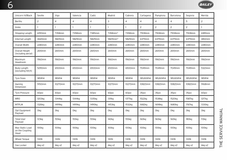
6
TH
E S
ER
VIC
E M
AN
UA
L
Unicorn IV/Black Seville Vigo Valencia Cadiz Madrid Cabrera Cartagena Pamplona Barcelona Segovia Merida
Berths 2 4 4 4 3 4 4 4 4 5 2
Axles 1 1 1 1 1 1 2 2 2 2 1
Shipping Length 6190mm 7358mm 7358mm 7385mm 7358mm* 7358mm 7908mm 7908mm 7908mm 7908mm 6189mm
Internal Length 4665mm 5829mm 5829mm 5829mm 5829mm* 5829mm 6379mm 6379mm 6379mm 6379mm 4812mm
Overall Width 2280mm 2280mm 2280mm 2280mm 2280mm 2280mm 2280mm 2280mm 2280mm 2280mm 2280mm
Overall Height (including aerial)
2610mm 2610mm 2610mm 2610mm 2610mm 2610mm 2610mm 2610mm 2610mm 2610mm 2610mm
Maximum Headroom
1960mm 1960mm 1960mm 1960mm 1960mm 1960mm 1960mm 1960mm 1960mm 1960mm 1960mm
Body Length (excluding hitch)
5290mm 6500mm 6500mm 6500mm 6500mm 6500mm 7049mm 7049mm 7049mm 7049mm 5323mm
Tyre Sizes 185R14 185R14 185R14 185R14 185R14 185R14 185/65R14 185/65R14 185/65R14 185/65R14 185R14
Awning Dimension
9150mm 10270mm 10270mm 10270mm 10270mm 10270mm 10820mm 10820mm 10820mm 10820mm 9168mm
Tyre Pressure 60psi 60psi 60psi 60psi 60psi 60psi 35psi 35psi 35psi 35psi 60psi
MRO 1203kg 1344kg 1344kg 1335kg 1311kg 1377kg 1522kg 1538kg 1520kg 1587kg 1217kg
MTPLM 1326kg 1499kg 1499kg 1490kg 1453kg 1532kg 1682kg 1698kg 1680kg 1767kg 1330kg
Opt Equipment Payload
0kg 0kg 0kg 0kg 0kg 0kg 0kg 0kg 0kg 0kg 0kg
Total User Payload
123kg 155kg 155kg 155kg 142kg 155kg 160kg 160kg 160kg 180kg 113kg
Max Static Load on the Coupling Head
100kg 100kg 100kg 100kg 100kg 100kg 100kg 100kg 100kg 100kg 100kg
Wheel Torque 130N 130N 130N 130N 130N 130N 130N 130N 130N 130N 130N
Gas Locker 6kg x2 6kg x2 6kg x2 6kg x2 6kg x2 6kg x2 6kg x2 6kg x2 6kg x2 6kg x2 6kg x2
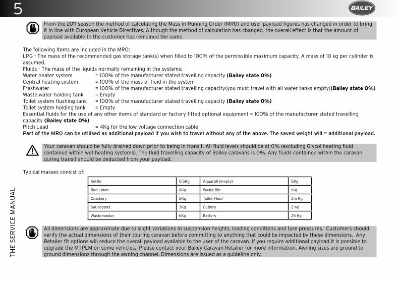
5T
HE
SE
RV
ICE
MA
NU
AL
From the 2011 season the method of calculating the Mass in Running Order (MRO) and user payload figures has changed in order to bring it in line with European Vehicle Directives. Although the method of calculation has changed, the overall effect is that the amount of payload available to the customer has remained the same.
The following Items are included in the MRO:LPG - The mass of the recommended gas storage tank(s) when filled to 100% of the permissible maximum capacity. A mass of 10 kg per cylinder is assumed.Fluids - The mass of the liquids normally remaining in the systems:Water heater system = 100% of the manufacturer stated travelling capacity (Bailey state 0%)Central heating system = 100% of the mass of fluid in the system Freshwater = 100% of the manufacturer stated travelling capacity(you must travel with all water tanks empty)(Bailey state 0%)Waste water holding tank = EmptyToilet system flushing tank = 100% of the manufacturer stated travelling capacity (Bailey state 0%)Toilet system holding tank = EmptyEssential fluids for the use of any other items of standard or factory fitted optional equipment = 100% of the manufacturer stated travelling capacity (Bailey state 0%)Pitch Lead = 4Kg for the low voltage connection cablePart of the MRO can be utilised as additional payload if you wish to travel without any of the above. The saved weight will = additional payload.
Your caravan should be fully drained down prior to being in transit. All fluid levels should be at 0% (excluding Glycol heating fluid contained within wet heating systems). The fluid travelling capacity of Bailey caravans is 0%. Any fluids contained within the caravan during transit should be deducted from your payload.
Typical masses consist of:
Kettle 0.5Kg Aquaroll (empty) 5Kg
Bed Linen 6Kg Waste Bin 1Kg
Crockery 5Kg Toilet Fluid 2.5 Kg
Saucepans 3Kg Cutlery 2 Kg
Wastemaster 6Kg Battery 25 Kg
All dimensions are approximate due to slight variations in suspension heights, loading conditions and tyre pressures. Customers should verify the actual dimensions of their touring caravan before committing to anything that could be impacted by these dimensions. Any Retailer fit options will reduce the overall payload available to the user of the caravan. If you require additional payload it is possible to upgrade the MTPLM on some vehicles. Please contact your Bailey Caravan Retailer for more information. Awning sizes are ground to ground dimensions through the awning channel. Dimensions are issued as a guideline only.
4
TH
E S
ER
VIC
E M
AN
UA
L
11th Year Service
12th Year Service
13th Year Service
14th Year Service
15th Year Service
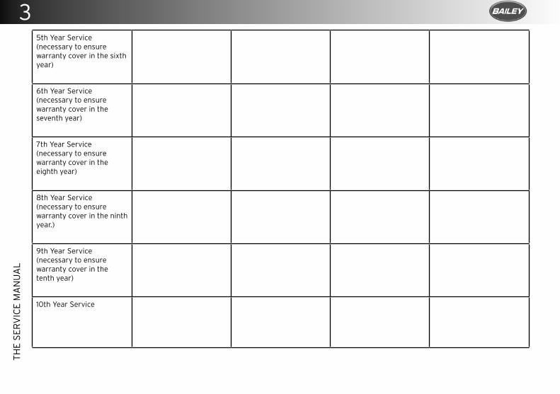
3T
HE
SE
RV
ICE
MA
NU
AL
5th Year Service (necessary to ensure warranty cover in the sixth year)
6th Year Service (necessary to ensure warranty cover in the seventh year)
7th Year Service (necessary to ensure warranty cover in the eighth year)
8th Year Service (necessary to ensure warranty cover in the ninth year.)
9th Year Service (necessary to ensure warranty cover in the tenth year)
10th Year Service
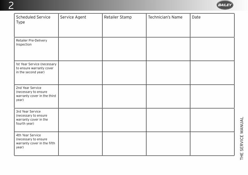
2
TH
E S
ER
VIC
E M
AN
UA
L
Scheduled Service Type
Service Agent Retailer Stamp Technician’s Name Date
Retailer Pre-Delivery Inspection
1st Year Service (necessary to ensure warranty cover in the second year)
2nd Year Service (necessary to ensure warranty cover in the third year)
3rd Year Service (necessary to ensure warranty cover in the fourth year)
4th Year Service (necessary to ensure warranty cover in the fifth year)

1T
HE
SE
RV
ICE
MA
NU
AL
©COPYRIGHT 2020 BAILEY OF BRISTOL LIMITED

Nearly 50 years ago, Bailey Owners Club was built on a foundation of friendship, fun and freedom. The Club is run by and for members and is dedicated to the hobby of rallying with
Bailey caravans and motorhomes. Rallies are held across the UK, with a diverse range of activities suitable for all ages.
Biennially Bailey open the factory exclusively for Bailey Owners Club members.
The Club fundraises for a range of charities throughout the year.
It couldn’t be easier to join - simply go to www.baileyownersclub.org for details on how to become a member.
More than
up to it Go anywhere, do everything
We love using our caravans and motorhomes as much as you do.
In recent years we have gone on a number of our own adventures across the world, journeying as far afield as Finland, Turkey and even Australia!
We’d really like to hear about where you go and what you do on your travels with your new Bailey, so why not share your stories with us on our social media pages?
Join our community:
www.baileyofbristol.co.uk
Caravan Owners Manual October 2020