Embed Size (px)
Citation preview

OAIGNEPCaratteristiche tecniche / Technical chara
020 - 025 - 032 - 040 - 050 -
Pressioni / Pressures
Filetiature / ThreadsMaschi gas conico IS07Male threads taper in conformity with ISOFemmine gas cilindrica IS0228Female threads in conformity with ISO 228
4
cteristics
Materiali e componenti / Component part and materials1 Dado in Ottone Nichelato
2 Guarnizione in NBR
3 Pinza D'aggraffaggio in INOX AISI 304
4 Guarnizione 0-RING in NBR
5 Anello di Sicurezza in Tecnopolimero
6 Corpo in Ottone Nichelato
7 Tubo in alluminio estruso verniciato calibratoColore Blu (RAL 5010) - Colore Grigio (RAL 7035).
Pressione minima / Minimum pressure -0.99 bar ( (2099 Mpa)Pressione massima / Maximum pressure 16 bar (1.6 Mpa)
Fluidi compatibili / Compatible flukis il
Aria compressa / Compressed air.Vuoto / VacuumGas inerti (AZOTO, ARGON) / Inert Gas (AZOTO, ARGON)
1 Nut made in Nickel-Plated Brass
2 Seal made in NBR
3 Clamping Washer made in Inox AISI 304
4 0-RING Seals made in NBR
5 Safety Ring made in Technopolymeric
6 Body made in Nickel-Plated Brass
7 Extruded Alluminium tube calibrated and powder coal-edBlue Color (RAL 5010) - Gray Color (RAL 7035).
Temperature / TemperaturesTemperatura minima / Minimum temperature -20°CTemperatura massima / Maximum temperature +80°C
Tenuta al fuoco / Fire resistanceII sistema non alimenta e non propaga ii fuocoThe system does not stroke or propagate any fires
Caratteristiche tecniche dei tubiTechnical characteristics to the tubesAlluminio estrusoExtruded Aluminium
Designazioni UNI EN 573-3Designations UNI EN 573-3
Trattamento superficialeSurface treatment
Peso specificoSpecif ic weight
Coefficiente di dilatazioneExpansion coeffic ie n t
0.024 mm/(m °C)
PUSH-IN
UNI 9006/1 Al Mg 0.5 Si 0.4 Fe 0.2
EN AW 6060 16
Verniciatura elettrostaticaElectrostahc painting2.70 Kg/dm3
Aignep si riserva ii diritho di variare modelli e ingombri senza preavviso. AGGIORNAMENTO: 07 MARZO 2012Aignep reserves the right to vary models and dimensions without notice. UPDATED MARCH 07, 2012
OAIGNEP01 10
Pressioni / Pressures,
Materiali e componenti / Component par t and ma=11 Dado in alluminio trattato superficialmente
2 Guarnizione 0-RING in NBR
3 Corpo in alluminio trattato superficialmente
4 Anello di sicurezza in Tecnopolimero
5 Pinza d'aggraffaggio in INOX AISI 301
6 Anello guida-tubo in Tecnopolimero
7 Dado autobloccante in acciaio zincato
8 Vite TCEI in acciaio zincato
9 Tubo in alluminio estruso verniciato calibratoColore Blu (RAL 5010) - Colore Grigio (RAL 7035).
Pressione minima / Minimum pressure -0.99 bar (0.099 Mpa)Pressione massima / Maximum pressure 16 bar (1.6 Mpa)
Fluidi compatibili / Compatible fluiC1711.
Aria compressa / Compressed air.Vuoto / VacuumGas inerti (AZOTO, ARGON) / Inert Gas (AZOTO, ARGON)
Filettature / ThreadsRaccordo flangiato UNI EN 1092 - 4 PN 16
Raccordo flangiato DIN UNI EN 1092 - 4 PN 16Femmine gas cilindrica 130228Female threads in conformity with ISO 228
4
Aignep si riserva ii diritho di variare rnodelli e ingornbri senza preavviso. AGGIORNAMENTO: 07 MARZO 2012Aignep reserves the right to vary models a nd dimensions without notice. UPDATED MARCH 07, 2012
9
Temperature / Temperatures
Tenuta al fuoco / Fire resistanceII sistema non alimenta e non propaga ii fuocoThe system does not stroke or propagate any fires
PUSH-IN
1 Nut made in aluminium with finished surface treatment
2 0-RING Seal made in NBR
3 Body made in aluminium with finished surface treatment
4 Safety Ring made in Technopolymeric
5 Clamping Washer made in AISI 301
6 Tube-guide Ring made in technopolymeric
7 Selflocking Nut in Zinc-Plated Steel
8 TCEI Screw in Zinc-Plated Steel
9 Extruded Alluminium tube calibrated and powder c o d e dBlue Color (RAL 5010) - Grey Color (RAL 7035).
Temperatura minima / Minimum temperature -20°CT emper a tu ra m ass im a / Maximum temperature +80°C
Caratleristiche tecniche dei tualmIrTechnical characteristics to the tubesAlluminio estruso UN19006/1 Al Mg 0.5 Si 0.4 Fe 0.2Extruded Aluminium
Designazioni UNI EN 573-3 EN AW 6060 T6Designations UNI EN 573-3
Traffamento superficiale Verniciatura elettrostaticaSurface treatment Electrostatic paintingPeso specifico 2.70 Kg/dm3Specific weight
Coefficiente di dilatazione 0.024 mm/(m °C)Expansion coeff ic ient
5
OAIGNEPMontaggio Impianto - Installation 020 - 025 - 032 --WO
L:::1
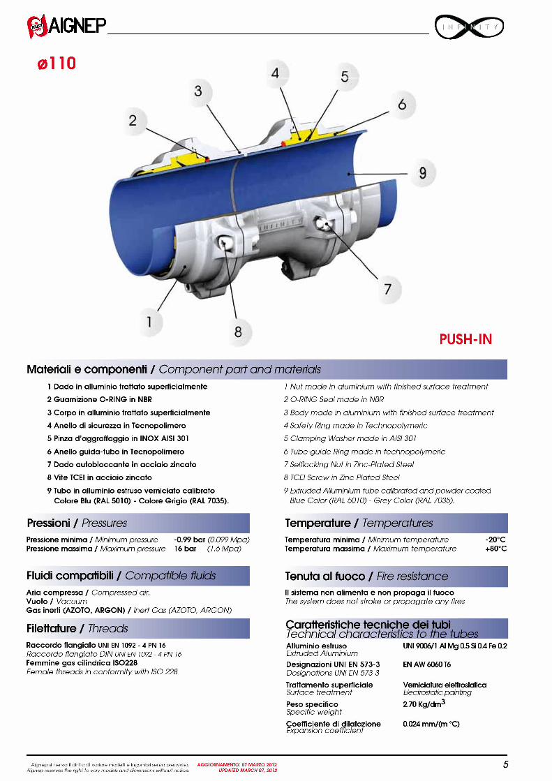
2 Inserire ii tubo nel raccordo sino in battuta per la connessioneautomatica.Push tube into the fitting for automatic connection.
Nel caso si dovesse smontare un raccordo, utilizzare le coppiedi serraggio riportate in tabella per il successivo montaggio.In case of fitting disassembling, use the torques as in the chart tore-assemble the fitting.
Montaggio Impianto - Installation 050 - 06
r --71
6
z2 Inserire il tubo nel raccordo sino in
battuta per la connessione e serrareil dado util izzando la coppia diserraggio riportata in tabella.Push tube into the Wing forconnection and tighten the nut us ingtorques as in the chart.
1
3
2
1 I raccordi 020 - 025 - 0 32 - as 40 sono premontati con dado giáserrato. I tubi di 4 e 6 mt sono giá verniciati, calibrati e sbavati.Fittings of 020 - 025 - o 32 - 0 40 are pre-assembled. Tubes of4 & 6 mt are pre-coated, calibrated and burred.
2
Diametro CoppiaDiameter Torque
20 300 cN.m
25 300 cN.m
32 400 cN.m
40 650 cN.m
3
I raccordi 050 - 063 sono premontati con dado allentato perfacilitare l'inserimento del tubo. I tubi di 4 e 6 mt sono giáverniciati,calibrati e sbavati.Fittings of 050 - 063 are pre-assembled with nut untwisted to helptube connection. Tubes of 4 & 6 mt are pre-coated, calibratedand burred.
Diametro CoppiaDiameter Torque
50 75 N.m
63 75 N.m
Aignep si riserva ii diritho di variare modelli e ingombri senza preavviso. AGGIORNAMENTO: 07 MARZO 2012Aignep reserves the right to vary models and dimensions without notice. UPDATED MARCH 07, 2012
OAIGNEPMontaggio Impianto - Installation 01
Inserimento
11-
-4 ‘
Aignep si riserva ii diritho di variare rnodelli e ingornbri senza preavviso. AGGIORNAMENTO: 07 MARZO 2012Aignep reserves the right to vary models a nd dimensions without notice. UPDATED MARCH 07, 2012
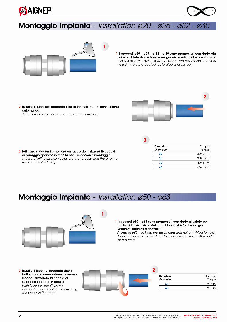
DiametroDiameter
20
25
32
40
50
63
110
10
1
1 I raccordi 0110 sono premontati con quattro viti allentate perfacilitare l'inserimento del tubo. I tubi di 4 e 6 mt sono giáverniciati,calibrati e sbavati.Fittings of 0110 are pre-assembled with four screws untwisted tohelp tube connection. Tubes o f 4 & 6 mt are pre-coated,calibrated and burred.
2 Inserire ii tubo nel raccordo sino in battuta per la connessione automatica e stringere le quattro viti nella sequenza suggerita.Coppia di serraggio 30Nm.Push tube into the fitting for automatic connection and screw up in the suggested sequence. Tightening torque 30Nm.
tubo - Tube Connection
La corretta connessione del tubo e confermata dalla posizio-ne della freccia pre marcata. In caso esistesse la necessitá ditagliare ii tubo, si consigia di segnare la lunghezza del tubo cheva inserita nel raccordo.
The correct connection of tube is confirmed by the position of thearrow pre-stamp. If you need to cut the tube, mark the dis tanceof tube to insert in the fitting.
mm
31.5 mm
38.5 mm
46 mm
52 mm
63.5 mm
75.5 mm
125.5 mm
7

PortataFlow Rate
NI/min Nm3/h cfm 25m82ft
Distanza fra compressoreDistance between compressor
50m 100m 150m 200m164ft 328ft 4929 656ft
ande utilizzo piú lontano
the most distant using point.
400m 500m 1000m 1500m1312ft 16409 3280ft 4921ft
2000m65629
300m984ft
230 14 8 20 20 20 20 20 20 20 20 20 25 25650 39 23 20 20 20 20 25 25 25 25 32 32 32900 54 32 20 20 20 25 25 25 32 32 32 40 401200 72 42 20 20 25 25 25 32 32 32 40 40 401750 1::::: .:2 20 25 25 32 32 32 32 40 40 50 502000 120 71 20 25 32 32 32 32 40 40 40 50 502500 150 88 25 25 32 32 32 40 40 40 50 50 503000 180 106 25 32 32 32 40 40 40 40 50 50 633500 210 124 25 32 32 40 40 40 40 50 50 63 634500 270 159 32 32 40 40 40 50 50 50 63 63 636000 360 212 32 40 40 40 50 50 50 63 63 63 63*7000 420 247 32 40 40 50 50 50 63 63 63 63* 1108500 510 300 40 40 50 50 50 63 63 63 63* 110 11012000 720 424 40 50 50 63 63 63 63 110 110 110 11015000 900 530 40 50 63 63 63 63 63* 110 110 110 11018000 1080 636 50 50 63 63 63 110 110 110 110 110 11021000 1260 742 50 63 63 63 63* 110 110 110 110 110 110*26000 1560 918 50 63 63 63* 110 110 110 110 110 110* 110*31000 1860 1095 63 63 63* 110 110 110 110 110 110 110* 110*33000 1980 1165 63 63 110 110 110 110 110 110 110* 110* 110*44000 2640 1554 63 63* 110 110 110 110 110 110 110* 110* 110*50000 3000 1766 63 110 110 110 110 110 110 110* 110* 110* 110*58000 3480 2048 63 110 110 110 110 110 110* 110* 110* 110* 110*67000 4020 2366 63* 110 110 110 110 110* 110* 110* 110* 110* 110*75000 4500 2648 110 110 110 110 110 110* 110* 110* 110* 110* 110*83000 4980 2931 110 110 110 110 110* 110* 110* 110* 110* 110* 110*92000 5520 3249 110 110 110 110* 110* 110* 110* 110* 110* 110* 110*100000 6000 3531 110 110 110 110* 110* 110* 110* 110* 110* 110* 110*
AIGNEP
Dimensionamento della rete / Chose the diameter four
La tabella sottostante permette di determinare ii diametro della linea principale.The Diagram below allows to determinate the diameter of the main line.
1 Trovare la portata del compressore nella colonna rossa.Choose the Flow rate of compressor in the Red column.
2 Trovare la distanza fra compressore e utilizzo piu' lontano nella riga blu.Choose the Distance between compressor and the most distant using point in the Blue column.
3 Trovare il diametro incrociando la riga della portata con la colonna della distanza.Cross the lines of Flow rate and blue column of Distance to choose the diameter.
Esempio / ExamplePortata: 1750 NL/min
Distanza fra compressore eutilizzo piú lontano: 300 m
Diametro tubo:
8
32
Pressione 7 bar - Perdita di carico totale 4% / Pressure 7 bar - Total pressure drop 4%* La perdita di carico e superiore al 4% / * Pressure drop is higher than 4%
Flow rate: 1750 NL/min
Distance between compressorand most distant using point: 300 m
Tube diameter: 32
'he installation
Aignep si riservo ii diritto di voriore modelli e ingombri senzo preovviso. AGGIORNAMENTO: 07 MARZO 2012Aignep reserves the fight to vary models and dimensions without notice. UPDATED MARCH 07, 2012
fjAIGNEP D C )
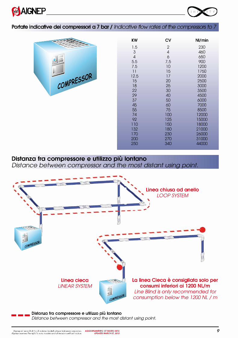
Portate indicative dei compressori a 7 bar / Indicative flow rates of the compressors to 7
Distanza fra compressore e utilizzo piú lontanoDistance between compressor and the most distant using po
a
N .4\
N X
r # M C ---_-.1 M . ` 9:797,1L
-• • • • —
comPRE5
1-■• •• • -
1, 0 0 0 H
l i a l _ i i i) 4 1
1
_ñn R
caw"c550
Linea ciecaLINEAR SYSTEM
. . ■ • •
-
RIM• . . • ■ •, M = 1 -
4* - i n i m ■ I = M 6
NNS
rE4111 1 1. 1111111111111tr - . .
.•■._ L
11...J ,soR,4coo—
Aignep si riserva ii diritto di variere rnodelli e ingornbri serve preevviso. AGGIORNAMENTO: 07 MARZO 2012Aignep reserves the right to vary models and dimensions without notice. UPDATED MARCH 07, 2012
1.5 2 2303 4 4604 6 650
5.5 7,5 9007 R n i o n nI L ) I L. 0
11 15 175012.5 17 200015 20 250018 25 300022 30 350029 40 450037 50 600045 60 700055 75 850074 100 1200092 125 15000110 150 18000132 180 21000170 230 26000200 270 31000250 340 44000
KW
Distanza fra compressore e utilizzo piú lontanoDistance between compressor and the most distant using point.
Linea chiusa ad anelloLOOP SYSTEM
CV NI/min
• ■ ■
La linea Cieca e consigliata solo perconsumi inferiori ai 1200 NL/m
Line Blind is only recommended forconsumption below the 1200 NL / m
9
1*(4AIGNEP
Tubo di calata / Tube diameter For the oLf t lets
Sono previste calate:
020 con portata fino a 2000 NI/min025 con portata fino a 3500 NI/min032 con portata fino a 7000 NI/min
0 20 with flow rate till 2000 NI/min0 25 with flow rate till 3500 NI/min0 32 with flow rate till 7000 NI/min
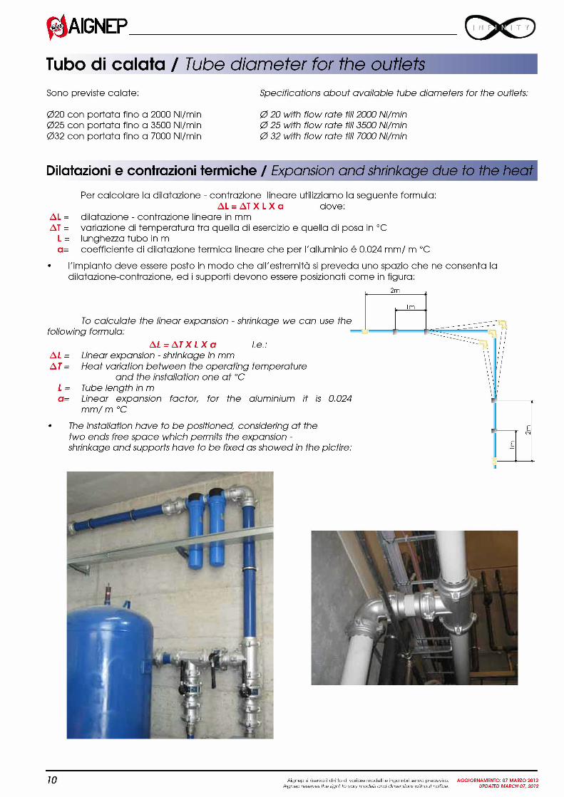
Dilatazioni e contrazioni termiche / Expansion aria shrinkage due to the heat
AL=AT=
L=a=
Per calcolare la dilatazione - contrazione lineare utilizziamo la seguente formula:AL = AT X LX a dove:
dilatazione - contrazione lineare in mmvariazione di temperatura tra quella di esercizio e quella di posa in °Clunghezza tubo in mcoefficiente di dilatazione termica lineare che per l'alluminio é 0.024 mm/ m °C
l'impianto deve essere posto in modo che all'estremitá si preveda uno spazio che ne consenta ladilatazione-contrazione, ed i support devono essere posizionati come in figura:
2m
To calculate the linear expansion - shrinkage we can use thefollowing formula:
AL= A T X L X a i.e.:AL = Linear expansion - shrinkage in mmAT = Heat variation between the operating temperature
and the installation one at °CL = Tube length in ma= Linear expansion factor, for the aluminium it is 0.024
mm/ m °C
• The installation have to be positioned, considering at thetwo ends free space which permits the expansion -shrinkage and supports have to be fixed as showed in the pictire:
10
l m
Specifications about available tube diameters for the outlets:
1,71
Csi
Aignep si riserva ii diritho di variare rnodelli e ingornbri senza preavviso. AGGIORNAMENTO: 07 MARZO 2012Aignep reserves the right to vary models and dimensions without notice. UPDATED MARCH 07, 2012