Embed Size (px)
Citation preview

1 Rev- 3 Dated August 2017
CAR Section II Series X Part IV is proposed to be amended. The propose amendments are shown in subsequent affect paragraphs.
The text of the amendment is arranged to show deleted text, new or amended text as shown below: (a) deleted text is marked with strikethrough; (b) new or amended text is highlighted in grey; (c) an ellipsis (…) indicates that the remaining text is unchanged in front of or following the reflected amendment
Subject: Use of Flammability requirements for furnishing materials to be used in aircraft. 1. INTRODUCTION:
This part of Series 'X' of Civil Airworthiness Aviation Requirements prescribes detailed
requirements related to use of flammability requirements for furnishing materials in
aircraft in its each compartment, occupied by crew or passengers or cargo or
baggage.
2. DEFINITION:
"Self-extinguishing" means that when a flame is applied for a limited period and
removed, the material shall self- extinguish within a specified time, (for details
please refer to Appendix 'F' to F.A.R. Part 25).
"Flame resistant" means not susceptible to combustion to the point of propagating a
flame after ignition source is removed.
3. APPLICABILITY:
The requirements are applicable to normal and acrobatic category aircraft,
excepting those aircraft which have fuselages either covered with wood or fabric.
4. SCOPE:
4.1 It is required that no furnishing material be used in any compartment (crew,
passenger, cargo or baggage) of normal or aerobatic category aircraft in a form in
which it burns readily. The materials of all fittings, furnishings, upholstery, loose
covers, the wall, floor and ceiling linings or acoustic lagging, must be such as to
preclude the possibility of propagation of fire beyond the immediate vicinity of ignition
CIVIL AVIATION REQUIREMENTS SECTION 2 - AIRWORTHINESS SERIES 'X' PART IV 25TH FEBRUARY '1986
2 Rev- 3 Dated August 2017
sources, like lighted cigarettes/matches or electrical short circuits. It is further
emphasized that even passenger baggage restraining/securing equipment like
straps, seat belts must not contribute significantly to the propagation of fire.
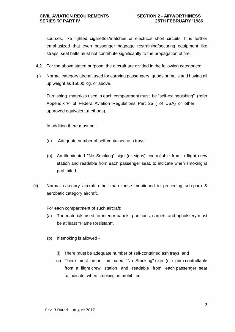
4.2 For the above stated purpose, the aircraft are divided in the following categories:
(i) Normal category aircraft used for carrying passengers, goods or mails and having all
up weight as 15000 Kg. or above.
Furnishing materials used in each compartment must be "self-extinguishing" (refer
Appendix 'F' of Federal Aviation Regulations Part 25 ( of USA) or other
approved equivalent methods).
In addition there must be:-
(a) Adequate number of self-contained ash trays.
(b) An illuminated "No Smoking" sign (or signs) controllable from a flight crew
station and readable from each passenger seat, to indicate when smoking is
prohibited.
(ii) Normal category aircraft other than those mentioned in preceding sub-para &
aerobatic category aircraft.
For each compartment of such aircraft:
(a) The materials used for interior panels, partitions, carpets and upholstery must
be at least "Flame Resistant".
(b) If smoking is allowed -
(i) There must be adequate number of self-contained ash trays; and
(ii) There must be an illuminated "No Smoking" sign (or signs) controllable
from a flight crew station and readable from each passenger seat
to indicate when smoking is prohibited.

CIVIL AVIATION REQUIREMENTS SECTION 2 - AIRWORTHINESS SERIES 'X' PART IV 25TH FEBRUARY '1986
3 Rev- 3 Dated August 2017
(c) If smoking is totally prohibited then instead of (b) above, there must be a placard
to that effect.
4.3 Aircraft seats - resistance to fire:
(i) Applicability:
This requirement is applicable to all seats except seats located within the flight deck,
installed in Indian registered aircraft (aeroplanes and rotorcraft) over 5700 Kg.
MTOW, certificated in the Transport Category (Passenger) of a type for which a Type
Certificate was issued on or after 1 January '1958.
(ii) For those aircraft defined in paragraph 1 already in service or to be introduced into
service, it is required that such aircraft shall be equipped with seats (except seats
located in the flight deck) which comply with the standard given in FAR 25, Appendix
'F', Part II (copy enclosed). The above requirement envisages covering of the seat
cushions with a fire blocker.
Note: Transport Category aircraft are those aircraft which are type certificated to
FAR 25/ JAR 25.
(iii) Compliance:
(a) With effect from 1st November '1987 all affected seats fitted to aircraft defined
in paragraph 1 above shall comply with this requirement.
(b) With effect from 1st July '1986 all aircraft seats newly manufactured and which
are intended for use on aircraft defined in paragraph 1 above shall also comply
with this requirement.
(c) Each seat cushion (squab and back support), except those fitted to seats located
within the flight deck shall meet the requirements of FAR fire test criteria agreed
with DGCA.
5. REQUIREMENTS FOR MAINTENANCE OF FIRE RESISTANCE
The continuance of the flame resisting properties of the furnishing material would
depend upon their use in service and the method used for their cleaning. Incorrect
dry cleaning, laundering or proprietary finishing processes which enhance durability

CIVIL AVIATION REQUIREMENTS SECTION 2 - AIRWORTHINESS SERIES 'X' PART IV 25TH FEBRUARY '1986
4 Rev- 3 Dated August 2017
and minimise soiling may seriously destroy or impair the flame resistant properties.
Also application of one flame retardant process on top of another, of a different type
may have the effect of inhibiting the properties of both processes. During service,
seat covers become contaminated with perspiration which leaves a deposit of body
salts, etc., which may accumulate impairing the flame resistance properties of the
furnishing material. Disinfectants etc., sprayed from aerosol cans in aircraft cabins
may effect the long term flame resistant properties of the furnishing materials. The
operators and maintenance organisations must have an adequate control over the
cleaning of the aircraft furnishing materials. Knowledge of the material type, the
recommended cleaning or proprietary finishing processes methods, the effect of
time in service on the flame resistance properties, the flame retardant processes
applied, if any, and the method of re- application of such process, where this is
necessary are essential.
All the operators/maintenance organisations are advised to carry out sample test of
each batch of furnishing materials for flame resistance in accordance with FAR
25.853 after every dry cleaning. The procedure for cleaning and subsequent
testing shall be detailed in the Quality Control Manual.
6. ADDITIONAL SAFETY PRECAUTIONS:
(i) Each receptacle for towels, paper or waste in toilets of such aircraft shall be
constructed of materials resistant to fire. The receptacles shall incorporate covers
or other provisions for containing possible fire, if started in the receptacle.
(ii) Placards shall be displayed in all toilets compartments at all times, stating that
"Smoking is Prohibited".
(iii) There must be a prescribed number of hand fire extinguishers, conveniently located
in each compartment. as required under the Requirements (See CAR Series "I" Part
II or Section 8, Series O) .
7. This supersedes requirements contained in CAR Series ‘X’ Part IV, Issue I, dated
10th December, 1976.
(B S Bhullar)
Director General of Civil Aviation

CIVIL AVIATION REQUIREMENTS SECTION 2 - AIRWORTHINESS SERIES 'X' PART IV 25TH FEBRUARY '1986
5 Rev- 3 Dated August 2017
A P P E N D I X - 'F' (Part I)
AN ACCEPTABLE TEST PROCEDURE FOR SHOWING COMPLIANCE WITH $$ 33.25.853, 25.855, AND 25.1359)
(a) CONDITIONING:
Specimens must be conditioned to 70 ± 5 F., and at 50 percent ± 5 percent relative
humidity until moisture equilibrium is reached or for 24 hours. Only one specimen at
a time may be removed from the conditioning environment immediately before
subjecting it to the flame. Each specimen must remain in the conditioning
environment until it is subjected to the flame.
(b) SPECIMEN CONFIGURATION:
Except as provided for materials used in electrical wire and cable insulation and in
small parts, materials must be tested either as a section cut from a fabricated part
as installed in the airplane or as a specimen simulating a cut section, such as a
specimen cut from a flat sheet of the material or a model of the fabricated part. The
specimen may be cut from any location in a fabricated part; however fabricated units,
such as sandwich panels, may not be separated for test. The specimen thickness
must be no thicker than the minimum thickness to be qualified for use in the airplane,
except that:
(1) Thick foam parts, such as seat cushions, must be tested in 1/2 inch thickness; (2) When showing compliance with $25.853 (b-3) for materials used in small parts
that must be tested, the materials must be tested in no more than 1/8 inch
thickness;
(3) When showing compliance with 25.1359(d) for materials used in electrical wire
and cable insulation, the wire and cable specimens must be the same size as
used in the airplane. In the case of fabrics, both the warp and fill direction
of the weave must be tested to determine the most critical flammability
condition. When performing the tests prescribed in paragraph (d) through (e) of
(Part I of this Appendix,) the specimen must be mounted in a metal frame so
that;

CIVIL AVIATION REQUIREMENTS SECTION 2 - AIRWORTHINESS SERIES 'X' PART IV 25TH FEBRUARY '1986
6 Rev- 3 Dated August 2017
(i) In the vertical tests of paragraph (d), the two long edges and the upper
edge are held securely;
(ii) In the horizontal test of paragraph (e), the two long edges and the edge
away from the flame are held securely;
(iii) The exposed area of the specimen is at least 2 inches wide and 12 inches
long, unless the actual size used in the airplane is smaller; and
(iv) The edge to which the burner flame is applied must not consist of the
finished or protected edge of the specimen but must be representative of
the actual cross-section of the material or part installed in the airplane.
When performing the test prescribed in paragraph (f) of (part I of this
securely and the exposed area of Appendix), the specimen must be
mounted in a metal frame so that all four edges are held the specimen is
at least 2 inches by 8 inches.
(c) APPARATUS:
Except as provided in paragraph (g) (Part I of this Appendix) tests must be
conducted in a draft- free cabinet in accordance with Federal Test Method Standard
191 Method 5903 (revised Method 5902) for the vertical test, or Method 5906 for
horizontal test (available from the General Services Administration, Business
Service Centre, Region 3, Seventh & D Streets, S.W., Washington, D.C. 20407)
or other approved equivalent methods. Specimens which are too large for the
cabinet must be tested in similar draft-free conditions.
(d) VERTICAL TEST:
In compliance with $25.853(a) and (b).} A minimum of three specimens must be
tested and the results averaged. For fabrics, the direction of weave corresponding
to the most critical flammability conditions must be parallel to the longest dimension.
Each specimen must be supported vertically. The specimen must be exposed to
a Bunsen or Tirrill burner with a nominal 3/8 inch I.D. tube adjusted to give a flame
of 1-1/2 inches in height. The minimum flame temperature measured by a calibrated
thermocouple pyrometer in the centre of the flame must be thee fourths inch above
the top edge of the burner. The flame must be applied to the centerline of the lower
edge of the specimen. For materials covered by $25.853 (a), the flame must be
applied for 60 seconds and then removed. For materials covered by $25.853(b),

CIVIL AVIATION REQUIREMENTS SECTION 2 - AIRWORTHINESS SERIES 'X' PART IV 25TH FEBRUARY '1986
7 Rev- 3 Dated August 2017
the flame must be applied for 12 seconds and then removed. Flame time, burn
length, and flaming time of drippings, if any, must a recorded. The burn length
determined in accordance with paragraph (h) of (Part I of this Appendix) must be
measured to the nearest one-tenth inch.
(e) HORIZONTAL TEST IN COMPLIANCE WITH $ 25.853(b-2) AND (b-3):
A minimum of three specimens must be tested and the results averaged. Each
specimen must be supported horizontally. The exposed surface when installed in
the aircraft must be face down for the test. The specimen must be exposed to a
Bunsen burner or Tirrill burner with a nominal 3/8 inch I.D. Tube adjusted to give a
flame of 1-1/2 inches in height. The minimum flame temperature measured by a
calibrated thermocouple pyrometer in the centre of the flame must be 1550 degree
F. The specimen must be positioned so that the edge being tested is three fourths
of an inch above the top of, and on the centre line, the burner. The flame must be
applied for 15 seconds and then removed. A minimum of 10 inches of the specimen
must be used for timing purpose, approximately 1- 1/2 must burn before the burning
front reaches the timing zone, and the average burn rate must be recorded.
(f) FORTY-FIVE DEGREE TEST IN COMPLIANCE WITH $ 25.855 (A-1):
A minimum of three specimens must be tested and the results averaged. The
specimens must be supported at an angle of 45 degree to a horizontal surface. The
exposed surface when installed in the aircraft must be face down for the test. See
FAR. The minimum flame temperature measured by a calibrated thermocouple
pyrometer in the centre of the flame must be 1550 degree F. Suitable precautions
must be taken to avoid drafts. One-third of the flame must contact the materials at
the centre of the specimen and must be applied for 30 seconds and then removed.
Flame time, glow time, and whether the flame penetrates (passes through) the
specimen must be recorded.
(g) SIXTY DEGREE TEST IN COMPLIANCE WITH $ 25.1359(d):
A minimum of three specimens of each wire specification (make and size) must be
tested. The specimen of wire or cable (including insulation) must be placed at an
angle of 60 degree with the horizontal to the cabinet specified in paragraph (c)
Part I of this Appendix with the cabinet door open during the test or must be placed
within a chamber approximately 2 feet high x 1 foot x 1 foot, open at the top and at
one vertical side (front), and which allows sufficient flow of air for complete
CIVIL AVIATION REQUIREMENTS SECTION 2 - AIRWORTHINESS SERIES 'X' PART IV 25TH FEBRUARY '1986
8 Rev- 3 Dated August 2017
combustion, but which is free from drafts. The specimen must be parallel to and
approximately 6 inches from the front of the chamber. The lower end of the
specimen must be held rigidly clamped. The upper end of the specimen must pass
over a pulley or rod and must have an appropriate weight attached to it so that the
specimen is held tautly throughout the flammability test. The test specimen span
between lower clamp and upper pulley or rod must be 24 inches and must be marked
8 inches from the lower end to indicate the central point for flame application. A
flame from a Bunsen or Tirrill burner must be applied for 30 seconds at the test mark.
The burner must be counted underneath the test mark on the specimen,
perpendicular to the specimen and at an angle of 30 degree to the vertical plane of
the specimen. The burner must have a nominal bore of 3/8 inch, and must be
adjusted to provide a 3-inch high flame with an inner cone approximately one-third
of the flame height. The minimum temperature of the hottest portion of the flame, as
measured with a calibrated thermocouple pyrometer, may not be less than 1750
degree F. The burner must be positioned so that the hottest portion of the flame is
applied to the test mark on the wire. Flame time, burn length, and flaming time of
drippings, if any must be recorded. The burn length determined in accordance with
paragraph (h) Part I of this Appendix must be measured to the nearest 1/10-inch.
Breaking of the wire specimens is not considered a failure.
(h) BURN LENGTH:
Burn length is the distance from the original edge to the farthest evidence of
damage to the test specimen due to flame impingement, including areas of partial
or complete consumption, charring, or embrittlement, but not including areas
sooted, stained, warped, or discolored, nor areas where material has shrunk or
melted away from the heat source.

CIVIL AVIATION REQUIREMENTS SECTION 2 - AIRWORTHINESS SERIES 'X' PART IV 25TH FEBRUARY '1986
9 Rev- 3 Dated August 2017
PART II
FLAMMABILITY OF SEAT CUSHIONS _____________________________
(a) CRITERIA FOR ACCEPTANCE: Each seat cushion must meet the following criteria:
(1) At least, three sets of seat bottom and seat back cushion specimens must be tested.
(2) If the cushion is constructed with a fire blocking material, the fire blocking material
must completely enclose the cushion foam core material.
(3) Each specimen tested must be fabricated using the principal components (i.e. foam,
core, flotation materials, fire blocking material, if used, and dress covering) and
assembly processes (representative seams and closures) intended for use in the
production articles. If a different material combination is used for the back cushion
than for the bottom cushion, both material combinations must be tested as
complete specimen sets, each set consisting of a back cushion specimen and a
bottom cushion specimen. If a cushion including outer dress covering, is
demonstrated to meet the requirements of this Appendix using the oil burner test,
the dress covering of that cushion may be replaced with a similar dress covering
provided the burn length of the replacement covering, as determined by the test
specified in $25.853(b), does not exceed the corresponding burn length of the
dress covering used on the cushion subjected to the oil burner test.
(4) For at least two-thirds of the total number of specimen sets tested, the burn length
from the burner must not reach the side of the cushion opposite the burner. The burn
length must not exceed 17 inches. Burn length is the perpendicular distance from
the inside edge of the seat frame closest to the burner to the farthest evidence
of damage to the test specimen due to flame impingement, including areas of
partial or complete consumption, charring, or embrittlement, but not including
areas sooted, stained, warped, or discolored, or areas where material has shrunk or
melted away from the heat source.
CIVIL AVIATION REQUIREMENTS SECTION 2 - AIRWORTHINESS SERIES 'X' PART IV 25TH FEBRUARY '1986
10 Rev- 3 Dated August 2017
(5) The average percentage weight loss must not exceed 10 percent. Also, at least two-
thirds of the total number of specimen sets tested must not exceed 10 percent
weight loss all droppings falling from the cushion and mounting stand are to be
discarded before the after- test weight is determined. The percentage weight loss
for a specimen set is the weight of the specimen set before testing less the weight of
the specimen set after testing expressed as the percentage of the weight before
testing.
(b) TEST CONDITIONS:
Vertical air velocity should average 25 fpm ±10 fpm at the top of the back seat
cushion. Horizontal air velocity should be below 10 fpm just above the bottom seat
cushion. Air velocities should be measured with the ventilation hood operating and
the burner motor off.
(c) TEST SPECIMENS:
(1) For each test, one set of cushion specimens representing a seat bottom and seat
back cushion specimen must be used.
(2) The seat bottom cushion specimen must be 18 ± 1/8 inches (457 ± 3 mm) wide by
20 ± 1/8 inches (508 ± 3 mm) deep by 4 ± 1/8 inches (102 ± 3 mm) thick, exclusive
fabric closures and seam overlap.
(3) The seat back cushion specimen must be 18 ± 1/8 inches (432 ± 3 mm) wide by 25
± 1/8 inches (635 ± 3 mm) high by 2 ± 1/8 inches (51 ± 3 mm) thick, exclusive of
fabric closures and seam overlap.
(4) The specimens must be conditioned at 70 ± 5 º F (21 ± 2 ºC.) 55% ± 10% relative
humidity for at least 24 hours before testing.
(d) TEST APPARATUS:
The arrangement of the test apparatus is shown in Figures 1 through 5 and must
include the components described in this section. Minor details of the apparatus may
vary, depending on the model of burner used.
(1) SPECIMEN MOUNTING STAND:
The mounting stand for the test specimens consists of steel angles, as shown in
Figure 1. The length of the mounting stand legs is 12 ± 1/8 inches (305 ± 3 mm).

CIVIL AVIATION REQUIREMENTS SECTION 2 - AIRWORTHINESS SERIES 'X' PART IV 25TH FEBRUARY '1986
11 Rev- 3 Dated August 2017
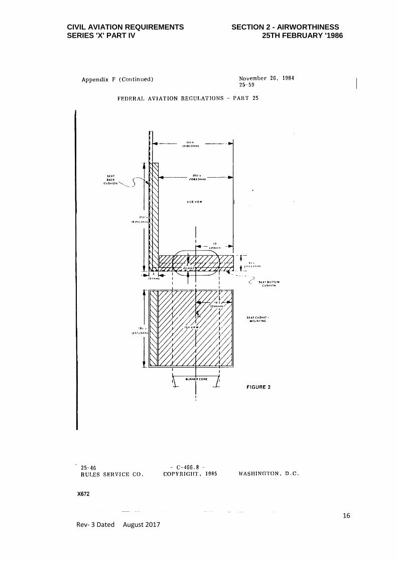
The mounting stand must be used for mounting the test specimen seat bottom and
seat back, as shown in figure 2. The mounting stand should also include a suitable
drip pan lined with aluminium foil, dull side up.
(2) TEST BURNER: The burner to be used in testing must:-
(i) Be modified gun type;
(ii) Have an 80 degree spray angle nozzle nominally rated for 2.25 gallons/hour at 100
psi.
(iii) Have a 12 inch (305 mm) burner cone installed at the end of the draft tube, with an
opening 6 inches (152 mm) high and 11 inches (280 mm) wide, as shown in Figure
3; and
(iv) Have a burner fuel pressure regulator that is adjusted to deliver a nominal 2.0
gallon/hour of # 2 Grade kerosene or equivalent required for the test.
Burner models which have been used successfully in testing are the Lennox Model
OB-32, Carlin Model 200 CRD, and Park Model DPL 3400. FAA published reports
pertinent to this type of burner are: (1) Power plant Engineering Report No. 3A,
Standard Fire Test Apparatus and Procedure for Flexible Hose Assemblies, dated
March 1978; and (2) Report No. DOT/FAA/RD/76/213, Reevaluation of Burner
Characteristics for Fire Resistance Tests, dated January, 1977.
(3) CALORIMETER:
(i) The calorimeter to be used in testing must be a (0-15.0 BTU/ft 2-sec. 0-17.0 w/cm2 )
calorimeter, accurate ± 3%, mounted in a 6 inch by 12 inch (152 by 305 mm) by 3/4
inch (19 mm) thick calcium silicate insulating board which is attached to a steel
angle bracket for placement in the test stand during burner calibration, as shown in
Figure 4.
(ii) Because crumbling of the insulating board with service can result in misalignment
of the calorimeter, the calorimeter must be monitored and the mounting shimmed,
as necessary, to ensure that the calorimeter face is flush with the exposed plane of
the insulating board in a plane parallel to the exit of the test burner cone.
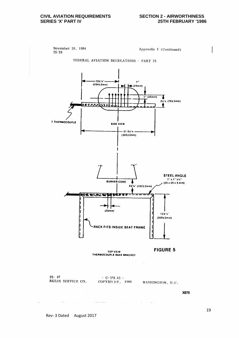
(4) THERMOCOUPLES:

CIVIL AVIATION REQUIREMENTS SECTION 2 - AIRWORTHINESS SERIES 'X' PART IV 25TH FEBRUARY '1986
12 Rev- 3 Dated August 2017
The seven thermocouples to be used for testing must be 1/16 to 1/8 inch metal
sheathed, ceramic packed, type K, grounded thermocouples with a nominal 22 to 30
American wire gage (AWG) size conductor. The seven thermocouples must be
attached to a steel angle bracket to form a thermocouple rake for placement in the
test stand during burner calibration, as shown in Figure 5.
(5) APPARATUS ARRANGEMENT:
The test burner must be mounted on a suitable stand to position the exit of the
burner cone a distance of 4 ± 1/8 inches (102 ± 3 mm) from one side of the
specimen mounting stand. The burner stand should have the capability of allowing
the burner to be swung away from the specimen mounting stand during warmup
periods.
(6) DATA RECORDING:
A recording potentiometer or other suitable calibrated instrument with an appropriate
range must be used to measure and record the outputs of the calorimeter and the
thermocouples.
(7) WEIGHT SCALE:
Weighing device - A device must be used that with proper procedures may
determine the before and after test weights of each set of seat cushion specimens
within 0.02 pounds ( 9 grams). A continuous weighing system is preferred.
(8) TIMING DEVICE:
A stopwatch or other device (calibrated to ±1 second) must be used to measure the
time of application of the burner flame and self-extinguishing time or test duration.
(e) PREPARATION OF APPARATUS:
Before calibration, all equipment must be turned on and the burner fuel must be
adjusted as specified in paragraph. (d)(2).
(f) CALIBRATION:
To ensure the proper thermal output of the burner, the following test must be made:-

CIVIL AVIATION REQUIREMENTS SECTION 2 - AIRWORTHINESS SERIES 'X' PART IV 25TH FEBRUARY '1986
13 Rev- 3 Dated August 2017
(1) Place the calorimeter on the test stand as shown in Figure 4 at a distance of 4 ±
1/8 inches (102 plus minus 3 mm) from the exit of the burner cone.
(2) Turn on the burner, allow it to run for 2 minutes for warmup, and adjust the burner
air intake damper to produce a reading of 10.5 ± 0.5 BTU/ft2- sec.(11.9 plus
minus 0.6 w/cm2 ) on the calorimeter to ensure steady state conditions have been
achieved. Turn off the burner.
(3) Replace the calorimeter with the thermocouple rake (Figure 5).
(4) Turn on the burner and ensure that the thermocouples are reading 1900 ± 100 ºF
(1038 ± 38 ºC) to ensure steady state conditions have been achieved.
(5) If the calorimeter and thermocouples do not read within range, repeat steps in
paragraphs 1 through 4 and adjust the burner air intake damper until the proper
readings are obtained. The thermocouples rake and the calorimeter should be used
frequently to maintain and record calibrated test parameters. Until the specific
apparatus has demonstrated consistency, each test should be calibrated. After
consistency has been confirmed, several tests may be conducted with the pre-test
calibration before and a calibration check after the series.
(g) TEST PROCEDURE:
The flammability of each set of specimens must be tested as follows:
(1) Record the weight of each set of seat bottom and seat back cushion specimens to
be tested to the nearest 0.02 pound (9 grams).
(2) Mount the seat bottom and seat back cushion test specimens on the test stand
as shown in Figure 2, securing the seat back cushion specimen to the test stand
at the top.
(3) Swing the burner into position and ensure that the distance from the exit of the burner
cone to the side of the seat bottom cushion specimen is 4 ± 1/8 inches (102 ± 3 mm).
(4) Swing the burner away from the test position. Turn on the burner and allow it to run
for 2 minutes to provide adequate warmup of the burner cone and flame stabilization.
(5) To begin the test, swing the burner into the test position and simultaneously start the
timing device.

CIVIL AVIATION REQUIREMENTS SECTION 2 - AIRWORTHINESS SERIES 'X' PART IV 25TH FEBRUARY '1986
14 Rev- 3 Dated August 2017
(6) Expose the seat bottom cushion specimen to the burner flame for 2 minutes and then
turn off the burner. Immediately swing the burner away from the test position.
Terminate test 7 minutes after initiating cushion exposure to the flame by use of a
gaseous extinguishing agent (i.e. Halon or Carbon dioxide).
(7) Determine the weight of the remains of the seat cushion specimen set left on the
mounting stand to the nearest 0.02 pound (9 grams) excluding all droppings.
(h) TEST REPORT:
With respect to all specimen sets tested for a particular seat cushion for which testing
of compliance is performed, the following information must be recorded:
(1) An identification and description of the specimens being tested.
(2) The number of specimen sets tested.
(3) The initial weight and residual weight of each set, the calculated percentage weight
loss of each set, and the calculated average percentage weight loss for the total
number of sets tested.
(4) The burn length for each set tested.

CIVIL AVIATION REQUIREMENTS SECTION 2 - AIRWORTHINESS SERIES 'X' PART IV 25TH FEBRUARY '1986
15 Rev- 3 Dated August 2017
CIVIL AVIATION REQUIREMENTS SECTION 2 - AIRWORTHINESS SERIES 'X' PART IV 25TH FEBRUARY '1986
16 Rev- 3 Dated August 2017

CIVIL AVIATION REQUIREMENTS SECTION 2 - AIRWORTHINESS SERIES 'X' PART IV 25TH FEBRUARY '1986
17 Rev- 3 Dated August 2017

CIVIL AVIATION REQUIREMENTS SECTION 2 - AIRWORTHINESS SERIES 'X' PART IV 25TH FEBRUARY '1986
18 Rev- 3 Dated August 2017
CIVIL AVIATION REQUIREMENTS SECTION 2 - AIRWORTHINESS SERIES 'X' PART IV 25TH FEBRUARY '1986
19 Rev- 3 Dated August 2017