Embed Size (px)
Citation preview

Gas phase ion-ion recombination and electron capture reactions at atmospheric pressureby John Allen Culbertson
A thesis submitted in partial fulfillment of the requirements for the degree of Doctor of Philosophy inChemistryMontana State University© Copyright by John Allen Culbertson (1995)
Abstract:Gas phase ion processes at high pressure (one atmosphere) are the basis of some of the most sensitiveand selective analytical techniques for chemical analysis, ie. the electron capture detector (BCD), theatmospheric pressure ionization mass spectrometer (APIMS) , and the ion mobility spectrometer.Under most conditions, ion-ion recombination (IIR) will be the dominant loss mechanism for ions inhigh pressure ionized gases. Therefore, it is of fundamental importance to understand IIR. In this thesiswork, relative IIR rate constants were determined using an APIMS. Also, a new method was developedfor the determination of the fate of molecular anions upon recombination with positive ions atatmospheric pressure. These results were used to predict the atmospheric chemistry of certainperfluorocompounds (PFC's). This method also proved to be effective for determining the electroncapture (EC) rate constants of compounds that undergo dissociative EC.
The APIMS showed that for all ions studied, the IIR rate constant was the same, approximately 2 x10^-6 cm^3 sec^-1. The experimental apparatus developed for the determination of the fate ofmolecular anion upon IIR allowed for the comparison of two BCD responses for the compound beingstudied. The first was a normal BCD response. The second BCD response was obtained after the gaschromatographic carrier gas was passed through a reaction cell in which EC and IIR reactions occurred.The ratio of these two responses was interpreted in terms of the extent to which the molecule was lostto EC and then regenerated by IIR. The conclusions were that the molecular anions of C7F14(perfluoromethylcyclohexane) and C6F12 (perfluorodimethylcyclobutane) regenerate their parentneutrals upon IIR while the molecular anion of SF6 does not. The molecular anions of nitrobenzeneand several substituted nitrobenzenes were also studied and showed varying extents of regeneration.The same experimental procedure was also used to determine EC rate constants for compounds thatcould not be regenerated by IIR.

GAS PHASE ION-ION RECOMBINATION AND ELECTRON
CAPTURE REACTIONS AT ATMOSPHERIC PRESSURE
by
John Allen Culbertson
A thesis submitted in partial fulfillment of the requirements for the degree
of
Doctor of Philosophy
in
Chemistry
MONTANA STATE UNIVERSITY Bozeman, Montana
October 1995

JD312CWrTX ii
APPROVAL
of a thesis submitted by
John Allen Culbertson
This thesis has been read by each member of the thesis committee and has been found to be satisfactory regarding content, English usage, format, citations, bibliographic style, and consistency, and is ready for submission to the College of Graduate Studies.
/0Date
Approved for the Major Department
Hefad, Major Department
Approved for the College of Graduate Studies
Z! %Graduate DeanDate
iii
STATEMENT OF PERMISSION TO USE
In presenting this thesis in partial fulfillment of the
requirements for a doctoral degree at Montana State
University, I agree that the Library shall make it available
to borrowers under rules of the Library. I further agree that
copying of this thesis is allowable only for scholarly
purposes, consistent with "fair use" as prescribed in the U.S.
Copyright Law. Requests for extensive copying or reproduction
of this thesis should be referred to University Microfilms
International, 300 North Zeeb Road, Ann Arbor, Michigan 48106,
to whom I have granted "the exclusive right to reproduce and
distribute my dissertation in and from microfilm along with
the non-exclusive right to reproduce and distribute my
abstract in any format in whole or in part."
Date /%?-

iv
TABLE OF CONTENTS
Page
INTRODUCTION ........................... I
Gas Phase Ion C h e m i s t r y ..................................... IElectron Capture .................................... 3Ion-Ion Recombination ............................. 4
Atmospheric Fates of Perfluoro Compounds ............. 5
THEORY ....................................................... 9
Chemistry and Dynamics Within theReaction Cell/ECD ......................................... 9
V e n t i l a t i o n ...........................................13D i f f u s i o n .............................................14
Ion-Ion Recombination.................... 16Ter-Molecular Ion-Ion Recombination ............. 18
E X P E R I M E N T A L ........... 22
The Reaction/Dummy Cell Apparatus ....................... 22The Reactidn/Dummy Cell .............................23Sample Preparation and Introduction ............. 25Detection of Compounds ............................. 27
The Dual Cell E C D .......................................... 29The Atmospheric Pressure IonizationMass Spectrometer.......................•................ 31
Major Components of the A P I M S ...................... 33Sample Introduction ................................ 34
RESULTS AND D I S C U S S I O N ................................. 35
Relative Ion-Ion RecombinationRate Constants .............................................35
Positive Ions ........................................ 37Negative Ions ........................................ 42Interpretation of Data for RelativeIIR Rate Constants '....................................43

V
TABLE OF CONTENTS-Corrtinued
Page
Fate of Selected Molecular Anions UponRecombination with Positive I o n s ........................ 45
Treatment of the D a t a ............................... 47Measurement of EC Rate Constantsat Atmospheric Pressure ........................... 52X Values for SF6, C7F147 and C6F1 2 ....................54
Effect of Positive Ions onIIR Fate of SF6" and C7F14" ........................ 67On the Differing Fates of SF6",C7F14", and C6F12" ....................................70Implications for the AtmosphericChemistry of SF6, C7F14, and C6F1 2 ................. 73
X Values for Nitrobenzene and SeveralSubstituted Nitrobenzenes ......................... 74
EC Rate Constants for DissociativelyAttaching Compounds ....................................... 76
S U M M A R Y ........................................................ 84
LITERATURE CITED ........................................... 90
".'h-

LIST OF TABLES
Table Page
1. APIMS total positive ion signal during the introduction of electron attaching compounds . . . 44
2. Summary of results for SF6, C7F14, and C6F12with CF2Br2 and CHCl3 as method checks ............... 55
3 . Values of ex and x at 180°C with the additionof trimethylamine to the carrier gas ................ 68
4. Summary of results for nitrobenzenes at 120°C .-. 74
5. EC rate constants for dissociatively attaching compounds as determined by the reaction/dummycell a p p a r a t u s ........................................ 77

VU
LIST OF FIGURES
Figure Page
I. Plot of ion-ion recombination rate constantversus p r e s s u r e .................. .................. 17
2. Schematic of reaction/dummy cell apparatus . . . . 22
3. Reaction/dummy cell b l o c k ......................... 24
4. The dual cell E C D .................... ' ............30
5. The Atmospheric Pressure IonizationMass s p e c t r o m e t e r .................................. 32
6. API mass spectrum of triethylamine at 120°C in nitrogen buffer gas shortly after l/xl wasinjected into the d i l u t o r .........................3 9
7. API mass spectrum of triethylamine.approximatelytwo hours after it was injected into the dilutor . 40
8. API positive ion background mass spectrum . . . . 41
9. Typical GC-ECD analysis of a gas sample containing about 1 .5 ppb CFCl3 and 1 .0 ppb C7F14 in nitrogen obtained with the reaction/dummy cell apparatusat 1 2 0 ° C ............................................... 49
10. API mass spectrum of SF6 at 120°C in nitrogenbuffer g a s .............................................59
11. API mass spectrum of C7F14 at 120°C in nitrogenbuffer gas ................................. 60
12. API mass spectrum of C6F12 at 30°C in nitrogenbuffer g a s ............................................. 63

VUl
LIST OF FIGURES-Continued
Figure Page
13 . API mass spectrum of C6F12 at 75°C in nitrogenbuffer g a s ............................................. 64
14. API mass spectrum of C6F12 at 120°C in nitrogenbuffer g a s .......................... 65
15. API mass spectrum of C6F12 at 180°C in nitrogenbuffer g a s ............................................. 66

IX
ABSTRACT
Gas phase ion processes at high pressure (one atmosphere) are the basis of some of the most sensitive and selective analytical techniques for chemical analysis, ie. the electron capture detector (BCD), the atmospheric pressure ionization mass spectrometer (APIMS) , and the ion mobility spectrometer. Under most conditions, ion-ion recombination (HR) will be the dominant loss mechanism for ions in high pressure ionized gases. Therefore, it is of fundamental importance to understand H R . In this thesis work, relative IIR rate constants were determined using an APIMS. Also, a new method was developed for the determination of the fate of molecular anions upon recombination with positive ions at atmospheric pressure. These results were used to predict the atmospheric chemistry of certain perfluorocompounds ( P F C s ) . This method also proved to be effective for determining the electron capture (EC) rate constants of compounds that undergo dissociative EC.
The APIMS showed that for all ions studied, the IIR rate constant was the same, approximately 2 x 10'® cm3 sec'"1. The experimental apparatus developed for the determination of the fate of molecular anion upon IIR allowed for the comparison of two ECD responses for the compound being studied. The first was a normal ECD response. The second ECD response was obtained after the gas chromatographic carrier gas was passed through a reaction cell in which EC and IIR reactions occurred. The ratio of these two responses was interpreted in terms of the extent to which the molecule was lost to EC and then regenerated by H R . The conclusions were that the molecular anions of C7F14 (perfluoromethylcyclohexane) and C6F12 (perfluorodimethylcyclobutane) regenerate their parent neutrals upon IIR while the molecular anion of SF6 does not. The molecular anions of nitrobenzene and several substituted nitrobenzenes were also studied and showed varying extents of regeneration. The same experimental procedure was also used to determine EC rate constants for compounds that could not be regenerated by H R .
I
INTRODUCTION
Gas Phase Ion Chemistry
During the past 25 years, gas phase ion chemistry (GPIC)
has been a steadily growing research field (I),(2),(3). This
is due in part to the fact that the intrinsic properties of
ions and molecules are best studied in the gas phase, where
solvent effects can be eliminated or carefully controlled.
Also, some of the most selective and sensitive analytical
techniques for chemical analysis are based upon GPIC. Such
techniques include ion cyclotron resonance (ICR) mass
spectrometry (MS) (4) , chemical ionization (Cl) MS (5) ,
electron capture detection (ECD) (6), atmospheric pressure
ionization (API) MS (7), ion mobility spectrometry (IMS) (8),
and electrospray MS (9) . These techniques operate over a wide
pressure range, from ICT5-IO"6 Torr for ICR, to 0.1 - 0.5 Torr
for CIMS, to atmospheric pressure for BCD, APIMS, IMS, and
electrospray MS. In spite of this wide pressure range, most of
the instrumentation used to study the fundamentals of GPIC
operate at less than 10 Torr. Such instruments typically
employ a mass spectrometer to select and measure the ions of

2
interest. These MS-based instruments include ICR, flowing
afterglow (10), selected ion flow tube (10), and pulsed
electron high pressure MS (11), all of which have contributed
significantly to the wealth of valuable GPIC information that
exists at lower pressures. In contrast, studies of GPIC at
pressures greater than 10 Torr are very few, due mainly to the
lack of capable instrumentation in the past. However, there is
a clear need to understand high pressure GPIC processes in
order to increase the performance of analytical instruments
that operate at or near atmospheric pressure (such as the ones
listed above), thoroughly interpret the results obtained from
such instruments, or to design new high pressure
instrumentation. In addition, gas phase processes at low
pressure are often significantly different from those at high
pressure. Thus, predictions of GPIC at high pressure based on
low pressure results often fail. This basic lack of knowledge
of high pressure gas phase processes was the motivation for
this thesis work. Two processes in particular, ion-ion
recombination (HR) and electron capture (EC), are the focus
of this work and are discussed below.

3
Electron Capture
Several of the most selective and sensitive techniques
for chemical analysis are .based on the electron capture
process. The most widely used of these, and the one used for
a great deal of this thesis work, is the electron capture
detector. The first description of the ECD was by Lovelock
(12) in 1960. While the modern ECD is quite different from the
first ones described by Lovelock, the fundamental
characteristics are similar.
The ECD is very selective in that only molecules with
positive electron affinities and sufficiently large electron
capture cross sections are detected, which comprise a small
minority of compounds. A molecule meeting these criteria may
attach a low energy electron to form a molecular anion
(resonance capture) or a fragment anion (dissociative capture)
The mechanism of the electron capture process is discussed in
the Theory section.
The ECD response is based on changes in the electron
population within the detector. In most BCD's, electrons are
collected at an anode that is pulsed at approximately +50
volts. The resulting current is then measured and maintained

4
at some fixed value by adjusting the pulse frequency, thus the
term, constant current ECD is used. When a compound that
attaches electrons enters, the detector, the electron
population decreases, causing an increase in the pulse
frequency. The response at the chart recorder is proportional
to the change in pulse frequency. In other BCD's, such as the
dual cell ECD used in this work, the anode is pulsed at a
fixed frequency. Thus, a change in electron population results
in a change in the current measured at the anode. This type of
ECD is well suited for fundamental studies in that the
dynamics of the ECD can be changed by adjusting the pulse
frequency and/or pulse width.
Ion-Ion Recombination
The dominant loss mechanism for ions in most high
pressure ionized gases is ion-ion recombination. Diffusion of
ions to grounded surfaces or removal by carrier gas flow is
typically much slower than IIR (13). For this reason, IIR is
a very important reaction within the ECD, and the products of
the IIR reaction may influence the ECD response to certain
compounds.
Consider the following reaction sequence which can occur

within the ECD.
: 5
M + e -* M" (I)
+ neutrals (2a)M-
+ neutrals (2b)
Reaction I is resonance electron capture ' by which the
molecular anion, M", is formed. Reactions 2a/b represent the
two possible pathways of the subsequent IIR between the
molecular anion and positive ions. In reaction 2a, IIR results
in the regeneration of the parent molecule, M, while in
reaction 2b the parent molecular entity has been altered upon
IIR. If the parent molecule is regenerated, it may undergo
additional EC/IIR reactions. This will result in an enhanced
response to that compound relative to the case in which
altered neutrals are formed upon IIR (Reaction 2b) . This type
of behavior can give anomalous responses in gas phase
coulometry (14) experiments and may also have important
implications to the atmospheric chemistry of perfluorinated
compounds (15), which is discussed below.
Atmospheric Fates of Perfluoro Compounds
Fully fluorinated compounds (perfluoro compounds or
PFC's) represent a class of chemicals which include many

6
species that exhibit extreme inertness to chemical and
photochemical reactions. This results in most P F C s being
immune to the processes that typically remove trace chemicals
from the atmosphere, ie., photodissociation and reaction with
radicals (15). Therefore, P F C s may be transported through
the troposphere (the first 15 km of the atmosphere) and
stratosphere (15 to 50 km), to the mesosphere (50 to 90 km).
Only in the mesosphere are important destructive processes for
P F C s thought to exist. These destructive processes include
absorption of Lyman-a radiation (121.6 nm) and reaction with
free electrons. The latter means of destruction can
potentially be more important than photolytic destruction for
those PFC1s that have relatively large EC rate constants.
These EC active compounds are known to include SF6 (16), C-C4F8
(15), and larger cyclic carbon based PFC's, such as C7F14
(perfluoromet hyI cyclohexane) (17), and C10 F18
(perfluorodecaline) (18). Furthermore, it is known that these
molecules capture thermalized electrons primarily by the
resonance EC process (Reaction I) in which the molecular anion
is formed. Therefore, in determining the atmospheric chemistry
of these EC active PFC's, the critical question is: what will
be the neutral products formed in the subsequent recombination

7
of these molecular anions with positive ions, as represented
in Reactions 2a/b. If the original molecule is simply-
regenerated in these IIR reactions, as in pathway 2a, the
sequential EC/IIR reactions will have no impact on the overall
atmospheric chemistry of that compound. If, on the other hand,
the molecular entity is altered by the IIR reaction, as shown
in pathway 2b, the atmospheric presence of that compound will
be terminated by its EC reaction.
Because P F C s are not believed to destroy stratospheric
ozone, they were considered environmentally friendly, and some
were thus suggested as replacements for the ozone depleting
chlorofluoro compounds (15). However, P F C s are expected to
have extraordinarily long atmospheric lifetimes (on the order
of millennia) due to their chemical and photolytic inertness,
and thus significant global warming potentials (GWP) (15). The
GWP is a measure of the relative efficiency of a gas to
contribute to global warming (the greenhouse effect) by
absorption of infrared radiation, per kilogram emitted (15) .
Therefore, even if relatively small amounts of P F C s are
emitted into the Earth's atmosphere, they would accumulate
over time and their impact could be very significant in future
years.

8
Morris et a l . (15) have predicted that for some P F C s
which attach electrons rapidly, the EC/IIR process could
account for at least 90% of their removal in the mesosphere if
the molecule is, in fact, destroyed by its sequence of EC and
IIR reactions. Based on this fact, it is clear that the need
to know whether or not a PFC is regenerated upon HR, as in
Reaction 2a, is of central importance. Therefore, this thesis
will focus on the fractional regeneration of several P F C s
upon IIR at near atmospheric pressure. Work was also performed
to determine what effects the nature of the recombining ions
has on the rate constant for H R . The same experimental
apparatus used for determining the fractional regeneration of
P F C s was also proven to be a very effective method for
determining EC rate constants for dissociatively attaching
compounds. EC rate constant for many such compounds were
determined for the first time in an atmospheric pressure
buffer gas.

9
THEORY
Chemistry and Dynamics Within the
Reaction Cell/ECD
As was mentioned in the Introduction, the chemistry and
dynamics of gas phase processes at or near atmospheric
pressure are quite different from those at low pressure.
Therefore, in order to characterize the reaction cell/ECD
apparatus, these processes must be understood.
The increased gas density at atmospheric pressure results
in a shorter mean free path and therefore a greater collision
frequency, f, between molecules. This is the fundamental
difference between the high and low pressure regimes. A value
for f can be obtained at any given pressure by Equation 3,
. f = vaV2^ (3)
where v is the relative mean velocity of the molecule, o is
the collision cross section,, and N/V is the gas number
density. A value for o can be obtained from a=nd2 where d is
the collision diameter of the molecule (19) . For N2 (d

10
3.7xl0-lom) (19) at 640 Torr and 120°C, f = 5.2 x IO9 sec -1.
However, in the low pressure regime where techniques such as
PHPMS and ICR are often employed to study GPIC, collision
frequencies are much smaller. For example, in an ICR cell
operating at IO"5 torr, f is approximately 100 sec-1.
The high collision frequency at atmospheric pressure
serves to stabilize any excited ions or molecules that are
within the cell and quickly bring them to thermal equilibrium
with the buffer gas. This is important because species with
excess internal energy are often formed from the ionization
process or other energetic reactions. Under most experimental
conditions encountered at atmospheric pressure, any excited
species will be thermalized in 10 collisions and a Maxwell-
Boltzmann energy distribution will be achieved in about 100
collisions with the buffer gas (20).
All chemistry occurring in the reaction cell is initiated
by Reaction 4, in which a beta particle, |3, from a 63Ni foil
Buffer gas + (3 -> Pt + e (4)
collides with a buffer gas molecule to produce a positive ion,
P+, and a secondary electron. The average kinetic energy of
the beta particle is 17 keV (13) and approximately 35 eV is
required to produce one P+/e pair (21), therefore, 458 P+/e

11
pairs are . formed per beta. The secondary electrons are
thermalized by subsequent collisions with the buffer gas. The
rate of change in positive ion or electron concentration in
the cell with no sample present is given by Equation 5 (22),
dne _ dn+ dt dt
SV -Rn n (5)
where ne and n+ are the electron and positive ion densities
respectively, S is the production rate of electrons governed
by the activity of the 63Ni foil, R is the positive ion-
electron recombination rate constant, and V is the volume of
the cell. Applying the steady state assumption to Equation 5,
the equilibrium concentration for ne and n+ can be calculated
from Equation 6.
ne = n* (6)
With a volume of 1.5 cm3, R given as 3 x IO"6 cm3 sec'1 (23),
and a 13 mCi foil (4.8 x IO8 disint sec'1), the electron
density is calculated to be 1.4 x 10 8 cm"3. For all
experiments in which the reaction cell was used, the electron
density in the cell was determined experimentally using a
reference compound whose electron capture rate constant is
well known. This procedure will be discussed in detail in the

12
Results and Discussion section.
The thermalized electrons can interact with species
present in the cell via Reactions 7-9.
e + P+ - neutrals (7)
e + MX -> MX' (8)
e + MX -> M + X" (9)
Positive ion-electron recombination , Reaction 7, was
discussed above in describing electron and ion densities.
Reactions 8 and 9 are resonance and dissociative electron
capture, respectively. Resonance EC results in. a molecular
anion, while a fragment atomic anion is produced from
dissociative EC. Electron capture will occur when a molecule
with a sufficiently large electron attachment cross section
enters the cell. An excited intermediate negative ion, MX"*,
is initially formed upon EC. The reaction will proceed to
completion forming a stable anion only if MX"* is sufficiently
long lived so that either the excess internal energy can be
quenched through collisions to form a thermalized molecular
anion or bond rupture can occur to produce a fragment anion.
The negative ions within the cell will be destroyed by
ion-ion recombination, shown in reactions 2a/b. IIR will be
discussed in detail in the following section. Two other

13
possible loss mechanisms for negative ions are ventilation out
of the cell via carrier gas flow and diffusion to the wall of
the cell resulting in charge neutralization. Both are
considered negligible for,the reasons described below.
Ventilation
The first order rate constant for ventilation, kv, is
given by Equation 10, where F is the flow rate of the carrier
kv = F/V (10)
gas in cm3 sec"1 and V is the volume of the cell. With a
typical flow rate of 0.34 cm3 sec'1 and a cell volume of 1.5
cm3, Icv = 0.22 sec"1. The rate of loss due to H R , is given by
Equation 11.
Rateira = -kIIR [P+] [N"] (11)
The concentrations of positive and negative ions are given by
[P+] and :[N~] respectively. Under the experimental conditions
used here, the positive ion concentration is in large excess
and constant, thus, pseudo first order kinetics apply and
Equation 11 can be rewritten as follows:
Rateira = -k'ira [N"]' (12)

14
where kobs = kIIR [P+] . Using a kIIR value of 2 x IO"6 cm3 sec"1
(24) and [P+] of 1.2 xlO7 cm"3, determined from Equation 6, k'IIR
= 24 sec'1. As can be seen, kobs for IIR is approximately two
orders of magnitude larger than kv, hence ventilation is not
considered important loss mechanism relative to recombination.
Diffusion
At charge densities of approximately IO7 cm'3 and above,
the interaction between positive and negative charge clouds
becomes sufficiently strong that the gas must be treated as a
plasma, with local charge neutrality being the rule (13). Any
deviation from charge neutrality induces electric fields that
oppose the charge separation and tend to restore charge
balance. Because the diffusion of electrons is approximately
1000 times faster than that of positive ions, there is a space
charge potential that develops as the electrons attempt to
diffuse to areas of lower concentration, the grounded surface
of the cell wall in this case. An area of negative charge
develops near the cell wall, while an area of positive charge
develops in the interior of the cell volume. These space
charges greatly restrain the motion of electrons towards the
cell wall but have the opposite effect on the positive ions,

15
causing them to diffuse at about twice as fast as they would
in the absence of electrons (25) . Consequently, the electrons
and positive ions diffuse at the same velocity and can be
characterized by a single ambipolar diffusion coefficient.
The charge density in the reaction cell used in this work
was typically on the order of I x IO7 cm-3, therefore ambipolar
diffusion conditions were operative. When an EC active
compound was introduced into the cell, its concentration was
kept sufficiently low so that electrons were in large excess
of the negative ions produced from EC. Under these conditions,
diffusion of negative ions to the wall of the cell is probably
prohibited by the space charge described in the proceeding
paragraph. Thus, diffusional loss of negative ions can most
likely be discounted. However, if the negative ions do diffuse
to the walls as rapidly as the positive ions and electrons,
the first order rate constant for that process will be given
by kd = Da/A2 (25) , where Da is the ambipolar diffusion
coefficient (Da = 2D, where D is the free diffusion
coefficient for the ion) for the ions and electrons and A is
the characteristic diffusion length of the ion source (25).
The free diffusion coefficient can be calculated (26) using
the general expression D = 3.33xl0"3 T2/P (aMr)1/2, where T is

16
temperature (0K) , P is pressure (Torr) , a. is the
polarizibility of the buffer gas molecule (A3), and Mr is the
reduced mass of the ion and buffer gas. For an ion of 100 amu
in nitrogen at 393 K and 640 Torr (a for N2 = 1.73 A (19 )),
a value for Da of 0.24 cm2 s e c 1 is obtained. A may be
calculated by dividing the radius of the cell (0.4 cm) by n
to give 0.13 cm. Therefore, the first order rate constant for
diffusion of negative ions (equal to that of positive ions)
would be approximately 14 s e c 1. Thus, even if negative ions
do diffuse at the same rate as positive ions, k'IIR is still
about twice as large as kd.
Ion-Ion Recombination
J.J. Thomson and E .R . Rutherford (27) were the first to
recognize the importance of ion-ion recombination in 1896.
Rutherford (28) made the first attempts to measure IIR rate
constants in 1897 followed by Langevin (29) in 1903. However,
these early experiments are thought to have very little
validity due to the lack of vacuum and gas purification
techniques at that time. It was not until the late 19301s that
experiments became more reliable and the existence of three
distinct pressure regimes in which the mechanism of IIR differ

17
was discovered (30).
Figure I shows how the IIR rate constant varies with
pressure. At pressures below about I Torr, IIR occurs via a
bimolecular mechanism. The rate constant for this process
bears no dependence on pressure and typical experimental
values are in the range of 9 ± 5 x IO"8 cm3 sec'1 (30) . Above
about I Torr a termolecular mechanism takes over. From this
pressure up to approximately I atm the IIR rate constant
increases linearly with pressure. This behavior was predicted
by Thomson (31) in 1924 and was first verified experimentally
7600Torr
Figure I . Plot of ion-ion recombination rate constant versus pressure.

18
by Sayers (32) and Gardener (33) in 1938. Near I atm the IIR
rate constant reaches a maximum value of about 2 x IO"6 cm3
s e c 1 and then begins to decrease with increasing pressure.
This phenomena was shown experimentally by Machler (34) and is
explained by a theory proposed early on by Langevin (29) which
states that the rate of IIR is limited by the speed at which
the oppositely charged species can diffuse together.
Since the experiments of this thesis work were performed
at or near atmospheric pressure, the termolecular mechanism
for IIR will be discussed in greater detail below.
Termolecular Ion-Ion Recombination
Thomson (31) proposed the first theory to explain the
recombination of ions in a high pressure ionized gas. This
theory provided the fundamental basis for all subsequent
recombination theories.
Thomson's theory considers two ions, one of charge e and
the other of charge -e. These ions are assumed to be in
thermal equilibrium with the gas, therefore, the average
kinetic energy per ion is 3kT/2, where T is the temperature of
the gas. The mutual potential energy of the ion pair is given
by the Coulomb expression -e2/r, where r is the separation

19
distance of the ions. The basis of the Thomson theory is that
if the total relative energy of the ion pair ever becomes
negative, recombination will occur. In other words, the
kinetic energy of relative motion of the ions, W, must become
less than the energy required to separate the ions by an
infinite distance, (W < e2/r) , if recombination is to result
(25) . This condition cannot be met unless one of the ions
collides with a third body. In the absence of third body
collisions, the relative kinetic energy of the. ions increases
at the same rate as their mutual potential energy decreases,
hence there is no net change in the total relative energy.
However, if within a critical distance, rc, one of the ions
collides with a neutral, resulting in the return of that ion
to the average thermal energy, the ions will become entrained
in a closed orbit about each other and recombination will
result. The critical radius comes from 3kT/2 = e2/rc and is
given by Equation 13.
rc = 2e2/3kT (13)
Thomson's mechanism of recombination can be written in
graphical notation by the reaction scheme shown below (35).

20
P+ + IT -> (P+N")* (14)
(P+N')* -> P+ + N" (15)
(P+N")* + M - * (P+N") -* neutrals (16)
Reaction 14 represents the ions approaching each other and
entering a hyperbolic unbound orbit, denoted as (P+N-)*. If one
of the ions does not collide with a neutral while in this
orbit, the ions will bypass each other and continue on their
hyperbolic trajectory (Reaction 15) . However, if an ion-
neutral collision does occur, the ion pair may lose relative
kinetic energy and become entrained in a bound elliptical
orbit which results in recombination, shown by Reaction 16.
Thomson assumed that each ion is surrounded by a sphere
of radius rc, and that the sum of the number of collisions per
second of oppositely charged ions within the ion sphere will
equal the recombination rate. The number of ions entering the
sphere is given by nr^n* [ (yp 2 + (v̂ ") 2 ]1/2 where n± is the number
of positive or negative ions per cm3 and vm represents the mean
velocity of the ions. Then, if w is the probability that a
collision between an ion and a neutral will occur within the
sphere, the number of recombination events per cm3 per sec is
given by Equation 17.

21
R = nr^n+n-[ (v+) 2 + (v-)2]1/2 (w' + w') (17)
The probability, w, is . given (25) by I - (I - e ~2r̂ /x±) where2rc '
Xi is the mean free path of the ion. Substituting this
quantity for w and dividing by nhr gives the ion-ion
recombination rate constant in Cm3 s e c 1.
Thomson's theory has several shortcomings, such as;
neglecting the possibility of weakly bound ion pairs
dissociating by subsequent collisions; that one ion-neutral
collision within the critical radius may not result in unit
probability of recombination; ignoring ion pairs with ionic
separations greater than rc; and failing to correctly predict
the pressure dependence of the rate of IIR at pressures above
about 2 atm. Subsequent theories (36) , (37) , (3 8), (39) have
corrected for these problems and addressed other microscopic
details of the physics involved in H R . These theories are
beyond the scope of this thesis. It should be noted however,
that Thomson's theory still provides the best quantitative
agreement with experimental results in the 0.1 to I atm
pressure range and the mechanism shown in reactions 14-16 Is
still the fundamental way in which IIR is described.

22
EXPERIMENTAL
The Reaction/Dummy Cell Apparatus
A schematic of the reaction/dummy cell apparatus is shown
in Figure 2. The flowing sections describe main components of
the apparatus.
GasSampling Loop Reaction Block
Figure 2. Schematic of reaction/dummy cell apparatus.

23
The Reaction/Dummy Cell
The reaction/dummy cell, shown in Figure 2, was
constructed from a stainless steel block with dimensions of 8
cm (L) x 4cm (W) x Scm(H) . Within the block are two cylindrical
cells 1.9 cm long and I cm in diameter, resulting in a volume
of 1.5 cm3 each. The wall of the reaction cell was formed by
a 13 mCi 53Ni-On-Ni foil, while that of the dummy cell was a
non-radioactive Ni foil. The GC carrier flow could be selected
to pass through either the reaction or dummy cell by use of an
eight-way switching valve (Carle Model 2013) , while the cell
not selected was continuously purged with nitrogen. The
temperature of the cell block was maintained between 30 and
180°C by a cartridge heater and thermocouple feedback loop
controlled by an Omega temperature controller (Model CN370).
To ensure the temperature of the gas within the cell was
actually the same as the temperature of the cell block, a
separate thermocouple was inserted into the cell cavity and
the temperature was measured by a separate temperature readout
device. It was determined that the temperature of the gas was
always within ±2°C of the temperature of cell block.
For some experiments it was necessary to reduce the
thermal electron population in the reaction cell so that no

24
Dummy Cell
Valve
Reaction Cell
i'
Figure 3. Reaction/dummy cell block.

25
more than about 90% of the compound being studied was
destroyed by EC within the cell. This was accomplished by
covering the 63Ni foil with a stainless steel mesh that had
only 2.5% open area, thereby reducing the effective activity
of the foil to about 0.4 m Ci. The pressure within the cells
was 372 Torr above ambient due to the restriction created from
chromatography column #2. This pressure was measured by
installing a T fitting immediately after the cell but prior to
column #2. A pressure gauge was then inserted through a septum
in the fitting and the pressure measured in psi. The total
absolute cell pressure was 1012 ± 10 Torr (or about 1.33 atm).
Sample Preparation and Introduction
All samples were obtained from commercial suppliers and
were used without further purification since the
chromatography provided separation from any impurities. All
nitrobenzene (NB) and substituted analog samples were prepared
in HPLC-grade toluene. An aliquot was taken from a stock
solution of approximately 10.0 mg cm"3 and diluted to 1.0 cm3
to make a final working solution of IxlO"4 mg cm'3. For all
other compounds, gas samples were prepared in nitrogen by
injection of known quantities of the pure compounds into gas-

26
tight glass containers followed by appropriate dilutions. A
4.1 L carboy pressurized to 517 Torr above ambient was used
for final storage of the compound. This allowed many samples
to be removed while still maintaining a positive pressure
within the carboy.
Samples were introduced into the reaction/dummy cell
apparatus by one of two methods. For liquid samples, between
0.1 and 1.0 ptl of sample was injected into a heated injection
port on the GC (Hewlett Packard Model 5980) . The sample then
entered the reaction or dummy cell via an 18 meter by 0.53 mm
SE-54 (Alltech) capillary column (column #1) that was heated
to the appropriate temperature. A 12 meter capillary column of
the same type (column #2) was used to transport the effluent
from the cell to the BCD.
Gaseous samples were introduced to the GC by use of a
six-way gas sampling valve (Carle Model 8030) equipped with a
0.25 cm3 sample loop. The samples were transferred from the
pressurized carboy to the gas sampling valve by a 50 cm3 gas-
tight glass syringe. Typically, between 5 and 30 cm3 of sample
was drawn into the syringe and then diluted to 50 cm3 with
nitrogen. This method allows the sample concentration to be
varied without the need to make different carboys. A 10 ft by

27
1/8 in stainless steel column packed with 10% SF-96 on
Cromosorb W (Alltech) was used as column #1 for all compounds
except C7F14, C6F12, and SF6. A 25 ft column of the same type was
used for C7F14 and C6F12 while a 10 ft by 1/8 in stainless steel
column packed with 5A molecular sieve was used for SF6. Column
#2 was the same as above. Both columns were maintained at
3 0°C.
The GC carrier gas was nitrogen that was first passed
through oxygen, water, and molecular sieve traps. The carrier
gas flow rate was 32 cm3 min'1 as measured at the exit of the
ECD. It was also necessary to know the flow rate through the
reaction/dummy cell. This flow was calculated by Equation 18,
F1 = F2(P1ZP2) (18)
where F1 is the flow rate through the reaction/dummy cell, F2
is the flow rate measured at the ECD exhaust, P1 is the
pressure within the cell and P2 is local ambient pressure.
Using the above mentioned values for F2, P1, and P2, the flow
through the reaction/dummy cell was 19.4 cm3 min'1.
Detection of Compounds
The amount of compound of interest surviving passage
through either cell was detected by an ECD. The ECD is a

28
commercial detector supplied with the G C . It is of the
constant current type and is equipped with a 15 mCi 63Ni foil.
Pairs of chromatograms were then obtained, first with the GC
carrier gas flow passing through the dummy cell and then with
the flow passing through the reaction cell. In these paired
analyses, the ratio of peak area responses is of fundamental
interest. However, since peak heights were found to be
proportional to their respective peak areas, the ratios of
peak heights were used as a measure of response ratios. Paired
analyses of this type were repeated at least three times for
each compound of interest at each temperature of interest. The
reproducibility of these repeated measurements was very good
(peak height ratios varied by less than ±5%). Care was taken
to use only very small sample sizes (generally less than 2
parts per billion in nitrogen), where changes in the amount of
sample injected did not change the measured response ratios.
Under these small sample conditions, only a small fraction of
the electron population within the reaction cell is consumed
as the EC active compound passes through the cell, thereby
ensuring that the total electron population with the reaction
cell remains relatively constant at all times (5).
For some experiments it was necessary to add

29
trimethyl amine (TMA) to the carrier gas flow in order to
change the nature of the positive ions within the reaction
cell. This was accomplished by the injection of gaseous TMA
into a 1.0 L stainless steel dilution vessel that was insertedr.
in the carrier gas flow stream immediately ahead of the G C .
The concentration of TMA in the nitrogen carrier gas varied
from about I part per million up to about I part per thousand.
The addition of TMA had no detrimental - effect on the ECD
standing current or on the electron density within the
reaction cell.
■The Dual Cell ECD
The dual cell ECD is shown in Figure 4. The dual cells
were constructed from stainless steel and are of a concentric
coaxial design. The cylindrical walls are formed by two
matched 15 mCi 63Ni^on-Pt foils. The volume of the cells are
2.2 cm3 each and are separated by a 2 mm aperture which
allowed unrestricted gas flow from one cell to the other. The
electrons in the BCD's were collected by applying a fifty volt
positive polarity pulse of 1.0 jxsec duration to the axial pin
in each cell every 50 /xsec while the rest of the cell was
electrically grounded. The two current signals were then

30
"Ni Foil
Signal 2Signal I
Gas In
Figure 4. The dual cell ECD.

31
processed by an electronics' package described in detail by
Knighton and Grimsrud (40). As the compound of interest enters
cell #1 EC occurs and the response is measured at pen #1 of a
two pen chart recorder. The fraction of compound surviving
passage through the first cell passes into cell #2, where part
or all of the fraction will undergo EC and be recorded by pen
#2. The responses were also sent to a microcomputer that was
interfaced to the dual cell by the Montana State University
Laboratory Interface. Integration of the peaks was
accomplished with the computer and were double checked by
cutting and weighing or by use of a planimeter.
The carrier gas was 10% methane in argon that was passed
through purifying traps. Chromatography and sample
introduction was the same as for the reaction/dummy cell
experiments described above.
The Atmospheric Pressure Ionization
Mass Spectrometer
Figure 5 shows the main components of the Atmospheric
Pressure Ionization Mass Spectrometer (APIMS). It consists of
an ion source, expansion chamber and a mass analyzer which has
been described in detail by Grimsrud and coworkers (41) , (42) .

32
Gas In
Gas Out
[
1 2 3Lens
Quadrupole Rods
4 Detector
Figure 5. The Atmospheric Pressure Ionization Mass Spectrometer.

33
Major Components of the APIMS
The ion source was constructed from stainless steel and
has a volume of 1.5 cm3. The walls of the source are formed by
a 15 mCi 63Ni-On-Pt foil and the chemistry within the ion
source is the same as that described for.the reaction/dummy
cell in the Theory section. In addition to the nitrogen gas
flow from a chromatography column (about 20 cm3 min"1) , a make
up gas flow was added immediately after the column so that a
total flow of approximately 50 cm3 min'1 could be maintained
through the ion source. A 50 /xm aperture allowed passage of
approximately 20 cm3 min'1 of gas from the ion source into the
expansion chamber, which is the first stage of a
differentially pumped vacuum envelope. Once in the expansion
chamber, any ions entrained in the gas are focused via lenses,
L, I through 4 (lens potentials; LI = 24V, L2 = 24V, L3 = OV,
L4 = 24V) onto the 2 mm entrance aperture of the second
differentially pumped region that contains a quadrupole mass
filter. The quadrupoles could be scanned in the normal way to
obtain a mass spectrum between 0 and 500 amu, manually tuned
for single ion monitoring, or used in the rf only mode to
monitor the total ion signal. An on-axis channeltron electron
multiplier was used for ion detection. When sample

34
concentrations were sufficiently high that detector saturation
occurred, it was sometimes necessary to defocus the ion beam
using lense #3 (increasing its potential) such that changes in
ion intensity could be monitored.
Sample Introduction
Samples were introduced to the APIMS ion source by
several different methods, including a gas sampling valve, a
dilution vessel and by "direct" injection. Introduction via a
gas sampling valve has already been described. A I liter
stainless steel dilution vessel was used when a continuous
flow of a compound into the ion source was needed. For
example, when the positive ions within the ion source wanted
to be changed, 1/xl of triethlyamine (TEA) liquid was injected
into a dilution vessel which was inserted in the make-up gas
line. The TEA concentration remained sufficiently high over
time such that numerous experiments could be performed.
Lastly, some samples were injected directly into the make-up
gas line through a septum in a T fitting. This was done when
a large amount of a known pure compound was needed in the ion
source.

35
RESULTS AND DISCUSSION
Relative Ion-Ion Recombination Rate Constants
Because IIR is the dominant loss mechanism of ions in a
high pressure ionized gas, it is of fundamental importance to
know the rate at which IIR occurs in order to understand and
predict the chemistry of ionized gases. Of the small number of
studies that have determined rate constants of termolecular
HR, none have fully investigated the effect of differing the
recombining ions. Therefore, it has always been assumed that
the nature of the recombining ions has no effect on the rate
of H R . In addition, no experiments have ever been performed
in which the identities of the ions have been monitored
simultaneously with the measurement of IIR rates.
Studies by McGowan (24) in which a nitrogen buffer gas
was doped with oxygen showed that at 760 torr and 2.5°C, the
IIR rate constant was about 2.2 x IO"6 cm3 sec . The ions were
assumed to be NO+, 04+, NO2', and O2". This is in good agreement
with Sayers' (32) value of 2.3 x IO"6 for air and Gardner's
value of 2.1 x IO"6 for pure oxygen. Mahan (35) has also

36
determined IIR rate constants with nitrogen oxide (NO) in
various buffer gases at pressures between 10 and 600 Torr.
These results showed that the rate constant increased with
increasing pressure, as predicted by Thomson's theory,
reaching a maximum value of approximately 1.2 x IO"6 to 1.4 x
IO"6 cm3 sec"1 in the heavier buffer gases (N2, Ar, Xe, Kr).
Presently, the most widely accepted rate constant for IIR
is 2.0 x 10"6 cm3 sec"1. This value is typically used for all
IIR reactions in the vicinity of I atm pressure. Experiments
performed for this thesis, described in the following
paragraphs, account for the inadequacies of previous
experiments by positively identifying the recombining ions as
well as varying the nature of the ions.
The APIMS was used to investigate IIR reactions in the
following manner. First, all positive ion chemistry was
controlled by the addition of triethylamine to the atmospheric
pressure buffer gas. Second, the negative charge side of the
plasma was saturated by the addition of strongly electron
attaching compounds. Lastly, the intensity of the positive ion
signal was monitored while the electron attaching compound
flowed through the ion source. A detailed explanation of this
procedure is given below.

37
Positive Ions
Reactions 19a and 19b are the primary ionizing events in
nitrogen buffer gas (43) .
+ 2e' (75%) (19a)P + N; ^
^ N+ + N + 2e" (25%) (19b)
The subsequent clustering reactions, shown in reactions 20a
and 20b are sufficiently fast compared to recombination with
N2+ + 2 N2 - N4+ + N2 (20a)
N+ + 2 N2 -> N3+ + N2 (20b)
electrons and charge transfer to impurities, that N4+ and N3+
are considered pseudo-primary ions which will have lifetimes
on the order of several milliseconds (22). In that time period
at atmospheric pressure, an ion will undergo approximately 5
x IO6 collisions. Therefore, the terminal positive ions may
be the reaction products of pseudo-primary ions with buffer
gas impurities that are present at I ppm or greater. If a
dopant is added to the buffer gas at concentrations of 10-100
ppm, the first collisions the pseudo-primary ions will
experience will be with dopant molecules (44).
In order to create a fixed, stable set of positive ions
within the APIMS ion source, approximately 1.0 yl of

38
triethylamine (TEA) was injected into a stainless steel
dilution vessel that was inserted in the nitrogen make-up gas
line. TEA is thought to undergo reactions 21a-c to give the
terminal positive ions shown in Figure 6.
(CH3CH2) 2NCH2+. + 2N2 + CH3-
N,+ + (CH3CH2)3N ---- * (CH3CH2)2NCH2CH2 + + 2N2 + H
(CH3CH2)3N+- + 2 N2
(21a)
(23b)
(CH3CH2)3N (21b)v ^ '
(CH3CH2)3NH+
The intensity ratios of the (M-CH3)+, (M-H)+, and (M+H)+ ions
are 0.30 : 1.0 : 0.75 and are reflective of their relative
reaction rates. The ion at mass 187 in Figure 6 is due to the
cluster ion (M-CH3+) -M. The ratio of the (M+H)+ to (M-H)+ and
(M-CH3)+ ion increases with decreasing concentration of TEA in
the ion source. This is because of the increasing probability
that the first reactive collision will be with water, which is
present at background levels of about I ppm. Reaction sequence
22 shows the mechanism for (M+H)+ formation involving water.
N4+ + H2O - H2O+ + 2N2 ' (22a)
H2O+ + n H2O -> H3O+ (H2O) + OH (22b)
H3O+(H2O)x + (CH3CH2)3N - (CH3CH2)3NH+ + H2O (22c)

Ion
Intensity
39
(M-H)
Figure 6. API mass spectrum of triethylamine at 120°C in nitrogen buffer gas shortly after 1^1 was injected into the dilutor.

40
(M+H)
(M-H)
M /Z
Figure 7. API mass spectrum of triethylamineapproximately two hours after it was injected into the dilutor.

Ion
Intensity
41
M/Z
Figure 8. API positive ion background mass spectrum.

42
Approximately two hours after the initial injection of TEA,
the (M+H)+ to (M-H)+ ratio stabilized and the cluster ion at
mass 187 disappeared, as shown in Figure 7. With a flow of 20
cm3 min"1 through the dilutor and an initial concentration of
2 00 ppm, the concentration of TEA in the dilutor after two
hours was estimated to be 18 ppm.
For comparison, the APIMS background positive ion mass
spectrum is shown in Figure 8. It consists of two major ions
at mass 3 7 and 55, which are water clustered hydronium ions
with one and two water molecules respectively. These ions are
formed via Reactions 22 a-b.
Negative Ions
To assure that the negative charge side of the plasma
was saturated with the ions of interest, successive amounts of
the appropriate compound were introduced into the ion source
until the negative ion signal no longer increased. The ions of
interest, Cl", Br", I", SF6", and C7F14", were produced from
electron capture to CFCl3, CF3Br, CH3I, SFs, and C7F14
respectively. Due to the large amount of compound necessary to
achieve saturation, chromatographic introduction was not
possible. Therefore, all compounds were injected in their pure

43
form directly into the make-up gas line. Sample sizes were as
follows; 2 0 /j lI CFCl3 headspace, 5 fj.1 CF3Br, I j x l CH3I
headspace, I //I SF6, and 5 fil C7F14 headspace. Prior
chromatographic analysis of these compounds showed no
impurities.
Interpretation of Data forRelative IIR Rate Constants
Once the. positive ions were fixed and stabilized (about
two hours after injecting the TEA) the APIMS was placed in the
"rf only" mode, which allowed passage of all positive ions
through the quadrupole mass filter. The total positive ion
signal was then monitored during the introduction of the
strongly electron attaching compound. The intensity of the
total positive ion signal is proportional to (S/R)1/2 (Equation
4) . Thus, by knowing the difference in the positive ion
signal between the case in which no, EC active compound is
present to the case where the ion source is saturated with
negative ions, it is possible to determine the relative IIR
rate constants. As can be seen in Table I, the percent
increase in the positive ion signal w as. about the same no
matter which EC active compound was introduced into the ion
source.

44
Table I.
APIMS total positive ion signal electron attaching compound.
during the introduction of
Negative Ion ]?0 X 10"5a Ps x 10"5a Po/Pg - I
Cl" 2.16 2.80 0.30Br' 2.35 3.15 0.34I" 1.85 2.50 0.35SF6' 1.78 2.40 0.35C7F14' 1.72 2.25 ■ 0.31
a Units are counts s e c 1
Since Ps, the positive ion signal when the ion source was
saturated with negative ions, is greater than P0, the positive
ion signal in the absence of an EC active compound, IIR is
slower than positive ion-electron recombination. The percent
change in the positive ion signal should be proportional to
the difference in the rate constants for the two recombination
processes. Using 3 x IO'6 cm3 s e c 1 for the positive ion-
electron recombination rate constant (23), and 33% as the
average increase in positive ion signal, the IIR rate constant
is calculated to be 2.0 x IO"6 cm3 sec"1. This is in excellent
agreement with the previous results listed at the beginning of
this section. These results also demonstrate that the nature

of the recombining ions has essentially no effect on the IIR
rate constant.
Fate of Selected Molecular Anions Upon
Recombination with Positive Ions
Only two reports exist in the literature that offer
experimental evidence for the products formed in IIR reactions
involving polyatomic-ions. The first of these was a study of
the reaction, NO+ + NO" - products, by Smith et a l . (45) in
which emitted optical radiation indicated the formation of
electronically excited NO. These results were obtained using
a flowing afterglow apparatus operating at 0.5 Torr in helium
buffer gas. The other report by Valkenburg et a l . (46) is
particularly relevant to this thesis work. The object of their
study was to determine the fates of the molecular anions of
SF6 and C7F14 upon recombination with positive ions in an
atmospheric buffer gas (10% methane in argon). Their
experiment was based on a comparison of the two responses
observed when small amounts of SF6 and C7F14 were passed
through the same dual cell BCD shown in Figure 4. The ratio of
these two responses were interpreted in terms of the extent to
45
which the original molecule was lost by EC and then

46
regenerated by H R . The intriguing conclusions of that
investigation were that the molecular anions of C7F14 were
converted primarily back to the original molecule, C7F14, upon
recombination with positive ions, while the molecular anions
of SFs appeared to be converted primarily to altered neutral
products. In arriving at these conclusions, Valkenburg et a l .
had to make two critical assumptions concerning potential
sources of error that could not be directly proven by their
experiment. The first of these assumptions was that only the
parent SF6 and C7F14 molecules contributed significantly to the
ECD responses observed by the dual cell BCD's (that is, it was
assumed that any altered neutrals produced by IIR reaction 2b
did not contribute significantly to the ECD responses). The
second assumption was that the literature values for the EC
rate constants of SF6 and C7F14, determined by Smith et a l .
(16) and by Alge et al. (17) in helium buffer gas at 0.5 Torr,
would also apply to EC reactions in 10% methane in argon
buffer gas at 1.0 atm pressure.
While the reports of Smith et a l . (45) and Valkenburg et
al. (46) have provided a significant beginning in the attempt
to experimentally reveal the products of IIR reactions,
additional experimental methods for the characterization of

47
these elusive processes are clearly needed. Therefore, the
experiments to be described here use a different and more
definitive experimental approach to study the EC and IIR
reactions of many compounds, including the ones studied by
Valkenburg et a l .(46).
Treatment of the Data
The reaction/dummy cell apparatus, shown in Figure 2, was
used to determine the fates of molecular anions upon H R. In
a 63Ni ionization source of this type (the reaction cell), a
population of electrons and positive ions will be continuously
maintained throughout its volume (47) as nitrogen buffer gas
is passed through it at a pressure of 1.33 atm. As small
amounts of a compound, M, are passed through the reaction
cell, reactions I and 2a/b will occur. Because the dimensions
of the reaction cell are large relative to the diameter of its
entrance and exit ports, a compound entering the cell with the
carrier gas flow will tend to be well mixed throughout the
reaction volume so that a single expression, [M] , can be used
to describe its steady state concentration. The following
conservation equation can then be written for the production
and loss of M within the reaction cell:

48FV [M] 0 + XR [AT] + [M] (23)
where F is the volumetric gas flow through the reaction cell,
V is the volume of the cell, [M] 0 is the concentration of M in
the gas stream that is flowing into the reaction cell, x is
the fraction of recombination events that lead to the
regeneration of M (as in reaction 2a) , Np+, Nm", and Ne are the
number of positive ions, molecular anions, and electrons,
respectively, within the reaction cell, R is the IIR rate
constant, and |3 is the EC rate constant for M . The two terms
on the left side of Equation 23 describe the rate of
production of M by flow into the reaction cell and by IIR
(reaction 2a) , while the two terms on the right side describe
the rate of loss of M by EC and by flow out of the cell.
Another conservation equation for the production and loss
of the negative ion, M', is given by Equation 24:
P-p [M] (24)
where the left side describes the production of M~ by EC and
the right side describes the loss of M~ by H R . As was
explained in the Theory section, ventilation and diffusion are
considered negligible loss mechanisms.

49
Figure 9.
CFCl-
C7F1
H1C7F1
CFCl-
I
0 4 8 0 4 8Time (min)
Typical GC-ECD analysis of a gas sample containing about 1.5 ppb CFCl3 and 1.0 ppb C7F11 in nitrogen obtained with the reaction/dummy cell apparatus at 120°C. The chromatograms labeled H1 were obtained with the carrier gas passing through the dummy cell, while those labeled H2 were obtained with the carrier gas passing through the reaction cell.

50
Figure 9 shows an example of the paired chromatograms
obtained when the reaction/dummy cell apparatus was used.
Chromatogram H1 was obtained with the carrier gas passing
through the dummy cell, while chromatogram H2 was obtained
with the carrier gas passing through the reaction cell. The
peak heights observed when the dummy cell is used will be
proportional to the quantity [M]0, since no destruction of M
is expected in the dummy cell. Similarly, the peak height when
the reaction cell is used will be proportional to the quantity
[Ml. The resulting relationship, H1ZH2 = [M0] / [M] , combined
with Equations 23 and 24 above, yield Equation 25:
(I-X)PX *2
■ -1 (25)
where the middle term is a combination of experimentally
determined factors that will hereafter be collectively
represented by the symbol, cx.
The number of electrons in the reactor cell, Ne, was
determined by use of the reference compound, CFCl3, for which
3 values have been previously determined over the temperature
range of interest here (16). For compounds such as CFCl3, that
undergo EC by the dissociative mechanism (e + CFCl3 - CFCl2 +
Cl-) , the original molecule, CFCl3 cannot possibly be
51
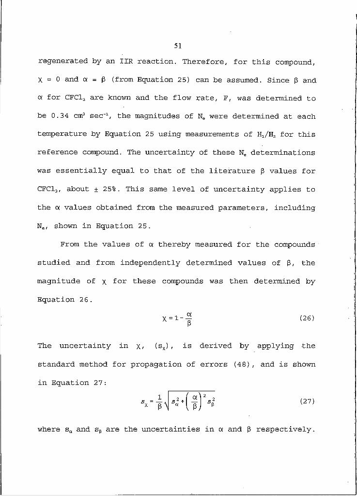
regenerated by an IIR reaction. Therefore, for this compound,
X = O and a = (3 (from Equation 25) can be assumed. Since |3 and
a for CFCl3 are known and the flow rate, F, was determined to
be 0.34 cm3 sec'1, the magnitudes of Ne were determined at each
temperature by Equation 25 using measurements of H1ZH2 for this
reference compound. The uncertainty of these Ne determinations
was essentially equal to that of the literature 3 values for
CFCl3, about ± 25%. This same level of uncertainty applies to
the a. values obtained from the measured parameters, including
Ne, shown in Equation 25.
From the values of ot thereby measured for the compounds
studied and from independently determined values of p, the
magnitude of x for these compounds was then determined by
Equation 26.
X = I - - ^ (26)
The uncertainty in x, (sx) , is derived by applying the
standard method for propagation of errors (48), and is shown
in Equation 27:
where sa and S3 are the uncertainties in a. and 3 respectively.

52
Measurement of EC Rate Constants at Atmospheric Pressure
As was demonstrated in the previous section, the EC rate
constant for the compound of interest must be known to
determine the regeneration coefficient, x • The critical
question as to whether or not the literature EC rate constants
for C7F14 that were determined in a buffer gas of 0.5 Torr (17)
are applicable to buffer gas pressures near I atm must be
addressed. In order to answer that question, experiments were
performed using the dual cell ECD shown in Figure 4. The dual
BCD's were used for the GC detection and analysis of samples
containing CFCl3, CCl4, and C7F14, in which two responses were
simultaneously recorded with 10% methane in argon carrier gas
flowing through the BCD's at atmospheric pressure. The average
electron density within each of the BCD's can be controlled by
the choice of pulse frequency applied to their anodes. For
this study, a very low average electron density (about I x IO6
cm'3) was maintained at all times (46) by setting the pulse
frequency to a relatively high value of 5 x 10s H z . As a
result, only small fractions of the EC active compounds are
destroyed by EC and IIR reactions as they pass through the
dual BCD's under these conditions. This was verified by the

53
observation that the responses of the second ECD to the
compounds studied were only slightly less (less than 15%)
reduced relative to those of the first ECD.
Since the fractional destruction of the EC active
compounds introduced to the first cell is small, the
instantaneous response of the first cell will be proportional
to the product of (3 and [M] 0, where (3 is the EC rate constant
for that compound and [M] 0 is the known concentration of that
compound being introduced to the first ECD. Therefore, under
these conditions, the relative molar responses (peak areas /
moles injected) observed for the EC active compounds will be
directly proportional to the relative EC rate constants for
these compounds in the atmospheric pressure buffer gas.
For CFCl3, CCl4, and C7F14, the average relative ECD
responses in the above experiments at a detector temperature
of I20°C were 1.00, 1.18, and 0.34, respectively (normalized
with respect to the case of CFCl3) . The EC rate constants
determined for these three compounds by the flowing afterglow
method in 0.5 Torr helium buffer gas at 120°C are 3.2 x IO'7,
3.8 x IO"7 (16), and 1.1 x 10"7 (17) cm3 sec"1 respectively.
These EC rate constants are in excellent agreement with the
relative ECD responses observed here in a buffer gas of I atm
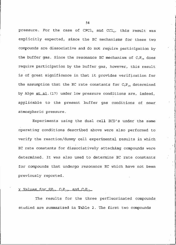
54
pressure. For the case of CFCl3 and CCl4, this result was
explicitly expected, since the EC mechanisms for these two
compounds are dissociative and do not require participation by
the buffer gas. Since the resonance EC mechanism of C7F14 does
require participation by the buffer gas, however, this result
is of great significance in that it provides verification for
the assumption that the EC rate constants for C7F14 determined
by Alge et al.(17) under low pressure conditions are, indeed,
applicable to the present buffer gas conditions of near
atmospheric pressure.
Experiments using the dual cell BCD's under the same
operating conditions described above were also performed to
verify the reaction/dummy cell experimental results in which
EC rate constants for dissociatively attaching compounds were
determined. It was also used to determine EC rate constants
for compounds that undergo resonance EC which have not been
previously reported.
y Values for SF?, C7F14, and C^F12
The results for the three perfluorinated compounds
studied are summarized in Table 2. The first two compounds

55
Table 2.
Summary of results for SF6, • CvF14, and C6F12 with CF2Br2 and CHCl3 as method checks.
Compound Temp(0C)
electrondensity
P(Cm3Sec"1) a
H1Zh 2 0£(Cm3Sec"1) =
Xd
CF3Br2 30 8 .4x10' 3.1x10"? 9.1 3.3x10"? Oe
75 6.4x10' 3.5x10"? 8.7 4.1x10"? 0
120 4 . 0x10s 3.8x10"? 6.4 4.6x10"? 0
180 2.4x10s 4.0x10"? 3.9 4.1x10"? 0
CHCl3 180 3.4x10s 1 .7xl0"8 I . 15 1 .5x10"8 Oe
SF6 30 1.2x10? 3.1x10"? 10.4 2.7x10"? 0 .13±0.31
75 7. 9xl06 3.6x10"? 8.8 3.3x10"? 0.08 + 0.32
120 6.5x10' 4.0x10"? 7.5 3.4x10"? 0 .15±0.30
180 4.0x10' 4.5x10"? 5.4 3.7x10"? 0.17+0.28
C7Fi4 30 1.6x10? 6.8xl0"8 1.60 1 .3xl0"8 0.81+0.07
75 1.1x10? 8.8xl0"8 1.52 1 .6xl0"8 0.8 2 ± 0 .06
120 8.7x10' 1 .1x10"? 1 .50 2 . OxlO"8 0.82 + 0.06
180 5.3x10' 1.3x10"? 1.47 3 . OxlO"8 0.7 7 ± 0 .08
C6F12 30 I .6x10? 1 .6x10"? 3.17 4.6x10" 0.7 1 ± 0 .10
75 9.5x10' 1.7x10"? 2.51 5.4xl0"8 0.6 7 ± 0 .12
120 6.9x10' 1.8x10"? 2.30 6.4x10"8 0.63+0.13
180 3.4x10' 2.1x10"? I . 92 9.4x10"8 0.5 6 ± 0 .IG
a |3 is the electron capture rate constant obtained fromreferences 16 and 49 as determined by the FALP method in 0.5 Torr buffer gas, except for C6F12 which was determined by the present work with the dual cell BCD's at I atm pressure.
b H1ZH2 is the ratio of peak heights, defined in Figure 4.
c a is the experimentally determined quantity defined in Equation 3.

56
Table 2. (continued)
d X is the fraction of IIR events that lead to the regeneration of the parent molecule.
e For these dissociative EC processes, x = 0 is assumed.
shown, CF2Br2 and CHCl3, provide a confirmation of the method
because they are known to attach thermal electrons by the
dissociative EC process. Therefore, x for these compounds can
be assumed to be equal to zero and the magnitude of a observed
should be equal to the known (16) , (49) EC rate constants, |3
(Equation 25) . It is seen that (X is, indeed, essentially equal
to |3 for CF2Br2 and CHCl3, thereby supporting the,validity of
the method. It is noted that the EC rate constant for CHCl3 is
much lower than that of CF2Br2 and, therefore, the ratio of
peak heights, H1ZH2, is only slightly greater than unity for
this compound at 180°C. At lower temperatures, the EC rate
constants of CHCl3 are known to be even smaller and therefore,
the H1ZH2 values observed at lower temperatures were too close
to unity to allow accurate determinations of cx by Equation 3 .
For SF6, the observed values of a in Table 2 are almost
equal to (slightly smaller than) the known |3 values for SF6 at
all temperatures studied. This leads to molecular regeneration

57
coefficients, x, of less than 0.20 at all temperatures. This
result indicates that SF6" is primarily converted to unknown
neutral species upon' recombination with positive ions and that
less than 20% of the SF6" molecular anions are converted back
to SF6. These results are in good agreement with the value of
X = 0.1 ± 0.3 for SFg- previously reported by Valkenburg et al.
(46) using 10% methane in argon buffer gas at 1.0 atm pressure
and 150°C.
For C7F14, the observed values of <x in Table 2 are
distinctly smaller than (about 1/4 as large as) the known
values of (3 for this compound at all temperatures. This leads
to molecular regeneration coefficients, x, that are close to
0.80 at all temperatures studied. This result suggests that
C7F14" is primarily converted back to the molecular species,
C7F14, upon recombination with positive ions and is also in
very good agreement with the previous determination of x =
0.75 ± 0.10 by Valkenburg et a l . at IBO0C .
An alternate explanation of the C7F14 results has been
considered. That is, these results would be explained if the
rate constants for the resonance EC reaction of this compound
under the present conditions of I atm. pressure are much lower
(by a factor of 1/4) at all temperatures than the literature

58
values of (3. As described in the previous section, however,
experiments were performed in order to specifically test this
possibility. In these experiments, it was shown that the
relative EC rate constants for the reference compound, CFCl3,
and C7F14 in an atmospheric pressure buffer gas are in
excellent agreement with the corresponding literature values
of (3 determined in 0.5 Torr helium buffer gas. Furthermore,
it is difficult to envision how the rate constant of a thermal
energy resonance EC reaction could be decreased, rather than
increased, by an increase in pressure. For these reasons, this
alternate explanation of the C7F14 results is not favored.
The x values for SF6 and C7F14 do not exhibit a
significant temperature dependence. However, upon examination
of the x values of C6F12 in Table 2, there is a clear decrease
in x as the temperature is increased from 30° to 180°C. At the
lowest temperature of 30°C, a large amount of the parent
molecule is regenerated upon HR, while at 180°C,
approximately 20% less of the parent molecule is regenerated.
In order to more precisely consider the significance of
the x values listed in Table 2 for SF6, C7F14, and C6F12, it is
informative to also consider the electron capture mass spectra
of these compounds that were measured under the present

Ion
Intensity
59
Figure 10. API mass spectrum of SF6 at 120°C innitrogen buffer gas.

Ion
Intensity
60
200
M/Z
M-
(M-F)"
300
Figure 11. API mass spectrum of C7F14 at 120°C in nitrogenbuffer gas.

61
conditions by atmospheric , pressure ionization mass
spectrometry (APIMS) . First, SF6 and CvF14 will be discussed.
As expected, electron capture by SF6 and C7F14 at
atmospheric pressure occurs primarily by the resonance EC
process leading to molecular anions, M". However, for both of
these compounds, minor fragment ions of the type (M-F)" are
observed in about 0.10 relative abundance at all temperatures
between 3 0° and 180°C. Figures 10 and 11 show the API mass
spectra for SF6 and C7F14 at 120°C in nitrogen buffer gas,
respectively. While a portion of these (M-F)~ ions are known
to be produced along with the M" species in a branched EC
reaction (50), most of the (M-F)" ions are formed in an
atmospheric pressure buffer gas by the reaction of the M~
species with trace water vapor (51) . In view of these side
reactions, the largest possible molecular regeneration
coefficient, x, that might have been expected for either SF6
or C7F14 is about 0.90, rather than 1.00, even if reaction 2
proceeds entirely by pathway 2a. Therefore, the observation
that x ~ 0.80 for C7F14 at all temperatures actually suggests
that about 90% of the molecular anions of this compound are
converted back to the parent molecule upon recombination by
pathway 2a. While the x values reported for SF6 in Table 2

62
will be similarly increased by about 10% by correction for
this effect, this correction is of little significance for the
case of SF6, where destruction is clearly dominated by the IIR
reaction (for example, x = 0.13 at 3O0C is increased only to about x = 0.14 by this correction).
Figures 12 through 15 show the API mass spectra of C6F12
at 30°, 75°, 120°, and 180°C in nitrogen buffer gas. Like SF6
and C7F14, the EC reaction proceeds primarily by the resonance
process. However, the fragment ion (M-F)' is in greater
relative abundance for C6F12 than for SF6 and C7F14, and its
abundance varies with temperature. The absolute intensities of
the (M-F)' ions are 0.28, 0.31, 0.33, and 0.40 at .30°, 75°,
120°, and 180°C respectively. Although a portion of the (M-F)"
ions of C6F12 are undoubtly formed by the reaction of M" with
trace water vapor, the temperature dependence of the formation
of the (M-F)" ion is most likely explained by a branched EC
reaction of the type shown in Reaction 28.
M- (28a)
"Ni(M-F) ■M + e * (M')
(28b)

Ion
Intensity
63
(M-F) '
M/Z
Figure 12. API mass spectrum of C6F12 at 30°C innitrogen buffer gas.

Ion
Intensity
64
(M-F) -
M/Z
Figure 13. API mass spectrum of C6F12 at 75°C innitrogen buffer gas.

Ion
Intensity
65
M-
(M-F) -
150 300
M/Z
Figure 14. API mass spectrum of C6F12 at 120°C innitrogen buffer gas.
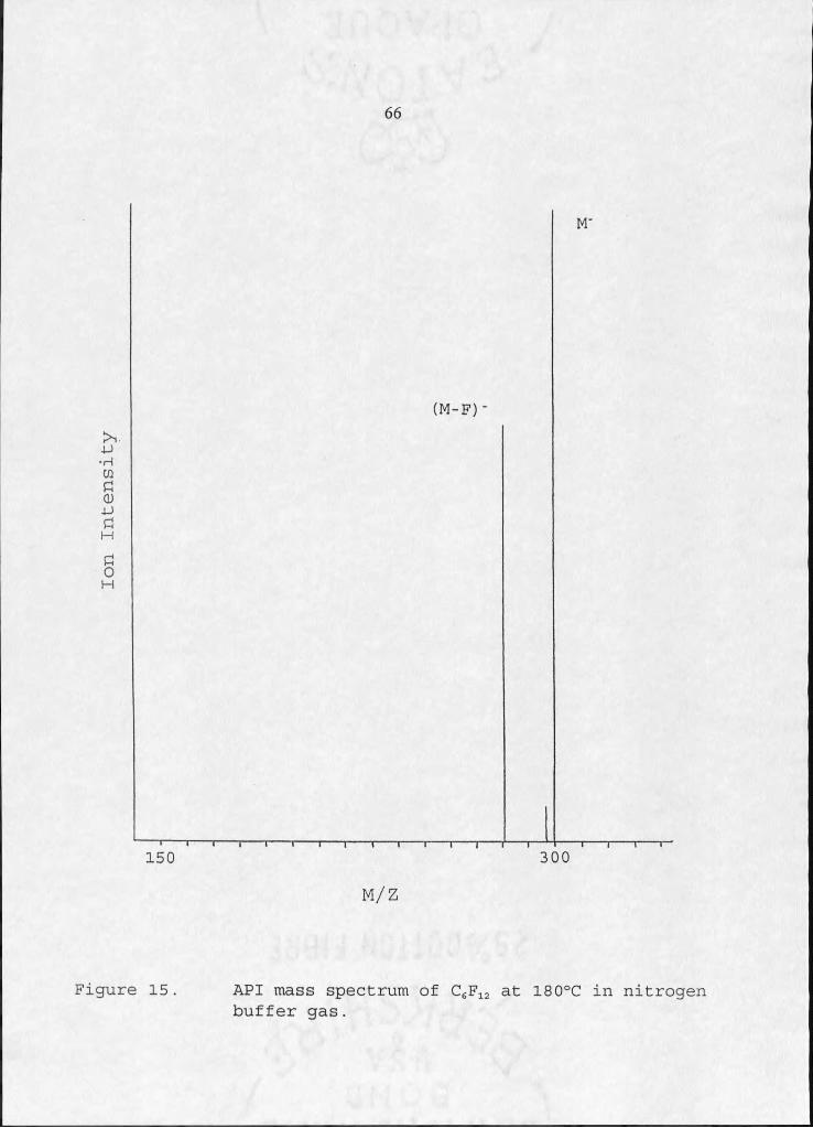
Ion
Intensity
66
(M-F) -
M/Z
Figure 15. API mass spectrum of C6F12 at 180°C in nitrogenbuffer gas.

67
The excited intermediate, (M') *, initially formed upon EC, is
quenched by collisions with buffer gas molecules to form M"
(reaction 28a) . Alternatively, (IYC) * may decay to form (M-F)"
(reaction 28b). The rate constant for the decay reaction, 28b,
has been shown to increase with increasing temperature for
other perfluoro compounds (50). Therefore, it is reasonable to
predict that C6F12 might behave in a similar manner and that
the intensity of the (M-F)" would increase due to the
increased rate of reaction 28b relative to that of reaction
28a with increasing temperature.
Considering the API mass spectra for C6F12, the maximum x
value for this compound are 0.72, 0.69, 0.67, and 0.60 at 30°,
75°, 120°, and I80°C respectively. The experimentally
determined x values of 0.71, 0.67, 0.63, and 0.56 listed in
Table 2 for C6F12 at the above temperatures demonstrate that at
least 93% of the parent molecule is regenerated upon H R.
Effect of Positive Ions on IIR Fate of SFr and C^F11".
The positive ions in the API background mass spectrum shown in
Figure 8 are thought to be the same ions normally present in
the reactor cell, along with an assortment of ions originating
from unavoidable "column bleed" molecules introduced from

68
column #1 in Figure 2. Fbr SF6 and C7F14, experiments were
performed in which this uncontrolled set of positive ions was
converted to a more controlled set by the addition of
trimethylamine (TMA) to the carrier gas. TMA undergoes
reactions similar to those of triethlyamine shown in reactions
21a-c to produce (TMA+H)+ and (TMA-H)+ and also the proton
clusters H+ (TMA) (44) . Table 3 shows the results of these
experiments. When compared to the results in Table 2, the
addition of TMA to the carrier gas has essentially no effects
on the cx and x values observed for these two compounds.
Table 3.
Values of a and x at 180°C with the addition of trimethylamine to the carrier gas*.
Compound <x (cm3 sec"1) XSFe 3.7 x IO"7 0.17
C7F14 3.4 x IO"8 0.74
a Electron densities, listed in Table 2.
(B, and uncertainties are the same as
Two potential effects of adding TMA, to the carrier gas
have been considered. First, is that all possibility of
positive ion-molecule reactions where the neutral is SF6 or
C7F14 would be shut off by the formation of the very stable TMA

69
derived positive ions. Since no effects of TMA were observed,
it is concluded that positive ion-molecule reactions are not
of importance in the reaction cell. This result is not
surprising since the rate constants for even fast ion-molecule
reactions are much slower than the EC rate constants for SFs
and C7F14. Furthermore, Morris et a l . (15) have recently shown
that even more energetic ions, such as NO+ and H+(H2O) are
unreactive towards small perfluoro compounds.
The addition of TMA to the carrier gas is expected toI
have a large effect on the overall exothermicity of the IIR
reactions. For example, by addition of TMA, some of the
positive ions would be converted from H+(H2O) to H+(TMA) . By
this change, the exothermicity of all IIR reactions involving
these two ions would be very significantly reduced, by about
60 kcal mol'1 assuming the proton affinities of H2O and TMA are
165 and 225 kcal mol'1 respectively (52) . One of the least
exothermic reactions envisioned to occur would be that of the
H+(TMA)2 ion with the C7F14" ion, for which the most likely
products can now be stated to be the C7F14 molecule, the H
atom, and two TMA molecules. The heat of this reaction is
still expected to be exothermic by 43 kcal mol'1, assuming an
H atom ionization energy of 313 kcal mol"1 (53), an electron
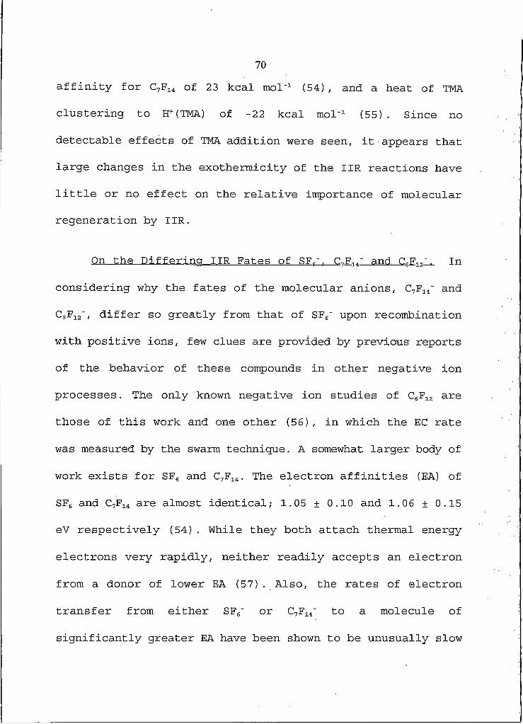
70
affinity for C7F14 of 23 kcal mol"1 (54) , and a heat of TMA
clustering to H+(TMA) of -22 kcal mol"1 (55) . Since no
detectable effects of TMA addition were seen, it appears that
large changes in the exothermicity of the IIR reactions have
little or no effect on the relative importance of molecular
regeneration by IIR.
On the Differing IIR Fates of SFr"._C7F11" and CcF12". In
considering why the fates of the molecular anions, C7F14" and
C6F12", differ so greatly from that of SF6" upon recombination
with positive ions, few clues are provided by previous reports
of the behavior of these compounds in other negative ion
processes. The only known negative ion studies of C6F12 are
those of this work and one other (56), in which the EC rate
was measured by the swarm technique. A somewhat larger body of
work exists for SF6 and C7F14. The electron affinities (EA) of
SF6 and C7F14 are almost identical; 1.05 ± 0.10 and 1.06 ± 0.15
eV respectively (54). While they both attach thermal energy
electrons very rapidly, neither readily accepts an electron
from a donor of lower EA (57) . Also, the rates of electron
transfer from either SF6" or C7F14" to a molecule of
significantly greater EA have been shown to be unusually slow

71
(54). The thresholds for electron photodetachment by SF6" and
C7F14" are both unusually high, about 2.2 eV above their EAs
(18) . These large differences between the EAs and
photodetachment thresholds suggest that large structural
differences exist between the neutral and negatively ionized
forms of both compounds. Another similarity between SF6" and
C7F14" is that both of these anions have been shown to
decompose readily in the presence of protic molecules, such as
methanol or water (51). In view of these numerous
similarities, one might have expected similar behaviors in the
ITR reactions of SF6' and C7F14'.
In an attempt to identify the reason for the very
different behaviors of SF6" and C7F14" upon recombination with
positive ions, the following areas of speculation have been
envisioned. First, if one assumes that the mechanism of the
IIR reactions involves the simple transfer of an electron
between the approaching counter ions, perhaps the SF6 neutral
species finds itself in a distorted configuration following
the electron transfer event from which the stable SF6 geometry
cannot be reattained prior to its dissociation. Support for
this suggestion is found in the photodetachment spectra of SF6"
discussed above (18) and in the fact that the entropy

72
associated with the negative ionization of SF6 has been
reported to be unusually large (58). With this interpretation,
however, one would also have to envision that the
corresponding C7F14 neutral species does manage to achieve its
stable configuration after electron transfer, in spite of
similar photodetachment evidence (18) for large geometric
differences between its neutral and negatively ionized forms.
Additional points of speculation come to mind if recombination
events can also occur by the transfer of ions, such as F",
rather than just by an electron, between more closely-
interacting counterions. If so, perhaps SF6" recombines in this
manner, while C7F14" does not. Alternatively, if the
counterions physically combine to form a reaction complex, as
is commonly thought to occur in ion-molecule reactions,
differing behaviors of SF6" and C7F14' within these reaction
complexes might occur. Because so little is known concerning
the detailed mechanisms of IIR reactions, it is presently
difficult to assess the relative merits of these
possibilities.

73
Implications for the Atmospheric Chemistry of SF,. C1--F11. and
.CsFi2-.- If it is momentarily assumed that the present results
directly apply to the physical conditions existing in the
earth's mesosphere, the following predictions can be made.
Atmospheric SF6 will be destroyed in the mesosphere by its
sequential EC/IIR reactions, while C7F14 and C6F12 will not be
destroyed by their EC/IIR reactions. However, since the
,pressure in the mesosphere is at least three orders of
magnitude lower than the pressure used in this work, the
following expected effects should also be considered. The
basic mechanism of IIR reactions at pressures existing in the
mesosphere is bimolecular, while the mechanism is termolecular
in the atmospheric pressure range due to energy absorbing
collisions of buffer gas molecules with at least one of the
interacting counterions. Therefore, in the high pressure
experiments of this work, a portion of the exothermicity of
the IIR reactions is imparted to the buffer gas molecules,
rather than to the ions alone, as in the bimolecular mechanism
of the mesosphere. In addition, a large portion of the
positive ions existing in the mesosphere, such as 02+ and NO+
(59) , will be of higher energy than those utilized for the
present study. This change would impart greater energies to

74
the counterions at the instant of recombination. Both of the
factors just mentioned might cause greater destruction of the
counterions at low pressures, in spite of the evidence
provided from the present work that the fates of the negative
ions were not noticeably affected by large changes in the
reaction exothermicity. In that case, the destruction of SF6
in the mesosphere by EC/IIR reactions would still be assured,
while the degree of C7F14 and C6F12 destruction by their EC/IIR
reactions in the mesosphere might be greater than predicted on
the basis of the present measurements.
Y Values for Nitronbenzene and Several Substituted Nitrobenzenes
The regeneration coefficient results for the nitrobenzenes
studied are summarized in Table 4. These particular nitro-
Table 4.
Summary of results for nitrobenzenes at 120°C.
Compound electrondensity3
P(cm3 s e c 1) b
H 1ZH2 a.
(cm3 s e c 1)X
NB 8.2x10? 2.6xl0"8 1.35 1.2x10"» 0.9 5 ± 0 .01
O-NO2NB 6 .BxlO7 1 .3xl0"7 16.1 5.3x10"» 0.5 9 ± 0 .12
m -NO2NB 7 . OxlO7 2.2x10"» 1.66 2 .4x10"» 0.89+0.03
P-NO2NB 7 . OxlO7 1 .4xl0"7 25.0 8.9x10"» ' 0.37+0.18
p -PNB 3 . 7xl07 3.5x10"» 1.41 5.7x10"» 0.84 + 0.05

75
a Electron density was determined using CHCl3 as the reference compound.
b (3 was obtained from reference 46 as determined by the PHPMS method at 125°C in 10 Torr methane buffer gas.
Table 4. (continued)
benzenes were chosen because their resonance EC rate constants
have been previously determined (60) , and due to their
compatibility with the chromatography set-up associated with
the reaction/dummy cell apparatus.
The x values range from a high of 0.95 for nitrobenzene, NB, to a low of 0.37 for para dinitrobenzene, p -NO2N B . These
results are interesting in that no obvious trend is apparent
in the amount of compound regenerated upon H R . For example,
the electron affinities of O-NO2NB and m-NO2NB are both 1.65
eV (61), implying equal exothermicities for their IIR
reactions, however, their x values differ substantially. On
the other hand, the EAs of NB and p-FNB (para
fluoronitrobenzene) are close (1.01 and 1.12 eV respectively
(61)) and both exhibit similarly large x value. The compound
with the largest BA, P-NO2NB, exhibits the least amount of
regeneration upon recombination. Many of the nitrobenzenes are
reported to have negative entropies of negative ionization,

76
ASa° (61) . Two of the' compounds studied here, NB and p -NO2NB7
have reported ASa° values of -1,0 and -4.5 cal/K respectively
(61) . When these values are compared with that of SF6 (ASa° =
+18 cal/K), it is clear that large structural differences in
the molecular anions, resulting from EC, do not necessarily
have an effect on the subsequent IIR reactions. As in the case
of the perfluoro compounds discussed in the previous sections,
it is difficult to completely assess the results obtained for
the IIR reactions of these nitrobenzenes.
EC Rate Constants for Dissociatively
Attaching Compounds
The reaction/dummy cell apparatus was used to determine
EC rate constants for compounds that attach electrons by the
dissociative mechanism. For these compounds, x is assumed to
equal zero, thereby allowing the experimentally determined
value, a, to be a direct measure of the EC rate constant for
the compound of interest (Equation 25). The results of these
studies are summarized in Table 5.

77
EC rate constants for dissociatively attaching compounds as determined by the reaction/dummy cell apparatus.
Table 5.
Compound Temp(0C)
Electrondensity
H1ZH2 Oi(Cm3Sec"1) a
P(Cm3S e c 1) b
1,2 dibromo- tetraflouroethane 30 8 .4x10s 7.6 2.7x10"? 1 .6x10"? 9 (25°C)
75 G .4x105 5.6 2.4x10"?
120 4 . OxlO6 5.0 3.4x10-? 2.4x10"? (107°C)
180 2.4x10⁵ 3.4 3.4x10"? 3.0x10"? (2 02°C)
1,2 d ibromo-1,I difluoroethane 30 8 .4xl06 6.5 2.2x10"?
75 6.4x10⁶ 5.0 2.1x10"?
120 4 . OxlO6 4.7 3.1x10"? 2.0x10"? °
180 2.4x10⁶ 3.1 3.0x10"?
CHFBr2 30 8.4x10⁶ 4.0 1.2x10"?
75 6.4x10⁵ 3.3 1.2x10"?
120 4 . OxlO6 2.6 1.4x10"? 1 .5x10"? °
180 2 .4x106 2.4 1 .9x10"?
I ,2 d i b r o m o - 1 ,I ,2 trifluoroethane 30 8 .4xl06 6.3 2.1x10"?
75 6.4x10⁵ 5.0 2.1x10"?
120 4 . OxlO6 4.1 2.6x10"? 2.2x10"? °
180 2.4xl06 2.9 2.6x10"?
CCl3Br 30 1.2x10? 5.6 1.3x10"? 8 .2xl0-6 d
75 7.9xl06 7.8 2.9x10"?
120 6.5x10⁶ 7.6 3.5x10"? 1 .1x10"? =
180 4 . OxlO6 6.1 4.3x10"?

78
Compound Temp(0C)
Electrondensity
H 1ZH2 CL
(Cm3Sec"1) aP
(Cm3Sec"1) b
CH2Br 2 30 8 .4x106 3. 1 8.4x10'8 9.4xl0"8 e
75 6.4x10' 2.6 8.6x10"8 1 .2xl0"7
120 4 . OxlO6 2.6 . 1 .3x10"7 1 .4xl0"7
180 2 .4x106 2.1 1 .6xl0"7 1 .6xl0"7
CH3I 30 8.4xl06 4.6 1 .4xl0"7
75 7 .2x10s 3.9 1 .4xl0"7
120 5.6x10⁶ 3.4 1 .4xl0"7 1.4xl0"7c
180 3 .2x10s 2.7 1 .8x10"7 I . SxlO"7 =
CCl4 30 I .OxlO7 22.7 7.4xl0"7 3 . 9xl0"7f
75 7.3x10s 18.5 8.2x10"7 3 . SxlO"7
120 5.8x10s 13.7 7.4x10"7 3 . 8xl0'7
180 3 .2x10s 7.4 6.8x10"7 3 . 7xl0"7
1/2 dibromo- h exafluoropropane 30 8 .4x10s 20.8 8 . OxlO"7
75 7.2x10s 14.5 6.4x10"7
120 5.6x10s 10.6 5.9xl0“7 4 . 2xl0"7 =
180 3.2x10s 5.8 5 . OxlO"7
CHBr3 30 8.5x10s 4.6 1 .4xl0-7
75 5.1x10s 2.6 I . IxlO"7
120 5. 0x10s 2.3 8 . SxlO"8 I . 3xl0"7 =
180 3 .4x10s I . 6 6 . IxlO"8
I, 1,2,2tetrachloroethane 30 I .6xl07 4.5 7 .4xl0"8
I S 5.IxlO6 1.46 3 . IxlO"8
120 5. 0x10s 1.29 2 . OxlO"8 5 . IxlO"8 c
180 3.4x10s 1.33 3.3xl,0"8
a o: is the experimentally determined EC rate constant. The uncertainty is about 25%.

79
b (3 is the EC rate constant from the literature (0.5 Torr helium buffer gas) , or from dual cell BCD experiments of this work.
c As determined by the dual cell ECD method from this work.
d From reference (62)
e From reference (17)
£ From reference (16)
9 From reference (49)
Table 5. (continued)
The experimentally determined EC rate constants listed in
Table 5 are in rather good agreement with previous results
from the FALP method (16,17,49,62) or the dual cell ECD method
used in the present work. Two major exceptions are noted
however. The EC rate constants determined for CCl4 and 1,2
dibromohexafluoropropane, C3Br2F6, are substantially greater
than the results obtained from different methods (FALP for
CCl4 (17) and dual BCD for C3Br2F6) , and also exceed the
theoretical maximum value (63) for an EC reaction of about
5. OxlO"7 cm3 sec"1 by as much as 64%. These results infer that
a greater amount of the compound is being destroyed in the
reaction cell than what would have been expected from the EC
reaction alone. Three possible explanations for the excess

80
loss of these two compounds within the reaction cell can be
envisioned. The first is an ion-molecule reaction where the
neutral is CCl4 or C3Br2F6. However, the ion-molecule reaction
is not expected to compete with the much faster EC reaction.
In order to positively rule out this possibility, TMA was
added to the carrier gas to.create a very stable, unreactive
set of positive ions, and the experiment with CCl4 was then
repeated at 180°C. As expected, addition of TMA to the carrier
gas had essentially no effect oh the determined EC rate
constant (an increase of only 3% was observed relative to the
case in which no TMA was present) . Therefore, ion-molecule
reactions can be ruled out as the cause of the excess
destruction of CCl4 and C3Br2F6 occurring within the reaction
cell.
The second possible explanation for the excess
destruction of CCl4 and C3Br2F6 is the . reaction of these
compounds with gas phase radicals that originate from trace
buffer gas impurities. However, the rate constants for the
fastest radical-neutral reactions have rate constants that are
on the order of I x IO"10 cm3 s e c 1 (26) , approximately three
orders of magnitude less than the EC reactions of CCl4 and
C3Br2F6. Therefore, unless the density of gas phase radicals is

81
more than three orders of magnitude greater than that of
electrons, it is not anticipated that radial-neutral reactions
can compete effectively with EC for the destruction of these
compounds.
The final explanation envisioned for the excess loss of
these compounds is a surface-assisted destruction mechanism
occurring on the walls of the reaction cell. Previous reports
by Sears et a l . (26) and Culbertson et a l . (64) have
demonstrated that surface assisted reactions can be very
efficient and the products of these reactions can dominate the
high pressure electron capture (HPEC) mass spectrum obtained
at 0.1 Torr buffer gas pressure. In those studies, it was
shown that neutral analyte molecules could diffuse to the
walls of the ion source where they were altered by reactions
with radical species, such as H- and CH3-, that were present on
the surface. One significant difference between these studies
and the present work, however, is the buffer gas pressure.
Diffusion- of neutral molecules at 1010 Torr (present
conditions) will be much slower than the HPEC conditions (0.1
Torr). It is therefore necessary to calculate the first order
rate constant for diffusion at 1010 Torr and compare it with
the main competitive process, EC, to determine if a surface

82
assisted destruction mechanism is feasible.
The first order rate constant for diffusion is again
given by DnA"2, where Dn is the diffusion coefficient of the
neutral and A is the characteristic diffusion length of the
reaction cell (25) . The magnitude of Dn can be calculated
using Equation 29,
\K2 + y 22SnnS 2̂ (29)
where V 1 and v2 are the most probable velocities of the neutral
of interest and the buffer gas, n is the buffer gas density,
and S12 is the average molecular diameter of the neutral and
buffer gas molecule. Using S12 equals 6 x IO'8 cm for all
neutrals (26) and v equals 5.2 x IO4 cm s e c 1 and 2.2 x IO4 cm
sec'1 for N2 and CCl4 respectively, Dn for CCl4 is then 0.12 cm2
sec1. A value of A may be obtained by dividing the radius of
the reaction cell (0.4 cm) by n. Therefore, A = 0.13 cm and the
first order rate constant of diffusion for CCl4 at 180°C is
then 7.1 s e c 1. Comparing this to the pseudo first order EC
rate constant for CCl4 of 1.8 s e c 1, (obtained from kobs =
kEC[e] , where kec = 3.7 x 10"7 cm3 s e c 1 (16) and [e] = 4.8 x IO6
cm'3) , it is reasonable to predict that the surface-assisted
destruction of CCl4 and C3Br2F6 could be operative under the

83present conditions of 1010 Torr based on the fact that the
rate constant for diffusion is about four times greater than
that of electron capture. Upon contact with the surface of the
reaction cell wall, CCl4 and C3Br2F6 could be altered by-
reactions with radical species or some other surface
contaminant. This would then account for the excess loss of
these Compounds with the reaction cell.
The reaction/dummy cell apparatus has proven to be an
effective way of determining EC rate constants for
dissociatively attaching compounds. For compounds whose
determined EC rate constants are suspected of being too large,
the dual cell ECD experiment provides an excellent check of
the reaction/dummy cell method, since no evidence of the side
reactions or inflated EC rate constants discussed above has
been observed with the dual ECDs.

84
SUMMARY
Gas phase ion-ion recombination can provide the dominant
loss mechanism for ions within partially ionized gases under
many commonly encountered physical conditions. For this
reason, many studies have investigated the rates of IIR
reactions, and many theories have been devised to explain the
mechanism by which IIR occurs. However, very little is known
about the neutral products formed from IIR reactions, in spite
of the importance that these products can have on atmospheric'
chemistry and to the response of certain analytical detectors.
The results from one previous study that investigated the
products of IIR using a dual cell ECD were based on two
critical assumptions that could not be proven experimentally.
Therefore, the focus of this work has been to build an
apparatus to definitively study the products of IIR reactions
at atmospheric pressure. More specifically, this apparatus was
used to determine the extent to which molecular anions were
regenerated to their parent neutral upon recombination with
positive ions. This apparatus was also used to determine EC
rate constants for dissociatively electron attaching

85
compounds. In addition, experiments using an atmospheric
pressure ionization mass spectrometer were performed to
determine what effect the nature of the recombining ions had
on the rate of H R .
When two polyatomic ions of opposite charge undergo
recombination, the neutral products can be fragments of the
recombining ions, or if a simple electron transfer mechanism
is operative, the parent molecules can be regenerated. If an
electron attaching compound undergoes resonance electron
capture to form its molecular anion and the parent neutral is
regenerated upon H R , it may then undergo a second EC/IIR
reaction. This process could occur many times while the
compound is within the ECD. Hence, the ECD response to this
compound would be enhanced relative to the case in which the
parent molecule is not regenerated upon IIR. The regeneration
mechanism could also have a very important effect on the
atmospheric chemistry of perfluoro compounds. Many perfluoro
compounds, such as SF6, attach electrons very rapidly and are
also extremely immune to the oxidative and photochemical
processes that destroy most compounds in the troposphere or
stratosphere. Therefore, such compounds can enter the
mesosphere where reactions with free electrons may occur. If

86the compound is then regenerated upon the subsequent IIR
reaction, it could significantly increase its atmospheric
lifetime, which is important because most PFCs are efficient
greenhouse gases.
Three PFCs, SF6, C7F14, and C6F12, all of which undergo
resonance EC, were studied using the reaction/dummy cell
apparatus to determine the extent to which the molecular anion
was regenerated upon HR. By comparing the ECD response to the
compound of interest surviving passage through the reaction
cell (where EC and IIR occur) , to that of the dummy cell,
(where no reactions take place), in conjunction with the
conservation equations that describe the cell, conclusions
were drawn about the amount of compound being regenerated upon
HR. The results showed that the molecular anions of C7F14 and
C6F12 are almost completely regenerated to their parent neutral
upon H R , while recombination of the molecular anion of SF6
with positive ions tends to form other unknown neutral
species. In order to draw these conclusions based on the
experimental data obtained from the reaction/dummy cell
apparatus, it was also necessary to know the EC rate constant
for these compounds at atmospheric pressure. This was achieved
by using a dual cell ECD in the following manner. A gaseous

87
sample containing the compound ■ of interest and the
dissociatively electron attaching reference compound, CFCl3,
were chromatographicalIy introduced to the dual cell BCD.
Instrumental parameters could be varied on the dual cell BCD
such that regeneration of the compound of interest upon IIR
could be reduced to a negligible level. Under these
conditions, the molar BCD response of these compounds will
reflect their relative EC rate constants. Because the EC rate
constant of CFCl3 is well known, the relative EC rate constant
for the compound of interest could be determined.
For compounds that capture electrons by the dissociative
mechanism, the reaction/dummy cell apparatus was found to be
very useful for the determination of EC rate constants. Since
regeneration of the parent molecule from IIR is not possible
for these compounds, the experimentally determined quantity
was directly equal to the EC rate constant. The results
obtained by this method were in good agreement with previous
measurements, when available. For those compounds whose EC
rate constants had not been previously measured, the dual cell
ECD was used in the manner described above as a second
determination of the EC rate constant. The results between the
these two methods were also in good agreement. Two exceptions

88
to the good, agreement between methods were noted. For CCl4 and
1/2 dibromohexafluoropropane (C3Br2F6) , the EC rate constants
determined by the reaction/dummy cell method were
substantially greater than those of the other methods, and
also exceeded the maximum value predicted by theory by as much
as 64%. Some process was destroying more of these compounds in
the reaction cell than what was expected. A possible
explanation for the excess loss of these compounds in the
reaction cell is thought to be a surface assisted destruction
mechanism. It is considered feasible for the neutral CCl4 or
C3Br2F6 molecule to diffuse to the surface of the reaction cell
where it could react with radical species or other impurities
present on the surface to form an altered compound, thereby
accounting for the additional destruction of these compounds.
To determine what effect the nature of the recombining
ions has on the rate of HR, an experiment was devised using
the APIMS as follows. First, a stable set of positive ions was
created in the APIMS ion .source by the addition of
triethylamine to the buffer gas. Second, strongly electron
attaching compounds were introduced to the ion source to
saturate the negative charge side of the plasma. Compounds
were chosen such that Cl", Br", I", SF6", and C7F14" were

89
produced upon EC. The total positive ion signal was then
monitored while the electron attaching compounds were
introduced. The intensity of the total positive ion signal is
proportional to (l/R)1/2, where R is the recombination rate
constant. Thus, by comparing the change in the positive ion
signal when the EC active compound enters the ion source, the
relative IIR rate constants could be determined. The first
observation of this experiment was that the positive ion
signal increased when the EC active compounds were introduced.
This infers that positive ion-electron recombination is faster
than ion-ion recombination. This result was expected based on
literature values for the rate constants for these two
reactions. The second observation was that the positive ion
signal increased by the same amount, irrespective of the
nature of the negative ion. This indicates that the nature of
the ions used for this study had no effect on the IIR rate
constant. The rate constant for H R, based on the percent
increase of the positive ion signal, was calculated to be 2.0
x 10"s cm3 sec-1, which is in excellent agreement with the
literature values.

LITERATURE CITED

91
1. Bowers, M . T.; Gas Phase Ion Chemistry. Vol I . Acedemic Press: New York, 1979.
2. Bowers, M. T.; Gas Phase Ion Chemistry. Vol IIr Acedemic Press: New York, 1979.
3. Bowers, M. T.; Gas Phase Ion Chemistry. Vol III. Acedemic Press: New York, 1984.
4. Watson, J . T.; Introduction to Mass Spectrometry, Raven Press: New York, 1985.
5. Harrison, A. G . Chemical Ionization Mass Spectrometry, Second Edition, CRC Press: Boca Raton, 1992?
6. Zlatkis, A.; Poole, C . F.; Electron Capture. Theory and Practice in Chromatography, Elsevier: New York, 1981.
7. Carroll, D . I.; Dzidic, I.; Horning, E . C.; Stillwell, R . N . Appl Spectros Rev. 1981, 17, 337.
8. Eiceman, G . A.; Karpas,. Z.; Ion Mobility Spectrometry. CRC press: Boca Raton, 1994.
9. Fenn, J. B.; Mann, M.; Meng, C . K.; Wong, S . F.;Whitehouse, C.; Science. 1989, 246, 64.
10. Adams, N. G.; Smith, D.; in Techniques for the Study of Ion Molecule Reactions, John Wiley and Sons: New York, 1988.
11. Kebarle; P.; in Techniques for the Study o£ Ion Molecule Reactions. John Wiley and Sons: New York, 1988.
12. Lovelock, J. E.; Lipsky, S . R.; J Am Chem Soc. 1960, 82, 431.
13. Siegel, M . W.; McGowen, M . C.; J Chromatogr. 1976, 122, 397.
14. Grimsrud, E .P .; Warden, S . W.; Anal Chem. 1980, 52, 1842.

15. Morris, R . A.; Miller, T . M.; Viggiano, A. A.; Paulson,J. F.; Solomon, S . ; Reid, G. ; J Geophys Res. 1995, 100,1287 .
16. Smith, D.; Adams, N. G.; Alge, E.; J Phys B : At Mol Phys.1984, 17, 461.
17. Alge, E.; Adams, N. G.; Smith, D.; J Phys B : At Mol Phys. 1984, 17, 3827.
18. Mock, R. S.; Grimsrud, E . P.; Chem Phys Lett. 1991, 184, 99 .
19. Barrow, G. M.; Physical Chemistry. McGraw Hill: New York,1979, 4th ed.; chapter 2.
20. Meot-Ner, M.; in Gas Phase Ion Chemistry. Vol I r Bowers, M. T. ed., Acedemic Press: New York, 1979; chapter 6.
21. American Institute of Physics Handbook. 3rd ed.; Marion, J. B.; Gray, D . E., eds., McGraw Hill: New York, .1972; chapter 8, p 184.
22. Gobby, P. L.; Grimsrud, E . P.; Warden, S . W.; Anal Chem.1980, 52, 473.
23. Defence Nuclear Agency Reaction Rate Handbook. 4th rev.; Biondi, M . A.; Bortner, M . H.; Baurer, T..; eds.; 1975; chapter 16, pp 16-27.
24. McGowen, S.; Canad J Phys. 1967, 45, 439.
25. Collision Phenomena in Ionized Gasesr McDaniel,. E . W. ; John Wiley & Sons: New York, 1964; chapter 10.
26. Sears, L . J.; Campbell, J. A.; Grimsrud, E . P.; Biomed and Enviro Mass Spectrom. 1987, 14, 401.
27. Thomson, J. J.; Rutherford, E . R.; Phil. Mag. 1896, 42, 392 .
92

93
28. Rutherford, E.; Phil Mag. 1897, 47, 422.
29. Langevin, P.; Ann Chim Phya. 1903, 28, 289, 443.
30. Mahan, B . H.; Advances in Chemical Physiner Vol 23;Prigogine, I.; Rice, S . A.,; eds. ; Wiley: New York, 1973; pp 1- 40 .
31.. Thomson, J. J.; Phil Mag. 1924, 47, 337.
32. Sayers, J.; Proc Roy Soc (London) Ser A . 1938, 169, 83.
33. Gardener, M . E.; Phys Rev. 1938, 53, 75.
34. Machler, W.; Z Physik. 1936, 104, I.
35 . Mahan, B . H. ; Person, J. C. ; J Chem Phvs . 1964, 40, 392.
36. Mahan, B . H. ; Person, J. C. ; J Chem Phvs. 1964, 40, 2851.
37. Natanson, G . L.; Soviet Phys-Tech Phys. 1959, 4 , 1263.
38. Bates, D . R.; Moffett, R . J.; Proc Roy Soc (London) SerA. 1966, 291, I.
39. Bates, D. R.; Flannery, M. R.; Proc Roy Soc (London) SerA. 1986, 302, 367.
40. Knighton, W . B.; Grimsrud, E . P.; Anal Chem. 1982, 54, 1892.
41. Zook, D . R.; Knighton, W. B.; Grimsrud, E . P.; Int J Mass Spectrom Ion Processes. 1991, 63, 104.
42. Grimsrud, E . P.; Anal Chem. 1978, 50, 382.
43. Siegel, M. W.; Fite, W. L.; J Phys Chem. 1976, 80, 2871.
44. Grimsrud, E . P.; J Chromatog. 1984, 312, 47.

94
45. Smith, D.; Adams, N. G.; Church, M. J.; J Phys B . 1978, 11, 4041.
46. Valkenburg, C . A.; Krieger, L . A.; Grimsrud, E . P.; J Chem Phys. 1987, 86, 6782.
47. Grimsrud, E . P.; Connolly, M. J.; J Chromatogr. 1982,239, 397.
48. Peters, D . G.; Hayes, J. M.; Heiftj e, G. M.; Chemical Separations and Measurements r Saunders: Philadelphia, 1974.
49. Smith, D.; Herd, C . R.; Adams, N.G.; Paulson J. F.; Int J Mass Spectrom Ion Processes. 1990, 96, 341.
50. Fehsenfeld-, F . C.; J Chem Phys. 1970, 53, 2000.
51. Knighton, W. B .; Zook, D . R.; Grimsrud, E . P.; J Am Soc Mass Spectrom. 1990, I, 372.
52. Szulejko, J . E.; McMahon, T . B.; J Am Chem Soc. 1993, 115, 7839.
53. Lange's Handbook of Chemistry. Dean, J. A.; McGraw Hill: New York, 1992.
54. Grimsrud, E . P.; Chowdhury, S.; Kebarle, P.; J Chem Phys. 1985, 83, 1059.
55. Yamdangi, R.; Kebarle, P.; J Am Chem Soc. 1973, 95, 3504.
56. Pai, R. Y.; Christophorou, L. G.; Christodoulides, A. A.; J Chem Phys. 1979, 70, 1169.
57. Fehsenfeld, F. C.; J Chem Phys. 1971, 54, 438.
58. Chowdhury, S.; Heinis, T.; Grimsrud, E.P.; Kebarle, P.; ,T Phys Chem. 1986, 90, 2747.

MONTANA STATE UNIVERSITY LIBRARIES