Embed Size (px)
Citation preview
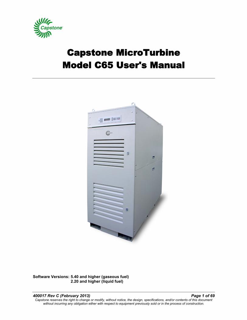
400017 Rev C (February 2013) Page 1 of 69 Capstone reserves the right to change or modify, without notice, the design, specifications, and/or contents of this document
without incurring any obligation either with respect to equipment previously sold or in the process of construction.
Capstone MicroTurbine Model C65 User's Manual
Software Versions: 5.40 and higher (gaseous fuel)
2.20 and higher (liquid fuel)

Capstone Turbine Corporation Model C65 User’s Manual
Page 2 of 69 400017 Rev C (February 2013) Capstone reserves the right to change or modify, without notice, the design, specifications, and/or contents of this document
without incurring any obligation either with respect to equipment previously sold or in the process of construction.
Capstone Turbine Corporation
21211 Nordhoff Street • Chatsworth • CA 91311 • USA Telephone: (818) 407-3600 Facsimile: (818) 734-5382
Website: www.capstoneturbine.com
Capstone Technical Support Telephone: (866) 4-CAPSTONE or (866) 422-7786
E-mail: [email protected] Copyright © 2013 Capstone Turbine Corporation. All Rights Reserved.
Capstone Turbine Corporation Model C65 User’s Manual
400017 Rev C (February 2013) Page 3 of 69 Capstone reserves the right to change or modify, without notice, the design, specifications, and/or contents of this document
without incurring any obligation either with respect to equipment previously sold or in the process of construction.
Table of Contents 1. Introduction .................................................................................................................... 7
1.1. Safety Information ................................................................................................. 7 1.1.1. Symbols ................................................................................................... 8 1.1.2. General Precautions ................................................................................. 8 1.1.3. Electrical Precautions ............................................................................... 9 1.1.4. Fuel Precautions .................................................................................... 10 1.1.5. Exhaust Precautions .............................................................................. 10 1.1.6. Acoustic Emissions Precautions ............................................................. 11
1.2. Certifications, Permits, and Codes .......................................................................11 1.3. Output Measurements ..........................................................................................11
1.3.1. ISO Conditions ....................................................................................... 11 1.3.2. Pressure ................................................................................................. 11 1.3.3. Volume ................................................................................................... 12 1.3.4. Heating Values ....................................................................................... 12 1.3.5. Microturbine Performance ...................................................................... 12 1.3.6. Grid Connect Output .............................................................................. 12 1.3.7. Stand Alone Output ................................................................................ 12 1.3.8. Power Quality ......................................................................................... 12 1.3.9. Heat Output ............................................................................................ 12
1.4. Referenced Documents .......................................................................................13 2. Microturbine Description ................................................................................................14
2.1. User Interface ......................................................................................................18 2.2. Microturbine Features ..........................................................................................19
2.2.1. Microturbine Engine ............................................................................... 19 2.2.2. Air Bearings ............................................................................................ 20 2.2.3. Digital Power Electronics ........................................................................ 20 2.2.4. Fuel System ........................................................................................... 21 2.2.5. Emissions ............................................................................................... 21 2.2.6. Enclosure ............................................................................................... 21 2.2.7. Integrated Combined Heating and Power (ICHP) ................................... 22 2.2.8. Hazardous Location Option .................................................................... 22 2.2.9. Offshore Option ...................................................................................... 22 2.2.10. Capstone Remote Monitoring Software .................................................. 22 2.2.11. Grid Connect Mode ................................................................................ 23 2.2.12. Dual Mode .............................................................................................. 23 2.2.13. MultiPac Power ...................................................................................... 23
3. Microturbine Operation ..................................................................................................24 3.1. Basic Microturbine Operation ...............................................................................24
3.1.1. Communications .................................................................................... 24 3.1.2. Operational Data .................................................................................... 25 3.1.3. Control Device Authority and Priority ...................................................... 25
Capstone Turbine Corporation Model C65 User’s Manual
Page 4 of 69 400017 Rev C (February 2013) Capstone reserves the right to change or modify, without notice, the design, specifications, and/or contents of this document
without incurring any obligation either with respect to equipment previously sold or in the process of construction.
3.1.4. Startup ................................................................................................... 25 3.1.5. Shutdown ............................................................................................... 25 3.1.6. Emergency Stop (E-Stop) ....................................................................... 26 3.1.7. Restart ................................................................................................... 26
3.2. Grid Connect Operation .......................................................................................26 3.2.1. Grid Connect Dispatch ........................................................................... 27 3.2.2. Configuring Grid Connect ....................................................................... 27 3.2.3. Grid Connect Interlock ............................................................................ 27 3.2.4. Grid Connect Mode Enable .................................................................... 27 3.2.5. Starting a Grid Connect System ............................................................. 27 3.2.6. Stopping a Grid Connect System ........................................................... 27 3.2.7. Grid Connect Power Demand ................................................................. 28
3.3. Stand Alone Operation .........................................................................................28 3.3.1. Configuring Stand Alone......................................................................... 28 3.3.2. Stand Alone Interlock ............................................................................. 28 3.3.3. Stand Alone Mode Enable ...................................................................... 28 3.3.4. Stand Alone Battery ............................................................................... 29 3.3.5. Stand Alone Battery Isolation Switch ...................................................... 29 3.3.6. System Sleep in Stand Alone Mode ....................................................... 30 3.3.7. Waking a Stand Alone Microturbine ....................................................... 30 3.3.8. Starting a Stand Alone System ............................................................... 30 3.3.9. Enabling Stand Alone Power Output ...................................................... 30 3.3.10. Stand Alone System Power Level .......................................................... 31 3.3.11. Disabling Stand Alone Power Output...................................................... 31 3.3.12. Stopping a Stand Alone System ............................................................. 31
3.4. Dual Mode Operation ...........................................................................................31 3.4.1. Capstone DMSC .................................................................................... 31 3.4.2. Configuring Dual Mode ........................................................................... 32 3.4.3. Setting the System for Dual Mode Operation .......................................... 32 3.4.4. Switching Times for Dual Mode .............................................................. 32
3.5. MultiPac Operation ..............................................................................................32 3.5.1. MultiPac Grid Connect Operation ........................................................... 33 3.5.2. MultiPac Stand Alone Operation ............................................................. 33 3.5.3. MultiPac Redundancy ............................................................................ 33 3.5.4. MultiPac Enable/Disable......................................................................... 33 3.5.5. Changing the Master Unit in a MultiPac using the Display Panel ............ 34
3.6. ICHP Operation ....................................................................................................35 3.6.1. Thermal Bypass ..................................................................................... 35 3.6.2. Electrical Priority .................................................................................... 35 3.6.3. Thermal Priority ...................................................................................... 36
3.7. Hazardous Location Operation .............................................................................36
Capstone Turbine Corporation Model C65 User’s Manual
400017 Rev C (February 2013) Page 5 of 69 Capstone reserves the right to change or modify, without notice, the design, specifications, and/or contents of this document
without incurring any obligation either with respect to equipment previously sold or in the process of construction.
4. Using the Display Panel ................................................................................................37 4.1. Display Panel Areas .............................................................................................38 4.2. Menu Navigation ..................................................................................................39 4.3. Display Panel Data Entry .....................................................................................39
4.3.1. Logging On with a Password .................................................................. 39 4.4. Display Panel Menus – Overview .........................................................................40 4.5. System Data Menu ..............................................................................................42
4.5.1. Turbine Output Submenu ....................................................................... 42 4.5.2. System Output ....................................................................................... 42 4.5.3. Clear Incident Submenu ......................................................................... 43 4.5.4. Clear Fuel Fault Submenu ...................................................................... 43 4.5.5. Vent Monitor Submenu ........................................................................... 43 4.5.6. System Configuration Submenu ............................................................. 44 4.5.7. System Demand Submenu ..................................................................... 45 4.5.8. System Power Factor ............................................................................. 46 4.5.9. Control Access Submenu ....................................................................... 46 4.5.10. Enter Password Submenu ...................................................................... 47 4.5.11. Logoff Submenu ..................................................................................... 47 4.5.12. Reboot Submenu ................................................................................... 47
4.6. Grid Connect Menu ..............................................................................................48 4.6.1. Stored Demand Submenu ...................................................................... 48 4.6.2. Under Voltage Submenu ........................................................................ 49 4.6.3. Over Voltage Submenu .......................................................................... 50 4.6.4. Fast Under Voltage Submenu ................................................................ 50 4.6.5. Fast Over Voltage Submenu .................................................................. 51 4.6.6. Under Frequency Submenu ................................................................... 51 4.6.7. Over Frequency Submenu ..................................................................... 52 4.6.8. Enable Mode Submenu .......................................................................... 52 4.6.9. Reconnect Delay Submenu .................................................................... 52 4.6.10. Active Power Foldback on Over Frequency ............................................ 53
4.7. Stand Alone Menu ...............................................................................................53 4.7.1. Voltage Submenu ................................................................................... 54 4.7.2. Under Voltage Submenu ........................................................................ 54 4.7.3. Over Voltage Submenu .......................................................................... 55 4.7.4. Frequency Submenu .............................................................................. 55 4.7.5. Under Frequency Submenu ................................................................... 55 4.7.6. Over Frequency Submenu ..................................................................... 56 4.7.7. MultiPac Minimum Power Submenu ....................................................... 56 4.7.8. Fast Transfer Delay Submenu ................................................................ 57 4.7.9. Stand Alone Load Wait Submenu ........................................................... 57 4.7.10. Local Battery Charge Submenu .............................................................. 57
4.8. Unit Data Menu ....................................................................................................58
Capstone Turbine Corporation Model C65 User’s Manual
Page 6 of 69 400017 Rev C (February 2013) Capstone reserves the right to change or modify, without notice, the design, specifications, and/or contents of this document
without incurring any obligation either with respect to equipment previously sold or in the process of construction.
5. Microturbine Preventive Maintenance ...........................................................................59 5.1. Scheduled Maintenance .......................................................................................59 5.2. Preventive Maintenance .......................................................................................59
5.2.1. Microturbine Inlet Air Filter ...................................................................... 59 5.2.2. External Fuel Filter ................................................................................. 60 5.2.3. Battery Maintenance During Storage ...................................................... 60 5.2.4. Battery Charge Management ................................................................. 61 5.2.5. Warranty ................................................................................................ 62
6. Troubleshooting ............................................................................................................62 6.1. Incidents ..............................................................................................................62 6.2. Incident System Severity Levels ..........................................................................62 6.3. Incident Display Format .......................................................................................63 6.4. Incident Records ..................................................................................................63 6.5. Isolation Messages ..............................................................................................64
6.5.1. Internal ................................................................................................... 64 6.5.2. Fuel ........................................................................................................ 64 6.5.3. Grid ........................................................................................................ 64 6.5.4. Lo-Temp/Hi-Temp/Hi-Alt ......................................................................... 64 6.5.5. E-Stop .................................................................................................... 65 6.5.6. User Conn (User Connection) ................................................................ 65
6.6. Basic Troubleshooting Procedures.......................................................................65 6.6.1. Troubleshooting Procedures for Standard C65 Model ............................ 65 6.6.2. Troubleshooting Procedures for C65 Hazardous Location Model ........... 66
7. Product Support ............................................................................................................68
List of Figures Figure 1. C65 Microturbine Configurations ..........................................................................15 Figure 2. C65 Microturbine External Features .....................................................................16 Figure 3. C65 HRM Connections.........................................................................................17 Figure 4. User Port Location (Microturbine Rear View) .......................................................18 Figure 5. Typical Capstone Model C65 Microturbine Engine (Cutaway View) .....................20 Figure 6. Battery Isolation Switch (Lower Front View with Front Door Open) ......................29 Figure 7. Pushbutton Display Panel ....................................................................................37 Figure 8. Touch Key Display Panel .....................................................................................37 Figure 9. Display Panel Menu Function Hierarchy ...............................................................41
List of Tables Table 1. Maximum Recharge Intervals ................................................................................60 Table 2. Maximum Recharge Intervals in Sleep Mode ........................................................61
Capstone Turbine Corporation Model C65 User’s Manual
400017 Rev C (February 2013) Page 7 of 69 Capstone reserves the right to change or modify, without notice, the design, specifications, and/or contents of this document
without incurring any obligation either with respect to equipment previously sold or in the process of construction.
1. Introduction This document provides user instructions to operate and maintain the Capstone Turbine Corporation Model C65 Microturbine. This document is intended for user personnel who may not have specific training on the microturbine (sometimes abbreviated as microturbine in this manual). Capstone Authorized Service Providers (ASPs) have received rigorous training and have been certified to perform commissioning, troubleshooting, and repair of the microturbine.
Revision A and later of this document reflects C65 microturbine with software version 5.XX, which meets the requirements of IEEE 1547.1 and the UL1741 compliance updates effective May 2007. Revision C and later of this document reflects software version 5.40 and higher (gaseous fuel), and 2.20 and higher (liquid fuel), which adds power factor adjustment capability and VDE compliance for grid connect operation.
Basic troubleshooting is included in this manual, but only Capstone Authorized Service Providers are permitted to perform detailed troubleshooting and repair of the equipment. For detailed technical data, or for service to the microturbine, contact your Capstone Authorized Service Provider.
User personnel who have not received certification of satisfactory completion of the Authorized Service Provider training should not attempt any procedures other than those specifically described in this document.
1.1. Safety Information This section presents safety information for the user of Capstone Turbine Corporation microturbines. The user must read and understand this manual before operation of the equipment. Failure to obey all safety precautions and general instructions may cause personal injury and/or damage to the equipment.
The Capstone microturbine is an advanced power generation system with user and material safety foremost in mind. Fail-safe operation includes mechanical systems, electrical systems, and engine control software.
It is the user's responsibility to read and obey all safety procedures and to become familiar with these procedures and how to safely operate this equipment.
Capstone Turbine Corporation Model C65 User’s Manual
Page 8 of 69 400017 Rev C (February 2013) Capstone reserves the right to change or modify, without notice, the design, specifications, and/or contents of this document
without incurring any obligation either with respect to equipment previously sold or in the process of construction.
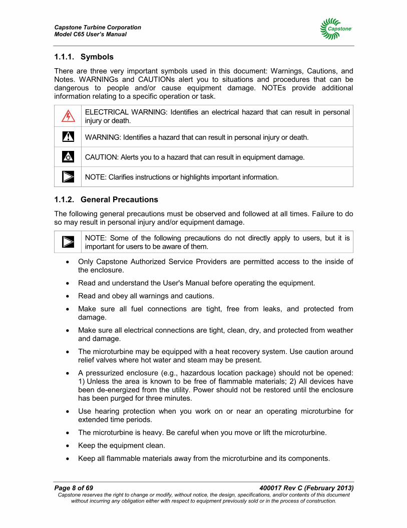
1.1.1. Symbols
There are three very important symbols used in this document: Warnings, Cautions, and Notes. WARNINGs and CAUTIONs alert you to situations and procedures that can be dangerous to people and/or cause equipment damage. NOTEs provide additional information relating to a specific operation or task.
ELECTRICAL WARNING: Identifies an electrical hazard that can result in personal injury or death.
WARNING: Identifies a hazard that can result in personal injury or death.
CAUTION: Alerts you to a hazard that can result in equipment damage.
NOTE: Clarifies instructions or highlights important information.
1.1.2. General Precautions
The following general precautions must be observed and followed at all times. Failure to do so may result in personal injury and/or equipment damage.
NOTE: Some of the following precautions do not directly apply to users, but it is important for users to be aware of them.
• Only Capstone Authorized Service Providers are permitted access to the inside of the enclosure.
• Read and understand the User's Manual before operating the equipment.
• Read and obey all warnings and cautions.
• Make sure all fuel connections are tight, free from leaks, and protected from damage.
• Make sure all electrical connections are tight, clean, dry, and protected from weather and damage.
• The microturbine may be equipped with a heat recovery system. Use caution around relief valves where hot water and steam may be present.
• A pressurized enclosure (e.g., hazardous location package) should not be opened: 1) Unless the area is known to be free of flammable materials; 2) All devices have been de-energized from the utility. Power should not be restored until the enclosure has been purged for three minutes.
• Use hearing protection when you work on or near an operating microturbine for extended time periods.
• The microturbine is heavy. Be careful when you move or lift the microturbine.
• Keep the equipment clean.
• Keep all flammable materials away from the microturbine and its components.
Capstone Turbine Corporation Model C65 User’s Manual
400017 Rev C (February 2013) Page 9 of 69 Capstone reserves the right to change or modify, without notice, the design, specifications, and/or contents of this document
without incurring any obligation either with respect to equipment previously sold or in the process of construction.
• Do not operate or work on the equipment if mentally or physically impaired, or after consumption of alcohol or drugs.
• Make sure all fasteners are installed and properly tightened.
• Keep an ABC rated fire extinguisher near the microturbine.
• Obey all applicable local, state, and national codes and regulations.
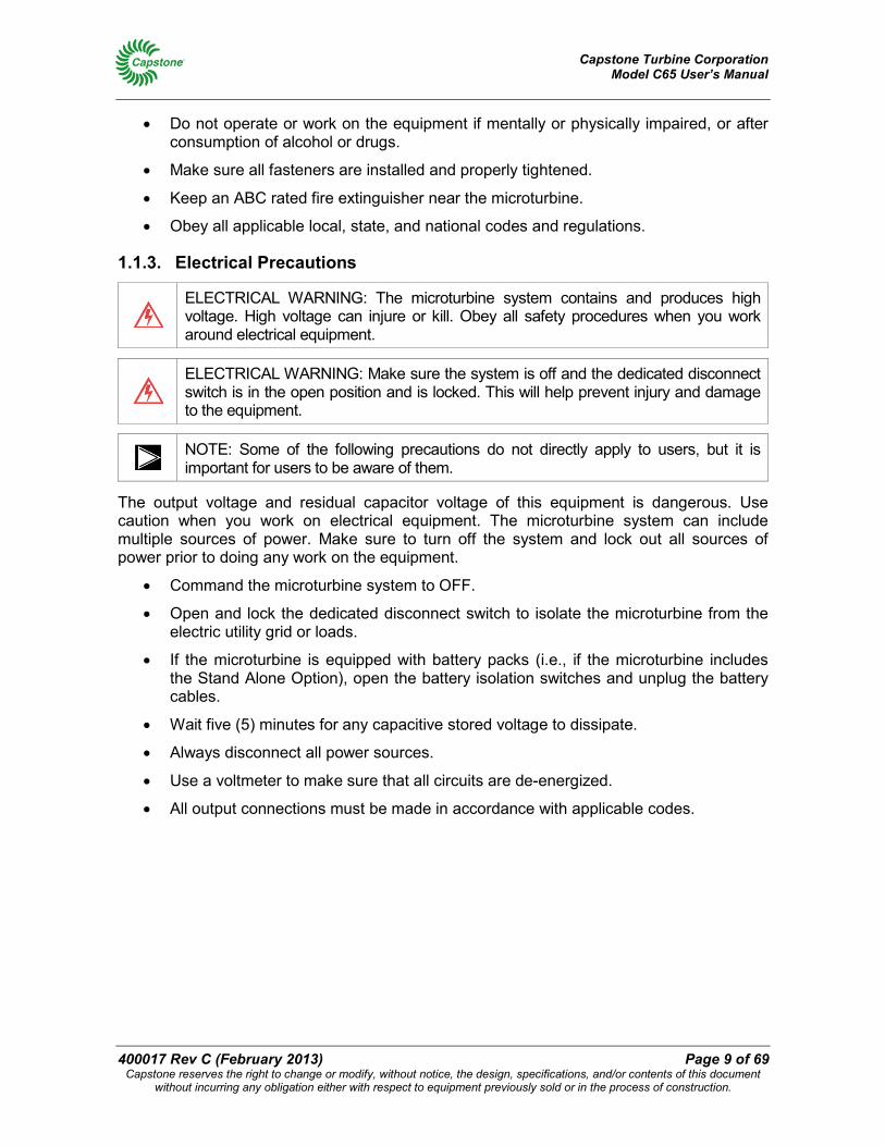
1.1.3. Electrical Precautions
ELECTRICAL WARNING: The microturbine system contains and produces high voltage. High voltage can injure or kill. Obey all safety procedures when you work around electrical equipment.
ELECTRICAL WARNING: Make sure the system is off and the dedicated disconnect switch is in the open position and is locked. This will help prevent injury and damage to the equipment.
NOTE: Some of the following precautions do not directly apply to users, but it is important for users to be aware of them.
The output voltage and residual capacitor voltage of this equipment is dangerous. Use caution when you work on electrical equipment. The microturbine system can include multiple sources of power. Make sure to turn off the system and lock out all sources of power prior to doing any work on the equipment.
• Command the microturbine system to OFF.
• Open and lock the dedicated disconnect switch to isolate the microturbine from the electric utility grid or loads.
• If the microturbine is equipped with battery packs (i.e., if the microturbine includes the Stand Alone Option), open the battery isolation switches and unplug the battery cables.
• Wait five (5) minutes for any capacitive stored voltage to dissipate.
• Always disconnect all power sources.
• Use a voltmeter to make sure that all circuits are de-energized.
• All output connections must be made in accordance with applicable codes.
Capstone Turbine Corporation Model C65 User’s Manual
Page 10 of 69 400017 Rev C (February 2013) Capstone reserves the right to change or modify, without notice, the design, specifications, and/or contents of this document
without incurring any obligation either with respect to equipment previously sold or in the process of construction.
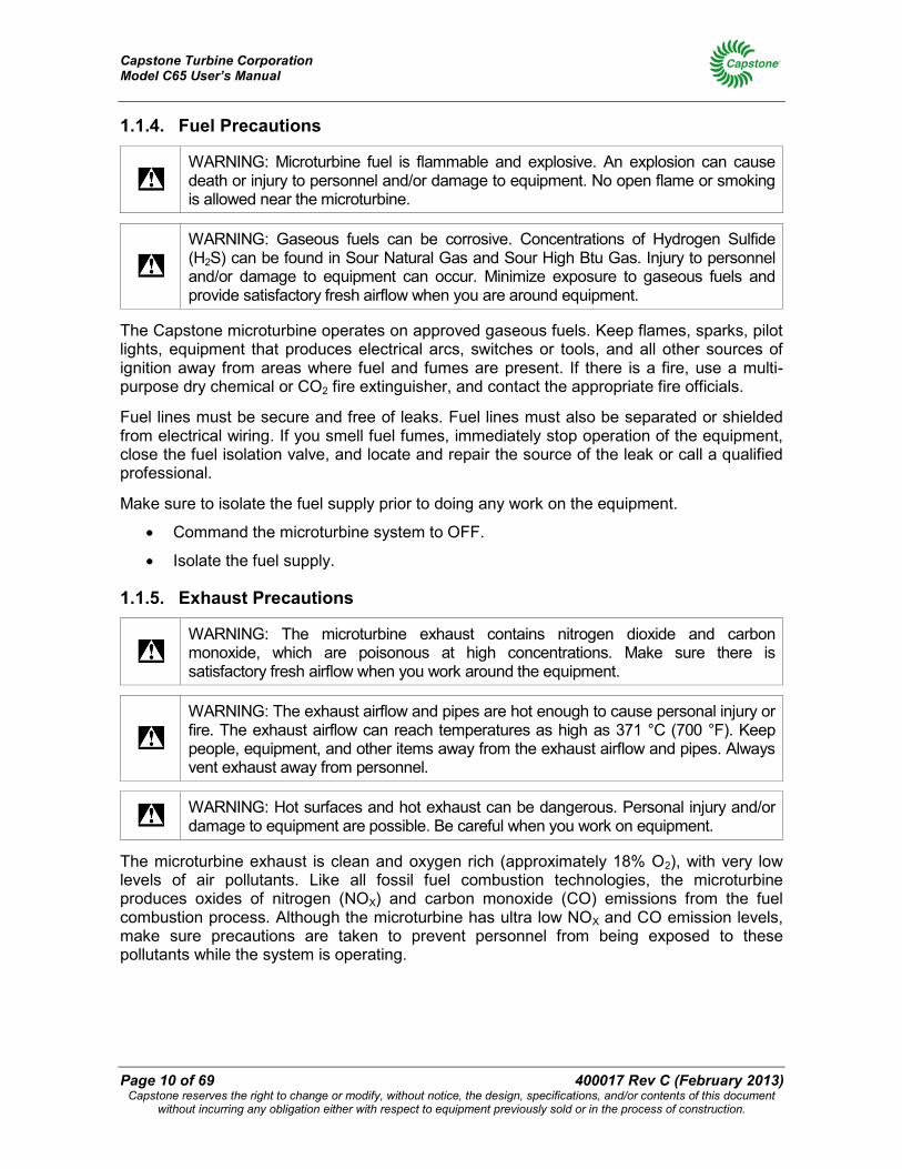
1.1.4. Fuel Precautions
WARNING: Microturbine fuel is flammable and explosive. An explosion can cause death or injury to personnel and/or damage to equipment. No open flame or smoking is allowed near the microturbine.
WARNING: Gaseous fuels can be corrosive. Concentrations of Hydrogen Sulfide (H2S) can be found in Sour Natural Gas and Sour High Btu Gas. Injury to personnel and/or damage to equipment can occur. Minimize exposure to gaseous fuels and provide satisfactory fresh airflow when you are around equipment.
The Capstone microturbine operates on approved gaseous fuels. Keep flames, sparks, pilot lights, equipment that produces electrical arcs, switches or tools, and all other sources of ignition away from areas where fuel and fumes are present. If there is a fire, use a multi-purpose dry chemical or CO2 fire extinguisher, and contact the appropriate fire officials.
Fuel lines must be secure and free of leaks. Fuel lines must also be separated or shielded from electrical wiring. If you smell fuel fumes, immediately stop operation of the equipment, close the fuel isolation valve, and locate and repair the source of the leak or call a qualified professional.
Make sure to isolate the fuel supply prior to doing any work on the equipment.
• Command the microturbine system to OFF.
• Isolate the fuel supply.
1.1.5. Exhaust Precautions
WARNING: The microturbine exhaust contains nitrogen dioxide and carbon monoxide, which are poisonous at high concentrations. Make sure there is satisfactory fresh airflow when you work around the equipment.
WARNING: The exhaust airflow and pipes are hot enough to cause personal injury or fire. The exhaust airflow can reach temperatures as high as 371 °C (700 °F). Keep people, equipment, and other items away from the exhaust airflow and pipes. Always vent exhaust away from personnel.
WARNING: Hot surfaces and hot exhaust can be dangerous. Personal injury and/or damage to equipment are possible. Be careful when you work on equipment.
The microturbine exhaust is clean and oxygen rich (approximately 18% O2), with very low levels of air pollutants. Like all fossil fuel combustion technologies, the microturbine produces oxides of nitrogen (NOX) and carbon monoxide (CO) emissions from the fuel combustion process. Although the microturbine has ultra low NOX and CO emission levels, make sure precautions are taken to prevent personnel from being exposed to these pollutants while the system is operating.
Capstone Turbine Corporation Model C65 User’s Manual
400017 Rev C (February 2013) Page 11 of 69 Capstone reserves the right to change or modify, without notice, the design, specifications, and/or contents of this document
without incurring any obligation either with respect to equipment previously sold or in the process of construction.
When installed indoors, the microturbine exhaust must be vented to the outside. Make sure there is a satisfactory fresh air supply. An exhaust system must be added to direct the exhaust away from the system to reduce the risk of exposure to dangerous emissions.
For exhaust connection data, temperatures, pipe requirements, and other related information, contact your Capstone Authorized Service Provider.
When installed outdoors, the microturbine should be located where there is a satisfactory fresh airflow so the exhaust emissions will be dissipated.
1.1.6. Acoustic Emissions Precautions
The Capstone microturbine is designed to produce safe acoustic emissions. However, when working at a radius of 10 meters (or 33 feet) from an enclosed Capstone microturbine, sound level exposure will average approximately 70 dBA for non-ICHP models and 65 dBA for ICHP models.
Capstone recommends that hearing protection be worn when working on or in the immediate vicinity of operating microturbines for extended time periods.
Other acoustic emissions regulations may apply to your specific installation location. Always check to be certain that your installation complies with all codes required by the local jurisdiction.
1.2. Certifications, Permits, and Codes The Capstone microturbine is designed and manufactured in accordance with a variety of national and international standards. Because the microturbine operates on approved gaseous fuels; installation frequently requires one or more permits from local regulatory agencies. It is not practical to list in the User's Manual the requirements of each authority having jurisdiction and how the Capstone microturbine meets those requirements. For certification data, such as weights, dimensions, required clearances, noise levels, and the Capstone Microturbine Compliance List, please contact your Capstone Authorized Service Provider.
1.3. Output Measurements The measurements presented in this document are in metric units (with U.S. standard units in parentheses). Refer to the sections below for more data.
1.3.1. ISO Conditions
Combustion turbine powered devices (including the Capstone Microturbine) are typically rated at 15 °C (59 °F) at sea level, or 1 atmosphere (1 atm) which is 760 mm Hg (14.696 psia) and identified as International Organization for Standardization (ISO) conditions. For a complete definition of ISO testing conditions, refer to ISO 3977-2.
1.3.2. Pressure
Pressure figures assume gauge pressure, or 1 standard atmosphere (1 atm) 760 mm Hg (14.696 psia) less than absolute pressure, unless otherwise indicated.
Capstone Turbine Corporation Model C65 User’s Manual
Page 12 of 69 400017 Rev C (February 2013) Capstone reserves the right to change or modify, without notice, the design, specifications, and/or contents of this document
without incurring any obligation either with respect to equipment previously sold or in the process of construction.
1.3.3. Volume
Fuel gas and exhaust gas volumetric measurements are given in normalized cubic meters (Nm3) defined at 0 °C (32 °F), and standard cubic feet (SCF) defined at15.6 °C (60 °F). Both volumes are defined at 1 atm (760 mm Hg, 14.696 psia).
1.3.4. Heating Values
Heat contents and heat rates will be found in either Lower Heating Value (LHV) (dry) or Higher Heating Value (HHV), depending upon the application. Capstone calculates heating values at 1 atmosphere (atm) and 15.6 °C (60 °F), according to ASTM D3588.
1.3.5. Microturbine Performance
The microturbine electrical output capability is reduced when operating in higher ambient temperatures or elevations, and by intake or exhaust restrictions. Contact your Capstone Authorized Service Provider for data on performance specifications.
1.3.6. Grid Connect Output
The microturbine electrical output in Grid Connect mode is 3-phase, 400 to 480 VAC and 45 to 65 Hz (both voltage and frequency are determined by the electric utility grid). The connection type for Grid Connect mode is 4-wire Wye with solidly grounded neutral.
1.3.7. Stand Alone Output
When equipped with the Stand Alone option, the electrical output is user adjustable from 150 to 480 Volts AC and from 10 to 60 Hz.
The output power need not be balanced. Loads can be connected in three phases, or single phase and phase-to-phase, or phase-to-neutral, so long as the current limits are respected. A Ramp Start feature can assist in starting loads with large in-rush currents.
1.3.8. Power Quality
The microturbine output conforms to IEEE 519-1992, IEEE Recommended Practices, and Requirements for Harmonic Control in Electrical Power Systems.
1.3.9. Heat Output
The recuperated microturbine can produce up to 591,000 kJ/hr (561,000 Btu/hr) of clean, usable exhaust heat at 309 °C (588 °F). The microturbine exhaust stack diameter is 203 mm (8 in.) in diameter, flowing 0.49 kg/s (1.08 lbm/s).
Contact your Capstone Authorized Service Provider for data on heat output performance for specific system variations and/or ambient conditions.
Capstone Turbine Corporation Model C65 User’s Manual
400017 Rev C (February 2013) Page 13 of 69 Capstone reserves the right to change or modify, without notice, the design, specifications, and/or contents of this document
without incurring any obligation either with respect to equipment previously sold or in the process of construction.
1.4. Referenced Documents The following table contains a list of Capstone documents referenced in this User’s Manual.
Document Part No Description 410001 Model C65 Electrical Technical Reference 410027 Grid Connect Operation Technical Reference 410028 Stand Alone Operation Technical Reference 410032 MultiPac Operation Technical Reference 410033 Protective Relay Functions 410043 C65 Integrated CHP Technical Reference 410058 Gas Pack Technical Reference 410065 MicroTurbine Systems Emissions Technical Reference 440000 Standard Maintenance Schedule Work Instructions 460044 C65 Product Specification 460061 C65 CARB Product Specification 480010 C30/C65 Offshore and Hazardous Location Application Guide 480014 C65 Integrated CHP Application Guide 522409 C65 ICHP CARB Outline and Installation (O&I) Drawing 522954 C65 Low Emissions O&I Drawing 528556 C65 ICHP O&I Drawing 528633 C65 Industrial Package O&I Drawing
Capstone Turbine Corporation Model C65 User’s Manual
Page 14 of 69 400017 Rev C (February 2013) Capstone reserves the right to change or modify, without notice, the design, specifications, and/or contents of this document
without incurring any obligation either with respect to equipment previously sold or in the process of construction.
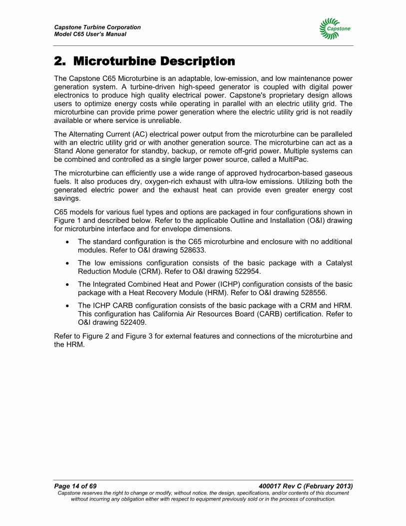
2. Microturbine Description The Capstone C65 Microturbine is an adaptable, low-emission, and low maintenance power generation system. A turbine-driven high-speed generator is coupled with digital power electronics to produce high quality electrical power. Capstone's proprietary design allows users to optimize energy costs while operating in parallel with an electric utility grid. The microturbine can provide prime power generation where the electric utility grid is not readily available or where service is unreliable.
The Alternating Current (AC) electrical power output from the microturbine can be paralleled with an electric utility grid or with another generation source. The microturbine can act as a Stand Alone generator for standby, backup, or remote off-grid power. Multiple systems can be combined and controlled as a single larger power source, called a MultiPac.
The microturbine can efficiently use a wide range of approved hydrocarbon-based gaseous fuels. It also produces dry, oxygen-rich exhaust with ultra-low emissions. Utilizing both the generated electric power and the exhaust heat can provide even greater energy cost savings.
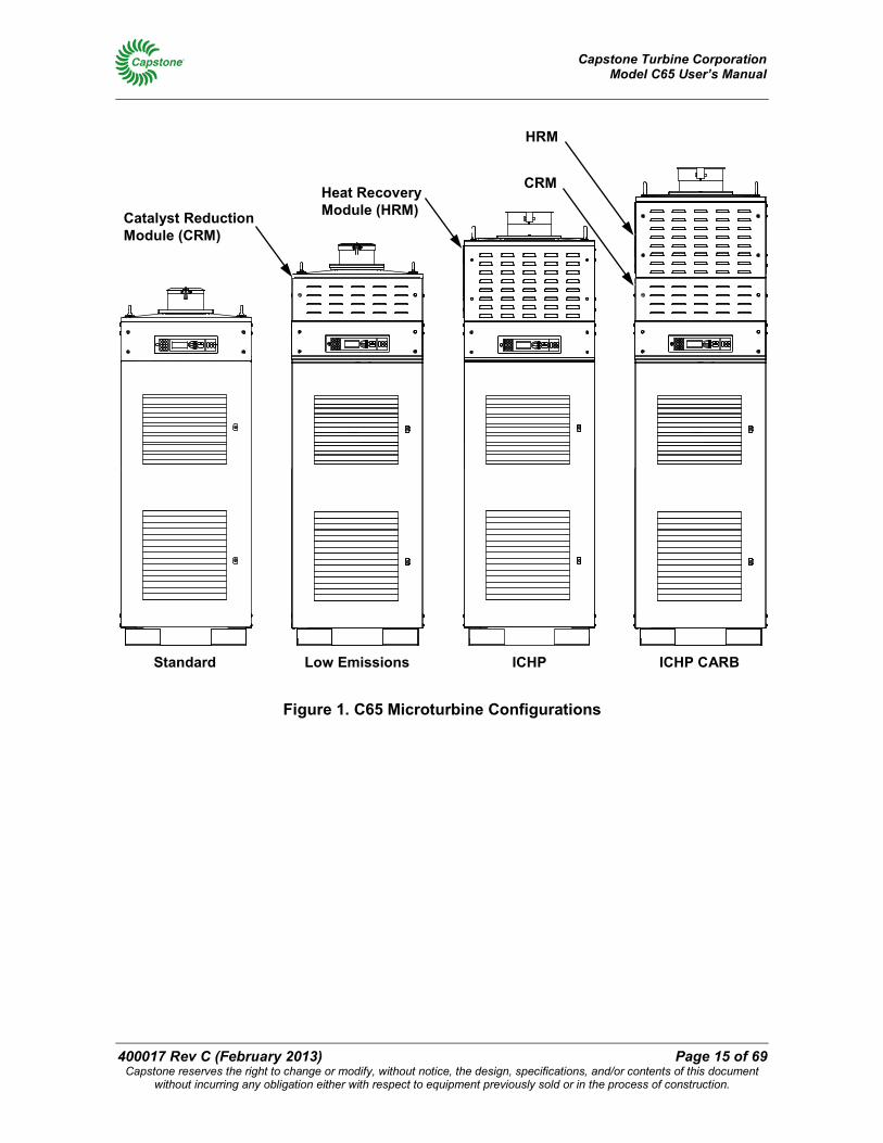
C65 models for various fuel types and options are packaged in four configurations shown in Figure 1 and described below. Refer to the applicable Outline and Installation (O&I) drawing for microturbine interface and for envelope dimensions.
• The standard configuration is the C65 microturbine and enclosure with no additional modules. Refer to O&I drawing 528633.
• The low emissions configuration consists of the basic package with a Catalyst Reduction Module (CRM). Refer to O&I drawing 522954.
• The Integrated Combined Heat and Power (ICHP) configuration consists of the basic package with a Heat Recovery Module (HRM). Refer to O&I drawing 528556.
• The ICHP CARB configuration consists of the basic package with a CRM and HRM. This configuration has California Air Resources Board (CARB) certification. Refer to O&I drawing 522409.
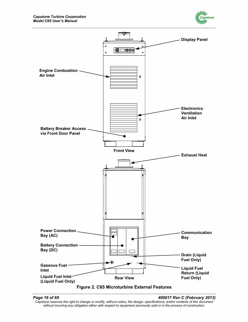
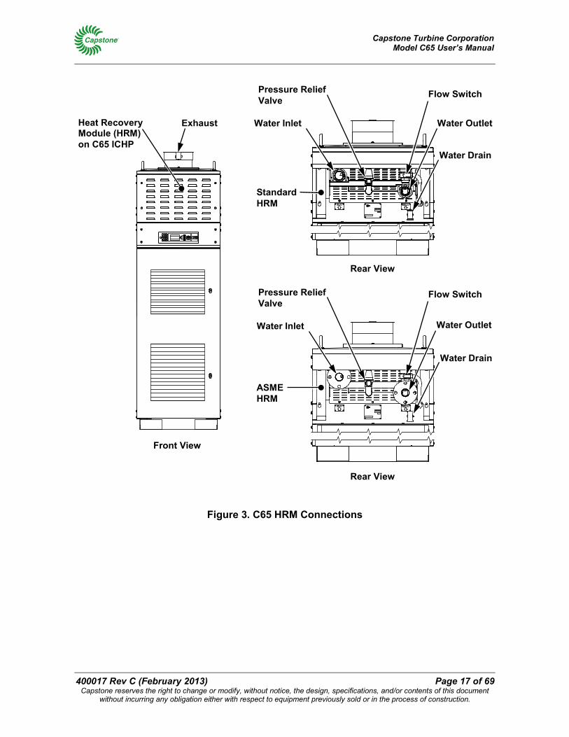
Refer to Figure 2 and Figure 3 for external features and connections of the microturbine and the HRM.
Capstone Turbine Corporation Model C65 User’s Manual
400017 Rev C (February 2013) Page 15 of 69 Capstone reserves the right to change or modify, without notice, the design, specifications, and/or contents of this document
without incurring any obligation either with respect to equipment previously sold or in the process of construction.
Figure 1. C65 Microturbine Configurations
Standard Low Emissions ICHP ICHP CARB
Catalyst Reduction Module (CRM)
Heat Recovery Module (HRM)
CRM
HRM
Capstone Turbine Corporation Model C65 User’s Manual
Page 16 of 69 400017 Rev C (February 2013) Capstone reserves the right to change or modify, without notice, the design, specifications, and/or contents of this document
without incurring any obligation either with respect to equipment previously sold or in the process of construction.
Figure 2. C65 Microturbine External Features
Display Panel
Engine Combustion Air Inlet
Electronics Ventilation Air Inlet
Exhaust Heat
Battery Breaker Access via Front Door Panel
Liquid Fuel Return (Liquid Fuel Only)
Power Connection Bay (AC)
Communication Bay
Liquid Fuel Inlet (Liquid Fuel Only)
Drain (Liquid Fuel Only)
Gaseous Fuel Inlet
Battery Connection Bay (DC)
Front View
Rear View
Capstone Turbine Corporation Model C65 User’s Manual
400017 Rev C (February 2013) Page 17 of 69 Capstone reserves the right to change or modify, without notice, the design, specifications, and/or contents of this document
without incurring any obligation either with respect to equipment previously sold or in the process of construction.
Figure 3. C65 HRM Connections
Heat Recovery Module (HRM) on C65 ICHP
Water Inlet
Pressure Relief Valve
Water Drain
Water Outlet
Front View
Rear View
Flow Switch
Water Inlet
Pressure Relief Valve
Water Drain
Water Outlet
Flow Switch
Exhaust
Standard HRM
ASME HRM
Rear View
Capstone Turbine Corporation Model C65 User’s Manual
Page 18 of 69 400017 Rev C (February 2013) Capstone reserves the right to change or modify, without notice, the design, specifications, and/or contents of this document
without incurring any obligation either with respect to equipment previously sold or in the process of construction.
2.1. User Interface
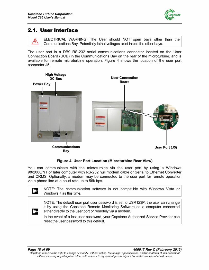
ELECTRICAL WARNING: The User should NOT open bays other than the Communications Bay. Potentially lethal voltages exist inside the other bays.
The user port is a DB9 RS-232 serial communications connector located on the User Connection Board (UCB) in the Communications Bay on the rear of the microturbine, and is available for remote microturbine operation. Figure 4 shows the location of the user port connector J5.
Figure 4. User Port Location (Microturbine Rear View)
You can communicate with the microturbine via the user port by using a Windows 98/2000/NT or later computer with RS-232 null modem cable or Serial to Ethernet Converter and CRMS. Optionally, a modem may be connected to the user port for remote operation via a phone line at a baud rate up to 56k bps.
NOTE: The communication software is not compatible with Windows Vista or Windows 7 as this time.
NOTE: The default user port user password is set to USR123P; the user can change it by using the Capstone Remote Monitoring Software on a computer connected either directly to the user port or remotely via a modem. In the event of a lost user password, your Capstone Authorized Service Provider can reset the user password to this default.
Power Bay
Communications Bay
User Connection Board
User Port (J5)
High Voltage DC Bus
Capstone Turbine Corporation Model C65 User’s Manual
400017 Rev C (February 2013) Page 19 of 69 Capstone reserves the right to change or modify, without notice, the design, specifications, and/or contents of this document
without incurring any obligation either with respect to equipment previously sold or in the process of construction.
2.2. Microturbine Features The various features of the Capstone Microturbine are listed below:
• A state-of-the-art digital power controller with built-in protective relay functions provides two output choices:
o Built-in synchronous AC
o Stand Alone AC output (optional)
• Patented air bearings eliminate the need for oil or other liquid lubricants.
• Air-cooled design of the entire system (turbine and controller) eliminates the need for liquid coolants.
• The engine has only one moving part. No gears, belts, or turbine-driven accessories.
• Advanced combustion control eliminates the need for ceramics or for other costly materials or for catalytic combustion, and provides ultra-low emissions.
• The integral annular recuperator (heat exchanger) doubles thermal efficiency.
• Digital control technology facilitates advanced control or Ethernet monitoring, and diagnostic capabilities, both on-board and remotely.
2.2.1. Microturbine Engine
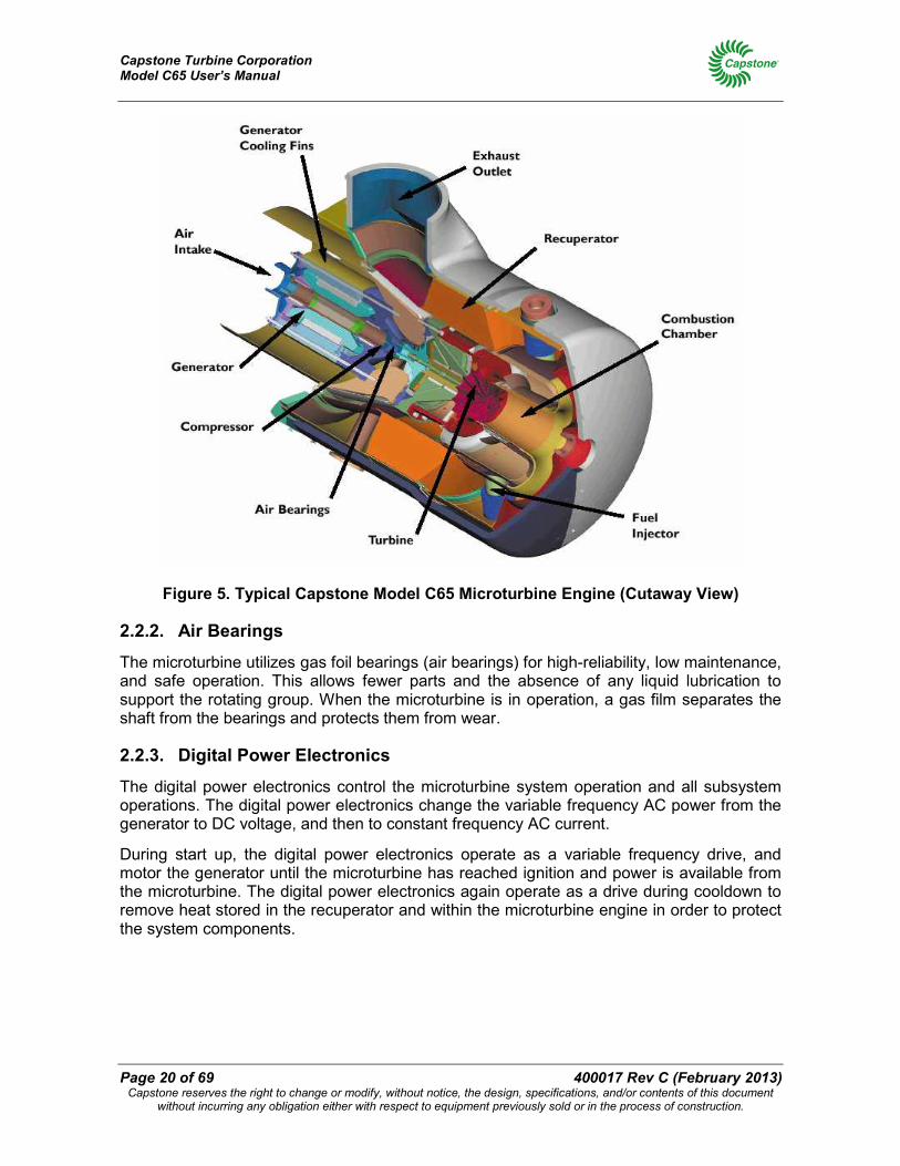
The microturbine engine is a combustion turbine that includes a compressor, combustor, turbine, generator, and a recuperator. The rotating components are mounted on a single shaft supported by patented air bearings and spin at up to 96,000 RPM. The permanent magnet generator is cooled by the airflow into the microturbine. The output of the generator is variable voltage, variable frequency AC. The generator is used as a motor during start-up and cooldown cycles.
The key mechanical components that make up the Capstone Microturbine engine are shown in Figure 5.
Capstone Turbine Corporation Model C65 User’s Manual
Page 20 of 69 400017 Rev C (February 2013) Capstone reserves the right to change or modify, without notice, the design, specifications, and/or contents of this document
without incurring any obligation either with respect to equipment previously sold or in the process of construction.
Figure 5. Typical Capstone Model C65 Microturbine Engine (Cutaway View)
2.2.2. Air Bearings
The microturbine utilizes gas foil bearings (air bearings) for high-reliability, low maintenance, and safe operation. This allows fewer parts and the absence of any liquid lubrication to support the rotating group. When the microturbine is in operation, a gas film separates the shaft from the bearings and protects them from wear.
2.2.3. Digital Power Electronics
The digital power electronics control the microturbine system operation and all subsystem operations. The digital power electronics change the variable frequency AC power from the generator to DC voltage, and then to constant frequency AC current.
During start up, the digital power electronics operate as a variable frequency drive, and motor the generator until the microturbine has reached ignition and power is available from the microturbine. The digital power electronics again operate as a drive during cooldown to remove heat stored in the recuperator and within the microturbine engine in order to protect the system components.
Capstone Turbine Corporation Model C65 User’s Manual
400017 Rev C (February 2013) Page 21 of 69 Capstone reserves the right to change or modify, without notice, the design, specifications, and/or contents of this document
without incurring any obligation either with respect to equipment previously sold or in the process of construction.
2.2.4. Fuel System
The microturbine can efficiently use a wide range of approved hydrocarbon-based gaseous fuels, depending on the model. The microturbine includes an integral fuel delivery and control system. The available microturbine models include the following fuel types:
• High pressure natural gas (HPNG)
• High pressure sour gas (HPSG)
• Landfill gas
• Digester gas
• Liquid fuel
• Propane (HD-5)
NOTE: Low pressure natural gas (LPNG) capability is provided by means of the Capstone accessory (Gas Pack) or a third part compressor. (Refer to Gas Pack Technical Reference 410058.)
Contact your Capstone Authorized Service Provider for data on approved fuels and performance specifications.
2.2.5. Emissions
The Capstone Microturbine is designed to produce very clean emissions. The exhaust is clean and oxygen rich (approximately 18% O2) with very low levels of air pollutants. Like all fuel combustion technology, the microturbine produces emissions (like nitrogen dioxide and carbon monoxide) from the fuel combustion process. The microturbine has ultra low nitrogen dioxide (NO2) and carbon monoxide (CO) emission levels. Refer to the Emissions Technical Reference (410065) for detailed emission specifications.
The C65 Low Emissions microturbine includes a Catalyst Reduction Module (CRM) to provide further reduction of CO emissions. In addition, the C65 CARB models meet the emission requirements of the California Air Resources Board (CARB). The ICHP CARB microturbine incorporates a Heat Recovery Module (HRM) as well as CRM to satisfy the 2007 Fossil Fuel Emissions Standards for CARB certification. Capstone also offers CARB-certified C65 models that burn waste gas. Refer to the C65 Product Specification (460044) for details about the Low Emissions configuration. Refer to the C65 CARB Product Specification (460061) for a description of Capstone C65 CARB models.
2.2.6. Enclosure
The microturbine standard enclosure is designed for indoor and outdoor use, and conforms to NEMA 3R requirements. Capstone components for Original Equipment Manufacturer (OEM) use can be provided with or without a mounting frame.
The C65 hazardous location microturbine has a stainless steel pressurized enclosure, which houses the microturbine system, and is certified for Class I, Division 2 (CID2), or Class I, Zone 2 (CIZ2) environments. Refer to the C30/C65 Offshore and Hazardous Location Application Guide (480010) for details.
Capstone Turbine Corporation Model C65 User’s Manual
Page 22 of 69 400017 Rev C (February 2013) Capstone reserves the right to change or modify, without notice, the design, specifications, and/or contents of this document
without incurring any obligation either with respect to equipment previously sold or in the process of construction.
2.2.7. Integrated Combined Heating and Power (ICHP)
This option is known as Integrated Combined Heat and Power (ICHP) because the Heat Recovery Module (HRM) is installed on the C65 microturbine and integrated with its communication electronics. The HRM includes an exhaust heat recovery unit and an exhaust diverter to allow full or partial recovery of exhaust energy. The ICHP system includes microprocessor control with input/output functions to allow application in a wide variety of heat recovery uses. Refer to the C65 Integrated CHP Technical Reference (410043) and C65 Integrated CHP Application Guide (480014) for details.
ICHP allows the user to realize the benefits of usable electrical and thermal power from a single fuel source. The electricity provides on-site power generation, and the heat offsets or replaces local thermal loads such as space heating, pool heating and industrial process hot water. In addition, the oxygen-rich exhaust together with ultra-low emissions makes the direct exhaust applicable for some food processing and greenhouse uses, such as heating, cooling (by absorption), dehumidifying, baking, or drying. Contact your Capstone Authorized Service Provider for details.
2.2.8. Hazardous Location Option
The hazardous location option enables use of the C65 microturbine in hazardous (CID2 or CIZ2) environments such as offshore oil platforms. It also provides for extended operation in high humidity environments. The stainless steel pressurized enclosure contains equipment to maintain correct pressurization, monitor gas and heat levels, and prevent corrosion. The hazardous location option is available as a Dual Mode (battery equipped) model for Stand Alone operation only. The battery contains internal contactors that are controlled remotely so that it can be completely disconnected during the purge cycle and in the event of a safety shutdown. Refer to the C30/C65 Offshore and Hazardous Location Application Guide (480010) for details.
2.2.9. Offshore Option
The offshore option enables use of the C65 microturbine in high humidity environments, including offshore oil platforms, but only in areas classified as non-hazardous. The offshore option contains heaters and specially treated electrical connectors to prevent corrosion. This option is available as a Dual Mode (battery equipped) model for Stand Alone operation only. The battery pack (with internal contactors) and fuel shutoff valve are operated by a hazardous location controller to ensure isolation on a shutdown. Refer to the C30/C65 Offshore and Hazardous Location Application Guide (480010) for details.
2.2.10. Capstone Remote Monitoring Software
Capstone Remote Monitoring Software (CRMS) is the optional Capstone proprietary software that can operate and control the microturbine from the RS-232 user port. This allows communication interface devices (a laptop plugged in with a null-modem cable or Serial to Ethernet Converter or a remote computer via a modem) to communicate via the RS-232 port.
CRMS is an easy to use, menu driven Windows-based software for a remote computer to monitor and control the Capstone Microturbine. The software can control from 1 to 30 microturbine systems, by direct connection or remotely via a modem. Copies of and licenses for this software are available for purchase from Capstone.
Capstone Turbine Corporation Model C65 User’s Manual
400017 Rev C (February 2013) Page 23 of 69 Capstone reserves the right to change or modify, without notice, the design, specifications, and/or contents of this document
without incurring any obligation either with respect to equipment previously sold or in the process of construction.
2.2.11. Grid Connect Mode
When connected to a utility grid (Grid Connect mode), the microturbine operates according to three available dispatch modes: Base Loading, Load Following, and Time of Use. These dispatch modes are described in the following paragraphs.
2.2.11.1. Base Loading
Base Loading is the default dispatch mode for the microturbine in Grid Connect operation. In this mode, the microturbine generates power up to the value of the stored power demand, and the electric utility grid provides the remaining power to meet the total customer load.
2.2.11.2. Load Following
Load Following is implemented in applications where the microturbine produces more power than the customer facility can use. A setting called Utility Power Setpoint is used to fix the power provided by the utility grid until the microturbine reaches its power capacity. The Utility Power Setpoint also acts as a buffer to allow the microturbine to react to large swings in the facility load.
2.2.11.3. Time of Use
The Time of Use mode allows the microturbine user to selectively determine start/stop commands and/or power output levels for up to 20 timed events. Events are programmed by day of week, time of day, and power demand. When the microturbine is operating, the programmed events occur in sequential order according to the time of day. This enables efficient use of the microturbine to supplement power only during periods of the day when electricity from the utility is at a premium.
2.2.12. Dual Mode
The C65 Dual Mode microturbine includes a large battery pack used for unassisted start and for transient electrical load management, as well as a power converter and battery management system. The battery pack is a lead-acid type and completely sealed.
The Dual Mode model can function in Stand Alone mode to power connected loads at user selected voltage and frequency setpoints. It can power remote facilities such as construction sites, oil fields, offshore platforms, and other locations where the electric utility grid is not available.
With the Dual Mode System Controller (DMSC), the microturbine can be used for both Grid Connect power and Stand Alone power applications. The microturbine can be programmed to switch automatically upon loss/restoration of electric utility grid power.
2.2.13. MultiPac Power
C65 microturbines can be installed in groups of up to 20 units using a standard Capstone MultiPac communications cable. This MultiPac capability enables connected microturbines to operate as a single power generation source. A MultiPac configuration features a single control point and synchronous voltage and frequency output for all units. Individual microturbines share power, current, and load on both a dynamic and steady state basis. An optional Capstone Advanced Power Server (APS) can be used to manage the power distribution for up to 30 microturbines.
Capstone Turbine Corporation Model C65 User’s Manual
Page 24 of 69 400017 Rev C (February 2013) Capstone reserves the right to change or modify, without notice, the design, specifications, and/or contents of this document
without incurring any obligation either with respect to equipment previously sold or in the process of construction.
3. Microturbine Operation The following paragraphs provide instructions required for the operation of the Capstone C65 Microturbine. Refer to Using the Display Panel on page 37 for details about operating the microturbine via the display panel.
3.1. Basic Microturbine Operation Most microturbine applications require no regular interaction with an operator during normal operation. Built-in dispatch features include peak shaving with local or remote control, external switch control, programmable scheduling, automatic restart, and automatic loading.
Applications with the C65 hazardous location microturbine require the use of the Capstone hazardous location controller to monitor external inputs such as gas detection and pressure sensing and to intelligently control normal operation. The hazardous location microturbine operates in Stand Alone mode only, but all built-in microturbine dispatch modes remain the same, except for auto restart functionality, which is unavailable. Refer to the C30/C65 Offshore and Hazardous Location Application Guide (480010) for details.
3.1.1. Communications
There are two ways communicate with the microturbine, either (1) via manual operation of the display panel, or (2) via digital communications through the user port or maintenance port on the UCB. Refer to Using the Display Panel on page 37 for details about display panel operation.
A PC may be connected to the user port directly (with an RS-232 null modem cable or using a Serial-to-Ethernet converter) or via a phone line and optional modem. Communication is then possible by use of Capstone's open communication protocol.
The setup, control, and basic performance of the microturbine can be monitored and adjusted through the user or maintenance port on the UCB.
Primary user communications include:
• Start and stop functions
• Adjustment of power output
• Storage and display of operation history
• The configuration of operational parameters
• Battery management functions
Capstone Turbine Corporation Model C65 User’s Manual
400017 Rev C (February 2013) Page 25 of 69 Capstone reserves the right to change or modify, without notice, the design, specifications, and/or contents of this document
without incurring any obligation either with respect to equipment previously sold or in the process of construction.
3.1.2. Operational Data
The display panel (or a computer connected directly or via modem) can be used to monitor many operational parameters during system operation. Only some of the routine operation and performance data items available for monitoring are listed below:
• Power Output (in kilowatts, or kW)
• Turbine Speed (in revolutions per minute or RPM)
• Turbine Exit Temperature (in °C or °F)
• Phase Voltages (in Volts) and Currents (in Amperes)
3.1.3. Control Device Authority and Priority
A PC connected to the user or maintenance port can function as a control device for the microturbine. A PC can view system data at any time, but only one device can control the microturbine operation (that is, providing start/stop command or changes to power demand).
The display panel has default control authority to issue operational commands to the microturbine. The user can start and stop the microturbine without logging on to the system (that is, no password is required). All other system adjustments require the user to log on to the system with the user password.
The user port will take control when a password is entered either from the Capstone Remote Monitoring Software (CRMS) or other software using the Capstone open communication protocol.
All system commands via the user port, such as start, stop, and adjustment of Power Demands, require entry of a user password. When the user port has control, the Display Panel does not have control and can only be used to view information. The system automatically cancels a log on after five minutes of inactivity.
3.1.4. Startup
A Start command can be issued from the display panel or remotely through a PC/CRMS interface. When the command has been issued, the generator operates as a motor to bring the microturbine up to ignition speed, at which point fuel is introduced into the combustion chamber and ignited. When the Turbine Exit Temperature (TET) sensors detect an increase in temperature, the system is declared lit, and the microturbine accelerates. Once the MT enters the load state, it accelerates to full load. The start-up process from a cold start to full load requires approximately six minutes. The startup process can take longer for a Stand Alone MT, which can take as long as 20 minutes to recharge the battery packs to the level needed for full load operation.
3.1.5. Shutdown
When the microturbine is issued a Stop command, power output is reduced, followed by a period that the microturbine is motored at nominal speed to remove heat stored in the recuperator and microturbine engine in order to protect the system components.
Capstone Turbine Corporation Model C65 User’s Manual
Page 26 of 69 400017 Rev C (February 2013) Capstone reserves the right to change or modify, without notice, the design, specifications, and/or contents of this document
without incurring any obligation either with respect to equipment previously sold or in the process of construction.
The overall cooldown period is up to ten minutes, but is affected by microturbine model and temperature at shutdown. A restart may be attempted at any time, and a start will occur after completion of the initial cooldown period. Auto Restart is not available for hazardous location microturbines with pressurized enclosures.
If the Stand Alone battery requires a recharge (after a stop command is issued), the microturbine will continue to operate with fuel in order to recharge the battery. The microturbine will enter the cool down period after the battery has reached a 90 to 95% state of charge. The battery can require as long as 20 minutes to recharge after a stop command has been issued before entering cooldown. This will be followed by a cooldown period of up to 10 minutes.
3.1.6. Emergency Stop (E-Stop)
The UCB contains input pins to which the user can connect an Emergency Stop (E-Stop) device. The E-Stop function enables the safe and immediate shut down of the microturbine in the event of an emergency. Activation of the E-Stop immediately shuts off fuel and electrical output. This will cause the compressor bypass valve to open, vent the compressed air out of the microturbine, and the turbine will coast to a stop.
After an emergency stop, the power to the microturbine must be turned off for 30 seconds before a restart can be attempted. Emergency stops should NEVER be used for routine shutdowns. Emergency stops increase stress on the system components and will result in reduced service life of the microturbine.
CAUTION: Repeated use of the optional Emergency Stop switch will result in damage to the microturbine. Use only in emergency situations.
Also, after an emergency stop, you may want to close the external fuel isolation valve to shut off any additional fuel flow into the microturbine. The external fuel isolation valve must be returned to the open position before a restart of the microturbine is attempted.
3.1.7. Restart
The microturbine system can normally be restarted after a shutdown, while the battery recharges, or during the cool down period before the speed of the microturbine reaches zero. This allows for faster power output and helps to eliminate wear on the bearings.
3.2. Grid Connect Operation
NOTE: Grid Connect operation is not available for the hazardous location microturbine.
The microturbine in Grid Connect operation allows electric utilities to expand generating capacity in small increments. This optimizes current infrastructure and reduces the need to upgrade specific site capacity and lowers overall costs. Refer to the Grid Connect Operation Technical Reference (410027) for details.
Capstone Turbine Corporation Model C65 User’s Manual
400017 Rev C (February 2013) Page 27 of 69 Capstone reserves the right to change or modify, without notice, the design, specifications, and/or contents of this document
without incurring any obligation either with respect to equipment previously sold or in the process of construction.
3.2.1. Grid Connect Dispatch
Operation of the Capstone Microturbine in parallel with an electric utility grid consists only of commanding the system on or off, and commanding an output power level. In most configurations these commands are mostly or entirely automated in various ways termed dispatch modes.
NOTE: If grid power is removed for any reason, the auto restart dispatch mode can automatically command the system ON when grid power is restored.
3.2.2. Configuring Grid Connect
To configure the microturbine for Grid Connect operation it is necessary to enable the Grid Connect Interlock and then command the system to Grid Connect mode either through the Display Panel or RS-232 commands via the user port.
3.2.3. Grid Connect Interlock
The Grid Connect Interlock consists of a pair of 5-Volt dry circuit contact terminals located on the User Connection Board. A low resistance closed circuit between these terminals permits Grid Connect operation, opening the circuit disallows Grid Connect operation. The terminals are found in the Communications Bay at the rear of the microturbine enclosure. Your Capstone Authorized Service Provider should make this electrical connection.
3.2.4. Grid Connect Mode Enable
To enable the Grid Connect mode, the microturbine must be correctly connected to a suitable live electric utility grid and the Grid Connect Interlock must be closed. Your Capstone Authorized Service Provider should make this electrical connection.
To enable the Grid Connect mode from the Display Panel, requires logging on with a password; then navigate to the System Data menu, then to the System Configuration submenu, and then to the Power Connect submenu. Select Grid Connect mode and then press the ACCEPT button. If the Grid Connect Interlock is open, the system will accept the command but post a GC Interlock fault, prohibiting a start.
3.2.5. Starting a Grid Connect System
The microturbine system in Grid Connect mode must be commanded to start. Even if the system is configured for automatic operation, the initial START command is required to enable the automatic mode. If the Auto Restart feature is enabled, the ON command is stored by the system even through a loss of Grid Power.
To start the system from the Display Panel, press and hold the INTERLOCK button, and then press the START button. (If your microturbine has been configured with a remote start/stop switch, simply set the switch to Start or On to start the system.)
3.2.6. Stopping a Grid Connect System
The microturbine system can be stopped at any time. In Grid Connect operation, an OFF command will override any dispatch mode settings, and is stored by the system.
Capstone Turbine Corporation Model C65 User’s Manual
Page 28 of 69 400017 Rev C (February 2013) Capstone reserves the right to change or modify, without notice, the design, specifications, and/or contents of this document
without incurring any obligation either with respect to equipment previously sold or in the process of construction.
The shutdown process includes a cool down period, which can last up to 10 minutes, depending on the operating temperature at shutdown. During the cool down cycle, the power output is reduced and fuel supply is off but the microturbine continues to rotate to dissipate excess heat.
A restart can be attempted at any time during a cool down period.
To stop the system from the Display Panel, press and hold the INTERLOCK button, and then press the STOP button. (If your microturbine has been configured with a remote start/stop switch, simply set the switch to Stop or Off to stop the system.)
3.2.7. Grid Connect Power Demand
In Grid Connect operation, the microturbine system must be commanded to a specific output power level. Each dispatch mode includes a power level setting. Some dispatch modes include automatic output power level changes.
3.3. Stand Alone Operation Stand Alone operation provides power to remote facilities such as construction sites, offshore oil platforms, or other locations where the electric utility grid is not available.
It requires the battery-equipped Dual Mode model or hazardous location microturbine. Stand Alone operation consists of commanding the system on or off, and then enabling or disabling the power output. These commands can be automated. Refer to the Stand Alone Operation Technical Reference (410028) for details.
3.3.1. Configuring Stand Alone
To configure the microturbine for Stand Alone operation it is necessary to enable the Stand Alone Interlock and then configure the system to Stand Alone mode. through the display panel or RS-232 commands over the remote communications interface via the user port.
3.3.2. Stand Alone Interlock
The Stand Alone Interlock consists of a pair of 5 Volt dry circuit contact terminals. A low resistance closed circuit between these terminals permits Stand Alone operation. An opened circuit prevents Stand Alone operation. The terminals are found in the Communications Bay at the rear of the microturbine enclosure. Your Capstone Authorized Service Provider should make this electrical connection.
3.3.3. Stand Alone Mode Enable
To enable Stand Alone mode, the microturbine must be powered on (set the Stand Alone battery isolation switch to ON) and the Stand Alone Interlock closed. To enable Stand Alone mode from the display panel logon with a password; then navigate to the System Data menu, System Configuration submenu, and the Power Connect submenu. Select Stand Alone mode, then press the ACCEPT button. If the Stand Alone Interlock is open, the system will accept the command but post a SA Interlock fault. If no battery is detected, an internal No Battery fault will be reported.
Capstone Turbine Corporation Model C65 User’s Manual
400017 Rev C (February 2013) Page 29 of 69 Capstone reserves the right to change or modify, without notice, the design, specifications, and/or contents of this document
without incurring any obligation either with respect to equipment previously sold or in the process of construction.
3.3.4. Stand Alone Battery
A microturbine configured for Stand Alone operation includes a large battery pack that stores energy for microturbine startup when disconnected from the electric utility grid. It also provides an electrical buffer for sudden increases or decreases in load during Stand Alone operation. Management of the battery and its state of charge is automatic within the microturbine. An awareness of these battery management functions will promote an understanding of why the system may appear to behave autonomously. For example, the microturbine will always attempt to fully recharge the battery after a user commanded shut down and before the microturbine enters the cool down state.
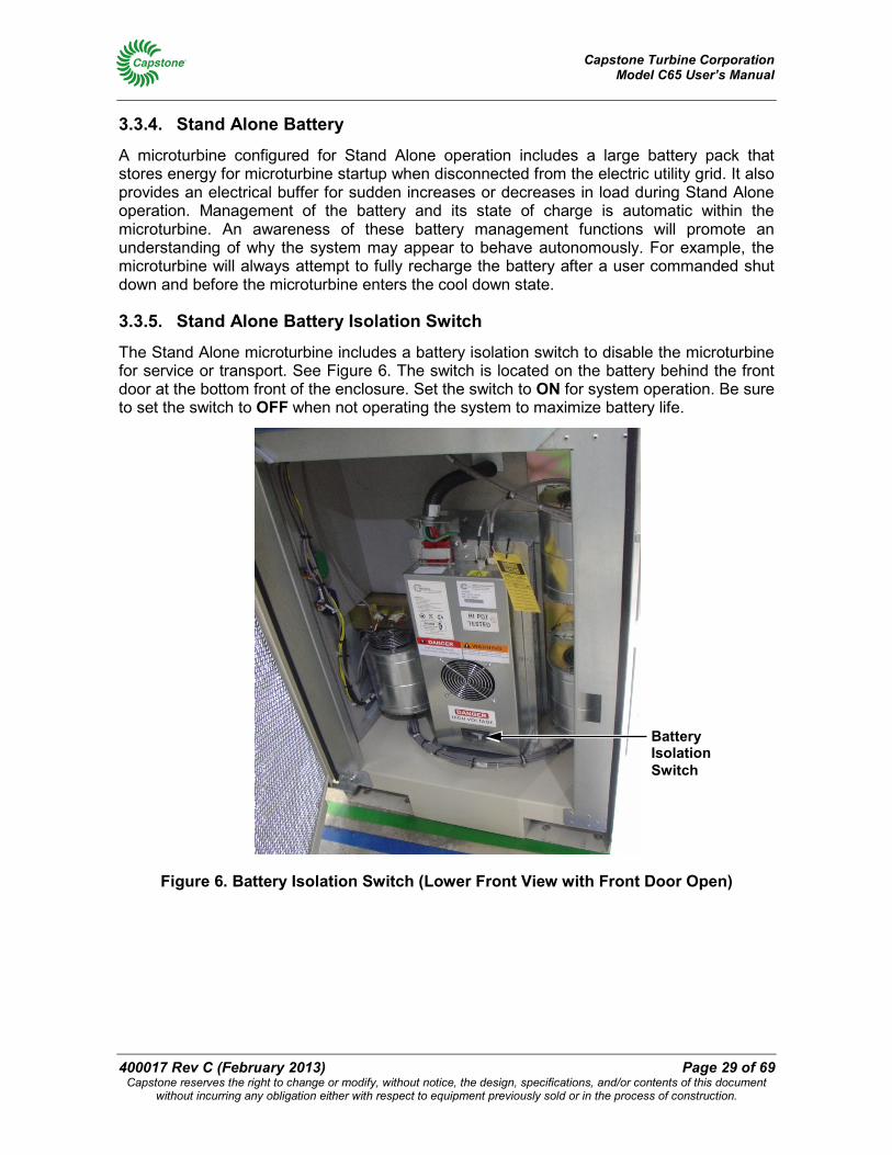
3.3.5. Stand Alone Battery Isolation Switch
The Stand Alone microturbine includes a battery isolation switch to disable the microturbine for service or transport. See Figure 6. The switch is located on the battery behind the front door at the bottom front of the enclosure. Set the switch to ON for system operation. Be sure to set the switch to OFF when not operating the system to maximize battery life.
Figure 6. Battery Isolation Switch (Lower Front View with Front Door Open)
Battery Isolation Switch
Capstone Turbine Corporation Model C65 User’s Manual
Page 30 of 69 400017 Rev C (February 2013) Capstone reserves the right to change or modify, without notice, the design, specifications, and/or contents of this document
without incurring any obligation either with respect to equipment previously sold or in the process of construction.
3.3.6. System Sleep in Stand Alone Mode
Reducing battery draw to near zero during prolonged periods of non-use can extend the microturbine battery charge significantly. This is called Sleep Mode. Sleep Mode is automatic, but the time of inactivity can be adjusted using CRMS. If the battery isolation switch is set to ON, and the Display Panel is dark, the system is most likely in Sleep Mode. In Sleep Mode, the battery pack needs to be recharged periodically. Refer to the section on Battery Maintenance for more data on recharging the Battery.
3.3.7. Waking a Stand Alone Microturbine
If the Stand Alone system is in Sleep Mode, pressing the BATT START button at the far left of the Display Panel (for 2 seconds or less) will wake it up. If communicating with the microturbine remotely using a modem, the modem ring indicator will wake up a sleeping Stand Alone system.
CAUTION: Permanent closure of the battery start contacts (in the following paragraph) will completely discharge the UCB battery. Therefore, the battery start contacts may only be closed for a period of 0.1 to 2.0 seconds.
Alternately, momentarily closing the battery start contacts in the communication bay will wake up the system. This must be a momentary closure of 0.1 to 2.0 seconds only, as permanent closure of these contacts will completely discharge the battery. Your Capstone Authorized Service Provider should make this electrical connection.
3.3.8. Starting a Stand Alone System
The microturbine system in Stand Alone operation must be commanded to start. Even if the system is configured for automatic operation, an initial start command is required to enable the automatic mode. If the Auto Restart feature is enabled, the ON command is stored by the system even through a loss of system power.
To start the system from the Display Panel, press and hold the INTERLOCK button, and then press the START button. (If your microturbine has been configured with a remote start/stop switch, simply set the switch to Start or On to start the system.)
3.3.9. Enabling Stand Alone Power Output
To enable power output, first start the microturbine, and wait for the engine to warm up and for the base battery state of charge to reach at least 60%. A Not Ready to Load message is displayed. Press and hold the INTERLOCK button, and then press the ENABLE button.
NOTE: The Enable command can be issued at any time. The system will transition to power output when battery voltage and state of charge are ready.
When Auto Enable Power is set to ON, the microturbine will automatically issue the Enable command when the system is ready to support the connected loads. Auto Enable Power is set using CRMS.
Capstone Turbine Corporation Model C65 User’s Manual
400017 Rev C (February 2013) Page 31 of 69 Capstone reserves the right to change or modify, without notice, the design, specifications, and/or contents of this document
without incurring any obligation either with respect to equipment previously sold or in the process of construction.
3.3.10. Stand Alone System Power Level
In Stand Alone mode, the microturbine system will produce (up to its capacity) whatever current is necessary to maintain the commanded voltage and frequency. The output power is determined by the connected load(s).
3.3.11. Disabling Stand Alone Power Output
To disable power output, press and hold the INTERLOCK button, and then press the DISABLE button. All power output will immediately cease, but the system will continue operating with fuel.
3.3.12. Stopping a Stand Alone System
The microturbine system can be stopped at any time.
To stop the system from the Display Panel, press and hold the INTERLOCK button, and then press the STOP button. (If your microturbine has been configured with a remote start/stop switch, simply set the switch to Stop or Off to stop the system.)
A system OFF command first disables power output. The system then charges the battery, which can take up to 20 minutes. Finally, the turbine shutdown process includes a cool down period, which can last up to 10 minutes.
3.4. Dual Mode Operation If the microturbine is equipped with the Stand Alone option, and the optional Dual Mode System Controller (DMSC) is installed, a setting in the microturbine system software enables the system to reconfigure itself to either Grid Connect or Stand Alone operation mode. This is called Dual Mode.
In the case of grid loss/recovery, microturbine operation in Dual Mode is identical to the operation in Grid Connect mode or Stand Alone mode, depending on the state of the utility grid. Operation of the Dual Mode feature consists of switching the microturbine (and protected loads) from Grid Connect operation to Stand Alone operation, or back.
NOTE: Note that both the Grid Connect and Stand Alone interlock terminals must be closed for Dual Mode operation.
3.4.1. Capstone DMSC
The Capstone DMSC is an optional accessory that enables the microturbine to automatically transition from Grid Connect operation to Stand Alone operation when a utility power outage occurs. During a utility power outage, the microturbine normally operates in Stand Alone mode to provide power to Protected Loads. The DMSC accessory provides the logic for an electrically operated circuit protection device to isolate the protected loads during Stand Alone operation. When utility power is restored, the DMSC automatically returns the microturbine and the protected loads to Grid Connect operation. The DMSC also allows the microturbine to be used as an automatically dispatched standby generator for protected loads.
Capstone Turbine Corporation Model C65 User’s Manual
Page 32 of 69 400017 Rev C (February 2013) Capstone reserves the right to change or modify, without notice, the design, specifications, and/or contents of this document
without incurring any obligation either with respect to equipment previously sold or in the process of construction.
The DMSC can do the following:
• Sense the loss of electric utility grid voltage, and then send a trip signal to a circuit protection device to disconnect the microturbine and its connected (protected) loads from the electric utility grid.
• Start the system to supply Stand Alone power.
• Sense the return of electric utility grid voltage, and then shut down the microturbine.
• Issue a command to close the circuit protection device to reconnect the MT and protected loads to the electric utility grid.
• Start the system to supply electric utility grid parallel power.
The microturbine can be configured to automatically start and load itself in either mode.
3.4.2. Configuring Dual Mode
The microturbine system settings must be established for both Grid Connect parameters and Stand Alone parameters, since the system will be operating in both modes at different times. Contact your Capstone Authorized Service Provider for data on establishment of these parameters.
3.4.3. Setting the System for Dual Mode Operation
To set the system to Dual Mode, use either the Display Panel or the user port. If using the Display Panel, you must log on with a password. Navigate to the top-level System Data menu, then the System Configuration submenu, and then the Power Connect submenu, and then select DUAL MODE and press the ACCEPT button.
3.4.4. Switching Times for Dual Mode
C65 microturbines with software version 5.XX and higher include the capability for fast transfer between Grid Connect and Stand Alone modes. During a transition from Grid Connect and Stand Alone, the protected load will experience less than 10 seconds of power loss. When transferring back from Stand Alone to utility grid power, the protected loads will experience even less duration of power loss, and the microturbine(s) will remain in Hot Standby until the utility grid has remained stable for at least 5 minutes (this delay time is adjustable from 5 to 30 minutes). The microturbines(s) will then automatically transition back to Grid Connect operation.
3.5. MultiPac Operation The MultiPac capability features a single control point (the master unit) and the combined synchronous output of the units in the MultiPac. Individual microturbines share power, current, and load on both a dynamic and steady-state basis. MultiPac operation allows controlling the individual microturbines through the master unit. Observation and control of each microturbine in a MultiPac can be accomplished by the connection of a communications interface device through the master unit or APS. Any microturbine or the APS can be designated as the master unit. This unit then becomes the physical and logical control connection point for the entire MultiPac. Refer to the MultiPac Operation Technical Reference (410032) for details.
Capstone Turbine Corporation Model C65 User’s Manual
400017 Rev C (February 2013) Page 33 of 69 Capstone reserves the right to change or modify, without notice, the design, specifications, and/or contents of this document
without incurring any obligation either with respect to equipment previously sold or in the process of construction.
Standard C65 models can be configured into an array of up to 20 microturbines (up to 30 with the optional APS). Such an array will operate as a single power generation source. Refer to the C30/C65 Offshore and Hazardous Location Application Guide (480010) for details about operating multiple C65 hazardous location microturbines using the Capstone hazardous location controller.
Contact your Capstone Authorized Service Provider for additional information on establishment of a MultiPac system.
3.5.1. MultiPac Grid Connect Operation
In Grid Connect operation, each microturbine independently synchronizes to the grid. MultiPac functionality provides a single interface point for Start, Stop, and Power Demand control. It is not necessary to connect a modem or signals from an external power meter to each individual microturbine in a MultiPac, only to the master unit.
3.5.2. MultiPac Stand Alone Operation
In Stand Alone operation, MultiPac functionality provides the capability to synchronize the voltage source outputs of the individual microturbines such that they share power and current on both a dynamic and steady state basis. The master microturbine unit broadcasts synchronization data to the other units over a dedicated Capstone-proprietary digital communications bus.
3.5.3. MultiPac Redundancy
In MultiPac operation, if an individual microturbine fails (shuts down due to a fault), the remaining units will continue to operate. If the master unit fails and communication is not possible, the entire MultiPac system will shut down. If the master unit fails, another unit in the MultiPac system can be manually programmed to be the new master unit, however the MultiPac system must not be operating while this re-configuration is performed.
3.5.4. MultiPac Enable/Disable
Individual microturbines must be disabled from a MultiPac system for service and maintenance. When service or maintenance is completed, the individual microturbines must be added back into the MultiPac system (i.e., re-enabled). To use the display panel to enable/disable a microturbine in a MultiPac system, refer to MultiPac Submenu on page 44. or contact your Capstone Authorized Service Provider.
Capstone Turbine Corporation Model C65 User’s Manual
Page 34 of 69 400017 Rev C (February 2013) Capstone reserves the right to change or modify, without notice, the design, specifications, and/or contents of this document
without incurring any obligation either with respect to equipment previously sold or in the process of construction.
3.5.5. Changing the Master Unit in a MultiPac using the Display Panel
In a MultiPac system, one microturbine is the master unit. To assign a different microturbine to be the master unit, perform the following steps. The steps are presented in functional groups of steps for clarity.
NOTE: The following steps are performed on the microturbine that was the old master unit in the MultiPac. Alternatively, comparable steps can be performed using CRMS software on a computer connected to the microturbine user port.
1. Disable the old Master from the MultiPac:
a. Log on with the User Password (refer to Logging On with a Password on page 39).
b. Go to the System Data top-level menu.
c. Navigate to the System Configuration second-level menu.
d. Navigate to the MultiPac <Enable/Disable> third-level menu.
e. Use the (+) or (-) buttons to select Disable; then press the ACCEPT button.
NOTE: The following steps are performed on the Display Panel of the microturbine that will be the new master unit in the MultiPac.
2. Set the microturbine that will be the new master unit to number 1:
a. On the new master unit, log on with the User Password (refer to Logging On with a Password on page 39).
b. Go to the System Data top-level menu.
c. Navigate to the System Configuration second-level menu.
d. Navigate to the Turbine Number <Number> third-level menu.
e. Press the "1" Numeric Keypad button to set the Turbine Number to 1; then press the ACCEPT button.
3. Enable MultiPac from the new master unit:
a. Go to the System Data top-level menu.
b. Navigate to the System Configuration second-level menu.
c. Navigate to the MultiPac <Enable/Disable> third-level menu.
d. Use the (+) or (-) buttons to select Enable, then press the ACCEPT button.
4. Reboot the new master unit:
a. Go to the System Data top-level menu.
b. Navigate to the Reboot <No/Yes> second-level menu. Use the (+) or (-) buttons to select Yes, then press the ACCEPT button.
c. If there had been a telephone line connected to the modem in the original master unit, move the telephone line connection to the modem in the new master unit.
Capstone Turbine Corporation Model C65 User’s Manual
400017 Rev C (February 2013) Page 35 of 69 Capstone reserves the right to change or modify, without notice, the design, specifications, and/or contents of this document
without incurring any obligation either with respect to equipment previously sold or in the process of construction.
d. If there are any other cables (e.g., from a power meter or a global E-Stop device) connected to the original master unit, also move these connections from the original to the new master unit.
ELECTRICAL WARNING: Some connections require that the entire system be de-energized in order to be moved safely. To prevent injury to personnel or damage to equipment, completely remove power from the original and new master units, and from the connected equipment, before moving any cables.
5. At this point, the microturbine that had been the original master unit is not part of the MultiPac. To include it in the MultiPac, continue with these steps on its Display Panel.
a. Go to the System Data top-level menu.
b. Navigate to the System Configuration second-level menu.
c. Navigate to the Turbine Number <Number> third-level menu.
d. Use the Numeric Keypad to set the Turbine Number to a unique value; then press the ACCEPT button.
e. Navigate to the MultiPac <Enable/Disable> third-level menu. Use the (+) or (-) buttons to select Enable, then press the ACCEPT button.
3.6. ICHP Operation The ICHP system has three modes of operation. These are:
• Thermal Bypass (default)
• Electrical Priority
• Thermal Priority
3.6.1. Thermal Bypass
In this mode, the exhaust diverter is locked in the fully bypass position, and the microturbine can operate with a minimum water supply flow. The water flow must be able to absorb 3kW of thermal energy transferred from exhaust. This mode may be used when thermal demand is extremely low compared with the electrical load. All normal microturbine control modes are supported.
3.6.2. Electrical Priority
In this mode, electrical power output is set to the desired level, and water temperature is set to a fixed temperature setpoint - allowing independent electrical and thermal operation. Efficiency will vary depending on both electrical and heat load requirements. Electrical Priority can be used in either Grid Connect or Stand Alone modes of operation.
In Grid Connect, the microturbine is set to a fixed electrical output (in most cases, the maximum output), and water temperature is set to a fixed setpoint. During operation, the diverter adjusts exhaust flow through the heat exchanger to maintain water temperature. System efficiency will drop as exhaust is bypassed to maintain water temperature.
Capstone Turbine Corporation Model C65 User’s Manual
Page 36 of 69 400017 Rev C (February 2013) Capstone reserves the right to change or modify, without notice, the design, specifications, and/or contents of this document
without incurring any obligation either with respect to equipment previously sold or in the process of construction.
This mode is typically used when either a fixed or maximum electrical output is required and usually sets a higher value, hence a higher priority on the electrical output rather than the heat output.
In Stand Alone, the microturbine is programmed to follow the electrical load. As in Grid Connect, the water temperature is fixed. The diverter attempts to maintain a constant water temperature, despite the varying electrical output.
3.6.3. Thermal Priority
In this mode, the water temperature setpoint is fixed and is maintained by automatically varying the microturbine electrical output. During this time, the diverter is fully closed, routing all the exhaust heat through the heat exchanger. If the microturbine is operating at its minimum speed and power (idle), the diverter will begin to open if the water temperature begins to rise above its setpoint. At no time, will the heat exchanger be allowed to operate at an unsafe temperature.
This mode is typically used when maximum fuel efficiency is desired and electrical output is secondary. However, maximum efficiency can be maintained as long as minimum heat load can be achieved without opening the bypass. Thermal Priority can be used only in Grid Connect mode, and cannot be used in Stand Alone operation.
3.7. Hazardous Location Operation
WARNING: The display panel on the Hazardous Areas unit is intended only for maintenance use. The display cover must not be opened unless the area is known to be free of flammable gases.
Refer to the C30/C65 Offshore and Hazardous Location Application Guide (480010) for details about hazardous location operation. The display panel on the C65 hazardous location microturbine is used for maintenance and troubleshooting only and is not used to operate the microturbine. Instead, the Capstone hazardous location controller is used to monitor and control the operation of the microturbine. The cover over the display panel on a hazardous location microturbine must never be opened unless the area is known to be free of flammable gases.
For hazardous location (CID2 or CIZ2) applications, the hazardous location controller is connected to the UCB user and maintenance ports on the microturbine. A connection for remote monitoring via CRMS is made available through the Ethernet switch in the controller, and not directly to the microturbine.
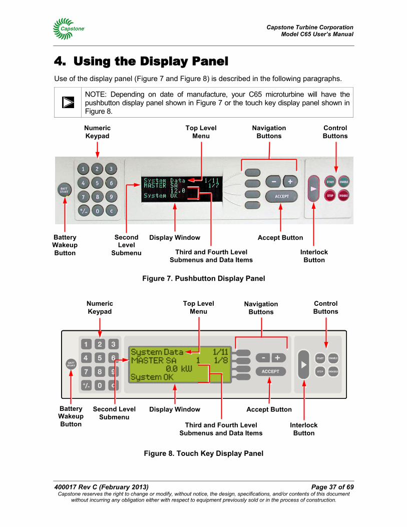
Capstone Turbine Corporation Model C65 User’s Manual
400017 Rev C (February 2013) Page 37 of 69 Capstone reserves the right to change or modify, without notice, the design, specifications, and/or contents of this document
without incurring any obligation either with respect to equipment previously sold or in the process of construction.
4. Using the Display Panel Use of the display panel (Figure 7 and Figure 8) is described in the following paragraphs.
NOTE: Depending on date of manufacture, your C65 microturbine will have the pushbutton display panel shown in Figure 7 or the touch key display panel shown in Figure 8.
Figure 7. Pushbutton Display Panel
Figure 8. Touch Key Display Panel
Numeric Keypad
Navigation Buttons
Control Buttons
Battery Wakeup Button
Display Window
Interlock Button
Top Level Menu
Third and Fourth Level Submenus and Data Items
Accept Button Second Level Submenu
Numeric Keypad
Navigation Buttons
Control Buttons
Battery Wakeup Button
Display Window
Interlock Button
Top Level Menu
Third and Fourth Level Submenus and Data Items
Accept Button Second Level
Submenu
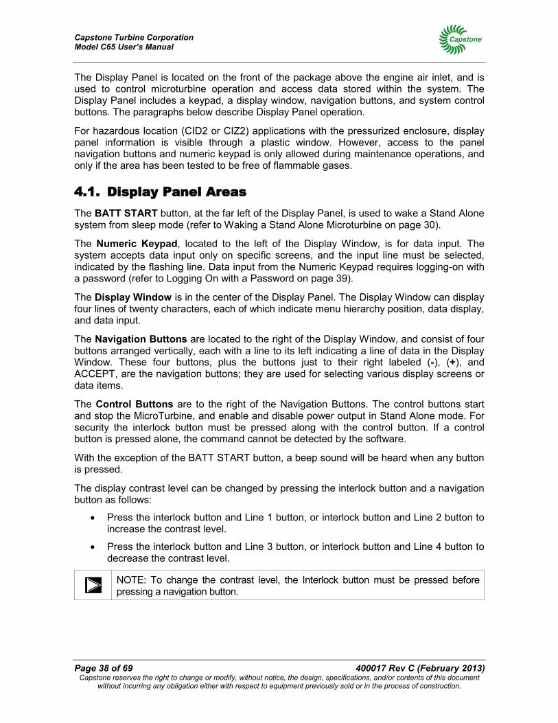
Capstone Turbine Corporation Model C65 User’s Manual
Page 38 of 69 400017 Rev C (February 2013) Capstone reserves the right to change or modify, without notice, the design, specifications, and/or contents of this document
without incurring any obligation either with respect to equipment previously sold or in the process of construction.
The Display Panel is located on the front of the package above the engine air inlet, and is used to control microturbine operation and access data stored within the system. The Display Panel includes a keypad, a display window, navigation buttons, and system control buttons. The paragraphs below describe Display Panel operation.
For hazardous location (CID2 or CIZ2) applications with the pressurized enclosure, display panel information is visible through a plastic window. However, access to the panel navigation buttons and numeric keypad is only allowed during maintenance operations, and only if the area has been tested to be free of flammable gases.
4.1. Display Panel Areas The BATT START button, at the far left of the Display Panel, is used to wake a Stand Alone system from sleep mode (refer to Waking a Stand Alone Microturbine on page 30).
The Numeric Keypad, located to the left of the Display Window, is for data input. The system accepts data input only on specific screens, and the input line must be selected, indicated by the flashing line. Data input from the Numeric Keypad requires logging-on with a password (refer to Logging On with a Password on page 39).
The Display Window is in the center of the Display Panel. The Display Window can display four lines of twenty characters, each of which indicate menu hierarchy position, data display, and data input.
The Navigation Buttons are located to the right of the Display Window, and consist of four buttons arranged vertically, each with a line to its left indicating a line of data in the Display Window. These four buttons, plus the buttons just to their right labeled (-), (+), and ACCEPT, are the navigation buttons; they are used for selecting various display screens or data items.
The Control Buttons are to the right of the Navigation Buttons. The control buttons start and stop the MicroTurbine, and enable and disable power output in Stand Alone mode. For security the interlock button must be pressed along with the control button. If a control button is pressed alone, the command cannot be detected by the software.
With the exception of the BATT START button, a beep sound will be heard when any button is pressed.
The display contrast level can be changed by pressing the interlock button and a navigation button as follows:
• Press the interlock button and Line 1 button, or interlock button and Line 2 button to increase the contrast level.
• Press the interlock button and Line 3 button, or interlock button and Line 4 button to decrease the contrast level.
NOTE: To change the contrast level, the Interlock button must be pressed before pressing a navigation button.
Capstone Turbine Corporation Model C65 User’s Manual
400017 Rev C (February 2013) Page 39 of 69 Capstone reserves the right to change or modify, without notice, the design, specifications, and/or contents of this document
without incurring any obligation either with respect to equipment previously sold or in the process of construction.
4.2. Menu Navigation Movement around the top-level menu screens can be accomplished by use of the Navigation Buttons (Figure 7 and Figure 8). The top line of the display always shows the name of the current top-level menu. To move around the top-level menus, press the topmost of the four navigation buttons. The menu position indicator numbers at the right end of the top line will flash. When the numbers are flashing, press the (-) or (+) buttons to move around the menus.
Each of the top-level menu screens has a number of submenus. The second line in the display window shows the current submenu. Movement around the submenus is similar to the top-level menus except you must press the second-line navigation button to select line two of the display. When the numbers are flashing, press the (-) or (+) buttons to move around the submenus. When you reach the desired menu, press the ACCEPT button to choose the menu, or wait 20 seconds for the system to automatically accept the menu selected.
The third and fourth levels display the selected performance data or allow input, like passwords or adjustment of power settings. The descriptions of each screen or submenu are grouped according to the top-level menu.
4.3. Display Panel Data Entry Data input requires selection of the appropriate level with the Navigation Buttons, causing the display line to flash. Enter data using the Numeric Keypad, or scroll through available data entry options with the (-) or (+) buttons and press the ACCEPT button when finished. To make changes to any system set-up or operational mode requires the entry of a user password. Numeric entries can be cancelled by use of the (-) button.
4.3.1. Logging On with a Password
To enter commands from some of the Display Panel menus, the user must log on with a valid password (the description of the various menus on the following pages includes whether logging on with a password is required).
NOTE: The default user password (at the Display Panel) is set to 87712370. In the event of a lost user password, your Capstone Authorized Service Provider can reset the user password to this default. Not all data items can be modified at the user password level.
To log on with a password, follow these steps:
1. At the top-level System Data Menu, push the second level Navigation Button and the (-) or (+) buttons until you come to the Enter Password submenu.
2. Select the third level Navigation Button (the display indicates "********"). Enter the current password (see the above notes).
3. Note that the display of ******** becomes -------- as you enter the password.
4. Press the ACCEPT Button. The display will indicate "PROTECTED LEVEL SET".
5. You are now logged into the system.

Capstone Turbine Corporation Model C65 User’s Manual
Page 40 of 69 400017 Rev C (February 2013) Capstone reserves the right to change or modify, without notice, the design, specifications, and/or contents of this document
without incurring any obligation either with respect to equipment previously sold or in the process of construction.
4.4. Display Panel Menus – Overview The Display Panel menu hierarchy shown in Figure 9 represents the typical structure of the system software menus and submenus for the Model C65 microturbine with software version 5.XX. These menus and submenus are also detailed in text following the menu hierarchy chart.
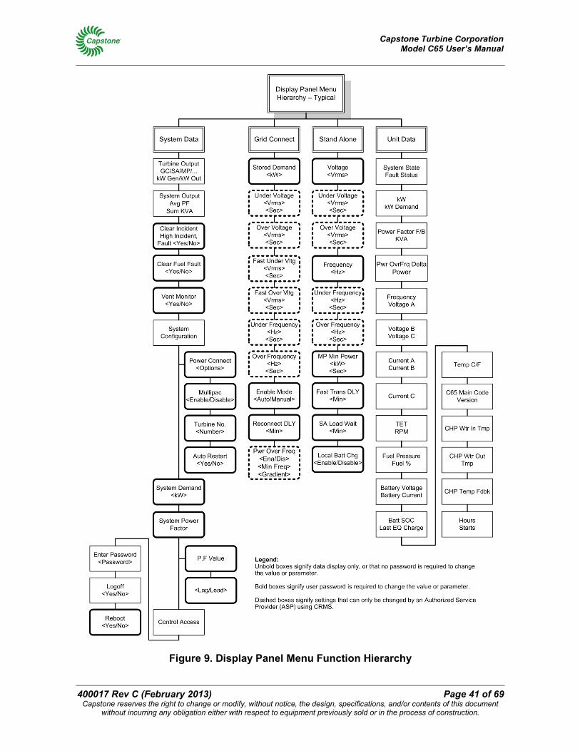
Capstone Turbine Corporation Model C65 User’s Manual
400017 Rev C (February 2013) Page 41 of 69 Capstone reserves the right to change or modify, without notice, the design, specifications, and/or contents of this document
without incurring any obligation either with respect to equipment previously sold or in the process of construction.
Figure 9. Display Panel Menu Function Hierarchy
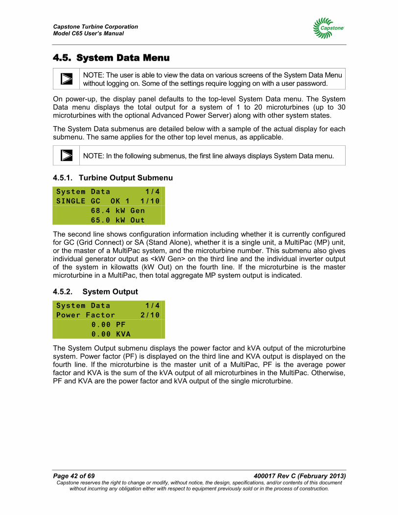
Capstone Turbine Corporation Model C65 User’s Manual
Page 42 of 69 400017 Rev C (February 2013) Capstone reserves the right to change or modify, without notice, the design, specifications, and/or contents of this document
without incurring any obligation either with respect to equipment previously sold or in the process of construction.
4.5. System Data Menu
NOTE: The user is able to view the data on various screens of the System Data Menu without logging on. Some of the settings require logging on with a user password.
On power-up, the display panel defaults to the top-level System Data menu. The System Data menu displays the total output for a system of 1 to 20 microturbines (up to 30 microturbines with the optional Advanced Power Server) along with other system states.
The System Data submenus are detailed below with a sample of the actual display for each submenu. The same applies for the other top level menus, as applicable.
NOTE: In the following submenus, the first line always displays System Data menu.
4.5.1. Turbine Output Submenu
System Data 1/4 SINGLE GC OK 1 1/10 68.4 kW Gen 65.0 kW Out
The second line shows configuration information including whether it is currently configured for GC (Grid Connect) or SA (Stand Alone), whether it is a single unit, a MultiPac (MP) unit, or the master of a MultiPac system, and the microturbine number. This submenu also gives individual generator output as <kW Gen> on the third line and the individual inverter output of the system in kilowatts (kW Out) on the fourth line. If the microturbine is the master microturbine in a MultiPac, then total aggregate MP system output is indicated.
4.5.2. System Output
System Data 1/4 Power Factor 2/10
0.00 PF 0.00 KVA
The System Output submenu displays the power factor and kVA output of the microturbine system. Power factor (PF) is displayed on the third line and KVA output is displayed on the fourth line. If the microturbine is the master unit of a MultiPac, PF is the average power factor and KVA is the sum of the kVA output of all microturbines in the MultiPac. Otherwise, PF and KVA are the power factor and kVA output of the single microturbine.
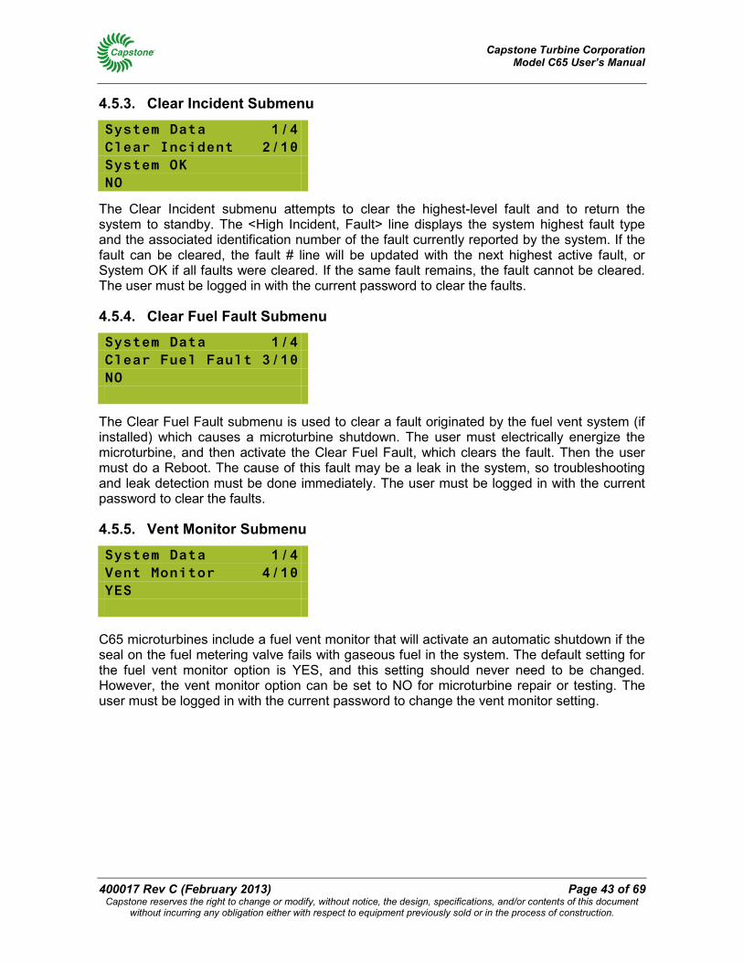
Capstone Turbine Corporation Model C65 User’s Manual
400017 Rev C (February 2013) Page 43 of 69 Capstone reserves the right to change or modify, without notice, the design, specifications, and/or contents of this document
without incurring any obligation either with respect to equipment previously sold or in the process of construction.
4.5.3. Clear Incident Submenu
System Data 1/4 Clear Incident 2/10 System OK NO
The Clear Incident submenu attempts to clear the highest-level fault and to return the system to standby. The <High Incident, Fault> line displays the system highest fault type and the associated identification number of the fault currently reported by the system. If the fault can be cleared, the fault # line will be updated with the next highest active fault, or System OK if all faults were cleared. If the same fault remains, the fault cannot be cleared. The user must be logged in with the current password to clear the faults.
4.5.4. Clear Fuel Fault Submenu
System Data 1/4 Clear Fuel Fault 3/10 NO
The Clear Fuel Fault submenu is used to clear a fault originated by the fuel vent system (if installed) which causes a microturbine shutdown. The user must electrically energize the microturbine, and then activate the Clear Fuel Fault, which clears the fault. Then the user must do a Reboot. The cause of this fault may be a leak in the system, so troubleshooting and leak detection must be done immediately. The user must be logged in with the current password to clear the faults.
4.5.5. Vent Monitor Submenu
System Data 1/4 Vent Monitor 4/10 YES
C65 microturbines include a fuel vent monitor that will activate an automatic shutdown if the seal on the fuel metering valve fails with gaseous fuel in the system. The default setting for the fuel vent monitor option is YES, and this setting should never need to be changed. However, the vent monitor option can be set to NO for microturbine repair or testing. The user must be logged in with the current password to change the vent monitor setting.
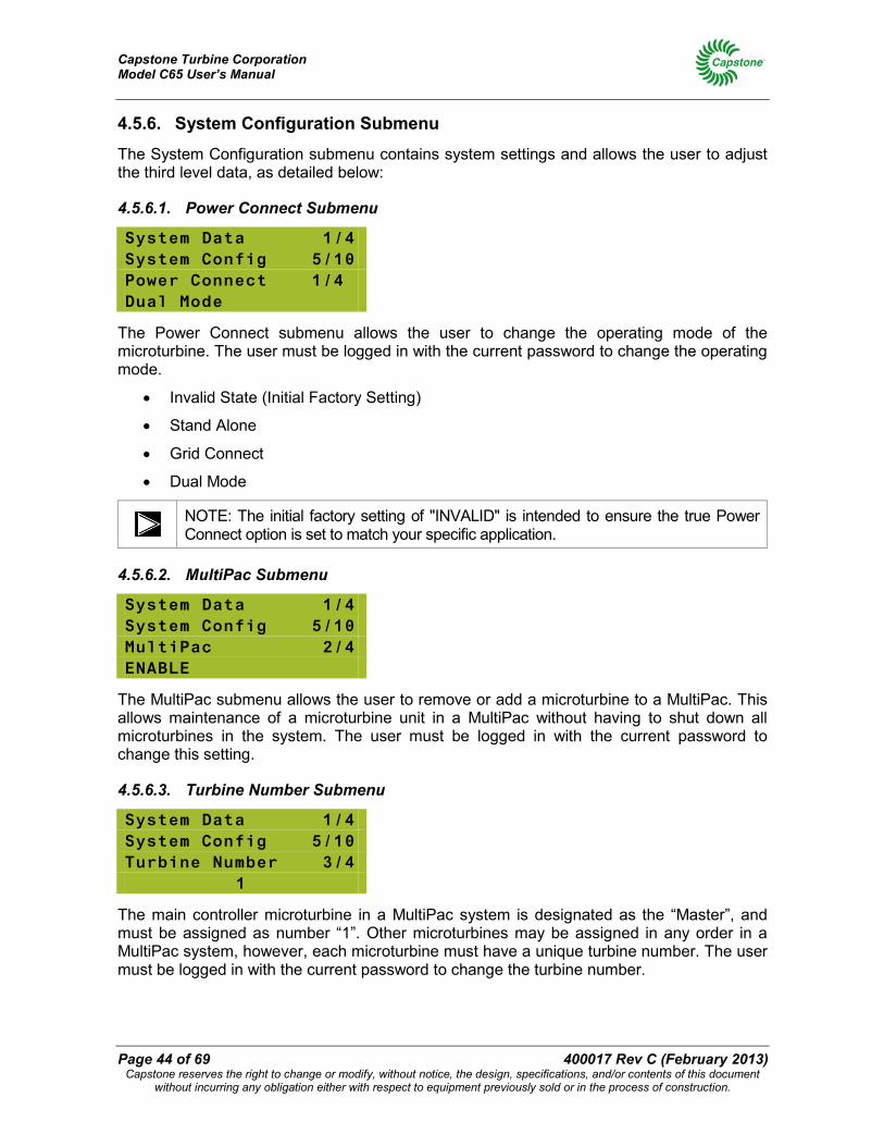
Capstone Turbine Corporation Model C65 User’s Manual
Page 44 of 69 400017 Rev C (February 2013) Capstone reserves the right to change or modify, without notice, the design, specifications, and/or contents of this document
without incurring any obligation either with respect to equipment previously sold or in the process of construction.
4.5.6. System Configuration Submenu
The System Configuration submenu contains system settings and allows the user to adjust the third level data, as detailed below:
4.5.6.1. Power Connect Submenu
System Data 1/4 System Config 5/10 Power Connect 1/4 Dual Mode
The Power Connect submenu allows the user to change the operating mode of the microturbine. The user must be logged in with the current password to change the operating mode.
• Invalid State (Initial Factory Setting)
• Stand Alone
• Grid Connect
• Dual Mode
NOTE: The initial factory setting of "INVALID" is intended to ensure the true Power Connect option is set to match your specific application.
4.5.6.2. MultiPac Submenu
System Data 1/4 System Config 5/10 MultiPac 2/4 ENABLE
The MultiPac submenu allows the user to remove or add a microturbine to a MultiPac. This allows maintenance of a microturbine unit in a MultiPac without having to shut down all microturbines in the system. The user must be logged in with the current password to change this setting.
4.5.6.3. Turbine Number Submenu
System Data 1/4 System Config 5/10 Turbine Number 3/4
1
The main controller microturbine in a MultiPac system is designated as the “Master”, and must be assigned as number “1”. Other microturbines may be assigned in any order in a MultiPac system, however, each microturbine must have a unique turbine number. The user must be logged in with the current password to change the turbine number.
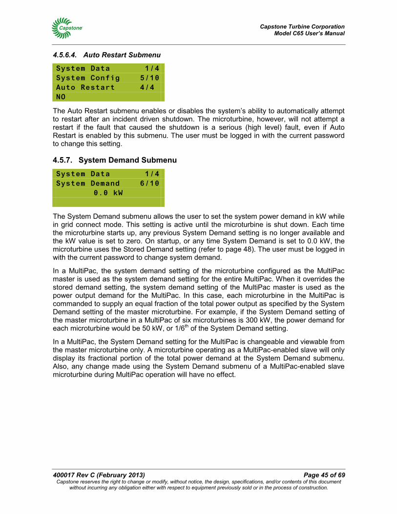
Capstone Turbine Corporation Model C65 User’s Manual
400017 Rev C (February 2013) Page 45 of 69 Capstone reserves the right to change or modify, without notice, the design, specifications, and/or contents of this document
without incurring any obligation either with respect to equipment previously sold or in the process of construction.
4.5.6.4. Auto Restart Submenu
System Data 1/4 System Config 5/10 Auto Restart 4/4 NO
The Auto Restart submenu enables or disables the system’s ability to automatically attempt to restart after an incident driven shutdown. The microturbine, however, will not attempt a restart if the fault that caused the shutdown is a serious (high level) fault, even if Auto Restart is enabled by this submenu. The user must be logged in with the current password to change this setting.
4.5.7. System Demand Submenu
System Data 1/4 System Demand 6/10
0.0 kW
The System Demand submenu allows the user to set the system power demand in kW while in grid connect mode. This setting is active until the microturbine is shut down. Each time the microturbine starts up, any previous System Demand setting is no longer available and the kW value is set to zero. On startup, or any time System Demand is set to 0.0 kW, the microturbine uses the Stored Demand setting (refer to page 48). The user must be logged in with the current password to change system demand.
In a MultiPac, the system demand setting of the microturbine configured as the MultiPac master is used as the system demand setting for the entire MultiPac. When it overrides the stored demand setting, the system demand setting of the MultiPac master is used as the power output demand for the MultiPac. In this case, each microturbine in the MultiPac is commanded to supply an equal fraction of the total power output as specified by the System Demand setting of the master microturbine. For example, if the System Demand setting of the master microturbine in a MultiPac of six microturbines is 300 kW, the power demand for each microturbine would be 50 kW, or 1/6th of the System Demand setting.
In a MultiPac, the System Demand setting for the MultiPac is changeable and viewable from the master microturbine only. A microturbine operating as a MultiPac-enabled slave will only display its fractional portion of the total power demand at the System Demand submenu. Also, any change made using the System Demand submenu of a MultiPac-enabled slave microturbine during MultiPac operation will have no effect.
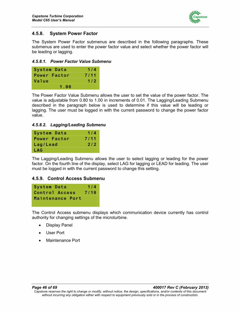
Capstone Turbine Corporation Model C65 User’s Manual
Page 46 of 69 400017 Rev C (February 2013) Capstone reserves the right to change or modify, without notice, the design, specifications, and/or contents of this document
without incurring any obligation either with respect to equipment previously sold or in the process of construction.
4.5.8. System Power Factor
The System Power Factor submenus are described in the following paragraphs. These submenus are used to enter the power factor value and select whether the power factor will be leading or lagging.
4.5.8.1. Power Factor Value Submenu
System Data 1/4 Power Factor 7/11 Value 1/2
1.00
The Power Factor Value Submenu allows the user to set the value of the power factor. The value is adjustable from 0.80 to 1.00 in increments of 0.01. The Lagging/Leading Submenu described in the paragraph below is used to determine if this value will be leading or lagging. The user must be logged in with the current password to change the power factor value.
4.5.8.2. Lagging/Leading Submenu
System Data 1/4 Power Factor 7/11 Lag/Lead 2/2 LAG
The Lagging/Leading Submenu allows the user to select lagging or leading for the power factor. On the fourth line of the display, select LAG for lagging or LEAD for leading. The user must be logged in with the current password to change this setting.
4.5.9. Control Access Submenu
System Data 1/4 Control Access 7/10 Maintenance Port
The Control Access submenu displays which communication device currently has control authority for changing settings of the microturbine.
• Display Panel
• User Port
• Maintenance Port
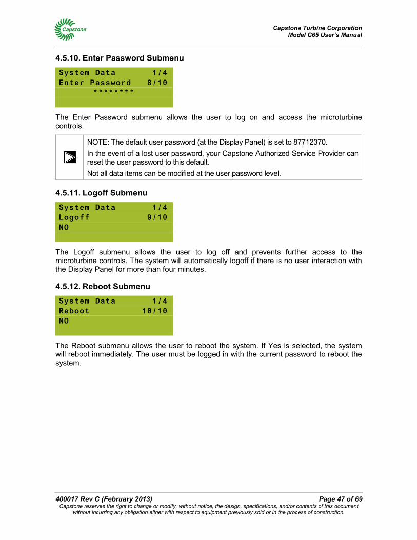
Capstone Turbine Corporation Model C65 User’s Manual
400017 Rev C (February 2013) Page 47 of 69 Capstone reserves the right to change or modify, without notice, the design, specifications, and/or contents of this document
without incurring any obligation either with respect to equipment previously sold or in the process of construction.
4.5.10. Enter Password Submenu
System Data 1/4 Enter Password 8/10
********
The Enter Password submenu allows the user to log on and access the microturbine controls.
NOTE: The default user password (at the Display Panel) is set to 87712370. In the event of a lost user password, your Capstone Authorized Service Provider can reset the user password to this default. Not all data items can be modified at the user password level.
4.5.11. Logoff Submenu
System Data 1/4 Logoff 9/10 NO
The Logoff submenu allows the user to log off and prevents further access to the microturbine controls. The system will automatically logoff if there is no user interaction with the Display Panel for more than four minutes.
4.5.12. Reboot Submenu
System Data 1/4 Reboot 10/10 NO
The Reboot submenu allows the user to reboot the system. If Yes is selected, the system will reboot immediately. The user must be logged in with the current password to reboot the system.
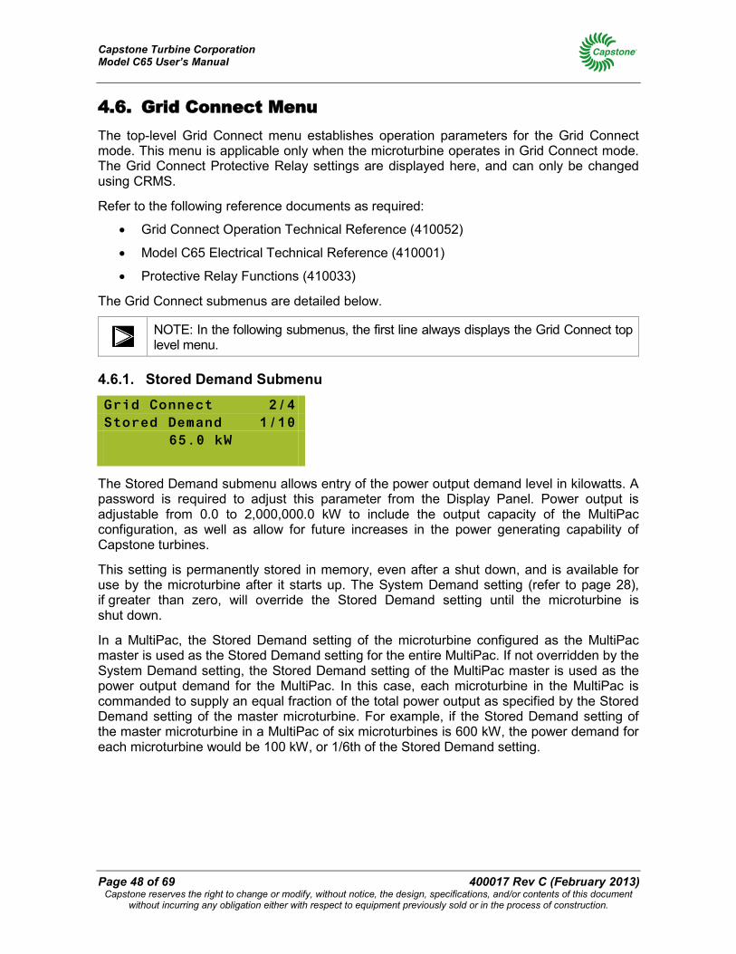
Capstone Turbine Corporation Model C65 User’s Manual
Page 48 of 69 400017 Rev C (February 2013) Capstone reserves the right to change or modify, without notice, the design, specifications, and/or contents of this document
without incurring any obligation either with respect to equipment previously sold or in the process of construction.
4.6. Grid Connect Menu The top-level Grid Connect menu establishes operation parameters for the Grid Connect mode. This menu is applicable only when the microturbine operates in Grid Connect mode. The Grid Connect Protective Relay settings are displayed here, and can only be changed using CRMS.
Refer to the following reference documents as required:
• Grid Connect Operation Technical Reference (410052)
• Model C65 Electrical Technical Reference (410001)
• Protective Relay Functions (410033)
The Grid Connect submenus are detailed below.
NOTE: In the following submenus, the first line always displays the Grid Connect top level menu.
4.6.1. Stored Demand Submenu
Grid Connect 2/4 Stored Demand 1/10
65.0 kW
The Stored Demand submenu allows entry of the power output demand level in kilowatts. A password is required to adjust this parameter from the Display Panel. Power output is adjustable from 0.0 to 2,000,000.0 kW to include the output capacity of the MultiPac configuration, as well as allow for future increases in the power generating capability of Capstone turbines.
This setting is permanently stored in memory, even after a shut down, and is available for use by the microturbine after it starts up. The System Demand setting (refer to page 28), if greater than zero, will override the Stored Demand setting until the microturbine is shut down.
In a MultiPac, the Stored Demand setting of the microturbine configured as the MultiPac master is used as the Stored Demand setting for the entire MultiPac. If not overridden by the System Demand setting, the Stored Demand setting of the MultiPac master is used as the power output demand for the MultiPac. In this case, each microturbine in the MultiPac is commanded to supply an equal fraction of the total power output as specified by the Stored Demand setting of the master microturbine. For example, if the Stored Demand setting of the master microturbine in a MultiPac of six microturbines is 600 kW, the power demand for each microturbine would be 100 kW, or 1/6th of the Stored Demand setting.
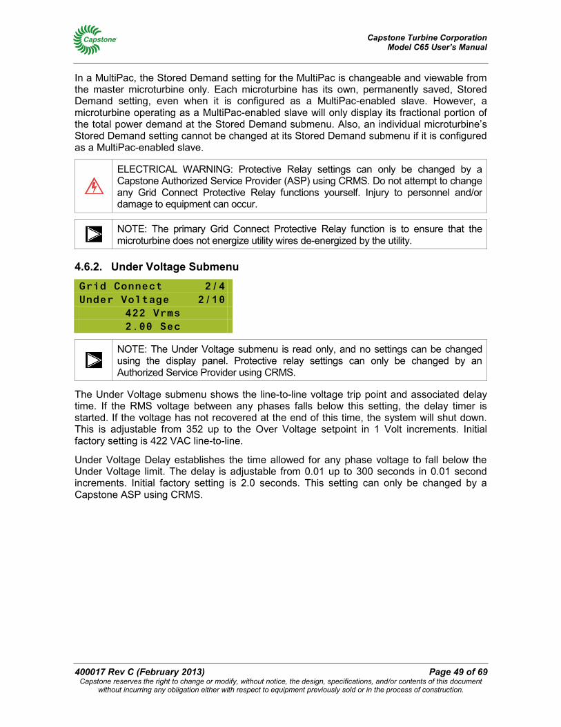
Capstone Turbine Corporation Model C65 User’s Manual
400017 Rev C (February 2013) Page 49 of 69 Capstone reserves the right to change or modify, without notice, the design, specifications, and/or contents of this document
without incurring any obligation either with respect to equipment previously sold or in the process of construction.
In a MultiPac, the Stored Demand setting for the MultiPac is changeable and viewable from the master microturbine only. Each microturbine has its own, permanently saved, Stored Demand setting, even when it is configured as a MultiPac-enabled slave. However, a microturbine operating as a MultiPac-enabled slave will only display its fractional portion of the total power demand at the Stored Demand submenu. Also, an individual microturbine’s Stored Demand setting cannot be changed at its Stored Demand submenu if it is configured as a MultiPac-enabled slave.
ELECTRICAL WARNING: Protective Relay settings can only be changed by a Capstone Authorized Service Provider (ASP) using CRMS. Do not attempt to change any Grid Connect Protective Relay functions yourself. Injury to personnel and/or damage to equipment can occur.
NOTE: The primary Grid Connect Protective Relay function is to ensure that the microturbine does not energize utility wires de-energized by the utility.
4.6.2. Under Voltage Submenu
Grid Connect 2/4 Under Voltage 2/10
422 Vrms 2.00 Sec
NOTE: The Under Voltage submenu is read only, and no settings can be changed using the display panel. Protective relay settings can only be changed by an Authorized Service Provider using CRMS.
The Under Voltage submenu shows the line-to-line voltage trip point and associated delay time. If the RMS voltage between any phases falls below this setting, the delay timer is started. If the voltage has not recovered at the end of this time, the system will shut down. This is adjustable from 352 up to the Over Voltage setpoint in 1 Volt increments. Initial factory setting is 422 VAC line-to-line.
Under Voltage Delay establishes the time allowed for any phase voltage to fall below the Under Voltage limit. The delay is adjustable from 0.01 up to 300 seconds in 0.01 second increments. Initial factory setting is 2.0 seconds. This setting can only be changed by a Capstone ASP using CRMS.
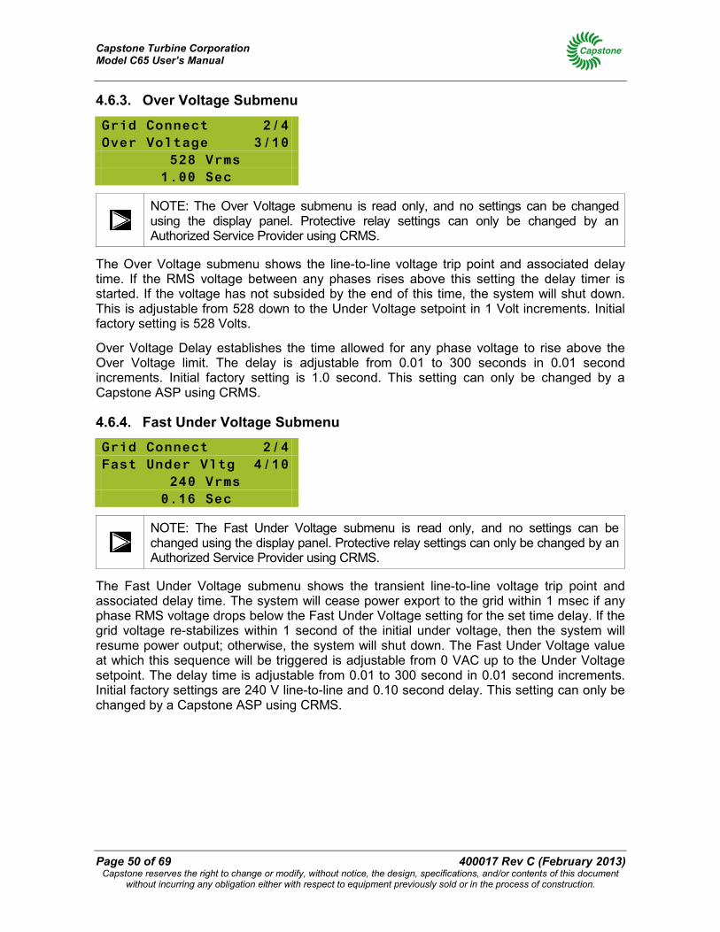
Capstone Turbine Corporation Model C65 User’s Manual
Page 50 of 69 400017 Rev C (February 2013) Capstone reserves the right to change or modify, without notice, the design, specifications, and/or contents of this document
without incurring any obligation either with respect to equipment previously sold or in the process of construction.
4.6.3. Over Voltage Submenu
Grid Connect 2/4 Over Voltage 3/10
528 Vrms 1.00 Sec
NOTE: The Over Voltage submenu is read only, and no settings can be changed using the display panel. Protective relay settings can only be changed by an Authorized Service Provider using CRMS.
The Over Voltage submenu shows the line-to-line voltage trip point and associated delay time. If the RMS voltage between any phases rises above this setting the delay timer is started. If the voltage has not subsided by the end of this time, the system will shut down. This is adjustable from 528 down to the Under Voltage setpoint in 1 Volt increments. Initial factory setting is 528 Volts.
Over Voltage Delay establishes the time allowed for any phase voltage to rise above the Over Voltage limit. The delay is adjustable from 0.01 to 300 seconds in 0.01 second increments. Initial factory setting is 1.0 second. This setting can only be changed by a Capstone ASP using CRMS.
4.6.4. Fast Under Voltage Submenu
Grid Connect 2/4 Fast Under Vltg 4/10
240 Vrms 0.16 Sec
NOTE: The Fast Under Voltage submenu is read only, and no settings can be changed using the display panel. Protective relay settings can only be changed by an Authorized Service Provider using CRMS.
The Fast Under Voltage submenu shows the transient line-to-line voltage trip point and associated delay time. The system will cease power export to the grid within 1 msec if any phase RMS voltage drops below the Fast Under Voltage setting for the set time delay. If the grid voltage re-stabilizes within 1 second of the initial under voltage, then the system will resume power output; otherwise, the system will shut down. The Fast Under Voltage value at which this sequence will be triggered is adjustable from 0 VAC up to the Under Voltage setpoint. The delay time is adjustable from 0.01 to 300 second in 0.01 second increments. Initial factory settings are 240 V line-to-line and 0.10 second delay. This setting can only be changed by a Capstone ASP using CRMS.
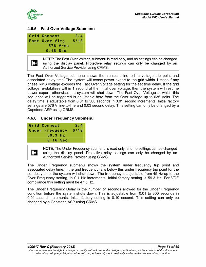
Capstone Turbine Corporation Model C65 User’s Manual
400017 Rev C (February 2013) Page 51 of 69 Capstone reserves the right to change or modify, without notice, the design, specifications, and/or contents of this document
without incurring any obligation either with respect to equipment previously sold or in the process of construction.
4.6.5. Fast Over Voltage Submenu
Grid Connect 2/4 Fast Over Vltg 5/10
576 Vrms 0.16 Sec
NOTE: The Fast Over Voltage submenu is read only, and no settings can be changed using the display panel. Protective relay settings can only be changed by an Authorized Service Provider using CRMS.
The Fast Over Voltage submenu shows the transient line-to-line voltage trip point and associated delay time. The system will cease power export to the grid within 1 msec if any phase RMS voltage exceeds the Fast Over Voltage setting for the set time delay. If the grid voltage re-stabilizes within 1 second of the initial over voltage, then the system will resume power export; otherwise, the system will shut down. The Fast Over Voltage at which this sequence will be triggered is adjustable here from the Over Voltage up to 635 Volts. The delay time is adjustable from 0.01 to 300 seconds in 0.01 second increments. Initial factory settings are 576 V line-to-line and 0.03 second delay. This setting can only be changed by a Capstone ASP using CRMS.
4.6.6. Under Frequency Submenu
Grid Connect 2/4 Under Frequency 6/10
59.3 Hz 0.16 Sec
NOTE: The Under Frequency submenu is read only, and no settings can be changed using the display panel. Protective relay settings can only be changed by an Authorized Service Provider using CRMS.
The Under Frequency submenu shows the system under frequency trip point and associated delay time. If the grid frequency falls below this under frequency trip point for the set delay time, the system will shut down. The frequency is adjustable from 45 Hz up to the Over Frequency setting, in 0.1 Hz increments. Initial factory setting is 59.3 Hz. For VDE compliance this setting must be 47.5 Hz.
The Under Frequency Delay is the number of seconds allowed for the Under Frequency condition before the system shuts down. This is adjustable from 0.01 to 300 seconds in 0.01 second increments. Initial factory setting is 0.10 second. This setting can only be changed by a Capstone ASP using CRMS.
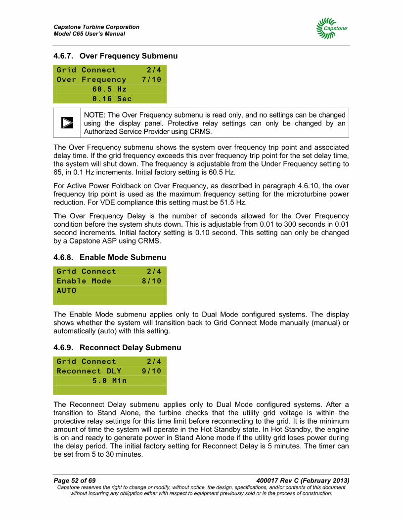
Capstone Turbine Corporation Model C65 User’s Manual
Page 52 of 69 400017 Rev C (February 2013) Capstone reserves the right to change or modify, without notice, the design, specifications, and/or contents of this document
without incurring any obligation either with respect to equipment previously sold or in the process of construction.
4.6.7. Over Frequency Submenu
Grid Connect 2/4 Over Frequency 7/10
60.5 Hz 0.16 Sec
NOTE: The Over Frequency submenu is read only, and no settings can be changed using the display panel. Protective relay settings can only be changed by an Authorized Service Provider using CRMS.
The Over Frequency submenu shows the system over frequency trip point and associated delay time. If the grid frequency exceeds this over frequency trip point for the set delay time, the system will shut down. The frequency is adjustable from the Under Frequency setting to 65, in 0.1 Hz increments. Initial factory setting is 60.5 Hz.
For Active Power Foldback on Over Frequency, as described in paragraph 4.6.10, the over frequency trip point is used as the maximum frequency setting for the microturbine power reduction. For VDE compliance this setting must be 51.5 Hz.
The Over Frequency Delay is the number of seconds allowed for the Over Frequency condition before the system shuts down. This is adjustable from 0.01 to 300 seconds in 0.01 second increments. Initial factory setting is 0.10 second. This setting can only be changed by a Capstone ASP using CRMS.
4.6.8. Enable Mode Submenu
Grid Connect 2/4 Enable Mode 8/10 AUTO
The Enable Mode submenu applies only to Dual Mode configured systems. The display shows whether the system will transition back to Grid Connect Mode manually (manual) or automatically (auto) with this setting.
4.6.9. Reconnect Delay Submenu
Grid Connect 2/4 Reconnect DLY 9/10
5.0 Min
The Reconnect Delay submenu applies only to Dual Mode configured systems. After a transition to Stand Alone, the turbine checks that the utility grid voltage is within the protective relay settings for this time limit before reconnecting to the grid. It is the minimum amount of time the system will operate in the Hot Standby state. In Hot Standby, the engine is on and ready to generate power in Stand Alone mode if the utility grid loses power during the delay period. The initial factory setting for Reconnect Delay is 5 minutes. The timer can be set from 5 to 30 minutes.
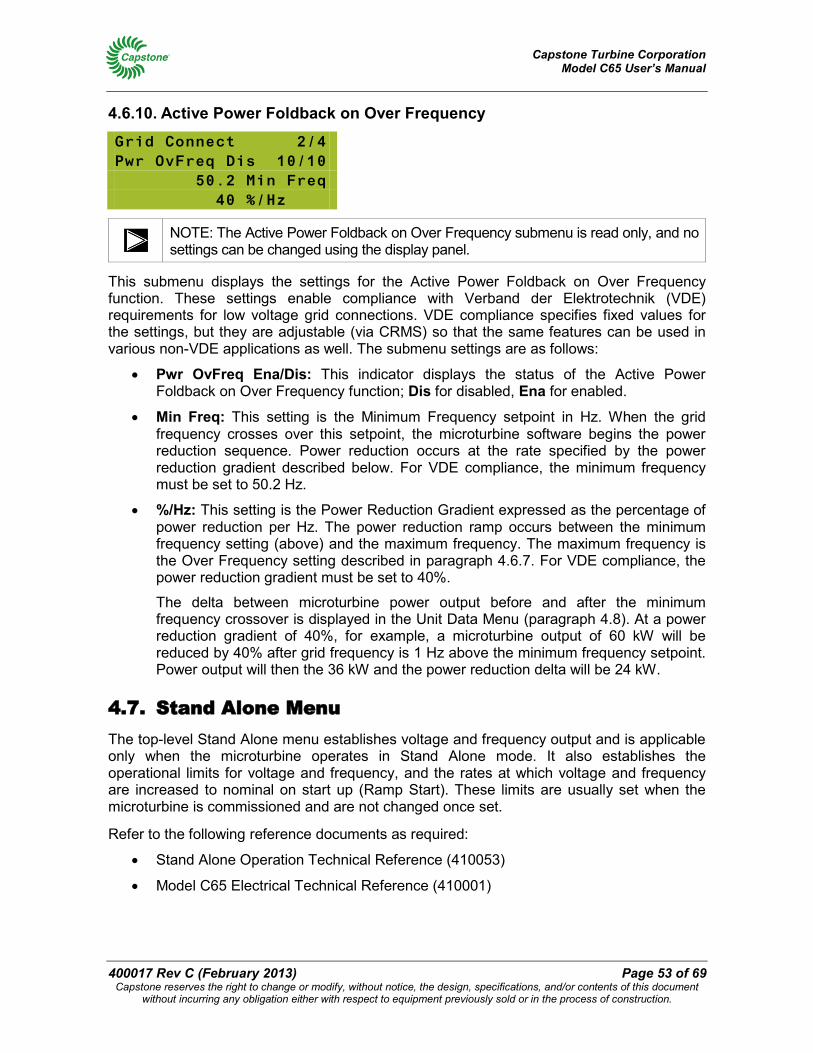
Capstone Turbine Corporation Model C65 User’s Manual
400017 Rev C (February 2013) Page 53 of 69 Capstone reserves the right to change or modify, without notice, the design, specifications, and/or contents of this document
without incurring any obligation either with respect to equipment previously sold or in the process of construction.
4.6.10. Active Power Foldback on Over Frequency
Grid Connect 2/4 Pwr OvFreq Dis 10/10 50.2 Min Freq 40 %/Hz
NOTE: The Active Power Foldback on Over Frequency submenu is read only, and no settings can be changed using the display panel.
This submenu displays the settings for the Active Power Foldback on Over Frequency function. These settings enable compliance with Verband der Elektrotechnik (VDE) requirements for low voltage grid connections. VDE compliance specifies fixed values for the settings, but they are adjustable (via CRMS) so that the same features can be used in various non-VDE applications as well. The submenu settings are as follows:
• Pwr OvFreq Ena/Dis: This indicator displays the status of the Active Power Foldback on Over Frequency function; Dis for disabled, Ena for enabled.
• Min Freq: This setting is the Minimum Frequency setpoint in Hz. When the grid frequency crosses over this setpoint, the microturbine software begins the power reduction sequence. Power reduction occurs at the rate specified by the power reduction gradient described below. For VDE compliance, the minimum frequency must be set to 50.2 Hz.
• %/Hz: This setting is the Power Reduction Gradient expressed as the percentage of power reduction per Hz. The power reduction ramp occurs between the minimum frequency setting (above) and the maximum frequency. The maximum frequency is the Over Frequency setting described in paragraph 4.6.7. For VDE compliance, the power reduction gradient must be set to 40%.
The delta between microturbine power output before and after the minimum frequency crossover is displayed in the Unit Data Menu (paragraph 4.8). At a power reduction gradient of 40%, for example, a microturbine output of 60 kW will be reduced by 40% after grid frequency is 1 Hz above the minimum frequency setpoint. Power output will then the 36 kW and the power reduction delta will be 24 kW.
4.7. Stand Alone Menu The top-level Stand Alone menu establishes voltage and frequency output and is applicable only when the microturbine operates in Stand Alone mode. It also establishes the operational limits for voltage and frequency, and the rates at which voltage and frequency are increased to nominal on start up (Ramp Start). These limits are usually set when the microturbine is commissioned and are not changed once set.
Refer to the following reference documents as required:
• Stand Alone Operation Technical Reference (410053)
• Model C65 Electrical Technical Reference (410001)
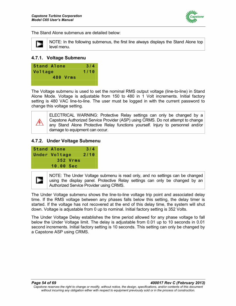
Capstone Turbine Corporation Model C65 User’s Manual
Page 54 of 69 400017 Rev C (February 2013) Capstone reserves the right to change or modify, without notice, the design, specifications, and/or contents of this document
without incurring any obligation either with respect to equipment previously sold or in the process of construction.
The Stand Alone submenus are detailed below:
NOTE: In the following submenus, the first line always displays the Stand Alone top level menu.
4.7.1. Voltage Submenu
Stand Alone 3/4 Voltage 1/10
480 Vrms
The Voltage submenu is used to set the nominal RMS output voltage (line-to-line) in Stand Alone Mode. Voltage is adjustable from 150 to 480 in 1 Volt increments. Initial factory setting is 480 VAC line-to-line. The user must be logged in with the current password to change this voltage setting.
ELECTRICAL WARNING: Protective Relay settings can only be changed by a Capstone Authorized Service Provider (ASP) using CRMS. Do not attempt to change any Stand Alone Protective Relay functions yourself. Injury to personnel and/or damage to equipment can occur.
4.7.2. Under Voltage Submenu
Stand Alone 3/4 Under Voltage 2/10
352 Vrms 10.00 Sec
NOTE: The Under Voltage submenu is read only, and no settings can be changed using the display panel. Protective Relay settings can only be changed by an Authorized Service Provider using CRMS.
The Under Voltage submenu shows the line-to-line voltage trip point and associated delay time. If the RMS voltage between any phases falls below this setting, the delay timer is started. If the voltage has not recovered at the end of this delay time, the system will shut down. Voltage is adjustable from 0 up to nominal. Initial factory setting is 352 Volts.
The Under Voltage Delay establishes the time period allowed for any phase voltage to fall below the Under Voltage limit. The delay is adjustable from 0.01 up to 10 seconds in 0.01 second increments. Initial factory setting is 10 seconds. This setting can only be changed by a Capstone ASP using CRMS.
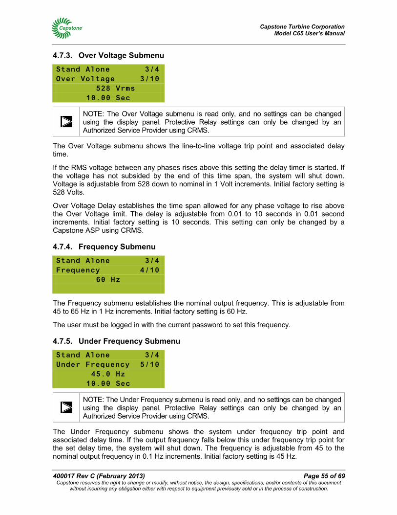
Capstone Turbine Corporation Model C65 User’s Manual
400017 Rev C (February 2013) Page 55 of 69 Capstone reserves the right to change or modify, without notice, the design, specifications, and/or contents of this document
without incurring any obligation either with respect to equipment previously sold or in the process of construction.
4.7.3. Over Voltage Submenu
Stand Alone 3/4 Over Voltage 3/10
528 Vrms 10.00 Sec
NOTE: The Over Voltage submenu is read only, and no settings can be changed using the display panel. Protective Relay settings can only be changed by an Authorized Service Provider using CRMS.
The Over Voltage submenu shows the line-to-line voltage trip point and associated delay time.
If the RMS voltage between any phases rises above this setting the delay timer is started. If the voltage has not subsided by the end of this time span, the system will shut down. Voltage is adjustable from 528 down to nominal in 1 Volt increments. Initial factory setting is 528 Volts.
Over Voltage Delay establishes the time span allowed for any phase voltage to rise above the Over Voltage limit. The delay is adjustable from 0.01 to 10 seconds in 0.01 second increments. Initial factory setting is 10 seconds. This setting can only be changed by a Capstone ASP using CRMS.
4.7.4. Frequency Submenu
Stand Alone 3/4 Frequency 4/10
60 Hz
The Frequency submenu establishes the nominal output frequency. This is adjustable from 45 to 65 Hz in 1 Hz increments. Initial factory setting is 60 Hz.
The user must be logged in with the current password to set this frequency.
4.7.5. Under Frequency Submenu
Stand Alone 3/4 Under Frequency 5/10
45.0 Hz 10.00 Sec
NOTE: The Under Frequency submenu is read only, and no settings can be changed using the display panel. Protective Relay settings can only be changed by an Authorized Service Provider using CRMS.
The Under Frequency submenu shows the system under frequency trip point and associated delay time. If the output frequency falls below this under frequency trip point for the set delay time, the system will shut down. The frequency is adjustable from 45 to the nominal output frequency in 0.1 Hz increments. Initial factory setting is 45 Hz.
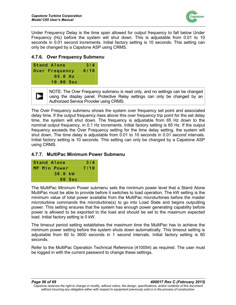
Capstone Turbine Corporation Model C65 User’s Manual
Page 56 of 69 400017 Rev C (February 2013) Capstone reserves the right to change or modify, without notice, the design, specifications, and/or contents of this document
without incurring any obligation either with respect to equipment previously sold or in the process of construction.
Under Frequency Delay is the time span allowed for output frequency to fall below Under Frequency (Hz) before the system will shut down. This is adjustable from 0.01 to 10 seconds in 0.01 second increments. Initial factory setting is 10 seconds. This setting can only be changed by a Capstone ASP using CRMS.
4.7.6. Over Frequency Submenu
Stand Alone 3/4 Over Frequency 6/10
65.0 Hz 10.00 Sec
NOTE: The Over Frequency submenu is read only, and no settings can be changed using the display panel. Protective Relay settings can only be changed by an Authorized Service Provider using CRMS.
The Over Frequency submenu shows the system over frequency set point and associated delay time. If the output frequency rises above this over frequency trip point for the set delay time, the system will shut down. The frequency is adjustable from 65 Hz down to the nominal output frequency, in 0.1 Hz increments. Initial factory setting is 65 Hz. If the output frequency exceeds the Over Frequency setting for the time delay setting, the system will shut down. The time delay is adjustable from 0.01 to 10 seconds in 0.01 second intervals. Initial factory setting is 10 seconds. This setting can only be changed by a Capstone ASP using CRMS.
4.7.7. MultiPac Minimum Power Submenu
Stand Alone 3/4 MP Min Power 7/10
30.0 kW 60 Sec
The MultiPac Minimum Power submenu sets the minimum power level that a Stand Alone MultiPac must be able to provide before it switches to load operation. The kW setting is the minimum value of total power available from the MultiPac microturbines before the master microturbine commands the microturbine(s) to go into Load State and begins outputting power. This setting ensures that the system has enough power generating capability before power is allowed to be exported to the load and should be set to the maximum expected load. Initial factory setting is 0 kW.
The timeout period setting establishes the maximum time the MultiPac has to achieve the minimum power setting before the system shuts down automatically. This timeout setting is adjustable from 60 to 3600 seconds in 1 second intervals. Initial factory setting is 60 seconds.
Refer to the MultiPac Operation Technical Reference (410054) as required. The user must be logged in with the current password to change these settings.
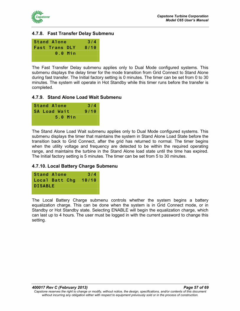
Capstone Turbine Corporation Model C65 User’s Manual
400017 Rev C (February 2013) Page 57 of 69 Capstone reserves the right to change or modify, without notice, the design, specifications, and/or contents of this document
without incurring any obligation either with respect to equipment previously sold or in the process of construction.
4.7.8. Fast Transfer Delay Submenu
Stand Alone 3/4 Fast Trans DLY 8/10
0.0 Min
The Fast Transfer Delay submenu applies only to Dual Mode configured systems. This submenu displays the delay timer for the mode transition from Grid Connect to Stand Alone during fast transfer. The Initial factory setting is 0 minutes. The timer can be set from 0 to 30 minutes. The system will operate in Hot Standby while this timer runs before the transfer is completed.
4.7.9. Stand Alone Load Wait Submenu
Stand Alone 3/4 SA Load Wait 9/10
5.0 Min
The Stand Alone Load Wait submenu applies only to Dual Mode configured systems. This submenu displays the timer that maintains the system in Stand Alone Load State before the transition back to Grid Connect, after the grid has returned to normal. The timer begins when the utility voltage and frequency are detected to be within the required operating range, and maintains the turbine in the Stand Alone load state until the time has expired. The Initial factory setting is 5 minutes. The timer can be set from 5 to 30 minutes.
4.7.10. Local Battery Charge Submenu
Stand Alone 3/4 Local Batt Chg 10/10 DISABLE
The Local Battery Charge submenu controls whether the system begins a battery equalization charge. This can be done when the system is in Grid Connect mode, or in Standby or Hot Standby state. Selecting ENABLE will begin the equalization charge, which can last up to 4 hours. The user must be logged in with the current password to change this setting.
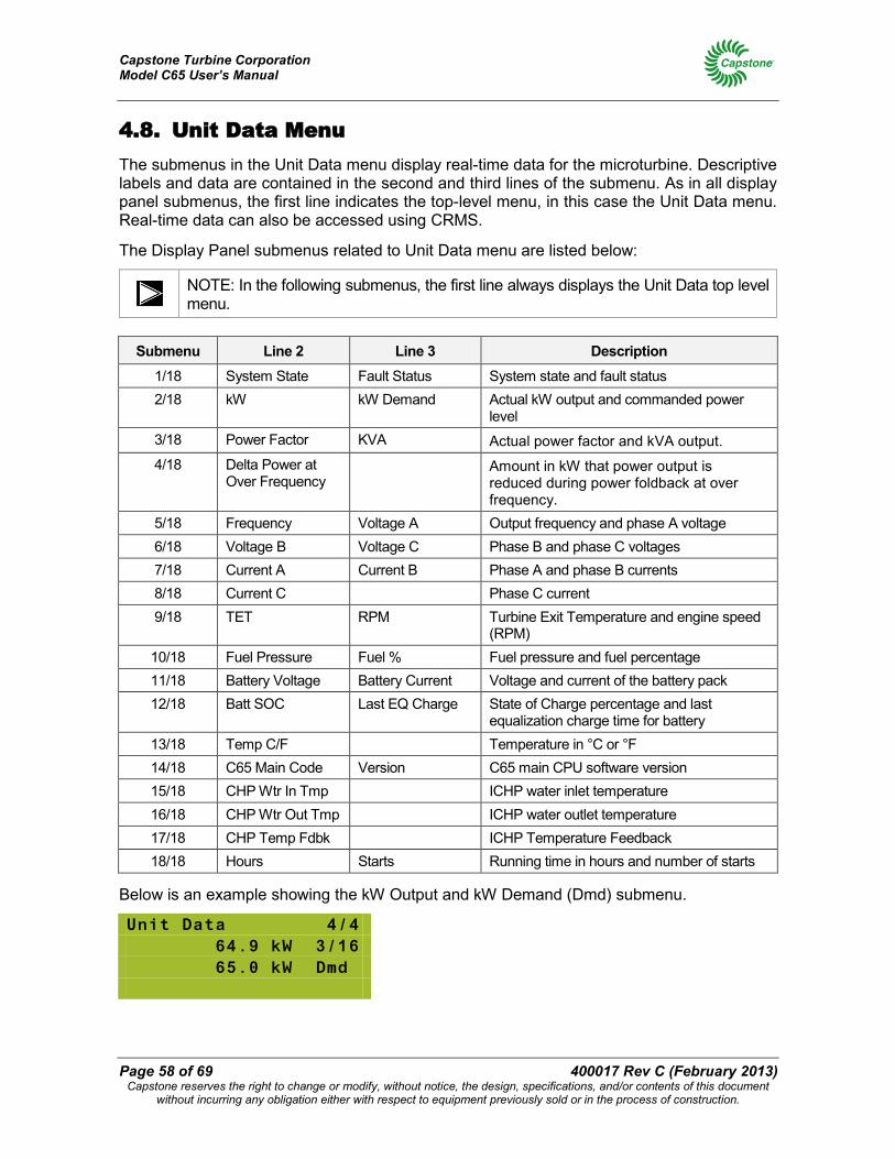
Capstone Turbine Corporation Model C65 User’s Manual
Page 58 of 69 400017 Rev C (February 2013) Capstone reserves the right to change or modify, without notice, the design, specifications, and/or contents of this document
without incurring any obligation either with respect to equipment previously sold or in the process of construction.
4.8. Unit Data Menu The submenus in the Unit Data menu display real-time data for the microturbine. Descriptive labels and data are contained in the second and third lines of the submenu. As in all display panel submenus, the first line indicates the top-level menu, in this case the Unit Data menu. Real-time data can also be accessed using CRMS.
The Display Panel submenus related to Unit Data menu are listed below:
NOTE: In the following submenus, the first line always displays the Unit Data top level menu.
Submenu Line 2 Line 3 Description
1/18 System State Fault Status System state and fault status 2/18 kW kW Demand Actual kW output and commanded power
level 3/18 Power Factor KVA Actual power factor and kVA output. 4/18 Delta Power at
Over Frequency Amount in kW that power output is
reduced during power foldback at over frequency.
5/18 Frequency Voltage A Output frequency and phase A voltage 6/18 Voltage B Voltage C Phase B and phase C voltages 7/18 Current A Current B Phase A and phase B currents 8/18 Current C Phase C current 9/18 TET RPM Turbine Exit Temperature and engine speed
(RPM) 10/18 Fuel Pressure Fuel % Fuel pressure and fuel percentage 11/18 Battery Voltage Battery Current Voltage and current of the battery pack 12/18 Batt SOC Last EQ Charge State of Charge percentage and last
equalization charge time for battery 13/18 Temp C/F Temperature in °C or °F 14/18 C65 Main Code Version C65 main CPU software version 15/18 CHP Wtr In Tmp ICHP water inlet temperature 16/18 CHP Wtr Out Tmp ICHP water outlet temperature 17/18 CHP Temp Fdbk ICHP Temperature Feedback 18/18 Hours Starts Running time in hours and number of starts
Below is an example showing the kW Output and kW Demand (Dmd) submenu.
Unit Data 4/4 64.9 kW 3/16 65.0 kW Dmd
Capstone Turbine Corporation Model C65 User’s Manual
400017 Rev C (February 2013) Page 59 of 69 Capstone reserves the right to change or modify, without notice, the design, specifications, and/or contents of this document
without incurring any obligation either with respect to equipment previously sold or in the process of construction.
5. Microturbine Preventive Maintenance This section details the preventive maintenance procedures that must be performed on the Capstone Microturbine.
ELECTRICAL WARNING: The microturbine system generates and uses voltage levels that can injure or kill. Obey all safety precautions when you work with or around electrical equipment.
NOTE: Failure to provide proper maintenance will void the microturbine warranty. Users do not perform the following microturbine maintenance procedures, but it is important for users to be aware of them.
Only Capstone Authorized Service Providers can access the inside of the microturbine enclosure (except for accessing the User Connection Board in the UCB/JUCB).
Only Capstone Authorized Service Providers can perform maintenance on the microturbine components.
5.1. Scheduled Maintenance Preventive maintenance of the C65 microturbine includes performing scheduled maintenance of its components at regular intervals. The list of maintenance schedules for C65 components is contained in the Microturbine Standard Maintenance Schedule Work Instructions (440000). This document is available from your Authorized Service Provider for reference. Only Authorized Service Providers are permitted to access microturbine components and perform these maintenance tasks.
5.2. Preventive Maintenance Preventive maintenance activities for the microturbine Inlet Filter, External Fuel Filter, and for the Battery Pack are described in the following paragraphs.
5.2.1. Microturbine Inlet Air Filter
CAUTION: The microturbine requires clean, dust free air for operation. Do not operate the microturbine without the inlet air filter in place or damage to the equipment can occur.
The engine air inlet filter should be inspected periodically to ensure unrestricted flow of clean combustion and cooling air to the generator and turbine engine. The recommended interval for this inspection is every 4,000 hours of operation or annually, based on clean environment operation.
Outdoor operation, especially in areas subject to wind and airborne dirt or dust, will require a significant reduction in this interval. If the microturbine is operated under unusual conditions, the filters should be checked more frequently to determine a site-specific service interval. Filters may require more frequent attention based upon environment, installation, and/or air quality.
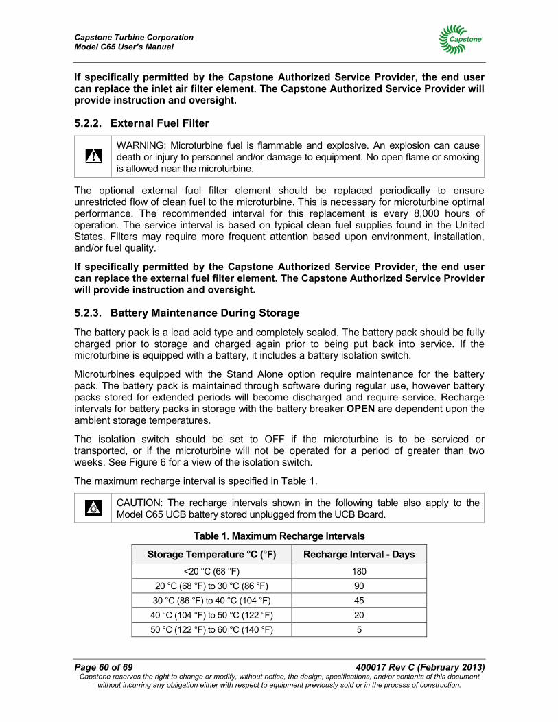
Capstone Turbine Corporation Model C65 User’s Manual
Page 60 of 69 400017 Rev C (February 2013) Capstone reserves the right to change or modify, without notice, the design, specifications, and/or contents of this document
without incurring any obligation either with respect to equipment previously sold or in the process of construction.
If specifically permitted by the Capstone Authorized Service Provider, the end user can replace the inlet air filter element. The Capstone Authorized Service Provider will provide instruction and oversight.
5.2.2. External Fuel Filter
WARNING: Microturbine fuel is flammable and explosive. An explosion can cause death or injury to personnel and/or damage to equipment. No open flame or smoking is allowed near the microturbine.
The optional external fuel filter element should be replaced periodically to ensure unrestricted flow of clean fuel to the microturbine. This is necessary for microturbine optimal performance. The recommended interval for this replacement is every 8,000 hours of operation. The service interval is based on typical clean fuel supplies found in the United States. Filters may require more frequent attention based upon environment, installation, and/or fuel quality.
If specifically permitted by the Capstone Authorized Service Provider, the end user can replace the external fuel filter element. The Capstone Authorized Service Provider will provide instruction and oversight.
5.2.3. Battery Maintenance During Storage
The battery pack is a lead acid type and completely sealed. The battery pack should be fully charged prior to storage and charged again prior to being put back into service. If the microturbine is equipped with a battery, it includes a battery isolation switch.
Microturbines equipped with the Stand Alone option require maintenance for the battery pack. The battery pack is maintained through software during regular use, however battery packs stored for extended periods will become discharged and require service. Recharge intervals for battery packs in storage with the battery breaker OPEN are dependent upon the ambient storage temperatures.
The isolation switch should be set to OFF if the microturbine is to be serviced or transported, or if the microturbine will not be operated for a period of greater than two weeks. See Figure 6 for a view of the isolation switch.
The maximum recharge interval is specified in Table 1.
CAUTION: The recharge intervals shown in the following table also apply to the Model C65 UCB battery stored unplugged from the UCB Board.
Table 1. Maximum Recharge Intervals
Storage Temperature °C (°F) Recharge Interval - Days <20 °C (68 °F) 180
20 °C (68 °F) to 30 °C (86 °F) 90 30 °C (86 °F) to 40 °C (104 °F) 45 40 °C (104 °F) to 50 °C (122 °F) 20 50 °C (122 °F) to 60 °C (140 °F) 5
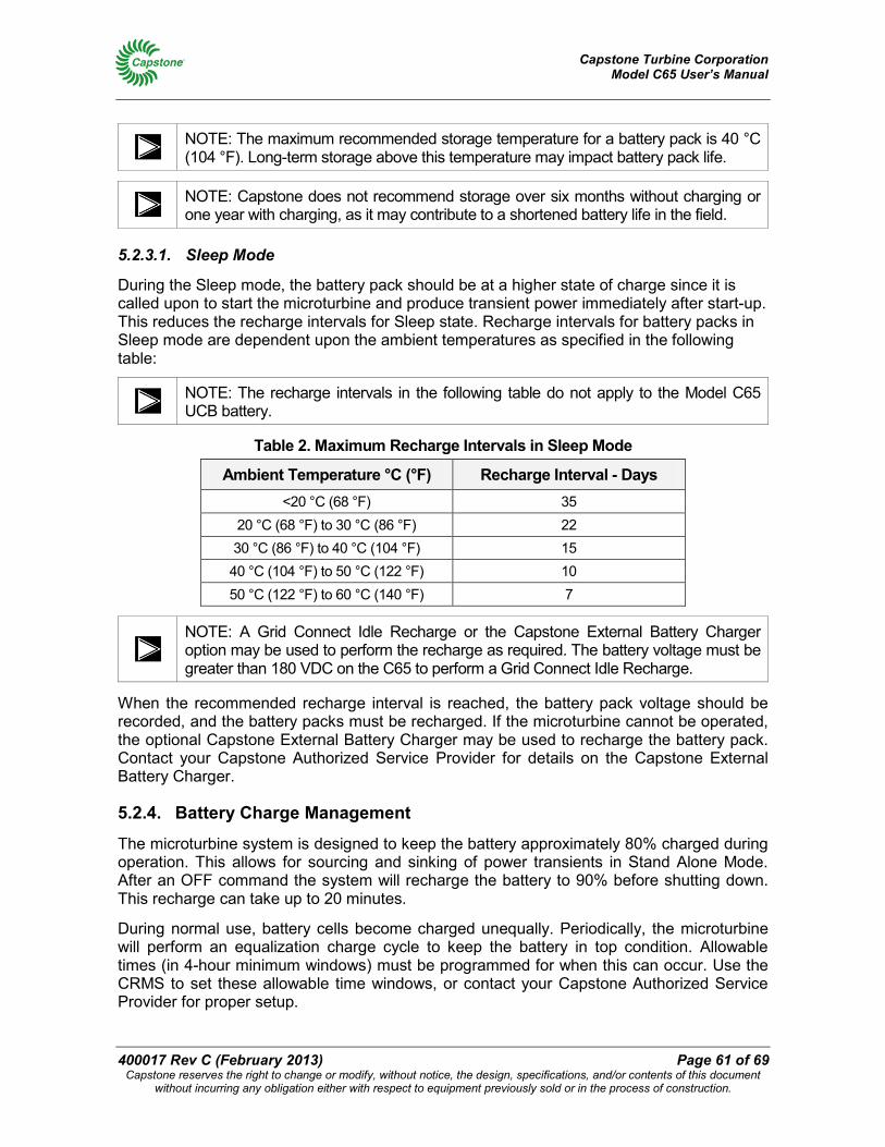
Capstone Turbine Corporation Model C65 User’s Manual
400017 Rev C (February 2013) Page 61 of 69 Capstone reserves the right to change or modify, without notice, the design, specifications, and/or contents of this document
without incurring any obligation either with respect to equipment previously sold or in the process of construction.
NOTE: The maximum recommended storage temperature for a battery pack is 40 °C (104 °F). Long-term storage above this temperature may impact battery pack life.
NOTE: Capstone does not recommend storage over six months without charging or one year with charging, as it may contribute to a shortened battery life in the field.
5.2.3.1. Sleep Mode
During the Sleep mode, the battery pack should be at a higher state of charge since it is called upon to start the microturbine and produce transient power immediately after start-up. This reduces the recharge intervals for Sleep state. Recharge intervals for battery packs in Sleep mode are dependent upon the ambient temperatures as specified in the following table:
NOTE: The recharge intervals in the following table do not apply to the Model C65 UCB battery.
Table 2. Maximum Recharge Intervals in Sleep Mode
Ambient Temperature °C (°F) Recharge Interval - Days <20 °C (68 °F) 35
20 °C (68 °F) to 30 °C (86 °F) 22 30 °C (86 °F) to 40 °C (104 °F) 15 40 °C (104 °F) to 50 °C (122 °F) 10 50 °C (122 °F) to 60 °C (140 °F) 7
NOTE: A Grid Connect Idle Recharge or the Capstone External Battery Charger option may be used to perform the recharge as required. The battery voltage must be greater than 180 VDC on the C65 to perform a Grid Connect Idle Recharge.
When the recommended recharge interval is reached, the battery pack voltage should be recorded, and the battery packs must be recharged. If the microturbine cannot be operated, the optional Capstone External Battery Charger may be used to recharge the battery pack. Contact your Capstone Authorized Service Provider for details on the Capstone External Battery Charger.
5.2.4. Battery Charge Management
The microturbine system is designed to keep the battery approximately 80% charged during operation. This allows for sourcing and sinking of power transients in Stand Alone Mode. After an OFF command the system will recharge the battery to 90% before shutting down. This recharge can take up to 20 minutes.
During normal use, battery cells become charged unequally. Periodically, the microturbine will perform an equalization charge cycle to keep the battery in top condition. Allowable times (in 4-hour minimum windows) must be programmed for when this can occur. Use the CRMS to set these allowable time windows, or contact your Capstone Authorized Service Provider for proper setup.
Capstone Turbine Corporation Model C65 User’s Manual
Page 62 of 69 400017 Rev C (February 2013) Capstone reserves the right to change or modify, without notice, the design, specifications, and/or contents of this document
without incurring any obligation either with respect to equipment previously sold or in the process of construction.
5.2.4.1. Manual Battery Pack Equalization Charge
If the system is not operating or is in storage, a manual equalization charge may be commanded if the system is connected to the electric utility grid (refer to Grid Connect Operation on page 26). Initiate a Battery Pack Equalization charge as follows:
Using Display Panel:
1. System Data Menu > Enter Password. The factory default User level password is 87712370.
2. Navigate to Stand Alone > Local Batt Chg > Enable. Press Accept.
Using CRMS or APS – CRMS:
1. Select Settings > Battery Management. Set Equalization Charge Slider to Enable.
NOTE: A battery pack equalization charge can take up to 4 hours.
5.2.5. Warranty
Each microturbine ships with a standard warranty. Extended warranties are available. Contact your Authorized Service Provider for details on Capstone warranty terms and conditions.
6. Troubleshooting This section details basic troubleshooting procedures and steps that the user can perform on the Capstone Microturbine without accessing the inside of the enclosure. Only Capstone Authorized Service Providers are permitted access to the inside of the enclosure.
ELECTRICAL WARNING: The microturbine system produces and contains high voltage. High voltage can injure or kill. Obey all safety procedures when you work around electrical equipment. Only Capstone Authorized Service Providers are permitted access to the inside of the enclosure.
6.1. Incidents The microturbine continuously monitors a wide variety of parameters both internal and external to the system. An incident occurs whenever a measured parameter falls outside prescribed limits. Incidents include (but are not limited to) low fuel pressure, utility interruptions, and utility over voltages.
6.2. Incident System Severity Levels When the system detects an incident, it may take one of several actions, depending on the system severity level (SSL). Actions range from simply noting the occurrence and continuing to operate, to immediate shutdown of the system. The action taken depends upon the severity of the incident. The system will attempt a restart only if the severity of the incident will allow it.
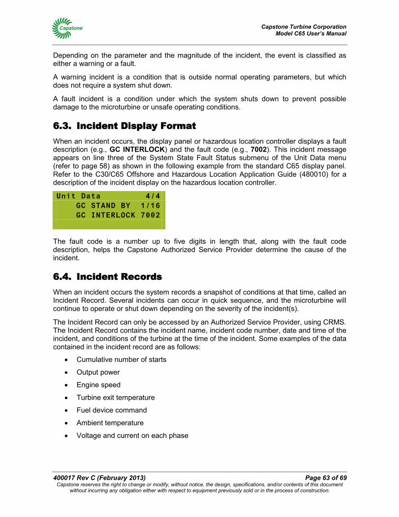
Capstone Turbine Corporation Model C65 User’s Manual
400017 Rev C (February 2013) Page 63 of 69 Capstone reserves the right to change or modify, without notice, the design, specifications, and/or contents of this document
without incurring any obligation either with respect to equipment previously sold or in the process of construction.
Depending on the parameter and the magnitude of the incident, the event is classified as either a warning or a fault.
A warning incident is a condition that is outside normal operating parameters, but which does not require a system shut down.
A fault incident is a condition under which the system shuts down to prevent possible damage to the microturbine or unsafe operating conditions.
6.3. Incident Display Format When an incident occurs, the display panel or hazardous location controller displays a fault description (e.g., GC INTERLOCK) and the fault code (e.g., 7002). This incident message appears on line three of the System State Fault Status submenu of the Unit Data menu (refer to page 58) as shown in the following example from the standard C65 display panel. Refer to the C30/C65 Offshore and Hazardous Location Application Guide (480010) for a description of the incident display on the hazardous location controller.
Unit Data 4/4 GC STAND BY 1/16 GC INTERLOCK 7002
The fault code is a number up to five digits in length that, along with the fault code description, helps the Capstone Authorized Service Provider determine the cause of the incident.
6.4. Incident Records When an incident occurs the system records a snapshot of conditions at that time, called an Incident Record. Several incidents can occur in quick sequence, and the microturbine will continue to operate or shut down depending on the severity of the incident(s).
The Incident Record can only be accessed by an Authorized Service Provider, using CRMS. The Incident Record contains the incident name, incident code number, date and time of the incident, and conditions of the turbine at the time of the incident. Some examples of the data contained in the incident record are as follows:
• Cumulative number of starts
• Output power
• Engine speed
• Turbine exit temperature
• Fuel device command
• Ambient temperature
• Voltage and current on each phase
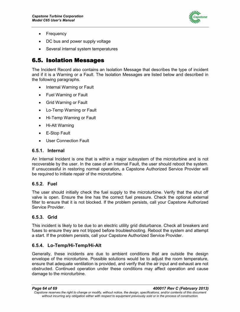
Capstone Turbine Corporation Model C65 User’s Manual
Page 64 of 69 400017 Rev C (February 2013) Capstone reserves the right to change or modify, without notice, the design, specifications, and/or contents of this document
without incurring any obligation either with respect to equipment previously sold or in the process of construction.
• Frequency
• DC bus and power supply voltage
• Several internal system temperatures
6.5. Isolation Messages The Incident Record also contains an Isolation Message that describes the type of incident and if it is a Warning or a Fault. The Isolation Messages are listed below and described in the following paragraphs.
• Internal Warning or Fault
• Fuel Warning or Fault
• Grid Warning or Fault
• Lo-Temp Warning or Fault
• Hi-Temp Warning or Fault
• Hi-Alt Warning
• E-Stop Fault
• User Connection Fault
6.5.1. Internal
An Internal Incident is one that is within a major subsystem of the microturbine and is not recoverable by the user. In the case of an Internal Fault, the user should reboot the system. If unsuccessful in restoring normal operation, a Capstone Authorized Service Provider will be required to initiate repair of the microturbine.
6.5.2. Fuel
The user should initially check the fuel supply to the microturbine. Verify that the shut off valve is open. Ensure the line has the correct fuel pressure. Check the optional external filter to ensure that it is not blocked. If the problem persists, call your Capstone Authorized Service Provider.
6.5.3. Grid
This incident is likely to be due to an electric utility grid disturbance. Check all breakers and fuses to ensure they are not tripped before troubleshooting. Reboot the system and attempt a start. If the problem persists, call your Capstone Authorized Service Provider.
6.5.4. Lo-Temp/Hi-Temp/Hi-Alt
Generally, these incidents are due to ambient conditions that are outside the design envelope of the microturbine. Possible solutions would be to adjust the room temperature, ensure that adequate ventilation is provided, and verify that the air input and exhaust are not obstructed. Continued operation under these conditions may affect operation and cause damage to the microturbine.
Capstone Turbine Corporation Model C65 User’s Manual
400017 Rev C (February 2013) Page 65 of 69 Capstone reserves the right to change or modify, without notice, the design, specifications, and/or contents of this document
without incurring any obligation either with respect to equipment previously sold or in the process of construction.
6.5.5. E-Stop
If the event display reads MANUAL E-STOP, fix the original problem that initiated the E-Stop, as this fault must be cleared before it is safe to resume operation. Next, check the optional emergency stop button and verify that it has been activated. If it has, reset the button, cycle power off to the microturbine for 30 seconds, and turn the power back on. The fault should clear, and the system should resume operation. If it does not, call your Capstone Authorized Service Provider.
6.5.6. User Conn (User Connection)
User Connection incidents can be due to incorrect Grid Connect / Stand Alone settings, mode transition faults when in Dual Mode operation, or to indicate a possible problem with external equipment connected to the microturbine.
6.6. Basic Troubleshooting Procedures Basic Troubleshooting procedures are presented in the following paragraphs.
WARNING: Users do not perform some of the following microturbine troubleshooting procedures, but it is important for users to be aware of them. Only Capstone Authorized Service Providers are permitted access to the inside of the enclosure. Users are permitted to open the User Connection Bay to access the user port.
6.6.1. Troubleshooting Procedures for Standard C65 Model
6.6.1.1. No Lights on Display Panel
If no lights are present on the Display Panel, troubleshoot as follows:
WARNING: Only Capstone Authorized Service Providers can perform the following troubleshooting steps.
1. If Stand Alone equipped, open the front door. Make sure the Battery Isolation switch is set to ON. Then press the BATT START button on the Display Panel.
2. If Grid Connect, verify electric utility grid voltage is present on the phase terminals in the Power Bay.
6.6.1.2. No Attempt to Start after ON Command
If no attempt is made to Start, after an ON Command, troubleshoot as follows:
1. Verify that the current communication device (Display Panel or user port) is the control device. Refer to Control Device Authority and Priority on page 25.
2. Verify that the ON command is consistent with the currently active dispatch mode. Refer to the section on Display Panel Menus for more data.
Capstone Turbine Corporation Model C65 User’s Manual
Page 66 of 69 400017 Rev C (February 2013) Capstone reserves the right to change or modify, without notice, the design, specifications, and/or contents of this document
without incurring any obligation either with respect to equipment previously sold or in the process of construction.
6.6.1.3. Start Attempt Fails
If a Start Attempt fails, troubleshoot as follows:
1. If the system attempts but fails to start, an incident code will be registered as described in the previous sections.
2. The troubleshooting procedure is the same as for Unexpected Shut Down or Warning in the next section.
6.6.1.4. Low Power Output
If Low Power Output is perceived, troubleshoot as follows:
1. Check your inlet fuel supply. Verify that the fuel isolation valve is open, and that the inlet fuel line has the correct fuel pressure.
2. Check your external fuel filter. Verify that the external fuel filter (if installed) is not blocked.
3. Check your inlet airflow, ventilation, and exhaust airflow. Verify that the inlet airflow and the exhaust airflow are not obstructed.
4. Check your ambient operating conditions and verify the expected power output due to temperature, altitude and other derating factors. Verify that ambient conditions are not outside the microturbine design envelope.
6.6.1.5. Unexpected Shut Down or Warning
When a warning incident occurs, no action is required by the user. When a fault incident occurs, the troubleshooting steps are as follows:
1. Attempt to restart. If unsuccessful, then verify the fuel, air, and electrical supply to the microturbine.
2. Attempt to restart. If unsuccessful, then enter the user password and reboot the system through the Display Panel.
3. Attempt to restart. If unsuccessful, then cycle the power by shutting off power to the system, waiting 30 seconds, and turning the power back on.
4. Attempt to restart. If unsuccessful, then note the event number listed on the Display Window, and then call your Capstone Authorized Service Provider for assistance.
When required, your Capstone Authorized Service Provider will determine whether the event noted requires a service call or if the user can perform fault correction on site. Generally, the Service Provider will initiate a service call for Internal Fault codes. In most other cases, the Service Provider will recommend a possible course of action to return the microturbine to operational status.
6.6.2. Troubleshooting Procedures for C65 Hazardous Location Model
Refer to the C30/C65 Offshore and Hazardous Location Application Guide (480010) for troubleshooting procedures that apply to the hazardous location microturbine.
Capstone Turbine Corporation Model C65 User’s Manual
400017 Rev C (February 2013) Page 67 of 69 Capstone reserves the right to change or modify, without notice, the design, specifications, and/or contents of this document
without incurring any obligation either with respect to equipment previously sold or in the process of construction.
Notes
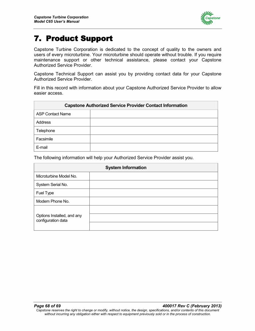
Capstone Turbine Corporation Model C65 User’s Manual
Page 68 of 69 400017 Rev C (February 2013) Capstone reserves the right to change or modify, without notice, the design, specifications, and/or contents of this document
without incurring any obligation either with respect to equipment previously sold or in the process of construction.
7. Product Support Capstone Turbine Corporation is dedicated to the concept of quality to the owners and users of every microturbine. Your microturbine should operate without trouble. If you require maintenance support or other technical assistance, please contact your Capstone Authorized Service Provider.
Capstone Technical Support can assist you by providing contact data for your Capstone Authorized Service Provider.
Fill in this record with information about your Capstone Authorized Service Provider to allow easier access.
Capstone Authorized Service Provider Contact Information
ASP Contact Name
Address
Telephone
Facsimile
The following information will help your Authorized Service Provider assist you.
System Information
Microturbine Model No.
System Serial No.
Fuel Type
Modem Phone No.
Options Installed, and any configuration data
Capstone Turbine Corporation Model C65 User’s Manual
400017 Rev C (February 2013) Page 69 of 69 Capstone reserves the right to change or modify, without notice, the design, specifications, and/or contents of this document
without incurring any obligation either with respect to equipment previously sold or in the process of construction.
Notes Event Date Hours Starts
Commissioning