Embed Size (px)
Citation preview
8/11/2019 Capping Manual Rsheetpile
http://slidepdf.com/reader/full/capping-manual-rsheetpile 1/54

8/11/2019 Capping Manual Rsheetpile
http://slidepdf.com/reader/full/capping-manual-rsheetpile 2/54
WORLDWIDEDEALERNETWORK
GLOBALUPPLY,
LOCALUPPORT.
CONTACTSDawson Construction Plant LtdChesney Wold.Bleak Hall,Milton Keynes,MK6 1NE, EnglandTel: +44 (0) 1908 240300
Fax: +44 (0) 1908 240222
www.dcpuk.com
------------------------------------------------------------------------
------------------------------------------------------------------------
------------------------------------------------------------------------
------------------------------------------------------------------------
------------------------------------------------------------------------
------------------------------------------------------------------------
------------------------------------------------------------------------
------------------------------------------------------------------------
LEADING EDGE TECHNOLOGY
8/11/2019 Capping Manual Rsheetpile
http://slidepdf.com/reader/full/capping-manual-rsheetpile 3/5403
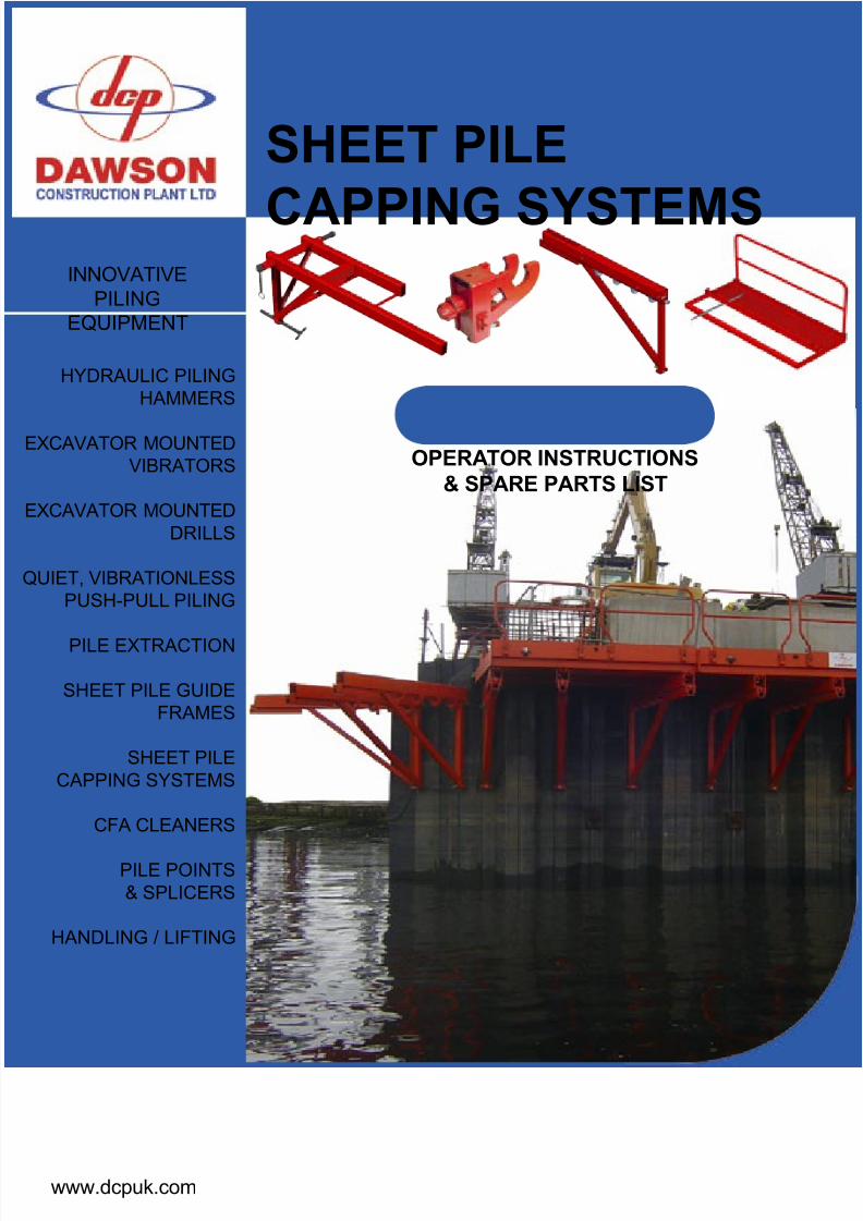
04 Capping System
06 Introduction The Redeb Support Bracket /The Multi-Pile Soft Shutter Panel
09 Limitations of the Redeb Bracket
Safe Working Load / Angle of Sheet Pile Web / Fixing width
10 Limitations of the Soft Panels
11 Installation of the Redeb Support Bracket
12 Installation of the Soft Panels
15 Removal of the Soft Panels
16 Removal of the Redeb Support Bracket
17 Torque Wrench
18 Safety Points & Maintenance
21 Technical Specication
19 Location buttons
22 Component Parts Lists Soft Panel (2.5m) / Redeb Bracket – RSB500 / 600 / 700
26 Redeb Bracket requirements for various sheet pile sections. Table 1 / Table 2
29 MDBS Redeb Support Bracket 37 Heavy Duty Capping
CONTENTS
8/11/2019 Capping Manual Rsheetpile
http://slidepdf.com/reader/full/capping-manual-rsheetpile 4/54
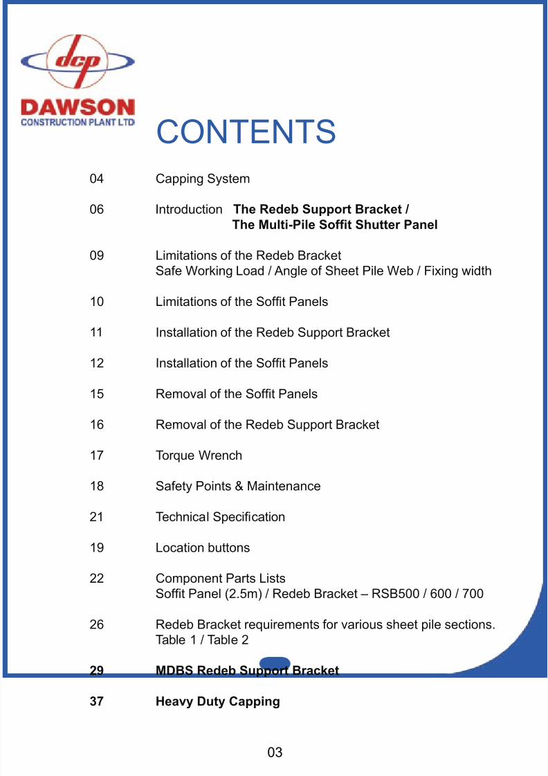
CAPPING SYSTEMEXPOSED PILE SECTIONScribe a setting out line for theRSB hard points 140mm below thebottom level of the cap.
140
DAWSON’S REDEB SUPPORTBRACKET POSITIONED
Lower brackets into position.Torque jacking bolts to 180Nmand level.
DAWSON SOFIT PANELSPOSITIONEDEnsure at least 2 brackets supporteach panel. Lower the sot panelsinto postion with the front edgetight against the pile.Use timberwedges, to drive the panel forwardagainst the sheet pile face then lift
and lock guard rail. (not shown)
8/11/2019 Capping Manual Rsheetpile
http://slidepdf.com/reader/full/capping-manual-rsheetpile 5/5405
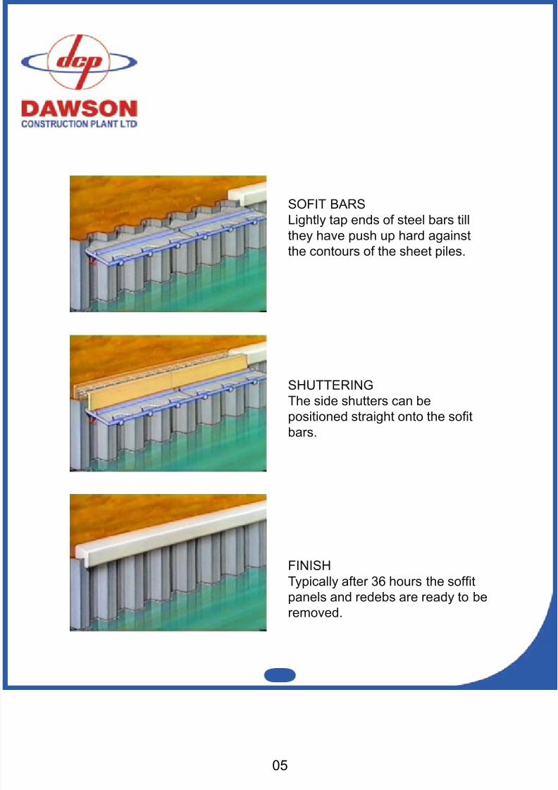
SHUTTERINGThe side shutters can bepositioned straight onto the sotbars.
SOFIT BARSLightly tap ends of steel bars tillthey have push up hard againstthe contours of the sheet piles.
FINISHTypically after 36 hours the softpanels and redebs are ready to beremoved.
8/11/2019 Capping Manual Rsheetpile
http://slidepdf.com/reader/full/capping-manual-rsheetpile 6/54
INTRODUCTIONThe only purpose-made sheet pile capping system available is fasterand more cost effective than any on-site ‘lash ups’.
The Redeb Bracket and Soft Panels can be assembled and re-used byunskilled labour. Welding or cutting of piles is not necessary. It rendersobsolete the use of individual plywood soft panels cut out to match pile
pans.
Traditional ‘old fashioned’ methods use brackets welded against piles tocarry longitudinal beams and shuttering timber. Such brackets haveultimately to be burned off, their stubs ground down and the pilespaintwork made good.
All this trouble is avoided using this pile capping system.
Example
A concrete cap, approx. size 1.2m high by 0.9m wide and 275m in lengthwas completed in four weeks. A 15 metre concrete pour was made everyday. 5 no. per week using a total of 45 no. Redebs and 18 no. 2.5mPanels (e.g. 3 no. 15 metre lengths).
The above resulted in a time saving of over 2 weeks compared with‘traditional’ methods.
THE REDEB SUPPORT BRACKET
The Redeb Support Bracket provides a cheaper, simpler and faster method of supporting the soft shutter for the construction of aconcrete cap on “U” and “Z” shaped sheet piles.The Redeb Support Bracket is a light yet robust piece of equipment designed to give many years of trouble free serviceproviding it is correctly used and maintained. It is designed solelyfor use on steel sheet piles.
8/11/2019 Capping Manual Rsheetpile
http://slidepdf.com/reader/full/capping-manual-rsheetpile 7/5407
Sheet piles are generally capped for Aesthetic purposes. Theconcrete cap serves to mask the inevitable irregularities in sheetpile length, penetration depth and line. They may also be used asa support for a railing or safety barrier.
There are three models of Redeb bracket - the RSB500, RSB600and RSB700. The RSB500 & RSB600 models are designed to
work on both ‘Z’ type and ‘U’ type sheet pile sections. TheRSB500 covering narrower pile sections than the RSB600. TheRSB700 is exclusively designed to work with the Hoesch Larssen700mm wide ‘U’ piles and Arcelor 750mm wide ‘U’ piles. Withthese models most sheet pile sections can be accommodated withincertain limitations.
THE MULTI PILE SOFFIT SHUTTER PANEL
There are two standard soft shutter panels for all normal pilecaps and a lot of abnormal ones as well.
Advantages
1. Very quick set up - saves time
2. Simple use for - saves money unskilled labour
3. Eliminates wastage - saves materials of consumable materials
4. Provides a formal system - saves money tried and proven as opposed to one off on-site lashups
5. Re-useable for all - maximise repeat shapes of sheet pile usage
8/11/2019 Capping Manual Rsheetpile
http://slidepdf.com/reader/full/capping-manual-rsheetpile 8/54
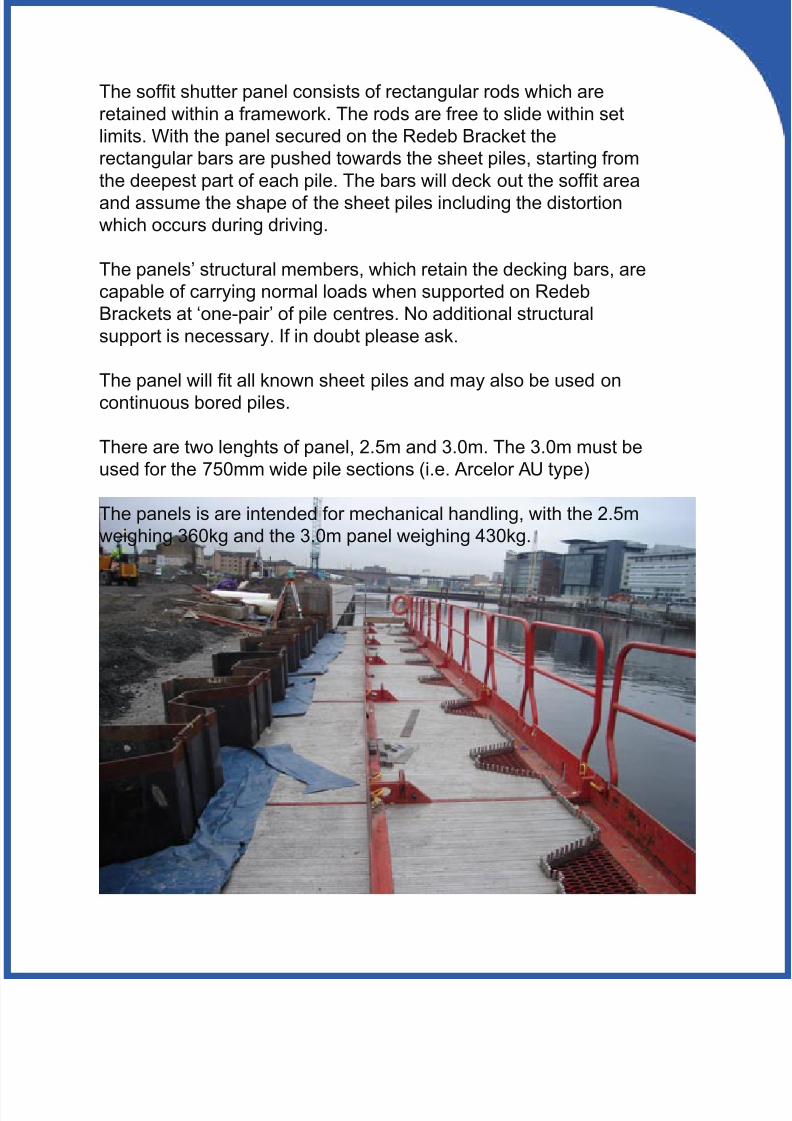
The soft shutter panel consists of rectangular rods which areretained within a framework. The rods are free to slide within setlimits. With the panel secured on the Redeb Bracket therectangular bars are pushed towards the sheet piles, starting fromthe deepest part of each pile. The bars will deck out the soft areaand assume the shape of the sheet piles including the distortionwhich occurs during driving.
The panels’ structural members, which retain the decking bars, arecapable of carrying normal loads when supported on RedebBrackets at ‘one-pair’ of pile centres. No additional structuralsupport is necessary. If in doubt please ask.
The panel will t all known sheet piles and may also be used oncontinuous bored piles.
There are two lenghts of panel, 2.5m and 3.0m. The 3.0m must beused for the 750mm wide pile sections (i.e. Arcelor AU type)
The panels is are intended for mechanical handling, with the 2.5mweighing 360kg and the 3.0m panel weighing 430kg.
8/11/2019 Capping Manual Rsheetpile
http://slidepdf.com/reader/full/capping-manual-rsheetpile 9/5409
Although the Redeb Support Bracket is suitable in the majority of pile cap situations there are certain limitations which must betaken into account before specifying the equipment for any given
job. (If in doubt consult the manufacturer).
SAFE WORKING LOAD
The S.W.L. of the Redeb is specied in terms of a point load onthe bracket at a certain location i.e. a load applied on the arms of the bracket at a distance of 310mm from the centre of the HardPoints. (see page 21 for technical specication) a. Bracket xed on interlocks of ‘U’ type sheet piles - S.W.L. 2000 kgs. b. Bracket xed on any inclined webs of ‘U’ or ‘Z’ type sheet piles having a minimum included angle of 55º - S.W.L. 1500 kgs.
This means that the maximum S.W.L. on any ‘Z’ (Frodingham)
type sheet pile will be 1500 kgs.ANGLE OF SHEET PILE WEB
The ideal xing position for the Redeb bracket is betweeninterlocks on a single ‘U’ type sheet pile. The interlocks areextremely rigid and the ‘xing face’ is perpendicular to the steelhard points. However, in many cases the xing face is at an angleto the hard point centre line. This occurs on ‘Z’ (Frodingham)
type sheet piles and on narrow ‘U’ type sheets when the Redeb istoo wide to t between interlocks.Under these conditions due consideration must be given to the angleinvolved and the choice of Hard Point type.
a. The Redeb can not be used on sheet piles where the angle betweenthe ‘xing face’ (usually the web) and the Hard Point centre line isless than 55º.
b. If this angle is between 55º and 65º then 70º Hard Points must be
utilised. c. Where the angle is above 65º then standard 90º Hard Points should
be used.
LIMITATIONS OF THE
REDEB BRACKET
8/11/2019 Capping Manual Rsheetpile
http://slidepdf.com/reader/full/capping-manual-rsheetpile 10/54
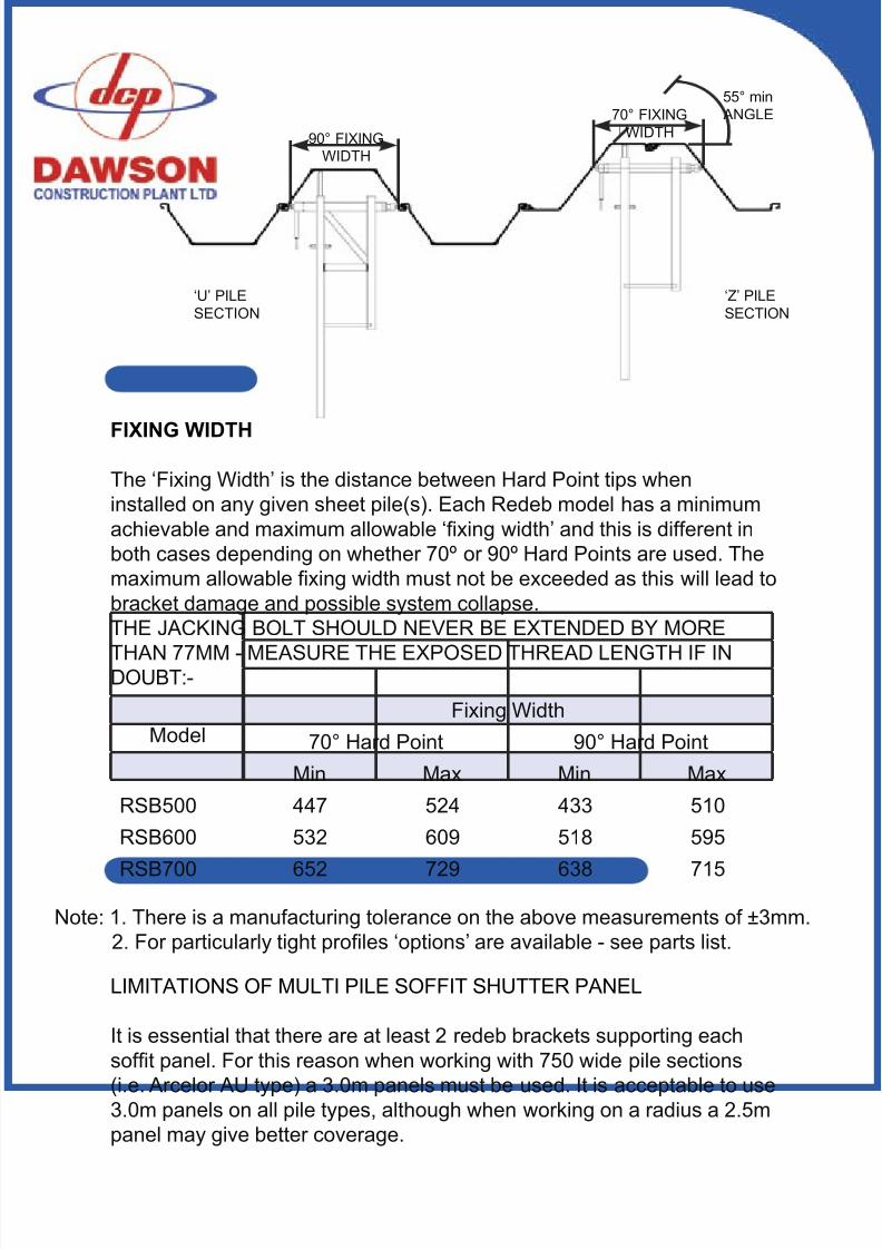
90° FIXINGWIDTH
70° FIXINGWIDTH
55° min ANGLE
‘U’ PILESECTION
‘Z’ PILESECTION
FIXING WIDTH
The ‘Fixing Width’ is the distance between Hard Point tips wheninstalled on any given sheet pile(s). Each Redeb model has a minimumachievable and maximum allowable ‘xing width’ and this is different inboth cases depending on whether 70º or 90º Hard Points are used. Themaximum allowable xing width must not be exceeded as this will lead tobracket damage and possible system collapse.THE JACKING BOLT SHOULD NEVER BE EXTENDED BY MORE
THAN 77MM - MEASURE THE EXPOSED THREAD LENGTH IF INDOUBT:-
ModelFixing Width
70° Hard Point 90° Hard Point
Min Max Min MaxRSB500 447 524 433 510RSB600 532 609 518 595
RSB700 652 729 638 715
Note: 1. There is a manufacturing tolerance on the above measurements of ±3mm. 2. For particularly tight proles ‘options’ are available - see parts list.
LIMITATIONS OF MULTI PILE SOFFIT SHUTTER PANEL
It is essential that there are at least 2 redeb brackets supporting eachsoft panel. For this reason when working with 750 wide pile sections
(i.e. Arcelor AU type) a 3.0m panels must be used. It is acceptable to use3.0m panels on all pile types, although when working on a radius a 2.5mpanel may give better coverage.
8/11/2019 Capping Manual Rsheetpile
http://slidepdf.com/reader/full/capping-manual-rsheetpile 11/54
1. Scribe a setting out line at the correct height on the pan of every pile.Using a centre punch, mark the Hard Point positions on this line. Allow adistance of 40mm from the Hard Point centres to the top surface of thebracket. Allow a distance of 100mm for the thickness of the soft paneli.e. a total of 140mm.
Note:
a. To save time this marking out procedure need only be done on everyalternative pile pan. Intermediate brackets can then be positioned laterusing the installed brackets for reference.
b. On sheet pile sections with particularly steep web angles it may bebenecial to drill a small hole in the pile instead of using a centre punchi.e. Ø4mm x 3mm deep using a cordless drill. This will ease installationconsiderably.
2. Lower the bracket into position and with the Quick Release mechanismin its extended position, with the release lever pointing downwards,unscrew the Jacking Bolt at the other end of the bracket with a torquewrench until the required torque is reached (180Nm). By doing this, thetwo steel Hard Points will be pressed into the sides of the piles.
3. The axis of the bracket is now at the correct level. The arms of thebracket have to be leveled by adjusting the Lower Adjusting Bolt at thebase of the leg. Place a spirit level on a horizontal arm of the bracket to
obtain the correct level.
4. Repeat this procedure until a bracket is correctly positioned in everyalternate pile pan.
5. The intermediate brackets can now be positioned by leveling themup to a straight edge set between two previously positioned brackets.
6. Once all the brackets are secured, go back and check that they allhave the correct torque. The brackets are now ready to receive the softshuttering.
INSTALLATION OFTHE REDEB
SUPPORT BRACKET
11
8/11/2019 Capping Manual Rsheetpile
http://slidepdf.com/reader/full/capping-manual-rsheetpile 12/54
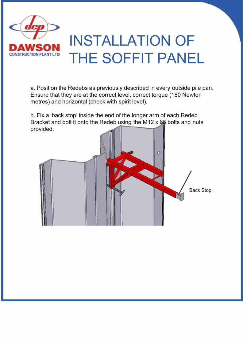
a. Position the Redebs as previously described in every outside pile pan.Ensure that they are at the correct level, correct torque (180 Newtonmetres) and horizontal (check with spirit level).
b. Fix a ‘back stop’ inside the end of the longer arm of each RedebBracket and bolt it onto the Redeb using the M12 x 65 bolts and nutsprovided.
INSTALLATION OF
THE SOFFIT PANEL
Back Stop
8/11/2019 Capping Manual Rsheetpile
http://slidepdf.com/reader/full/capping-manual-rsheetpile 13/5413
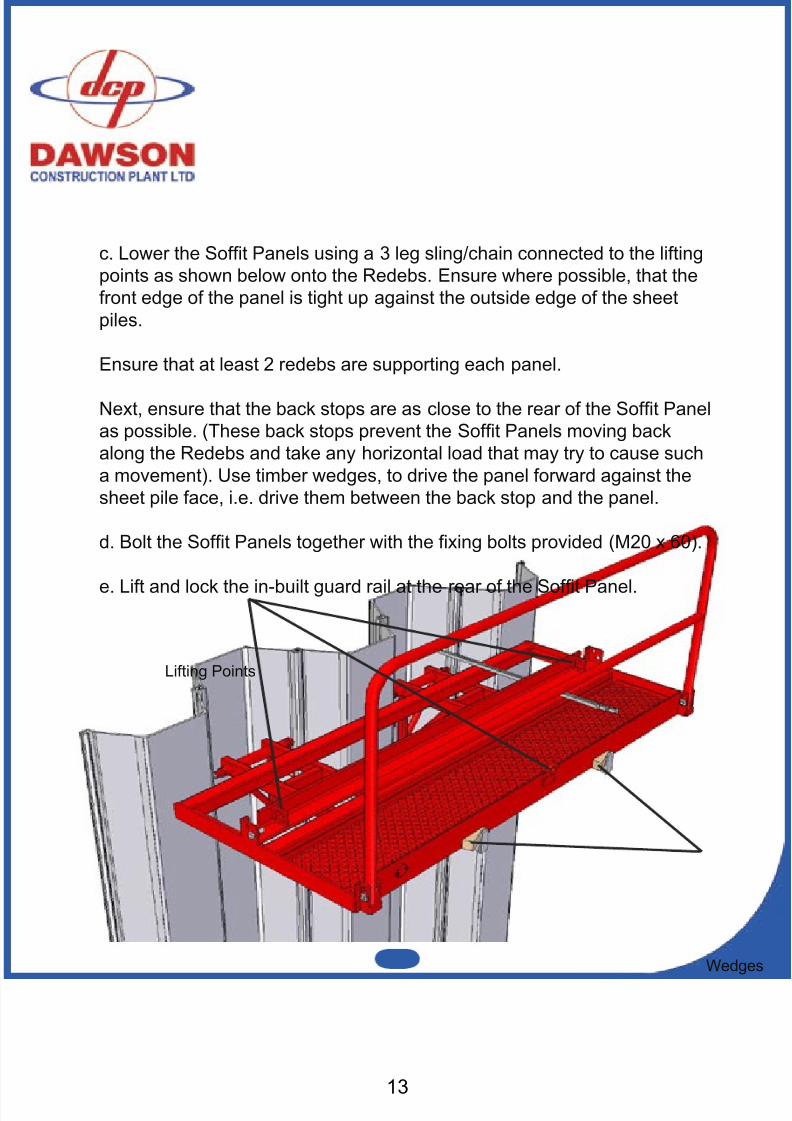
c. Lower the Soft Panels using a 3 leg sling/chain connected to the liftingpoints as shown below onto the Redebs. Ensure where possible, that thefront edge of the panel is tight up against the outside edge of the sheetpiles.
Ensure that at least 2 redebs are supporting each panel.
Next, ensure that the back stops are as close to the rear of the Soft Panelas possible. (These back stops prevent the Soft Panels moving backalong the Redebs and take any horizontal load that may try to cause sucha movement). Use timber wedges, to drive the panel forward against thesheet pile face, i.e. drive them between the back stop and the panel.
d. Bolt the Soft Panels together with the xing bolts provided (M20 x 60).
e. Lift and lock the in-built guard rail at the rear of the Soft Panel.
Wedges
Lifting Points
8/11/2019 Capping Manual Rsheetpile
http://slidepdf.com/reader/full/capping-manual-rsheetpile 14/54
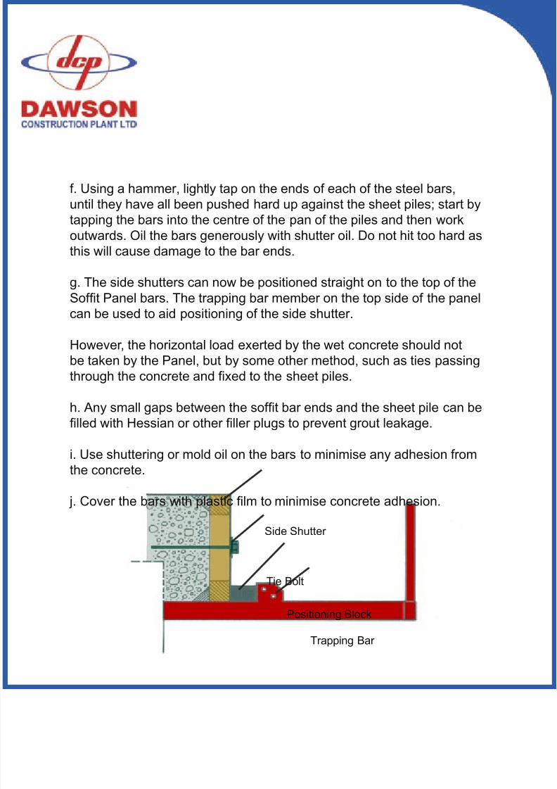
f. Using a hammer, lightly tap on the ends of each of the steel bars,until they have all been pushed hard up against the sheet piles; start bytapping the bars into the centre of the pan of the piles and then workoutwards. Oil the bars generously with shutter oil. Do not hit too hard asthis will cause damage to the bar ends.
g. The side shutters can now be positioned straight on to the top of theSoft Panel bars. The trapping bar member on the top side of the panelcan be used to aid positioning of the side shutter.
However, the horizontal load exerted by the wet concrete should notbe taken by the Panel, but by some other method, such as ties passingthrough the concrete and xed to the sheet piles.
h. Any small gaps between the soft bar ends and the sheet pile can belled with Hessian or other ller plugs to prevent grout leakage.
i. Use shuttering or mold oil on the bars to minimise any adhesion fromthe concrete.
j. Cover the bars with plastic lm to minimise concrete adhesion.
Side Shutter
Tie Bolt
Positioning Block
Trapping Bar
8/11/2019 Capping Manual Rsheetpile
http://slidepdf.com/reader/full/capping-manual-rsheetpile 15/5415
After 36 hours the Soft Panels and Redebs are ready to be stripped.From underneath the concrete cap, undo the levelling bolt on the Redeba few turns to slightly tilt the Soft Panel.
Connect the lifting chain to the lifting points (see panel assembly drawingat the rear of this manual) and ease the panel outwards.
The lifting of the Soft Panel will automatically cause free movement of the steel bars, and will help to shed any grout. With a stiff brush sweepall concrete grout and debris off the bars to ensure no concrete becomesencrusted. The sooner the panels are scrubbed and cleaned after theconcrete pour, the easier and quicker it is to prepare them for re-use.The panels will be supplied with as many bars in them as possible,which ensures a minimum of grout leakage between the bars. However,after a number of concrete pours, the free movement of the bars inthe panel may become restricted and in practice this may be easedby removing one or two of the bars. Any ‘gaps’ caused by this willimmediately be taken up by the remaining bars.
Walkways and safety rails are in an integral part of the 2.5m Soft Panel.
Lifting points on the panels are provided for this sling as shown on theparts list.
Proper use of the sling with the two equal legs to the end of the paneland the third shorter leg to the centrally positioned chain at the rearshould ensure that the panel remains level during setting up andstripping of the equipment.
N.B. Whilst stacking or unstacking panels into or out of the transportationstillage it may be an advantage to use only the end lifting points allowingthe panel to tilt.
REMOVAL OF THE
SOFFIT PANEL
8/11/2019 Capping Manual Rsheetpile
http://slidepdf.com/reader/full/capping-manual-rsheetpile 16/54
The cap rarely serves any structural purpose and as such it is generallyaccepted that the Redeb Support Bracket can be removed 36 hours after the concrete pour. Providing some cement had been used in theconcrete, the concrete cap will certainly be strong enough to supportitself after this time and enable the Redebs and shuttering to be stripped!
This saves time and money. To remove the bracket:-1. Back off the tension on the Lower Adjusting Bolt to allow the bracketto tilt down at a slight angle. This will ease the removal of the softshuttering.
2. Having removed all shuttering, release some tension from the JackingBolt using a spanner. Secure the Redeb by some means, possiblya rope, then pull the Cam Release lever to retract the Cam Release
mechanism. At this point the bracket will fall away from the sheet piles sopay attention to its movement and weight.
3. Having removed the bracket ensure it is cleaned, checked andlubricated before re-use as described under the maintenance section ofthese instructions.
REMOVAL OF THEREDEB SUPPORT
BRACKET
8/11/2019 Capping Manual Rsheetpile
http://slidepdf.com/reader/full/capping-manual-rsheetpile 17/5417
It is important to use a torque wrench set to a reading of 180 Nm(Newton-metres) to tighten up the Jacking Bolt. This setting ensures theRedeb achieves its safe working load. In practice, to save time, anadjustable spanner may be used to initially tighten up the Jacking Boltand the torque wrench used to achieve the nal torque setting.
At the nal torque setting there will be some localised deection in thewebs of the pile around the area where the hard points bite into the pile -this is to be expected. The hard points will bite into the steel byapproximately 5mm.
Ensure the Jacking Bolt threads are in excellent condition at all timesand that they are regularly lubricated. Failure to do so results in toomuch torque being ‘absorbed’ by the threads and the actual S.W.L. beingreduced.
TORQUE WRENCH
8/11/2019 Capping Manual Rsheetpile
http://slidepdf.com/reader/full/capping-manual-rsheetpile 18/54
a. Ensure the correct torque of 180Nm has been imparted on theJacking Bolt prior to applying any loading. This will ensure the relevantSafe Working Load has been achieved.
b. Ensure there are at least 2 redeb brackets supporting each panel.
c. Ensure that the Jacking bolt has not been extended by more than77mm during installation. Check this by measuring the amount of exposed thread.
d. Ensure the steel Hard Points are in good condition at all times. Anydamage to these points necessitates immediate replacement. Damageincludes ‘chipping’ or ‘rounding’ of the point. The point should not have aat or rounding greater than 1.5mm.
e. Keep the threads on the Jacking Bolt in good order by regularcleaning and greasing - at least after every pour. This also applies to theCam Release Mechanism and Lower Adjusting Bolt. Failure to keep theJacking Bolt well lubricated will lead to a reduced load carrying capacityfor each bracket.
f. Regularly check every Redeb bracket for damage or excessive wearon any item. The Safe Working Load of the bracket is dependent onall components being in tip-top condition. Damaged parts should notbe used unless correctly repaired or replaced. If in doubt consult themanufacturer.
g. Consecutive Redeb brackets must be installed at precisely the samelevel to ensure correct load distribution amongst all brackets for anygiven pour.
h. When pouring concrete into the shuttering ensure that dynamicloading on the system is kept to a minimum i.e. do not pour from anyheight!
SAFETY POINTS &
MAINTENANCE
8/11/2019 Capping Manual Rsheetpile
http://slidepdf.com/reader/full/capping-manual-rsheetpile 19/5419
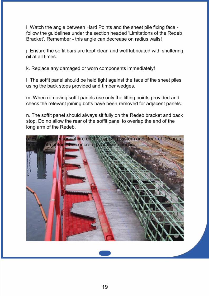
i. Watch the angle between Hard Points and the sheet pile xing face -follow the guidelines under the section headed ‘Limitations of the RedebBracket’. Remember - this angle can decrease on radius walls!
j. Ensure the soft bars are kept clean and well lubricated with shutteringoil at all times.
k. Replace any damaged or worn components immediately!
l. The soft panel should be held tight against the face of the sheet pilesusing the back stops provided and timber wedges.
m. When removing soft panels use only the lifting points provided.and
check the relevant joining bolts have been removed for adjacent panels.
n. The soft panel should always sit fully on the Redeb bracket and backstop. Do no allow the rear of the soft panel to overlap the end of thelong arm of the Redeb.
o. Ensure all personnel are off the capping system and clear of the areaunderneath before the concrete pour commences.
8/11/2019 Capping Manual Rsheetpile
http://slidepdf.com/reader/full/capping-manual-rsheetpile 20/54
A D
B
C
E
SWL
310
F
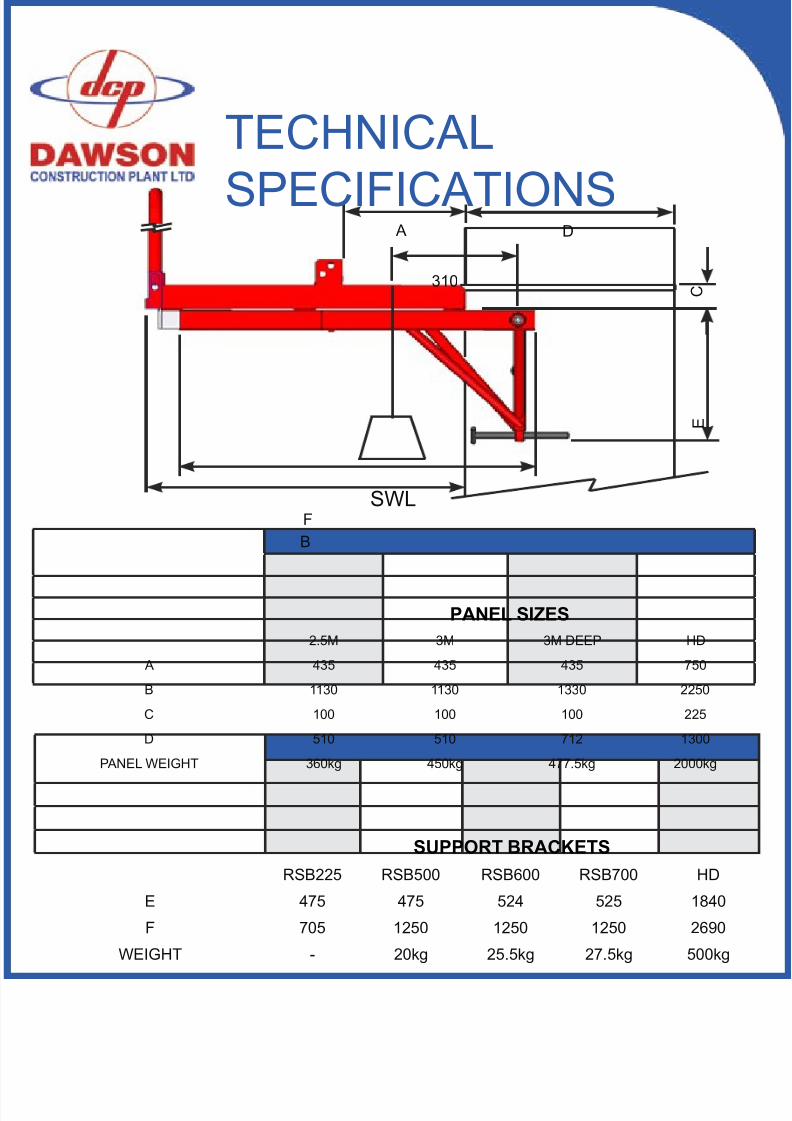
PANEL SIZES2.5M 3M 3M DEEP HD
A 435 435 435 750
B 1130 1130 1330 2250
C 100 100 100 225
D 510 510 712 1300
PANEL WEIGHT 360kg 450kg 477.5kg 2000kg
SUPPORT BRACKETSRSB225 RSB500 RSB600 RSB700 HD
E 475 475 524 525 1840
F 705 1250 1250 1250 2690
WEIGHT - 20kg 25.5kg 27.5kg 500kg
TECHNICAL
SPECIFICATIONS
8/11/2019 Capping Manual Rsheetpile
http://slidepdf.com/reader/full/capping-manual-rsheetpile 21/5421
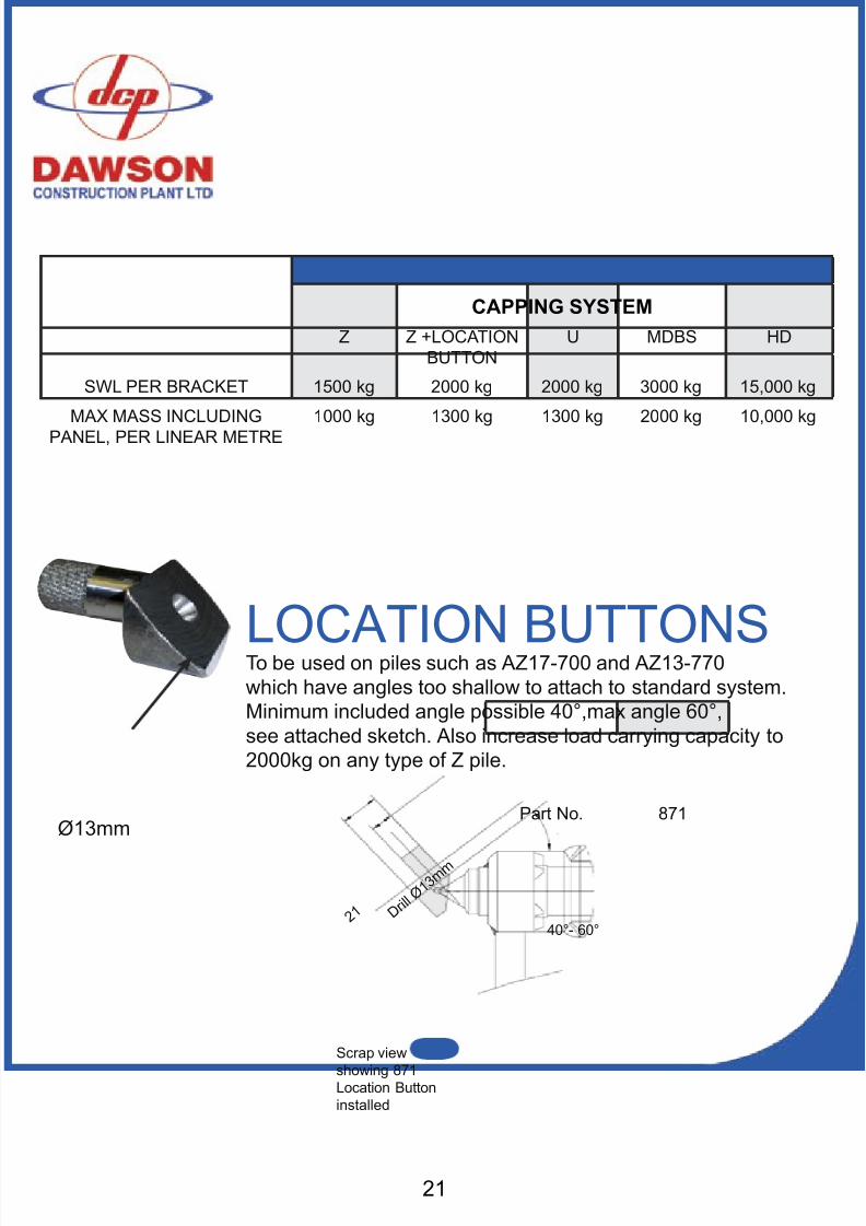
CAPPING SYSTEMZ Z +LOCATION
BUTTONU MDBS HD
SWL PER BRACKET 1500 kg 2000 kg 2000 kg 3000 kg 15,000 kg
MAX MASS INCLUDINGPANEL, PER LINEAR METRE
1000 kg 1300 kg 1300 kg 2000 kg 10,000 kg
Ø13mm
To be used on piles such as AZ17-700 and AZ13-770which have angles too shallow to attach to standard system.Minimum included angle possible 40°,max angle 60°,see attached sketch. Also increase load carrying capacity to2000kg on any type of Z pile.
Scrap view
showing 871Location Buttoninstalled
40°- 60° D r
i l l Ø 1 3
m m
Part No. 871
LOCATION BUTTONS
2 1
8/11/2019 Capping Manual Rsheetpile
http://slidepdf.com/reader/full/capping-manual-rsheetpile 22/54
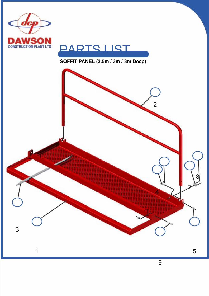
PARTS LISTSOFFIT PANEL (2.5m / 3m / 3m Deep)
1
3
4
5
9
7
8
2
6
8/11/2019 Capping Manual Rsheetpile
http://slidepdf.com/reader/full/capping-manual-rsheetpile 23/5423
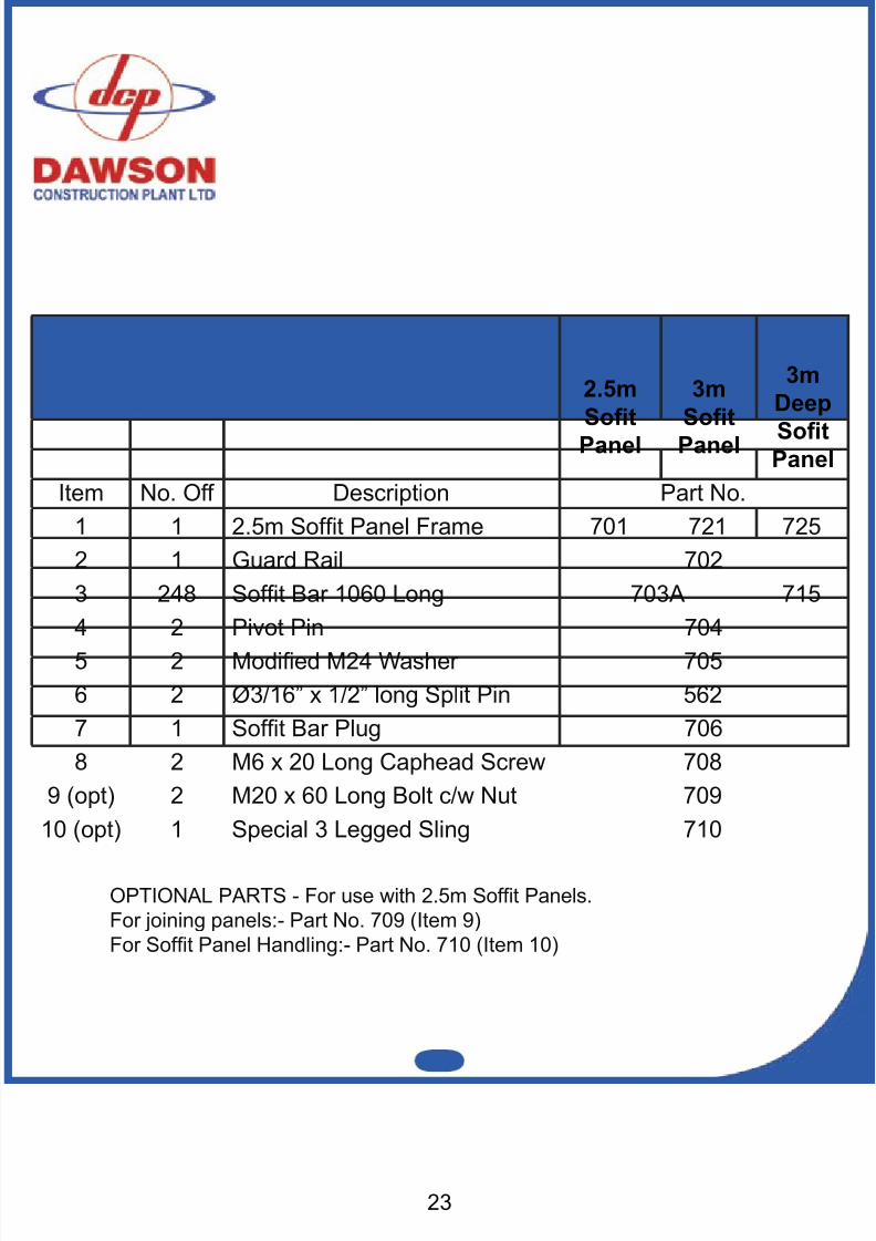
2.5mSotPanel
3mSotPanel
3mDeep
SotPanel
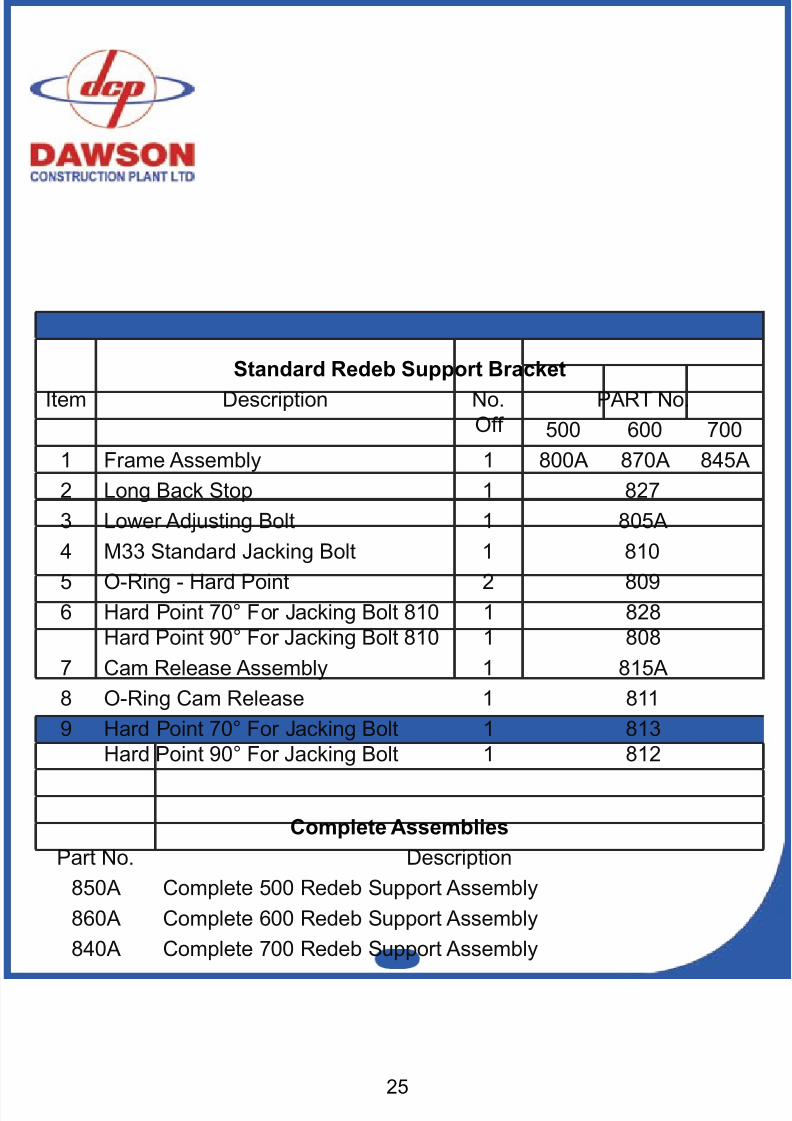
Item No. Off Description Part No.1 1 2.5m Soft Panel Frame 701 721 7252 1 Guard Rail 7023 248 Soft Bar 1060 Long 703A 7154 2 Pivot Pin 7045 2 Modied M24 Washer 7056 2 Ø3/16” x 1/2” long Split Pin 5627 1 Soft Bar Plug 7068 2 M6 x 20 Long Caphead Screw 708
9 (opt) 2 M20 x 60 Long Bolt c/w Nut 70910 (opt) 1 Special 3 Legged Sling 710
OPTIONAL PARTS - For use with 2.5m Soft Panels.For joining panels:- Part No. 709 (Item 9)For Soft Panel Handling:- Part No. 710 (Item 10)
8/11/2019 Capping Manual Rsheetpile
http://slidepdf.com/reader/full/capping-manual-rsheetpile 24/54
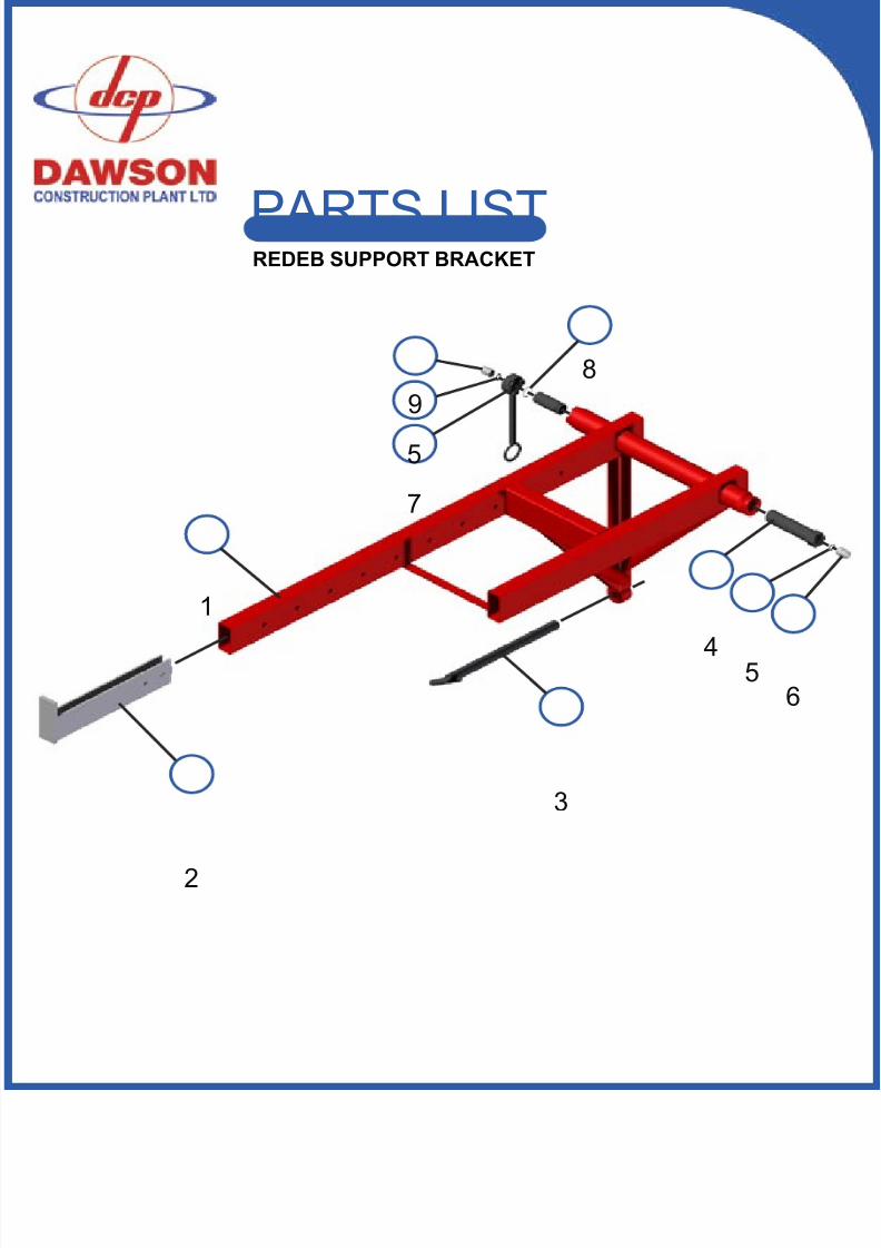
2
1
3
4 56
8
7
5
9
PARTS LISTREDEB SUPPORT BRACKET
8/11/2019 Capping Manual Rsheetpile
http://slidepdf.com/reader/full/capping-manual-rsheetpile 25/54
8/11/2019 Capping Manual Rsheetpile
http://slidepdf.com/reader/full/capping-manual-rsheetpile 26/54
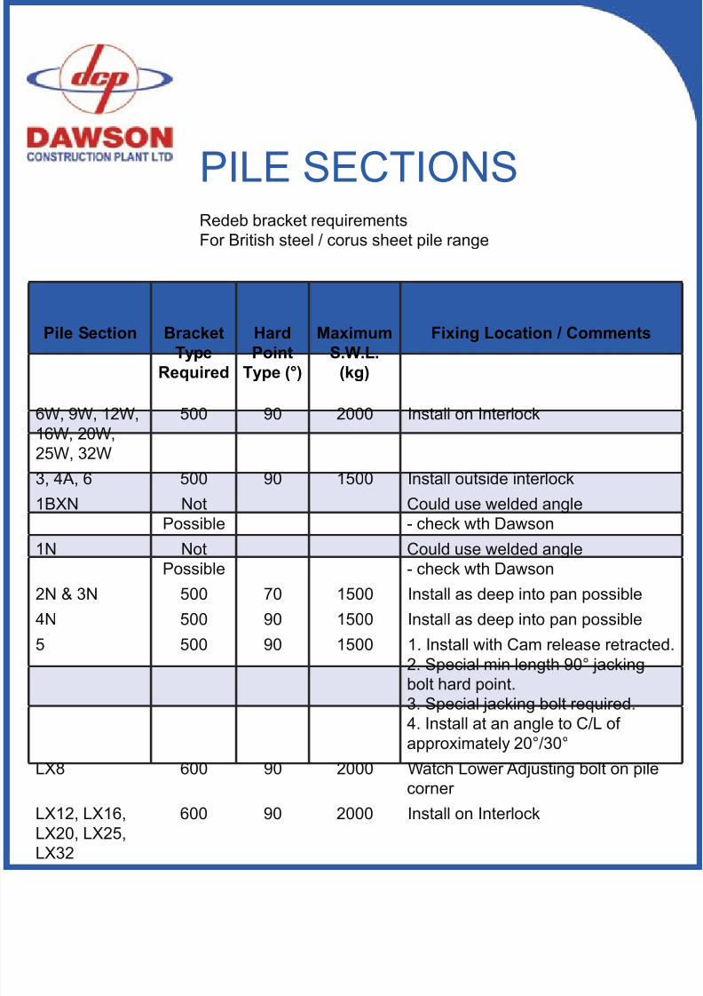
PILE SECTIONS
Pile Section BracketType
Required
HardPoint
Type (°)
MaximumS.W.L.
(kg)
Fixing Location / Comments
6W, 9W, 12W,16W, 20W,25W, 32W
500 90 2000 Install on Interlock
3, 4A, 6 500 90 1500 Install outside interlock1BXN Not
Possible
Could use welded angle
- check wth Dawson1N Not
PossibleCould use welded angle- check wth Dawson
2N & 3N 500 70 1500 Install as deep into pan possible4N 500 90 1500 Install as deep into pan possible5 500 90 1500 1. Install with Cam release retracted.
2. Special min length 90° jackingbolt hard point.3. Special jacking bolt required.4. Install at an angle to C/L ofapproximately 20°/30°
LX8 600 90 2000 Watch Lower Adjusting bolt on pilecorner
LX12, LX16,LX20, LX25,LX32
600 90 2000 Install on Interlock
Redeb bracket requirementsFor British steel / corus sheet pile range
8/11/2019 Capping Manual Rsheetpile
http://slidepdf.com/reader/full/capping-manual-rsheetpile 27/54
Pile Section BracketType
Required
HardPoint
Type (°)
MaximumS.W.L.
(kg)
Fixing Location / Comments
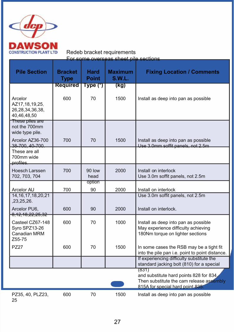
Arcelor AZ17,18,19,25,26,28,34,36,38,
40,46,48,50These piles arenot the 700mmwide type pile.
600 70 1500 Install as deep into pan as possible
Arcelor AZ36-70038-700, 40-700.These are all700mm wideproles.
700 70 1500 Install as deep into pan as possibleUse 3.0mm soft panels, not 2.5m
Hoesch Larssen702, 703, 704
700 90 lowhead
option
2000 Install on interlockUse 3.0m soft panels, not 2.5m
Arcelor AU14,16,17,18,20,21,23,25,26.
700 90 2000 Install on interlockUse 3.0m soft panels, not 2.5m
Arcelor PU6,8,12,18,22,25,32
600 90 2000 Install on interlock.
Casteel CZ67-148Syro SPZ13-26Canadian MRMZ55-75
600 70 1000 Install as deep into pan as possibleMay experience difculty achieving180Nm torque on lighter sections
PZ27 600 70 1500 In some cases the RSB may be a tight tinto the pile pan i.e. point to point distance.If experiencing difculty substitute thestandard jacking bolt (810) for a special(831)and substitute hard points 828 for 834.Then substitute the cam release assembly815A for special hard point 835.
PZ35, 40, PLZ23,25
600 70 1500 Install as deep into pan as possible
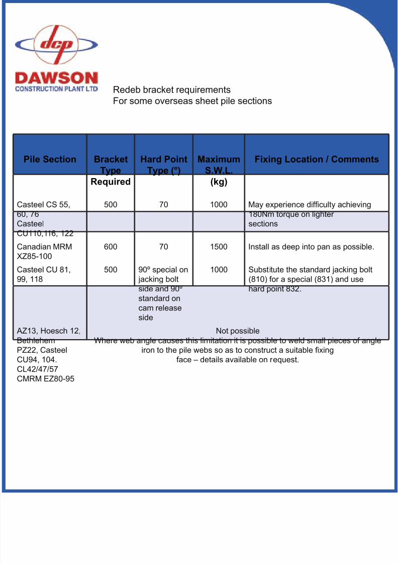
Redeb bracket requirementsFor some overseas sheet pile sections
27
8/11/2019 Capping Manual Rsheetpile
http://slidepdf.com/reader/full/capping-manual-rsheetpile 28/54
Pile Section BracketType
Required
Hard PointType (°)
MaximumS.W.L.
(kg)
Fixing Location / Comments
Casteel CS 55,60, 76CasteelCU110,116, 122
500 70 1000 May experience difculty achieving180Nm torque on lighter sections
Canadian MRMXZ85-100
600 70 1500 Install as deep into pan as possible.
Casteel CU 81,99, 118
500 90º special on jacking boltside and 90ºstandard oncam releaseside
1000 Substitute the standard jacking bolt(810) for a special (831) and usehard point 832.
AZ13, Hoesch 12,BethlehemPZ22, CasteelCU94, 104.CL42/47/57CMRM EZ80-95
Not possibleWhere web angle causes this limitation it is possible to weld small pieces of angle
iron to the pile webs so as to construct a suitable xingface – details available on request.
Redeb bracket requirementsFor some overseas sheet pile sections
8/11/2019 Capping Manual Rsheetpile
http://slidepdf.com/reader/full/capping-manual-rsheetpile 29/54
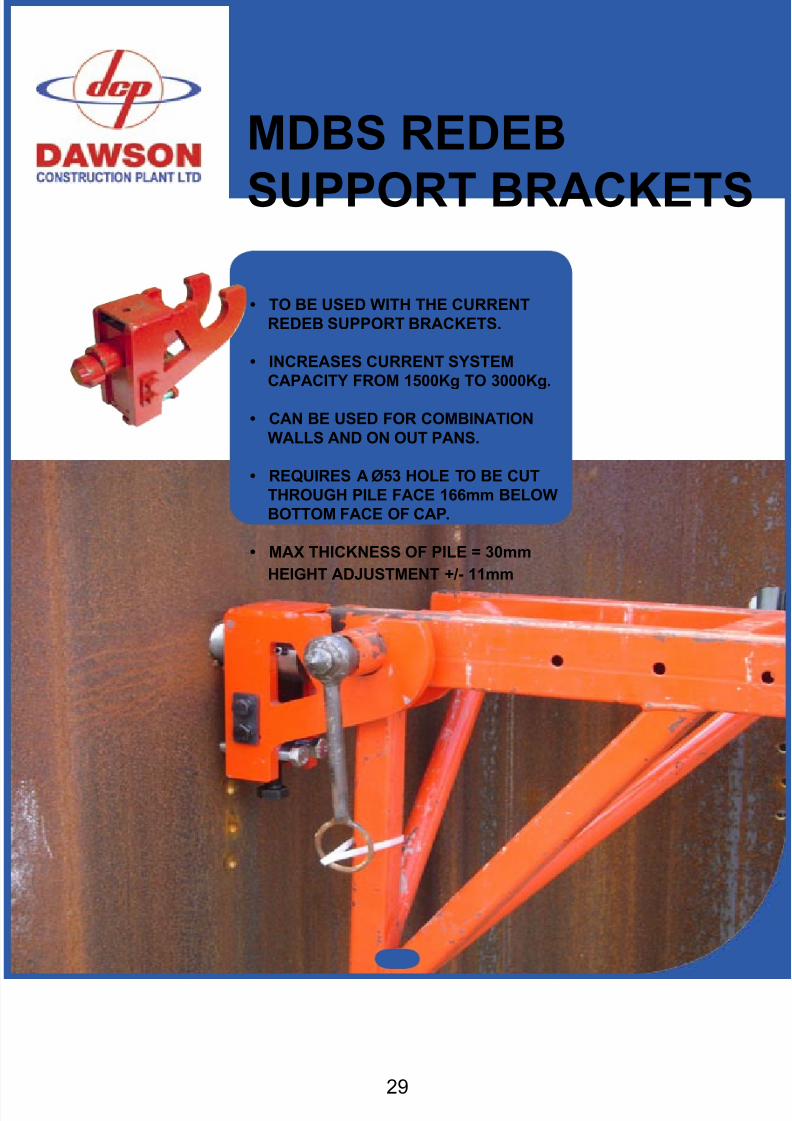
MDBS REDEB
SUPPORT BRACKETS
• TO BE USED WITH THE CURRENTREDEB SUPPORT BRACKETS.
• INCREASES CURRENT SYSTEMCAPACITY FROM 1500Kg TO 3000Kg.
• CAN BE USED FOR COMBINATIONWALLS AND ON OUT PANS.
• REQUIRES A Ø53 HOLE TO BE CUTTHROUGH PILE FACE 166mm BELOWBOTTOM FACE OF CAP.
• MAX THICKNESS OF PILE = 30mm HEIGHT ADJUSTMENT +/- 11mm
29
8/11/2019 Capping Manual Rsheetpile
http://slidepdf.com/reader/full/capping-manual-rsheetpile 30/54
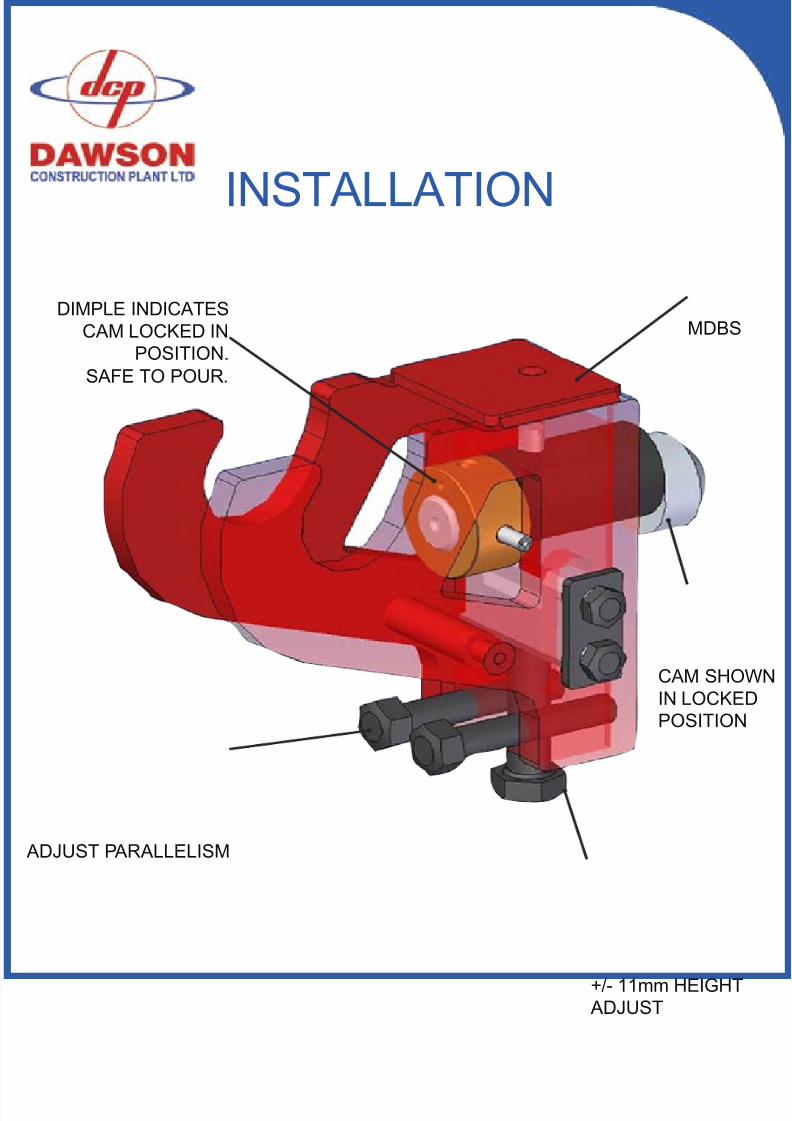
INSTALLATION
DIMPLE INDICATESCAM LOCKED IN
POSITION.SAFE TO POUR .
MDBS
CAM SHOWNIN LOCKEDPOSITION
+/- 11mm HEIGHT ADJUST
ADJUST PARALLELISM
8/11/2019 Capping Manual Rsheetpile
http://slidepdf.com/reader/full/capping-manual-rsheetpile 31/5431
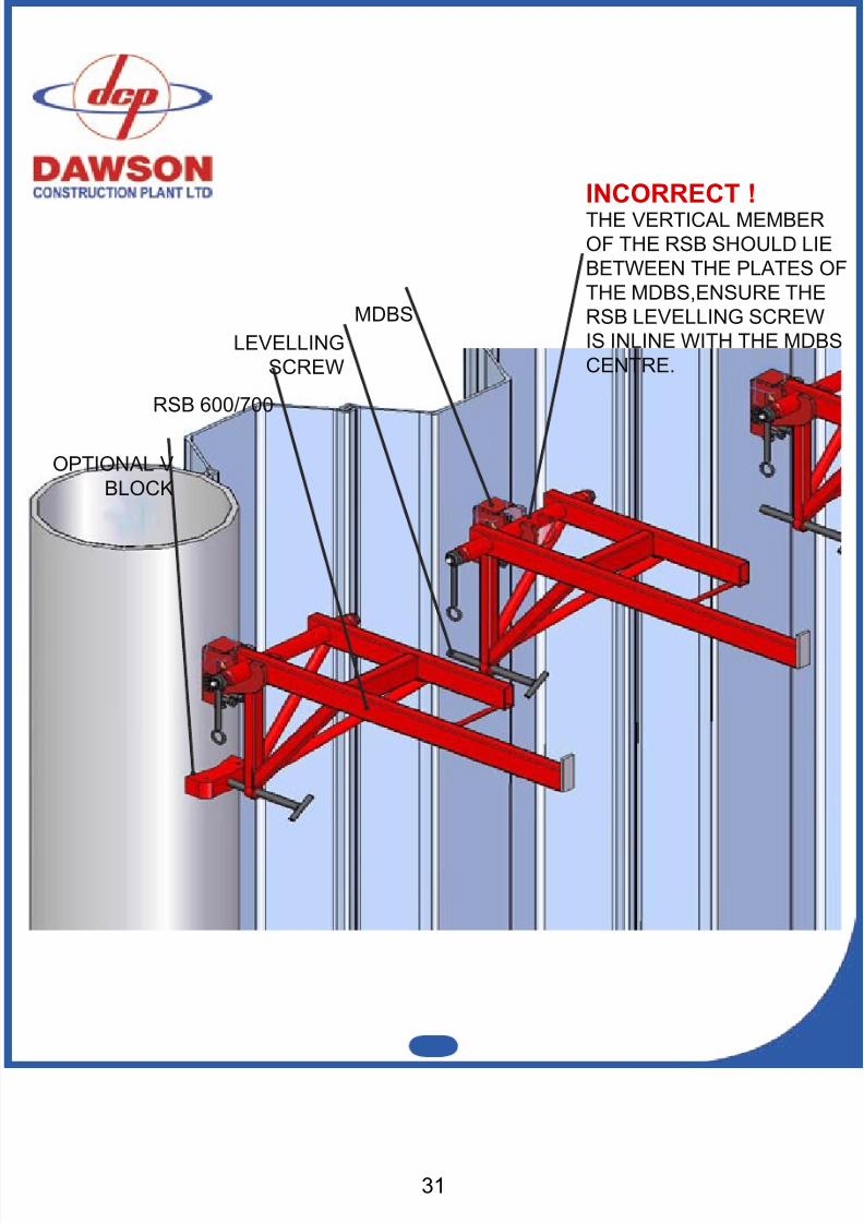
OPTIONAL VBLOCK
RSB 600/700
LEVELLINGSCREW
INCORRECT !THE VERTICAL MEMBEROF THE RSB SHOULD LIEBETWEEN THE PLATES OFTHE MDBS,ENSURE THERSB LEVELLING SCREWIS INLINE WITH THE MDBSCENTRE.
MDBS
8/11/2019 Capping Manual Rsheetpile
http://slidepdf.com/reader/full/capping-manual-rsheetpile 32/54
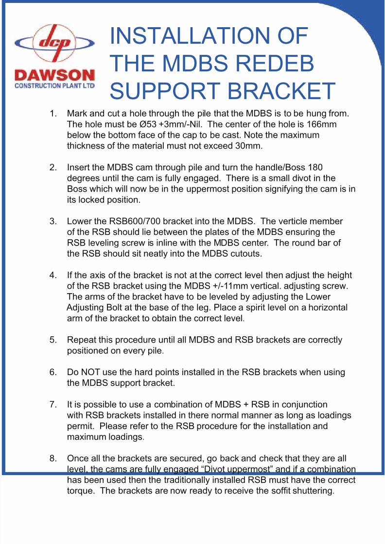
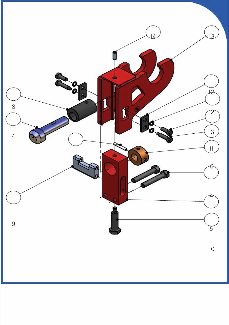
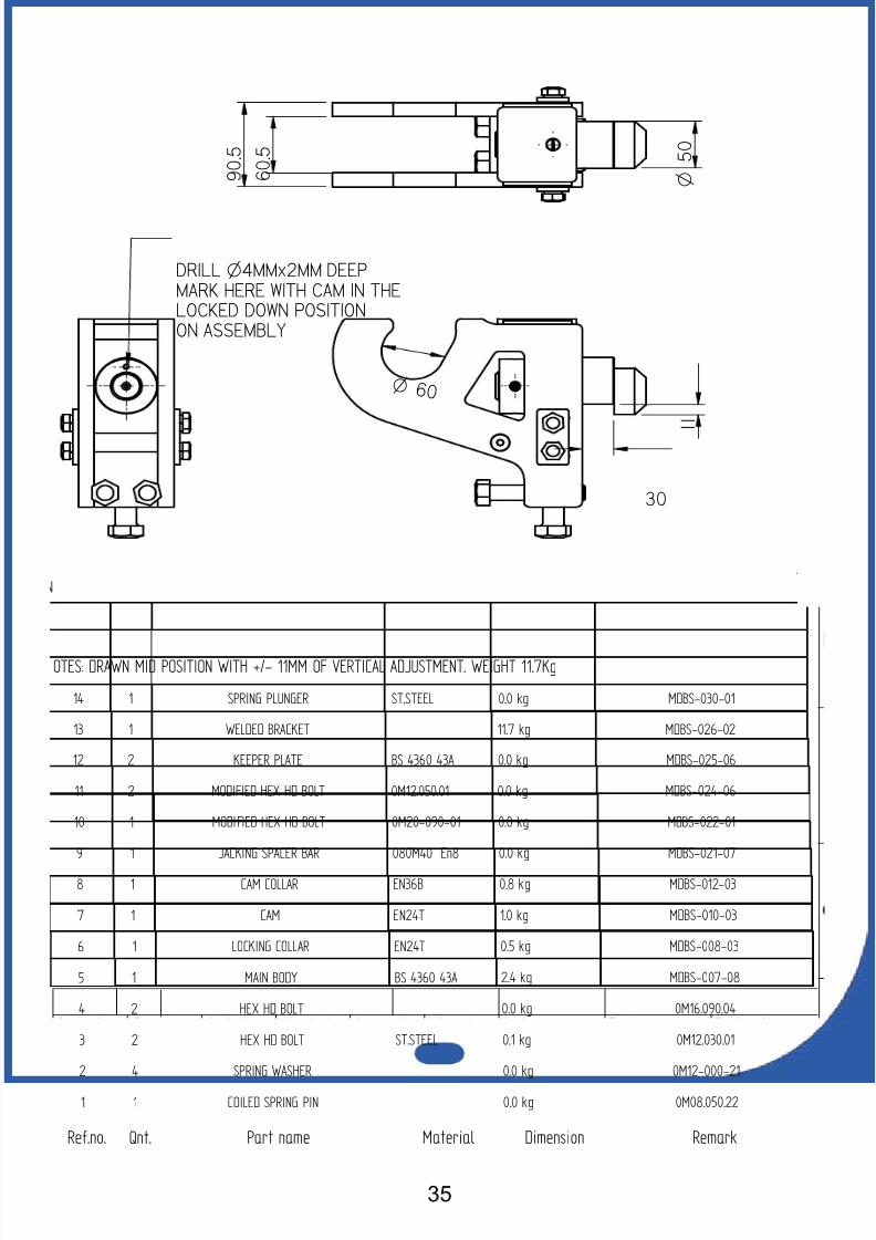
1. Mark and cut a hole through the pile that the MDBS is to be hung from.The hole must be Ø53 +3mm/-Nil. The center of the hole is 166mmbelow the bottom face of the cap to be cast. Note the maximumthickness of the material must not exceed 30mm.
2. Insert the MDBS cam through pile and turn the handle/Boss 180degrees until the cam is fully engaged. There is a small divot in the
Boss which will now be in the uppermost position signifying the cam is inits locked position.
3. Lower the RSB600/700 bracket into the MDBS. The verticle memberof the RSB should lie between the plates of the MDBS ensuring theRSB leveling screw is inline with the MDBS center. The round bar ofthe RSB should sit neatly into the MDBS cutouts.
4. If the axis of the bracket is not at the correct level then adjust the height
of the RSB bracket using the MDBS +/-11mm vertical. adjusting screw.The arms of the bracket have to be leveled by adjusting the Lower
Adjusting Bolt at the base of the leg. Place a spirit level on a horizontalarm of the bracket to obtain the correct level.
5. Repeat this procedure until all MDBS and RSB brackets are correctlypositioned on every pile.
6. Do NOT use the hard points installed in the RSB brackets when usingthe MDBS support bracket.
7. It is possible to use a combination of MDBS + RSB in conjunctionwith RSB brackets installed in there normal manner as long as loadingspermit. Please refer to the RSB procedure for the installation andmaximum loadings.
8. Once all the brackets are secured, go back and check that they are alllevel, the cams are fully engaged “Divot uppermost” and if a combinationhas been used then the traditionally installed RSB must have the correcttorque. The brackets are now ready to receive the soft shuttering.
INSTALLATION OFTHE MDBS REDEB
SUPPORT BRACKET
8/11/2019 Capping Manual Rsheetpile
http://slidepdf.com/reader/full/capping-manual-rsheetpile 33/5433
REMOVAL OF THEMDBS SUPPORT
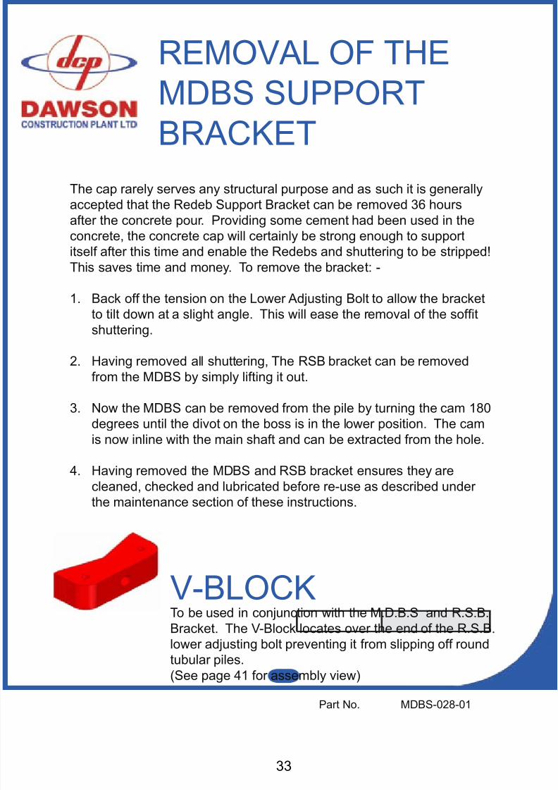
BRACKETThe cap rarely serves any structural purpose and as such it is generallyaccepted that the Redeb Support Bracket can be removed 36 hoursafter the concrete pour. Providing some cement had been used in theconcrete, the concrete cap will certainly be strong enough to supportitself after this time and enable the Redebs and shuttering to be stripped!This saves time and money. To remove the bracket: -
1. Back off the tension on the Lower Adjusting Bolt to allow the bracketto tilt down at a slight angle. This will ease the removal of the softshuttering.
2. Having removed all shuttering, The RSB bracket can be removedfrom the MDBS by simply lifting it out.
3. Now the MDBS can be removed from the pile by turning the cam 180degrees until the divot on the boss is in the lower position. The camis now inline with the main shaft and can be extracted from the hole.
4. Having removed the MDBS and RSB bracket ensures they arecleaned, checked and lubricated before re-use as described underthe maintenance section of these instructions.
V-BLOCKTo be used in conjunction with the M.D.B.S and R.S.B.Bracket. The V-Block locates over the end of the R.S.B.lower adjusting bolt preventing it from slipping off roundtubular piles.(See page 41 for assembly view)
Part No. MDBS-028-01
8/11/2019 Capping Manual Rsheetpile
http://slidepdf.com/reader/full/capping-manual-rsheetpile 34/54
8/11/2019 Capping Manual Rsheetpile
http://slidepdf.com/reader/full/capping-manual-rsheetpile 35/5435

8/11/2019 Capping Manual Rsheetpile
http://slidepdf.com/reader/full/capping-manual-rsheetpile 36/54
NOTES
8/11/2019 Capping Manual Rsheetpile
http://slidepdf.com/reader/full/capping-manual-rsheetpile 37/54
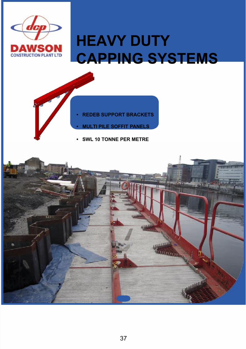
HEAVY DUTY
CAPPING SYSTEMS
37
• REDEB SUPPORT BRACKETS
• MULTI PILE SOFFIT PANELS
• SWL 10 TONNE PER METRE
8/11/2019 Capping Manual Rsheetpile
http://slidepdf.com/reader/full/capping-manual-rsheetpile 38/54
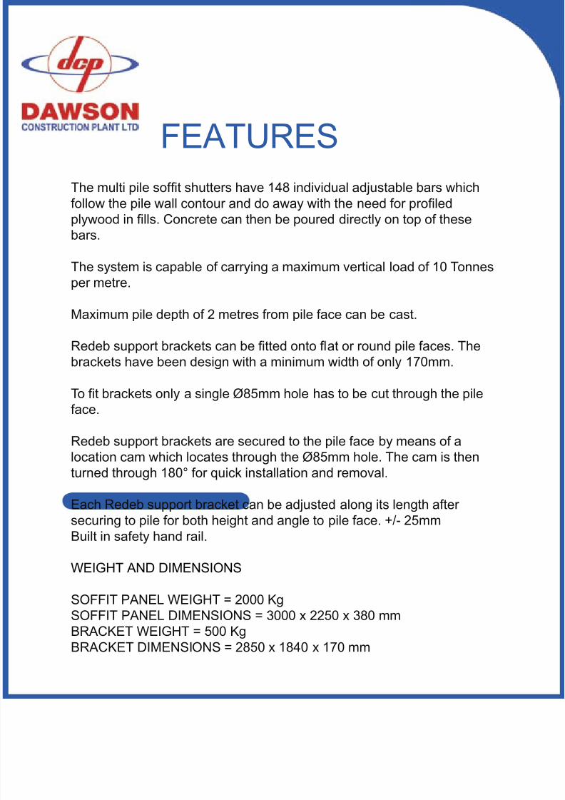
FEATURESThe multi pile soft shutters have 148 individual adjustable bars whichfollow the pile wall contour and do away with the need for proledplywood in lls. Concrete can then be poured directly on top of thesebars.
The system is capable of carrying a maximum vertical load of 10 Tonnesper metre.
Maximum pile depth of 2 metres from pile face can be cast.
Redeb support brackets can be tted onto at or round pile faces. Thebrackets have been design with a minimum width of only 170mm.
To t brackets only a single Ø85mm hole has to be cut through the pileface.
Redeb support brackets are secured to the pile face by means of alocation cam which locates through the Ø85mm hole. The cam is thenturned through 180° for quick installation and removal.
Each Redeb support bracket can be adjusted along its length aftersecuring to pile for both height and angle to pile face. +/- 25mmBuilt in safety hand rail.
WEIGHT AND DIMENSIONS
SOFFIT PANEL WEIGHT = 2000 KgSOFFIT PANEL DIMENSIONS = 3000 x 2250 x 380 mmBRACKET WEIGHT = 500 KgBRACKET DIMENSIONS = 2850 x 1840 x 170 mm
8/11/2019 Capping Manual Rsheetpile
http://slidepdf.com/reader/full/capping-manual-rsheetpile 39/54
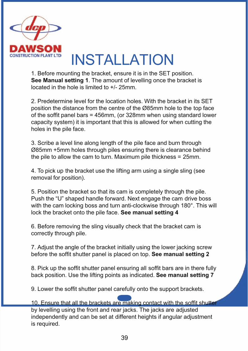
INSTALLATION1. Before mounting the bracket, ensure it is in the SET position.See Manual setting 1 . The amount of levelling once the bracket islocated in the hole is limited to +/- 25mm.
2. Predetermine level for the location holes. With the bracket in its SETposition the distance from the centre of the Ø85mm hole to the top faceof the soft panel bars = 456mm, (or 328mm when using standard lower
capacity system) it is important that this is allowed for when cutting theholes in the pile face.
3. Scribe a level line along length of the pile face and burn throughØ85mm +5mm holes through piles ensuring there is clearance behindthe pile to allow the cam to turn. Maximum pile thickness = 25mm.
4. To pick up the bracket use the lifting arm using a single sling (seeremoval for position).
5. Position the bracket so that its cam is completely through the pile.Push the “U” shaped handle forward. Next engage the cam drive bosswith the cam locking boss and turn anti-clockwise through 180°. This willlock the bracket onto the pile face. See manual setting 4
6. Before removing the sling visually check that the bracket cam iscorrectly through pile.
7. Adjust the angle of the bracket initially using the lower jacking screwbefore the soft shutter panel is placed on top. See manual setting 2
8. Pick up the soft shutter panel ensuring all soft bars are in there fullyback position. Use the lifting points as indicated. See manual setting 7
9. Lower the soft shutter panel carefully onto the support brackets.
10. Ensure that all the brackets are making contact with the soft shutterby levelling using the front and rear jacks. The jacks are adjustedindependently and can be set at different heights if angular adjustmentis required.
39
8/11/2019 Capping Manual Rsheetpile
http://slidepdf.com/reader/full/capping-manual-rsheetpile 40/54
8/11/2019 Capping Manual Rsheetpile
http://slidepdf.com/reader/full/capping-manual-rsheetpile 41/54
REMOVAL OF THE
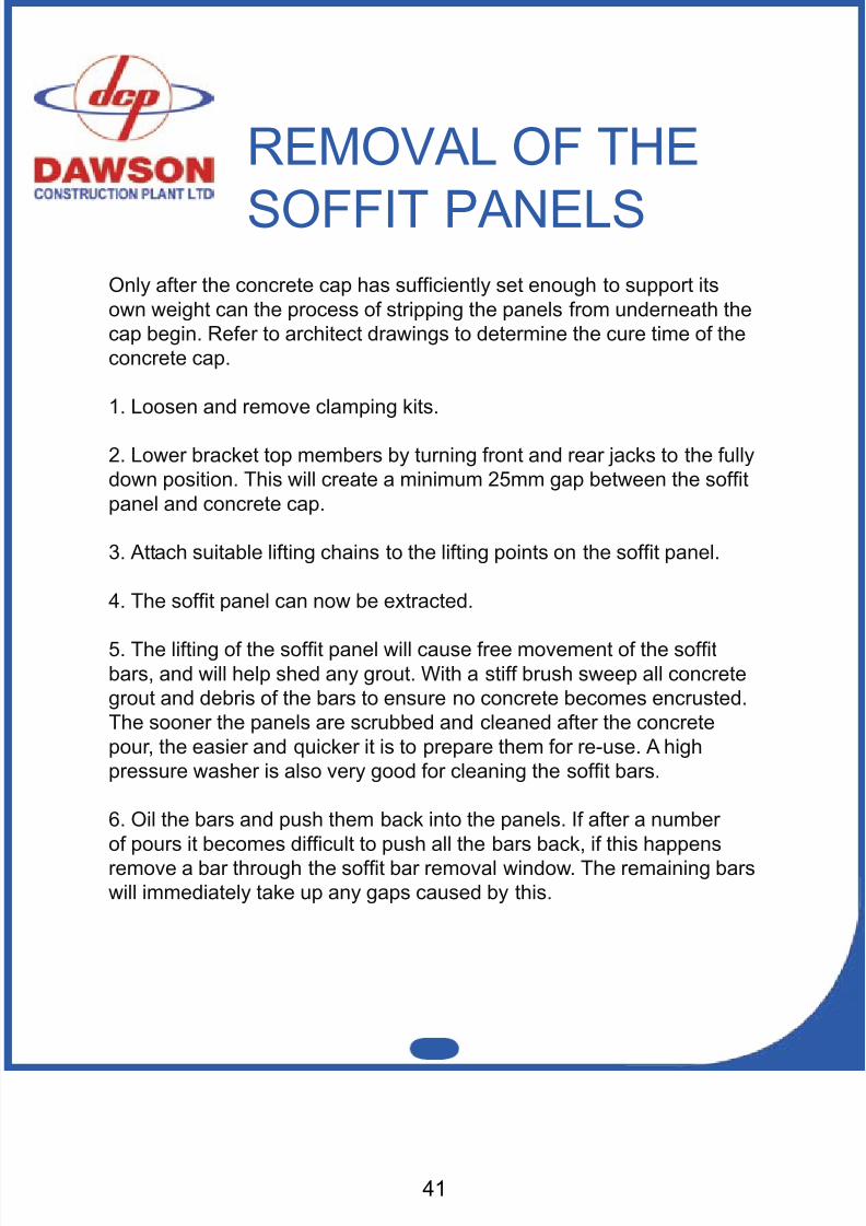
SOFFIT PANELSOnly after the concrete cap has sufciently set enough to support itsown weight can the process of stripping the panels from underneath thecap begin. Refer to architect drawings to determine the cure time of theconcrete cap.
1. Loosen and remove clamping kits.
2. Lower bracket top members by turning front and rear jacks to the fullydown position. This will create a minimum 25mm gap between the softpanel and concrete cap.
3. Attach suitable lifting chains to the lifting points on the soft panel.
4. The soft panel can now be extracted.
5. The lifting of the soft panel will cause free movement of the softbars, and will help shed any grout. With a stiff brush sweep all concretegrout and debris of the bars to ensure no concrete becomes encrusted.The sooner the panels are scrubbed and cleaned after the concretepour, the easier and quicker it is to prepare them for re-use. A highpressure washer is also very good for cleaning the soft bars.
6. Oil the bars and push them back into the panels. If after a numberof pours it becomes difcult to push all the bars back, if this happensremove a bar through the soft bar removal window. The remaining barswill immediately take up any gaps caused by this.
41
8/11/2019 Capping Manual Rsheetpile
http://slidepdf.com/reader/full/capping-manual-rsheetpile 42/54
REMOVAL OF THEREDEB SUPPORT
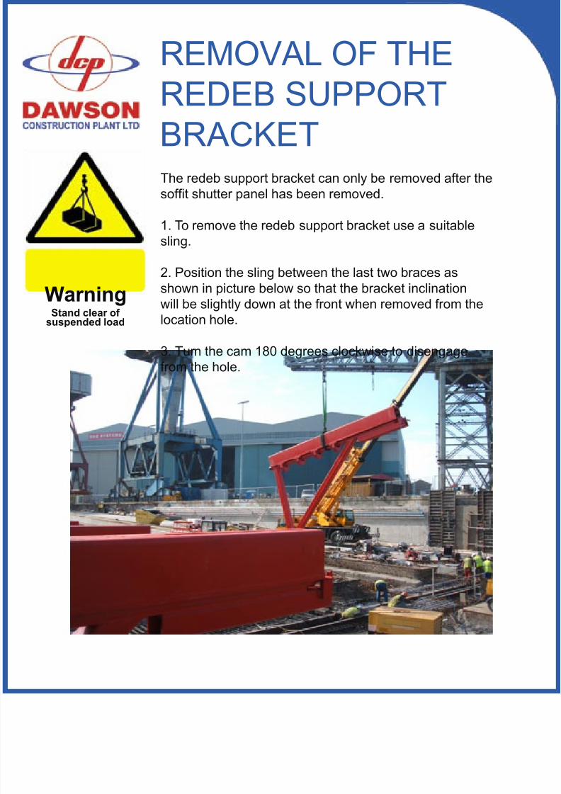
BRACKETThe redeb support bracket can only be removed after thesoft shutter panel has been removed.
1. To remove the redeb support bracket use a suitablesling.
2. Position the sling between the last two braces asshown in picture below so that the bracket inclinationwill be slightly down at the front when removed from thelocation hole.
3. Turn the cam 180 degrees clockwise to disengagefrom the hole.
WarningStand clear of
suspended load
8/11/2019 Capping Manual Rsheetpile
http://slidepdf.com/reader/full/capping-manual-rsheetpile 43/54
8/11/2019 Capping Manual Rsheetpile
http://slidepdf.com/reader/full/capping-manual-rsheetpile 44/54
3 R D A N
G L E
6
5
4
3
2
1
A B C D E
A 3
D A W S O N
C O N S T R U C T I O N
P L A N T L T D
.
I n t r o
.
D a
t e
A p p r .
b y
R e v i s i o n
R f . n r Q n
t .
R e p
l a c e
d b y
D a
t e
R e p
l a c e
F i l e
D r a w
i n g n o .
A f f i r m e
d
S c a
l e
S t a n
d a r d
C h e c k e
d
D r a w n
b y
D e s
i g n
b y
C
o p
i e d
A
1 0
9
B C D
8
7
E F G H
1 0
9
8
7
6
5
4
3
2
F G H
1
R e m a r
k
D i m
e n s i o n
M a
t e r
i a l
P a r
t n a m e
R e
f . n o
.
Q n
t .
-
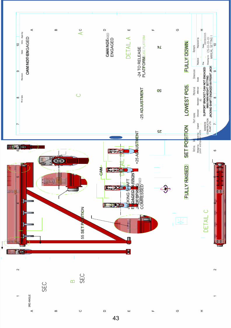
S U P P O R T B R A C K E T F L A T & R O U N D P
I L E
C A M I N E N G A G E D P O S T I O N
J A C K I N G S H A F T E N G A G E D I N R E A R J A C K
p e
t e r w a
t t s p e
t e r w a
t t s
0 8 / 0 9 / 2 0 0 5
C S
- 0 1 - 0 1 - 0 1
M A N U A L S E T T I N G 2
-
-
-
-
-
-
A
D E T A I L A
B
D E T A I L B
C
D E T A I L C
D
D E T A I L D
R O U N D P I L E S E T
- U P
F L A T P I L E S E T
- U P
J A C K I N G
S H A F T E N G A G E D
I N R E A R
J A C K
S P R I N G E X T E N D E D
C A M E N G A G E D
C A M
E N G A G E D
C A M E N G A G E D
2 O F F
L O W E R
J A C K I N G S C R E W S
1 O F F L O
W E R
J A C K I N G S C R E W S
C A M N O T
E N G A G E D
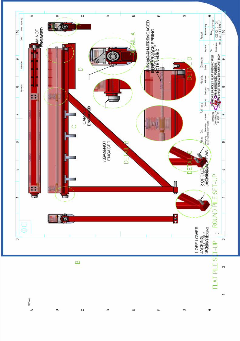
S U P P O R T B R A C K E T F L A T & R O U N D P I L E
C A M I N E N G A G E D P O S I T I O N
J A C K I N G S H A F T E N G A G E D I N F R O N T J A C K
C A M N O T
E N G A G E D
C A M N O T
E N G A G E D
2 O F F L O W E R
J A C K I N G S C R E W S
J A C K I N G S H A F T E N G A G E D
I N R E A R J A C K S P R I N G
E X T E N E D E D
1 O F F L O W E R
J A C K I N G
S C R E W S
8/11/2019 Capping Manual Rsheetpile
http://slidepdf.com/reader/full/capping-manual-rsheetpile 45/5445
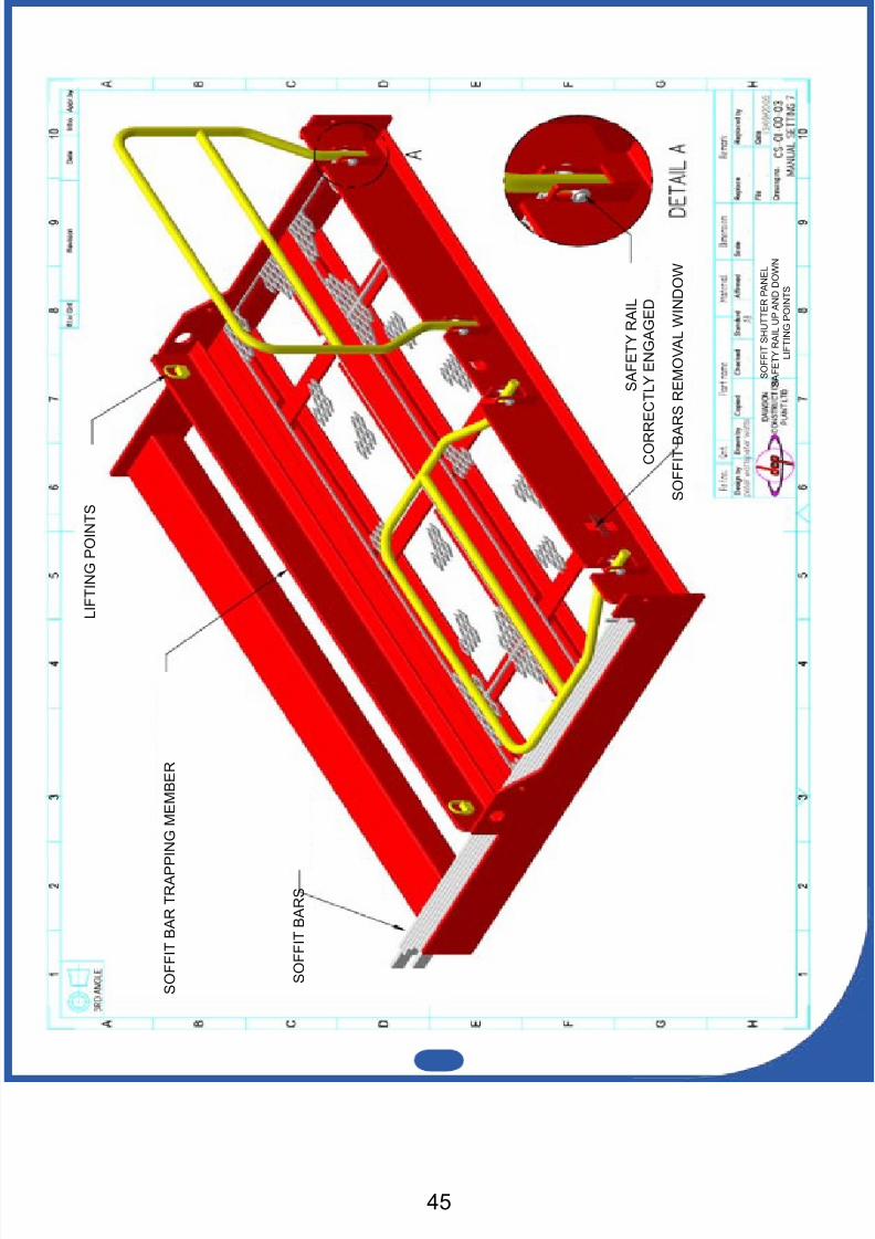
S O F F I T S H U T T E R P A N E L
S A F E T Y R A I L U P A N D D O W N
L I F T I N G P O I N T S
L I F T I N G P O I N T S
S O F F I T B A R T R A P P I N G M E M B E R
S O F F I T B A R S
S O F F I T B A
R S R E M O V A L W I N D O W
S A F E T Y R A I L
C O R R E C T L Y E N G A G E D
8/11/2019 Capping Manual Rsheetpile
http://slidepdf.com/reader/full/capping-manual-rsheetpile 46/54
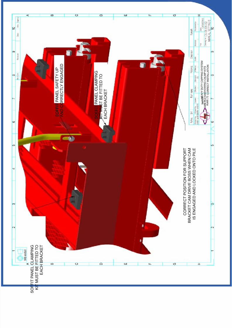
H E A V Y D U T Y C A P P I N G S Y S T E M
S H O W I N G C A L M P K I T S
C O R R E C T I N S T A L L A T I O N
C O R R E C T P O S I T I O N F O R S U P P O R T
B R A C K E T C A M D R I V E B O S S
W H E N C A M
I S E N G A G E D A N D L O C K E D O N T O P I L E
S O F F I T P A N E L C L A M P I N G
K I T M U S T B E F I T T E D T O
E A C H B R A C K E T
S O F F I T P A N E L S A F E T Y U P
A N D C O R R E C T L Y E N G A G E D
S O F F I T P A N E L C L A M P I N G
K I T
M U S T B E F I T T E D T O
E A C H B R A C K E T
8/11/2019 Capping Manual Rsheetpile
http://slidepdf.com/reader/full/capping-manual-rsheetpile 47/5447
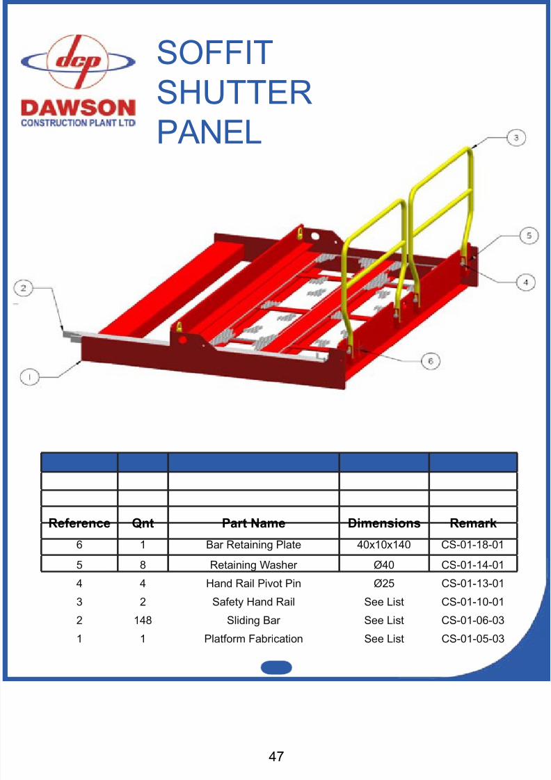
Reference Qnt Part Name Dimensions Remark
6 1 Bar Retaining Plate 40x10x140 CS-01-18-015 8 Retaining Washer Ø40 CS-01-14-01
4 4 Hand Rail Pivot Pin Ø25 CS-01-13-01
3 2 Safety Hand Rail See List CS-01-10-01
2 148 Sliding Bar See List CS-01-06-03
1 1 Platform Fabrication See List CS-01-05-03
SOFFITSHUTTER
PANEL
8/11/2019 Capping Manual Rsheetpile
http://slidepdf.com/reader/full/capping-manual-rsheetpile 48/54
A
DETAIL A
18
4
2,35,2130
1,17
3
343625
28
8
19
27
20
6
22
33
10
2914
24
375
11
9
16
13
7
12
31
26
2315
32
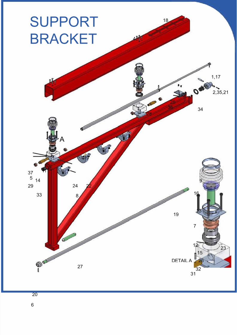
SUPPORTBRACKET
8/11/2019 Capping Manual Rsheetpile
http://slidepdf.com/reader/full/capping-manual-rsheetpile 49/5449
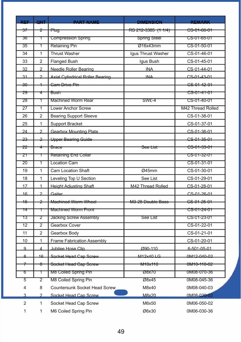
REF QNT PART NAME DIMENSION REMARK
37 2 Plug RS 212-3385 (1 1/4) CS-01-66-01
36 1 Compression Spring Spring Steel CS-01-65-01
35 1 Retaining Pin Ø16x43mm CS-01-50-01
34 1 Thrust Washer Igus Thrust Washer CS-01-46-01
33 2 Flanged Bush Igus Bush CS-01-45-01
32 2 Needle Roller Bearing INA CS-01-44-01
31 2 Axial Cylindrical Roller Bearing INA CS-01-43-01
30 1 Cam Drive Pin CS-01-42-01
29 4 Bush CS-01-41-01
28 1 Machined Worm Rear SW£-4 CS-01-40-01
27 1 Lower Anchor Screw M42 Thread Rolled
26 2 Bearing Support Sleeve CS-01-38-01
25 1 Support Bracket CS-01-37-01
24 2 Gearbox Mounting Plate CS-01-36-01
23 2 Upper Bearing Guide CS-01-35-01
22 4 Brace See List CS-01-33-01
21 1 Retaining End Collar CS-01-32-01
20 1 Location Cam CS-01-31-01
19 1 Cam Location Shaft Ø45mm CS-01-30-01
18 1 Leveling Top U Section See List CS-01-29-0117 1 Height Adjusting Shaft M42 Thread Rolled CS-01-28-01
16 2 Gaiter CS-01-26-01
15 2 Machined Worm Wheel M3-25 Double Boss CS-01-25-01
14 1 Machined Worm Front CS-01-24-01
13 2 Jacking Screw Assembly See List CS-01-23-01
12 2 Gearbox Cover CS-01-22-01
11 2 Gearbox Body CS-01-21-01
10 1 Frame Fabrication Assembly CS-01-20-01
9 4 Jubilee Hose Clip Ø90-110 6-501-05-01
8 16 Socket Head Cap Screw M12x40 LG 0M12-040-02
7 8 Socket Head Cap Screw M10x110 0M10-110-02
6 1 M8 Coiled Spring Pin Ø8x70 0M08-070-36
5 2 M8 Coiled Spring Pin Ø8x45 0M08-045-36
4 8 Countersunk Socket Head Screw M8x40 0M08-040-03
3 2 Socket Head Cap Screw M8x20 0M08-020-02
2 1 Socket Head Cap Screw M6x50 0M06-050-02
1 1 M6 Coiled Spring Pin Ø6x30 0M06-030-36
8/11/2019 Capping Manual Rsheetpile
http://slidepdf.com/reader/full/capping-manual-rsheetpile 50/54
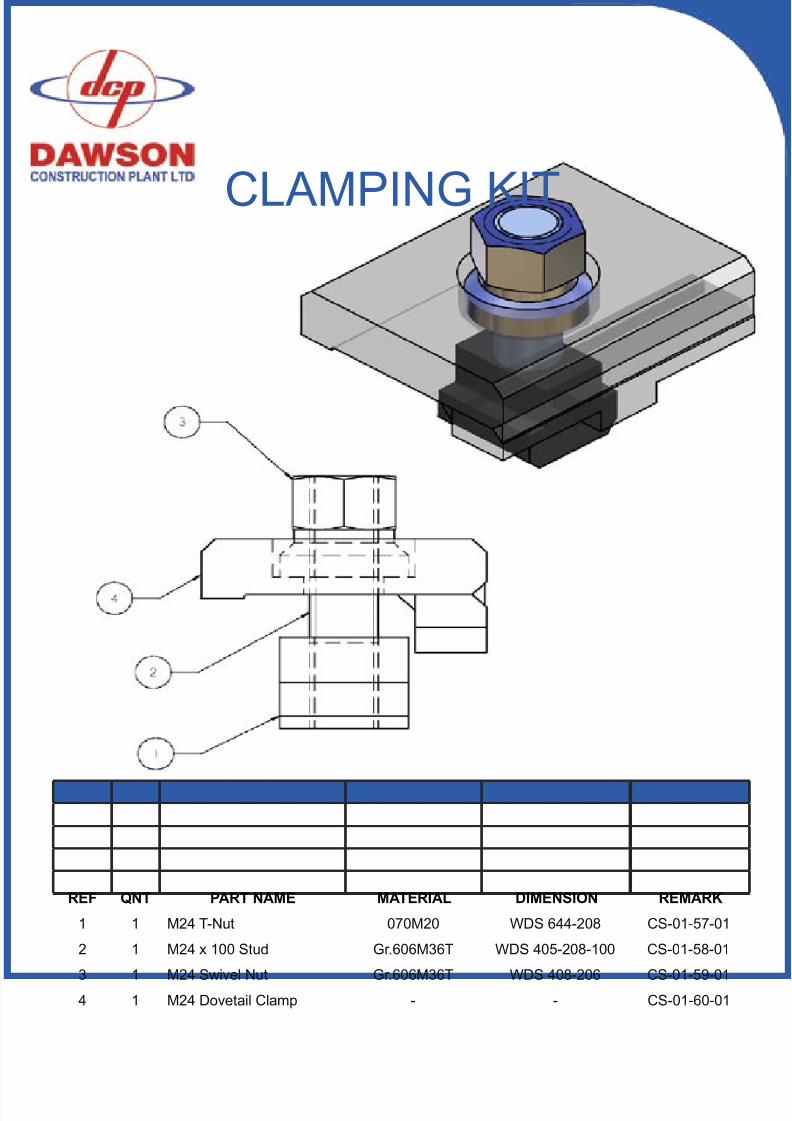
REF QNT PART NAME MATERIAL DIMENSION REMARK
1 1 M24 T-Nut 070M20 WDS 644-208 CS-01-57-01
2 1 M24 x 100 Stud Gr.606M36T WDS 405-208-100 CS-01-58-01
3 1 M24 Swivel Nut Gr.606M36T WDS 408-206 CS-01-59-014 1 M24 Dovetail Clamp - - CS-01-60-01
CLAMPING KIT

8/11/2019 Capping Manual Rsheetpile
http://slidepdf.com/reader/full/capping-manual-rsheetpile 51/5451
NOTES
8/11/2019 Capping Manual Rsheetpile
http://slidepdf.com/reader/full/capping-manual-rsheetpile 52/54
8/11/2019 Capping Manual Rsheetpile
http://slidepdf.com/reader/full/capping-manual-rsheetpile 53/5453

8/11/2019 Capping Manual Rsheetpile
http://slidepdf.com/reader/full/capping-manual-rsheetpile 54/54
Dawson Construction Plant LtdChesney Wold.Bleak Hall,Milton Keynes,MK6 1NE, EnglandTel: +44 (0) 1908 240300
SHEET PILE
CAPPING SYSTEMS