Embed Size (px)
Citation preview
CAPL Callback Interface in CANoe Version 1.3
2017-04-11
Application Note AN-IND-1-012
Author Vector Informatik GmbH
Restrictions Public Document
Abstract Information and explanation on the CAPL Callback Interface (CCI) for diagnostics in CANoe, including examples and references
Table of Contents
1.0 Overview ........................................................................................................................................ 2 2.0 Background ................................................................................................................................... 2
2.1 What is the CCI? .................................................................................................................. 2 2.2 Why use the CCI? ................................................................................................................ 2 2.3 Alternatives to using the CCI ............................................................................................... 2 2.4 What can you do with the CCI? ........................................................................................... 3
3.0 Basic concept of the CAPL callback interface for diagnostics ................................................ 3 3.1 CAPL functions called by the CCI ........................................................................................ 3 3.2 CCI functions called by CAPL .............................................................................................. 3 3.3 Additional configuration steps necessary ............................................................................ 4 3.4 Configuration parameters provided by CANoe .................................................................... 4 3.5 Walkthrough: Basic CCI for ISO TP on CAN ....................................................................... 5 3.5.1 Tester side ........................................................................................................................... 5 3.5.2 ECU simulation side ............................................................................................................. 6
4.0 Concrete implementations for several bus types and protocols ............................................. 6 4.1 Example how to use the CCI include files in an ECU simulation ......................................... 6 4.2 Example how to use the CCI include files in a Test Module ................................................ 9 4.3 Additional hints when using the LIN CCI ...........................................................................10 4.4 Additional hints when using VW TP 2.0 on CAN ...............................................................10
5.0 Additional functionality (independent of bus type) .................................................................11 5.1 Session management ........................................................................................................11 5.2 Simulate special ECU response timing behavior ...............................................................11
6.0 Advanced feature: Fault injection .............................................................................................12 6.1 Background ........................................................................................................................12 6.2 Fault injection without the need to use the CCI .................................................................12 6.3 Example using OSEK_TP.DLL ..........................................................................................13 6.3.1 Basic concept and more information..................................................................................13 6.3.2 Dropping a TP frame ..........................................................................................................13
7.0 Additional Resources .................................................................................................................14 8.0 Contacts .......................................................................................................................................14
CAPL Callback Interface in CANoe
Copyright © 2017 - Vector Informatik GmbH 2 Contact Information: www.vector.com or +49-711-80 670-0
1.0 Overview
This document explains the background and usage of the “CAPL callback interface for diagnostics” (CCI, first introduced in CANoe 5.1), for CANoe 8.5 and later versions. It will assist a developer in deciding whether using the CCI is the right choice, and help implement it in that case.
2.0 Background
This section gives high-level answers the following questions:
> What is the CCI? > Why use it? > What are the alternatives? > What can you do with it?
2.1 What is the CCI?
The CCI is a completely generic way to connect the diagnostics layer of a CAPL program with the transport layer: A separate set of CAPL functions is used to forward diagnostics data to the network, receive data from the network and process it as diagnostics data.
Once a diagnostics description database is configured to be used either by a tester node or a simulation node, the CCI for diagnostics becomes available in the respective CAPL programs. Diagnostics descriptions can be either Basic Diagnostic Descriptions, CANdela “.cdd” files, ODX databases - typically provided as “.pdx” archives – or “.mdx”-Files.
The CCI has a very small interface, which requires the implementation of only a few CAPL functions for ECU simulations and diagnostics testers.
2.2 Why use the CCI?
CANoe provides standard channels for diagnostic communication with ECUs as a diagnostics tester (since CANoe 5.2) and ECU simulation (since CANoe 10.0). These built-in channels are supported on
> CAN (ISO TP/VW TP2.0) > LIN > K-Line > FlexRay (several TP standards) and > DoIP/HSFZ.
They handle the transfer and reception of diagnostic requests and responses on the network. In the CAPL code the developer can completely focus on the application itself e.g. define a request, modify its symbolical parameters as defined in the diagnostic database and send the request.
In some use cases though using the CCI is recommended:
> Advanced simulation of a diagnostics ECU in a CAPL program (use case “test the tester”). > Using a transport protocol (version) that is not yet supported directly in CANoe. > Changing protocol parameters and behavior in a way not supported by standard CANoe means. > Perform violations of the diagnostics protocol in order to implement special tests of the diagnostics
functionality of an ECU.
2.3 Alternatives to using the CCI
For most use cases, it is not necessary to implement the CCI in a diagnostics tester or ECU simulation.
Note If the callback functions are not present in the tester CAPL code, CANoe will automatically use the built-in diagnostics communication channel.
CAPL Callback Interface in CANoe
Copyright © 2017 - Vector Informatik GmbH 3 Contact Information: www.vector.com or +49-711-80 670-0
In some cases it is possible to use a gateway or proxy on a supported bus technology (e.g. CAN) with a supported transport protocol (e.g. ISO TP). All CANoe features are available in this case, only the gateway or proxy has to forward the data to and from the ECU. You may want to read the application note AN-IND-1-004 “Diagnostics via Gateway in CANoe”, which lists different concepts of implementing such gateway nodes. This use case of CANoe is also of special interest for users who need a diagnostic gateway e.g. in early development stages where the gateway hardware to access the ECU is not readily available to developers or testers.
Finally in rare cases it may be more efficient to implement the communication on transport protocol level directly, especially if no (standard) diagnostics description can be used.
2.4 What can you do with the CCI?
The following is a list of tasks possible once the CCI is implemented:
> Change CAN identifiers to test if the ECU only responds to the IDs it was assigned to. > Delay response messages from an ECU simulation for an arbitrary amount of time to test the
timeout implementation in a tester. > Delay transport protocol messages individually to check the transport protocol implementation in
the ECU for correct handling of timeouts. > Change the content of individual transport protocol messages, like padding byte values. > Make the tester or ECU simulation send transport protocol messages which do not conform to the
specification and should cause some error reaction in the receiver. > Any use-case specific non-standard handling that needs direct access to the transport protocol
layer, and non-standard changes to the diagnostics protocol.
3.0 Basic concept of the CAPL callback interface for diagnostics
The CCI works as glue between the diagnostics and transport protocol layers: Whenever a diagnostics object (diagRequest or diagResponse) is sent by the CAPL program, its data is forwarded to the transport protocol, which transfers it on the bus. In addition there are CAPL functions that control the setup and status of the communication connections, and functions that provide information to the CCI.
3.1 CAPL functions called by the CCI
The following CAPL functions are called by the CCI when specific events occur. The functions are denoted by a underscore “_” at the start of the function name. The CAPL program has to perform actions that depend on the concrete transport protocol or use case.
> void _Diag_SetChannelParameters()
The CAPL program is instructed to configure a communications channel to the peer (in a tester node to the ECU, and vice versa). The transport protocol parameters are typically retrieved from CANoe or hard-coded values might be used as well. In a tester, this function is called every time DiagSetTarget is called, in an ECU simulation it is called during measurement start.
> void _Diag_DataRequest (BYTE data[], DWORD count, long furtherSegments);
The provided data has to be sent to the peer. If the argument furtherSegments is non-zero, the data is segmented and may be sent in a special way. Please refer to section 4.4 for details.
> void _Diag_SetupChannelReq();
Called only in a tester before the first request is sent to indicate that a communications channel to the ECU should be established. Connection-oriented protocols need to perform a “channel setup” step, while for most connection-less protocols (like ISO/OSEK TP), nothing has to be done. In latter case it suffices to call Diag_SetupChannelCon() immediately.
> void _Diag_SendFunctional();
Called only in a tester, when a functional request is sent (by the CAPL function DiagSendFunctional).
3.2 CCI functions called by CAPL
The following functions are implemented by CANoe and can be called from the CAPL code. Note the
prefix Diag_ differentiating the functions from other diagnostics related CAPL functions.
CAPL Callback Interface in CANoe
Copyright © 2017 - Vector Informatik GmbH 4 Contact Information: www.vector.com or +49-711-80 670-0
> long Diag_ClosedChannelInd ();
This function communicates to CANoe that the communication channel is no longer available, e.g. the tester closed the channel or a non-reparable error occurred. The CAPL program has to call Diag_SetupChannelCon before further data can be sent.
> void Diag_DataCon (long count);
Tells the diagnostic layer that the given number of bytes of data were transmitted successfully.
> void Diag_DataInd (byte rxBuffer[], long count, long sender);
The given amount of data was received from the peer.
> void Diag_ErrorInd( long error);
Forwards errors to the diagnostics layer, e.g. to stop a function waiting for a diagnostics response.
> void Diag_FirstFrameInd( long source, long dest, long totalLength);
The peer has started to send data of given total length. In a tester node the timer waiting for a reaction from the ECU can be stopped. In an ECU simulation the session timer can be stopped.
> long Diag_SetDataSegmentation( long mode, DWORD maxSegmentSize,
DWORD segmentSeparationTime);
Configure the handling of diagnostics data segmentation. Almost no protocol uses segmentation; therefore it is deactivated per default. Please refer to section 4.4 for details.
> long Diag_SetupChannelCon();
The tester has established a connection to the ECU successfully, or it is not necessary to open a connection at all. This function is not needed in an ECU simulation.
3.3 Additional configuration steps necessary
The following configuration steps have to be performed to allow the CCI to take configuration parameters from the settings of a specific diagnostics description.
> “Configuration | Diagnostics/ISO TP…”: Configure the diagnostics description that should be used in the tester or simulation node. The setting for “Usage of the diagnostics description” must not be “Interpretation only”. For all other settings, the CCI is available; for an ECU simulation the simulation node has to be assigned here. Alternatively, an ECU simulation node can call the CAPL function DiagInitEcuSimulation in its 'on prestart' handler.
> Simulation node “Configuration…” dialog: On page “Modules”, the respective transport protocol nodelayer DLL has to be configured. It is also possible to specify this DLL in a DBC file of a network via the attribute NodeLayerModules e.g. entering osek_tp.dll there.
3.4 Configuration parameters provided by CANoe
With the CCI functions documented so far, diagnostics communication can be configured by using hard-coded values (i.e. specifying the arguments directly in the CAPL code), or retrieving parameters from other source, e.g. a DBC file. Yet in order to write a CCI implementation that can adapt itself to the communication parameters stored inside the diagnostics descriptions configured in CANoe, the mechanism described below has to be used.
Using a set of string handles, CANoe will provide numeric values depending on the active diagnostics description:
long DiagGetCommParameter (char qualifier[]);
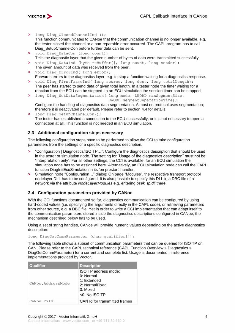
The following table shows a subset of communication parameters that can be queried for ISO TP on CAN. Please refer to the CAPL technical reference (CAPL Function Overview » Diagnostics » DiagGetCommParameter) for a current and complete list. Usage is documented in reference implementations provided by Vector.
Qualifier Description
CANoe.AddressMode
ISO TP address mode: 0: Normal 1: Extended 2: NormalFixed 3: Mixed
<0: No ISO TP
CANoe.TxId CAN Id for transmitted frames
CAPL Callback Interface in CANoe
Copyright © 2017 - Vector Informatik GmbH 5 Contact Information: www.vector.com or +49-711-80 670-0
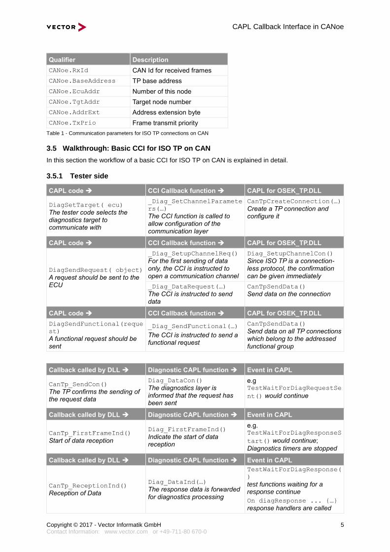
Qualifier Description
CANoe.RxId CAN Id for received frames
CANoe.BaseAddress TP base address
CANoe.EcuAddr Number of this node
CANoe.TgtAddr Target node number
CANoe.AddrExt Address extension byte
CANoe.TxPrio Frame transmit priority
Table 1 - Communication parameters for ISO TP connections on CAN
3.5 Walkthrough: Basic CCI for ISO TP on CAN
In this section the workflow of a basic CCI for ISO TP on CAN is explained in detail.
3.5.1 Tester side
CAPL code CCI Callback function CAPL for OSEK_TP.DLL
DiagSetTarget( ecu)
The tester code selects the diagnostics target to communicate with
_Diag_SetChannelParamete
rs(…)
The CCI function is called to allow configuration of the communication layer
CanTpCreateConnection(…)
Create a TP connection and configure it
CAPL code CCI Callback function CAPL for OSEK_TP.DLL
DiagSendRequest( object)
A request should be sent to the ECU
_Diag_SetupChannelReq()
For the first sending of data only, the CCI is instructed to open a communication channel
Diag_SetupChannelCon()
Since ISO TP is a connection-less protocol, the confirmation can be given immediately
_Diag_DataRequest(…)
The CCI is instructed to send data
CanTpSendData()
Send data on the connection
CAPL code CCI Callback function CAPL for OSEK_TP.DLL
DiagSendFunctional(reque
st)
A functional request should be sent
_Diag_SendFunctional(…)
The CCI is instructed to send a functional request
CanTpSendData()
Send data on all TP connections which belong to the addressed functional group
Callback called by DLL Diagnostic CAPL function Event in CAPL
CanTp_SendCon()
The TP confirms the sending of the request data
Diag_DataCon()
The diagnostics layer is informed that the request has been sent
e.g TestWaitForDiagRequestSe
nt() would continue
Callback called by DLL Diagnostic CAPL function Event in CAPL
CanTp_FirstFrameInd()
Start of data reception
Diag_FirstFrameInd()
Indicate the start of data reception
e.g. TestWaitForDiagResponseS
tart() would continue;
Diagnostics timers are stopped
Callback called by DLL Diagnostic CAPL function Event in CAPL
CanTp_ReceptionInd()
Reception of Data
Diag_DataInd(…)
The response data is forwarded for diagnostics processing
TestWaitForDiagResponse(
)
test functions waiting for a response continue
On diagResponse ... {…}
response handlers are called
CAPL Callback Interface in CANoe
Copyright © 2017 - Vector Informatik GmbH 6 Contact Information: www.vector.com or +49-711-80 670-0
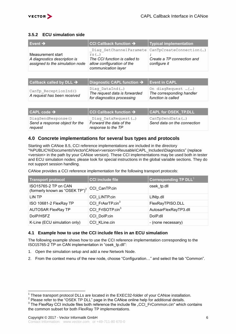
3.5.2 ECU simulation side
Event CCI Callback function Typical implementation
Measurement start A diagnostics description is assigned to the simulation node
_Diag_SetChannelParamete
rs(…)
The CCI function is called to allow configuration of the communication layer
CanTpCreateConnection(…)
;
Create a TP connection and configure it
Callback called by DLL Diagnostic CAPL function Event in CAPL
CanTp_ReceptionInd()
A request has been received
Diag_DataInd(…)
The request data is forwarded for diagnostics processing
On diagRequest …{…}
The corresponding handler function is called
CAPL code CCI Callback function CAPL for OSEK_TP.DLL
DiagSendResponse()
Send a response object for the request
_Diag_DataRequest(…)
Forward the data of the response to the TP
CanTpSendData(…)
Send data on the connection
4.0 Concrete implementations for several bus types and protocols
Starting with CANoe 8.5, CCI reference implementations are included in the directory “%PUBLIC%\Documents\Vector\CANoe\<version>\Reusable\CAPL_Includes\Diagnostics” (replace <version> in the path by your CANoe version). These CCI implementations may be used both in tester and ECU simulation nodes; please look for special instructions in the global variable sections. They do not support session handling.
CANoe provides a CCI reference implementation for the following transport protocols:
Transport protocol CCI include file Corresponding TP DLL1
ISO15765-2 TP on CAN (formerly known as “OSEK TP”)
2
CCI_CanTP.cin osek_tp.dll
LIN TP CCI_LINTP.cin LINtp.dll
ISO 10681-2 FlexRay TP CCI_FrAsrTP.cin3 FlexRayTPISO.DLL
AUTOSAR FlexRay TP CCI_FrISOTP.cin3 AutosarFlexRayTP3.dll
DoIP/HSFZ CCI_DoIP.cin DoIP.dll
K-Line (ECU simulation only) CCI_KLine.cin - (none necessary)
4.1 Example how to use the CCI include files in an ECU simulation
The following example shows how to use the CCI reference implementation corresponding to the ISO15765-2 TP on CAN implementation in “osek_tp.dll”:
1. Open the simulation setup and add a new Network Node.
2. From the context menu of the new node, choose “Configuration…” and select the tab “Common”.
1 These transport protocol DLLs are located in the EXEC32-folder of your CANoe installation.
2 Please refer to the “OSEK TP DLL” page in the CANoe online help for additional details.
3 The FlexRay CCI include files both reference the include file „CCI_FrCommon.cin“ which contains
the common subset for both FlexRay TP implementations.
CAPL Callback Interface in CANoe
Copyright © 2017 - Vector Informatik GmbH 7 Contact Information: www.vector.com or +49-711-80 670-0
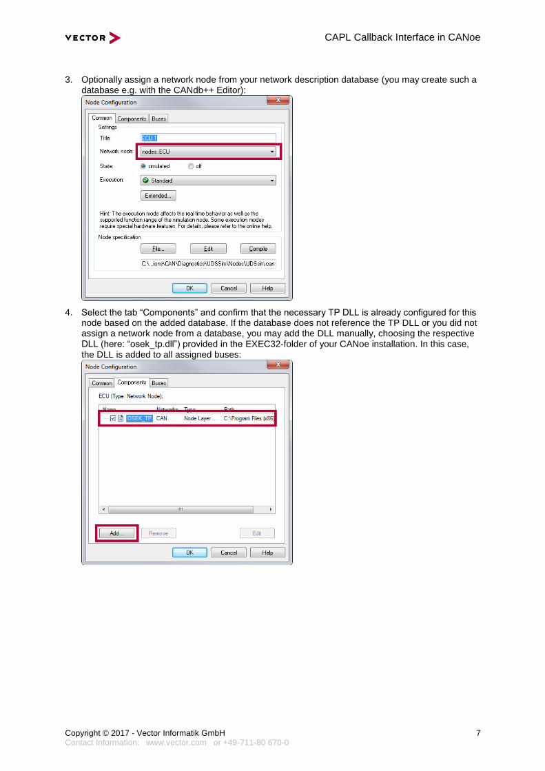
3. Optionally assign a network node from your network description database (you may create such a database e.g. with the CANdb++ Editor):
4. Select the tab “Components” and confirm that the necessary TP DLL is already configured for this node based on the added database. If the database does not reference the TP DLL or you did not assign a network node from a database, you may add the DLL manually, choosing the respective DLL (here: “osek_tp.dll”) provided in the EXEC32-folder of your CANoe installation. In this case, the DLL is added to all assigned buses:
CAPL Callback Interface in CANoe
Copyright © 2017 - Vector Informatik GmbH 8 Contact Information: www.vector.com or +49-711-80 670-0
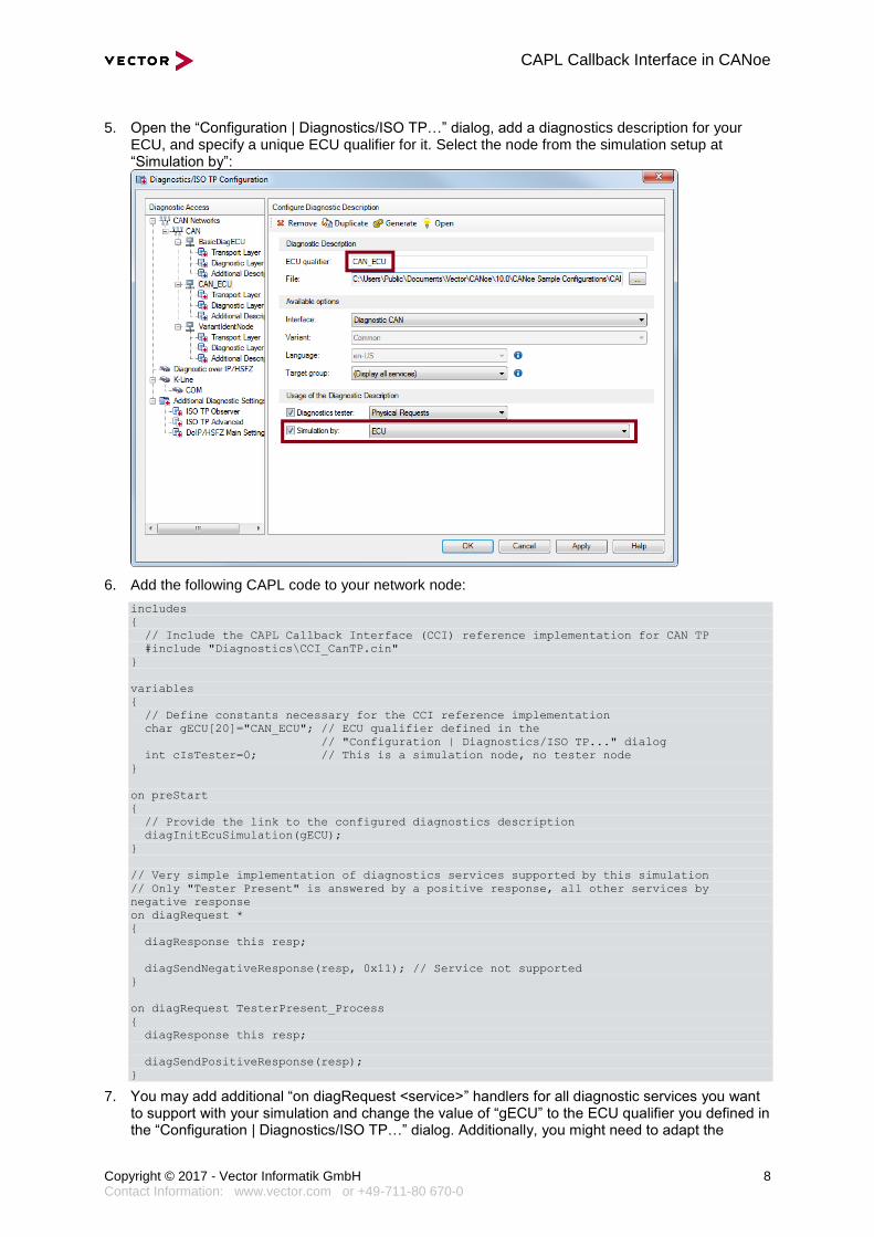
5. Open the “Configuration | Diagnostics/ISO TP…” dialog, add a diagnostics description for your ECU, and specify a unique ECU qualifier for it. Select the node from the simulation setup at “Simulation by”:
6. Add the following CAPL code to your network node:
includes
{
// Include the CAPL Callback Interface (CCI) reference implementation for CAN TP
#include "Diagnostics\CCI_CanTP.cin"
}
variables
{
// Define constants necessary for the CCI reference implementation
char gECU[20]="CAN_ECU"; // ECU qualifier defined in the
// "Configuration | Diagnostics/ISO TP..." dialog
int cIsTester=0; // This is a simulation node, no tester node
}
on preStart
{
// Provide the link to the configured diagnostics description
diagInitEcuSimulation(gECU);
}
// Very simple implementation of diagnostics services supported by this simulation
// Only "Tester Present" is answered by a positive response, all other services by
negative response
on diagRequest *
{
diagResponse this resp;
diagSendNegativeResponse(resp, 0x11); // Service not supported
}
on diagRequest TesterPresent_Process
{
diagResponse this resp;
diagSendPositiveResponse(resp);
}
7. You may add additional “on diagRequest <service>” handlers for all diagnostic services you want to support with your simulation and change the value of “gECU” to the ECU qualifier you defined in the “Configuration | Diagnostics/ISO TP…” dialog. Additionally, you might need to adapt the
CAPL Callback Interface in CANoe
Copyright © 2017 - Vector Informatik GmbH 9 Contact Information: www.vector.com or +49-711-80 670-0
service name for the “Tester Present” service (in this example: “TesterPresent_Process”) to the service identifier specified in your diagnostic description.
4.2 Example how to use the CCI include files in a Test Module
Note You will typically only use the CCI in a Test Module if you need a non-standard tester behavior for whatever reason.
For most use cases, a Test Module will not need to implement a CCI - the CANoe internal diagnostics channel will be sufficient. The difference is that when using the internal diagnostics channel, you do not need to include the *.cin file containing the CCI implementation and also do not need to define the constants “gECU” and “cIsTester”. You only need to set the diagnostic target using “diagSetTarget()”.
1. Open the simulation setup and add a new Test Module.
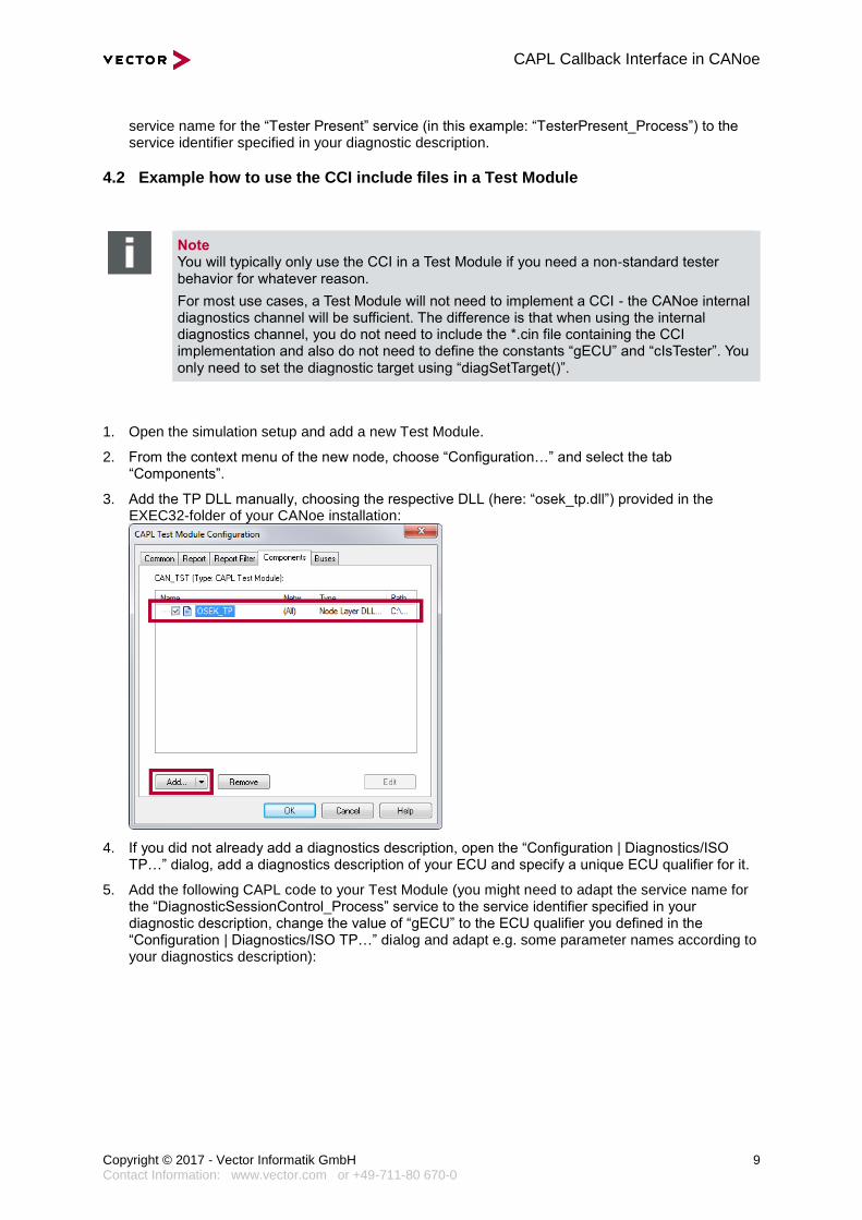
2. From the context menu of the new node, choose “Configuration…” and select the tab “Components”.
3. Add the TP DLL manually, choosing the respective DLL (here: “osek_tp.dll”) provided in the EXEC32-folder of your CANoe installation:
4. If you did not already add a diagnostics description, open the “Configuration | Diagnostics/ISO TP…” dialog, add a diagnostics description of your ECU and specify a unique ECU qualifier for it.
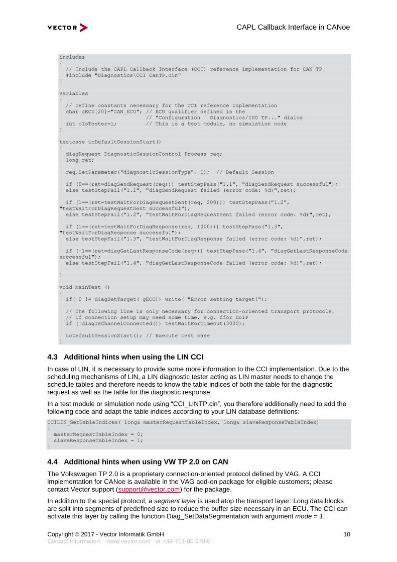
5. Add the following CAPL code to your Test Module (you might need to adapt the service name for the “DiagnosticSessionControl_Process” service to the service identifier specified in your diagnostic description, change the value of “gECU” to the ECU qualifier you defined in the “Configuration | Diagnostics/ISO TP…” dialog and adapt e.g. some parameter names according to your diagnostics description):
CAPL Callback Interface in CANoe
Copyright © 2017 - Vector Informatik GmbH 10 Contact Information: www.vector.com or +49-711-80 670-0
includes
{
// Include the CAPL Callback Interface (CCI) reference implementation for CAN TP
#include "Diagnostics\CCI_CanTP.cin"
}
variables
{
// Define constants necessary for the CCI reference implementation
char gECU[20]="CAN_ECU"; // ECU qualifier defined in the
// "Configuration | Diagnostics/ISO TP..." dialog
int cIsTester=1; // This is a test module, no simulation node
}
testcase tcDefaultSessionStart()
{
diagRequest DiagnosticSessionControl_Process req;
long ret;
req.SetParameter("diagnosticSessionType", 1); // Default Session
if (0==(ret=diagSendRequest(req))) testStepPass("1.1", "diagSendRequest successful");
else testStepFail("1.1", "diagSendRequest failed (error code: %d)",ret);
if (1==(ret=testWaitForDiagRequestSent(req, 200))) testStepPass("1.2",
"testWaitForDiagRequestSent successful");
else testStepFail("1.2", "testWaitForDiagRequestSent failed (error code: %d)",ret);
if (1==(ret=testWaitForDiagResponse(req, 1000))) testStepPass("1.3",
"testWaitForDiagResponse successful");
else testStepFail("1.3", "testWaitForDiagResponse failed (error code: %d)",ret);
if (-1==(ret=diagGetLastResponseCode(req))) testStepPass("1.4", "diagGetLastResponseCode
successful");
else testStepFail("1.4", "diagGetLastResponseCode failed (error code: %d)",ret);
}
void MainTest ()
{
if( 0 != diagSetTarget( gECU)) write( "Error setting target!");
// The following line is only necessary for connection-oriented transport protocols,
// if connection setup may need some time, e.g. ffor DoIP
if (!diagIsChannelConnected()) testWaitForTimeout(3000);
tcDefaultSessionStart(); // Execute test case
}
4.3 Additional hints when using the LIN CCI
In case of LIN, it is necessary to provide some more information to the CCI implementation. Due to the scheduling mechanisms of LIN, a LIN diagnostic tester acting as LIN master needs to change the schedule tables and therefore needs to know the table indices of both the table for the diagnostic request as well as the table for the diagnostic response.
In a test module or simulation node using “CCI_LINTP.cin”, you therefore additionally need to add the following code and adapt the table indices according to your LIN database definitions:
CCILIN_GetTableIndices( long& masterRequestTableIndex, long& slaveResponseTableIndex)
{
masterRequestTableIndex = 0;
slaveResponseTableIndex = 1;
}
4.4 Additional hints when using VW TP 2.0 on CAN
The Volkswagen TP 2.0 is a proprietary connection-oriented protocol defined by VAG. A CCI implementation for CANoe is available in the VAG add-on package for eligible customers; please contact Vector support ([email protected]) for the package.
In addition to the special protocol, a segment layer is used atop the transport layer: Long data blocks are split into segments of predefined size to reduce the buffer size necessary in an ECU. The CCI can activate this layer by calling the function Diag_SetDataSegmentation with argument mode = 1.
CAPL Callback Interface in CANoe
Copyright © 2017 - Vector Informatik GmbH 11 Contact Information: www.vector.com or +49-711-80 670-0
After installation of the add-on package, the VW_TP20.DLL can be found in the Exec32 directory of CANoe. Please refer to the manuals “DiagnosticsInCANoe.pdf” and “VW_TP20_Documentation_eng.pdf” also installed with the add-on package for additional details.
5.0 Additional functionality (independent of bus type)
Often required functionality that is not implemented in the examples of section 4.0 is collected in this section as a basis for further development.
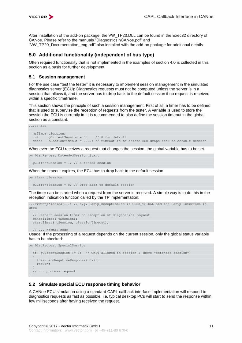
5.1 Session management
For the use case “test the tester” it is necessary to implement session management in the simulated diagnostics server (ECU): Diagnostics requests must not be computed unless the server is in a session that allows it, and the server has to drop back to the default session if no request is received within a specific timeframe.
This section shows the principle of such a session management. First of all, a timer has to be defined that is used to supervise the reception of requests from the tester. A variable is used to store the session the ECU is currently in. It is recommended to also define the session timeout in the global section as a constant.
variables
{
msTimer tSession;
int gCurrentSession = 0; // 0 for default
const cSessionTimeout = 2000; // timeout in ms before ECU drops back to default session
}
Whenever the ECU receives a request that changes the session, the global variable has to be set.
on DiagRequest ExtendedSession_Start
{
gCurrentSession = 1; // Extended session
}
When the timeout expires, the ECU has to drop back to the default session.
on timer tSession
{
gCurrentSession = 0; // Drop back to default session
}
The timer can be started when a request from the server is received. A simple way is to do this in the reception indication function called by the TP implementation:
...TPReceptionInd(...) // e.g. CanTp_ReceptionInd if OSEK_TP.DLL and the CanTp interface is
used
{
// Restart session timer on reception of diagnostics request
cancelTimer( tSession);
startTimer( tSession, cSessionTimeout);
// ... normal code
Usage: If the processing of a request depends on the current session, only the global status variable has to be checked:
on DiagRequest SpecialService
{
if( gCurrentSession != 1) // Only allowed in session 1 (here "extended session")
{
this.SendNegativeResponse( 0x7f);
return;
}
// ... process request
}
5.2 Simulate special ECU response timing behavior
A CANoe ECU simulation using a standard CAPL callback interface implementation will respond to diagnostics requests as fast as possible, i.e. typical desktop PCs will start to send the response within few milliseconds after having received the request.
CAPL Callback Interface in CANoe
Copyright © 2017 - Vector Informatik GmbH 12 Contact Information: www.vector.com or +49-711-80 670-0
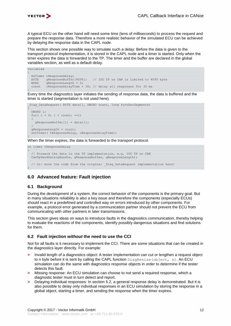
A typical ECU on the other hand will need some time (tens of milliseconds) to process the request and prepare the response data. Therefore a more realistic behavior of the simulated ECU can be achieved by delaying the response data in the CAPL node.
This section shows one possible way to simulate such a delay: Before the data is given to the transport protocol implementation, it is stored in the CAPL node and a timer is started. Only when the timer expires the data is forwarded to the TP. The timer and the buffer are declared in the global variables section, as well as a default delay.
variables
{
msTimer tResponseDelay;
BYTE gResponseBuffer[4095]; // ISO TP on CAN is limited to 4095 byte
WORD gResponseLength = 0;
const cResponseDelayTime = 30; // delay all responses for 30 ms
}
Every time the diagnostics layer initiates the sending of response data, the data is buffered and the timer is started (segmentation is not used here).
_Diag_DataRequest( BYTE data[], DWORD count, long furtherSegments)
{
DWORD i;
for( i = 0; i < count; ++i)
{
gResponseBuffer[i] = data[i];
}
gResponseLength = count;
setTimer( tResponseDelay, cResponseDelayTime);
}
When the timer expires, the data is forwarded to the transport protocol.
on timer tResponseDelay
{
// Forward the data to the TP implementation, e.g. ISO TP on CAN
CanTpSendData(gHandle, gResponseBuffer, gResponseLength);
// Or: move the code from the original _Diag_DataRequest implementation here!
}
6.0 Advanced feature: Fault injection
6.1 Background
During the development of a system, the correct behavior of the components is the primary goal. But in many situations reliability is also a key issue and therefore the components (especially ECUs) should react in a predefined and controlled way on errors introduced by other components. For example, a protocol error generated by a communication partner should not prevent the ECU from communicating with other partners in later transmissions.
This section gives ideas on ways to introduce faults in the diagnostics communication, thereby helping to evaluate the reactions of the components, identify possibly dangerous situations and find solutions for them.
6.2 Fault injection without the need to use the CCI
Not for all faults is it necessary to implement the CCI. There are some situations that can be created in the diagnostics layer directly. For example:
> Invalid length of a diagnostics object: A tester implementation can cut or lengthen a request object
to n byte before it is sent by calling the CAPL function DiagResize(object, n). An ECU
simulation can do the same with diagnostics response objects in order to determine if the tester detects this fault.
> Missing response: An ECU simulation can choose to not send a required response, which a diagnostic tester must in turn detect and report.
> Delaying individual responses: In section 5.2, a general response delay is demonstrated. But it is also possible to delay only individual responses in an ECU simulation by storing the response in a global object, starting a timer, and sending the response when the timer expires.
CAPL Callback Interface in CANoe
Copyright © 2017 - Vector Informatik GmbH 13 Contact Information: www.vector.com or +49-711-80 670-0
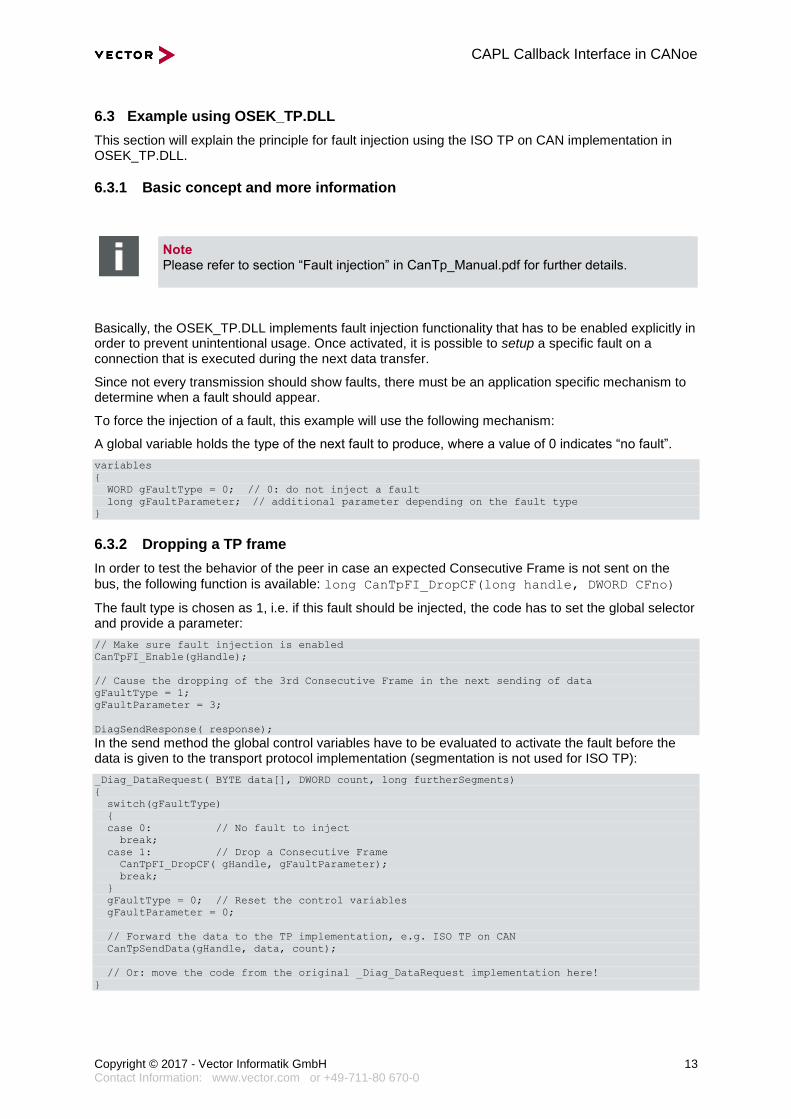
6.3 Example using OSEK_TP.DLL
This section will explain the principle for fault injection using the ISO TP on CAN implementation in OSEK_TP.DLL.
6.3.1 Basic concept and more information
Note Please refer to section “Fault injection” in CanTp_Manual.pdf for further details.
Basically, the OSEK_TP.DLL implements fault injection functionality that has to be enabled explicitly in order to prevent unintentional usage. Once activated, it is possible to setup a specific fault on a connection that is executed during the next data transfer.
Since not every transmission should show faults, there must be an application specific mechanism to determine when a fault should appear.
To force the injection of a fault, this example will use the following mechanism:
A global variable holds the type of the next fault to produce, where a value of 0 indicates “no fault”.
variables
{
WORD gFaultType = 0; // 0: do not inject a fault
long gFaultParameter; // additional parameter depending on the fault type
}
6.3.2 Dropping a TP frame
In order to test the behavior of the peer in case an expected Consecutive Frame is not sent on the
bus, the following function is available: long CanTpFI_DropCF(long handle, DWORD CFno)
The fault type is chosen as 1, i.e. if this fault should be injected, the code has to set the global selector and provide a parameter:
// Make sure fault injection is enabled
CanTpFI_Enable(gHandle);
// Cause the dropping of the 3rd Consecutive Frame in the next sending of data
gFaultType = 1;
gFaultParameter = 3;
DiagSendResponse( response);
In the send method the global control variables have to be evaluated to activate the fault before the data is given to the transport protocol implementation (segmentation is not used for ISO TP):
_Diag_DataRequest( BYTE data[], DWORD count, long furtherSegments)
{
switch(gFaultType)
{
case 0: // No fault to inject
break;
case 1: // Drop a Consecutive Frame
CanTpFI_DropCF( gHandle, gFaultParameter);
break;
}
gFaultType = 0; // Reset the control variables
gFaultParameter = 0;
// Forward the data to the TP implementation, e.g. ISO TP on CAN
CanTpSendData(gHandle, data, count);
// Or: move the code from the original _Diag_DataRequest implementation here!
}
CAPL Callback Interface in CANoe
Copyright © 2017 - Vector Informatik GmbH 14 Contact Information: www.vector.com or +49-711-80 670-0
7.0 Additional Resources
VECTOR APPLICATION NOTE
AN-IND-1-001 CANoe as a Diagnostic Tool
AN-IND-1-004 Diagnostics via Gateway in CANoe
CANOE DOCUMENTATION
Manual Diagnostics on FlexRay
Manual ISO 10681-2 TP for FlexRay
Manual User manual CanTp (OSEK_TP.DLL)
CANOE ADD-ON PACKAGE DOCUMENTATION
VAG package VW TP 2.0 Diagnostics in CANoe
VAG package VW Transport Protocol 2.0 Nodelayer DLL for CANoe
8.0 Contacts
For a full list with all Vector locations and addresses worldwide, please visit http://vector.com/contact/.