Embed Size (px)
Citation preview

ADDENDUM 1
Westmoreland Central School District
Westmoreland, NY
Capital Improvements
Elementary School - SED Control No. 41-28-01-04-0-003-010 High School - SED Control No. 41-28-01-04-0-001-012
Middle School - SED Control No. 41-28-01-04-0-012-004 Bus Garage - SED Control No. 41-28-01-04-5-004-006
Bid Packages: Roofing Construction Sitework Construction Masonry Restoration General Construction Electrical Construction
THIS ADDENDUM IS ISSUED INDICATING CHANGES TO THE ORIGINAL PROJECT MANUAL AND DRAWINGS DATED JUNE 17, 2013. ALL CHANGES SHALL BE INCORPORATED INTO THE CONTRACTOR’S PROPOSAL AS DESCRIBED HEREIN. THIS ADDENDUM SHALL BE CONSIDERED ONE OF THE CONTRACT DOCUMENTS WHEN AN AWARD IS MADE. ACKNOWLEDGMENT OF RECEIPT OF THIS ADDENDUM IS REQUIRED ON THE RESPECTIVE PROPOSAL.
Owner:
Westmoreland CSD 5176 Route 233
Westmoreland, NY 13490 Architect: Landscape Architect: MARCH Associates Appel Osborne 258 Genesee St, Suite 300 102 W. Division St., Suite 400 Utica, NY 13502 Syracuse, NY 13204 Hazardous Materials: Electrical Engineers: Barton & Loguidice Sack & Associates 290 Elwood Davis Rd, Box 3107 721 East Genesee Street Syracuse, NY 13220 Syracuse, NY 13210
MARCH No. 1292
JUNE 27, 2013
ADD-1 MARCH No. 1292
Add-1/Page 1

The following changes, additions, and deletions shall be incorporated into the Project Manual and Drawings. SUPPLEMENTAL INFORMATION: ITEM 1. Refer to the attached Pre-Bid Meeting Minutes, dated June 25th, 2013. ITEM 2. PRE-BID RFI 001: Within the Bus Loop Area – What is the full depth of the existing
leach field for removal? RESPONSE: “We do not have any as-builts for the leach field that would be getting partially removed, but a good assumption is around 3'-0″ depth.”
REFER TO THE SPECIFICATIONS: ITEM 1. SECTION 00 01 10, TABLE OF CONTENTS
A. Page 00 01 10/1. Refer to: DIVISION 0 - BIDDING REQUIREMENTS, CONTRACT
FORMS, CONTRACT CONDITIONS. ADD: “Section 00 31 32, Geotechnical Data”.
B. Page 00 01 10/2. Refer to: DIVISION 7 - THERMAL AND MOISTURE PROTECTION. ADD: “Section 07 81 00, Plastic Unit Skylights”.
C. Page 00 01 10/2. Refer to: DIVISION 26 – ELECTRICAL. ADD the following:
“Section 26 05 43, Underground Ducts and Raceways for Electrical Systems” “Section 26 56 00, Exterior Lighting”
ITEM 2. SECTION 00 31 32, GEOTECHNICAL DATA
A. INSERT new Section 00 31 32, Geotechnical Data, attached. ITEM 3. SECTION 01 22 00, UNIT PRICES
A. Page 01 22 00/2, Subparagraph 1.03.C.3 - Description. REVISE: “Note: 500 CY to be included in the Base Bid.” TO READ: “Note: 750 CY to be included in the Base Bid.”.
ITEM 4. SECTION 07 62 00, ROOF FLASHING
A. Page 07 62 00/1, Paragraph 2.01. DELETE this paragraph in its entirety and REPLACE with the following:
“2.01 FASCIA, FASCIA EXTENSIONS, AND FLASHINGS
A. Fascia, Fascia Extensions, and Flashings shall be manufactured by or
approved by roofing manufacturer and covered under total system roof warranty.
B. Fascia (Econo-Snap 1 as manufactured by W.R. Hickman, or as approved):
1. 0.050 minimum thickness. 2. Formed as indicated. 3. Cleats to be 22 gauge minimum galvanized steel. 4. Concealed splice plates. 5. Finish: Fluoropolymer coating, Kynar 500 resin. 6. Color: Match existing fascia color.”
MARCH No. 1292 Add-1/Page 2
ITEM 5. SECTION 07 81 00, PLASTIC UNIT SKYLIGHTS
A. INSERT new Section 07 81 00, Plastic Unit Skylights, attached. ITEM 6. SECTION 26 05 43, UNDERGROUND DUCTS AND RACEWAYS FOR ELECTRICAL
SYSTEMS
A. ADD new Section 26 05 43, Underground Ducts and Raceways for Electrical Systems, attached.
ITEM 7. SECTION 26 56 00, EXTERIOR LIGHTING
A. ADD new Section 26 56 00, Exterior Lighting, attached. REFER TO THE PROJECT DRAWINGS: ITEM 1. DRAWING COVER
A. Refer to the Drawing Index. Under “Sitework”, ADD the following: “L12 - Details”. ITEM 2. DRAWING AR-3(HS), Basement and Second Floor Asbestos Removal Plan
A. Refer to Material Removal Schedule. DELETE in its entirety: “Remove and dispose of vinyl asbestos floor tile, mastic, cove trim, and underlayment/filler, approximately 1/4″ thick”.
B. Refer to 8/A3, Second Floor Plan. DELETE removal of VAT indicated by cross hatch
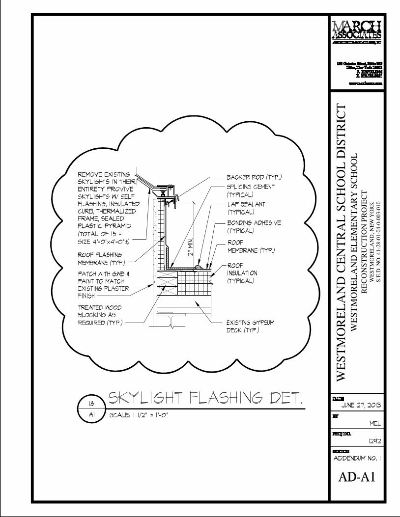
symbol. ITEM 3. DRAWING A1(ES), Roof Plan & Details
A. Refer to Detail #18. DELETE this detail in its entirety and REPLACE with attached Sketch AD-A1.
B. Refer to General Roof Notes, Note No (1). ADD the following:
“On existing metal roofs, existing GWB sheathing to remain. Existing vapor barriers on existing gypsum/metal decks may remain pending full adhesion to deck and approved by roofing manufacturer and covered under total system warranty.”
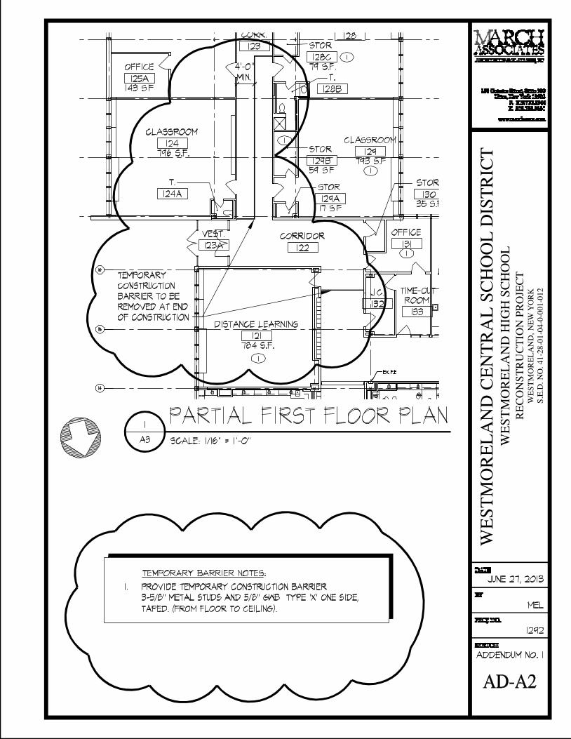
ITEM 4. DRAWING A3(HS), First Floor Plan & Schedule
A. Refer to Detail 1/A3, First Floor Plan. ADD temporary barrier to plan as shown on attached Sketch AD-A2 and ADD temporary barrier notes as shown on Sketch AD-A2.
ITEM 5. DRAWING A4(HS), Roof Plan & Details
A. Refer to Detail 1/A4, Roof Plan. ADD changes to metal panel locations and details and added roof area (18'-0″ x 12'-6″) as shown on attached Sketch AD-A3.
MARCH No. 1292 Add-1/Page 3
B. Refer to General Roof Notes, Note No (1). ADD the following:
“Existing vapor barriers on existing metal and concrete decks may remain pending full adhesion to deck and approved by roofing manufacturer and covered under total system warranty.”
ITEM 6. DRAWING A5(HS), Photos & Details
A. ADD Details 3/A5, 4/A5, 5/A5, and 6/A5 as shown on attached Sketch AD-A4. ITEM 7. DRAWING L11, Details
A. Refer to 4/L11, Baseball Infield Plan. DELETE dimensions indicated for the backstop and ADD the following Note:
“Provide backstop in accordance with dimensions indicated on Drawing L8.”
ITEM 8. DRAWING ES1 – ELECTRICAL SITE PLAN
A. Refer to the Drawing Title Block.
1. CHANGE “Middle School” TO READ: “Elementary and High School”. 2. CHANGE SED No. FROM: “41-28-01-04-0-012-004” TO READ:
“41-28-01-04-0-003-010 (ES) and 41-28-01-04-0-001-012 (HS)”.
B. ADD attached Sketch AD-E1 for the following:
1. ADD Keyed Note 1. 2. ADD three Type "LP1" light poles/luminaires/bases in west parking lot. 3. ADD location of Electric Room and Panels PP-AC/PLC #2. 4. ADD spot light to pole for illuminating flag. 5. ADD removal of existing poles/bases.
C. ADD attached Sketch AD-E2 for the following:
1. ADD Keyed Note 1. 2. ADD one Type "LP1" light poles/luminaires/bases in west driveway. 3. ADD removal of existing poles/bases.
D. ADD attached Sketch AD-E3 for the following:
1. REVISE panel designation in Detail 4/ES1-Site Lighting – Wiring Diagram. 2. REVISE pole style in light fixture schedule.
* * * * *
MARCH No. 1292 Add-1/Page 4

PRE-BID MEETING MINUTES Project: Westmoreland Central School District Capital Improvements Project MARCH #1292 Location: District Board Room Date: Tuesday, June 25, 2013 Present: Name: Company: Email:
Randy Rundle Westmoreland CSD [email protected] Ben Heintz Kestrel Construction Services [email protected] Rob Korrie Beebe Construction Services [email protected] Dave Seymour EZ Paving [email protected] Agustin Martinez Ritter & Paratore [email protected] Andrew Aery Lupini Construction [email protected] Stuart Murphy Murphy Excavating Corp. [email protected] Ray Roorda Central Paving Inc. [email protected] Tim Borza EV Roofing Corp. [email protected] Tony Cavallaro J&B Installations [email protected] Erik Gilroy Davis Wallbridge Inc. [email protected] Paul Lamondo RH Law [email protected] Pete Goodspeed Pulver Roofing [email protected] Asmir Hamzic Heritage Masonry [email protected] Ray Edic Oneida Electrical [email protected] Ron Dittmar Two Brothers Contracting [email protected] Tim Bonaparte Appel Osborne [email protected] Maria Leon MARCH Associates [email protected] Chris Crolius MARCH Associates [email protected]
This meeting was held to initiate the bid phase for the above referenced project. Introductions were made to those present for the School District. It was noted that Ben Heintz will be the Owner’s Representative during the construction phase. The following administrative requirements were reviewed: • Bids are due on Tuesday, July 2nd, 2013 at 3:00 PM in the Board Room. Due to the delay in receiving SED
approval, and the timing of the Bid Opening, a bid extension is not envisioned at this time. • C. Crolius requested that all questions be faxed to MARCH Associates by Noon on Wednesday, 6/26/13.
An addendum will be issued on Thursday, 6/27/13. Questions received after that time will not be able to be answered. MARCH Associates’ Fax Number is 315.733.3331.
• To make arrangements to visit the site after today, call Randy Rundle at 315.557.2682 or Ben Heintz at
315.507.1322. • Contracts will be awarded at the Board Meeting on Tuesday, July 9th. • C. Crolius reviewed the allowances and unit prices in each of the contracts. • It was noted that the undercutting unit price in the Sitework Contract carries a quantity. The amount will
be clarified by addendum. It was also noted that the track resurfacing alternate is all or nothing. If the alternate is not awarded there is no work associated with the track.
MARCH #1292 Pre-Bid Mtg Minutes/Pg. 1

• C. Crolius advised the contractors to carefully review the Summary of Work and reviewed the anticipated completion dates for various contracts.
• It was noted that pavement cores were performed by CME. This information will be sent out with the
addendum for use by the contractors. • C. Crolius noted that there is asbestos abatement shown on the second floor of the High School that is not
required and will be deleted by addendum. • C. Crolius indicated that Masonry Restoration, Roofing, and General Construction all have asbestos
abatement responsibilities contained within their Contracts. • C. Crolius noted that the playscape will be purchased by Westmoreland Central School District under State
Contract; to be received and installed by the Sitework Construction Contract. • Outlined below are the architect’s budgets for the various bid packages:
- Masonry Restoration ............................... $65,000 - Roofing Construction ......................... $1,000,000 - General Construction ............................ $100,000 - Sitework Construction ........................ $1,500,000 - Electrical Construction ............................ $30,000
• T. Bonaparte indicated that there are wetlands and work required in a wet swale. Contractors will need to protect the adjacent sanitary field and work closely and carefully in this area.
• T. Bonaparte noted that there is some debris in the area of the Elementary School drop-off. Contractors
should anticipate some undercutting in this area, which is not included in the 750 CY contained in the unit price. C. Crolius noted that if an excessive amount of material is found this will be reviewed and there are mechanisms within the contract documents to address unforeseen conditions.
• T. Bonaparte indicated that a DOT Permit is required. Discussions have been held with the DOT already. • It was noted that demo of the existing electrical bases and poles will be added by addendum. • This concluded the formal portion of the meeting, at which time the meeting was opened up for questions. Question: Do the contract documents contain the Owner’s OCP Policy for each contract? Response: C. Crolius noted that he believed it did. Contractors should carefully review the Supplementary
Conditions for Insurance requirements, This concluded the pre-bid meeting, at which time a tour of the work areas was conducted.
* * * * *
MARCH #1292 Pre-Bid Mtg Minutes/Pg. 2

DOCUMENT 00 31 32
GEOTECHNICAL DATA PART 1 - GENERAL 1.01 INVESTIGATION
A. Pavement investigations were conducted at the site under the supervision of CME Associates, Inc., 6035 Corporate Drive, East Syracuse, New York 13057.
B. The Summary of Pavement Core Investigation is attached to this section. C. Bidders are urged to examine the pavement investigation data and to make their own
investigation of the site before bidding.
1.02 INTERPRETATION A. Pavement investigation data is provided only for information and the convenience of
bidders. The Owner, Architect and Engineer disclaim any responsibility for the accuracy, true location, and extent of the pavement investigation that has been prepared by others.
B. Geotechnical data is not part of the Contract Documents.
PART 2 - PRODUCTS - Not Used PART 3 - EXECUTION - Not Used
* * * * *
Attachment
MARCH No. 1292 00 31 32/1


SECTION 07 81 00
PLASTIC UNIT SKYLIGHTS PART 1 - GENERAL 1.01 GENERAL DESCRIPTION OF THE WORK INCLUDED BY THIS SECTION
A. Structural design, engineering and fabrication of the extruded aluminum framing, integral closures, trim and perimeter flashing as indicated.
B. Fasteners, anchors and related reinforcement of framing system as required to resist
design loads. C. Glazing materials including gaskets, sealants, spacers, blocking and related materials. D. Installation of entire framed skylight system.
1.02 RELATED SECTIONS
A. Section 07 53 00 - Elastomeric Membrane Roofing. B. Section 07 90 00 - Joint Sealers.
1.03 REFERENCES
A. Aluminum Association (AA): Specifications for Aluminum Structures, AAMA 2603-98, 611-98, and 1605.1.
B. American Architectural Manufacturers Association (AAMA). C. American Society for Testing and Materials (ASTM), D4802, E283, E330, and E331. D. National Roofing Contractors Association (NRCA). E. Surface Burning Characteristics of Building Materials (ASTM) E-84. F. Flammability of Self-Supporting Plastics (ASTM) D-635. G. Ignition Properties of Plastics (ASTM) D-1929.
1.04 PERFORMANCE CRITERIA
A. Framing system including glazing material shall be designed to support the following load requirements: 1. 60 PSF roof snow or live load + dead load 2. 30 PSF positive wind load + dead load 3. 30 PSF negative wind load + dead load 4. Concentrated live load of 250 lbs. applied to any framing member at a location
that will produce the most severe stress or deflection. 5. Thermal load of (± 70 degrees F for heated enclosures or ± 50 degrees F for
unheated enclosures) from ambient temperature. 6. The maximum allowable deflection of any glazing support member shall not
exceed 1/180 times the unsupported span.
MARCH No. 1292 07 81 00/1

B. Air and water resistance 1. Allowable air infiltration shall not exceed 0.01 CFM of the total glazed surface
area when tested in accordance with ASTM E283 at a static pressure of 6.25 PSF.
2. No uncontrolled water leakage shall occur when system is tested in accordance with ASTM E331 at a static pressure of 15 PSF.
C. Required Rating for Plastics:
1. Plastics shall not exceed Flame Spread Rating of 0-25 and Smoke Developed
Rating shall not exceed 450 per ASTM E-84. 2. Self-Supporting Plastics Burning Test shall not exceed 1 inch per minute per
ASTM D-635 (Class CC1). 3. Self-Ignition of Plastic shall not occur below 650°F per ASTM D-1929.
D. Thermal Transmittance, U-Value: Skylight to meet or exceed a thermal transmittance of 0.6.
1.05 SUBMITTALS
A. Shop drawings shall be submitted for approval prior to fabrication. Layout, detail and property note all framing members, glazing materials, sealants, fasteners, anchors, and the thickness and types of formed flashing and closures.
B. Structural calculations shall be prepared in accordance with the Aluminum Association’s
Specifications for Aluminum Structures and AAMA Structural Design Guidelines for Aluminum-Framed Skylights (SDGS-1).
C. Submit samples of each type of finish and glazing material as requested prior to
fabrication.
1. Aluminum finish. 2. Glazing Materials - Samples for verification of plastic glazing material in specified
color.
1.06 QUALITY ASSURANCE
A. Skylight systems shall be manufactured by a firm with a minimum of ten (10) years experience in the fabrication and installation of custom aluminum framed skylights.
1.07 DELIVERY, STORAGE AND HANDLING, JOB CONDITIONS
A. All materials shall be delivered, stored and covered to protect factory finishes from weather damage and construction dirt until installed.
B. Glazing materials shall be packaged to prevent breakage. C. Installed materials, including glass shall be protected from damage by the general
contractor.
1.08 WARRANTY
A. Skylight manufacturer shall warrant that the framing system will be free of defects in materials and workmanship for a period of five (5) years from date of substantial completion.
B. Glazing materials shall be warranted against delamination, seal failure and/or
deterioration of film coatings for a period of five (5) years from the date of manufacture. MARCH No. 1292
07 81 00/2

C. Manufacturer shall guarantee that the installation will remain weathertight for a period of
five (5) years from the date of substantial completion.
PART 2 - PRODUCTS 2.01 MANUFACTURER
A. American Skylites (basis for design). B. Naturalite Skylight Systems, The Vista Group, or as approved equal.
2.02 MATERIALS
A. Insulated Curb Skylights: Factory Assembled self flashing units with plastic domes, 0.060 inch extruded aluminum curb frame, 0.060 inch extruded aluminum retaining angle, double wall insulated curb. Skylight frame to have integral condensate gutter and weep slots. Weeps to be protected from weather and air borne debris. Curbs should be thermally broken and have 3 inch roof flange and a 3/4 inch layer of insulation. 1. Type: Thermally sealed pyramid. 2. Curb Height: 12 inches. 3. Glazing: Polycarbonate. 4. Outer and Inner Colors: Colorless. 5. Frame Finish: Mill finish. 6. Condensate Control: Shall have poured and debridged polyurethane thermal
break and corners shall be factory sealed. 7. Size: Custom size to fit existing openings as indicated.
PART 3 - INSTALLATION 3.01 INSTALLATION
A. Installer shall notify the Architect of deficiencies or dimensional errors in the support and adjacent construction.
B. Skylight materials shall be installed in accordance with manufacturer’s erection drawings
and field instructions. No glazing or sealant work shall be performed when the metal temperature is below 32 degrees F.
C. Contact areas between aluminum and dissimilar materials shall be isolated with a
protective coating or plastic strip to prevent electrolytic corrosion. D. Remove all labels and part numbers markings from components and shall leave the
installation free of all heavy construction dirt and sealant smears.
END OF SECTION
MARCH No. 1292 07 81 00/3

13009ADDN1 MARCH #1292 26 05 43/1
SECTION 26 05 43
UNDERGROUND DUCTS AND RACEWAYS FOR ELECTRICAL SYSTEMS
PART 1 - GENERAL
1.1 SUMMARY
A. Section Includes: 1. Direct-buried conduit, ducts, and duct accessories.
1.2 ACTION SUBMITTALS
A. Product Data: For ducts and conduits, duct-bank materials.
PART 2 - PRODUCTS
2.1 GENERAL REQUIREMENTS FOR DUCTS AND RACEWAYS
A. Comply with ANSI C2.
2.2 CONDUIT
A. Rigid Steel Conduit: Galvanized. Comply with ANSI C80.1.
B. RNC: NEMA TC 2, Type EPC-80-PVC, UL 651, with matching fittings by same manufacturer as the conduit, complying with NEMA TC 3 and UL 514B.
2.3 NONMETALLIC DUCTS AND DUCT ACCESSORIES
A. Available Manufacturers: 1. ARNCO Corp. 2. Cantex, Inc. 3. CertainTeed Corporation. 4. Condux International, Inc. 5. ElecSys, Inc. 6. Electri-Flex Company. 7. IPEX Inc. 8. Lamson & Sessions; Carlon Electrical Products. 9. Spiraduct/AFC Cable Systems, Inc.
B. Underground Plastic Utilities Duct: NEMA TC 2, UL 651, ASTM F 512, Type EPC-80, with matching fittings complying with NEMA TC 3 by same manufacturer as the duct.
PART 3 - EXECUTION
3.1 UNDERGROUND DUCT APPLICATION
A. Ducts for Electrical Feeders 600 V and Less: RNC, NEMA Type EPC-80-PVC, in direct-buried duct bank unless otherwise indicated.
B. Ducts for Electrical Branch Circuits: RNC, NEMA Type EPC-80-PVC, in direct-buried duct bank unless otherwise indicated.
C. Underground Ducts Crossing Paved Paths, Walks, Driveways, and Roadways: RNC, NEMA Type EPC-40-PVC, encased in reinforced concrete.

13009ADDN1 MARCH #1292 26 05 43/2
3.2 EARTHWORK
A. Excavation and Backfill: Comply with Section 31 22 01 "Site Earthwork," but do not use heavy-duty, hydraulic-operated, compaction equipment.
B. Restore areas disturbed by trenching, storing of dirt, cable laying, and other work. Restore vegetation and include necessary topsoiling, fertilizing, liming, seeding, sodding, sprigging, and mulching. Comply with Section 32 92 01 "Seeded and Sodded Lawns."
C. Cut and patch existing pavement in the path of underground ducts and utility structures according to the "Cutting and Patching" Article in Section 01 73 29 "Execution."
3.3 DUCT INSTALLATION
A. Install ducts according to NEMA TCB 2.
B. Joints: Use solvent-cemented joints in ducts and fittings and make watertight according to manufacturer's written instructions. Stagger couplings so those of adjacent ducts do not lie in same plane.
C. Direct-Buried Duct Banks: 1. Excavate trench bottom to provide firm and uniform support for duct bank.
Comply with requirements in Section 31 22 01 "Site Earthwork" for preparation of trench bottoms for pipes less than 6 inches in nominal diameter.
2. Support ducts on duct separators coordinated with duct size, duct spacing, and outdoor temperature.
3. Space separators close enough to prevent sagging and deforming of ducts, with not less than five spacers per 20 feet of duct. Secure separators to earth and to ducts to prevent displacement during backfill and yet permit linear duct movement due to expansion and contraction as temperature changes. Stagger spacers approximately 6 inches between tiers.
4. Depth: Install top of duct bank at least 24 inches below finished grade unless otherwise indicated.
5. Install ducts with a minimum of 3 inches between ducts for like services and 6 inches between power and signal ducts.
6. Install manufactured rigid steel conduit elbows for stub-ups at poles and equipment, at building entrances through floor, and at changes of direction in duct run. a. Couple steel conduits to ducts with adapters designed for this purpose,
and encase coupling with 3 inches of concrete. b. For equipment mounted on outdoor concrete bases, extend steel conduit
horizontally a minimum of 60 inches from edge of equipment pad or foundation. Install insulated grounding bushings on terminations at equipment.
7. After installing first tier of ducts, backfill and compact. Start at tie-in point and work toward end of duct run, leaving ducts at end of run free to move with expansion and contraction as temperature changes during this process. Repeat procedure after placing each tier. After placing last tier, hand place backfill to 4 inches over ducts and hand tamp. Firmly tamp backfill around ducts to provide maximum supporting strength. Use hand tamper only. After placing controlled backfill over final tier, make final duct connections at end of run and complete backfilling with normal compaction. Comply with requirements in Section 31 22 01 "Site Earthwork" for installation of backfill materials. a. Place minimum 3 inches of sand as a bed for duct bank. Place sand to a
minimum of 6 inches above top level of duct bank.
13009ADDN1 MARCH #1292 26 05 43/3
3.4 CLEANING
A. Pull leather-washer-type duct cleaner, with graduated washer sizes, through full length of ducts. Follow with rubber duct swab for final cleaning and to assist in spreading lubricant throughout ducts.
END OF SECTION

13009ADDN1 MARCH #1292 26 56 00/1
SECTION 26 56 00
EXTERIOR LIGHTING
PART 1 - GENERAL
1.1 SUMMARY
A. Section Includes: 1. Exterior luminaires with lamps and ballasts. 2. Poles and accessories.
1.2 ACTION SUBMITTALS
A. Product Data: For each luminaire, pole, and support component, arranged in order of lighting unit designation. Include data on features, accessories, and finishes.
B. Shop Drawings: Anchor-bolt templates keyed to specific poles and certified by manufacturer.
1.3 QUALITY ASSURANCE
A. Electrical Components, Devices, and Accessories: Listed and labeled as defined in NFPA 70, by a qualified testing agency, and marked for intended location and application.
B. Comply with IEEE C2, "National Electrical Safety Code."
C. Comply with NFPA 70.
PART 2 - PRODUCTS
2.1 MANUFACTURERS
A. Products: Subject to compliance with requirements, provide one of the products indicated on Drawings.
2.2 GENERAL REQUIREMENTS FOR LUMINAIRES
A. Luminaires shall comply with UL 1598.
B. Lateral Light Distribution Patterns: Comply with IESNA RP-8 for parameters of lateral light distribution patterns indicated for luminaires.
C. Metal Parts: Free of burrs and sharp corners and edges.
D. Sheet Metal Components: Corrosion-resistant aluminum unless otherwise indicated. Form and support to prevent warping and sagging.
E. Housings: Rigidly formed, weather- and light-tight enclosures that will not warp, sag, or deform in use. Provide filter/breather for enclosed luminaires.
F. Doors, Frames, and Other Internal Access: Smooth operating, free of light leakage under operating conditions, and designed to permit relamping without use of tools. Designed to prevent doors, frames, lenses, diffusers, and other components from falling accidentally
13009ADDN1 MARCH #1292 26 56 00/2
during relamping and when secured in operating position. Doors shall be removable for cleaning or replacing lenses. Designed to disconnect ballast when door opens.
G. Exposed Hardware Material: Stainless steel.
H. Plastic Parts: High resistance to yellowing and other changes due to aging, exposure to heat, and UV radiation.
I. Light Shields: Metal baffles, factory installed and field adjustable, arranged to block light distribution to indicated portion of normally illuminated area or field.
J. Reflecting surfaces shall have minimum reflectance as follows unless otherwise indicated: 1. White Surfaces: 85 percent. 2. Specular Surfaces: 83 percent. 3. Diffusing Specular Surfaces: 75 percent.
K. Lenses and Refractors Gaskets: Use heat- and aging-resistant resilient gaskets to seal and cushion lenses and refractors in luminaire doors.
L. Luminaire Finish: Manufacturer's standard paint applied to factory-assembled and -tested luminaire before shipping. Where indicated, match finish process and color of pole or support materials.
2.3 GENERAL REQUIREMENTS FOR POLES AND SUPPORT COMPONENTS
A. Structural Characteristics: Comply with AASHTO LTS-4-M. 1. Wind-Load Strength of Poles: Adequate at indicated heights above grade without
failure, permanent deflection, or whipping in steady winds of speed indicated in "Structural Analysis Criteria for Pole Selection" Article.
2. Strength Analysis: For each pole, multiply the actual equivalent projected area of luminaires and brackets by a factor of 1.1 to obtain the equivalent projected area to be used in pole selection strength analysis.
B. Luminaire Attachment Provisions: Comply with luminaire manufacturers' mounting requirements. Use stainless-steel fasteners and mounting bolts unless otherwise indicated.
C. Mountings, Fasteners, and Appurtenances: Corrosion-resistant items compatible with support components. 1. Materials: Shall not cause galvanic action at contact points. 2. Anchor Bolts, Leveling Nuts, Bolt Caps, and Washers: Hot-dip galvanized after
fabrication unless otherwise indicated. 3. Anchor-Bolt Template: Plywood or steel.
D. Hand Hole: Oval-shaped, with minimum clear opening of 2-1/2 by 5 inches, with cover secured by stainless-steel captive screws.
2.4 ALUMINUM POLES
A. Poles: ASTM B 209, 5052-H34 marine sheet alloy with access hand hole in pole wall. 1. Shape: Round, straight. 2. Mounting Provisions: Butt flange for bolted mounting on foundation or breakaway
support.
B. Pole-Top Tenons: Fabricated to support luminaire or luminaires and brackets indicated, and securely fastened to pole top.
13009ADDN1 MARCH #1292 26 56 00/3
C. Grounding and Bonding Lugs: Welded 1/2-inch threaded lug, accessible through hand hole.
D. Brackets for Luminaires: Detachable, with pole and adapter fittings of cast aluminum. Adapter fitting welded to pole and bracket, then bolted together with stainless-steel bolts. 1. Tapered oval cross section, with straight tubular end section to accommodate
luminaire. 2. Finish: Same as pole.
E. Aluminum Finish: Same as light fixture.
PART 3 - EXECUTION
3.1 LUMINAIRE INSTALLATION
A. Adjust luminaires that require field adjustment or aiming.
3.2 POLE INSTALLATION
A. Alignment: Align pole foundations and poles for optimum directional alignment of luminaires and their mounting provisions on the pole.
B. Concrete Pole Foundations: Set anchor bolts according to anchor-bolt templates furnished by pole manufacturer.
C. Foundation-Mounted Poles: Mount pole with leveling nuts, and tighten top nuts to torque level recommended by pole manufacturer. 1. Grout void between pole base and foundation. Use non-shrink or expanding
concrete grout firmly packed to fill space. 2. Install base covers unless otherwise indicated. 3. Use a short piece of 1/2-inch- diameter pipe to make a drain hole through grout.
Arrange to drain condensation from interior of pole.
3.3 GROUNDING
A. Ground metal poles and support structures. 1. Install grounding electrode for each pole unless otherwise indicated. 2. Install grounding conductor pigtail in the base for connecting luminaire to
grounding system.
END OF SECTION


![EXHIBIT 5 Rules - SECEXHIBIT 5 (additions are underlined ; deletions are [bracketed]) * * * * * Chicago Board Options Exchange, Incorporated Rules * * * * * Rule 1.1. Definitions When](https://img.pdfslide.us/doc/110x75/60f7fbe721df25209b33a24e/exhibit-5-rules-sec-exhibit-5-additions-are-underlined-deletions-are-bracketed.jpg)