Embed Size (px)
Citation preview

This article was downloaded by: [University of Saskatchewan Library]On: 05 October 2012, At: 18:25Publisher: Taylor & FrancisInforma Ltd Registered in England and Wales Registered Number: 1072954 Registered office: Mortimer House,37-41 Mortimer Street, London W1T 3JH, UK
Heat Transfer EngineeringPublication details, including instructions for authors and subscription information:http://www.tandfonline.com/loi/uhte20
Capillary Filling in Nanochannels—Modeling,Fabrication, and ExperimentsVinh Nguyen Phan a , Pierre Joseph b , Lyes Djeghlaf b , Alaa El Dine Allouch b , DavidBourrier b , Patrick Abgrall a , Anne-Marie Gué b , Chun Yang a & Nam-Trung Nguyen aa School of Mechanical and Aerospace Engineering, Nanyang Technological University,Singaporeb LAAS-CNRS and Université de Toulouse, Toulouse, France
Version of record first published: 16 Nov 2011.
To cite this article: Vinh Nguyen Phan, Pierre Joseph, Lyes Djeghlaf, Alaa El Dine Allouch, David Bourrier, Patrick Abgrall,Anne-Marie Gué, Chun Yang & Nam-Trung Nguyen (2011): Capillary Filling in Nanochannels—Modeling, Fabrication, andExperiments, Heat Transfer Engineering, 32:7-8, 624-635
To link to this article: http://dx.doi.org/10.1080/01457632.2010.509756
PLEASE SCROLL DOWN FOR ARTICLE
Full terms and conditions of use: http://www.tandfonline.com/page/terms-and-conditions
This article may be used for research, teaching, and private study purposes. Any substantial or systematicreproduction, redistribution, reselling, loan, sub-licensing, systematic supply, or distribution in any form toanyone is expressly forbidden.
The publisher does not give any warranty express or implied or make any representation that the contentswill be complete or accurate or up to date. The accuracy of any instructions, formulae, and drug doses shouldbe independently verified with primary sources. The publisher shall not be liable for any loss, actions, claims,proceedings, demand, or costs or damages whatsoever or howsoever caused arising directly or indirectly inconnection with or arising out of the use of this material.

Heat Transfer Engineering, 32(7–8):624–635, 2011Copyright C©© Taylor and Francis Group, LLCISSN: 0145-7632 print / 1521-0537 onlineDOI: 10.1080/01457632.2010.509756
Capillary Fill ing inNanochannels—Modeling,Fabrication, and Experiments
VINH NGUYEN PHAN,1 PIERRE JOSEPH,2 LYES DJEGHLAF,2
ALAA EL DINE ALLOUCH,2 DAVID BOURRIER,2 PATRICK ABGRALL,1
ANNE-MARIE GUE,2 CHUN YANG,1 and NAM-TRUNG NGUYEN1
1School of Mechanical and Aerospace Engineering, Nanyang Technological University, Singapore2LAAS-CNRS and Universite de Toulouse, Toulouse, France
While capillary filling in channels of micrometers scale is experimentally verified to obey Washburn’s law well, the speedof capillary filling in nanochannels is noticeably lower than described by Washburn’s formula. This article reports thetheoretical and experimental results on capillary filling in open-end and closed-end nanochannels. Nanochannels of 45 nmand 80 nm depth, 10 µm width, were etched in silicon and bonded to a glass cover. Experiments on filling of non-electrolyticliquid in silicon nanochannels were carried out. The filling processes were observed and recorded. To estimate the influenceof electrokinetics, a mathematical model to calculate the electroviscous effect was established. This model shows that thecontribution of the electroviscous effect in the reduction of filling speed is small. This result also agrees well with previoustheoretical work on the electroviscous effect. That means that besides the electroviscous effect, there are other phenomenathat contribute to the reduction of capillary filling speed in a nanochannel, such as air bubbles formation. Experimentalinvestigation of capillary filling in open-end and closed-end nanochannels with different lengths was performed. The fillingprocesses of ethanol and isopropanol and the behavior of the trapped air were recorded and evaluated. Analytical modelsbased on the continuum assumption were used to evaluate the experimental data. We observed that the filling process consistsof two stages. At the initial stage, experimental data agree well with the theoretical model, but with a higher apparent viscosity.In the final stage, condensation of the liquid phase and dissolution of the gas phase lead to total filling of the nanochannel.The observed phenomena are important for understanding the behavior of multiphase systems in nanochannels.
INTRODUCTION
The increasing use of semiconductor devices and the increas-ing spatial density of these devices lead to the demand for newtechnologies for heat exchangers [1]. As air-cooling technologymay soon become insufficient, liquid cooling promises to re-place air-cooling technology in the near future [2]. The higherheat transfer rate is based on the fact that the heat conductivity ofliquid is generally higher than that of air. For instance, the heatconductivity of water of 0.58 W/m-K is more than 20 times ofthat of air (0.024 W/m-K). Thermal properties of liquid flow inmicrochannels and millichannels have been studied intensivelyin the past [3]. Weisberg et al. [4] numerically investigated a heatexchanger using microchannels. The authors also suggested a
Address correspondence to Professor Nam-Trung Nguyen, School of Me-chanical and Aerospace Engineering, Nanyang Technological University, 50Nanyang Avenue 639798, Singapore. E-mail: [email protected]
formulation to design such a heat exchanger. Peng et al. per-formed a series of works [5–8] on liquid flow and heat transferin microchannels. Similar investigations of fluid flow and heattransfer in microchannels and their applications were discussedby other authors [9–14].
As the characteristic size of the channel gets smaller, theratio between surface area and volume increases. Therefore,microscale phenomena are more favorable for heat transfer[15]. However, studies on heat transfer in nanochannels withcharacteristic dimensions ranging from several to hundreds ofnanometers are still at an early stage. One of the difficulties ininvestigation of heat transfer at the nanoscale is that the trans-port phenomena of fluid flow in nanostructure have not beenfully understood.
In recent years, advances in micro/nanotechnologies al-lowed the fabrication of structures at nanoscale [16–21]. Var-ious techniques and devices for transport, handling, and ma-nipulating fluid in micro-/nanoscale were developed [22–24].
624
Dow
nloa
ded
by [
Uni
vers
ity o
f Sa
skat
chew
an L
ibra
ry]
at 1
8:25
05
Oct
ober
201
2
V. N. PHAN ET AL. 625
These technological advances allow more sophisticated investi-gation of transport phenomena in nanoscale. Many experimentson capillary filling in nanochannels have been carried out in re-cent years [25–30]. The experimental results revealed that capil-lary filling in the nanochannel qualitatively follows Washburn’sequation. However, the filling speed observed experimentally isusually lower than expected by the classic Washburn’s formula,which is equivalent to an increase in apparent viscosity.
Several efforts were reported to explain the variation be-tween experimental and theoretical results of capillary filling innanochannels. Van Honschoten et al. [31] suggested a model ofelastocapillary filling in deformable channels. The deformationof nanochannels due to high negative pressure across the menis-cus may cause variation in apparent viscosity. Because of thehigh surface-to-volume ratio of the nanochannels, it is believedthat surface effects such as electroviscous effect contribute tothe increase in apparent viscosity [32–35]. Han et al. [26] inves-tigated the filling kinetics of different liquids in nanochannelswith rectangular cross section. Trapping of air bubbles duringthe filling processes was observed.
The formation of air bubbles depends on the interaction be-tween gas and liquid in nanoscale. However, most of the knowl-edge gained in the past was based on macroscopic investigationof porous materials. For instance, Shaw reported experimentalresults of the evaporation process in porous materials [36]. Thiswork set the foundation for subsequent research on modeling ofdrying processes in porous materials. Prat used the invasion per-colation theory to model the drying process in porous material[37]. Yiotis et al. presented a theoretical model for the dryingprocess in porous materials [38]. The results showed that theformation of a liquid film accelerates the drying process.
In this article, we report theoretical and experimental re-sults on capillary filling in open-end and closed-end nanochan-nels. Capillary filling experiment in the open-end nanochannelwere performed with non-electrolytic liquids (ethanol and iso-propanol) to minimize possible electroviscous effects. A simplemathematical model to evaluate the contribution of the electro-viscous effect in the increase of apparent viscosity is also intro-duced. The results from the theoretical model are then comparedto the experimental value above to estimate the general signifi-cance of the electroviscous effect in the overall increase of appar-ent viscosity. Closed-end nanochannels offer an ideal platformfor studying multiphase-related phenomena at the nanoscale,such as condensation. In our work, quantitative measurementsof filling lengths versus time were obtained for isopropanol andethanol. We also investigated the behavior of trapped air duringthe filling process. Under the high Laplace pressure, condensa-tion of the liquid phase followed by dissolution of the gas phaseare the main phenomena observed in the nanoscale confinement.
THEORY
Capillary filling in open-end and closed-end planarnanochannels with a height of h, a width of w, and an aspectratio of w/h � 1 is considered. The driving force depends on
the surface tension of the fluid and the contact angle betweenthe fluid and the channel wall,
Fs = 2σw cos θ (1)
where Fs is the capillary force at the contact line caused bysurface tension σ, and θ is the contact angle between the fluidand the wall surface. In this investigation, the variation of sur-face energy due to accumulation of charged particles near themeniscus, as described in the Gibbs–Duhem equation, is ig-nored. It was reported in the literature that the liquid slip at thesolid–liquid interface [39] and the interaction with electroki-netic effects [40] may lead to modification of effective contactangle. However, in capillary filling of nanochannels the shearstress and streaming voltage diminish quickly. Under such con-ditions the change in effective contact angle is negligible. Thevelocity profile in capillary filling flow is considered the sameas in pressure-driven flow. Due to low Reynolds number, theflow resistance caused by an entrance effect as discussed in re-cent investigations [41–44] is ignored. In the case of a planarnanochannel, the velocity profile has a parabolic form [45]. Theviscous force is then given by
Fv =(
µdu
dy
∣∣∣∣y= h
2
− µdu
dy
∣∣∣∣y=− h
2
)wx = −12µu
hwx (2)
where Fv is the viscosity force acting on the fluid, x is the fillinglength, u = dx/dt is the filling speed, and µ is the dynamicviscosity of the fluid. The filling process is considered to begin atthe entrance of the channel; hence the initial condition x = 0 att = 0 is applied to both closed-end and open-end nanochannels.
Capillary Filling in Open-End Nanochannels
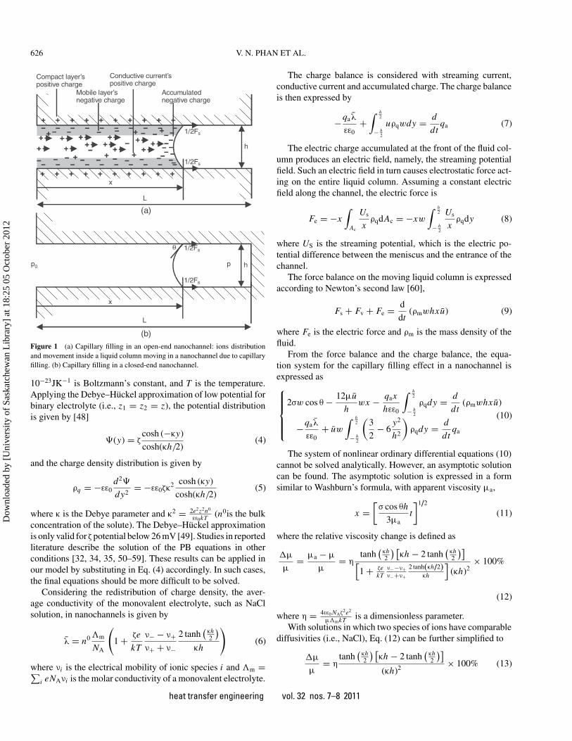
Figure 1a shows the model of capillary filling process inan open-end nanochannel, with consideration of electroviscouseffect. Without any lost of generality, the wall of the channelis assumed to be positively charged, through the selective ab-sorption of cations. The shaded areas in Figure 1a represent theelectrical double layer (EDL). The streaming voltage causedby the accumulation of anion at the meniscus generated a con-ductive current, as well as the electric force against the fillingmovement. The reduction of filling speed represents the increasein apparent viscosity [46].
In a nanochannel, the electric potential distributionand the charge density distribution is governed by thePoisson–Boltzmann (PB) equation [47, 48]:
∇2� = − ρq
εε0= − e
εε0
∑i
zi n0i exp
(− zi e�
kT
)(3)
where � is the electrostatic potential, ρq is the charge density,e = 1.6021 × 10⁻¹⁹C is the elementary charge, ε is the relativepermittivity of the fluid, ε0 = 8.854×10⁻¹²CV−1m−1 is thepermittivity of vacuum, zi is the charge number of ionic speciesi, n0
i is the bulk concentration of ionic species i, k = 1.381 ×heat transfer engineering vol. 32 nos. 7–8 2011
Dow
nloa
ded
by [
Uni
vers
ity o
f Sa
skat
chew
an L
ibra
ry]
at 1
8:25
05
Oct
ober
201
2
626 V. N. PHAN ET AL.
x
Compact layer’s positive charge
Mobile layer’s negative charge
Accumulatednegative charge
Conductive current’spositive charge
h
1/2Fs
1/2Fs
(a)
L
x
h
1/2Fs
1/2Fs
(b)
p0 p
L
θ
Figure 1 (a) Capillary filling in an open-end nanochannel: ions distributionand movement inside a liquid column moving in a nanochannel due to capillaryfilling. (b) Capillary filling in a closed-end nanochannel.
10−23JK−1 is Boltzmann’s constant, and T is the temperature.Applying the Debye–Huckel approximation of low potential forbinary electrolyte (i.e., z1 = z2 = z), the potential distributionis given by [48]
�(y) = ζcosh (−κy)
cosh(κh/2)(4)
and the charge density distribution is given by
ρq = −εε0d2�
dy2= −εε0ζκ
2 cosh (κy)
cosh(κh/2)(5)
where κ is the Debye parameter and κ2 = 2e2z2n0
εε0kT (n0is the bulkconcentration of the solute). The Debye–Huckel approximationis only valid for ζ potential below 26 mV [49]. Studies in reportedliterature describe the solution of the PB equations in otherconditions [32, 34, 35, 50–59]. These results can be applied inour model by substituting in Eq. (4) accordingly. In such cases,the final equations should be more difficult to be solved.
Considering the redistribution of charge density, the aver-age conductivity of the monovalent electrolyte, such as NaClsolution, in nanochannels is given by
λ = n0 �m
NA
(1 + ζe
kT
ν− − ν+ν+ + ν−
2 tanh(
κh2
)κh
)(6)
where νi is the electrical mobility of ionic species i and �m =∑i eNAνi is the molar conductivity of a monovalent electrolyte.
The charge balance is considered with streaming current,conductive current and accumulated charge. The charge balanceis then expressed by
−qaλ
εε0+∫ h
2
− h2
uρqwdy = d
dtqa (7)
The electric charge accumulated at the front of the fluid col-umn produces an electric field, namely, the streaming potentialfield. Such an electric field in turn causes electrostatic force act-ing on the entire liquid column. Assuming a constant electricfield along the channel, the electric force is
Fe = −x∫
Ac
Us
xρqdAc = −xw
∫ h2
− h2
Us
xρqdy (8)
where US is the streaming potential, which is the electric po-tential difference between the meniscus and the entrance of thechannel.
The force balance on the moving liquid column is expressedaccording to Newton’s second law [60],
Fs + Fv + Fe = d
dt(ρmwhxu) (9)
where Fe is the electric force and ρm is the mass density of thefluid.
From the force balance and the charge balance, the equa-tion system for the capillary filling effect in a nanochannel isexpressed as⎧⎪⎪⎪⎨⎪⎪⎪⎩
2σw cos θ − 12µu
hwx − qax
hεε0
∫ h2
− h2
ρqdy = d
dt(ρmwhxu)
−qaλ
εε0+ uw
∫ h2
− h2
(3
2− 6
y2
h2
)ρqdy = d
dtqa
(10)
The system of nonlinear ordinary differential equations (10)cannot be solved analytically. However, an asymptotic solutioncan be found. The asymptotic solution is expressed in a formsimilar to Washburn’s formula, with apparent viscosity µa,
x =[σ cos θh
3µat
]1/2
(11)
where the relative viscosity change is defined as
�µ
µ= µa − µ
µ= η
tanh(
κh2
) [κh − 2 tanh
(κh2
)][1 + ζe
kTν−−ν+ν−+ν+
2 tanh(κh/2)κh
](κh)2
× 100%
(12)
where η = 4εε0 NAζ2e2
µ�mkT is a dimensionless parameter.With solutions in which two species of ions have comparable
diffusivities (i.e., NaCl), Eq. (12) can be further simplified to
�µ
µ= η
tanh(
κh2
) [κh − 2 tanh
(κh2
)](κh)2 × 100% (13)
heat transfer engineering vol. 32 nos. 7–8 2011
Dow
nloa
ded
by [
Uni
vers
ity o
f Sa
skat
chew
an L
ibra
ry]
at 1
8:25
05
Oct
ober
201
2

V. N. PHAN ET AL. 627
10-2
10-1
100
101
102
103
0
2
4
6
8
10
12
14
Dimensionless channel height kh
Rel
ativ
e vi
scos
ity c
hang
e ∆µ
/µ (%
)
Comparable ionic mobility
Different ionic mobility
Figure 2 Relative viscosity change (Solid line: values predicted by the currenttheory. Dashed line: values reported by Mortensen and Kristensen).
Figure 2 presents the relative viscosity change predicted byEq. (13), in comparison to the values reported by Mortensen andKristensen [33], under the same condition.
Capillary Filling in Closed-End Nanochannels
Figure 1b illustrates the capillary filling process in a closed-end nanochannel. Both trapped air and filling liquid are con-sidered as continua. Condensation of the liquid phase and dis-solution of the gas phase are neglected. The forces governingthe filling process of a closed-end nanochannel are the capillaryforce Fs, the viscous force Fv, and the resistance force of thetrapped and compressed air,
FP = −hwp0x/(L − x) (14)
where L is the total length of the nanochannel and p0 is theinitial pressure of the trapped air. The electroviscous effect isnot considered in this model. Since inertia force is negligible innanoscale, the force balance Fs + Fv + Fp = 0 leads to
dx
dt= hσ cos θ
6µx− h2 p0
12µ (L − x)(15)
The parameters of Eq. (15) are made dimensionless as x∗ =x/L , t∗ = t/2τ, and α = hp0
/2σ cos θ, where α represents the
ratio of force due to the trapped air pressure over the capillaryforce, and τ = 3µL2/hσ cos θ is the required time to fill anopen-end channel of the same length L . The governing Eq. (15)has then the dimensionless form
dx∗
dt∗ = 1
x∗ − α
1 − x∗ (16)
Integrating the preceding equation with the initial conditiont∗ (0) = 0 for any x∗
0 < 1/
(1 + α) leads to the relationship:
t∗(x∗) = x∗2
2(1 + α
) − αx∗(1 + α
)2
− α(1 + α
)3 ln[1 − (
1 + α)x∗] (17)
The final position of the liquid column can be derived fromEq. (17) as:
limt∗→∞ x∗ = 1
1 + α(18)
If condensation and dissolution are neglected, the fillinglength x of the liquid cannot exceed L/(1 + α). At this finallength, the magnitude of the resistance force of the trapped airis equal to that of the capillary force, Fs + Fp = 0. For the caseof 45-nm-height nanochannels, the Laplace pressure caused byethanol is approximately 9.96 bars.
EXPERIMENTS
Fabrication and Experimental Setup
Figure 3 depicts the schematic designs of the open-end andclosed-end nanochannels under investigation. Nanochannels of
Silicon
Nanochannel
Microchannel
Reservoir
(a)
(b)
w h x
L
Silicon
Nanochannel
Microchannel
Reservoirw x
L
Glass
Glass
Figure 3 Schematic design of the test chip with nanochannels, microchannels,and reservoirs etched in silicon: (a) open-end nanochannels; (b) closed-endnanochannels.
heat transfer engineering vol. 32 nos. 7–8 2011
Dow
nloa
ded
by [
Uni
vers
ity o
f Sa
skat
chew
an L
ibra
ry]
at 1
8:25
05
Oct
ober
201
2

628 V. N. PHAN ET AL.
Figure 4 (a) The fabricated channel network. (b) Filling of liquid in nanochannels.
10 µm width and 45 nm and 80 nm depth were fabricated insilicon by reactive ion etching (RIE). The length of closed-endnanochannels ranges from 10 µm to 8 mm. For each channeldimension, a set of 10 channels was designed for obtaining goodstatistics in later experiments. Microchannels with a cross sec-tion of 8 µm × 100 µm, which connected to the nanochannels,were realized by deep reactive ion etching (DRIE). Both ends ofthe microchannels are accessible through 1-mm-diameter reser-voirs etched through the silicon wafer using a long DRIE pro-cess. Lastly, a Pyrex glass plate was anodically bonded to thesilicon wafer to seal the nanochannels. Bonding was performedat 350◦C and 400 V. Figure 4a shows the fabricated channelnetwork consisting of the access hole, the microchannel and thenanochannels. A typical filling process of open-end nanochan-nels is shown in Figure 4b.
In our experiments, nanochannels with reservoirs facing upwere observed and recorded with an inverted microscope (ZeissObserver D1) and a camera (EMCCD AndorIQ, Andor Technol-ogy PLC, Northern Ireland). The liquid (ethanol or isopropanol)was introduced into one of the reservoirs and filled the mi-crochannel and nanochannels by capillary force. To keep ethanolfrom wetting the outer surface of the chip, a spacer made of poly-dimethylsiloxane (PDMS) was placed above the reservoir. Thedata were recorded as 16-bit gray-scale multi-images uncom-pressed tagged image files (TIF) with a size of 1004 pixels ×1002 pixels. The temperature and relative humidity were mea-sured before each experiment. The surface tension and viscositywere derived from the temperature, using a formula providedby Yaws [61]. The environmental temperature during the exper-iments for both cases of ethanol and isopropanol is measured as26 ± 1◦C. The relative humidity of the environment was 48%.
According to the formula provided by [61], the relative variationin surface tension and viscosity is less than 1%, which is consid-ered to be negligible. Macroscopic contact angle measurementrevealed that both liquids under investigation totally wet siliconand glass (θ = 0◦).
In the experiment with closed-end nanochannels, the fill-ing processes were observed with different magnifications andtime scales. The experiment consists of two steps. In the firststep, we recorded the filling process from the entrance of thenanochannels until the end of the 3-mm-long channel set. Ob-jective lens with a magnification of 2.5× was used for thispurpose. The field of view was approximately 3 mm × 3 mm.The exposure time was 10 ms. Images were recorded with aframe rate of 17 fps. In the second step, one of the closed endsof the nanochannels was chosen to investigate the behavior ofthe advancing meniscus and of the trapped air. A magnificationof 20× and a frame rate of 5 fps were used for this experi-ment. The images were recorded to observe the slow process ofcondensation and dissolution until the nanochannels were fullyfilled.
Experiment Result
The square of filling distance versus time characteristics, asshown in Figure 5, reveals that capillary filling in open-endnanochannels qualitatively follows Washburn’s formula,
x =[σ cos θh
3µt
]1/2
(19)
heat transfer engineering vol. 32 nos. 7–8 2011
Dow
nloa
ded
by [
Uni
vers
ity o
f Sa
skat
chew
an L
ibra
ry]
at 1
8:25
05
Oct
ober
201
2

V. N. PHAN ET AL. 629
9876543210Time (s)
0
0.2
0.4
0.6
0.8
1
1.2
1.4
Squ
are
of fi
lling
leng
th (
mm
)2
Experimental value in 45-nm channel
Theoretical value in 45-nm channel
Experimental value in 80-nm channelTheoretical value in 80-nm channel
Figure 5 Square of filling length versus filling time in open-end nanochannelsin a typical filling process of isopropanol in 45-nm and 80-nm nanochannels.
However, quantitative analysis shows that the Washburn co-efficient,
a =√
σ cos θh
3µ(20)
is lower than predicted by the classical Washburn’s theory, whichis equivalent to an increase in apparent viscosity. Table 1 lists themeasured relative viscosity change of ethanol and isopropanol.It is reported in recent investigations that the electroviscouseffect is the cause of reduction of speed in pressure-driven flowand even capillary filling [32–35]. However, as derived from Eq.(13), which indicates that the dimensionless parameter η is onthe order of unity for most of electrolytic solutions (i.e., η ≈ 0.5for NaCl 0.01 M solution), the maximum increase in apparentviscosity is not more than 5%. In our capillary filling experiment,non-electrolytic liquids that exhibit negligible electroviscouseffect also encounter a relatively high viscosity increase ratio, asshown in Table 1. Therefore, there are other phenomena besidesthe electroviscous effect that cause the increase in apparentviscosity of liquid in nanochannels. There are reports on theformation of air bubbles during the filling process [8–11]. Afraction of energy is stored in terms of surface energy of theair bubbles. Hence, less energy transfers into kinetic energyof the fluid column, leading to a reduction in filling speed.Additionally, the presence of bubbles modifies the flow profile
Table 1 Relative viscosity change of different fluids and channel geometries
Relative viscosity change (%)
Fluid Channel height (nm) Mean Std. dev.
Isopropanol 45 28.0 6.10Isopropanol 80 9.70 1.00Ethanol 45 21.5 2.00Ethanol 80 9.30 3.60
Fill
ing
leng
th x
(m
m)
Filling time t (s)
t*
t*
x*x*
(b)
(c)
0 10 20 30 40 50 60 70 80 90 1000
0.5
1
1.5
2
2.5
(a)
0 0.5 1 1.5 2 2.5 3 3.5 4 4.50
0.1
0.2
0.3
0.4
0.5
0.6
0.7
0.8
0.9
1
0 0.5 1 1.5 2 2.5 3 3.50
0.1
0.2
0.3
0.4
0.5
0.6
0.7
0.8
0.9
1
500um1mm1.5mm2mm2.5mm
500um1mm1.5mm2mm2.5mm
Theory
500um1mm1.5mm2mm2.5mm
Theory with increased viscosity
Figure 6 Filling process of isopropanol in closed-end nanochannels of differ-ent lengths, 45 nm depth, and 10 µm width: (a) filling length versus time; (b)normalized filling length versus normalized time; (c) normalized filling lengthversus normalized time with apparent viscosity µa=1.8 µ.
and may lead to an increase in viscous dissipation, and thus toa slower filling.
Figure 6a shows the measured filling length of isopropanolin closed-end nanochannels with different lengths. The graphshows an identical filling pattern for all nanochannels with dif-ferent lengths in the first stage. When the meniscus of the liquidapproaches the end of the channel, the filling process beginsto slow down. Figure 6b depicts the normalized filling lengthas a function of normalized time in comparison to the theo-retical behavior predicted by Eq. (17) with the bulk value ofviscosity. The results show that the filling speed in the first stageis actually lower than predicted by theory. This behavior was
heat transfer engineering vol. 32 nos. 7–8 2011
Dow
nloa
ded
by [
Uni
vers
ity o
f Sa
skat
chew
an L
ibra
ry]
at 1
8:25
05
Oct
ober
201
2
630 V. N. PHAN ET AL.
Fill
ing
leng
th x
(m
m)
Filling time t (s)
t*
t*
x*x*
(b)
(c)
(a)
0 10 20 30 40 50 60 70 800
0.5
1
1.5
2
2.5
0 0.5 1 1.5 2 2.5 3 3.5 4 4.50
0.1
0.2
0.3
0.4
0.5
0.6
0.7
0.8
0.9
1
0 0.5 1 1.5 2 2.5 3 3.5 40
0.10.2
0.3
0.4
0.5
0.6
0.7
0.8
0.9
1
500um1mm1.5mm2mm2.5mm
500um1mm1.5mm2mm2.5mm
Theory
500um1mm1.5mm2mm2.5mm
Theory with increased viscosity
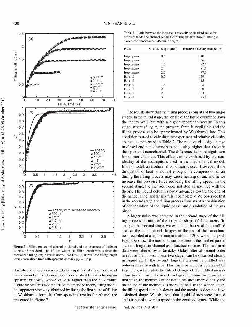
Figure 7 Filling process of ethanol in closed-end nanochannels of differentlengths, 45 nm depth, and 10 µm width: (a) filling length versus time; (b)normalized filling length versus normalized time; (c) normalized filling lengthversus normalized time with apparent viscosity µa = 1.8 µ.
also observed in previous works on capillary filling of open-endnanochannels. The phenomenon is described by introducing anapparent viscosity, whose value is higher than the bulk value.Figure 6c presents a comparison to amended theory using modi-fied apparent viscosity, obtained by fitting the first stage of fillingto Washburn’s formula. Corresponding results for ethanol arepresented in Figure 7.
Table 2 Ratio between the increase in viscosity to standard value fordifferent fluids and channel geometries during the first stage of filling inclosed-end nanochannel (45 nm in height)
Fluid Channel length (mm) Relative viscosity change (%)
Isopropanol 0.5 140Isopropanol 1 136Isopropanol 1.5 92.0Isopropanol 2 81.0Isopropanol 2.5 77.0Ethanol 0.5 149Ethanol 1 115Ethanol 1.5 108Ethanol 2 108Ethanol 2.5 103Ethanol 3 95.0
The results show that the filling process consists of two majorstages. In the initial stage, the length of the liquid column followsthe theory well, but with a higher apparent viscosity. In thisstage, where t∗ τ, the pressure force is negligible and thefilling process can be approximated by Washburn’s law. Thiscondition is used to calculate the experimental relative viscositychange, as presented in Table 2. The relative viscosity changein closed-end nanochannels is noticeably higher than those inthe open-end nanochannel. The difference is more significantfor shorter channels. This effect can be explained by the non-ideality of the assumptions used in the mathematical model.In this model, an isothermal condition is used. However, if thedissipation of heat is not fast enough, the compression of airduring the filling process may cause heating of air, and henceincrease the pressure force reducing the filling speed. In thesecond stage, the meniscus does not stop as assumed with thetheory. The liquid column slowly advances toward the end ofthe nanochannel and finally fills it completely. We observed thatin the second stage, the filling process consists of a combinationof condensation of the liquid phase and dissolution of the gasphase.
A larger noise was detected in the second stage of the fill-ing process because of the irregular shape of filled areas. Toanalyze this second stage, we evaluated the remaining unfilledarea of the nanochannel. Images of the end of the nanochan-nels recorded at a higher magnification of 20× were analyzed.Figure 8a shows the measured surface area of the unfilled part ina 2-mm-long nanochannel as a function of time. The measureddata were filtered by a Savitzky–Golay filter of second orderto reduce the noises. These two stages can be observed clearlyin Figure 8a. In the second stage the amount of unfilled areareduces linearly with time. This linear behavior is confirmed byFigure 8b, which plots the rate of change of the unfilled area asa function of time. The inserts in Figure 8a show that during thefirst stage, the meniscus of the liquid advances more quickly andthe shape of the meniscus is more defined. In the second stage,the filling speed is much slower and the meniscus does not havea defined shape. We observed that liquid islands were formedand air bubbles were trapped in the confined space. While the
heat transfer engineering vol. 32 nos. 7–8 2011
Dow
nloa
ded
by [
Uni
vers
ity o
f Sa
skat
chew
an L
ibra
ry]
at 1
8:25
05
Oct
ober
201
2

V. N. PHAN ET AL. 631
Figure 8 Final stage of capillary filling in closed-end nanochannels: (a) surface area of the unfilled part at the end of a 2-mm-long nanochannel as function oftime (the starting time is arbitrary); (b) rate of change of the surface area in (a).
liquid islands spread, the encircled bubbles reduced their sizeand gradually disappeared. This phenomenon can be consideredas a combination of gas dissolution and liquid condensation andprobably is enhanced by film flows and corner flows [25]. Theadvance movement of the meniscus in the second stage is gov-erned by the dissolution of gas into liquid and the diffusionof the gas molecules out of the nanochannels. Due to the highpressure of the trapped gas, which is approximately equal tothe Laplace pressure, the gas molecules dissolve into the liquidphase, and the concentration of gas molecules at the meniscusin the liquid phase is determined by the Henry’s law. Due to thedifference in gas molecules concentration between the meniscusand the entrance of the nanochannel, the gas molecules diffuseout of the channel. The diffusion rate of the gas molecules deter-mines the advancing rate of the meniscus. A detailed theoretical
analysis on this phenomenon is beyond the scope of this arti-cle and is considered in our future work. The evaporation andcondensation of liquids is properly due to thermal fluctuation.These phenomena lead to the formation of liquid islands andair bubbles, which cause local instability of the meniscus in thesecond stage. However, because the diffusion process only de-pends on the global concentration gradient in the nanochannel,local instability caused by evaporation and condensation shouldnot affect the average advancing rate of the meniscus.
CONCLUSIONS
This article reports the theoretical and experimental resultson capillary filling in open-end and closed-end nanochannels.
heat transfer engineering vol. 32 nos. 7–8 2011
Dow
nloa
ded
by [
Uni
vers
ity o
f Sa
skat
chew
an L
ibra
ry]
at 1
8:25
05
Oct
ober
201
2

632 V. N. PHAN ET AL.
The nanochannels of 45 nm and 80 nm depths and 10 µmwidth were fabricated by a standard plasma etching process ina silicon wafer. A Pyrex glass cover was anodically bonded tothe silicon wafer to seal the nanochannels. The nanochannelswere then filled with non-electrolytic liquid. The filling pro-cesses were observed and recorded. A mathematical model tocalculate the electroviscous effect was established. This modelshows that the contribution of the electroviscous effect in thereduction of filling speed is small. The result agrees well withprevious theoretical works on the electroviscous effect. Conse-quently, there exist other phenomena involved in the variationin Washburn’s coefficient, such as the formation of air bubbles.The capillary filling processes of closed-end nanochannels werealso recorded and compared to a simple theoretical model thatneglects the condensation of the liquid and the dissolution of gas.The data show clearly two stages of the filling process. In thefirst stage, the experimental data agree well with the theory, butwith a higher apparent viscosity. However, in the second stage,the menisci do not stop at the critical position predicted by thetheory, but continue to fill until the end of the nanochannels. Aquantitative analysis of this stage shows a linear relationship be-tween the filling area and the time. High-magnification imagesreveal that in this stage liquid islands form, while gas bubblestrapped in the nanochannels dissolve into the liquid. The airbubbles reduce their size before totally disappearing. This phe-nomenon suggests that condensation of liquid and dissolution ofgas are important processes at the nanoscale, where the Laplacepressure is relatively high. The observed condensation and dis-solution phenomena can affect transport processes of liquid innanochannels.
NOMENCLATURE
a Washburn’s coefficientA area of trapped airAc cross-sectional area of the channelDRIE deep reactive ion etchinge elementary charge, 1.305 × 10⁻¹⁹CEDL electric double layerFe electrical forceFs surface force, capillary forceFv viscous drag forceFp pressurized force of trapped airh channel heightk Boltzmann’s constant, 1.381 × 10⁻²³JK−1
L channel lengthn local concentrationn0 bulk concentrationNA Avogadro’s number, 6.0221415 × 10²³
p0 pressurep0 initial (atmospheric) pressureqa accumulated charget time variablet∗ dimensionless time
T room temperatureu fluid velocityUS streaming potentialw channel widthx capillary filling lengthx∗ dimensionless filling lengthx∗
0 initial dimensionless filling lengthy coordinate across the channel heightz charge number
Greek Symbols
α ratio between initial pressure and Laplace pressure�µ increase in dynamic viscosityε relative permittivity of the fluidε0 permittivity of free space, 8.854 × 10⁻¹² CV−1 m−1
ζ zeta potentialη material dimensionless parameterθ contact angleκ inverse of Debye thicknessλ conductivity of the fluid�m molar conductivity of solutionµ dynamic viscosityµa apparent dynamic viscosity>σ surface tensionρm mass density of the fluidρq charge densityτ characteristic filling timeυ ion mobility� electrostatic potential across the channel’s height
Subscripts
0 initial condition+ positive ion− negative iona apparent, accumulatedc cross sectionE electricm molar, massp pressurizedq charges surfaceS streamingv viscous
Superscripts
− average value across the heightˆ divided by channel width w
i belong to ion species i
heat transfer engineering vol. 32 nos. 7–8 2011
Dow
nloa
ded
by [
Uni
vers
ity o
f Sa
skat
chew
an L
ibra
ry]
at 1
8:25
05
Oct
ober
201
2

V. N. PHAN ET AL. 633
REFERENCES
[1] Kandlikar, S. G., and Grande, W. J., Evaluation of SinglePhase Flow in Microchannels for High Heat Flux ChipCooling-Thermohydraulic Performance Enhancement andFabrication Technology, Heat Transfer Engineering, vol.25, no. 8, pp. 5–16, 2004.
[2] Cheng, L., Bandarra Filho, E. P., and Thome J. R.,Nanofluid Two-Phase Flow and Thermal Physics: A NewResearch Frontier of Nanotechnology and Its Challenges,Journal of Nanoscience and Nanotechnology, vol. 8, no.7, pp. 3315–3332, 2008.
[3] Roday, A. P., and Jensen M. K., A Review of the CriticalHeat Flux Condition in Mini- and Microchannels, Journalof Mechanical Science and Technology, vol. 23, no. 9, pp.2529–2547, 2009.
[4] Weisberg, A., Bau, H. H., and Zemel, J. N., Analysis of Mi-crochannels for Integrated Cooling, International Journalof Heat and Mass Transfer, vol. 35, no. 10, pp. 2465–2474,1992.
[5] Peng, X.F., and Wang, B.X., Forced Convection and FlowBoiling Heat Transfer for Liquid Flowing Through Mi-crochannels, International Journal of Heat and MassTransfer, vol. 36, no.14, pp. 3421–3427, 1993.
[6] Peng, X. F., and Peterson, G. P., The Effect of Thermofluidand Geometrical Parameters on Convection of LiquidsThrough Rectangular Microchannels, International Jour-nal of Heat and Mass Transfer, vol. 38, no. 4, pp. 755–758,1995.
[7] Peng, X. F., Wang, B. X., Peterson, G. P., and Ma, H. B.,Experimental Investigation of Heat Transfer in Flat PlatesWith Rectangular Microchannels, International Journal ofHeat and Mass Transfer, vol. 38, no. 1, pp. 127–137, 1995.
[8] Peng X. F., and Peterson, G. P., Convective Heat Transferand Flow Friction for Water Flow in Microchannel Struc-tures, International Journal of Heat and Mass Transfer,vol. 39, no. 12, pp. 2599–2608, 1996.
[9] Hetsroni, G., Mosyak, A., and Segal, Z., NonuniformTemperature Distribution in Electronic Devices Cooledby Flow in Parallel Microchannels, IEEE Transactions onComponents and Packaging Technologies, vol. 24, no. 1,pp. 16–23, 2001.
[10] Schubert, K., Brandner, J., Fichtner, M., Linder, G.,Schygulla, U., and Wenka, A., Microstructure Devices forApplications in Thermal and Chemical Process Engineer-ing, Microscale Thermophysical Engineering, vol. 5, no.1, pp. 17–39, 2001.
[11] Zhang, J., Tan, K. L., Hong, G. D., Yang, L. J., and Gong,H. Q., Polymerization Optimization of SU-8 Photoresistand Its Applications in Microfluidic Systems and MEMS,Journal of Micromechanics and Microengineering, vol. 11,no. 1, pp. 20–26, 2001.
[12] Kawaji, M., and Chung, P. M. Y., Adiabatic Gas–LiquidFlow in Microchannels, Microscale Thermophysical Engi-neering, vol. 8, no. 3, pp. 239–257, 2004.
[13] Kang, M. K., Shin, J. H., Lee, H. H., and Chun, K., Anal-ysis of Laminar Convective Heat Transfer in Micro HeatExchanger for Stacked Multi-Chip Module, MicrosystemTechnologies, vol. 11, no. 11, pp. 1176–1186, 2005.
[14] Ohta H., Boiling and Two-Phase Flow in Channels WithExtremely Small Dimensions: A Review of Japanese Re-search, Microfluidics and Nanofluidics, vol. 1, no. 2, pp.94–107, 2005.
[15] Rosa P., Karayiannis, T.G., and Collins, M.W., Single-Phase Heat Transfer in Microchannels: The Importance ofScaling Effects, Applied Thermal Engineering, vol. 29, no.17–18, pp. 3447–3468, 2009.
[16] Eijkel, J. C. T., and Van Den Berg, A., Nanofluidics: WhatIs It and What Can We Expect From It?, Microfluidics andNanofluidics, vol. 1, no. 3, pp. 249–267, 2005.
[17] Mijatovic, D., Eijkel, J. C. T., and Van Den Berg, A., Tech-nologies for Nanofluidic Systems: Top-Down vs. Bottom-up—A Review, Lab on a Chip–Miniaturisation for Chem-istry and Biology, vol. 5, no. 5, pp. 492–500, 2005.
[18] Perry, J. L., and Kandlikar, S. G., Review of Fabrication ofNanochannels for Single Phase Liquid Flow, Microfluidicsand Nanofluidics, vol. 2, no. 3, pp. 185–193, 2006.
[19] Yuan Z., Garcia, A. L., Lopez, G. P., and Petsev, D.N., Electrokinetic Transport and Separations in Flu-idic Nanochannels, Electrophoresis, vol. 28, no. 4, pp.595–610, 2007.
[20] Abgrall, P., Low, L. N., and Nguyen, N. T., Fabrication ofPlanar Nanofluidic Channels in a Thermoplastic by Hot-Embossing and Thermal Bonding, Lab on a Chip - Minia-turisation for Chemistry and Biology, vol. 7, no. 4, pp.520–522, 2007.
[21] Abgrall, P., and Nguyen, N. T., Nanofluidic Devices andTheir Applications, Analytical Chemistry, vol. 80, no. 7,pp. 2326–2341, 2008.
[22] Nguyen, N. T., and Truong, T. Q., A Fully Polymeric Mi-cropump With Piezoelectric Actuator, Sensors and Actua-tors, B: Chemical, vol. 97, no. 1, pp. 137–143, 2004.
[23] Nguyen, N. T., and White, R. M., Acoustic Streaming inMicromachined Flexural Plate Wave Devices: NumericalSimulation and Experimental Verification, IEEE Transac-tions on Ultrasonics, Ferroelectrics, and Frequency Con-trol, vol. 47, no. 6, pp. 1463–1471, 2000.
[24] Truong, T. Q., and Nguyen, N. T., A Polymeric Piezoelec-tric Micropump Based on Lamination Technology, Journalof Micromechanics and Microengineering, vol. 14, no. 4,pp. 632–638, 2004.
[25] Eijkel, J. C. T., Dan, B., Reemeijer, H.W., Hermes, D. C.,Bomer, J. G., and Van Den Berg, A., Strongly Acceler-ated and Humidity-Independent Drying of NanochannelsInduced By Sharp Corners, Physical Review Letters, vol.95, no. 25, art. no. 256107, pp. 1–4, 2005.
[26] Han, A., Mondin, G., Hegelbach, N. G., de Rooij, N. F., andStaufer, U., Filling Kinetics of Liquids in Nanochannels asNarrow as 27 nm by Capillary Force, Journal of Colloidand Interface Science, vol. 293, no. 1, pp. 151–157, 2006.
heat transfer engineering vol. 32 nos. 7–8 2011
Dow
nloa
ded
by [
Uni
vers
ity o
f Sa
skat
chew
an L
ibra
ry]
at 1
8:25
05
Oct
ober
201
2

634 V. N. PHAN ET AL.
[27] Persson, F., Thamdrup, L. H., Mikkelsen, M. B. L., Jaarl-gard, S. E., Skafte-Pedersen, P., Bruus, H., and Kristensen,A., Double Thermal Oxidation Scheme for the Fabricationof SiO2 Nanochannels, Nanotechnology, vol. 18, no. 24,art. no. 245301, 2007.
[28] Tas, N. R., Haneveld, J., Jansen, H. V., Elwenspoek, M.,and Van Den Berg, A., Capillary Filling Speed of Waterin Nanochannels, Applied Physics Letters, vol. 85, no. 15,pp. 3274–3276, 2004.
[29] Thamdrup, L. H., Persson, F., Bruus, H., Kristensen, A.,and Flyvbjerg, H., Experimental Investigation of BubbleFormation During Capillary Filling of SiO2 Nanoslits, Ap-plied Physics Letters, vol. 91, no. 16, art. no. 163505, pp.1–3, 2007.
[30] Nguyen, N. T., and Huang X. Y., Thermocapillary Ef-fect of a Liquid Plug in Transient Temperature Fields,Japanese Journal of Applied Physics, Part 1: Regular Pa-pers and Short Notes and Review Papers, vol. 44, no. 2,pp. 1139–1142, 2005.
[31] van Honschoten, J. W., Escalante, M., Tas, N. R., Jansen,H. V., and Elwenspoek, M., Elastocapillary Filling of De-formable Nanochannels, Journal of Applied Physics, vol.101, no. 9, art. no. 094310, pp. 1–7, 2007.
[32] Huang, K. D., and Yang, R. J., Electrokinetic Behaviour ofOverlapped Electric Double Layers in Nanofluidic Chan-nels, Nanotechnology, vol. 18, no. 11, art. no. 115701, pp.1–6, 2007.
[33] Mortensen, N. A., and Kristensen, A., Electroviscous Ef-fects in Capillary Filling of Nanochannels, Applied PhysicsLetters, vol. 92, no. 6, art. no. 063110, pp. 1–3, 2008.
[34] Ren, C. L., and Li, D., Improved Understanding of theEffect of Electrical Double Layer on Pressure-Driven Flowin Microchannels, Analytica Chimica Acta, vol. 531, no.1, pp. 15–23, 2005.
[35] Yang, C., and Li, D., Electrokinetic Effects on Pressure-Driven Liquid Flows in Rectangular Microchannels, Jour-nal of Colloid and Interface Science, vol. 194, no. 1, pp.95–107, 1997.
[36] Shaw, T. M., Drying as an Immiscible Displacement Pro-cess With Fluid Counterflow, Physical Review Letters, vol.59, no. 15, pp. 1671–1674, 1987.
[37] Prat, M., Percolation Model of Drying Under IsothermalConditions in Porous Media, International Journal of Mul-tiphase Flow, vol. 19, no. 4, pp. 691–704, 1993.
[38] Yiotis, A. G., Boudouvis, A. G., Stubos, A. K., Tsim-panogiannis, I. N., and Yortsos, Y. C., Effect of LiquidFilms on the Isothermal Drying of Porous Media, PhysicalReview—Statistical, Nonlinear, and Soft Matter Physics,vol. 68, no. 32, art. no. 037303, pp. 1–4, 2003.
[39] Yang, J., Lu, F., and Kwok, D. Y., Dynamic Interfacial Ef-fect of Electroosmotic Slip Flow With a Moving CapillaryFront in Hydrophobic Circular Microchannels, Journal ofChemical Physics, vol. 121, no. 15, pp. 7443–7448, 2004.
[40] Chakraborty, D., and Chakraborty, S., Interfacial Phenom-ena and Dynamic Contact Angle Modulation in Micro-
capillary Flows Subjected to Electroosmotic Actuation,Langmuir, vol. 24, no. 17, pp. 9449–9459, 2008.
[41] Chakraborty, S., Electroosmotically Driven CapillaryTransport of Typical Non-Newtonian Biofluids in Rect-angular Microchannels, Analytica Chimica Acta, vol. 605,no. 2, pp. 175–184, 2007.
[42] Chakraborty, S., and Mittal, R., Droplet Dynamics in a Mi-crochannel Subjected to Electrocapillary Actuation, Jour-nal of Applied Physics, vol. 101, no. 10, art. no. 104901,pp. 1–8, 2007.
[43] Huang, W., Bhullar, R. S., and Yuan, C. F., The Surface-Tension-Driven Flow of Blood From a Droplet Into a Cap-illary Tube, Journal of Biomechanical Engineering, vol.123, no. 5, pp. 446–454, 2001.
[44] Chakraborty, S., Dynamics of Capillary Flow of Blood Intoa Microfluidic Channel, Lab on a Chip—Miniaturisationfor Chemistry and Biology, vol. 5, no. 4, pp. 421–430,2005.
[45] Kundu, P. K., Fluid Mechanics, 3rd ed., Elsevier AcademicPress, Amsterdam, 1990.
[46] Phan, V. N., Yang, C., and Nguyen, N. T., Analysis of Cap-illary Filling in Nanochannels With Electroviscous Effects,Microfluidics and Nanofluidics, vol. 7, no. 4, pp. 1–12,2009.
[47] Debye, P., and Huckel, E., The Theory of Electrolytes.I. Lowering of Freezing Point and Related Phenomena,Physikalische Zeitschrift, vol. 24, no. 1, pp. 185–206, 1923.
[48] Yuan, Z., Garcia, A. L., Lopez, G. P., and Petsev,D. N., Electrokinetic Transport and Separations in Flu-idic Nanochannels, Electrophoresis, vol. 28, no. 4, pp.595–610, 2008.
[49] Conlisk, A. T., The Debye-Huckel Approximation: ItsUse in Describing Electroosmotic Flow in Micro- andNanochannels, Electrophoresis, vol. 26, no. 10, pp.1896–1912, 2005.
[50] Bowen, W. R., and Jenner, F., Dynamic UltrafiltrationModel for Charged Colloidal Dispersions: A Wigner–SeitzCell Approach, Chemical Engineering Science, vol. 50, no.11, pp. 1707–1736, 1995.
[51] Burgreen, D., and Nakache, F. R., Electrokinetic Flow inUltrafine Capillary Slits, Journal of Physical Chemistry,vol. 68, no. 5, pp. 1084–1091, 1964.
[52] Hsu, J. P., Kao, C. Y., Tseng, S., and Chen, C. J., Electroki-netic Flow Through an Elliptical Microchannel: Effects ofAspect Ratio and Electrical Boundary Conditions, Jour-nal of Colloid and Interface Science, vol. 248, no. 1, pp.176–184, 2002.
[53] Hunter, R. J., Zeta Potential in Colloid Science: Principlesand Applications, Academic Press, London, 1981.
[54] Levine, S., Marriott, J. R., Neale, G., and Epstein, N., The-ory of Electrokinetic Flow in Fine Cylindrical Capillariesat High Zeta-Potentials, Journal of Colloid and InterfaceScience, vol. 52, no. 1, pp. 136–149, 1975.
[55] Levine, S., Marriott, J. R., and Robinson, K., Theory ofElectrokinetic Flow in a Narrow Parallel-Plate Channel,
heat transfer engineering vol. 32 nos. 7–8 2011
Dow
nloa
ded
by [
Uni
vers
ity o
f Sa
skat
chew
an L
ibra
ry]
at 1
8:25
05
Oct
ober
201
2

V. N. PHAN ET AL. 635
Journal of the Chemical Society, Faraday Transactions 2:Molecular and Chemical Physics, vol. 71, no. 1, pp. 1–11,1975.
[56] Levine, S., and Neale, G. H., The Prediction of Electroki-netic Phenomena Within Multiparticle Systems. I. Elec-trophoresis and Electroosmosis, Journal of Colloid andInterface Science, vol. 47, no. 2, pp. 520–529, 1974.
[57] Rice, C. L., and Whitehead, R., Electrokinetic Flow in aNarrow Cylindrical Capillary, Journal of Physical Chem-istry, vol. 69, no. 11, pp. 4017–4023, 1965.
[58] Russel, W. B., Saville, D. A., and Schowalter, W. R., Col-loidal Dispersions, Cambridge University Press, London,1989.
[59] Verwey, E. J. W., and Overbeek, J. T. G., Theory and Sta-bility of Lyophobic Colloids, Elsevier, Amsterdam, 1948.
[60] Phan, V. N., Yang, C., and Nguyen, N. T., Analysis of Cap-illary Filling in Nanochannels With Electroviscous Effects,Microfluidics and Nanofluidics, vol. 7, no. 4, pp. 519–530,2009.
[61] Yaws, C. L., Thermal Physical Properties, William An-drew, New York, 2008.
Vinh Nguyen Phan received his B.E. in 2006 fromthe School of Mechanical and Aerospace Engineering(MAE), Nanyang Technological University (NTU),Singapore. Currently, he is a Ph.D. student at MAE,NTU. His research interests are in nanoscale transportphenomena, especially capillary filling, evaporation,condensation, and multiphase flows.
Pierre Joseph received his Ph.D. in physics of liquidsfrom University Pierre et Marie Curie in Paris (MMNlaboratory, ESPCI) in 2005. In 2005–2007, he workedas a postdoctoral fellow in PMCN laboratory (CNRS-University Lyon 1, France) on flows along superhy-drophobic surfaces. He is currently a CNRS researchassociate at LAAS-CNRS in Toulouse (France),working on nanofluidic technologies, instrumenta-tion, and flow control. He is co-author of a bookchapter and several publications on microfluidics andnanofluidics.Lyes Djeghlaf received his Dip.-Ing. in electronicsin 2006, from University of Science and Technol-ogy USTHB, Algeria, and a master’s diploma inmicro and nano systems from Paul Sabatier Uni-versity Toulouse III, France, in 2009. In 2007 heworked as a technical manager in Mzitec (com-pany of import–export medical material, Algeria).Since January 2010 he has been a Ph.D. studentin LAAS-CNRS (Toulouse, France) working on thecoupling between electrochemistry and microfluidics(electrochemical micro sensor, ChemFET).Alaa El Dine Allouch received his master’s diplomafrom Paul Sabatier University (Toulouse, France) in2008, in the field of micro and nano systems. SinceOctober 2008 he has been a Ph.D. student at LAAS-CNRS (Toulouse, France), working on the generationand control of bubbles and droplets generated insidemicro- and nanochannels.
David Bourrier is an assistant engineer at LAAS-CNRS (Toulouse, France), a laboratory of the Na-tional Research Center. He works in the TEAM incharge of the facilities and the support developmenton MEMS research. His current research interests arein the areas of molds realization and electroplating.He works on the development of new photoresists andon electroplating optimization. He has coauthored 37papers and a patent.
Patrick Abgrall is a postdoctoral researcher atthe Biomedical Diagnostics Institute in Dublin. Heearned his Ph.D. with a thesis on polymer fabrica-tion for lab-on-chips at LAAS-CNRS in Toulouse,France. He was a member of the Singapore-MIT al-liance, where his research was focused on the fabrica-tion and applications of polymer nanofluidic devices.
Anne-Marie Gue studied physics at the National In-stitute for Applied Science and received her Ph.D.degree at the University of Toulouse, France. Shejoined LAAS-CNRS in 1988 as a CNRS senior sci-entist. Since 1994, she has been involved in the de-velopment of microtechnologies and microsystemsfor chemical and biological applications. She firstworked in the design and fabrication of miniaturizedchemical and biosensors. Her activity is now focusingon microfluidic aspects. She has been the head of the
Microsystem and System Integration Group at LAAS-CNRS from 1999 to 2006,and has coauthored more than 90 articles and international communications, and6 patents.
Chun Yang obtained his B.Sc. degree from theDepartment of Thermal Engineering at TsinghuaUniversity in 1985, master’s degree in engineeringthermophysics from the University of Science andTechnology of China in 1988, and Ph.D. degreein mechanical engineering from the Universityof Alberta in 1999. In 1999, he joined NanyangTechnological University, Singapore, and now isan associate professor in the School of Mechanicaland Aerospace Engineering. He is the author and
co-author of more than 100 publications in referred international journals,and has co-authored one textbook entitled Elementary Electrokinetic Flow. Heserves as a member of the editorial advisory board for Journal of Microfluidicsand Nanofluidics and International Journal of Emerging MultidisciplinaryFluid Sciences. He is a reviewer for the Research Grant Council of HongKong, Research Grant Council of Australia, National Science and EngineeringResearch Council of Canada, and Dutch Technology Foundation, and also apeer reviewer for more than 30 international journals.
Nam-Trung Nguyen received his Dip.-Ing., Dr. Ing.,and Dr. Ing. Habil, degrees from Chemnitz Universityof Technology, Germany, in 1993, 1997, and 2004,respectively. In 1998, he worked as a postdoctoralresearch engineer in the Berkeley Sensor and Actua-tor Center (University of California–Berkeley). Cur-rently, he is an associate professor with the School ofMechanical and Aerospace Engineering of the NTUin Singapore. His research is focused on microfluidicsand instrumentation for biomedical applications. He
has published a number of research papers on microfluidics. The first and sec-ond editions of his bestseller Fundamentals and Applications of Microfluidicsco-authored with S. Wereley were published in 2002 and 2006, respectively. Hislatest book Nanofluidics, co-authored with P. Abgrall, was published in 2009.
heat transfer engineering vol. 32 nos. 7–8 2011
Dow
nloa
ded
by [
Uni
vers
ity o
f Sa
skat
chew
an L
ibra
ry]
at 1
8:25
05
Oct
ober
201
2