Embed Size (px)
Citation preview

DT6220DT6222DT6230
Quick Manual
capaNCDT 6200
US

MICRO-EPSILON MESSTECHNIKGmbH & Co. KGKönigbacher Strasse 15
94496 Ortenburg / Germany
Tel. +49 (0) 8542 / 168-0 Fax +49 (0) 8542 / 168-90e-mail [email protected]
You can find more information about the measurement system in the instruction manual. They are available online at: www.micro-epsilon.de/download/manuals/man--capaNCDT-6200--en.pdf www.micro-epsilon.de/download/manuals/man--capaNCDT-6222--en.pdf or on the CD supplied.

Page 3
General
capaNCDT 6220/6222/6230
General
Symbols UsedThe following symbols are used in this document:
Indicates a hazardous situation which, if not avoided, may result in minor or moderate injury.
Indicates a situation that may result in property damage if not avoided.
Indicates a user action.
i Indicates a tip for users.
Sensor measurement direction
WarningsDisconnect the power supply before touching the sensor surface.
> Risk of injury, static discharge
Connect the power supply and the display/output device according to the safety regulations for electrical equipment.
> Risk of injury, damage to or destruction of the sensor and/or the controller
Avoid shocks and impacts to the sensor and the controller. > Damage to or destruction of the sensor and/or the controller
The supply voltage must not exceed the specified limits. > Damage to or destruction of the sensor and/or the controller
Protect the sensor cable against damage. > Destruction of the sensor, failure of the measurement system.
Page 4
General
capaNCDT 6220/6222/6230
Intended Use - The measuring system is designed for use in an industrial environment. It is used for
� measuring displacement, distance movement and thickness, � measuring the position of parts or machine components.
- The measuring system must only be operated within the limits specified in the technical data. The measuring system must be used in such a way that no persons are endangered or machines and other mate-
rial goods are damaged in the event of malfunction or total failure of the controller.. Take additional precautions for safety and damage prevention in case of safety-related applications.
Page 5
General
capaNCDT 6220/6222/6230
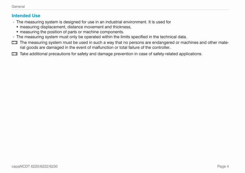
Proper Environment
Controller Operating temperature Storage temperature+10 ... +60 °C (+50 ... +140 °F)
-10 ... +75 °C (+14 ... +167 °F)
Sensor Operating temperature Storage temperatureCS005, CS02, CS05, CS08, CS1, CS2, CS3, CS5, CS10
-50 ... +200 °C (-58 ... +392 °F)
-50 ... +200 °C (-58 ... +392 °F)
CSH02, CSH05, CSH1, CSH1.2, CSH2CSH02FL, CSH05FL, CSH1FL, CSH1.2FL, CSH2FL, CSH3FLCSE05, CSE1, CSE2CS1HP CSG0.50, CSG1.00 -50 ... +100 °C
(-58 ... +212 °F)-50 ... +100 °C (-58 ... +212 °F)
Sensor cable Operating temperature Storage temperatureUp to 10,000 operating hours Permanent
CCgxC, CCgxC/90 -20 ... +100 °C (-4 ... +212 °F)
-20 ... +80 °C (-4 ... +176 °F)
-50 ... +80 °C (-58 ... +176 °F)CCgxB , CCgxB/90
CCmxC, CCmxC/90 -100 ... +200 °C (-148 ... +392 °F)
-50 ... +200 °C (-58 ... +392 °F)CCmxB, CCmxB/90
Protection class IP 40Humidity 5 - 95 % (non-condensing)Ambient pressure Atmospheric pressureThe space between sensor surface and target must have an unchanging dielectric constant.

Page 6
General
capaNCDT 6220/6222/6230
Setup, Connection OptionsPower supply and signal output are provided via plug con-nectors on the front of the controller.
SPS
SC
AC
x/4
Ethernet
EtherCAT(optional)
CCxxx
LAN cable RJ-45 connectors
Controller
Sensor
PC
DDxx
Run
X1
X2
EtherAT
PS 2020
PC
6200
-3/4

Page 7
General
capaNCDT 6220/6222/6230
Ground Connection, Grounding Ensure sufficient grounding of the target, for example, by connecting it to the sensor or the power supply ground.
If necessary, use the grounding connection on the housing cover. The grounding connection is included in the conversion kit supplied in the scope of delivery.
Non-contact target groundingGrounding the target is very difficult or even impossible in many applications. Unlike common systems, the target does not need to be grounded if two DL62xx demodulators are synchronized.The schematic diagram below shows two synchronized capaNCDT sensors that measure against a roll. Since the sen-sors are connected by MICRO-EPSILON’s unique synchronization technology, grounding of the target is not required in most cases.
sync.ControllerSensor
Sensor
Controller
1
Position and imbalance measurement with two measure-ment systems
Grounding connection on the housing cover (1)
Target grounding is not required with synchronized capaNCDT sensors by Micro-Epsilon.

Page 8
General
capaNCDT 6220/6222/6230
SynchronizationAll sensors are synchronized with each other within one DT6220/6222/6230 controller. Several capaNCDT 6230 series controllers can be operated simultaneously as a multi-channel system. Synchronizing the controllers prevents interfer-ence of the sensors with each other.
External synchronization DT6230
PIN Assignment Insulation Color
1
2 5
3 4
POWER/TRIG.OUT
SYNCINET
HERC
AT IN
1 n.c. - -
2 Twisted pair 1 1 white 1
3 Twisted pair 1 blue blue
4 Twisted pair 2 2 white 2
5 Twisted pair 2 orange orangeSC6000-x is an assembled synchronization cable which is 0.3 or 1 m long
View: solder side, 5-pin ODU male cable connector
IN/OUT sync on the controller, 5-pin female connector
ETH
ER
CA
T N
YNCN
UT
ETH
ER
CA
T U
TE
THE
RN
ET
POWER TRIG.
DT6230 DL6230
SENSOR/CP
Range
LP Fi ter
Ze o
Zero
I NAL OUT
DL6230
ENSOR/CP
Range
LP Fil er
Zero
Ze o
IGNAL OUT
ETH
ER
CA
T N
YNCIN
OUT
ETH
ER
CA
T U
TE
THE
RN
ET
POWER/TRIG.
DT6230 DL6230
ENSOR/ P
Range
LP Fil er
Zero
Zero
SIGNAL OUT
DL6230
SENSOR/CP
Range
LP Fi ter
Ze o
Zero
I NAL OUT
SC6000-x
Controller 1 Controller 2
Plug the SC6000-x synchronization cable into the SYNC OUT port (output) on Controller 1.
Plug the connector of the SC6000-x into the SYNC IN port (input) on Controller 2.
i Automatic synchronization, each controller can be the master.
Synchronization of a second DT6230 controller

Page 9
Assembly
capaNCDT 6220/6222/6230
AssemblyNo sharp or heavy objects should be allowed to affect the cable sheath.
i A damaged cable cannot be repaired. Tension on the cable is not permitted!
Sensor
Flush installation
Protruding installation
Recessed installation, not for sensors in the CSE series
During installation, take care that the sensor front face is not scratched.
Clamping Around Circumference, Cylindrical Sensors
3 mmfree
Clamping around circumference, assembly with clamp-ing collet
- High reliability - Flat clamping across cylindrical housing - Recommended assembly for e.g., machines, produc-tion facilities, etc.
Radial Spot Clamping with Grub Screw, Cylindrical Sensors
1
Radial spot clamping with grub screw (1)
- Simple mounting option - Recommended assembly only for installation loca-tions that are free of impact or vibration
- The grub screw must be made of plastic
Do not use metal grub screws! > Risk of damage to the sensor
Flat Sensors
Screwed connection from top
Screwed connection from bottom

Page 10
Assembly
capaNCDT 6220/6222/6230
Controller
34 25 125
90
DT 6220 DL 6220
890
125
5 8
8
54
M4
50
2x M
4
Dimensional drawing of base module and demodulator module
Dimensional drawing of housing cover

Page 11
Assembly
capaNCDT 6220/6222/6230
Inserting Demodulator Module Loosen the sleeve nuts (4b) on the right side of the controller, remove the right housing cover (3). Pull out a sleeve nut (4a), including the threaded rod (1). Replace the threaded rod (1) with the next-longest threaded rod in the conversion kit supplied. Push the new
threaded rod, including sleeve nut (4a), through the modules. Replace the remaining 3 threaded rods in the same manner. Attach the additional demodulator module.
POWER/TRIG.
DT6220 DL6220 DL6220
SENSOR/CP
Range
LP Filter
Ze o
Zero
SIGNAL OUT
SENSOR/CP
Range
LP Filter
Zero
Zero
SIGNAL OUT
1 4b2 34a Base module
Demodulator
ETH
ER
CA
T O
UT
ETH
ER
NE
T
Number of demodulator modules
Length of threaded rod M4
1 59 mm2 84 mm3 109 mm4 134 mm
Controller mechanical parts
i Only touch the demodulator modules on the housing, not on the electronics. This avoids elec-trostatic discharges onto the electronics.
Page 12
Assembly
capaNCDT 6220/6222/6230
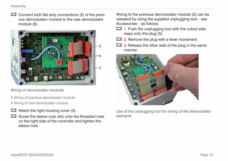
Connect both flat strip connections (5) of the previ-ous demodulator module to the new demodulator module (6).
5
5
6
Wiring of demodulator modules
5 Wiring of previous demodulator module6 Wiring of next demodulator module
Attach the right housing cover (3). Screw the sleeve nuts (4b) onto the threaded rods
on the right side of the controller and tighten the sleeve nuts.
Wiring to the previous demodulator module (5) can be released by using the supplied unplugging tool – see Accessories – as follows:
1. Push the unplugging tool with the cutout side-ways onto the plug (5).
2. Remove the plug with a lever movement. 3. Release the other side of the plug in the same
manner.
Use of the unplugging tool for wiring of the demodulator elements
Page 13
Commissioning
capaNCDT 6220/6222/6230
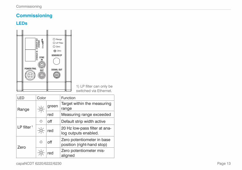
CommissioningLEDs
SIGNAL OUT
SENSOR/CP
Range
LP Filter
Zero
Zero
POWER/TRIG.OUT
SYNCINET
HERC
AT IN
ETHE
RCAT
OUT
ETHE
RNET
1) LP filter can only be switched via Ethernet.
LED Color Function
Rangegreen Target within the measuring
rangered Measuring range exceeded
LP filter 1
off Default strip width active
red 20 Hz low-pass filter at ana-log outputs enabled.
Zerooff Zero potentiometer in base
position (right-hand stop)
red Zero potentiometer mis-aligned

Page 14
Commissioning
capaNCDT 6220/6222/6230
Pin Assignment Supply, TriggerPIN Wire color
PC6200-3/4Signal Description
14
23
DT62xx
POWER/TRIG.OUT
SYNCINET
HERC
AT IN
ETHE
RCAT
OUT
ETHE
RNET
1 brown +24VIN +24 VDC supply
2 white Zero VIN GND supply
3 yellow TRI_IN+ Trigger IN+, TTL level
4 green TRI_IN- Trigger IN-
Shield
PC6200-3/4 is an assembled supply and trigger cable that is 3 m long.
View: solder side, 4-pin ODU female connector
Supply input on controller, 4-pin plug
Pin Assignment of Analog Output
Pin Wire color SCACx/4 Signal Description
1 4
2 3SIGNAL OUT
SENSOR/CP
Range
LP Filter
Zero
Zero
DL62xx
1 brown U-out U OUT, (Load min. 10 kOhm)
2 yellow I-out I OUT, (Load max. 500 Ohm)
3 gray AGND Analog ground
4 white AGND Analog ground
Shield
Analog grounds are connected internally. SCACx/4 is a 4-wire output cable that is 3 m long. It is supplied as an optional accessory.
View: soldering pin side, 4-pin male cable connec-
tor
Signal output on controller, 4-pin port

Page 15
Commissioning
capaNCDT 6220/6222/6230
Ethernet/EtherCAT Switching DT6230
Switch for changing between Ethernet and EtherCAT
You can change between Ethernet and EtherCAT by using the hardware switch on the DT6230 base module or in the software.If the switch is in the EN (Ethernet) position, the Ethernet interface is always active irrespective of the software setting. If the switch is in the EN/EC (Ethernet/EtherCAT) position, the interface set by the software is active. Any change to the interface only takes effect after restarting the controller.

Page 16
Commissioning, IP Address
capaNCDT 6220/6222/6230
Commissioning, IP Address
The controller is shipped with the factory-set IP address 169.254.168.150. You can query the IP addresses of the controllers that are connected to a PC or network by using the Sen-sorFinder.exe program. You will find this program on the supplied CD.
Start SensorFinder and click the Start Scan button.
Select the correct controller from the list. Click the Start Browser button to connect the
sensor to your default browser.
OR: If DHCP is active and the DHCP server is linked to the DNS server, access is also possible by using e.g., DT6200_SN01234567 (where “01234567” is the serial number of your controller).
Start a web browser on your PC. Enter DT6200_Serial_number in the address bar of your brows-er.
The controller supports UPnP. If you have an operating system where the UPnP service is enabled, e.g. by de-fault in Windows 7, the controller is automatically listed in Explorer under network devices and can be accessed from there, e.g. if you have forgotten its IP address.
First interactive web page after calling the IP addressAdditional help functions (e.g. Settings) are available in the top navigation bar. All settings on the web page are implemented in the controller immediately after clicking the Apply button.Parallel operation with web browser and Telnet com-mands is possible; the last setting applies.

Page 17
Commissioning, IP Address
capaNCDT 6220/6222/6230
The appearance of the web pages can change depend-ing on the functions and the peripherals. Each page contains parameter descriptions and thus tips for config-uring the controller.
Measuring RangesThe measuring ranges of the connected sensors must be specified manually. After replacing a sensor, don’t forget to specify its new measuring range.
Go to the Settings > Measuring ranges menu.
Specify the measuring range of the sensor.
Data channel 1/2/3/4 Value
Value range between 0 and 1000000 µm Value range between 0 and 1000000 µm
Mathematical FunctionsThis function permits scaling of a measuring channel and mathematical linking of individual measuring chan-nels. Formula: Data channel = Offset + Factor Measuring channel 1 + Factor Measuring channel 2 + Factor Mea-suring channel 3 + Factor Measuring channel 4.Data channel = digital valuesMeasuring channel = analog value of a demodulator module
Go to the Settings > Mathematical func-tions menu.
Specify the values for Offset and Factor.
Data channel 1/2/3/4Offset ValueFactor measuring channel Value
Value range for Offset: max. ±8 times MBValue range for Factor: measuring channel between -9.9 and +9.9
Page 18
Distance Measurements
capaNCDT 6220/6222/6230
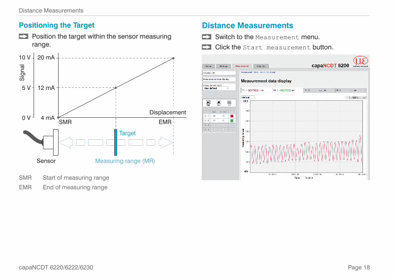
Distance Measurements Switch to the Measurement menu. Click the Start measurement button.
Positioning the Target Position the target within the sensor measuring
range.
20 mA
12 mA
4 mA
Target
Measuring range (MR)Sensor
SMR EMR
10 V
Sig
nal
5 V
0 VDisplacement
SMR Start of measuring rangeEMR End of measuring range

Page 19
Operation and Maintenance
capaNCDT 6220/6222/6230
Operation and MaintenancePlease note for operation and maintenance:
Ensure that the sensor surface is always clean. Before cleaning, turn off the supply voltage. Clean with a damp cloth and then rub the sensor
surface dry.
If the target has been changed or operating periods are very long, minor losses in operating quality are possible. You can correct these long-term errors by recalibrating.
Disconnect the power supply before touching the sensor surface.
> Static discharge, danger of injury
If the cause of a fault cannot be clearly determined, al-ways send the complete measurement system. In case of a defect in the controller, the sensor or the sensor cable, send the affected parts for repair or exchange.
MICRO-EPSILON MESSTECHNIK GmbH & Co. KGKönigbacher Strasse 1594496 Ortenburg / Germany
Tel. +49 (0) 8542 / 168-0 / Fax +49 (0) 8542 / 168-90 [email protected] / www.micro-epsilon.com
Liability for Material DefectsAll components of the device have been checked and tested for functionality at the factory. However, if defects occur despite our careful quality control, MICRO-EPSILON or your dealer must be notified imme-diately.The liability for material defects is 12 months from deliv-ery. Within this period, defective parts, except for wear-ing parts, will be repaired or replaced free of charge, if the device is returned to MICRO-EPSILON with shipping costs prepaid. Any damage that is caused by improper handling, the use of force or by repairs or modifications by third parties is not covered by the liability for material defects. Repairs are carried out exclusively by MICRO-EPSILON.Further claims can not be made. Claims arising from the purchase contract remain unaffected. In particular, MICRO-EPSILON shall not be liable for any consequen-tial, special, indirect or incidental damage. In the interest of further development, MICRO-EPSILON reserves the right to make design changes without notification.For translations into other languages, the German ver-sion shall prevail.

MICRO-EPSILON MESSTECHNIK GmbH & Co. KG
Königbacher Str. 15 · 94496 Ortenburg / Germany
Tel. +49 (0) 8542 / 168-0 · Fax +49 (0) 8542 / 168-90
[email protected] · www.micro-epsilon.com
X9691298-A011127MSC
*X9691298-A01*
MICRO-EPSILON MESSTECHNIK


![Amazon S3 · THE NATIONAL COLLEGIATE ATHLETIC ASSOCIATION P.O. Box 6222 Indianapolis, Indiana 46206-6222 317/917-6222 NCAA.org July 2016 [ISSN 1093-3174] Text Prepared By: NCAA Academic](https://img.pdfslide.us/doc/110x75/5f12c67922ba1e0cfa67fdc2/amazon-s3-the-national-collegiate-athletic-association-po-box-6222-indianapolis.jpg)


![MANUAL MANUAL · ii THE NATIONAL COLLEGIATE ATHLETIC ASSOCIATION P.O. Box 6222 Indianapolis, Indiana 46206-6222 317/917-6222 ncaa.org August 2009 [ISSN 1093-3158] Text Prepared By:](https://img.pdfslide.us/doc/110x75/5f3620a88769456cc856de83/manual-manual-ii-the-national-collegiate-athletic-association-po-box-6222-indianapolis.jpg)