Embed Size (px)
Citation preview

E. Cosenza (ed), Eurocode 8 Perspectives from the Italian Standpoint Workshop, 145-158, © 2009 Doppiavoce, Napoli, Italy
CAPACITY MODELS OF BEAM-COLUMN JOINTS: PROVISIONS OF EUROPEAN AND ITALIAN SEISMIC CODES
AND POSSIBLE IMPROVEMENTS
Angelo Masi a, Giuseppe Santarsiero b, Gerardo M. Verderame c, Gaetano Russo d, Enzo Martinelli e, Margherita Pauletta f, Andrea Cortesia g
a DiSGG, University of Basilicata, Potenza, Italy, [email protected] b DiSGG, University of Basilicata, Potenza, Italy, [email protected]
c DAPS, University of Naples Federico II, Napoli, Italy, [email protected] d DICA, University of Udine, Italy, [email protected]
e DICIV, University of Salerno, Fisciano (SA), Italy, [email protected] f DICA, University of Udine, Udine, Italy, [email protected]
g DICA, University of Udine, Udine, Italy, [email protected]
ABSTRACT More reliable assessment procedures of existing RC buildings are currently available, and have been introduced in the Italian and European codes reporting new rules for seismic design and analysis. However, further studies are necessary in order to upgrade such procedures and, specifically, to test the effectiveness of the capacity evaluation methods relevant to beam-column joints. To this purpose, a literature review on the subject and a wide experimental program on exterior beam-column joint specimens were carried out in the framework of the DPC-ReLUIS Project (Research Line 2, Task NODI). Some results are reported in the present paper to highlighting the role of the key behavioural parameters of RC beam-column joints, thus giving useful suggestions on the reliability of current code expressions and on possible improvements.
KEYWORDS Existing buildings, reinforced concrete, beam-column joint, capacity model.
1 INTRODUCTION
In the framework of DPC-ReLUIS 2005-2008 Research Project, a Research Line (RL 2) was devoted to the “Assessment and Reduction of Seismic Vulnerability of RC Existing Buildings”. In this RL, a task was specifically devoted to the “Behaviour and Strengthening of Beam-Column Joints”. In fact, in spite of a more reliable assessment of this type of structures, and simultaneously with the promulgation of new rules for seismic design and analysis in Italy and Europe, further work is necessary to evaluate the effectiveness of the capacity evaluation methods relevant to beam-column joints contained in the codes. To this purpose, the work was firstly devoted to an accurate literature review on the available capacity evaluation methods, pointing out the most appropriate ones to the Italian and European building stock. Then, such capacity models have been applied to test results deriving from experimental programs on beam-column joints reported in the technical literature, highlighting the models able to better predict the experimental results.

A. Masi, G. Santarsiero, G.M. Verderame, G. Russo, E. Martinelli, M. Pauletta, A. Cortesia
146
As for the ReLUIS experimental program, although the total number of tests up to now performed is not so high and is relevant only to exterior joints, some useful indications have been derived on the prediction capability of code expressions. This has been made comparing the real behaviour in beam-column joints detected during experimental tests, with respect to the conventional performances determined strictly applying the codes.
2 OVERVIEW OF CURRENT RESEARCH STATE
2.1 Capacity models A reliable evaluation of strength and deformability of beam-column joints is a crucial aspect in the framework of performance-based design or evaluation of Reinforced Concrete (RC) buildings, as confirmed by recent experimental activities and damage observations from recent earthquakes. Nowadays, a large consensus has not been found on a single joint modeling technique neither in the scientific literature nor in the Codes, in spite of the fact that many research groups worldwide, during the last three decades, performed wide experimental and theoretical studies on this topic to evaluate the cyclic behavior of beam-column joints. As shown by many experimental programs, the failure of joint panels is induced usually by shear or bond flaws. The stress distribution due to flexural and shear forces transferred through the joint produces a wide diagonal crack pattern in the panel leading to a crushing failure of the compressed strut and consequently to strength and stiffness deterioration. The cyclic deterioration of bond performance, on one side, yields to reduced flexural strength and ductility of framing elements (Hakuto et al., 1999; Manfredi et al., 2008), while it yields, on the other, to a noticeable increase in the story drift (Soleimani et al., 1979).
(a) (b) (c)
Figure 1. Mechanisms of shear transfer at an interior beam-column joint: (a) Force from beam and columns acting on joint core; (b) Strut-mechanism; (c) Truss-mechanism; (Paulay et al., 1992).
In Figure 1a the forces acting on an interior beam-column joint panel are reported. The horizontal shear force Vjh is equal to:
' '2 2 1 1 2jh s c c cV C C T V T T V= + + − = + − (1)
because the horizontal equilibrium equation referred to the end section of the beam yields to:

Capacity Models of Beam-Column Joints
147
2 2 2s cC C T+ = (2)
The vertical shear force can be similarly given by an equilibrium equation, but an accurate evaluation can be given by:
bjv jh
c
hV Vh
= (3)
where hb is the beam depth and hc is the column depth. The shear transfer mechanisms allowing for the joint force transfer, after the diagonal cracking of the joint panel, are shown in Figure 1b-c (Paulay et al., 1992). In the first mechanism, named strut-mechanism, the joint shear is concentrated in a single compressed concrete strut. In this case the transverse steel reinforcement provides confinement to the concrete allowing for higher deformability of the strut, but only before steel yielding. In the second mechanism, named truss-mechanism, the portion of the shear force due to the bond stress along the longitudinal steel reinforcement inside the joint is in equilibrium with a truss mechanism given by concrete struts and vertical and horizontal ties corresponding to joint panel reinforcement. The shear capacity is given by the sum of the shear contributions according to these two mechanisms. It is worth noting that if bond deterioration occurs, the shear contribution due to the strut-mechanism increases, while the total shear force acting on the joint panel remains constant. Assuming a full deterioration of the bond capacity between steel bars and concrete, it is:
2 1sC T= − (4)
so that the following equation is given, that is equal to (1):
' ' '2 2 1 1 1 2 1 1 2jh s c c c cV C C T V T T T T V T T V= + + − = − + + + − = + − (5)
A first approach to evaluate the shear capacity of a beam-column joint without transverse reinforcement consists in principal stress limits according to concrete strength. Direct limits on the shear stress, according to (Hakuto et al., 2000) and reported in many International Codes (ACI 352, 2002; AIJ, 1999) are not accurate because they do not account for the vertical axial force in the column. The principal stresses p in the joint panel can be given by Mohr’s Circle assuming uniform normal and transverse stresses, fa e vjh respectively, according to the following equation:
2
2
2 2a a
jhf fp v− ⎛ ⎞= ± +⎜ ⎟
⎝ ⎠ (6)
Equation (6) allows the horizontal joint shear to be evaluated at the first development of diagonal cracking:
11
1 1a ajh t jh c j j
t c
f fv p V k f b hp k f
= + ⇒ = + (7)

A. Masi, G. Santarsiero, G.M. Verderame, G. Russo, E. Martinelli, M. Pauletta, A. Cortesia
148
where the tensile limit stress pt is assumed to be proportional to k1 times the square root of concrete compressive strength, where k1 is empirically evaluated. It is clearly shown in (7) that axial load delays the diagonal cracking in the joint panel. The joint shear causing compressed concrete strut crushing, assuming the compressive limit stress pc to be proportional to k2 times the concrete compressive strength, is equal to:
21
1 1a ajh c jh c j j
c c
f fv p V k f b hp k f
= − ⇒ = − (8)
It is worth noting that a joint failure criterion based on tensile principal stress limit results to be over conservative. In fact the joint panel is able to transfer noticeable shear forces also in a cracked phase due to the diagonal strut mechanism. The joint failure should be in fact always related to the compressed strut crushing. In the case of high axial loads, the compressed strut crushing can be attained before the joint panel cracking (Paulay et al., 1992). The evaluation of the horizontal joint shear determining the compressed strut crushing, according to equation (8), needs the experimental evaluation of k2 coefficient, accounting for the real stress field in the joint, that is complex to be evaluated in cracked phase, for the compressive strength deterioration due to diagonal tensile strains (Collins et al., 1980), and for the detailing of steel bars anchorage, that is a crucial aspect in the case of exterior joints, to guarantee the development of the compressed strut (Priestley, 1996). In the case of interior joints without transverse reinforcement, the values for k1 e k2 (Priestley, 1996) are 0.29 e 0.50, respectively. In the case of exterior joints, the proposed value for k1 according to Priestley depends on the longitudinal bars anchoring details and it is 0.29 if the longitudinal bars are bent at 90° outside the joint or 0.42 if they are anchored inside the joint. In the case of exterior joints with smooth bars the value for k1 equal to 0.20 is suggested (Calvi et al., 2002). In the cited works, deterioration models are provided to account for k1 and k2 variability based on ductility demand. The strength capacity of joints with transverse reinforcement can be evaluated according to the cited model (Paulay et al., 1992). The minimum horizontal and vertical reinforcement requirements (Ajh, Ajv) are herein reported, while details on the complete model and on the simplified assumption on shear partition in the two mechanisms are given in the original paper. In the case of interior joints, it is:
( )0 11.15 1.3 ; 0.5ycoljh s jv jv col
c g yh yv
fNA A A V Nf A f f
λ⎛ ⎞= − ≥ −⎜ ⎟⎜ ⎟⎝ ⎠
(9)
while in the case of exterior joints, it is:
( )10.7 ; 0.5ycoljh s jv jv col
c g yh yv
fNA A A V Nf A f f
β⎛ ⎞
= − ≥ −⎜ ⎟⎜ ⎟⎝ ⎠
(10)
where β = A’s/As is the tensile over compressed beam reinforcement ratio, fc is the concrete
compressive strength, Ncol is the minimum axial load in the column and Ag is the column cross sectional area. Many other models are available in literature (Sarsam et al., 1985; Vollum et al. 1999; Bakir et al., 2002) to evaluate the shear strength as the sum of concrete and steel reinforcement contributions. However, such models are based on experimental calibration, while the model

Capacity Models of Beam-Column Joints
149
according to Paulay is based on force equilibrium. In this respect, even though sometimes these models seem to be more accurate, it is obvious that their reliability depends on the extent and completeness of the experimental database of tests used for their calibration. During last years, many other works proposed different models to evaluate the strength and deformability of beam-column joints. Amongst the well known models, there is the model (Pantazopolou et al., 1992) based on simple equilibrium equations and extended by (Antopoulos et al., 2002) to FRP strengthened joints. Strut-and-tie models (Hwang et al., 1999; Mitra, 2007) are well known also to analyze the joint panels with or without transverse reinforcement. The “Quadruple flexural resistance in reinforced concrete beam-column joints” (Shiohara, 2001) model accounts for the equilibrium of four rigid bodies forming the joint panel. It allows the different failure modes to be determined accounting for bond behavior of reinforcement in exterior or interior joints. Amongst the models accounting for the inelastic cyclic behavior of beam-column joints and those based on experimental calibration of plastic hinges and/or rotational springs, it can be cited the macro-model proposed in (Lowes et al., 2004) to account for the beam-column joint behavior and implemented in the structural code OpenSees. This algorithm is not time-consuming, but it allows to reliably and objectively account for the main mechanisms determining the inelastic cyclic behavior of the joints: namely, anchorage failure of the longitudinal reinforcement both in the columns and beams, shear failure of the joint panel and failure of the shear transfer mechanism at the joint interfaces.
2.2 Experimental results from the scientific literature The mentioned models for the shear capacity of RC joints can be assessed by comparing their theoretical results with the experimental data derived from the scientific literature purposely collected in a wide database. In particular, 87 results of experimental tests have been considered in this database (Table 1): 66 tests were carried out on specimens with stirrups within the joint panel, while the remaining 21 tests deal with unreinforced RC joints. The former ones basically reproduce the behaviour of joints in new seismically designed structures while the latter ones aim at reproducing the response of existing RC members. As far as the loading modality, a large part of the tests were carried out under cyclic conditions.
Table 1. Experimental data collected in the database. Authors No. of tests Authors No. of tests
Chun & Al. (2007) 2 Lee & Ko (2005) 3 Chun & Kim (2004) 2 Pampanin & Al. (2002) 1 Chutarat & Aboutara (2003) 2 Pantelides & Al. (2000) 4 Durrani & Zerbe (1987) 4 Pantelides & Al. (2002) 6 Ehsani & Al. (1987) 5 Parker & Bullman (1997) 12 Ehsani & Alameddine (1991) 6 Salim (2007) 3 Ehsani & Wight (1985) 10 Scott (1996) 12 Hakuto & Al. (2000) 1 Tsonos & Al. (2002) 6 Hwang & Al. (2004) 1 Tsonos (2007) 2 Hwang & Al. (2005) 5
The four diagrams in Figures 2 and 3 point out the comparison between the experimental results in terms of shear strength with respect to the corresponding results derived by applying four of the above mentioned theoretical models. The experimental values of shear strength of the joint panel (VRj
exp) can be directly derived by the ultimate force applied on the beam through simple equilibrium equations.

A. Masi, G. Santarsiero, G.M. Verderame, G. Russo, E. Martinelli, M. Pauletta, A. Cortesia
150
0
500
1000
1500
2000
2500
0 500 1000 1500 2000 2500
VRjexp [kN]
VRj [k
N] -
Paul
ay&
Prie
stle
y
0
500
1000
1500
2000
2500
0 500 1000 1500 2000 2500
VRjexp [kN]
VRj
[kN
] - S
ARS
AM
&PH
ILLI
PS
a) Paulay & Priestly (1992) model b) Sarsam & Phillps (1985) model
Figure 2. Shear capacity of RC joints: comparison of results from models and experimental tests.
0
500
1000
1500
2000
2500
0 500 1000 1500 2000 2500
VRjexp [kN]
VRj [k
N] -
VO
LLUM
& N
EWM
AN
N
0
500
1000
1500
2000
2500
0 500 1000 1500 2000 2500
VRjexp [kN]
VRj [k
N] -
BA
KIR
& B
OD
URO
GLU
a) Vollum & Newmann (1999) model b) Bakir & Boduroglu (2002) model
Figure 3. Shear capacity of RC joints: comparison of results from models and experimental tests.
Figure 2a is devoted to the model by Paulay & Priestley (1992) resulting in generally scattered and often unconservative prediction of the experimental values. On the contrary, the model by Sarsam & Phillips (1986) is generally more conservative, albeit resulting in significant dispersion with respect to the experimental values (Figure 2b). The model by Vollum & Newmann (1999) results in a more precise prediction of the experimental results (Figure 3a), while the model by Bakir & Boduroglu (2002) is generally unconservative, yet highly correlated to the experimental results (Figure 3b).
3 CAPACITY EVALUATION IN SEISMIC CODES
As for the European Code EC8, both for new (CEN, 2004) and existing (CEN, 2005) buildings, the evaluation of the horizontal maximum shear acting in the joint panel (shear demand) can be performed through the following two expressions, respectively for exterior and interior joints:
Capacity Models of Beam-Column Joints
151
CydsRdjhd VfAV −⋅⋅= 1γ (11)
CydssRdjhd VfAAV −⋅+⋅= )( 21γ (12)
where As1 is the area of the beam top reinforcement, As2 is the area of the beam bottom reinforcement, VC is the column shear force, obtained from the analysis in the seismic design situation, γRd is a factor to account for overstrength due to steel strain-hardening and should be not less than 1.2. The EC8 formulation for predicting the joint shear capacity is made up of two separated steps. Firstly, there is an expression to evaluate the compression capacity of the strut that can be recognized in the joint panel under seismic actions and, then, an expression devoted to verify the tensile strength of the joint in order to avoid diagonal cracking. The horizontal shear demand should not exceed a value that could cause the compression failure of the joint:
jcjd
cdjhd hbfV ⋅−≤ 1 ηνη (13)
where η = 0.60 (1-fck/250) for interior joints and η = 0.48 (1-fck/250) for exterior joints, practically meaning that the strength of exterior joints is 0.8 (0.48/0.60) times that one of interior joints (assuming the same joint materials and detailing); νd is the normalised axial force in the column above the joint, fck is given in MPa, hjc is the distance between the extreme layers of column reinforcement, bj is the effective width of the joint. Further, EC8 provides an expression to evaluate the joint transverse reinforcement (left hand term in (14)) needed to avoid the diagonal cracking caused by the achievement of the concrete tensile strength fctd, as follows:
( )
ctdcddctd
jcjjhd
jwj
ywdsh fffhbV
hbfA
−+
⋅≥
⋅⋅
ν
2/ (14)
where, Ash is the total area of the horizontal hoops in the joint, Vjhd is the horizontal joint shear demand, hjw is the distance between top and bottom reinforcement of the beam. The Italian Code IC (Ministry of Infrastructures, 2008) deals separately with joints belonging to new and existing buildings, the former ones being evaluated as in EC8. As for existing buildings, IC contains two expressions devoted to verify beam-column joint without seismic provisions, that is without hoops in the panel (paragraph C8.7.2.5). These expressions allow to calculate the maximum diagonal compression (15) and tensile (16) stresses in the concrete joint core that must be below given values related to the concrete strength fc:
c
g
n
ggnc f
AV
AN
AN 5,0
22
22
≤⎟⎟⎠
⎞⎜⎜⎝
⎛+⎟
⎟⎠
⎞⎜⎜⎝
⎛+=σ (15) ( )MPain 3,0
22
22
ccg
n
ggnt ff
AV
AN
AN
≤⎟⎟⎠
⎞⎜⎜⎝
⎛+⎟
⎟⎠
⎞⎜⎜⎝
⎛−=σ (16)
where N is the axial force acting on the upper column, Ag is the gross area of the joint panel horizontal section and Vn the horizontal shear acting in the joint panel evaluated accounting both the column shear and the shear transmitted by the beam reinforcing bars.

A. Masi, G. Santarsiero, G.M. Verderame, G. Russo, E. Martinelli, M. Pauletta, A. Cortesia
152
4 CRITICAL REVIEW OF CODE PROVISIONS
Results about joint behaviour, obtained principally from the experimental tests carried out during the ReLUIS project, provided some useful information to critically review and analyse some expressions reported in the European Code EC8 and in the Italian Code IC.
4.1 Evaluation of the shear demand Vjhd Expressions (11) and (12), regarding exterior and interior joints, respectively, may underestimate the shear demand that the beam can really transmit to the joint. Indeed, the amplified tension that appears in the expressions, γRd·fyd , is a design value that the steel certainly exceeds when the plastic hinge develops in the beam. By considering that: (i) the real yielding strength fy usually exceeds the nominal yielding strength fyk, even though
it should not exceed over the 25% (EC8 par. 5.5.1.1(3)P and IC Tab. 11.3.Ib), and (ii) the characteristic value of the ratio between the ultimate strength ft and the yielding
strength fy must be in the range 1.15-1.35, it can be considered that steel bars, in case of large strains, can reach, on the average, a tension value up to ftm =1.45 fyk, instead of the value suggested by EC8 and IC that is equal to 1.04 fyk achieved by multiplying fyk by γRd =1.20 and dividing by γs = 1.15. An experimental proof of that statement has been obtained for the exterior joints tested by the Research Unit (RU) of University of Udine (Russo et al., 2007 and 2008) during the ReLUIS project, where the shear demand was calculated through the expression (11) using:
2/)25.11(1 ,
+⋅== meany
SS
ykyd
fff
γγ (17)
since only the mean value fy,mean of reinforcing steel was available and the characteristic value fyk = fy,nom was unknown. The values of Vjhd calculated as described above and the maximum ones obtained by experimental results, Vexp, are significantly different, as shown in Table 2.
Table 2. Calculated (Vjhd) and measured (Vexp) shear values.
Joint Vjhd (kN) Vexp (kN) 12-6 (+) 50.4 99.3 12-6 (-) 49.6 103.2 12-8 (+) 50.7 97.6 12-8 (-) 48.7 110.0 16-6 (+) 49.0 108.4 16-6 (-) 90.6 147.2 16-8 (+) 52.1 108.9 16-8 (-) 88.5 162.2
(+) positive acting moment (-) negative acting moment The Vexp values shown in Table 2 have been determined using the expression (11) where γRd As1 fyd has been substituted by the actual force value provided by the reinforcing bars. This value is obtained by dividing the maximum experimental moment at the beam-column interface by 0,9db, with db the effective depth of the beam. Further, Vc is the maximum shear in the column corresponding to the maximum experimental beam moment. From the above considerations and on the basis of the results shown in Table 2, it can be deduced that the expressions (13) and (14) (either 5.33 and 5.35 of EC8 or 7.4.8 and 7.4.10 of

Capacity Models of Beam-Column Joints
153
IC) for resistance verification (maximum diagonal compression and tension in concrete core) of joints with or without hoops can be not conservative, being the acting shear Vjhd (Eq.(11)) underestimated. In addition, the calculation of demand in EC8 for joints of existing buildings is the same as for new buildings applying the equations (11) and (12), with the difference that, as reported in (CEN, 2005), the mean values of material resistance must be divided by the Confidence Factor (CF) and, in case of brittle elements as the beam-column joints are, by the partial factor γs. This can lead to a greater underestimation (with respect to the joints of new buildings) of the shear demand, using a very low tension in beam reinforcing bars equal to:
s
ymRdyd CF
ff
γγ
⋅⋅= (18)
where fym is the mean value of the yielding strength of steel. Use of CF in expression (18) does not appear correct, as it should provide lower values of fyd to be used in equations (11) and (12), thus lower demand values on joints at decreasing knowledge levels. It is then advisable, as typically suggested when strength values need to be used in calculating action effects delivered to brittle component/mechanism by ductile components, that mean values of material properties are multiplied and not divided by CF in order to appropriately account for the attained knowledge level. Moreover, the safety factor γs should be assumed equal to 1.0, thus expression (18) can be effectively rewritten as follows:
ymrdyd fCFf ⋅⋅= γ (19)
where the term CFRd ⋅γ could be limited to the value of 1.45 taking into account what above reported real yielding and ultimate strength values.
5 ANALYSIS OF PREDICTION ABILITY OF CODE FORMULATIONS THROUGH ReLUIS EXPERIMENTAL TESTS
In order to verify the estimation capability of the joint shear strength provided by the expressions contained in IC and EC8, they have been applied to the specimens tested at Laboratory of Structures of the University of Basilicata (UniBas RU) in the framework of the DPC-Reluis Project. During the experimental program, 10 quasi-static cyclic tests on exterior full scale beam-column joints, provided with different Earthquake Resistant Design (ERD) Level, axial force values and type of steel reinforcement, have been carried out. The main characteristics of the specimens under test and of the obtained results are summarized in Table 3. The specimens had three different ERD levels: design for seismic zone 2 (Z2), for seismic zone 4 (Z4) and with respect to gravity loads only (NE). The normalized axial load applied during test was equal either to 0.15 (NL) or 0.30 (NH). More details on the experimental program are reported in (Masi et al., 2008), (Masi et al., 2008b) and in (Masi & Santarsiero, 2008). As it can seen in Table 3, 7 out of 10 specimens showed a failure mechanism that involved only the beams because of their small amount of longitudinal reinforcement, particularly the bottom one. Adopting the expressions (13)-(16), joint strength values (compression and tension capacities) have been determined for each of the 10 tested joints accounting for amount of transverse reinforcement, axial force value, concrete and steel strengths. No

A. Masi, G. Santarsiero, G.M. Verderame, G. Russo, E. Martinelli, M. Pauletta, A. Cortesia
154
conventional safety factors have been taken into account. Further, mean values of material strengths have been considered, thus fck has been assumed equal to fcm=21 MPa (achieved as the mean value from compression tests on cube specimens purposely tested during the experimental program), as well as fctd has been assumed equal to fctm=2.28 MPa. The tension value exhibited by reinforcing bars has been determined for each tested specimen imposing the equilibrium of the sub-assemblage under the maximum applied horizontal force. Therefore, for each joint a different value of steel strength has been determined according with the variability of the material characteristics and the amount of the slippage effects, as reported in Table 4. In Table 3 the failure mode is indicated as “B” in the cases in which the specimen showed a flexural failure in the beam, while “J” indicates the occurrence of a diagonal cracking in the joint panel. As it can be seen, joint cracking is always accompanied by flexural cracking and yielding of beam longitudinal reinforcement.
Table 3. Main results from UniBas experimental tests.
Test # Design type
Axial load
Failure mode
Maximum column shear (kN)
Collapse drift (%)
T1 NE NL B 18.9 2.75 T2 Z2 NH B 40.2 3.36 T3 Z2 NH B 38.9 4.96 T4 Z4 NH B 42.9 3.45 T5 Z2 NL J+B 39.8 3.25 T6 NE NH B 21.3 2.85 T7 NE NL B 21.3 3.28 T8 Z4 NH B 42.8 3.40 T9* Z2 NH J+B 48.3 3.30
T10* Z2 NL J+B 48.9 3.65 *specimens with reinforcing bars having higher strength and lower deformation capacity
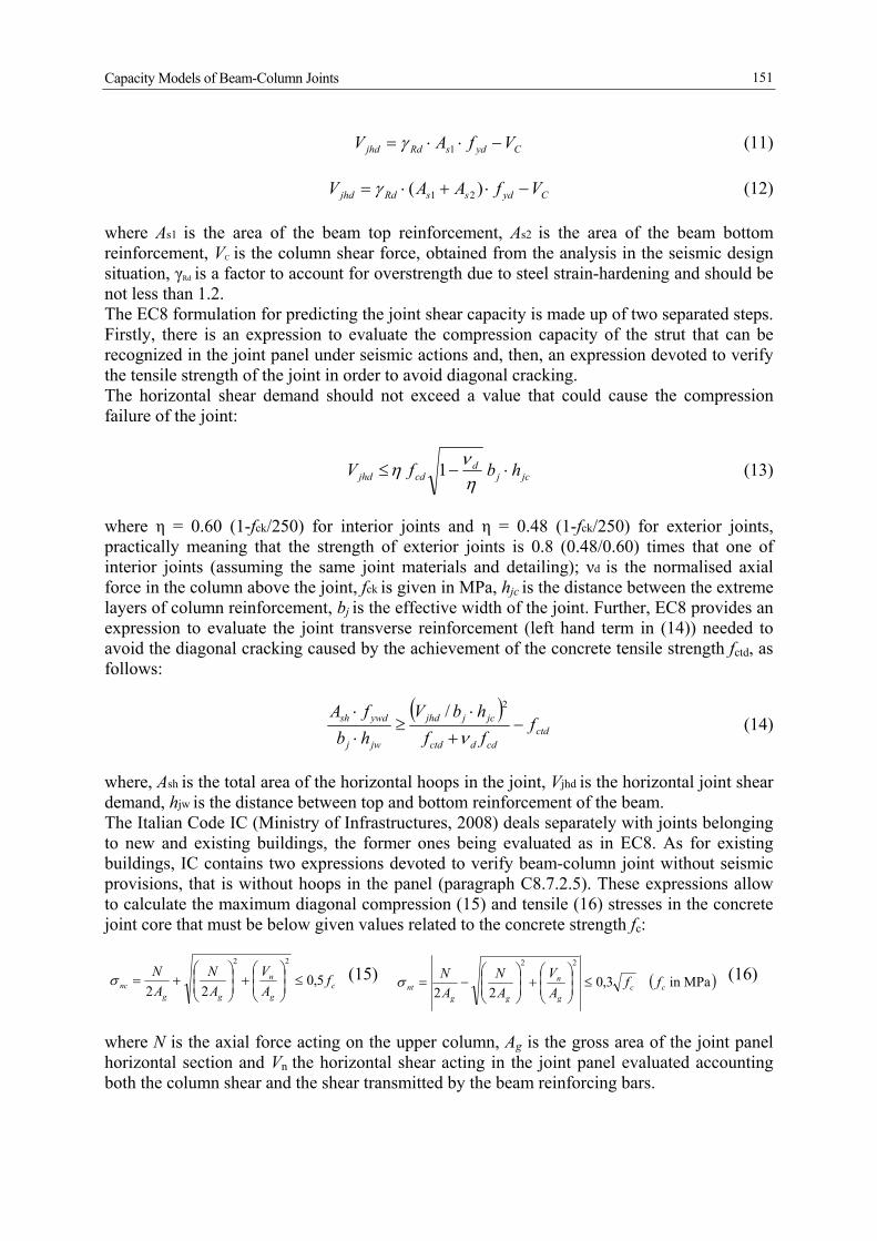
In Figure 4, as an example, the force-drift relationships and the damage pattern occurred to the specimens during the tests T3 and T5 are shown. The specimen of test T3 shows no cracks in the joint panel and all the damage is concentrated at the beam-column interface with a depth flexural crack. Collapse of this joint was caused by the tensile failure of the bottom longitudinal bars in the beam. The specimen of the test T5, identical to the previous one, showed a heavy damage into the joint panel in addition to the flexural cracks in the beam. The different behaviour is attributable to the value of the axial force acting in the column that was lower in the test T5. The occurrence of the joint failure caused less satisfactory performance, as displayed in Figure 4: test T5 shows greater stiffness and strength deterioration as well as more pronounced pinching of hysteresis loops. Results of the application of code formulations reported at the paragraph 3 for estimating the joint shear capacity, are shown in Figure 5. Design strength value of steel bars are evaluated assuming CF, γs and γRd equal to 1.0. For each test, the first (blue) bar is relevant to the joint shear Vexp experimentally determined, that is by using expression (11) as already explained at par. 4.1. For each of 10 tests both compression strength Vjc and tensile strength Vjt have been evaluated through the code expressions (13) and (14), and, only for NE joints, also applying IC code expressions (15) and (16) for existing buildings. Results in Figure 5a show that the shear strengths provided by code expressions are greater than Vexp, except for the tests T5, T9 and T10. In particular, tests T5 and T10 show a predicted tensile strength Vjt lower than the experimental shear Vexp in agreement to the

Capacity Models of Beam-Column Joints
155
observed failure modality of the joints that involved both the beam and the joint panel (see Table 3). As for test T9, it can be observed that the predicted compressive strength Vjc is lower than the experimental joint shear Vexp, highlighting the occurrence of a compression failure of the joint panel. The EC8 expressions are, in these cases, able to predict the joint shear failure.
T3 t
est
T5 t
est
Figure 4. Examples of mechanical behaviour and damage state (UniBas experimental program).
0
100
200
300
400
500
600
700
800
900
T2 T3 T4 T5 T8 T9 T10
Join
t She
ar (k
N)
VexpVjc (Eq.3.3)Vjt (Eq.3.4)
0
100
200
300
400
500
600
700
800
900
T1 T6 T7
Join
t She
ar (k
N)
VexpVjc (Eq.3.3)Vjt (Eq.3.4)Vjc (Eq.3.5)Vjt (Eq.3.6)
Figure 5. Comparison between experimental and analytical joint shear strength values: a) specimens with
seismic design, b) specimens w/o seismic design (UniBas experimental program).
The diagram in Figure 5b shows also the values of the joint shear strength obtained applying expressions (15) and (16) provided in IC to verify joints without transverse reinforcement belonging to existing buildings, thus applicable only to NE joints. In this case Vjt and Vjc (green and yellow bars) are always greater than Vexp in accordance with the experimental result, although it cannot be stated whether the expressions (15) and (16) would be able to predict joint failure. As for the estimation of the shear demand, in Table 4 a comparison between the shear values experienced by the joints during the tests Vexp and the shear demand Vjhd calculated according to the code expression (11), is reported. As can be seen, the “real” shear demand values are
a) b)

A. Masi, G. Santarsiero, G.M. Verderame, G. Russo, E. Martinelli, M. Pauletta, A. Cortesia
156
always higher than the theoretical ones: Vexp > Vjhd. It is worth specifying that Vjhd has been calculated blindly applying EC8, referring to the design yield strength of reinforcing bars used to build the specimens, that is fyd = fyk /γs = 430/1.15 = 373.9 MPa, where fyk is the nominal yield strength. The mean value of the ratio Vexp/Vjhd is about 1.26, highlighting the need of a correction of the strength value to be used in calculating the shear demand, as already pointed out at par. 4.1, in order to avoid a remarkable underestimation of the joint shear demand. Finally, the estimated steel strength, showed in Table 4, has a mean value 1.24 times the nominal yield stress fyk and 1.08 times the mean value of yield stress fy deduced by tensile tests performed on bars actually used to build the specimens.
Table 4. Comparison between experimental and code shear in joints tested at UniBas.
Test N. Vjhd [kN] Vexp [kN] Estimated steel strength (MPa)
T1 82.6 103.8 542.4 T2 230.3 264.8 505.9 T3 231.7 282.0 532.1 T4 196.6 235.6 521.6 T5 230.7 267.9 510.4 T6 80.1 103.3 551.1 T7 80.1 104.6 557.0 T8 196.7 248.5 545.6 T9 222.2 303.2 582.9 T10 221.7 322.5 615.9
6 FINAL REMARKS AND IMPROVEMENT PROPOSALS
The main objective of the present paper was to investigate on the experimental behaviour of RC beam-column joints, thus providing a contribution to a more reliable evaluation of the seismic vulnerability of RC existing buildings. In particular, the understanding and the validation of capacity models reported in the current seismic codes is of great interest. To this purpose, a wide bibliographic research on available capacity models and experimental investigations on beam-column joints have been firstly carried out. Literature analysis has been devoted to carefully describe some capacity evaluation models and to compare their prediction ability applying them to a database of experimental results. The capacity model of Vollum & Newmann (1999) appeared more effective in predicting shear capacity of the analysed joints. Use of this model could be suggested to improve the code expressions on joint shear strength, although further work needs to be made in order to enlarge the database of analysed experimental results. The validation of the code expressions (reported in EC8 and IC) has been made on the basis of the ReLUIS project results. The main result is that the shear demand computed by using code expression (11) can be unconservative if a suitable value of the steel strength is not assumed. Experimental programs performed by University of Basilicata and Udine RUs demonstrated that the actual shear demand in joints is always greater than the theoretical one, being the difference dependent on steel type and bond conditions. Specifically, for existing buildings the underestimation of shear demand can be greater with respect to joints belonging to new buildings because, strictly applying the current code provisions, the estimated steel strength should be divided also by the confidence factor (CF). A more suitable application of code expressions is proposed in the present paper where mean values of material properties are multiplied by CF, as typically suggested when strength values need to be used in

Capacity Models of Beam-Column Joints
157
calculating action effects delivered to brittle component/mechanism by ductile components. Further, the actual stress values exhibited by the steel during the tests were calculated and used for safety verifications using code expressions (13) and (14) for joint shear capacity. As a result, the code capacity models appeared able to predict whether or not the joint cracking occurred, provided that the right steel strength values were used. Due to the limited amount of tested specimens, further work is required to get a more reliable proof of the effectiveness of code expressions, skilfully combining purposely designed experimental investigations, review of experimental campaigns reported in the literature, and accurate numerical simulations. Particularly, extensive experimental programs on joint specimens having different characteristics (e.g. interior or exterior, bi- or tri-dimensional, beam type, etc.) well targeted on the types representative of the Italian and European built environment, need to be performed.
7 ACKNOWLEDGEMENTS
This work has been carried out under the program “Dipartimento di Protezione Civile-Consorzio RELUIS”, signed on 2005-07-11 (n. 540), Research Line 2, whose financial support was greatly appreciated.
8 REFERENCES
ACI - American Concrete Institute (2002), Recommendations for design of beam-connections in monolithic reinforced concrete structures, ACI352R-02, Farmington Hills, Michigan.
AIJ - Architectural Institute of Japan (1999), Design guideline for earthquake resistant reinforced concrete buildings based on inelastic displacement concept, Tokyo, Japan.
Antonopoulos C. P. and Triantafillou T. C. (2002), Analysis of FRP-strengthened RC beam-column joints, ASCE Journal of Composites for Construction, Vol. 6, No. 1, 41-51.
Bakir P.G. and Boduroglu H. M. (2002), A new design equation for predicting the joint shear strength of monotically loaded exterior beam-column joints, Engineering Structures Vol. 24, No. 8, 1105-1117.
Calvi G. M., Magenes G. and Pampanin S. (2002), Relevance of beam-column joint damage and collapse in RC frame assessment, Journal of Earthquake Engineering, Vol. 6, Special Issue 1, 75-100.
CEN (2004). EN 1998-1:2004 Eurocode 2 - Design of concrete structures - Part 1: General rules and rules for buildings.
CEN (2005). EN 1998-3:2005 Eurocode 8: Design of structures for earthquake resistance - Part 3: Assessment and retrofitting of buildings.
Collins M. P. and Mitchell D. (1980), Shear and torsion design of prestressed and nonprestressed concrete beams, Journal of the Prestressed Concrete Institute, Vol. 25, No. 5, 32-101.
Hakuto S., Park R. and Tanaka H. (2000), Seismic load tests on interior and exterior beam-column joints with substandard reinforcing details, Vol. 97, No. 1, 11-25.
Hakuto S., Park R., and Tanaka H. (1999), Effect of deterioration of bond of beam bars passing through interior beam-column joints on flexural strength and ductility, ACI Structural Journal; Vol. 96, No.5, 858-864.
Hwang S. J. and Lee H. J. (1999), Analytical model for predicting shear strengths of exterior reinforced concrete beam-column joints for seismic resistance, ACI Structural Journal, Vol. 96, No. 5, 846-858.
Lowes L., Mitra N. and Altoontash A. (2004), A beam-column joint model for simulating the earthquake response of reinforced concrete frames, Pacific Earthquake Engineering Research Center, PEER 2003/10.

A. Masi, G. Santarsiero, G.M. Verderame, G. Russo, E. Martinelli, M. Pauletta, A. Cortesia
158
Manfredi G., Verderame G. M. and Lignola G. P. (2008), A F.E.M. model for the evaluation of the seismic behavior of internal joints in reinforced concrete frames, The 14th World Conference on Earthquake Engineering; October 12-17, 2008, Beijing, China (paper ID: 05-01-0189).
Manfredi G., Verderame G.M. Lignola G.P. (2008), A F.E.M. model for the evaluation of the seismic behavior of internal joints in reinforced concrete frames, The 14th World Conference on Earthquake Engineering, October 12-17, 2008, Beijing, China.
Masi A., Santarsiero G. (2008), Sperimentazione su nodi trave-colonna in c.a. progettati con diversi livelli di protezione sismica: primi risultati, Proc. Reluis2Rm08 “Valutazione e riduzione della vulnerabilità sismica di edifici esistenti in c.a.”, Roma, 29-30 maggio, E. Cosenza, G. Manfredi, G. Monti Eds., Polimetrica International Scientific Publisher, ISBN 978-88-7699-129-5.
Masi A., Santarsiero G., Dolce M., Moroni C., Nigro D. (2008), Il programma sperimentale su nodi trave-colonna in c.a. in corso all’Università di Basilicata, Proc. Reluis2Rm08 “Valutazione e riduzione della vulnerabilità sismica di edifici esistenti in c.a.”, Roma, 29-30 maggio, E. Cosenza, G. Manfredi, G. Monti Eds., Polimetrica International Scientific Publisher, ISBN 978-88-7699-129-5.
Masi A., Santarsiero G., Moroni C., Nigro D., Dolce M., Russo G., Pauletta M., Realfonzo R., Faella C., Lignola G.P., Manfredi G., Prota A., Verderame G.M. (2008b), Behaviour and strengthening of RC beam-column joints: experimental program and first results of the research activity in the framework of Dpc-Reluis project (Research Line 2), The 14th World Conference on Earthquake Engineering October 12-17, 2008, Beijing, China.
Ministero delle Infrastrutture (2008). DM 14 gennaio 2008, Norme tecniche per le costruzioni, Suppl. or. n.30 alla G.U. n.29 del 4/2/2008 (in Italian).
Ministero delle Infrastrutture (2009). Circolare 2 febbraio 2009, Istruzioni per l’applicazione delle “Nuove norme tecniche per le costruzioni”, Suppl. or. n.27 alla G.U. n.47 del 26/2/2009 (in Italian).
Mitra N. (2007), An analytical study of reinforced concrete beam-column joint behaviour under seismic loading, University of Washington, PhD Thesis.
Pantazopoulou S. and Bonacci J. (1992), Consideration of question about beam-column joints, ACI Structural Journal, Vol. 89 No. 1, 27-36.
Paulay, T. and Priestley M.J.N. (1992), Seismic design of reinforced concrete and mansory buildings, New York: John Wiley and Sons.
Priestley M. J. N. (1996), Displacement-based seismic assessment of reinforced concrete buildings, Journal of Earthquake Engineering, Vol. 1, No. 1, 157-192.
Russo, G., Pauletta, M. (2008). Comportamento di Nodi Trave-Pilastro Esterni Rinforzati, Proc. Reluis2Rm08 “Valutazione e riduzione della vulnerabilità sismica di edifici esistenti in c.a.”, Roma. 29-30 maggio, E. Cosenza, G. Manfredi, G. Monti Eds., Polimetrica International Scientific Publisher, ISBN 978-88-7699-129-5, pp.561-568.
Russo, G., Pauletta, M., e Nardi, E. (2007). Indagine Sperimentale su Nodi Esterni Trave-PilastroArmati con Barre Lisce. Atti del XII Convegno ANIDIS “L’ingegneria Sismica in Italia”, 10-14 giugno 2007, Pisa, Italia.
Sarsam K. F. and Phillips M. E. (1985), The shear design of in situ reinforced beam-column joints subjected to monotonic loading, Magazine of Concrete Research Vol. 37, No. 130, 16-28.
Shin M., LaFave J. M. (2004), Modelling of cyclic joint shear deformation contributions in RC beam-column connections to overall frame behaviour, Structural Engineering and Mechanics; Vol 18, No.5 645-669
Shiohara H. (2001), A New Model For Joint Shear Failure of Reinforced Concrete Interior Beam-to-Column Connections, ASCE Journal of the Structural of Engineering, Vol. 127, No. 2, 152-160.
Soleimani D., Popov E. P. and Bertero V. V. (1979), Hysteretic behavior of reinforced concrete beam-column subassemblages, ACI Journal; Vol. 76, No.11, 1179-1195.
Vollum R. L. and Newman J. B. (1999), The design of external reinforced concrete beam-column joints, The Structural Engineer, Vol. 77, No. 23 & 24, 21-27.