Embed Size (px)
Citation preview
1
CAPACITY DESIGN CRITERIA FOR SEISMIC RESISTANCE OF
PRECAST CONCRETE COLUMNS USING STEEL BOX
CONNECTION
*Chayanon Hansapinyo, Nutchanon Siri and Chinnapat Buachart
Center of Excellence for Natural Disaster Management, Department of Civil Engineering,
Chiang Mai University, Thailand
*Corresponding Author, Received: 30 June 2017, Revised: 19 Nov. 2017, Accepted: 20 Dec. 2017
ABSTRACT: A variety of advantages of precast concrete adding to benefits of concrete has made the pre-
fabrication and assembly systems widely adopted in building construction business. However, the
connections may diminish the increase in the utilization due to their complication in the installation work and
seismic design consideration. This paper presents an easy-to-install steel box for column base connection
designed based on the standard capacity design criteria. Experimental investigations on the precast concrete
columns using the steel box connection at the column base under cyclic loading were also made. The test
results show the satisfactory seismic performance of the precast specimens both in seismic shear capacity,
ductility and energy dissipation compared with the identical cast-in-place specimen. The failure of the precast
columns, with proper details, was in the flexural ductile mode. The shear capacity was respectively 1.16-1.24
times higher than the averaged capacity of the cast-in-place column. The damping ratio was about 18-25
percent in the inelastic range, after the drift ratio of 3.0%. Finally, the seismic performance of the designed
precast concrete column using the steel box connection based on the capacity design criteria is guaranteed
without early brittle failures.
Keywords: Precast concrete column, Seismic design, Column steel box connection, Lateral cyclic load
1. INTRODUCTION
The exposure of buildings to damage from
seismic shaking is steadily increasing because of
continuing urbanization. However, a significant
reduction of the risk can be accomplished through
improved building codes and construction qualities.
For the design of buildings in a seismic prone area,
failure mechanism of structural elements in a
building must be considered to ensure ductile
damage under a severe earthquake. Columns and
beam-column joint are maintained in the elastic
range. In other words, a good structure must be
able to control the failure mode and location of
damage. Under a big earthquake, flexural failure
induced by yielding of the longitudinal
reinforcement is expected to localize on beam
elements for absorbing and dissipating energy.
This phenomenon can be achieved by a systematic
design for the Weak Beam-Strong Column failure
mechanism using the Capacity Design criteria [1].
Following this concept, the Beam sideway
mechanism (Fig.1(a)) is permitted for the failure
mechanism of frame buildings under a severe
earthquake load. Experience of past strong
earthquakes has proved considerable fewer losses
of the Beam sideways buildings compared with the
Column sideways buildings (Fig.1(b)).
As the column and the beam-column joint
elements are very important for the frame building,
many past researchers investigated the shear
capacity demand of the elements under the lateral
loading [2-5]. The column capacity models based
on key parameters were developed [6,7]. For the
precast column with the base connection, Rejame
et al [8] conducted an experimental investigation
on precast columns in socket foundations with
internal smooth interfaces. The tested specimens
were failed by the yielding of the longitudinal
reinforcement out of the embedded region.
Seismic design of ductile reinforced concrete
frames has been developed over a long period of
time. A successful design method has been based
on the past lessons learned from the failed
buildings. However, the design of precast concrete
element has been done based mainly on
information of the experimental result of a
prototype element, as a wide variety of precast
connection options. As a result, innovation
integrated with fabricator capabilities is the key to
create a successful solution. This paper presents
lateral cyclic load test and seismic design of
precast concrete columns using steel box
connection. The connection was adapted from the
column-to-foundation connection with bolted
socket presented by Negro, and Toniolo [9]. The
technique permits faster construction with the use
of this bolted connection type, as shown in Fig. 2.
International Journal of GEOMATE, May, 2018 Vol.14, Issue 45, pp.1-9
Geotec., Const. Mat. & Env., DOI: https://doi.org/10.21660/2018.45.7360 ISSN: 2186-2982 (Print), 2186-2990 (Online), Japan
International Journal of GEOMATE, May, 2018 Vol.14, Issue 45, pp.1-9
2
Seismic design of concrete frame buildings is first
described to overview demand capacity for the
design of the precast concrete columns. Following
the strength-based design concept or the Capacity
Design method, a ductile emulative design can be
achieved maintaining the elastic performance of
the connection part (Fig.2(c)) [10]. Then, precast
concrete columns with the steel box connection, as
shown in Fig.2(b) and identical cast-in-pace
concrete column tests under lateral cyclic load is
explained. From the test, seismic performance of
the precast columns is discussed compared with
the cast-in-place one. Eventually, the design of the
precast columns and the steel box connection are
described based on the test results.
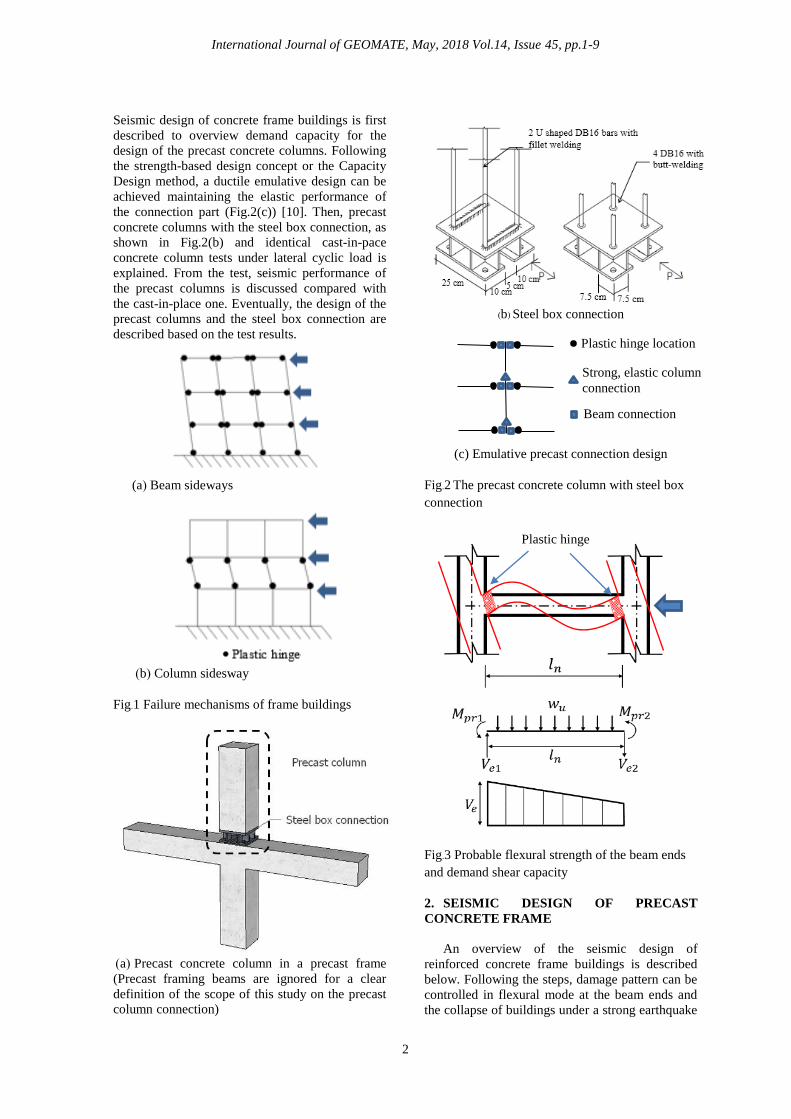
(a) Beam sideways
(b) Column sidesway
Fig.1 Failure mechanisms of frame buildings
(a) Precast concrete column in a precast frame
(Precast framing beams are ignored for a clear
definition of the scope of this study on the precast
column connection)
(b) Steel box connection
(c) Emulative precast connection design
Fig.2 The precast concrete column with steel box
connection
Fig.3 Probable flexural strength of the beam ends
and demand shear capacity
2. SEISMIC DESIGN OF PRECAST
CONCRETE FRAME
An overview of the seismic design of
reinforced concrete frame buildings is described
below. Following the steps, damage pattern can be
controlled in flexural mode at the beam ends and
the collapse of buildings under a strong earthquake
Plastic hinge
Plastic hinge location
Strong, elastic column
connection
Beam connection
International Journal of GEOMATE, May, 2018 Vol.14, Issue 45, pp.1-9
3
can be avoided based on the Capacity Design
criteria.
2.1 Estimation of Seismic Load
First, for a regular building, the lateral seismic
load on the building is estimated according to a
local standard. The load depends on seismic
parameters including local seismic intensity, type
of building, type of soil, building weight and
dynamic properties. The calculation starts with
base shear force estimation and then distributes the
force to each floor of the building. Structural
analysis of the building is next performed for the
element forces induced by all cases of load
combination.
2.2 Design of Frame Beam and Capacity
Demand
From the envelope flexural force of the
building analysis, flexural strengths required for
beams are obtained and required longitudinal
reinforcement can be determined accordingly. The
provided beam reinforcement is used for the
capacity demand to avoid undesirable damage
under a strong earthquake by forming the flexural
hinge at the beam ends. The demand shear force
(e
V ) at the stage is estimated as shown in Eq.(1)
and Fig.3. The beam shear capacity designed
following this procedure ensures the avoiding of
shear failure in the beam element.
2
21 nu
n
prpr
e
lw
l
MMV
(1)
where
1prM and
2prM are the probable flexural
strength of the beam ends
uw is the factored load/length of the beam
nl is the clear length of the beam
2.3 Design of Frame Column and Beam-Column
Joint
To protect the columns against a strong
earthquake, design shear and flexural strengths of
the columns must be higher than the flexural
strength of the joining beams. Kuntz and
Browning [11] have shown that the failure
mechanism as shown in Fig.1(a) can only be
achieved if the column-to-beam ratio is relatively
large (on the order of four). According to ACI318
[12], the flexural strengths of the columns shall
satisfy
nbnc
MM 2.1 (2)
where
ncM is the sum of nominal flexural
strengths of columns framing into the joint
nbM is the sum of nominal flexural
strengths of beams framing into the joint
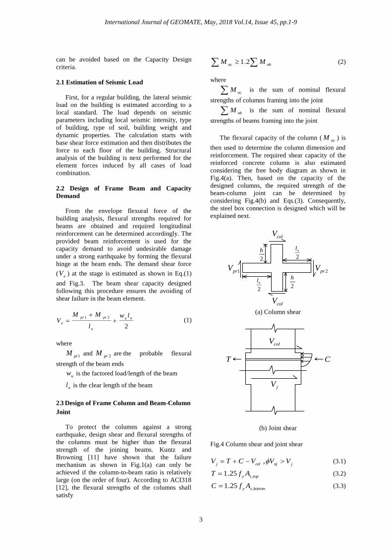
The flexural capacity of the column (nc
M ) is
then used to determine the column dimension and
reinforcement. The required shear capacity of the
reinforced concrete column is also estimated
considering the free body diagram as shown in
Fig.4(a). Then, based on the capacity of the
designed columns, the required strength of the
beam-column joint can be determined by
considering Fig.4(b) and Eqs.(3). Consequently,
the steel box connection is designed which will be
explained next.
(a) Column shear
colV
jV
T C
(b) Joint shear
Fig.4 Column shear and joint shear
coljVCTV
jnjVV , (3.1)
topsyAfT
,25.1 (3.2)
bottomsyAfC
,25.1 (3.3)
colV
colV
1prV 2prV
2
h
2
h
2
nl
2
nl
International Journal of GEOMATE, May, 2018 Vol.14, Issue 45, pp.1-9
4
where
1prV ,
2prV are the shear capacity of the
framing beams calculated based on the maximum
probable flexural strength of the beams
colV is the column joint shear considering the
force equilibrium in Fig.4(a)
jV is the joint shear
njV is the reduced joint shear capacity [12]
T and C are respectively the maximum tension
and compression of the left and right joining beam
topsA
, and
bottomsA
,are the top and bottom
longitudinal reinforcement area, respectively
yf is the yielding strength of the
reinforcement
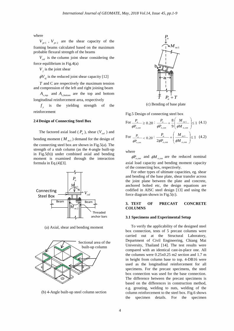
2.4 Design of Connecting Steel Box
The factored axial load (u
P ), shear (col
V ) and
bending moment (1nc
M ) demand for the design of
the connecting steel box are shown in Fig.5(a). The
strength of a stub column (as the 4-angle built-up
in Fig.5(b)) under combined axial and bending
moment is examined through the interaction
formula in Eq.(4)[3].
(a) Axial, shear and bending moment
(b) 4-Angle built-up steel column section
(c) Bending of base plate
Fig.5 Design of connecting steel box
For 20.0
,
conn
u
P
P
: 1
9
8
,
1
,
conn
nc
conn
u
M
M
P
P
(4.1)
For 20.0
,
conn
u
P
P
: 1
2,
1
,
conn
nc
conn
u
M
M
P
P
(4.2)
where
connP
, and
connM
, are the reduced nominal
axial load capacity and bending moment capacity
of the connecting box, respectively.
For other types of ultimate capacities, eg. shear
and bending of the base plate, shear transfer across
the joint plane between the plate and concrete,
anchored bolted etc, the design equations are
codified in AISC steel design [13] and using the
force diagram shown in Fig.5(c).
3. TEST OF PRECAST CONCRETE
COLUMNS
3.1 Specimens and Experimental Setup
To verify the applicability of the designed steel
box connection, tests of 5 precast columns were
carried out at the Structural Laboratory,
Department of Civil Engineering, Chiang Mai
University, Thailand [14]. The test results were
compared with an identical cast-in-place one. All
the columns were 0.25x0.25 m2 section and 1.7 m
in height from column base to top. 4-DB16 were
used as the longitudinal reinforcement for all
specimens. For the precast specimens, the steel
box connection was used for the base connection.
The difference between the precast specimens is
based on the differences in construction method,
e.g. grouting, welding to nuts, welding of the
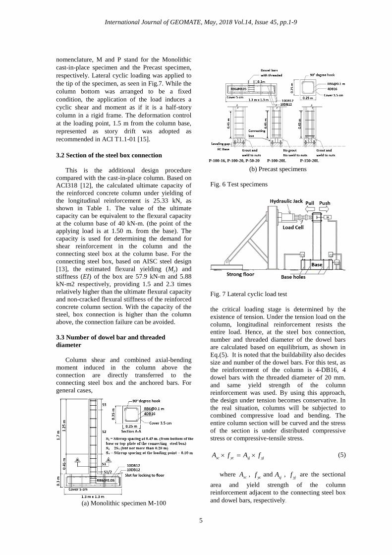
column reinforcement to the steel box. Fig.6 shows
the specimen details. For the specimen
Connecting Steel Box
Beam Beam
Threaded anchor bars
uP
1ncM
2ncM
colV
a
b
uP
1ncM
T TPu
Sectional area of the
built-up column
International Journal of GEOMATE, May, 2018 Vol.14, Issue 45, pp.1-9
5
nomenclature, M and P stand for the Monolithic
cast-in-place specimen and the Precast specimen,
respectively. Lateral cyclic loading was applied to
the tip of the specimen, as seen in Fig.7. While the
column bottom was arranged to be a fixed
condition, the application of the load induces a
cyclic shear and moment as if it is a half-story
column in a rigid frame. The deformation control
at the loading point, 1.5 m from the column base,
represented as story drift was adopted as
recommended in ACI T1.1-01 [15].
3.2 Section of the steel box connection
This is the additional design procedure
compared with the cast-in-place column. Based on
ACI318 [12], the calculated ultimate capacity of
the reinforced concrete column under yielding of
the longitudinal reinforcement is 25.33 kN, as
shown in Table 1. The value of the ultimate
capacity can be equivalent to the flexural capacity
at the column base of 40 kN-m. (the point of the
applying load is at 1.50 m. from the base). The
capacity is used for determining the demand for
shear reinforcement in the column and the
connecting steel box at the column base. For the
connecting steel box, based on AISC steel design
[13], the estimated flexural yielding (My) and
stiffness (EI) of the box are 57.9 kN-m and 5.88
kN-m2 respectively, providing 1.5 and 2.3 times
relatively higher than the ultimate flexural capacity
and non-cracked flexural stiffness of the reinforced
concrete column section. With the capacity of the
steel, box connection is higher than the column
above, the connection failure can be avoided.
3.3 Number of dowel bar and threaded
diameter
Column shear and combined axial-bending
moment induced in the column above the
connection are directly transferred to the
connecting steel box and the anchored bars. For
general cases,
(a) Monolithic specimen M-100
(b) Precast specimens
Fig. 6 Test specimens
Fig. 7 Lateral cyclic load test
the critical loading stage is determined by the
existence of tension. Under the tension load on the
column, longitudinal reinforcement resists the
entire load. Hence, at the steel box connection,
number and threaded diameter of the dowel bars
are calculated based on equilibrium, as shown in
Eq.(5). It is noted that the buildability also decides
size and number of the dowel bars. For this test, as
the reinforcement of the column is 4-DB16, 4
dowel bars with the threaded diameter of 20 mm.
and same yield strength of the column
reinforcement was used. By using this approach,
the design under tension becomes conservative. In
the real situation, columns will be subjected to
combined compressive load and bending. The
entire column section will be curved and the stress
of the section is under distributed compressive
stress or compressive-tensile stress.
yjsjycscfAfA (5)
where sc
A , yc
f andsj
A , yj
f are the sectional
area and yield strength of the column
reinforcement adjacent to the connecting steel box
and dowel bars, respectively.
P-100-16, P-100-20, P-50-20 P-100-20L P-150-20L
International Journal of GEOMATE, May, 2018 Vol.14, Issue 45, pp.1-9
6
4. TEST RESULTS
4.1 Lateral Load-Deformation Relationship and
Failure Mode
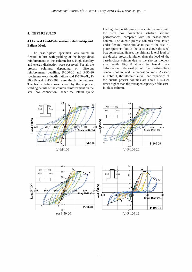
The cast-in-place specimen was failed in
flexural failure with yielding of the longitudinal
reinforcement at the column base. High ductility
and energy dissipation were observed. For all the
precast columns, depending on different
reinforcement detailing, P-100-20 and P-50-20
specimens were ductile failure and P-100-20L, P-
100-16 and P-150-20L were the brittle failures.
The brittle failure was caused by the improper
welding details of the column reinforcement on the
steel box connection. Under the lateral cyclic
loading, the ductile precast concrete columns with
the steel box connection satisfied seismic
performances, compared with the cast-in-place
column. The ductile precast columns were failed
under flexural mode similar to that of the cast-in-
place specimen but at the section above the steel
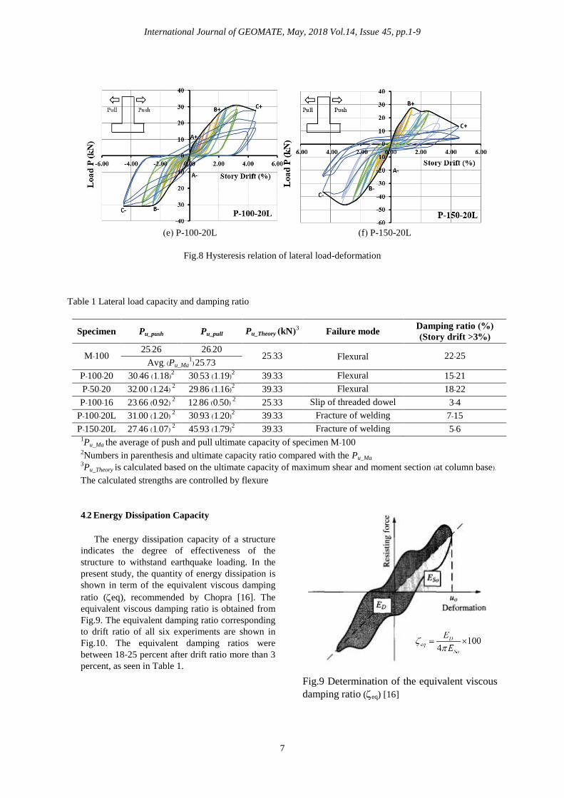
box connection. Hence, the ultimate lateral load of
the ductile precast is higher than the load of the
cast-in-place column due to the shorter moment
arm length. Figs 8 shows the lateral load-
deformation relationship of the cast-in-place
concrete column and the precast columns. As seen
in Table 1, the ultimate lateral load capacities of
the ductile precast columns are about 1.16-1.24
times higher than the averaged capacity of the cast-
in-place column.
(a) M-100 (b) P-100-20
(c) P-50-20 (d) P-100-16
International Journal of GEOMATE, May, 2018 Vol.14, Issue 45, pp.1-9
7
(e) P-100-20L (f) P-150-20L
Fig.8 Hysteresis relation of lateral load-deformation
Table 1 Lateral load capacity and damping ratio
Specimen Pu_push Pu_pull Pu_Theory (kN)3 Failure mode
Damping ratio (%)
(Story drift >3%)
M-100 25.26 26.20
25.33 Flexural 22-25 Avg. (Pu_Ma
1) 25.73
P-100-20 30.46 (1.18)2 30.53 (1.19)2 39.33 Flexural 15-21
P-50-20 32.00 (1.24) 2 29.86 (1.16)2 39.33 Flexural 18-22
P-100-16 23.66 (0.92) 2 12.86 (0.50) 2 25.33 Slip of threaded dowel 3-4
P-100-20L 31.00 (1.20) 2 30.93 (1.20)2 39.33 Fracture of welding 7-15
P-150-20L 27.46 (1.07) 2 45.93 (1.79)2 39.33 Fracture of welding 5-6 1Pu_Ma the average of push and pull ultimate capacity of specimen M-100
2Numbers in parenthesis and ultimate capacity ratio compared with the Pu_Ma
3Pu_Theory is calculated based on the ultimate capacity of maximum shear and moment section (at column base).
The calculated strengths are controlled by flexure
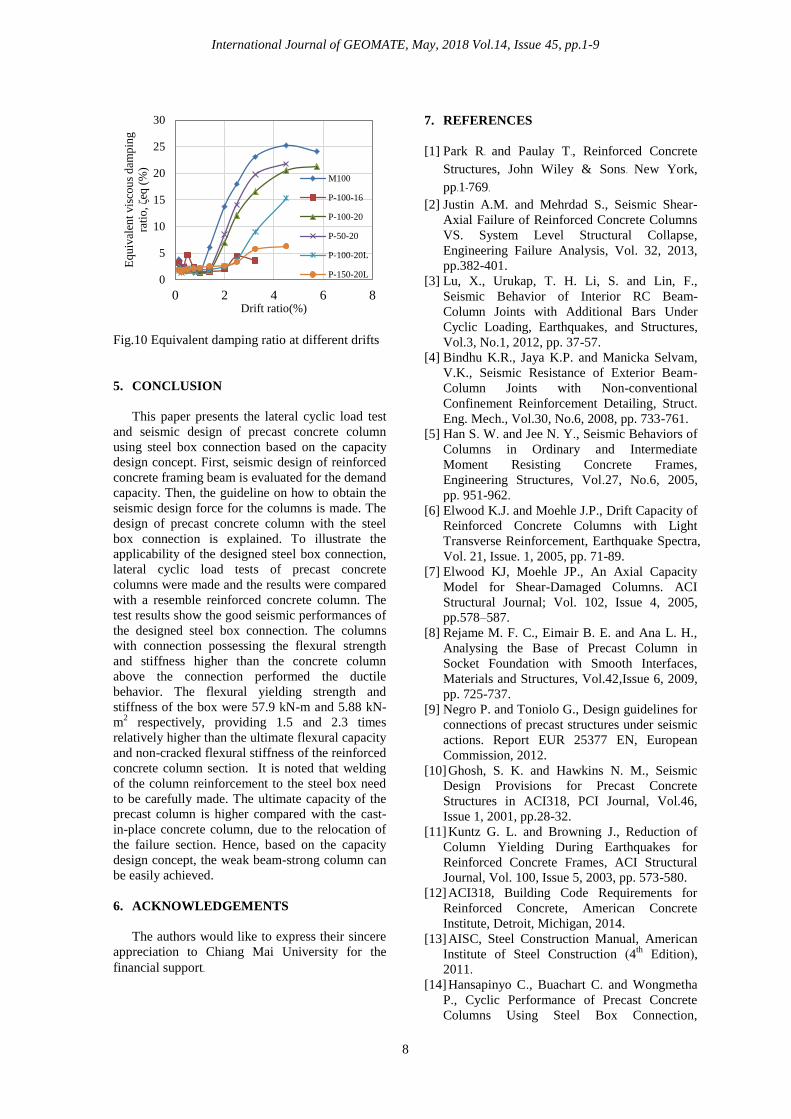
4.2 Energy Dissipation Capacity
The energy dissipation capacity of a structure
indicates the degree of effectiveness of the
structure to withstand earthquake loading. In the
present study, the quantity of energy dissipation is
shown in term of the equivalent viscous damping
ratio (eq), recommended by Chopra [16]. The
equivalent viscous damping ratio is obtained from
Fig.9. The equivalent damping ratio corresponding
to drift ratio of all six experiments are shown in
Fig.10. The equivalent damping ratios were
between 18-25 percent after drift ratio more than 3
percent, as seen in Table 1.
Fig.9 Determination of the equivalent viscous
damping ratio (eq) [16]
International Journal of GEOMATE, May, 2018 Vol.14, Issue 45, pp.1-9
8
Fig.10 Equivalent damping ratio at different drifts
5. CONCLUSION
This paper presents the lateral cyclic load test
and seismic design of precast concrete column
using steel box connection based on the capacity
design concept. First, seismic design of reinforced
concrete framing beam is evaluated for the demand
capacity. Then, the guideline on how to obtain the
seismic design force for the columns is made. The
design of precast concrete column with the steel
box connection is explained. To illustrate the
applicability of the designed steel box connection,
lateral cyclic load tests of precast concrete
columns were made and the results were compared
with a resemble reinforced concrete column. The
test results show the good seismic performances of
the designed steel box connection. The columns
with connection possessing the flexural strength
and stiffness higher than the concrete column
above the connection performed the ductile
behavior. The flexural yielding strength and
stiffness of the box were 57.9 kN-m and 5.88 kN-
m2 respectively, providing 1.5 and 2.3 times
relatively higher than the ultimate flexural capacity
and non-cracked flexural stiffness of the reinforced
concrete column section. It is noted that welding
of the column reinforcement to the steel box need
to be carefully made. The ultimate capacity of the
precast column is higher compared with the cast-
in-place concrete column, due to the relocation of
the failure section. Hence, based on the capacity
design concept, the weak beam-strong column can
be easily achieved.
6. ACKNOWLEDGEMENTS
The authors would like to express their sincere
appreciation to Chiang Mai University for the
financial support.
7. REFERENCES
[1] Park R. and Paulay T., Reinforced Concrete
Structures, John Wiley & Sons. New York,
pp.1-769. [2] Justin A.M. and Mehrdad S., Seismic Shear-
Axial Failure of Reinforced Concrete Columns
VS. System Level Structural Collapse,
Engineering Failure Analysis, Vol. 32, 2013,
pp.382-401.
[3] Lu, X., Urukap, T. H. Li, S. and Lin, F.,
Seismic Behavior of Interior RC Beam-
Column Joints with Additional Bars Under
Cyclic Loading, Earthquakes, and Structures,
Vol.3, No.1, 2012, pp. 37-57.
[4] Bindhu K.R., Jaya K.P. and Manicka Selvam,
V.K., Seismic Resistance of Exterior Beam-
Column Joints with Non-conventional
Confinement Reinforcement Detailing, Struct.
Eng. Mech., Vol.30, No.6, 2008, pp. 733-761.
[5] Han S. W. and Jee N. Y., Seismic Behaviors of
Columns in Ordinary and Intermediate
Moment Resisting Concrete Frames,
Engineering Structures, Vol.27, No.6, 2005,
pp. 951-962.
[6] Elwood K.J. and Moehle J.P., Drift Capacity of
Reinforced Concrete Columns with Light
Transverse Reinforcement, Earthquake Spectra,
Vol. 21, Issue. 1, 2005, pp. 71-89.
[7] Elwood KJ, Moehle JP., An Axial Capacity
Model for Shear-Damaged Columns. ACI
Structural Journal; Vol. 102, Issue 4, 2005,
pp.578–587.
[8] Rejame M. F. C., Eimair B. E. and Ana L. H.,
Analysing the Base of Precast Column in
Socket Foundation with Smooth Interfaces,
Materials and Structures, Vol.42,Issue 6, 2009,
pp. 725-737.
[9] Negro P. and Toniolo G., Design guidelines for
connections of precast structures under seismic
actions. Report EUR 25377 EN, European
Commission, 2012.
[10] Ghosh, S. K. and Hawkins N. M., Seismic
Design Provisions for Precast Concrete
Structures in ACI318, PCI Journal, Vol.46,
Issue 1, 2001, pp.28-32.
[11] Kuntz G. L. and Browning J., Reduction of
Column Yielding During Earthquakes for
Reinforced Concrete Frames, ACI Structural
Journal, Vol. 100, Issue 5, 2003, pp. 573-580.
[12] ACI318, Building Code Requirements for
Reinforced Concrete, American Concrete
Institute, Detroit, Michigan, 2014.
[13] AISC, Steel Construction Manual, American
Institute of Steel Construction (4th
Edition),
2011.
[14] Hansapinyo C., Buachart C. and Wongmetha
P., Cyclic Performance of Precast Concrete
Columns Using Steel Box Connection,
0
5
10
15
20
25
30
0 2 4 6 8
Eq
uiv
alen
t vis
cou
s d
amp
ing
rati
o, ζe
q (
%)
Drift ratio(%)
M100
P-100-16
P-100-20
P-50-20
P-100-20L
P-150-20L
International Journal of GEOMATE, May, 2018 Vol.14, Issue 45, pp.1-9
9
International Journal of Civil Engineering, Vol.
15, Issue 4, 2017, pp. 663–676.
[15] ACI T1.1-01, Acceptance Criteria for Moment
Frames Based on Structural Testing, American
Concrete Institute, 2001.
[16] Chopra, A. K., Theory and Applications to
Earthquake Engineering: Dynamic of structure
(3rd
Edition), Prentice Hall, Englewood Cliffs,
NJ, 1999.
Copyright © Int. J. of GEOMATE. All rights reserved,
including the making of copies unless permission is
obtained from the copyright proprietors.