Embed Size (px)
Citation preview
Capacitance standard using an electron pump
Paul LeeWayne FungGeorge IoannouSmitesh Bakrania
Based on work published by Keller, Martinis, Zimmerman and Steinbach (1996 to 1999)
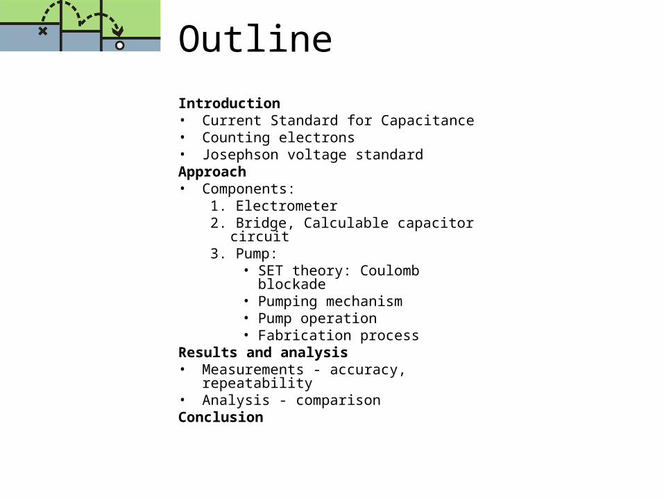
Outline
Introduction• Current Standard for Capacitance • Counting electrons• Josephson voltage standard Approach• Components:
1. Electrometer2. Bridge, Calculable capacitor circuit3. Pump:
• SET theory: Coulomb blockade• Pumping mechanism • Pump operation• Fabrication process
Results and analysis• Measurements - accuracy, repeatability• Analysis - comparisonConclusion

Introduction
Paul LeeWayne Fung
Current Standard for Capacitance Counting electronsJosephson voltage standard
Current Standard for Capacitance
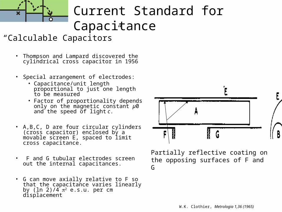
“Calculable Capacitors”
• Thompson and Lampard discovered the cylindrical cross capacitor in 1956
• Special arrangement of electrodes:• Capacitance/unit length proportional
to just one length to be measured• Factor of proportionality depends only
on the magnetic constant µ0 and the speed of light c.
• A,B,C, D are four circular cylinders (cross capacitor) enclosed by a movable screen E, spaced to limit cross capacitance.
• F and G tubular electrodes screen out the internal capacitances.
• G can move axially relative to F so that the capacitance varies linearly by (ln 2)/42 e.s.u. per cm displacement
W.K. Clothier, Metrologia 1,36 (1965)
Partially reflective coating on the opposing surfaces of F and G
Why Consider an Alternative?
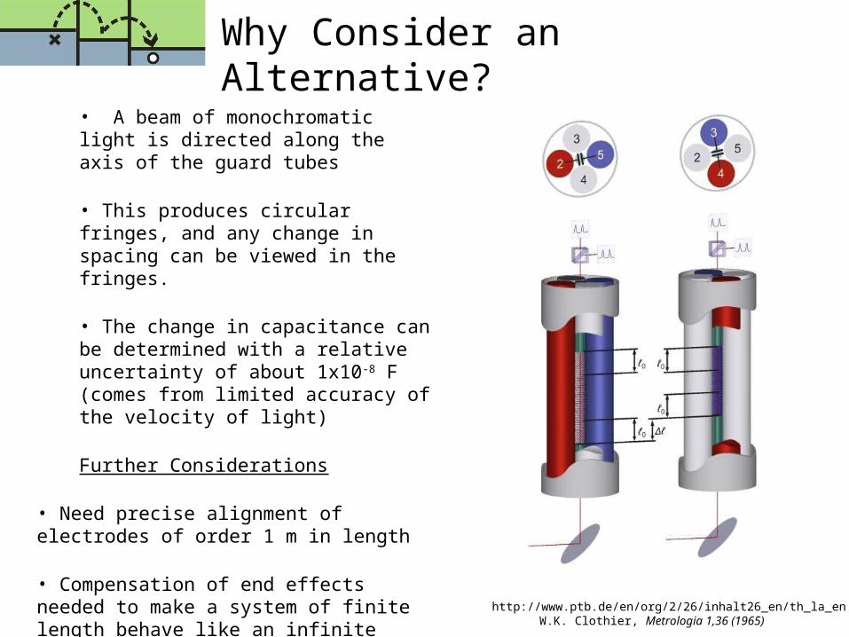
• A beam of monochromatic light is directed along the axis of the guard tubes
• This produces circular fringes, and any change in spacing can be viewed in the fringes.
• The change in capacitance can be determined with a relative uncertainty of about 1x10⁻⁸ F (comes from limited accuracy of the velocity of light)
Further Considerations
• Need precise alignment of electrodes of order 1 m in length
• Compensation of end effects needed to make a system of finite length behave like an infinite system over a limited range
W.K. Clothier, Metrologia 1,36 (1965)http://www.ptb.de/en/org/2/26/inhalt26_en/th_la_en.htm
Let’s Go Smaller!
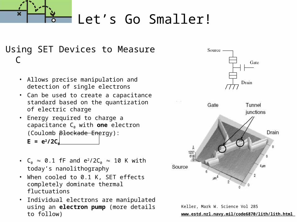
Using SET Devices to Measure C
• Allows precise manipulation and detection of single electrons
• Can be used to create a capacitance standard based on the quantization of electric charge
• Energy required to charge a capacitance C0 with one electron (Coulomb Blockade Energy):
E = e2/2C0
• C0 0.1 fF and e2/2C0 10 K with today’s nanolithography
• When cooled to 0.1 K, SET effects completely dominate thermal fluctuations
• Individual electrons are manipulated using an electron pump (more details to follow) Keller, Mark W. Science Vol 285
www.estd.nrl.navy.mil/code6870/lith/lith.html

Main Idea Behind Electron Counting
Keller, Mark W. Science Vol 285
Capacitance Defined Based on Counting Electrons
• Very Simple Concept!• The charge transfer of a single
electron of charge Q from one conductor to the next creates a potential difference V
• C = Q / V = Ne / V
• Larger sample size gives better accuracy
• Proposed standard requires pumping ~108 electrons onto a 1 pF capacitor with uncertainty in the number of electrons of 1
Uncertainties in new standard
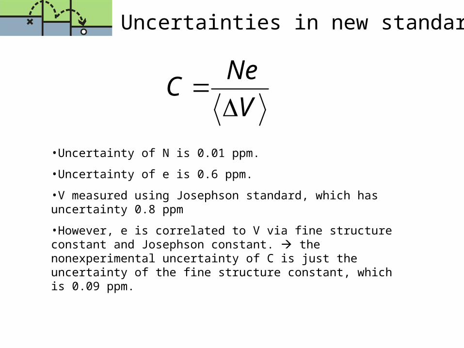
•Uncertainty of N is 0.01 ppm.
•Uncertainty of e is 0.6 ppm.
•V measured using Josephson standard, which has uncertainty 0.8 ppm
•However, e is correlated to V via fine structure constant and Josephson constant. the nonexperimental uncertainty of C is just the uncertainty of the fine structure constant, which is 0.09 ppm.
V
NeC

Quantum Metrology Triangle
• According to theory, 3 relations, 2 unknowns e and h test the triangle.
•Measure the voltage across a Josephson junction driven at frequency f V = f / KJ
• Measure the current of an SET pump, pumping at frequency f I = Q f
•Measure the quantum Hall resistance RH
•Compare whether V / I = RH
•If experiments do not agree with the triangle to at least 0.01 ppm, then one of the relations is not valid new physics needed
Approach
George IoannouWayne FungSmitesh Bakrania
1. Electrometer
2. Bridge Circuit and Ref. Capacitor
3. Electron Pump
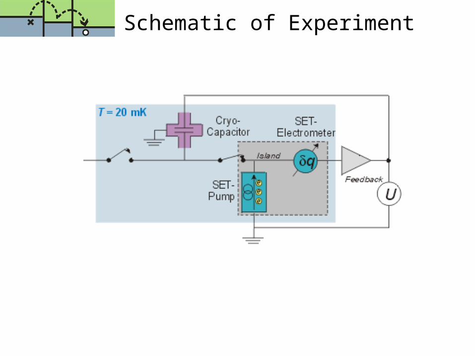
Schematic of Experiment

Electrometer
Used to measure Vp across the external island
Necessary because of very sensitive measurements
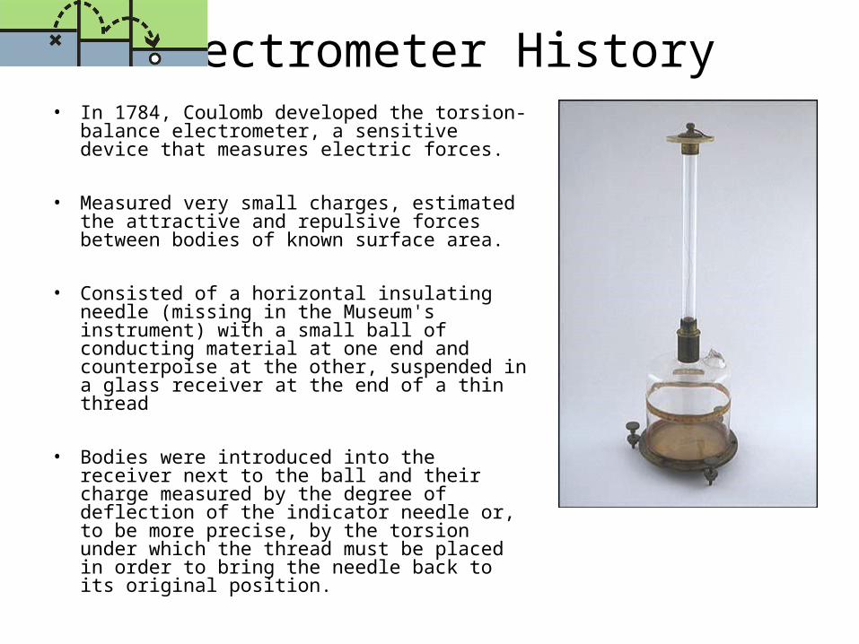
Electrometer History• In 1784, Coulomb developed the torsion-
balance electrometer, a sensitive device that measures electric forces.
• Measured very small charges, estimated the attractive and repulsive forces between bodies of known surface area.
• Consisted of a horizontal insulating needle (missing in the Museum's instrument) with a small ball of conducting material at one end and counterpoise at the other, suspended in a glass receiver at the end of a thin thread
• Bodies were introduced into the receiver next to the ball and their charge measured by the degree of deflection of the indicator needle or, to be more precise, by the torsion under which the thread must be placed in order to bring the needle back to its original position.
Modern Electrometers
• Researchers have scaled Coulomb’s invention down to just a few micrometers in size.
• Andrew L. Cleland of the University of California, Santa Barbara and Michael L. Roukes of the California Institute of Technology in Pasadena fashioned the miniature electrometer out of silicon
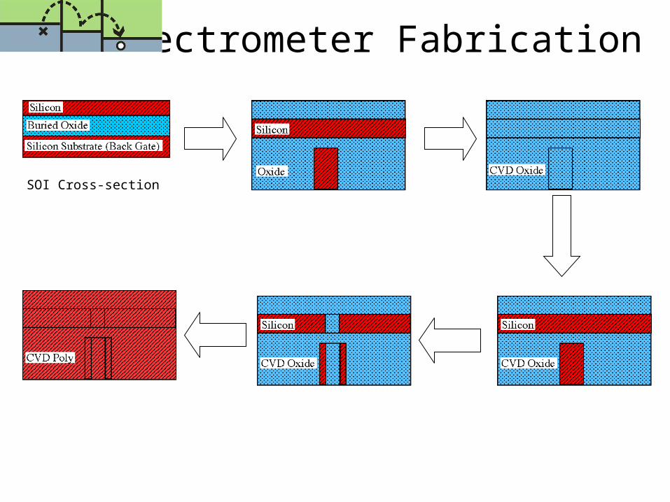
Electrometer Fabrication
SOI Cross-section

Top View Cross Section
Electrometer Fabrication
Electrometer Usage
• Movable electrode rests on a paddle attached to a thin, flexible beam that twists and vibrates in response to electric attraction
• Motion can be detected by applying a magnetic field
• Vibrating beam cuts through the magnetic field, generating a voltage that is sensed by another electrode in the device
Electrometer Specs
Operates under high input resistance / lower input incurrent modes
Current sensitivity in the range of 10-15 A
Voltage measurements can be made from 10 MV to 200 mV
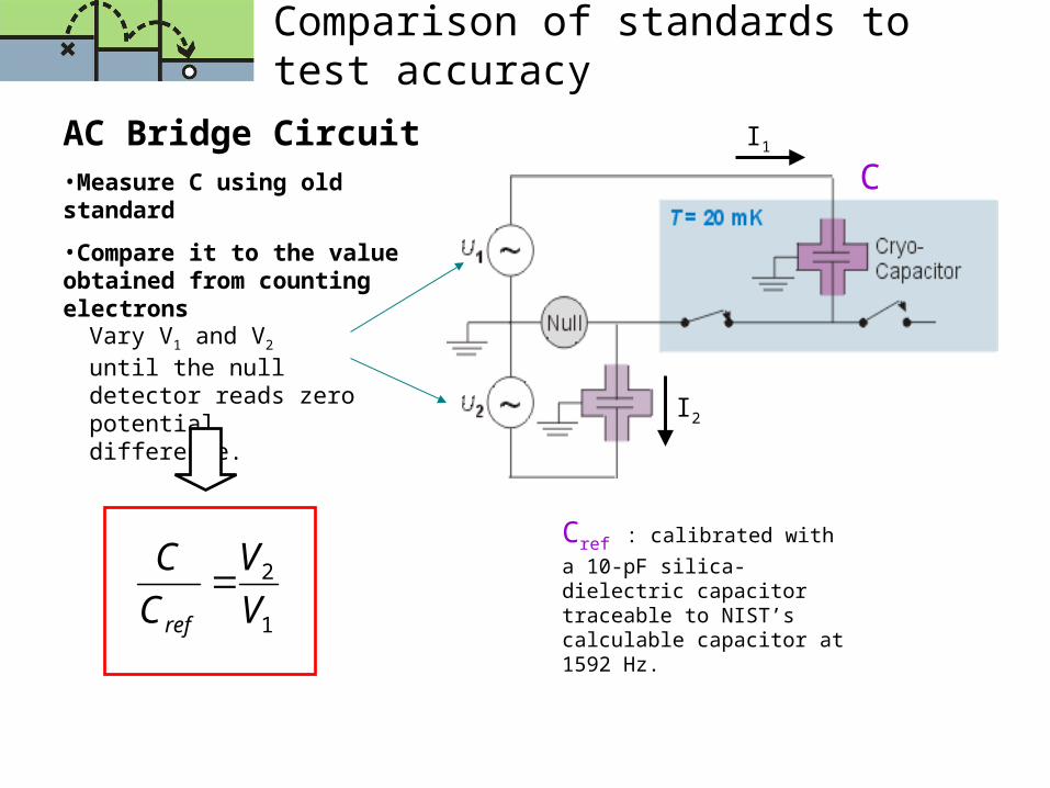
Comparison of standards to test accuracy
Vary V1 and V2 until the null detector reads zero potential difference.
Cref : calibrated with a 10-pF
silica-dielectric capacitor traceable to NIST’s calculable capacitor at 1592 Hz.
I1
I2
AC Bridge Circuit•Measure C using old standard
•Compare it to the value obtained from counting electrons
1
2
V
V
C
C
ref
C
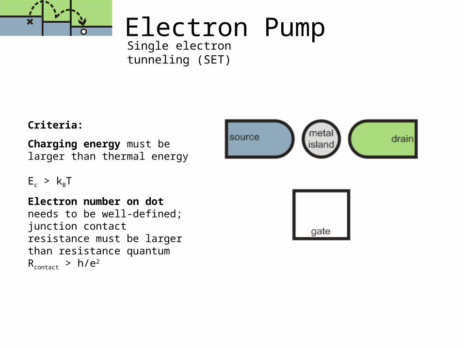
Electron PumpSingle electron tunneling (SET)
Criteria:
Charging energy must be larger than thermal energy Ec > kBT
Electron number on dot needs to be well-defined; junction contact resistance must be larger than resistance quantumRcontact > h/e2

Electron PumpSingle electron tunneling (SET) Theory
Electrostatic energy for island with N electrons:
Q2/2C = (Ne)2/2C
__________________________
Total energy on island:
U(N) = Ei + (Ne)2/2C
__________________________
Electrochemical potential:
N+1 = (N+0.5)e2/C + e/C [CiVi]
__________________________
Charging energy:
= N+1 - N=Ec=e2/C
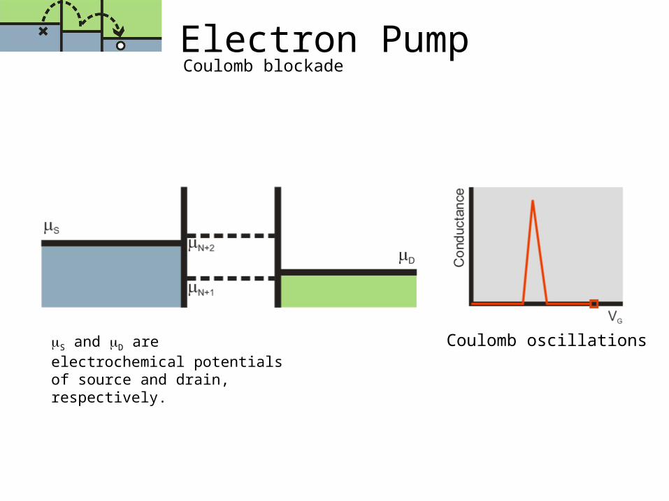
Electron PumpCoulomb blockade
Coulomb oscillationsS and D are electrochemical potentials of source and drain, respectively.
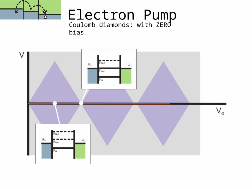
Electron PumpCoulomb diamonds: with ZERO bias

Coulomb diamonds: with NON-ZERO biasElectron Pump
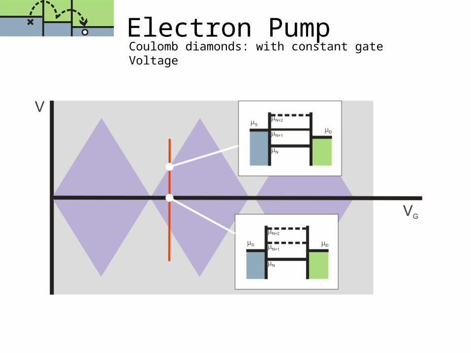
Electron PumpCoulomb diamonds: with constant gate Voltage

Electron PumpThe idea behind single electron pump: a counter
Electron counting accuracy is critical
Even with a coulomb blockade an electron may virtually tunnel into the island
This is avoided by having multiple junctions (multiple blockades)
Chain of metal islands separated by tunnel junctions, with gate electrodes coupled capacitively to each island
Trapping electrons
Electron PumpGoals
Proposed standard requires pumping of ~108 electrons onto a 1 pF capacitor with an uncertainty in the number of electrons of ± 1
Small leakage rate when the gate pulses are turned off (the hold mode) so that the charge on the capacitor remains fixed while the voltage is measured
To maximize the coulomb blockade and thus minimize unwanted tunneling events, the total capacitance of each island in the pump must be small
Charging needs to be large, total capacitance must be small (Ec = e2/Ctotal)
Electron Pump“side effects”
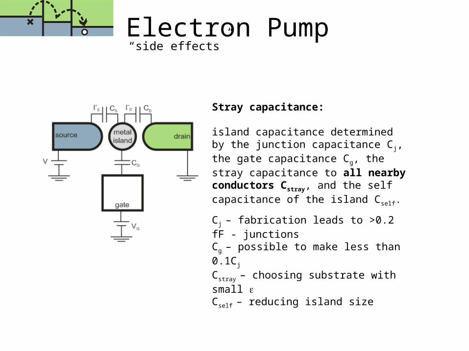
Stray capacitance:
island capacitance determined by the junction capacitance Cj, the gate capacitance Cg, the stray capacitance to all nearby conductors Cstray, and the self capacitance of the island Cself.
Cj – fabrication leads to >0.2 fF - junctions
Cg – possible to make less than 0.1Cj
Cstray – choosing substrate with small Cself – reducing island size
Electron PumpMultiple junction electron pump
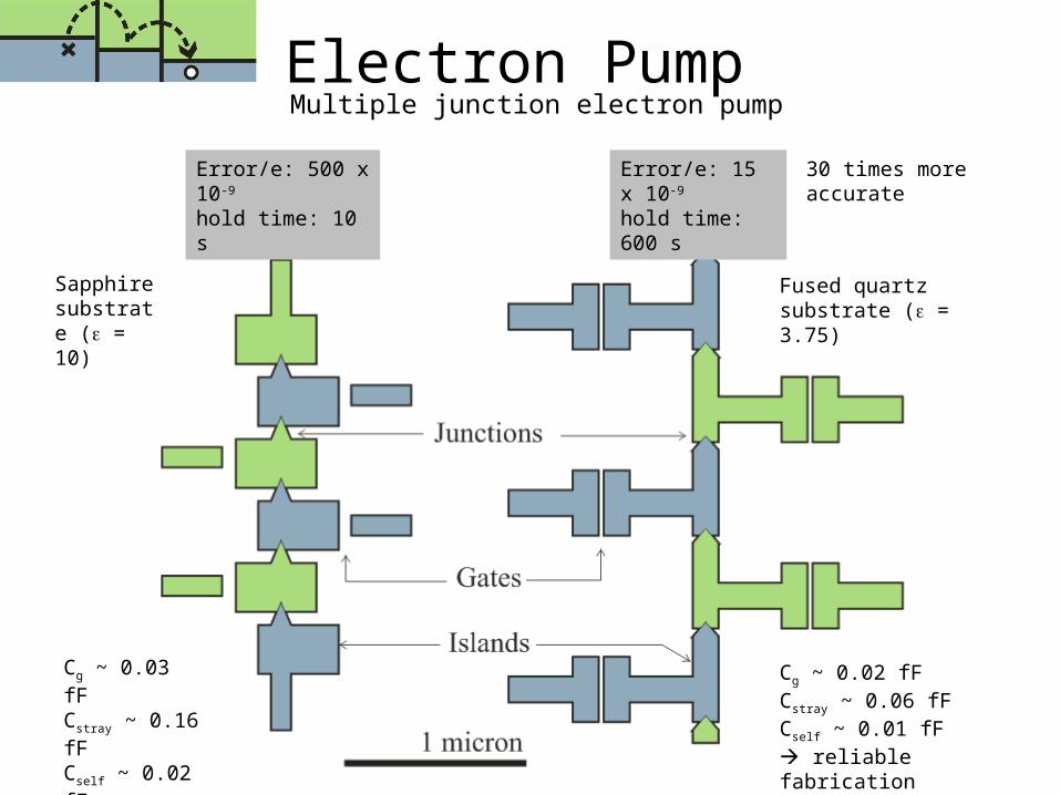
30 times more accurate
Error/e: 500 x 10-9
hold time: 10 sError/e: 15 x 10-9
hold time: 600 s
Sapphire substrate ( = 10)
Fused quartz substrate ( = 3.75)
Cg ~ 0.03 fFCstray ~ 0.16 fFCself ~ 0.02 fF
Cg ~ 0.02 fFCstray ~ 0.06 fFCself ~ 0.01 fF reliable fabrication
Electron Pump“side effects”
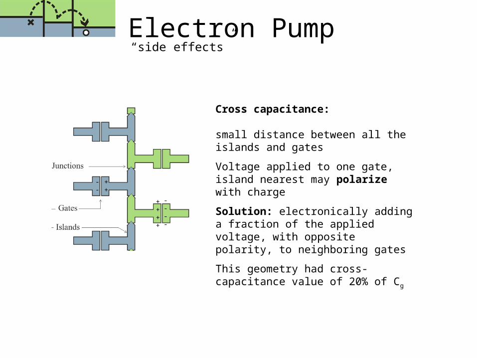
Cross capacitance:
small distance between all the islands and gates
Voltage applied to one gate, island nearest may polarize with charge
Solution: electronically adding a fraction of the applied voltage, with opposite polarity, to neighboring gates
This geometry had cross-capacitance value of 20% of Cg
++++
----
--
++

Electron PumpMultiple junction electron pump
Electron pump and electrometer
Cryogenic capacitor
Switches
Magnetically controlled switches
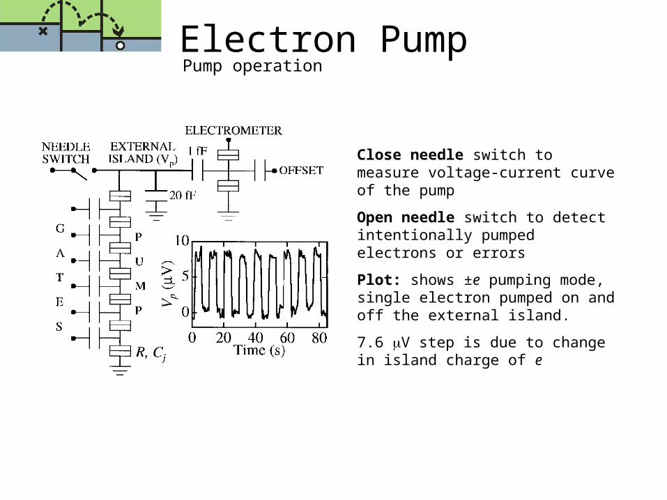
Electron PumpPump operation
Close needle switch to measure voltage-current curve of the pump
Open needle switch to detect intentionally pumped electrons or errors
Plot: shows ±e pumping mode, single electron pumped on and off the external island.
7.6 V step is due to change in island charge of e
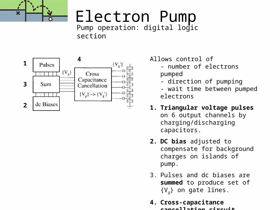
Electron PumpPump operation: digital logic section
Allows control of - number of electrons pumped- direction of pumping- wait time between pumped electrons
1. Triangular voltage pulses on 6 output channels by charging/discharging capacitors.
2. DC bias adjusted to compensate for background charges on islands of pump.
3. Pulses and dc biases are summed to produce set of {Vg} on gate lines.
4. Cross-capacitance cancellation circuit performs transformation producing set of {Vg’}
1
2
3
4
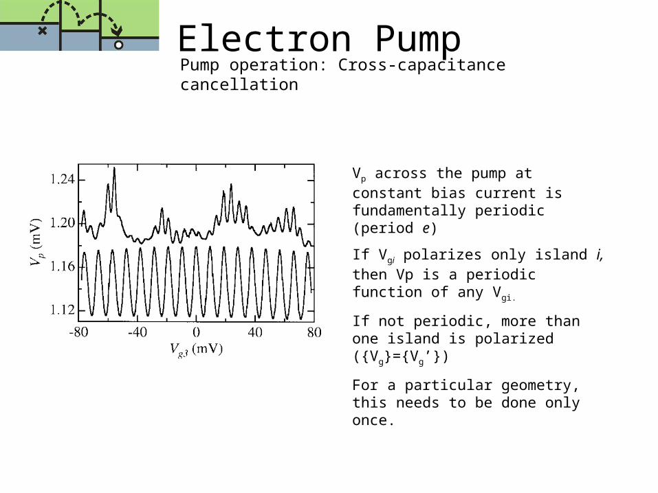
Electron PumpPump operation: Cross-capacitance cancellation
Vp across the pump at constant bias current is fundamentally periodic (period e)
If Vgi polarizes only island i, then Vp is a periodic function of any Vgi.
If not periodic, more than one island is polarized ({Vg}={Vg’})
For a particular geometry, this needs to be done only once.
Electron PumpPump operation: error detection
Background charges in the junction oxide or substrate produce random island polarization of order e over time.
DC biases tuned so each island charge in the absence of gate pulse is much smaller than e.
In ±e mode, operate faster than electrometer – hence constant electrometer signal as long as no errors are present.
An error causes sudden jump in the signal.
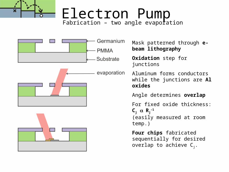
Fabrication – two angle evaporationElectron Pump
Mask patterned through e-beam lithography
Oxidation step for junctions
Aluminum forms conductors while the junctions are Al oxides
Angle determines overlap
For fixed oxide thickness: Cj Rj-1
(easily measured at room temp.)
Four chips fabricated sequentially for desired overlap to achieve Cj.
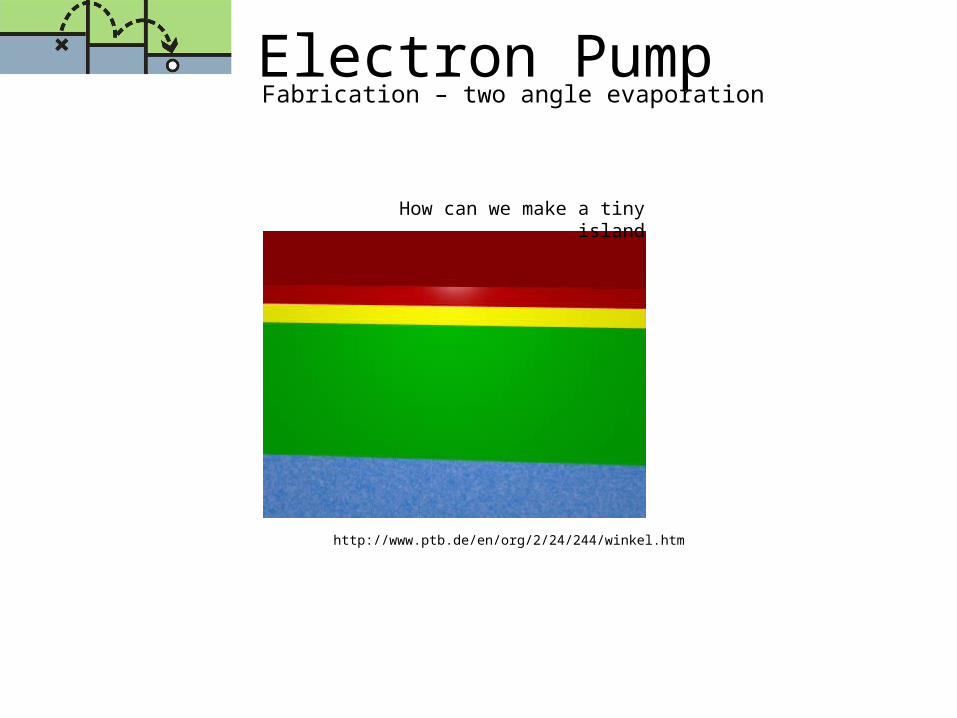
Fabrication – two angle evaporationElectron Pump
http://www.ptb.de/en/org/2/24/244/winkel.htm
How can we make a tiny island

Electron Pump7-junction electron pump
1m
Tunnel junctions
Gate Capacitor
Dual image due to two-angle evaporation
http://www.jcnabity.com/nistpump.htm
Results and Analysis
George Ioannou
Paul Lee
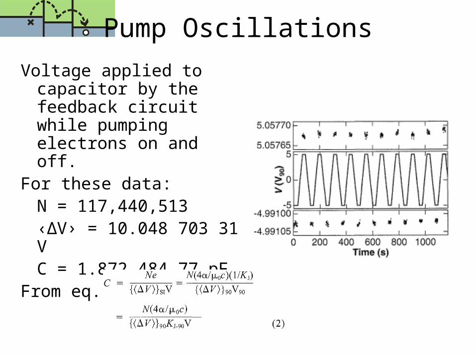
Voltage applied to capacitor by the feedback circuit while pumping electrons on and off.
For these data:N = 117,440,513 ‹∆V› = 10.048 703 31 VC = 1.872 484 77 pF
From eq.
Pump Oscillations
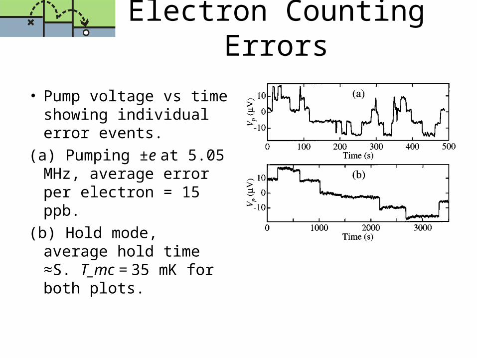
• Pump voltage vs time showing individual error events.
(a) Pumping ±e at 5.05 MHz, average error per electron = 15 ppb.
(b) Hold mode, average hold time ≈S. T_mc = 35 mK for both plots.
Electron Counting Errors
Pump accuracy vs. Time
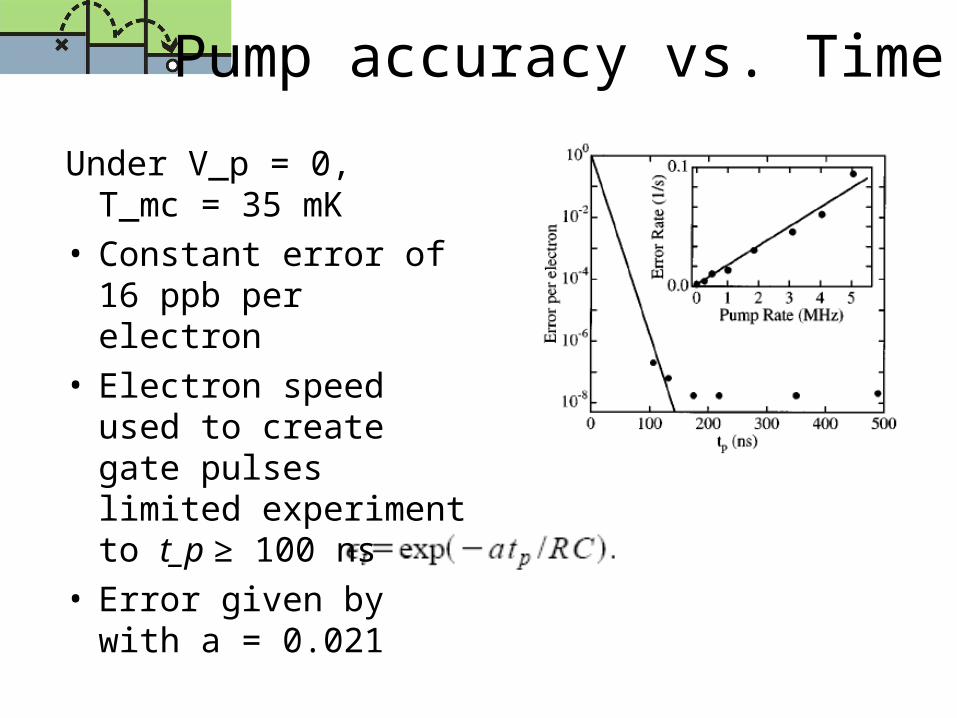
Under V_p = 0, T_mc = 35 mK
• Constant error of 16 ppb per electron
• Electron speed used to create gate pulses limited experiment to t_p ≥ 100 ns
• Error given bywith a = 0.021
Temperature Effect on Pump Accuracy and Leakage Rate
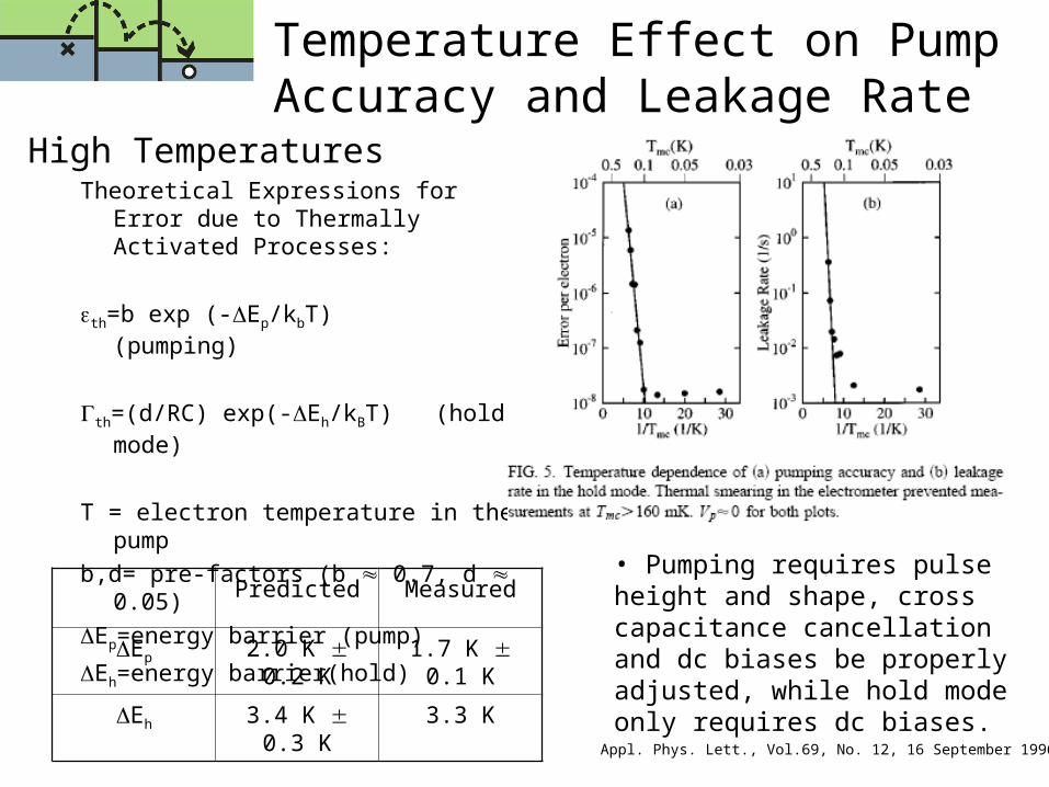
High TemperaturesTheoretical Expressions for Error due to
Thermally Activated Processes:
th=b exp (-Ep/kbT) (pumping)
th=(d/RC) exp(-Eh/kBT) (hold mode)
T = electron temperature in the pump
b,d= pre-factors (b 0.7, d 0.05)
Ep=energy barrier (pump)
Eh=energy barrier(hold)
Appl. Phys. Lett., Vol.69, No. 12, 16 September 1996
Predicted Measured
Ep 2.0 K 0.2 K 1.7 K 0.1 K
Eh 3.4 K 0.3 K 3.3 K
• Pumping requires pulse height and shape, cross capacitance cancellation and dc biases be properly adjusted, while hold mode only requires dc biases.

Low Temperatures
• At low temperatures, error and leakage are both independent of temperature Tmc (T is not equal to Tmc for Tmc < 100 mK)
• At low temperatures, the power dissipation due to the electrometer and to the electrons passing through the pump are so small that any tiny deviances in temperature are negligible.
• At low T, the error mechanism comes from photon-assisted cotunneling.
• An environment containing a time-varying voltage source with spectral components at frequencies corresponding to the charging energy (typically 10 GHz) will significantly increase tunneling rates, because it will generate photons of sufficient energy to overcome the charging energy barrier.
Appl. Phys. Lett., Vol.69, No. 12, 16 September 1996
http://www.fys.ku.dk/flensberg/publications/prb_accotun.pdf
Temperature Effect on Pump Accuracy and Leakage Rate (2)
Repeatability of SET Capacitance Standard
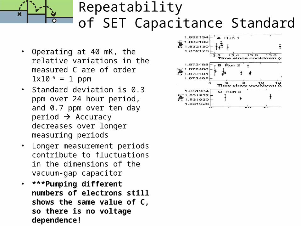
• Operating at 40 mK, the relative variations in the measured C are of order 1x10-6 = 1 ppm
• Standard deviation is 0.3 ppm over 24 hour period, and 0.7 ppm over ten day period Accuracy decreases over longer measuring periods
• Longer measurement periods contribute to fluctuations in the dimensions of the vacuum-gap capacitor
• ***Pumping different numbers of electrons still shows the same value of C, so there is no voltage dependence!
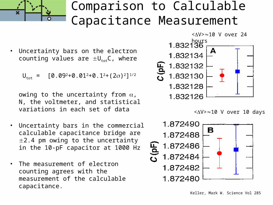
Comparison to Calculable Capacitance Measurement
• Uncertainty bars on the electron counting values are UtotC, where
Utot = [0.092+0.012+0.12+(2)2]1/2
owing to the uncertainty from , N, the voltmeter, and statistical variations in each set of data
• Uncertainty bars in the commercial calculable capacitance bridge are 2.4 pm owing to the uncertainty in the 10-pF capacitor at 1000 Hz
• The measurement of electron counting agrees with the measurement of the calculable capacitance. Keller, Mark W. Science Vol 285
<V>10 V over 24 hours
<V>10 V over 10 days
3R’s for Future Improvements
To Realize the SET Capacitance Standard:
• 1) Reduce the frequency dependence of the cryogenic capacitor because the measurement of C by counting electrons occurs at much lower effective frequency than that used for bridge comparisons
• 2) Reduce the input noise of the electrometer to allow the feedback circuit to maintain virtual ground between the pump and capacitor
• 3) Reduce the magnitude of all uncertainties in both pump and hold modes in the circuit
Keller, Mark W. Science Vol 285
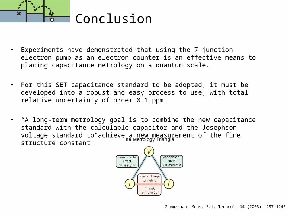
Conclusion
• Experiments have demonstrated that using the 7-junction electron pump as an electron counter is an effective means to placing capacitance metrology on a quantum scale.
• For this SET capacitance standard to be adopted, it must be developed into a robust and easy process to use, with total relative uncertainty of order 0.1 ppm.
• “A long-term metrology goal is to combine the new capacitance standard with the calculable capacitor and the Josephson voltage standard to achieve a new measurement of the fine structure constant”
Zimmerman, Meas. Sci. Technol. 14 (2003) 1237–1242
ReferencesM. W. Keller, J. M. Martinis, A. H. Steinbach and N. M. Zimmerman, Accuracy of electron counting using a 7-junction electron pump, APL, 69 (1996) 1804-1806
M. W. Keller, J. M. Martinis, A. H. Steinbach and N. M. Zimmerman, A Seven-Junction Electron Pump: Design, Fabrication and Operation, IEEE Trans. Inst. Meas., 46 (1997) 307-310
M. W. Keller, A. L. Eichenberger, J. M. Martinis and N. M. Zimmerman, A Capacitance Standard Based on Counting Electrons, Science, 285 (1999), 1706-1709
N M Zimmerman and M W Keller, Electrical metrology with single electrons, Meas. Sci. Technol. 14 (2003) 1237–1242
Thank you
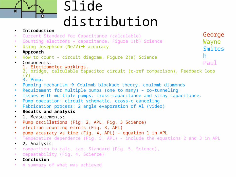
Slide distribution• Introduction• Current Standard for Capacitance (calculable)• Counting electrons – capacitance, Figure 1(b) Science• Using Josephson (Ne/V) accuracy• Approach• How to count – circuit diagram, Figure 2(a) Science• Components:
1. Electrometer workings, 2. bridge, calculable capacitor circuit (c-ref comparison), Feedback loop (?)3. Pump:
• Pumping mechanism Coulomb blockade theory, coulomb diamonds• Requirement for multiple pumps (one to many) – co-tunneling• Issues with multiple pumps: cross-capacitance and stray capacitance.• Pump operation: circuit schematic, cross-c canceling• Fabrication process: 2 angle evaporation of Al (video)• Results and analysis• 1. Measurements: • Pump oscillations (Fig. 2, APL, Fig. 3 Science) • electron counting errors (Fig. 3, APL)• pump accuracy vs time (Fig. 4, APL) – equation 1 in APL• Temperature dependence (Fig. 5, APL) – include the equations 2 and 3 in APL• 2. Analysis: • comparison to calc. cap. Standard (Fig. 5, Science), • repeatability (Fig. 4, Science) • Conclusion• A summary of what was achieved
GeorgeWayneSmiteshPaul

Fine-structure constant• A dimensionless number ()
• Ratio of energy required to bring two electrons from infinity to some distance S and the photon energy of wavelength 2S
• It was first used to explain the size of splitting of the hydrogen lines
• “For instance, were α to change by 4%, carbon would no longer be produced in stellar fusion. If α were greater than 0.1, fusion would no longer occur in stars.”
ch
e2