Embed Size (px)
Citation preview

9
CAPABILITIES ANDMODELING
LIMITATIONS OF LYNX GEOSCIENCESYSTEM (GMS) SOFTWARE
Prepared for
Nuclear Regulatory CommissionContract NRC-02-88-005
Prepared by
Gerry L. Stirewalt
Center for Nuclear Waste Regulatory AnalysesSan Antonio, Texas
September 1993

CONTENTS
Section Page
TABLES ...................... iiiACKNOWLEDGMENTS ................. iv
I PURPOSE OF REPORT ........................................ 1-1
2 GENERAL FEATURES OF LYNX GMS SOFTWARE .2-1
3 CAPABILITIES OF GMS SOFTWARE .3-13.1 BENEFITS OF GMS AS A TOOL FOR REGULATORY REVIEW AND ANALYSIS . 3-13.2 SYSTEM AND APPLICATIONS MODULES OF GMS SOFTWARE .3-13.3 OPTIONAL APPLICATION MODULES FOR GMS .3-3
4 PERCEIVED LIMITATIONS OF GMS SOFTWARE .4-1
5 HARDWARE REQUIREMENTS AND ADAPTABILITY TO NRC HARDWARE 5-15.1 HARDWARE CONFIGURATION REQUIREMENTS ...................... 5-15.2 ADAPTABILITY TO NRC HARDWARE .5-1
6 COST OF SOFTWARE AND ASSOCIATED ITEMS .6-16.1 SOFTWARE LICENSE AND RENTAL FEES .6-16.2 MAINTENANCE AND SUPPORT .6-16.3 INSTALLATION AND TRAINING ................................. 6-26.4 EXAMPLES FOR PRICING MULTIPLE-USER/NETWORKED AND
SINGLE-USER CONFIGURATIONS .6-2
7 USE OF LYNX GMS SOFTWARE BY THE USGS IN THE YUCCAMOUNTAIN PROJECT ................................ 7-1
8 SUMMARY .......................... 8-1
9 REFERENCES .............................................. 9-1
APPENDIX A - PRODUCT INFORMATION SHEETS FROM LYNX GEOSYSTEMS, INC. . A-I
APPENDIX B - ATTENDEES AT THE NRC/DOE APPENDIX 7 MEETING .... ...... B-1
ii

* 0TABLES
Number Page
6-1 Hypothetical Multiple-User/Networked Configuration ....................... 6-36-2 Hypothetical Single-User Configuration .......... ..................... 64
iii

ACKNOWLEDGMENTS
This report was prepared to document work performed by the Center for Nuclear Waste RegulatoryAnalyses (CNWRA) for the U.S. Nuclear Regulatory Commission (NRC) under Contract No. NRC-02-88-005. The activities reported here were performed on behalf of the NRC Office of Nuclear MaterialSafety and Safeguards, Division of High-Level Waste Management. The report is an independent productof the CNWRA and does not necessarily reflect the views or regulatory position of the NRC.
The author is appreciative of the capable assistance provided by Barbara Long in preparation of the finalreport. Thilda Outhuok and Esther Cantu also contributed to producing the final product in a timelymanner.
iv

1 PURPOSE OF REPORT
Staff of the U.S. Nuclear Regulatory Commission (NRC) will be expected to evaluate geologic data andmodels provided by the U.S. Department of Energy (DOE) during the licensing review process for thefirst high-level radioactive waste (HLW) repository, the potential site for which is located at YuccaMountain, Nevada. Because of this expectation, the NRC requested that the Center for Nuclear WasteRegulatory Analyses (CNWRA) review the software currently being used by the U.S. Geological Survey(USGS) for DOE's Yucca Mountain Project Office (YMPO) in development of a three-dimensionalgeological framework model for Yucca Mountain. The specific software being used by the USGS forthis purpose is the Lynx Geoscience Modeling System (GMS) designed and marketed by LynxGeosystems, Inc., Vancouver, British Columbia, Canada.
The directive for this review was established by a memorandum, dated February 18, 1993, from K.McConnell (NRC) to L. McKague (CNWRA). The purpose of the review was to evaluate Lynx GMSsoftware in relation to several factors - capability to integrate surface and subsurface borehole andgeological data into a three-dimensional solid geometric model, limitations, and adaptability to NRCneeds. The directive required review results to be presented as an administrative item related to majormilestone 20-5702-003-330-034. This report (AD 20-5702-003-340-001) is not a tutorial on how to useLynx GMS, but an assessment of the capabilities, limitations, and adaptability of the software.
Information contained in this report was developed, in part, from knowledge gained during an NRC/DOEAppendix 7 exchange on three-dimensional geological modeling software currently in use by DOE andits contractors. Therefore, the report also serves to summarize the important points discussed at thisexchange. The exchange was held in Denver and Las Vegas on August 10-1 1, 1993, and addressedDOE's use of Lynx GMS software as well as Dynamic Graphics (DGI) Earthvision software. Informationwas also obtained from demonstrations of Lynx GMS software presented by staff from Lynx Geosystems.Inc. at CNWRA in San Antonio, Texas (June 15, 1993) and at NRC in Rockville, Maryland (August19, 1993).
1-1

2 GENERAL FEATURES OF LYNX GMS SOFTWARE
GMS is the interactive, menu-driven computer software system designed by Lynx Geosystems, Inc. formanagement, analysis, modeling, interpretation, and visualization of geological data. Capabilities of thesoftware system include management, review, and analysis of spatial data; geological and geostatisticalmodeling and interpretation in two and three dimensions; volumetrics analysis; and three-dimensionalvisualization. The software system incorporates vector techniques to model hard geologic boundaries andraster techniques to model distribution of variables having a spatial variation. It uses two-dimensionalvisualization for interactive graphics operations involving significant input data (e.g., geologicalinterpretation is first done with two-dimensional cross sections, the medium in which geologistscommonly work for analyzing subsurface geology and structure). Results can be produced as cross-sections, fence diagrams, and fully three-dimensional solid models.
GMS provides a range of import/export options for interfacing with external systems. The principalvehicles for import/export of data are GMS ASCII file formats for borehole and map data. Flexibilityof these formats in GMS accommodates a wide variety of geological data. For example, it is possibleto import seismic information as borehole trace data, profiles, and contours. Lynx GMS uses free-format, self-defining ASCII files for data import, allowing source data to be taken from GeographicInformation System (GIS) storage in ARC/INFO and GENAMAP, Structured Query Language (SQL)database systems such as ORACLE and INGRES, spreadsheet systems, and Computer-Aided Design(CAD) sources. Information can be exported into these systems after processing by GMS. In additionto GMS ASCII files, export facilities include Data Exchange Format (DXF) files (for storing vector datain ASCII or binary files), Wavefront-formatted files (for enhanced visualization), Adobe SystemsPostScript Image files (for driving laser printers), and Hewlett-Packard Graphics Language (HPGL) plotfiles (for driving H-P plotters and object-oriented drawing). An enhanced three-dimensional visualizationoption is required for use of Wavefront-formatted files. This option makes it possible to exportinformation to the Wavefront Data Visualizer for displaying three-dimensional geological relationshipsand grid models of geostatistical distributions of properties. Any screen view can be output from GMSin any chosen orientation in three-dimensional space. Color print-outs can be produced if a compatiblecolor printer is available.
An optional engineering component makes it possible to consider aspects of surface and undergroundengineering and excavation control. All GMS modeling, analysis, and visualization capabilities are linkedto the engineering component for free import/export of information.
2-1

3 CAPABILITIES OF GMS SOFTWARE
3.1 BENEFITS OF GMS AS A TOOL FOR REGULATORY REVIEW ANDANALYSIS
Based on information from the Appendix 7 meeting in Denver, DOE and its contractors arepresently using two software systems: Lynx GMS (used by USGS, Sandia, Morrison-Knudsen,Woodward-Clyde Consultants, EG & G, and YMPO) and DGI Earthvision (used by EG&G and YMPO)for data analysis, three-dimensional geological modeling, and visualization. DOE currently plans to useEarthvision as the software for management visualization because of its graphics capabilities, and GMSas the scientific software for development of geological and engineered facility three-dimensional models.DOE appears to recognize it may be difficult to completely merge these two different software systemsbecause each is set up with a distinct approach to three-dimensional modeling. Lynx GMS is orientedtowards modeling discrete bodies (a strong point for its use in modeling complex geological situations),while DGI Earthvision is configured for modeling continuously varying properties.
GMS was chosen by the USGS for use in construction of the three-dimensional geologicframework model of Yucca Mountain for two principal reasons. First, since the software is set up tomodel complex geology in three-dimensions, modeled faults could be terminated within blocks as theyare observed to do in the field at Yucca Mountain. This is an important consideration for constructionof detailed models of faulting based on field data, since extraneous planes are not required. Second, thissoftware will interface directly with the engineering excavation models to be assembled by staff atMorrison-Knudsen who are using the Lynx engineering module in connection with underground designand construction activities. Location of shafts and ramps and the intersection of geological elements withthe engineered facilities can be modeled and analyzed in three-dimensions using Lynx GMS and the Lynxengineering option application module.
Potential usefulness of the modeling software in a regulatory arena is related to providingcapability for NRC staff to assess and manipulate geological data and models provided by DOE for thefirst HLW repository during both the pre-licensing phase and the licensing review process. Timelinessand efficiency of reviews would be enhanced for site suitability and other pre-licensing issues, as wellas for license application acceptance. Modeling software would provide for cost-effective use of NRCstaff resources in evaluation of data and models. To assure data need not be re-entered prior to conductof any evaluations and models can be directly assessed, it is important that NRC staff have access to thesame modeling software for judging the quality of both data and models and assessing the need for moredata or alternative models. Furthermore, NRC staff may also need to construct viable models asalternatives to what DOE has proposed, and use of the same software should make it easier to comparemodels constructed by NRC staff with those provided by DOE. Hence, adaptability to the NRC's needsin relation to timely regulatory review, analysis of data and models, and assessment or construction ofalternative models will be enhanced if the modeling software is the same as that used by DOE.
3.2 SYSTEM AND APPLICATIONS MODULES OF GMS SOFTWARE
GMS is comprised of system modules and four major application modules which are accessedby the user through a menu system and a graphical interface. System modules are the minimum "core"system configuration and are essential for operation of Lynx GMS. The system module on which GMSis based is a three-dimensional volume modeling technology, initially designed for the mineral industry
3-1

to provide capabilities for supporting mine excavation planning and ore deposit evaluation. It isspecifically designed to handle irregularities and discontinuities of geologic volumes and containsinteractive facilities which allow analysts to exercise professional judgment in construction of two-dimensional cross-sections and three-dimensional solid models.
Application modules are linked with the system modules by a menu and an interactive graphicsinterface within the system modules. The following four application modules available in GMS make itpossible to address the key modeling functions necessary in development of three-dimensional geologicalframework models and geostatistical modeling.
* Geoscience Database Management Module: The GMS database management module providestools for entry, storage, retrieval, and manipulation of data. The database management systemaccommodates data from both borehole drill log and map formats -two principal formats fordata compiled from geoscientific investigations. Geoscience information stored in the databasestructure is accessible to all other GMS application modules and comprises the informationsource for subsequent GMS operations. Data management facilities allow for specification ofproject-related information such as titles, descriptions, and units for all variables. Borehole datamanagement capabilities permit borehole information to be entered using the keyboard or bydirectly importing data from external ASCII files. For map data management, data entry isaccomplished using the keyboard, interactive graphics, and a digitizing table. It is also possibleto import map data files in ASCII format. Information generated for any graphics screendisplay is stored in map data format. Map data import/export is the principal vehicle forexchange of information between GMS and external systems. Map data files can be exportedin ASCII format and as plot files in DXF or PostScript format. Additional facts on GMSdatabase management capabilities are provided in Lynx product information sheets (AppendixA).
* Geoscience Data Analysis Module: The GMS data analysis module provides tools for visual,statistical, and geostatistical inspection of project data. It allows for visual inspection, analysis,and interpretation of borehole and map data prior to definition of geological, geostatistical, andengineering models which may be constructed using other appropriate GMS applicationmodules. The data analysis module has the capability to display borehole and map informationon planes of any orientation in three-dimensional space for viewing by the analyst. It ispossible to perform two-dimensional interpolations of variables directly on the selected planesof view, or viewplanes, and display them as line contours or color-coded maps for bothborehole data and map data. Statistical analyses are used to provide an understanding of datadistributions and relationships. Analysis options include generation of scattergrams for datacorrelation analysis, development of histograms and cumulative frequencies for data distributionmodels, and determination of data confidence limits. All of the options are accessed throughthe interactive graphics interface. Also, geostatistical analysis can be applied to all definedattributes to determine the spatial relationships between isolated observed values and to developsemi-variogram models for spatial interpolation of values. Additional details of Lynx GMS dataanalysis capabilities are provided in the product information sheets (Appendix A).
* Geological Modeling Module: The GMS geological modeling module permits an analyst tofully use geological information and judgment interactively in construction of three-dimensionalgeological volume models for visualizing and interpreting the subsurface character of thevolume of rock being modeled. Geological components are first geometrically represented by
3-2

defining data on a single plane as a geological cross-section. This plane becomes the midplanecross-section of the three-dimensional volume being modeled. Based on existing data andgeological judgment, the analyst assigns a distance over which data in the midplane section canbe reasonably extrapolated to planes in front of and behind (the foreplane and backplanesections of the volume, respectively) that plane in three-dimensional space. This distancerepresents a thickness through which the data can be extrapolated in the volume model, and theforeplane and backplane sections can be interactively modified based on geological judgmentof the analyst. The derived foreplane, midplane, and backplane sections are then linked throughcapabilities inherent to Lynx GMS technology to form three-dimensional representations of thegeological features in the cross-sections. The volume of the model is extended by consecutivelyworking with cross-section data as described and linking the planes together. The interactivefunction makes it possible to generate viewplanes of any orientation within the constructedthree-dimensional volume. The vector-based approach allows for increasing levels of detail tobe added to the model as new data become available.
The integrated three-dimensional visualization capability of GMS permits all data to beselectively viewed (or exported) in section (or projection) from a viewplane of any orientation.Perspectives may be generated from any viewpoint. Volumetrics capabilities of the Lynx three-dimensional volume modeling technology comprising part of the core system modules of GMSmake it possible to determine volumes of geological units, irregular shapes, and engineeringexcavations as required. The volumetrics capabilities are fully integrated with the geologicalmodeling module, including the ability for generation of three-dimensional isosurfaces ofgeological variables. Further information about GMS geological modeling capabilities areprovided in the product information sheets (Appendix A).
* Geostatistical Modeling Module: The GMS geostatistical modeling module provides thecapability to predict, represent, and visualize three-dimensional variation of numerical attributesin a geologic model, based on spatially-isolated attribute observations in and around the model,by attribute interpolation. It interpolates values between groupings of spatially-isolatedinformation using kriging or inverse distance interpolation. As often pointed out (e.g., Davis,1986), kriging has the advantage of providing a measure of statistical uncertainty associatedwith each estimated value. (Triangulation methods may also be used for manipulation ofgridded data.) Both borehole and map format information can be accessed. The moduleprovides facilities for three-dimensional array manipulation of grid models using interpolatedvalues for each attribute of interest, and for intersection of geological (vector-based) modelswith grid (raster-based) models. Geostatistical models can also be used to visualize volumeswith values exceeding a certain threshold value (e.g., a potential preferred ground-waterpathway) in three-dimensional perspective. Three-dimensional visualization of gridded modelsis best accomplished using the optional Wavefront Data Visualizer discussed in Section 3.3.
Volumetrics capabilities of the Lynx three-dimensional volume modeling technology are fullyintegrated with the geostatistical modeling module. More information on geostatistical modelingcapabilities is provided in the product information sheets (Appendix A).
3-3

* 03.3 OPTIONAL APPLICATION MODULES FOR GMS
Useful application module options include an engineering module and an enhanced three-dimensional visualization module.
* Engineering Module Option: The optional GMS engineering module permits design andmodeling of underground excavations and excavation control as well as design, modeling, andcontrol of surface excavation and fill. A capability for interactive excavation of tunnels andramps is included. Engineering boundaries representing excavation limits, cutoff barriers, orany analytical volume of interest are able to be defined and modeled interactively using thethree-dimensional volume modeling technology of the Lynx GMS. Useful interactivecapabilities include viewplane manipulation, zooming, and perspective viewing. Thevolumetrics analysis capability allows determination of volumes within irregular boundaries.Defining surface excavations relative to a specified excavation level is also achievable.
Because the three-dimensional volume -modeling system module is fully integrated withgeological modeling, geostatistical modeling, and other GMS modules, the intersection of three-dimensional underground and surface excavation designs with modeled subsurface geology canbe displayed and analyzed. Engineering boundaries and surfaces may be defined interactively,digitized from plans and sections, or imported in map data format as surveyed points andtraverses and as drawing files from external technologies such as GIS and CAD systems.Three-dimensional perspective visualization allows display of spatial relationships betweenengineered facilities and geological units. Other details about the engineering module optionare provided in the product information sheets (Appendix A).
* Enhanced Three-Dimensional Visualization Module Option: Through the enhanced three-dimensional visualization module option, GMS provides the capability to export information inASCII format to the Wavefront Data Visualizer. This makes it possible for the user to displayvolume models showing geological relationships and three-dimensional grid models illustratinggeostatistical distributions of properties. The displays can be altered with a full suite of toolsfor cut-aways, cutting planes, translucency, illumination source positioning, and generation ofiso-surfaces and iso-volumes. The enhanced three-dimensional visualization assists withverification of models and provides displays for presentation purposes. Draping facilities areavailable through the Wavefront Data Visualizer. The degree of interactivity for three-dimensional visualization depends upon power of the hardware being used.
3-4

0 04 PERCEIVED LIMITATIONS OF GMS SOFTWARE
Bearing in mind that no single software system will be able to do everything for everyone, certainconcerns have been voiced by GMS users. As indicated by statements made by users during theAppendix 7 meeting, topmost on the list is the fact that the current version of the software does not havean on-line help facility as other software systems (e.g., DGI Earthvision) do. Because the system isdriven through a series of menus and there is no interactive dialogue to lead the user, some havecommented that it is not always obvious what the next procedural step should be. This fact makes theinitial use of GMS somewhat difficult and produces a steep learning curve for the new user. However,some regular users who are geologists argue that the menu-driven system provides for versatility andmore direct interactive involvement in that the process is not automated, but follows logically the mannerin which a geologist might analyze borehole or cross-section data. Based on information from LynxGeosystems, Inc., an on-line help facility is currently being developed as a user interface capability andshould be released by the end of 1993. This help facility will supplement the toolkit approach renderedby flexibility in choice of solution pathways.
Comments were made during the Appendix 7 meeting that GMS is less user-friendly than other softwaresystems (e.g., DGI Earthvision) because it cannot run in batch mode via a command file or shell script.Additionally, its operation across a network is considered awkward by some due to the use of functionkeys. These two concerns are also related to user interface complexities of GMS. It should also be notedthat no capability currently exists in GMS for superimposing (i.e., draping) photographs over map data.
A generic concern for acquisition of any software system, no matter how potentially useful it may be,is the requirement for a staff person to maintain the software on a continuing basis. This maintenanceaspect is separate from continuous use of the software by a technical analyst for construction andinterpretation of three-dimensional geological models. If a single dedicated staff person is assigned forboth maintenance and use of the software, that person must either have an adequate geologicalbackground, or be able to work closely with a geologist in construction and analysis of the models. Ifthe dedicated staff person is a geologist, he/she may find maintenance of the software to be a task whichreduces the time available for technical efforts. This concern may require that the present staffingsituation at the NRC be assessed to determine who would maintain and who would use Lynx GMSsoftware - should it be acquired.
4-1

0 0
5 HARDWARE REQUIREMENTS AND ADAPTABILITY TO NRCHARDWARE
5.1 HARDWARE CONFIGURATION REQUIREMENTS
The Lynx system is designed to take full advantage of processing and graphics capabilities oftechnical workstations using the UNIX operating system. It is written in industry standard languages(Fortran 77 and C) with the X windows graphics standard. The system runs on a variety of SiliconGraphics (SGI), Hewlett-Packard (H-P), Sun, and IBM workstations, and a minimum configuration canbe assembled to run on hardware less powerful than that currently possessed by NRC. However, theMcConnell to McKague memorandum requesting review of Lynx GMS specifically directed that hardwarerequirements for the software be addressed in relation to adaptability to existing NRC hardware. Hence,although other factors (e.g., multiple-user considerations and configuration needs of other softwarepackages) will affect final decisions on choice of hardware, the following information provides generalconfiguration guidelines. The guidelines may be used to aid in the assembly of an optimal installationfor the Lynx software system using existing NRC hardware systems identified below, each of whichmeets or exceeds the Lynx requirements. The guidelines are presented with hardware in order ofdecreasing power and increasing run-time.
For the SGI IRIS Crimson, the following facilities are needed to complement the workstation:19-inch color display, 32 Mbytes RAM, 1.2 Gbyte fixed disk storage, 1/4-inch cartridge tape drive; 2.0GB DAT tape drive, CD-ROM drive, locating device (mouse), and IRIX (SGI's version of UNIX) systemsoftware.
For the Sun SPARCStation 10, the following facilities are needed: 19-inch color display, 32Mbytes RAM, 600 Mbyte fixed disk storage, 1/4-inch cartridge tape drive, locating device (mouse ortablet), and SunOS (Sun's version of UNIX) system software.
For the Sun SPARCStation IPX: 16-inch color display, 16 Mbytes RAM, 600 Mbytes fixeddisc storage, 1/4-inch cartridge tape drive, locating device (mouse or tablet), and SunOS system software.
For a complete Lynx installation, a plotter, a printer, and a digitizer are recommendedperipheral devices. Lynx software supports the HPGL pen plotter language, so HP plotters are supportedby default. Other types of plotters may be compatible through the use of HPGL emulation. Any lineprinter supported by the UNIX workstation could be utilized by the Lynx system for report generation.Lynx software also has the ability to dump report quality graphics to PostScript printers. Acceptabledigitizers currently include GTCO, CALCOMP 9500, or KURTA.
5.2 ADAPTABILITY TO NRC HARDWARE
The demonstration of Lynx GMS software conducted at the NRC on August 19, 1993 was runon the SGI IRIS Crimson, thus, clearly showing GMS is compatible with this existing workstation in theNRC computer facility. NRC's Sun SPARCStation 10 and SPARCStation IPX can also be used to runGMS software if the facilities specified in Section 5.1 are made available. For a complete, fullysupported Lynx installation, it would be necessary to obtain appropriate peripheral devices for plotting,color printing, and digitizing of data.
5-1

6 COST OF SOFTWARE AND ASSOCIATED ITEMS
6.1 SOFTWARE LICENSE AND RENTAL FEES
Lynx Geosystems, Inc. provides a range of licensing arrangements covering single-site,multiple-site, and multiple-user/networked configurations. GMS is offered on a license-to-use basisthrough a licensing agreement with all rights to the software reserved by Lynx Geosystems, Inc. Thefollowing license fees indicate current list prices for a single-site license for GMS with the enhancedvisualization and engineering option modules. Installation, training, and related expenses (e.g., time,travel, and accommodation for Lynx personnel) are additional and charged separately.
Geoscience Modeling System (GMS) $25,000.00Enhanced Wavefront Visualization Option 9,500.00Engineering Option 10,000.00
Multiple-site licensing fees for Lynx software are discounted as follows:
First site 100 percent of list priceSecond and third sites 75 percent of list priceFourth, fifth, and sixth sites 50 percent of list priceSeventh sites and beyond 30 percent of list price
For multiple-user, networked configurations, software is licensed on a per CPU basis. Chargesinclude a 30 percent premium (i.e., 30 percent of list price) for graphics processors and a 5 percentpremium (5 percent of list price) for each terminal or PC.
GMS may be rented at a monthly rate of 10 percent of list price. The rental fee includesdocumentation and maintenance, but does not include installation, training, and associated travel andliving expenses for Lynx Geosystems, Inc. staff- these are additional and charged separately. MinimumGMS training periods are mandatory in the case of GMS rental. Purchase credits will be awarded for50 percent of the rental payments made in the ten months preceding purchase, up to a maximum of 50percent of purchase price.
6.2 MAINTENANCE AND SUPPORT
Software maintenance includes periodic software and documentation upgrades and access tohotline support. Maintenance and support are provided at a rate of 15 percent per year of the currentsoftware list price, on condition that users have received adequate training. Maintenance is mandatoryfor the first year and automatically renews on an annual basis. Three months' written notice is requiredfor cancellation of the maintenance agreement.
For single-site maintenance fees, the rate is 15 percent per year of the current listed license fees.Multiple-site maintenance fees are normally charged at the full rate for each site unless coordinatedthrough a single site; then, a 10 percent discount is allowed on total maintenance charges. This optionrequires the user's system administrator to complete a five-day GMS system administration course.
6-1

Maintenance fees for multiple-user, networked configurations are charged at 15 percent of theapplicable license fee. As an example, the software license fee for a second networked processor is 30percent of list price - thus, the maintenance fee would be 15 percent of 30 percent of the list price, or,4.5 percent.
6.3 INSTALLATION AND TRAINING
Lynx Geosystems, Inc. provides turnkey or partial installation services which may be requiredas a result of software and hardware implementation. A minimum of one day for a Lynx staff personto perform the GMS installation is $750.00 per day, plus associated expenses. Alternatively, users mayavail themselves of the five-day GMS system administration course and perform the installationthemselves.
A minimum amount of GMS training is mandatory for the first site license. The minimumtraining period for GMS is three days, plus one day for the engineering option and one day for theenhanced visualization option. GMS training in courses organized and scheduled by Lynx Geosystems,Inc. at selected locations is available at a rate of $500.00 per person per day. GMS on-site training ischarged at $1,000.00 per Lynx professional per day, plus associated travel and accommodation expenses.
User training in courses and seminars organized periodically by Lynx Geosystems, Inc. in itsVancouver corporate headquarters is available for $2,000.00 per five-day week for the first attendee, plus$1,000.00 per week for each additional attendee. A five-day training course is recommended, with afive-day advanced user course six months after installation of the software.
6.4 EXAMPLES FOR PRICING MULTIPLE-USER/NETWORKED ANDSINGLE-USER CONFIGURATIONS
Based on information provided by Lynx Geosystems, Inc., Table 6-1 indicates license fees forGMS software and the engineering and enhanced visualizer options for a hypothetical networked siteconfiguration consisting of six operators using existing NRC workstation platforms as previouslydiscussed, and three PC terminals. That is, this hypothetical configuration is comprised by one SGI IRISCrimson workstation with the Wavefront Data Visualizer, two additional processors (one SunSPARCStation 10 and one SPARCStation IPX), and three PC terminals. In addition to license fees,Table 6-1 presents charges for maintenance and support and installation and training to help clarify thepricing information discussed previously. By way of comparison, Table 6-2 illustrates license fees andassociated costs for a single-user configuration for the SGI IRIS Crimson workstation.
6-2

0
Table 6-1. Hypothetical Multiple-User/Networked Configuration
Software License Fees
GMS Software $25,000.00
TOTAL GMS Software (Base System) $25,000.00
Optional Software
Engineering Option 10,
Wavefront Data Visualizer 9,'
TOTAL Optional Software
Multiple-User License Fees
Two Networked Processors @ 30%(2 x 30% x $35,000) 21
Three Networked PC Terminals @ 5%(3 x 5% x $35,000) 5.,
TOTAL Multiple-User License Fees
TOTAL License Fees (Software & Multiple-User)
Maintenance and Support
TOTAL Annual Maintenance and Support(15% of total license fees = 15% x $70,750)
Installation & Training (One Lynx Professional)
Two Days Installation @ $750/day 1,
Ten Days On-Site Training @ $1,000/day 10
Travel and Living Expenses 6,
TOTAL Installation & Training
GRAND TOTAL (License Fees Plus Costs for Maintenance,Support, Installation, Training, Associated Expenses)
000.00
500.00
19,500.00
,000.00
,250.00
26.250.00
70,750.00
10,612.50
500.00
,000.00
000.00
17.500.00
$98,862.50
6-3

0
Table 6-2. Hypothetical Single-User Configuration
Software License Fees
GMS Software $25,000.00
TOTAL GMS Software (Base System)
Optional Software
Engineering Option IC
Wavefront Data Visualizer 9
TOTAL Optional Software -
TOTAL License Fees
Maintenance and Support
TOTAL Annual Maintenance and Support(15% of total license fees = 15% x $44,500)
Installation & Training (One Lynx Professional)
One Day Installation @ $750/day
Ten Days On-Site Training @ $1,000/day 10
Travel and Living Expenses 6,
TOTAL Installation & Training
GRAND TOTAL (License Fees Plus Costs for Maintenance,Support, Installation, Training, Associated Expenses)
$25,000.00
0,000.00
,500.00
19.500.00
44,500.00
6,675.00
750.00
1,000.00
,000.00
$67.925.00
6-4

7 USE OF LYNX GMS SOFTWARE BY THE USGS IN THEYUCCA MOUNTAIN PROJECT
Using Lynx GMS software without the Wavefront Data Visualizer option, the USGS has constructed athree-dimensional, lithostratigraphic demonstration model for the area at Yucca Mountain extending fromYucca Wash to Borehole G-3 north to south and from the Solitario Canyon Fault to the Bow Ridge Faultwest to east (Buesch and others, 1993). This area includes the Ghost Dance Fault and the repositoryblock. Only faults with a total displacement of 20 feet or greater have been incorporated into thispreliminary model. Currently there is a single dedicated user who conducts essentially all modeling forthe USGS using GMS software, although a total of four professional staff are familiar with the softwareand its use.
A discussion of the USGS geological framework model ensued at the Appendix 7 meeting in Denver onAugust 10, 1993, with the purpose of providing meeting attendees (see Appendix B) information on statusof the USGS efforts using GMS software. The paper by Buesch and others (1993) provides details ofthis modeling effort. During the Appendix 7 meeting, USGS staff summarized their thoughts on theimportance of three-dimensional computer modeling by presenting the following anticipated uses of theresulting model:
* To spatially define, for project-wide use, a geological framework model based on all pertinentgeological data;
* To check and confirm the three-dimensional consistency of stratigraphic and structural data asthese data are acquired. Based on new data, the model will be modified as appropriate;
* To predict spatial variability of geological units and features;
* To visualize complex geometry of rock units and structures in three-dimensions;
* To aid in planning site characterization (e.g., placement of boreholes and other testing); and
* To directly interface geological information with the engineering model(s) produced by Morrison-Knudsen.
Future modeling to be undertaken by the USGS using GMS will have as its goal refinement of the three-dimensional lithostratigraphic model by determination and incorporation of the following information:(i) all faults within the defined area which have a total displacement of 10 feet or greater; (ii) subunitsof the lithostratigraphic units; (iii) alteration facies; (iv) hydrostratigraphic units; (v) thermal-mechanicalunits; and (vi) geophysical properties and parameters.
Statements from USGS staff on anticipated uses of GMS and future modeling plans indicate theimportance they place on GMS software for construction of a three-dimensional lithostratigraphic modelof Yucca Mountain acceptable for project-wide use.
7-1

8 SUMMARY
Potential usefulness of the modeling software in a regulatory arena is related to providing capability forNRC staff to assess and manipulate geological data and models provided by DOE for the first HLWrepository during both the pre-licensing phase and the licensing review process. Modeling softwarewould provide for cost-effective use of NRC staff resources in timely evaluation of data and models forsite suitability and other pre-licensing issues, as well as for issues related to license applicationacceptance. To assure data need not be re-entered prior to conduct of evaluations and models can bedirectly assessed, NRC staff require the same modeling software used by DOE for judging quality of dataand models and assessing the necessity for more data or alternative models. If NRC staff wish toconstruct viable models as alternatives to what DOE has proposed, use of the same software should makecomparison with models provided by DOE easier. Adaptability to the NRC's needs in relation to timelyregulatory review, analysis of data and models, and assessment of alternative models will be enhancedif the modeling software is the same as that used by DOE.
While it is unlikely that any single software system will manage all possible types of geological andengineering information, Lynx GMS is well suited to modeling complex geological environments sincethe software is oriented towards modeling discrete bodies. Lynx GMS can generate models in faultedterrains in which faults are properly terminated within blocks. It also possesses an engineering optionmodule for interfacing geology and engineering facilities.
Just as with any other software, Lynx GMS is regularly updated to address developing user needs.Although the current version of Lynx GMS (Version 2) does not have on-line help, this feature isforthcoming. Based on information from Lynx Geosystems, Inc., an on-line help facility is beingdeveloped and should be released by the end of 1993 in Version 3. Users have considered lack of thisfeature a distinct disadvantage.
A new managerial module is being developed which has a viewing facility with a query option permittingnon-technical managers to track modeling progress and results. This option will be available at a pricelower than the full modeling software system, but exact cost and availability have not yet beendetermined.
Concern about availability of staff to maintain and use GMS, and any other similar software system.remains. A staff person is essential for maintaining the software on a continuing basis, and this aspectis separate from continuous use of the software by an analyst for construction and interpretation ofgeological models. If a single staff person is assigned for both maintenance and use of the software, thatperson must either have an adequate geological background or work closely with a geologist inconstruction and analysis of the models. A single staff person may find maintenance of the software tobe a task which drastically reduces the time available for technical analysis.
8-1

9 REFERENCES
Buesch, D.C., J.E. Nelson, R.P. Dickerson, and R.W. Spengler, 1993. Development of 3DLithostratigraphic and Confidence Models at Yucca Mountain, Nevada. Fourth AnnualInternational Conference on High-Level Radioactive Waste Management, Las Vegas, Nevada:American Nuclear Society and American Society of Civil Engineers. 1: 943-948.
Davis, J.C., 1986. Statistics and Data Analysis in Geology. New York City, John Wiley & Sons.
9-1
APPENDIX A
PRODUCT INFORMATION SHEETS FROM LYNXGEOSYSTEMS, INC.

a aF, I
~ PRODUCT INFORMATION
LYNX GMS: DATA MANAGEMENT febntry 1992)
GMS FEATURES
GMS Data Management offers a toolkit of facilities forefficient management of the range of data types commonto geoscience projects. The flexible database structureaccommodates two principle data formats, drill-logformat and map format, in addition to basic projectinformation. All data is project related. The geologicalattributes relevant to a project are specified at the startand the project database is structured accordingly. Thegeoscientist is provided with numerous options forformatting, entry maintenance, reporting and display ofdata. These facilities, combined with efficient dataaccess, provide the geoscientist with the tools with whichto manage the variety and quantity of information whichform the knowledge base of any geoscience project.
GMS Data Management stores all geoscienceinformation in a database structure that is readilyacccssible to other GMS modules, thus ensuring dataintezritv and now throughout the system. Facilities forefficient back-up, retrieval and re-structuring of projectdatabases are provided. The size and number of activeGMS projects is limited only by available disk space.Numerous options for data import and export areprovided to facilitate the flow of information between theGMS and other technologies such as GIS, CAD,database and analytical systems.
GNIS FUNCTIONALITY
Project InformationGIMS Data Management provides facilities forspecification of all project related information, includingtitles, descriptions, units and data structures for all
The geoscientist has full control over the specification ofattributes, including number (from one to 1O), sequence,identifiers field length, type (numeric, alpha or function)and number of reporting decimals These facilities allowthe geoscientist to tailor the application of the GMS to theparticular requirements of each and every project. Theflexibility is such that the GMS can be applied to a widerange of geoscience project types, including geological sitecharacterization, environmental investigation andremediation, hydrogeological studies, petroleum reservoirengineering, rock mechanics studies, and tunnel andexcavation enginemng.
The project database is the information source forsubsequent GMS operations which utilize the data indifferent ways. Firstly to provide a visual reference forinteractive interpretation and design, and secondly as adata source for analysis, interpolation and modelling.
Drill-Log Data ManagementThe GMS drill-log format accommodates data associatedwith exploratory drillholes. Each observation or samplevalue is associated with a drillhole intersection interval
project variables.
MO-
A-1

PRODUCT INFORMATION
LYNX GMS: DATA MANAGEMENT (Cantdmue a
defined by dowahole distances. The location of eachinterval in 3D space is defined by the drillhole tracegeometry, which is in turn defined by collar coordinatesand downhole survey measurements. Drillhole traces canbe both non-vertical and curved. Values for any of thedefined attributes can be associated with every drillholeinterval. These values are assumed to be representativeof, or constant throughout, the length of the interval. Inaddition to drillhole information, the drill-log format alsocaters for any information in similar "string" format,eg. trench or face sampling information. Each drill-loghas a unique identifier and a category classification.
Drill-log data can be entered via the keyboard, orimported directly from externally generated ASCII files.The GMS provides a comprehensive range of keyboarddata entry and edit facilities, including all of the standardkeyboard functions as well as vertical and horizontalscrolling, data keep/recall, data verification and store.Other drill-log data management facilities includedrill-log selection (by identifier, category or coordinatelimits), summary or detailed drill-log reports, anddelete/rename facilities.
Map Data ManagementAll other geoscience information is catered for by theGINIS map data format. A map plane can be defined atanv orientation in 3D space by specifving a coordinateorigin, an azimuth rotation, and an inclination. All dataassociated with a map is referenced to this plane and
-ir 4. 1r. ,
W I.
hence to3D coordinate space. Values for anyofthe projectvariables can be associated with various types of mapfeatures, which can exist in the plane of the map, or offsetfrom its Feature types include isolated points, contours,traverses (with varying offsets) and simple line information.Thus map data format can accommodate values for anygeological attribute or property in addition to geological,geophysical and topographical surfaces, geophysical andgeochemical surveys, geological mapping, soil andgroundwater contaminant sampling, property boundariesand site plans, engineering survey information, data loggeroutput from monitoring devices, and so on.
Map data entry and maintenance facilities utilize thekeyboard, interactive graphics and the digitizing table.Other map facilities include transformation, overlays,merging, clipping figures (icons), contouring and pointthinning The map overlay facilities allow the simultaneousdisplay of up to fourteen layers of information for visualreference and analysis.
The GMS also provides import facilities for map datafilesinASCII format In addition, the information generated forany graphics screen display can be stored in map dataformat. Map data format is the principle medium forinformation exchange with other technologies. Mapdatafiles can be exported in ASCII format, or as plot filesin DXF or POSTSCRIFT formaL
Map data import/export is the principal vehicle for GMSinterfacing with external technologies.
.- ~ _ Sn -- *_.S.*,Sff
,, _. . _.i Sn..... .. ~#
. .. *...a ... u.......
~~~~~~~~~~~~.... ..... S.,,..:
. .5 S,. :: .5 : .*..S..

P ODUCT INFORMATIA
LYNX GMS: DATA ANALYSIS (Febmary 1992)
GMS FEATURES
GMS Data Analysis provides the geoscientist with atoolkit of visual, graphical, relational, statistical andgeostatistical facilities for analysis and interpretation ofgeoscience project information. All information stored inthe project database, in drill-log or map format, can besorted, selected, reported, displayed in a range ofgraphical formats, overlayed, and analyzed. For visualanalysis any combination of drill-log and map data canbe overlayed and displayed. The analytical optionsinclude univariate statistics and spatially dependentgeostatistics. These facilities can be applied to anyselection or subset of the project data. Hard copy printerand plotter output is available.
The principle objective of GMS Data Analysis is toprovide the geoscientist with the necessary analyticaltools for three-dimensional data inspection, analysis andinterpretation prior to definition of geological,geostatistical and engineering models. 3D visualizationof data is a key feature of the GMS.
GNIS FUNCTIONALITY
Drill-Log Data VisualizationThe GMIS provides a range of display formats forvisualization of drill-log information, transformed andprojected ontoviewvplanesat anyorientationin3D space.The display formats include alphanumeric value, colourcoded intervals and value histograms, all of which aredisplayed against the drillhole trace. Two-dimensionalinterpolations of projected values may be performeddirectly on the viewplane; these can be displayed as linecontours or colour-coded maps. The upper and lowersurfaces of geological volumes, or the volumes defined bya threshold value for one of the project variables (eg. acontaminant plutme) can be determined directly from
drill-log data and stored in map format. Interactiveinterpretation of geology on sectional viewvplanes, usingfamiliar geological techniques, provides a means ofbuilding 3D fence diagrams and verifying precise 3Dmodels. This information can be interpolated anddisplayed directly, or subsequently be accessed forthree-dimensional modelling purposes.
Map Data VisualizationMap information can be displayed on viewplanes at anyorientation in 3D space; the GMS automatically transformsand projects the data from the map plane to the currentviewplane. Points of intersection between the viewplaneand map features are identified. Two-dimensionalinterpolations of map data variables can be displayed asline contours or colour-coded maps.
Data SelectionComprehensive data selection facilities allow thegeoscientist to isolate subsets of the project data prior tofurther analysis. Drill-log and map data may be selected,and reported, on the basis of drill-log or map identifier orcategory, 3D coordinate limits, numeric attribute limits,and alpha attribute lists, in any combination.
A-3

D ONODUCT INFORmATI
LYNX GMS: DATA ANALYSIS (Carinued)
Statistical AnalysisThe GMS statistical analysis options includescattergrams for data correlation analysis, histogramsand cumulativefrequencies for data distribution analysis,fitting of distribution models, and determination of dataconfidence limits. All of these facilities are accessedthrough the interactive graphics interface and includegraphical and tabular reporting. They provide thegeoscientist with an appreciation of data distributionsand data relationships. J=M - M.. - M 'T -
Geostatistical AnalysisTo account for the three-dimensional spatial distributionof data, and variations in data density, the GMS providescomprehensive facilities for geostatistical analysis ofdata. Geostatistics is based on the assumption thatisolated values are related to one another in a way whichdepcnds on their distance apart. The advancedgeostatistical capabilities of the GMS are the result ofjoint development by LYNX Geosystems and Dr.LClarkof Geostokos Ltd. Dr. Clark is a leading internationalexponent of the practical application of geostatistics.
The basic tool of geostatistical analysis is thesemi-variogram, which shows graphically the differencesbetween isolated measured values vs. the distances betweenthe values. The GMS facilities are fully three-dimensionaland provide control of all spatial and directionalparameters for semi-variogram analysis. Both underlyingdata trends and three-dimensional anisotropy are providedfor. The principle objectives of geostatistical analysis arefirstly to determine the spatial relationships betweenisolated observed values, and secondly to determinesemi-variogram models which can subsequently be used forspatial interpolation of values by geostatistical modellingThe GMS provides a range of semi-variogram modeloptions, including linear, generalized linear, spherical,exponential and hole-effect models. These are determinedinteractively with reference to the data analysis resul4 andcan be subsequently cross-validated against the observedvalues. Trend surface analysis using linear, quadratic andcubic polynomial models is also available.
The geostatistical analysis capabilities can be applied to allof the defined attributes, including geological surfaces, soiland rock properties such as strength and porosity, and soiland groundwater contamination samples.
. ._
; .e *R. Ia IC IC abe m
t~~ < n - - C _ ............ _
3~~~~~~~~~~~~~t A- _.O.".. " 0 ", , , .~~~Lo
A4

Ah Ak-
LYNX GMS: GEOLOGICAL MODELIING (Feuary 1992)
GMS FEATURES
GMS Geological Modelling provides the geoscientistwith three-dimensional facilities for interpretation,modelling, maintenance and visualization of soil and rockgeology for a geoscience projecL The interactive facilitiesfor geological interpretation and modelling are designedby geologists for geologists. The GMS methodologyparallels the manual methods familiar to all geologists.The geoscientist can work interactively on any viewplane,orientation which best suits the available information andthe geological structure. The finished geological model isfully compatible with all GMS facilities, includinggeostatistical models and engineering models. Oncecomplete, the geology can be viewed in section orperspective, in part or in its entirety, from anyorientation.3D visualization of geology is a key feature of the GMS.
GMS Geological Modelling is based on LYNX'simplementation of 3D Volume Modelling Technology,developed originally for the mineral industry, anddesigned to provide the precision modelling capabilitiesrequired to support ore deposit evaluation andrnine-planning. 3D Volume Modelling is a modellingapproach which is designed for the irregularities anddiscontinuities of real geological volumes. The GMStoolkit has reduced geological interpretation andmodelling to simple interactive procedures which allowgeoscientists to fully exercise their geological judgementand intuition. The geoscientist's appreciation of thecomplex geological environment is greatly improved bythe GMS visualization facilities and real-timeinteraciveness.
Whether the application is to modelling ahydrogeological aquifer system, geological sitecharacterization of a waste storage facility, definition ofan oil reservoir, investigation of soil and groundwatercontamination, excavation costing on a civil engineeringproject, tunnel alignment, or evaluation of a mineraldeposit, the procedure is essentially the same. With theGMS Geological Modelling toolkit, geoscientists havethe necessary facilities at their fingertips to handlecomplex geological situations.
GMS FUNCTIONALITY
Geological InterpretationAll project information, or subsets of it, can be viewed fromany orientation. Drill-log or map format data, or estingmodels, are automatically transformed to the coordinatesystem of the cmrent viewplane. nTe geoscientist selectsthe information relevant to an interpretation and uses thebackground display for reference during the interactiveprocess. A typical background display might contain anintersection with the topographic surface, and drillholetraces with colour coded lithological intersections;subsurface geological contacts from a reduced seismicsurvey could also be displayed.
An interactive interpretation is performed by defininggeological boundaries and discontinuities on theviewplane. Geological boundaries already contained inmap format can be incorporated directly into thesegeological interpretations. Alternatively, existinggeological sections and plans on paper can be digitizeddirectly. The 3D volume modelling facilities store theseinterpretations as geological fence sections. Subsequentinterpretations can be performed at different orientationswhich intersect these sections. In this way a set ofcompatible, interlocking geological sections can be rapidlycreated and visually verified. These sectionalinterpretations can subsequently be extended andinterpolated to create a fully three-dimensional geologicalmodel.
A-5

*h AsPRODUCT INFORMATION
LYNX GMS: GEOLOGICAL MODELWING (Crdn e)
Geological Modelling3D volume modelling is a technique of representingirregular volumes with sets of contiguous, flexible volumeelements termed components The flexibility derivesfrom the unique geometric characterization ofcomponents, which allows them to assume highlyirregular shapes, and to be defined from any orientation.Components are defined initially on a mid-plane,assigned thicknesses, and modified on a foreplane and abackplane to suit variations in geology. Interactivefacilities for geometrical interpolation of irregular shapesare provided. Components are linked to form sets,representing geological units of soil or rock types, by theassignment of material (and colour) codes andidentifiers.
Using this straightforward technique, familiar togeologists, virtually any degree of geological complexityand detail can be modelled; including faultdiscontinuities and displacements, geologicalunconformities and relationships, bifurcations andpinch-outs, facies changes, thin seams and multi-layeredsituations.
3D volume modelling is not a raster technique, and doesnot deal with rectangular discretization andapproxiMations. It represents geology, exactly the waythe geoscientist defines it, with precise,three-dimernsional, vector geometry.
In addition to these interactive facilities, GMSGeological Modelling also provides powerful surfacehandling capabilities. These include triangulation,clipping, surface intersections, truncation, manipulation,
and automatic generation of triangulated componentsbetween specified surface Geostatistical interpolations ofgeological surfaces from isolated obsemdons can also begenerated and accessed by the surface handling facilities.In these cases, the uncrtainty associated with a surfaceinterpolation can be modelled as upper and lower boundsbased on conflience limits and geostatistical varance.
Other features offered by GMS Geological Modellinginclude the following.
* Flexible database facilities which allow the geos-cientist to specify geological naming conven-tions which are relevant to the project, and pro-vide powerful wildcard sorting capabilities.
* A wide selection of display format options,viewplane manipulations, scaling, zooming,coordinate tracking and snapping.
* 3D perspecive views to assist the geosdcntist inrapid visual appreciation, presentation andverification of the spatial relationships and in-tegrity of the geological modeL
* Printer and plotter graphics hardcopy of anyviewplane display, and export to external tech-nologies via map file utilities
* Geologicalvolumes, and their intersecionswithgeostatistical and engineering models, can bedetermined precisely with the integratedvolumetrics capabilities of 3D volume modell-ing.
The geoscienist may create as many geological models asrequired for a project, limited only by available disk space.These can represent, for example, different levels of detail,alternative interpretations, or different qualities of interest.Geological models can subsequently be accessed duringgeostatistical modelling to apply spatial geological controlto the interpolation process.
II~ ~ ~ ~ ~ ~~
I , A-6

S 0
PRODUCT INFORMATION
LYNX GMS: GEOSTAIISTICAL MODELUNG (Febvay 1992)
GMS FEATURES
GMS Geostatistical Modelling provides the geoscientistwith three-dimensional facilities for the interpolation(estimation) of values from spatially isolatedinformation. All relevant project information, in drill-logor map format, can be accessed by the geostatisticalmodelling routines. Geoscientists recognize thatsubsurface exploration is a costly operation, as a resultinvestigation, analysis, modelling, and design must bebased on spatially isolated observations and samples.Geostatistics is a proven and accepted methodology forspatial interpolation, based on the differences betweenisolated values and their distance apart.
GMS Geostatistical Modelling is fully integrated withgeological modelling. Geological models can be used toapply spatial control to the interpolation process. That is,the interpolation of values associated with a geologicalunit can be limited by the volume of the unit, and basedonly on isolated values within the unit. Geostatisticalmodelling can be applied to any of the defined attnibutes,including interpolation of geological surfaces, geologicalproperties such as porosity, strength, quality andmineralization, and degree of soil and groundwatercontamination or pollution. Attributes with differentdistributions can be interpolated independently inseparate models and subsequently combined bythree-dimensional array manipulation.
The GMS also provides the geoscientist with the abilityto analyze and visuaize these interpolated distributions,for example a groundwater contamination plum; oranalysis of leachate from a landfill, or volumes ofcontaminated soil and groundwater and the mass balanceof a contaminant. In a hydrogeological context,geostatistical and geological models can be used to definepreferred groundwater pathways and contaminantrugration routes.
GMS Geostatistical Modelling is equally applicable toinvestigative and to monitoring situations. It is also fullyintegrated with the GMS Engineering Option for surfaceand underground monitoring, remediation, preventionand excavation design.
GMS FUNCnIONALITY
Geostatistical ModelingGeostatistical modelling is acknowledged to be particularlyuseful for site assessment and monitoring situations. Thefollowing specific advantages of spatial interpolation bygeostatistical kriging have been noted.
* Smoothing - Kriging smooths, or regresses, es-timates based on the proportion of total samplevariance accounted for by random 'noise". Thenoisier the data set, the less individual observedvalues represent their immediate vicinity, andthe more they are smoothed
* Declustering - The kriging weight assigned toan observed value is lowered to the degree thatits information is duplicated by nearby, highlycorrelated values. This helps mitigate the effectsof over-sampling "hot spots".
* Anisotropy - When observed values are morehighly correLated in a particular direction, thenkriging weights will be greater for values in thatdirection. In addition, directional control can beapplied to the interpolation process
* Precision - Given a semi-variogram repre-sentative of the area and variable to be interpo-lated, kriging will compute the most preciseestimates possible from the available data. How-ever, in practice this is approximated, since thesemi-variogram model must itself be estimatedfrom the available data (refer GMS Geostatisti-cal Analysis).
Another advantage of GMS Geostatistical Modelling isthat the standard errors of the interpolated values are alsoavailable. These can be combined with the interpolated
A-7
PRODUCT INFORMATION
LYNX GMS: GEOSTATIST1CAL MODEWLNG (CoarinLu
values by array manipulation, to obtain solutions with aknown confidence limit. For example, in a site assessmentof subsurface contamination, the worst case scenario witha confidence of (say) 95%, can be used for the design of
remediation measures.
GMS Geostatistical Modelling provides both ordinarykriging and, in cases involving underlying data trends,universal kriging. Linear, quadratic and cubic polynomialtrends can be applied. In addition, for applications wherekriging may not provide acceptable results, conventionalinverse distance (to the Nth power) interpolation is
available. The geoscientist has full control over theselection of observed values (by position and type) whichare to be used in the interpolation pross.
The result of a geostatistical modelling exercise is athree-dimensional grid of interpolated values for each
attribute of interest. The dimensions of the grid, itsorthogonal spacings, and its spatial orientation, areunder the control of the user. The geostatistical model
may be rotated and inclined to suit geological structureand anisotropy.
Model ManipulationGMS Geostatistical Modelling provides facilities for
three-dimensional array manipulation of grid models
using a toolkit of arithmetical, logical and comparativeoperators. An array of the different geological volumesassociated with each interpolated value is also availablefor manipulation, as is an array of geostatistical standarderrors. Thus, for example, geostatistical models ofcontaminants with different distributions can be
interpolated independently and then combined by suitableformulae to obtain a model for total contaminantass&ssment
3D Volumetrics AnalysisThe volumetrics capabilities of 3D Volume Modelling arefully integrated with geostatistical modelling. The partialvolumes of all geological units with a defined attributeexceeding a threshold value can be determined withprecision. Thus the volume of a soil layer associated withcontaminant values exceeding an acceptable limit can beobtained, together with the average value of thecontaminant above the limit. The mass balance of acontm7in ant can also be determined in this fashion.
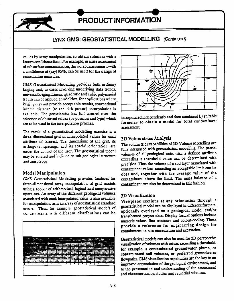
3D VisualizationViewplane sections at any orientation through ageostatistical model can be displayed in different formats,optionally overlayed on a geological model and/ortransformed project data Display format options includenumeric values, line contours and colour-coding. Theseprovide a reference for engineering design forcontaiment, in-situ remediation and excavation.
Geostatistical models can also be used for 3D perspectivevksualization of volumes with values ecceding a threshold,for ezample, a contaminated groundwater plume, orcontaminated soil volumes, or preferred groundwater
flowpaths. GMS visualzation capabilities are the key to animproved appreciation of the geological environment, andto the presentation and understanding of site assessmentand characterization studies and remedial solutions.
AEl"", �/1141141� 44t.141I - I I - � - I . I . i . I - I - I - I - I :
A-8
* I n
-I PRODUCT INFORMATION
LYNX GMS: ENGINEERING OTION (tba'y 1992)
GMS FEATURES
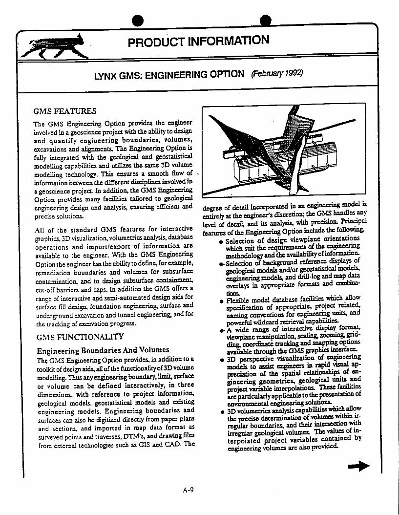
The GMS Engineering Option provides the engineer
involved in a geoscience project with the ability to design
and quantify engineering boundaries, volumes,
excavations and alignments. The Engineering Option is
fully integrated with the geological and geostatistical
modelling capabilities and utilzs the same 3D volume
modelling technology. This ensures a smooth flow of
information between the different disciplines involved in
a geoscience project. In addition, the GMS Engineering
Option provides many facilities tailored to geological
engineering design and analysis, ensuring efficient and
precise solutions.
All of the standard GMS features for interactive
graphics, 3D visualization, volumetrics analysis, database
operations and import/export of information are
available to the engineer. With the GMS Engineering
Option the engineer has the ability to define, for example,
remediation boundaries and volumes for subsurface
contamination, and to design subsurface containment,
cut-off barriers and caps. In addition the GMS offers a
range of interactive and semi-automated design aids for
surface fill design, foundation engineering, surface and
underground excavation and tunnel engineering, and for
the tracking of excavation progress.
GMS FUNCTIONALITY
Engineering Boundaries And Volumes
The GMS Engineering Option provides, in addition to a
toolkit of design aids, all of the functionality of 3D volume
modelling. Thus any engineering boundary, limit, surface
or volume can be defined interactively, in three
dimensions, with reference to project information,
geological models, geostatistical models and existing
engineering models. Engineering boundaries and
surfaces can also be digitized directly from paper plans
and sections, and imported in map data format as
surveyed points and traverses, DTM's, and drawing files
from external technologies such as GIS and CAD. The
I
degree of detail incorporated in an enging modl isentirely at the egineers discretion; the GMS handles anylevel of detail, and its analysis, with precision. Principalfeatures of the Engineering Option include the following
* Selection of design viewplane orientationswhich suit the requirements of the G gmethodology and the availabilit of information.
e- Selection of backgrountd reference displays ofgeological models and/or geostatistical models,engineerin models, and drill-log and map dataoverlays in appropriate formats and an
* Flexible model database facilities which alowspecification of appropriate, project related,naming conventions for e g units, and
powerful wildcard retrieval capabili. A wide range of interactive display format,
viewplane manipulation, scalin zooming grid-ding. coordinate tracking and snapping optionsavailable through the GMS graphics interface.
* 3D perspective visualization of engineeringmodels to assist engineers in rapid visual ap-pxwation of the spatial relationships of en-pneering geometries, geological units andproject variable interpolations. These facilitiesare particularly applicable to the presentation ofenvironmenta engineering solutions.
* 3D volumetrics analysis capabilities which allowthe precise determination of volumes within ir-regular boundaries, and their intersection withirregular geological volumes. The values of in-terpolated project variables contained byengineering volumes are also provided.
A-9

4h --
I LYNX GMS: ENGINEERING OPTION Conrnued)
* The availability of design templates which can
be interactively scaled, positioned, rotated
and incorporated into an engineering design.
* The ability to interactively edit engineeringmodels to allow for new project information,to create as many engineering models as re-
quired and to perform rapid evaluations and
comparisons of alternatives.* Printer, plotter and plotfile output of any
viewplane and perspective display, and export
of engineering information to external tech-
nologies via the GMS map file utilities.
Surface Engineering
The GMS Engineering Option provides interactive
facilities for the design of surface excavation and fill. The
algorithm utilizes a conical expansion technique which
handles irregular boundaries and interacts with
geological and topographical surfaces- The engineer can
apply a top-down or bottom-up approach to design and
has full control of design parameters such as slope angle
and berm width. These parameters can be varied by
sector, or domain, around the perimeter. The design
template facilities can be used to significant advantage in
the design of excavation and fill ramps. The result of this
exercise is a map defining the excavation or fill surface
and its intersection with topography. The GMS surface
handling facilities can be applied to creation of a
corresponding volume model for volumetrics analysis-
Simple excavation design for environmental remediation
is performed interactively on the viewplane and extended
to the third dimension, as in geological modellin. Te
geological modelling and excavation design capabilities of
the GMS are particularly applicable to heavy foundation
eginrig (C& hydr-ctric schemes) and large scale
highway excavation. If the Mengincering qualities of the
excavation materials have been defined in a geological
model then the results of a volumetrics analysis can lead
directly to excavation costing The GMS capabilities are
also applicable to the invetgation of natural geotechnical
hazards and excavation stability.
Underground & Tunnel Engineering
The GMS Engineering Option provides similar capabilities
for the design and modelling of complex underground
excavations. If geological structure and rock qualis have
been defined in geological and/or geostalistical models
then a volumetrics analysis can be applied to the estimation
and costing of excavation as well as rock reinforcemenL In
particular, the GMS offers a selection of interactive
egineering tools for tunnel, ramp and shaft design and
alignmenL The design template facilities can be used
efficiently in the determination of drill and blast patterns
Excavation ControlReduced survey information for surface and underground
excavations can be imported into project map files in the
form of survey traverses and points- The GMS provides
facilities for transforming this information interactively into
excavation surfaces and volumes. These can be overlayed
on excavation design information for reconciliation, and
analyzed volumetrically for contract payment purposes.
A-10

APPENDIX B
ATTENDEES AT THE NRC/DOE APPENDIX 7MEETING

* 16APPENDIX B
ATTENDEES AT THE NRC/DOE APPENDIX 7 MEETING
Denver, Colorado and Las Vegas, Nevada
August 10 - 11, 1993
August 10, 1993 - Denver, Colorado
David BrickeyDavid BueschDon Chery, Jr.Bob DickersonRon DrakeTracey J. FelgerJohn GauthierDaniel J. GockelBrett GracelyClay HunterSteve Le RoySteve McDuffieJim NelsonDarrell PorterChris RautmanArdyth SimmonsRick SpenglerGerry L. StirewaltJohn S. StucklessMark C. Tynan
EG&G/EMUSGSNRCSAICSAICSAIC/USGSM&OUSGSSAICUSGSM & O/Duke Eng.NRCSAICSAICSandiaDOE/YMPOUSGSCNWRAUSGSDOE/YMPO
(702) 794-7581(702) 794-7195(301) 504-3461(303) 279-7242(303) 273-1206(702) 794-7195(702) 794-1866(303) 236-1418(303) 279-7242(303) 236-1123(702) 794-7836(301) 504-3460(303) 273-1271(303) 236-0532(505) 844-4584(702) 794-7998(303) 236-1266(703) 979-9129(303) 236-7889(702) 794-7940
August 11, 1993 - Las Vegas, Nevada
Tom BjerstedtDavid BrickeyDon Chery, Jr.Tracey J. FelgerJohn GauthierSteve McDuffieArdyth SimmonsGerry L. StirewaltMark C. Tynan
DOE/YMPOEG&G/EMNRCSAIC/USGSM & ONRCDOE/YMPOCNWRADOE/YMPO
(702) 794-7581 A(301) 504-3461(702) 794-7195(702) 794-1866(301) 504-3460(702) 794-7998(703) 979-9129(702) 794-7940
B-i