Embed Size (px)
Citation preview

CAP 232
Aerodrome Survey Information
www.caa.co.uk
Safety Regulation Group


CAP 232
Aerodrome Survey Information
Safety Regulation Group
31 January 2008

CAP 232 Aerodrome Survey Information
© Civil Aviation Authority 2008
All rights reserved. Copies of this publication may be reproduced for personal use, or for use within acompany or organisation, but may not otherwise be reproduced for publication.
To use or reference CAA publications for any other purpose, for example within training material forstudents, please contact the CAA at the address below for formal agreement.
ISBN 978 0 11790 966 3
Edition 1, 1998Edition 2, August 2000Edition 3, March 2004Edition 3, Amendment 1, 31 January 2008
Enquiries regarding the content of this publication should be addressed to:Aeronautical Information Management Regulation, DAP, CAA House, 45-49 Kingsway, London, WC2B6TE
The latest version of this document is available in electronic format at www.caa.co.uk, where you mayalso register for e-mail notification of amendments.
Published by TSO (The Stationery Office) on behalf of the UK Civil Aviation Authority.
Printed copy available from: TSO, PO Box 29, Norwich NR3 1GN www.tso.co.uk/bookshopTelephone orders/General enquiries: 0870 600 5522 E-mail: [email protected]

CAP 232 Aerodrome Survey Information
Amendment Record
Amendment
NumberAmendment Date Incorporated by Incorporated on
01/2008 31 January 2008 CAA 31 January 2008

CAP 232 Aerodrome Survey Information
Amendment
NumberAmendment Date Incorporated by Incorporated on
CAP 232 Aerodrome Survey Information
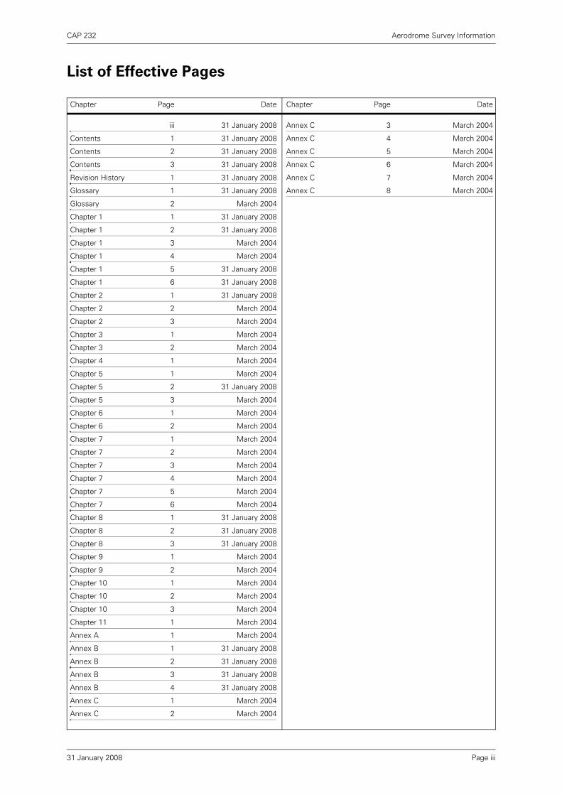
Chapter Page Date Chapter Page Date
Page iii
iii 31 January 2008
Contents 1 31 January 2008
Contents 2 31 January 2008
Contents 3 31 January 2008
Revision History 1 31 January 2008
Glossary 1 31 January 2008
Glossary 2 March 2004
Chapter 1 1 31 January 2008
Chapter 1 2 31 January 2008
Chapter 1 3 March 2004
Chapter 1 4 March 2004
Chapter 1 5 31 January 2008
Chapter 1 6 31 January 2008
Chapter 2 1 31 January 2008
Chapter 2 2 March 2004
Chapter 2 3 March 2004
Chapter 3 1 March 2004
Chapter 3 2 March 2004
Chapter 4 1 March 2004
Chapter 5 1 March 2004
Chapter 5 2 31 January 2008
Chapter 5 3 March 2004
Chapter 6 1 March 2004
Chapter 6 2 March 2004
Chapter 7 1 March 2004
Chapter 7 2 March 2004
Chapter 7 3 March 2004
Chapter 7 4 March 2004
Chapter 7 5 March 2004
Chapter 7 6 March 2004
Chapter 8 1 31 January 2008
Chapter 8 2 31 January 2008
Chapter 8 3 31 January 2008
Chapter 9 1 March 2004
Chapter 9 2 March 2004
Chapter 10 1 March 2004
Chapter 10 2 March 2004
Chapter 10 3 March 2004
Chapter 11 1 March 2004
Annex A 1 March 2004
Annex B 1 31 January 2008
Annex B 2 31 January 2008
Annex B 3 31 January 2008
Annex B 4 31 January 2008
Annex C 1 March 2004
Annex C 2 March 2004
Annex C 3 March 2004
Annex C 4 March 2004
Annex C 5 March 2004
Annex C 6 March 2004
Annex C 7 March 2004
Annex C 8 March 2004
31 January 2008
List of Effective Pages

INTENTIONALLY LEFT BLANK

CAP 232 Aerodrome Survey Information
Contents
List of Effective Pages iii
Revision History 1
Glossary of Terms 1
Chapter 1 Introduction
Preamble 1
Purpose 1
Survey Philosophy 1
Publication Structure 1
Mandatory Requirements 2
Survey Areas 2
Survey Periodicity 3
Survey Procedures 3
Data Management 3
Survey Declaration Form 4
Qualifying Surveying Companies. 4
Accuracy 5
Survey Package 5
Conversion Factors 6
Standard Documents 6
Guidance and Policy 6
Chapter 2 Survey Procedure
General 1
Horizontal Control 1
Vertical Control 1
Instrumentation 1
Methodology 2
Obstacles to be Heighted 2
Contents Page 131 January 2008

CAP 232 Aerodrome Survey Information
Chapter 3 Presentation
Plans 1
Survey Reports 2
Digital Data 2
Chapter 4 Quality Assurance
Quality Records 1
Methodology 1
Chapter 5 Aerodrome Plan Survey Area
Purpose 1
Survey Specification 1
Plan Content 1
Digital Data 2
Chapter 6 AGA Survey Area
Purpose 1
Survey Specification 1
Digital Data 2
Chapter 7 Dominant Obstacle Survey Areas
Purpose 1
Survey Specification 1
Digital Data 2
Chapter 8 Aerodrome Obstacle Chart - ICAO Type A Survey Area
Purpose 1
Survey Specification 1
Digital Data 2
Chapter 9 Precision Approach Procedure Survey Area
Purpose 1
Survey Specification 1
Digital Data 1
Contents Page 231 January 2008

CAP 232 Aerodrome Survey Information
Chapter 10 Precision Approach Terrain Chart Survey Area
Purpose 1
Survey Specification 1
Survey Chart Presentation 1
Published Chart 1
Chart Maintenance 2
Chapter 11 PAPI/APAPI Site Survey Area
Annex A Survey Declaration Form
Annex B Digital Data Specification
Annex C Methodology of Modelling Obstacles (For information only)
Introduction 1
Description of Artificial Obstacles 1
Simple Obstacle Modelling 1
Sophisticated Obstacle Modelling 1
Considerations on Accuracy 2
Contents Page 331 January 2008

INTENTIONALLY LEFT BLANK

CAP 232 Aerodrome Survey Information
Revision History Page 1
Revision History
Edition 1 1998
CAP 232 was fundamentally revised in 1998 to reflect the adoption by ICAO of the WorldGeodetic System of 1984 (WGS-84). WGS-84 is the geodetic reference system for allaeronautical data.
Edition 2 August 2002
This edition contains no technical changes but reflects the change in publisher name fromWestward Digital Limited to Documedia Solutions Limited.
Edition 3 March 2004
This edition contains no technical changes but reflects the change in publisher name fromDocumedia Solutions Limited to TSO (The Stationery Office).
Edition 3, Amendment 1 January 2008
In Chapter 8: Aerodrome Obstacle Chart – ICAO Type A Survey Area, the requirements havebeen revised to reflect the elimination of UK differences to ICAO Annex 4, Chapter 3:Aerodrome Obstacle Chart – ICAO Type A (Operating Limitations). Also, the CAA addressdetails on the Inside Front Cover have been revised.
31 January 2008

INTENTIONALLY LEFT BLANK

CAP 232 Aerodrome Survey Information
Glossary of Terms
Above Mean Sea Level
(AMSL)
Orthometric Height
Accelerate-Stop Distance
Available (ASDA)
The length of the take-off run available plus the length of the stopway, if provided. (ICAO Annex 14)
Aerodrome Elevation The elevation of the highest point of the landing area. (ICAO Annex 4)
Aerodrome Reference Point (ARP)
The designated geographical location of an aerodrome. (ICAO Annex 4)
AGA Aerodromes, Air Routes and Ground Aids (ICAO Definition)
Cyclic Redundancy Check
(CRC)A mathematical algorithm applied to the digital expression of data that provides a level of assurance against loss or alteration of data. (ICAO Annex 14)
Ellipsoid Height The height related to the reference ellipsoid, measured along the ellipsoidal outer normal through the point in question. (ICAO Annex 14)
Geoid The equipotential surface in the gravity field of the Earth which coincides with the undisturbed mean sea level (MSL) extended continuously through the continents. (ICAO Annex 14)
Landing Area That part of a movement area intended for the landing or take-off of aircraft. (ICAO Annex 4)
Landing Distance Available
(LDA)
The length of landing distance available (ICAO Annex 14)
Obstacle All fixed (whether temporary or permanent) and mobile objects, or parts thereof, that are located on an area intended for the surface movement of aircraft or that extend above a defined surface intended to protect aircraft in flight. (ICAO Annex 14)
Orthometric Height Height of a point related to the geoid, generally presented as a MSL elevation. (ICAO Annex 14)
Reference Ellipsoid A geometric figure, usually determined by rotating an ellipse about its shorter (polar) axis, used as a surface of reference for geodetic surveys. The reference ellipsoid closely approximates to the dimensions of the geoid, with certain ellipsoids fitting the geoid more closely for various areas of the earth.(Non ICAO)
Survey Date The date that fieldwork was carried out to obtain data for the survey. Where fieldwork was completed over more than one day the end date of fieldwork shall be used.
Glossary Page 131 January 2008

CAP 232 Aerodrome Survey Information
Take-off Distance Available
(TODA)
The length of the take-off run available plus the length of the clearway if provided. (ICAO Annex 14)
Take off Run Available (TORA) The length of the take-off run available (ICAO Annex 14)
Threshold The beginning of that portion of the runway usable for landing. (ICAO Annex 4)
Glossary Page 2March 2004
CAP 232 Aerodrome Survey Information
Chapter 1 Introduction
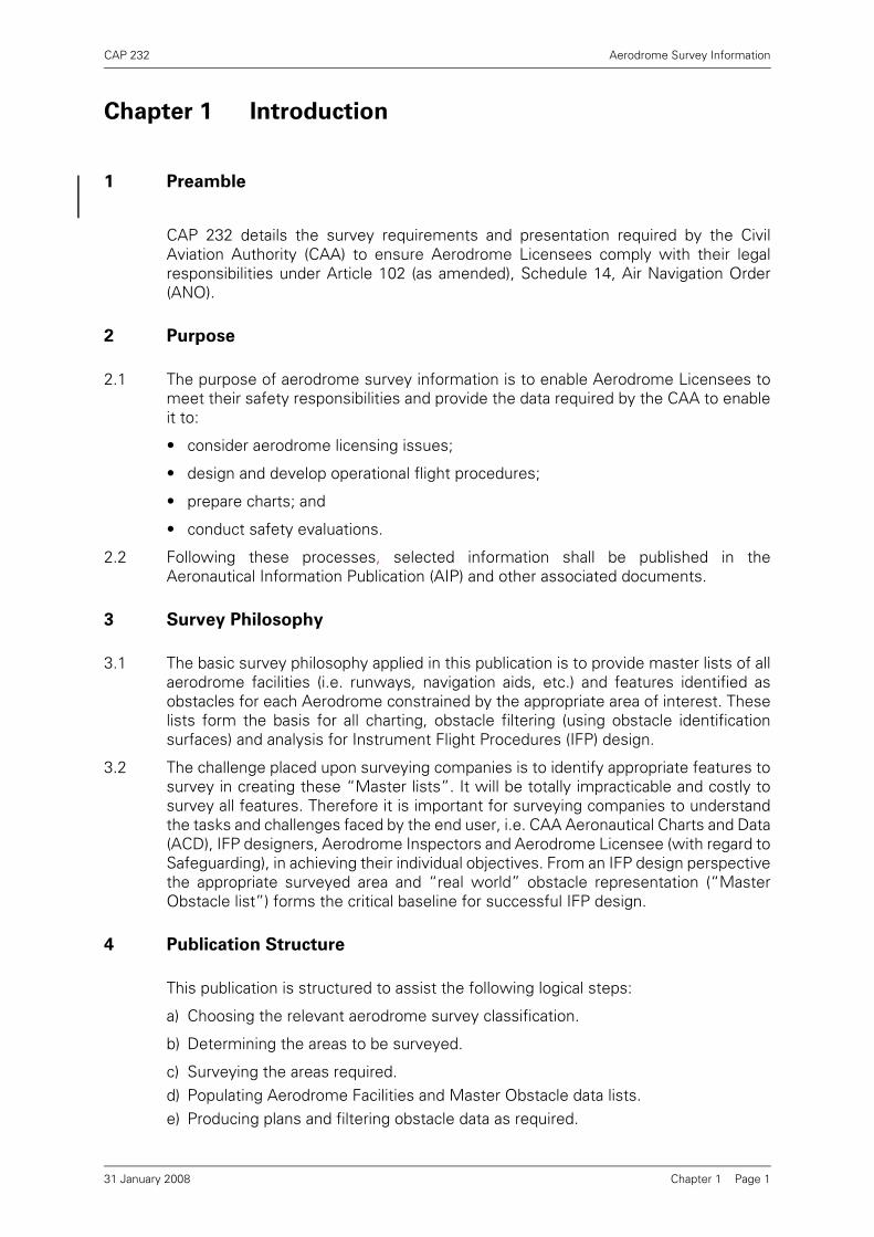
1 Preamble
CAP 232 details the survey requirements and presentation required by the CivilAviation Authority (CAA) to ensure Aerodrome Licensees comply with their legalresponsibilities under Article 102 (as amended), Schedule 14, Air Navigation Order(ANO).
2 Purpose
2.1 The purpose of aerodrome survey information is to enable Aerodrome Licensees tomeet their safety responsibilities and provide the data required by the CAA to enableit to:
• consider aerodrome licensing issues;
• design and develop operational flight procedures;
• prepare charts; and
• conduct safety evaluations.
2.2 Following these processes, selected information shall be published in theAeronautical Information Publication (AIP) and other associated documents.
3 Survey Philosophy
3.1 The basic survey philosophy applied in this publication is to provide master lists of allaerodrome facilities (i.e. runways, navigation aids, etc.) and features identified asobstacles for each Aerodrome constrained by the appropriate area of interest. Theselists form the basis for all charting, obstacle filtering (using obstacle identificationsurfaces) and analysis for Instrument Flight Procedures (IFP) design.
3.2 The challenge placed upon surveying companies is to identify appropriate features tosurvey in creating these “Master lists”. It will be totally impracticable and costly tosurvey all features. Therefore it is important for surveying companies to understandthe tasks and challenges faced by the end user, i.e. CAA Aeronautical Charts and Data(ACD), IFP designers, Aerodrome Inspectors and Aerodrome Licensee (with regard toSafeguarding), in achieving their individual objectives. From an IFP design perspectivethe appropriate surveyed area and “real world” obstacle representation (“MasterObstacle list”) forms the critical baseline for successful IFP design.
4 Publication Structure
This publication is structured to assist the following logical steps:
a) Choosing the relevant aerodrome survey classification.
b) Determining the areas to be surveyed.
c) Surveying the areas required.d) Populating Aerodrome Facilities and Master Obstacle data lists.e) Producing plans and filtering obstacle data as required.
Chapter 1 Page 131 January 2008

CAP 232 Aerodrome Survey Information
f) Producing a survey report.g) Distributing relevant data and information.
5 Mandatory Requirements
5.1 This publication strives to minimise the cost to Aerodromes while providing theminimum prescribed safety standards and requirements. The CAA fully recognisesthat each individual Aerodrome governs its own operational needs and therefore thelevel of survey required should be appropriate and economical to the type of operationintended for its purpose.
5.2 Aerodrome Licensees shall provide accurate survey information of their aerodromeand environs according to the type of operation identified by aerodrome surveyclassification and survey areas required as prescribed in Table 1 and shall be carriedout to measure any changes at the periodic intervals as set out in Table 2.
6 Survey Areas
The Survey Areas required for a particular Aerodrome Survey Classification areprescribed in Table 1.
Table 1 Aerodrome Survey Classification and Survey Areas Required
Type of OperationAerodrome Survey
Classification
Aerodrome with no Instrument Flight Procedures (IFP) 1Aerodrome with Non-precision IFP 2Aerodrome with Precision ILS CAT I or equivalent IFP 3Aerodrome with Precision ILS CAT II/III or equivalent IFP 4
Survey Area ReferenceAerodrome Classification
1 2 3 4
Aerodrome Plan Chapter 5AGA Chapter 6Non-precision Instrument Approach (*)
Chapter 7
Visual Manoeuvring (Circling) Chapter 7Departure (#) Chapter 7Aerodrome Obstacle Chart - Type A (~)
Chapter 8
Precision Approach Procedure
Chapter 9
Precision Approach Terrain Chart
Chapter 10
(*) Only required for aerodrome classification 3 and 4 if runways have additional Non-precision IFP.
(#) Only applicable to runways from which IFR departures take place.(~) Only required if runways used by Performance A aeroplanes engaged in Public
Transport flights.
Chapter 1 Page 231 January 2008

CAP 232 Aerodrome Survey Information
7 Survey Periodicity
Surveys shall be undertaken for all Survey Areas required to measure any changes atthe periodic intervals prescribed in Table 2.
8 Survey Procedures
8.1 Geodetic Connection
• The procedures for a geodetic connection are detailed in Chapter 2.
• The geodetic connection date shall be included with the submission of a SurveyDeclaration Form (see Annex A).
8.2 Full Survey
• The procedures for a full survey are detailed in Chapter 2.
• All full surveys shall be notified by the submission of a Survey Declaration Form(see Annex A).
8.3 Check Survey
• The annual check survey is to identify any changes, including significant treegrowth or reduction, since the previous survey. Any change shall be surveyed tothe specifications detailed in this publication.
• All check surveys shall be notified by the submission of a Survey Declaration Form(see Annex A)
9 Data Management
9.1 Proper data management is crucial during the entire survey and subsequentdeclaration process. Survey companies are urged to implement rigorous datahandling processes and practices to eliminate erroneous data submission. Eachsurveyed entity and associated attributes shall be dealt with as a single data record
Table 2 Survey Periodicity
Survey Type Aerodrome Classification Periodicity
Geodetic Connection 2, 3 and 4 1. Together with an initial full survey.
2. When a more accurate reference frame for WGS-84 becomes available.
Full Survey 1, 2, 3 and 4 1. Initial survey.
2. If a check survey is not carried out annually.
3. If any doubt exists as to the validity of a previous survey.
Check Survey 1, 2, 3 and 4 1. Annually after a full survey.
Chapter 1 Page 3March 2004
CAP 232 Aerodrome Survey Information
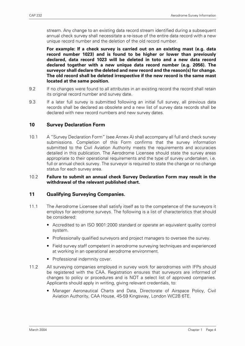
stream. Any change to an existing data record stream identified during a subsequentannual check survey shall necessitate a re-issue of the entire data record with a newunique record number and the deletion of the old record number.
For example: If a check survey is carried out on an existing mast (e.g. data
record number 1023) and is found to be higher or lower than previously
declared, data record 1023 will be deleted in toto and a new data record
declared together with a new unique data record number (e.g. 2056). The
surveyor shall declare the deleted and new record and the reason(s) for change.
The old record shall be deleted irrespective if the new record is the same mast
located at the same position.
9.2 If no changes were found to all attributes in an existing record the record shall retainits original record number and survey date.
9.3 If a later full survey is submitted following an initial full survey, all previous datarecords shall be declared as obsolete and a new list of survey data records shall bedeclared with new record numbers and new survey dates.
10 Survey Declaration Form
10.1 A “Survey Declaration Form” (see Annex A) shall accompany all full and check surveysubmissions. Completion of this Form confirms that the survey informationsubmitted to the Civil Aviation Authority meets the requirements and accuraciesdetailed in this publication. The Aerodrome Licensee should state the survey areasappropriate to their operational requirements and the type of survey undertaken, i.e.full or annual check survey. The surveyor is required to state the change or no changestatus for each survey area.
10.2 Failure to submit an annual check Survey Declaration Form may result in the
withdrawal of the relevant published chart.
11 Qualifying Surveying Companies.
11.1 The Aerodrome Licensee shall satisfy itself as to the competence of the surveyors itemploys for aerodrome surveys. The following is a list of characteristics that shouldbe considered:
• Accredited to an ISO 9001:2000 standard or operate an equivalent quality controlsystem.
• Professionally qualified surveyors and project managers to oversee the survey.
• Field survey staff competent in aerodrome surveying techniques and experiencedat working in an operational aerodrome environment.
• Professional indemnity cover.
11.2 All surveying companies employed in survey work for aerodromes with IFPs shouldbe registered with the CAA. Registration ensures that surveyors are informed ofchanges to policy or procedures and is NOT a select list of approved companies.Applicants should apply in writing, giving relevant credentials, to:
• Manager Aeronautical Charts and Data, Directorate of Airspace Policy, CivilAviation Authority, CAA House, 45-59 Kingsway, London WC2B 6TE.
Chapter 1 Page 4March 2004
CAP 232 Aerodrome Survey Information
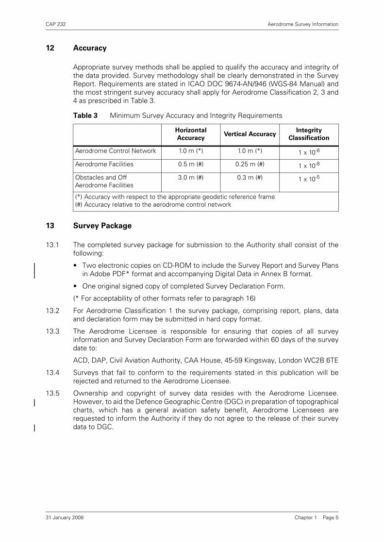
12 Accuracy
Appropriate survey methods shall be applied to qualify the accuracy and integrity ofthe data provided. Survey methodology shall be clearly demonstrated in the SurveyReport. Requirements are stated in ICAO DOC 9674-AN/946 (WGS-84 Manual) andthe most stringent survey accuracy shall apply for Aerodrome Classification 2, 3 and4 as prescribed in Table 3.
13 Survey Package
13.1 The completed survey package for submission to the Authority shall consist of thefollowing:
• Two electronic copies on CD-ROM to include the Survey Report and Survey Plansin Adobe PDF* format and accompanying Digital Data in Annex B format.
• One original signed copy of completed Survey Declaration Form.
(* For acceptability of other formats refer to paragraph 16)
13.2 For Aerodrome Classification 1 the survey package, comprising report, plans, dataand declaration form may be submitted in hard copy format.
13.3 The Aerodrome Licensee is responsible for ensuring that copies of all surveyinformation and Survey Declaration Form are forwarded within 60 days of the surveydate to:
ACD, DAP, Civil Aviation Authority, CAA House, 45-59 Kingsway, London WC2B 6TE
13.4 Surveys that fail to conform to the requirements stated in this publication will berejected and returned to the Aerodrome Licensee.
13.5 Ownership and copyright of survey data resides with the Aerodrome Licensee.However, to aid the Defence Geographic Centre (DGC) in preparation of topographicalcharts, which has a general aviation safety benefit, Aerodrome Licensees arerequested to inform the Authority if they do not agree to the release of their surveydata to DGC.
Table 3 Minimum Survey Accuracy and Integrity Requirements
Horizontal
AccuracyVertical Accuracy
Integrity
Classification
Aerodrome Control Network 1.0 m (*) 1.0 m (*) 1 x 10⁻⁸
Aerodrome Facilities 0.5 m (#) 0.25 m (#) 1 x 10⁻⁸
Obstacles and Off Aerodrome Facilities
3.0 m (#) 0.3 m (#) 1 x 10⁻⁵
(*) Accuracy with respect to the appropriate geodetic reference frame(#) Accuracy relative to the aerodrome control network
Chapter 1 Page 531 January 2008

CAP 232 Aerodrome Survey Information
14 Conversion Factors
ICAO Annex 5 is used as the standard for the application of all conversion factors.
15 Standard Documents
• ICAO DOC 9674-AN/946 (WGS-84 Manual)
• ICAO Annex 4 (Aeronautical Charts)
• ICAO Annex 5 (Units of Measurement to be Used in Air and Ground Operations)
• ICAO Annex 14 (Aerodromes)
• ICAO Annex 15 (Aeronautical Information Services)
• ICAO DOC 8168 - OPS/611(PANS OPS)
• Air Navigation: the Order and the Regulations CAP 393
• Licensing of Aerodromes CAP 168
• Safeguarding of Aerodromes CAP 738
• EUROCONTROL Doc CHAIN/0028 (Integrity of Aeronautical Information Principles– Data and Quality Management)
16 Guidance and Policy
For guidance and policy on points that are not covered within this publication adviceshould be sought from DAP, CAA House, 45-59 Kingsway, London WC2B 6TE.
Non-SI Units SI Units
1 Nautical Mile (nm) 1.852 kilometres (km)
0.54 nm 1 km
1 Foot (ft) 0.3048 metres (m)
3.2808 ft 1 m
1nm = 6076.04 ft
Chapter 1 Page 631 January 2008

CAP 232 Aerodrome Survey Information
Chapter 2 Survey Procedure
1 General
1.1 The accuracy and integrity requirements for the geodetic connection and surveyeddata are stated in Table 3.
1.2 Surveyed data that does not meet the accuracy and integrity requirements isunacceptable for IFP design and will be published in the AIP with an asterisk.Aerodromes without Instrument Flight Procedures do NOT need to undertakesurveys to the accuracy and quality assurance requirements stated in the ICAO DOC9674-AN/946 (WGS-84 Manual). The Aerodrome Licensee is responsible for ensuringthe accuracy of information required for Aerodrome Plan and AGA survey areas. It isrecommended that a surveyor or suitably experienced person provide the plans anddata.
2 Horizontal Control
2.1 Co-ordinates will be required in WGS-84 format (required format for published data)and appropriate National Grid (for plotting and design on topographical charts).
2.2 Survey control points shall conform to the ICAO DOC 9674-AN/946 (WGS-84Manual).
2.3 WGS-84 geodetic control and format requires that the methods deployed must provethat the accuracy for the various surveys has been met. Survey companiesundertaking these surveys shall be responsible for the accuracy of the control dataand any transformation sets used. An analysis of the accumulated error, evidenceconfirming the required accuracies have been met and the transformation parametersused shall be included in the Survey Report.
3 Vertical Control
3.1 Orthometric and ellipsoidal elevations are required.
3.2 The variable separation between the geoid and the reference ellipsoid may give riseto inaccuracies greater than the allowable specified. For the computation to transformellipsoidal to orthometric elevations a geoid model should be used. If a geoid modelis not available extra care must be taken to ensure good geometry of the initial controlpoints. In all cases appropriate survey checks shall be applied to prove the quality ofvertical control. These checks shall be included within the survey report.
3.3 Standard survey practice shall be used to produce the elevation to the requiredspecification accuracy and the integrity of the control points used shall be proved.
4 Instrumentation
All survey equipment shall have a current calibration certificate and be able to performto the accuracy appropriate to the requirements of the surveys.
Chapter 2 Page 131 January 2008
CAP 232 Aerodrome Survey Information
5 Methodology
5.1 All permanent controls that are established within the aerodrome boundary shall bedocumented and traceable.
5.2 Office appreciation using contour maps can aid in the process of defining the probableextent of the survey and the likely position of obstacles. Local scale factor adjustmentto ground distances shall be considered, and the effects of curvature and refraction.
5.3 New obstacle data shall be proved by two independent measurements and theirresultant elevations and positions shall satisfy the appropriate survey criteria.
5.4 Obstacles heighted on previous surveys need only to be checked to confirm theirheight and position without the rigour afforded to new obstacles. Particular attentionshould be paid to structures and trees whose height may change. An appreciation ofthe effects of vertical angles over variable distances is necessary to give good heightaccuracies. It is recommended that observations taken without corrections forcurvature and refraction should be limited to a maximum of 1 km.
6 Obstacles to be Heighted
6.1 Surveying companies should take note that when surveying a prescribed area, asituation might arise where the highest obstacle within that area might notnecessarily be the dominant obstacle for that particular phase of flight. Therefore,surveyors should always declare an obstacle in the Master Obstacle list if any doubtexists to its validity as an obstacle.
6.2 Obstacles include terrain, vegetation and structures.
6.3 Where there are a large number of obstacles to be heighted it will be impractical tosurvey, for example, every tree in a wooded area and therefore the surveyor shouldconsult with the Aerodrome Licensee and the Instrument Flight Procedure (IFP)designers where necessary.
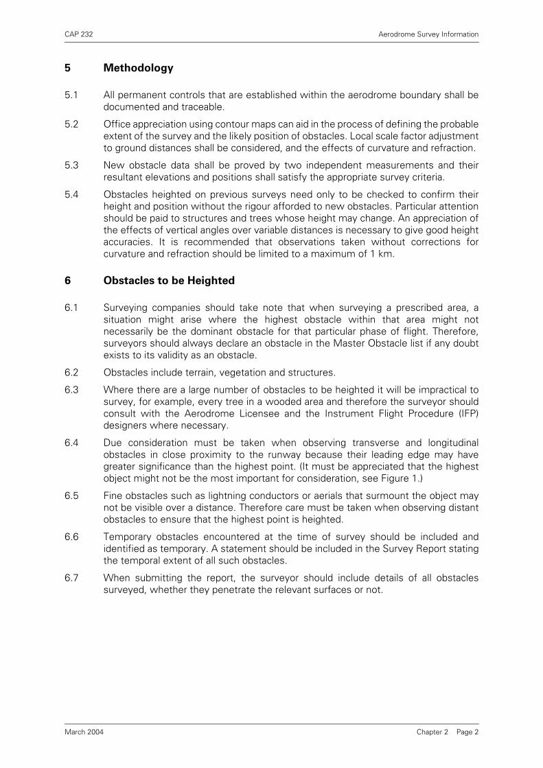
6.4 Due consideration must be taken when observing transverse and longitudinalobstacles in close proximity to the runway because their leading edge may havegreater significance than the highest point. (It must be appreciated that the highestobject might not be the most important for consideration, see Figure 1.)
6.5 Fine obstacles such as lightning conductors or aerials that surmount the object maynot be visible over a distance. Therefore care must be taken when observing distantobstacles to ensure that the highest point is heighted.
6.6 Temporary obstacles encountered at the time of survey should be included andidentified as temporary. A statement should be included in the Survey Report statingthe temporal extent of all such obstacles.
6.7 When submitting the report, the surveyor should include details of all obstaclessurveyed, whether they penetrate the relevant surfaces or not.
Chapter 2 Page 2March 2004
CA
P 232
Aerodrom
e Survey Inform
ation
Chapter 2 P
age 3
Suggestedsurvey points
March 2004
Figure 1 Transverse and Longitudinal Obstacles
ThresholdRunway

INTENTIONALLY LEFT BLANK
CAP 232 Aerodrome Survey Information
Chapter 3 Presentation
1 Plans
1.1 The format of the base mapping for the Aerodrome Plan is at the discretion of theAerodrome Licensee. Listed below are the formats accepted by CAA:
• Digital mapping (see Chapter 1, paragraph 13).
• Hard copy mapping compilations.
• Published mapping sheets.
• or approved equivalent.
1.2 Surveyors shall ensure the following:
• The most recent mapping shall be used.
• National Grid reference system shall be shown with grid values along the planedge at convenient intervals.
• Data reference source and revision data shall be shown on the plan.
• Copyright licence requirements shall be met when required.
1.3 Plan Sheet Size
It is recommended that the sheet size should be limited to A0 size for easy storageand handling. Where this is not practical due to the extent of the survey area, out-sizeand adjoining sheets may be used. When using an adjoining sheet system, it shouldbe capable of being abutted and orientated to give the most economical coverage.
1.4 Plan Sheet Layout
1.4.1 Where multi-sheets are used, full reference shall be given to the total number in theseries.
1.4.2 Each sheet shall have a title panel. The information shown should consist of thefollowing:
• Aerodrome
• Drawing Title
• Drawing number or reference number including current amendment status.
• Date of survey
• Scale
• Survey company name and address including telephone number
• Surveyed by
• Checked by
• Sheet number
• Sheet lay-out and diagram, if applicable
• Abbreviations used
• A reference to the appropriate survey report
• Statement of vested copyright
Chapter 3 Page 1March 2004

CAP 232 Aerodrome Survey Information
2 Survey Reports
2.1 Geodetic Connection Report (if required)
Shall include the following:
• Quality Records as per Chapter 4, paragraph 1
• Details of the connection of the aerodrome control network to the geodeticnetwork
• Aerodrome control network plan
• Survey stations descriptions
• Transformation parameters
2.2 Full Survey Report
Shall include the following:
• Quality Records as per Chapter 4, paragraph 1
• Survey Declaration Form - Annex A
2.3 Check Survey Report
Shall include the following:
• Abbreviated Quality Records that refer back to the previous Full Survey with regardto surveying methodology
• Survey Declaration Form - Annex A
• Schedules listing all obstacles that have been added or deleted since the lastsurvey (see Chapter 3, paragraph 2.5)
2.4 For traceability purposes the complete documentation shall be reissued on everyoccasion that a check survey amends the preceding full or check survey.
2.5 Format of the schedules listing changes shall be at the discretion of the surveyor oras agreed with the Aerodrome Licensee. It is recommended that schedules areprepared as digital spreadsheets. To enable users to track changes where an obstaclehas been given a new feature number the old number shall be referenced against it.
3 Digital Data
3.1 The following master files of all surveyed obstacles and aerodrome facilities shall becreated and supplied in Annex B format:
a) Master obstacles file, named appropriately, e.g. egxx_obst00.crc ("egxx" is theICAO indicator code for the surveyed aerodrome and "00" is the year of the survey).To include:
• All features identified as obstacles.
b) Aerodrome facilities file, named appropriately, e.g. egxx_ad00.crc ("egxx" is theICAO indicator code for the surveyed aerodrome and "00" is the year of the survey).To include:
• All facilities surveyed for the purposes of the Aerodrome Plan survey area.
3.2 The integrity of the survey information supplied in digital format (see Annex B) shallbe protected against third party corruption by wrapping with a Cyclic RedundancyCheck (CRC). A 32 bit CRC-32Q algorithm value (CRCV format = Hexadecimal) isprovided by Eurocontrol DQTS CRC Tool, for further information contact ACD, DAP,CAA. CRC wrapping is mandatory for all survey data Annex B format files.
Chapter 3 Page 2March 2004

CAP 232 Aerodrome Survey Information
Chapter 4 Page 1
Chapter 4 Quality Assurance
1 Quality Records
1.1 All data elements for aerodromes with Instrument Flight Procedures shall betraceable to their source of production by an unbroken audit trail. The surveyingcompany, following guidance given in the WGS-84 Quality Assurance Manual, shallprovide information on the source of production in the form of Quality Records.
1.2 Quality Records shall include:
• Surveying organisation
• Name of surveyor(s)
• Date and purpose of survey
• Method of survey and equipment used
• Equipment calibration information and method of checking the survey
• Evidence that the accuracy requirements have been met including details of theerror budget analysis.
2 Methodology
The surveying company shall maintain an effective checking system to ensure thatthe data collected conforms to the accuracy standard and shall present proof of thatconformity within the Survey Report.
March 2004

INTENTIONALLY LEFT BLANK

CAP 232 Aerodrome Survey Information
Chapter 5 Aerodrome Plan Survey Area
1 Purpose
The Aerodrome Plan is part of the Aerodrome Manual which licensees are requiredto maintain for licensing and safeguarding purposes. The Aerodrome Plan is a workingdocument that gives an accurate picture of the aerodrome configuration and integralfacilities.
2 Survey Specification
2.1 The survey specification for the Aerodrome Plan is covered in ICAO DOC 9674 - AN/946 1st Edition 1997(WGS 84 Manual). Licensees of Aerodromes without InstrumentFlight Procedures see Chapter 2, paragraph 1.
2.2 All features listed at Chapter 5, paragraph 3.5 shall be surveyed.
3 Plan Content
3.1 The scale shall be 1:2500. The accepted format of the plan is covered in Chapter 3paragraph 1.1.
3.2 The area of the plan shall show the limits of the aerodrome boundary and thelocations of installations that are considered integral to the operational procedures ofthe aerodrome. Insets may be required to show off-site facilities.
3.3 All aerodrome characteristics as described in CAP 168 (Licensing of Aerodromes) andrelevant buildings shall be shown on the plan. Surveyed features shall be representedby an appropriate symbol and labelled by survey identification number. Theoperational runway(s) shall be shown by a solid line, the runway markings andapproach lighting arrays shall be shown true to scale.
3.4 The height above local ground level (AGL) and elevation AMSL to the highest point ofthe feature in metres and feet are required for all features surveyed that are greaterthan 0.9m above local ground level within the runway strip.
3.5 WGS 84 and OSGB36 co-ordinates and orthometric elevation AMSL and height AGL(where applicable) shall be shown on the plan for the following features.
• Aerodrome Beacon (Identification or Location)
• Aerodrome Elevation
• Aircraft stand points
• Anemometer(s)
• ARP
• ATC tower
• DME
• End of ASDA
• End of LDA
• End of TODA
Chapter 5 Page 1March 2004

CAP 232 Aerodrome Survey Information
• End of TORA
• ILS Localizer and Glidepath antennae
• ILS Middle and Outer Markers (where applicable show as inset on plan)
• IRVR
• MLS Azimuth and Elevation antennae
• NDB(Locator)
• PAPI/APAPI
• Radar antenna
• Runway Observing Position (ROP)
• Runway centre-line elevation points
• Runway edge lights if human observed RVR is in use
• Start of TORA
• Taxi-Holding positions
• Thresholds
• TLOF
• UHF and VHF transmitters
• VDF
• VOR
• Windsleeve(s)
3.6 The co-ordinates and associated data shall be in a schedule format within the marginof the plan (see Figure 2).
3.7 Additional information may be required; this shall be at the request of the AerodromeLicensee and may include the following:
• Fire service accommodation
• Emergency access/egress gates and routes
• Emergency water supply tanks
• Facility safeguarding (fences)
• ROP to runway edge lights distances (see CAP 168 for guidance)
• Human Observed RVR Conversion Table (see CAP 746 for specimen)
4 Digital Data
All surveyed features shall form part of the 'Aerodrome Facilities listing' depicted inAnnex B.
Chapter 5 Page 231 January 2008

CA
P 232
Aerodrom
e Survey Inform
ation
Chapter 5 P
age 3
66
107107
108108
110110
109109
6
107
108
110
312312 313313 314314312 313 314
109
SCHEDULE OF FEATURES
No. Feature WGS84 co-ordinates AOD AGL8001 03 END OF TODA 533501.40N 0002039.60W 21.40m
8002 21 START OF TORA 533500.90N 0002040.00W 21.60m
8003 03 END OF TORA 533457.10N 0002042.60W 22.20m
8004 21 THRESHOLD 533453.52N 0002045.08W 22.60m
8005 WINDSLEEVE 533452.30N 0002037.50W 26.00m 4.00m
8006 WATCHMAN RADAR 533449.40N 0002028.60W 34.00m 10.60m
8007 STAND 8 533453.60N 0002101.40W 23.30m
8008 STAND 16 533455.50N 0002058.90W 23.20m
8009 STAND 3 533455.80N 0002055·40W 22.50m
8010 STAND 4 533457.00N 0002057·50W 22.40m
8011 ATC CENTRE OF CUPOLA 533459.30N 0002054·30W 34.75m 12.75m
March 2004
Figure 2 Extract of Part of an Aerodrome Plan
212121
105105
1010
105
10
305305 306306 307307 308308 309309 310310 311311305 306 307 308 309 310 311
800180018001
8002
8003
80048007 8008
8009
8011
8010
8005
800780078006

INTENTIONALLY LEFT BLANK
CAP 232 Aerodrome Survey Information
Chapter 6 AGA Survey Area
1 Purpose
1.1 The purpose of the AGA survey is to identify all obstacles that infringe the prescribedAGA obstacle limitation surfaces appropriate to the existing or proposed runwaycoding.
1.2 The survey data enables the Aerodrome Licensee to make safety evaluations andassists the CAA to make assessments for the grant, retention or modification of anAerodrome Licence.
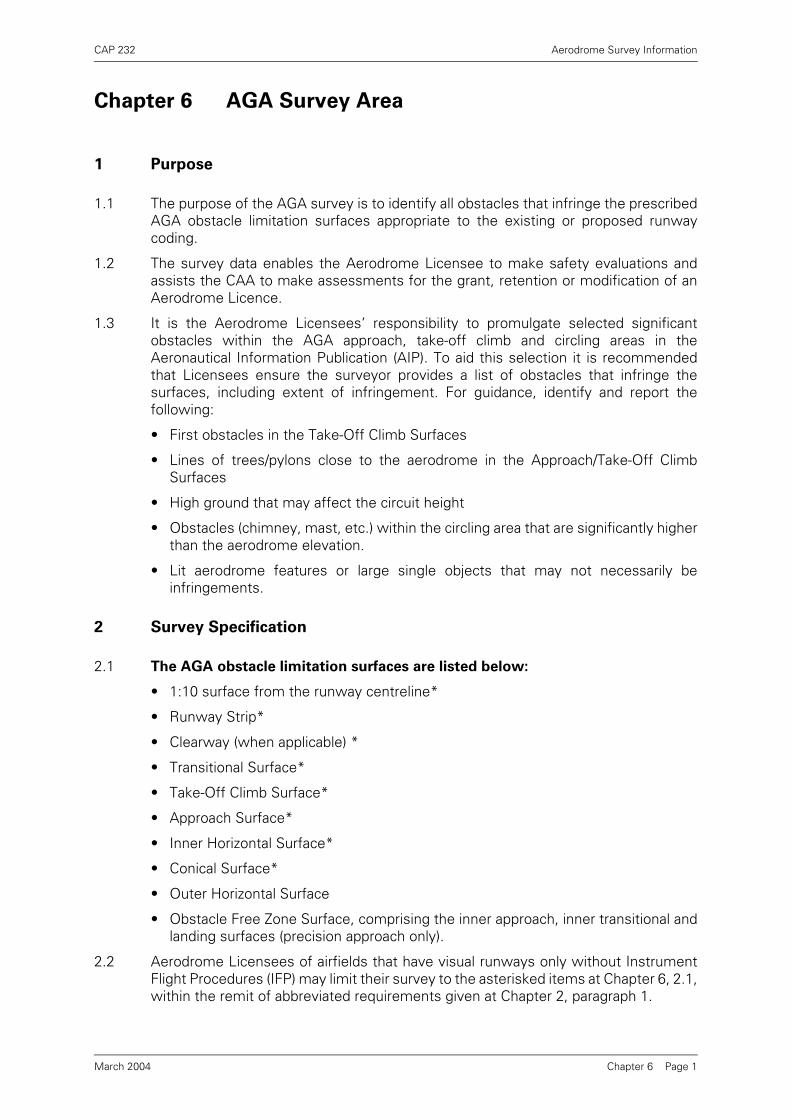
1.3 It is the Aerodrome Licensees’ responsibility to promulgate selected significantobstacles within the AGA approach, take-off climb and circling areas in theAeronautical Information Publication (AIP). To aid this selection it is recommendedthat Licensees ensure the surveyor provides a list of obstacles that infringe thesurfaces, including extent of infringement. For guidance, identify and report thefollowing:
• First obstacles in the Take-Off Climb Surfaces
• Lines of trees/pylons close to the aerodrome in the Approach/Take-Off ClimbSurfaces
• High ground that may affect the circuit height
• Obstacles (chimney, mast, etc.) within the circling area that are significantly higherthan the aerodrome elevation.
• Lit aerodrome features or large single objects that may not necessarily beinfringements.
2 Survey Specification
2.1 The AGA obstacle limitation surfaces are listed below:
• 1:10 surface from the runway centreline*
• Runway Strip*
• Clearway (when applicable) *
• Transitional Surface*
• Take-Off Climb Surface*
• Approach Surface*
• Inner Horizontal Surface*
• Conical Surface*
• Outer Horizontal Surface
• Obstacle Free Zone Surface, comprising the inner approach, inner transitional andlanding surfaces (precision approach only).
2.2 Aerodrome Licensees of airfields that have visual runways only without InstrumentFlight Procedures (IFP) may limit their survey to the asterisked items at Chapter 6, 2.1,within the remit of abbreviated requirements given at Chapter 2, paragraph 1.
Chapter 6 Page 1March 2004
CAP 232 Aerodrome Survey Information
2.3 The Aerodrome Licensee before the start of work will give the origin of each surface,relative to a particular runway, to the surveyor.
2.4 The dimensions and slopes of the various surfaces are defined and illustrated in CAP168.
2.5 The survey requirement is to height all obstacles within the AGA obstacle limitationsurfaces area that infringe the limitation surfaces.
2.6 Special care must be exercised in the near environs of the approach and take-off climbarea to ensure complete obstacle coverage.
3 Digital Data
All surveyed obstacles shall form part of the “Master Obstacles listing” depicted inAnnex B.
Chapter 6 Page 2March 2004

CAP 232 Aerodrome Survey Information
Chapter 7 Dominant Obstacle Survey Areas
1 Purpose
The purpose is to provide obstacle information for the applications listed below:
• Non-Precision Instrument Approach Procedures as follows:
Surveillance Radar - termination range 0.5, 1 and 2 nautical milesNDB (Non-directional Radio Beacon)VOR (VHF Omni directional Radio Range)ILS Localiser / MLS Azimuth only
• Visual Manoeuvring (Circling) Areas.
• Departure Areas 1 and 2.
2 Survey Specification
2.1 Non-Precision Instrument Approach Area
2.1.1 The survey area is divided into a mosaic of tiles as illustrated in Figure 3. The optimumtile size is 0.5 km x 1 km. However, the Aerodrome Licensee may select a tiledimension larger than the optimum after consultation with TA, DAP. The total areahas been designed to allow the IFP designer the flexibility to adjust the approach andmissed-approach path to gain the best operational advantage in terms of OCH withregard to the local terrain and/or airspace restrictions, against the design criteria laiddown in PANSOPS Vol II.
2.1.2 The optimum requirement is to height the three highest obstacles in each tile, thusallowing the IFP designer to calculate the most advantageous Minimum DescentAltitude/Height (MDA/H). However, in analysing the three highest obstacles in anyone tile, consideration must be given to other obstacles within the same tile wheresuch additional obstacles are located closer to the nominal flight path of an aircraftapproaching or departing an aerodrome. For example, if there were three chimneysadjacent to each other near the outer edge of the tile furthest from the nominal flightpath and there was an office building located within the same tile closer to thenominal flight path but marginally lower than the three chimneys, then all fourobstacles should be declared. Situations may exist where more than three, four orfive obstacles are declared within any one tile.
2.1.3 If it is apparent that there are significant obstacles beyond the 10 km limit, the surveyarea shall be extended longitudinally to 30 km to take account of such obstacles. Asignificant obstacle is one that is not shielded by an obstacle closer to the runway asillustrated in Figure 3.
2.2 Visual Manoeuvring (Circling) Areas
2.2.1 Applicable only at aerodromes with Instrument Flight Procedures.
2.2.2 The number of runways in use and the Approach Category of aircraft using theaerodrome shall determine the VM areas.
Chapter 7 Page 1March 2004

CAP 232 Aerodrome Survey Information
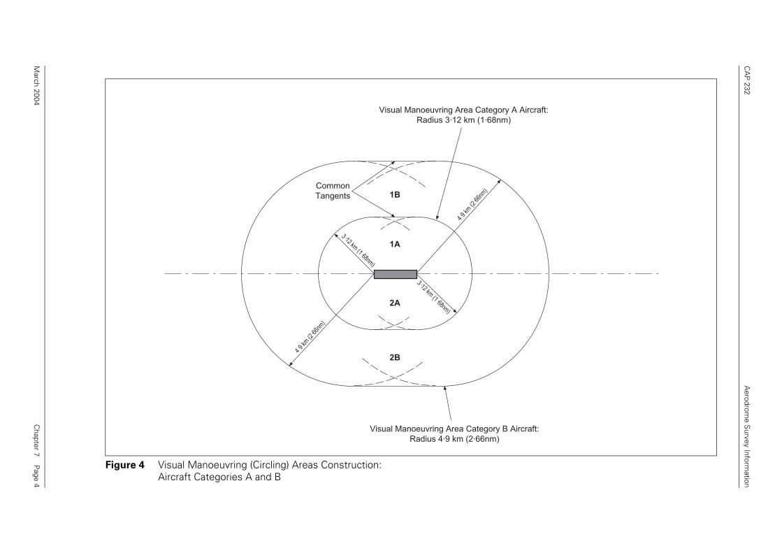
2.2.3 The survey areas for consideration are constructed by describing arcs of theappropriate radius as detailed below, centred on the thresholds, and joined bycommon tangents to form an enclosed area (see Figure 4).
2.2.4 The Aerodrome Licensee shall advise on circling Category requirements.
2.2.5 The survey requirement is to height the three highest obstacles in each segmentdefined by the extended runway centre lines and aircraft category boundaries (seeFigures 4 and 5), thus allowing the IFP designer to calculate the most advantageousminimum OCA/H.
2.3 Departure Areas
2.3.1 Applicable to runways from which IFR departures take place.
2.3.2 The Departure survey area is illustrated in Figure 6. NOTE: Area 2 may vary accordingto Departure Procedure Design requirements.
2.3.3 The survey requirement is to height all obstacles in this area that penetrates the 1:40slope.
3 Digital Data
All surveyed obstacles shall form part of the "Master Obstacles listing" shown inAnnex B
• Category A aircraft: 3.12 Kilometres (1.68 Nautical Miles)
• Category B aircraft: 4.90 Kilometres (2.66 Nautical Miles)
• Category C aircraft: 7.85 Kilometres (4.20 Nautical Miles)
• Category D aircraft: 9.79 Kilometres (5.28 Nautical Miles)
• Category E aircraft: 12.82 Kilometres (6.94 Nautical Miles)
Chapter 7 Page 2March 2004

CA
P 232
Aerodrom
e Survey Inform
ation
Chapter 7 P
age 3
10 km
10 km
March 2004
Figure 3 Non - Precision Instrument Approach Area
Minimum tile size in thissegment 0·5 x 1 kmEach tile is 0·5 x 1 km
10 km
10 km
5km
5km
5km
RunwayRunwayRunway
CA
P 232
Aerodrom
e Survey Inform
ation
Chapter 7 P
age 4
ory A Aircraft:nm)
y B Aircraft:)
March 2004
Figure 4 Visual Manoeuvring (Circling) Areas Construction: Aircraft Categories A and B
Visual Manoeuvring Area CategRadius 3·12 km (1·68
Visual Manoeuvring Area CategorRadius 4·9 km (2·66nm
CommonTangents
4·9
km (2
·66n
m)
4·9
km (2
·66n
m)
3·12 km (1·68nm
)
3·12 km (1·68nm
)
1B
1A
2A
2B

CA
P 232
Aerodrom
e Survey Inform
ation
Chapter 7 P
age 5
uvring AreaB Aircraft
15-33 Extended R/W CL
2C
09-27 Extended R/W CL
March 2004
Figure 5 Example - Visual Manoeuvring (Circling) Areas
Visual Manoeuvring AreaCategory C Aircraft Visual Manoe
Category
Visual Manoeuvring AreaCategory A Aircraft
Example of a two runwayconfiguration servicingaircraft category A to C
15-33 Extended R/W CL
1C
3A
3B
3C
4A
4B
4C
09-27 Extended R/W CL
2A
2B
15
33
09 27
1B
1A
1B
1A

CA
P 232
Aerodrom
e Survey Inform
ation
Chapter 7 P
age 6
5262m
Area 2
igher.
236·5m
March 2004
Figure 6 Departure Area 1 and 2NOTE: Area 2 may vary according to Departure Procedure Design requirements
9260m
3500m
15º
15º 1088m
Area 1
Origin of 1:40 surface at 5mabove departure end of runwayor end of clearway whicheveris higher.
NOTE: 1. Origin of 1:40 surface starts at Departure End of Runway (DER). 2. DER = end of runway or clearway as appropriate. 3. Elevation of DER = elevation of end of runway or elevation of end of clearway, whichever is h
1:40
5m
150m
150m
1:40

CAP 232 Aerodrome Survey Information
Chapter 8 Aerodrome Obstacle Chart - ICAO Type A
Survey Area
1 Purpose
1.1 The Type A chart provides data necessary to enable the aircraft operator to complywith the operating limitations of ICAO Annex 6 - Operation of Aircraft.
1.2 Aerodrome Obstacle Charts - ICAO Type A (Operating Limitations) shall be madeavailable (as prescribed in ICAO Annex 4 Aeronautical Charts) for all runways used byPerformance Group A aeroplanes engaged in Public Transport flights. Runways thatdo not have obstacles in the take-off flight path (TOFP) areas shall be recorded as notrequiring a Type A chart.
1.3 The CAA will undertake the preparation of the Type A chart from the informationsupplied by the surveyor. The CAA will determine which obstacles are to be shownon the final Type A chart by the application of complex shadowing techniques.
2 Survey Specification
2.1 Aerodrome Area
2.1.1 The elevation AMSL, at the start and end of TORA, end of ASDA and end of TODA,and at regular intervals (maximum 200 metres) along the runway and clearwaycentreline shall be provided.
2.1.2 The type of clearway and declared distances for TORA, TODA, ASDA and LDA shallbe stated in the Survey Report. If these have not already been agreed with ASD SRGthey must be submitted for verification before the Survey is started. Definitions arestated in CAP 168.
2.2 Take-Off Flight Path (TOFP) Area
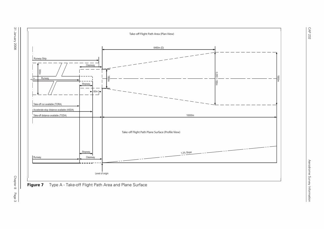
2.2.1 The area to be surveyed originates at the end of the TODA. It is 180m wide at origin,symmetrical about the extended centreline and increases uniformly at a rate of 0.25Dto a maximum width of 1800m, where D is the distance from origin. At a distance of6480m it extends at the maximum width to a distance of 10000m. The elevation ofthe origin is the elevation declared for the end of TODA (see Figure 7).
2.2.2 The flight path plane surface has an upward slope of 1.2% from the origin (see Figure7).
2.2.3 All objects and terrain within the TOFP area shall be comprehensively analysed. Allobstacles that penetrate the TOFP surface shall be surveyed except where suchobstacles are in the shadow of others. The shadow of an obstacle is considered to bea plane surface originating at a horizontal line passing through the top of the obstacleat right angles to the centreline of the TOFP, and extended to cover the completewidth of the area. Frangible and mobile obstacles shall not shadow other obstacles.If the obstacle creating a shadow is likely to be removed, objects that would becomedominant by its removal shall be surveyed. If the surveyor is unclear as to whichobstacles are dominant then all obstacles penetrating the surface shall be surveyed.
2.2.4 For runways serving aircraft having operational limitations that do not preclude theuse of a gradient less than 1.2%, the TOFP area is increased to 12000m and the slope
Chapter 8 Page 131 January 2008

CAP 232 Aerodrome Survey Information
of the plane surface is reduced to 1% or less. Where the plane of the 1% slope doesnot touch any objects, it is to be reduced until it touches the first object.
2.2.5 The elevation AMSL of any road, railway track or water feature capable of supportingmobile obstacles greater than 4.8m (for waterways the high and low water marks andthe height of shipping) shall be surveyed at a regular interval to its full linear extent,until shadowed by the next dominant obstacle if the combined elevation penetratesthe TOFP surface. The combined elevation shall be provided.
2.2.6 Where the TOFP is at an offset angle from the runway extended centreline in orderto gain an operational advantage, the area to be surveyed shall be determined byconsultation between the Aerodrome Licensee and aircraft operators concerned, andagreed with SRG, CAA and annotated in the survey report.
3 Digital Data
All surveyed obstacles shall form part of the “Master Obstacles listing” depicted inAnnex B. Positional data, and associated elevations, that determines the extent of thedeclared distances and runway profile shall be included in the ‘Aerodrome Facilitieslisting’ depicted in Annex B.
Chapter 8 Page 231 January 2008
CA
P 232
Aerodrom
e Survey Inform
ation
Chapter 8 P
age 3
0.25D + 180m
1800m
31 January 2008
Figure 7 Type A - Take-off Flight Path Area and Plane Surface
300m
Stopway
Runway
Take-off Flight Path Area (Plan View)
Take-off Flight Path Plane Surface (Profile View)
6480m (D)
60m
Stopway
Clearway
Clearway
Take-off run available (TORA)
Runway Strip
Accelerate-stop distance available (ASDA)
Take-off distance available (TODA) 10000m
1.2% Slope
Level of origin
Runway
180m

INTENTIONALLY LEFT BLANK

CAP 232 Aerodrome Survey Information
Chapter 9 Precision Approach Procedure Survey Area
1 Purpose
1.1 The survey is to identify obstacles within the Precision Approach area. It providesimportant data for the safety assessment of Precision Approach procedures and thecalculation of obstacle clearance heights.
1.2 The survey provides data for use in connection with the following precision approachprocedures:
• ILS (including Offset Localiser facilities)
• MLS (including Offset Azimuth facilities)
(NOTE: ILS Localiser only and MLS Azimuth only are non-precision approachprocedures and survey requirements are detailed in Chapter 7.)
1.3 In the case of offset facilities (where the localiser is not aligned with the extendedrunway centreline), TA, DAP, CAA House should be consulted on the alignment of thesurvey area required.
2 Survey Specification
2.1 The ILS Basic Surfaces area is illustrated in Figure 8.
2.2 The survey requirement is to height all obstacles in this area that penetrate thesurfaces.
3 Digital Data
All surveyed obstacles shall form part of the “Master Obstacles listing” depicted inAnnex B.
Chapter 9 Page 1March 2004

CA
P 232
Aerodrom
e Survey Inform
ation
Chapter 9 P
age 2
·5%)
1:40
1:40
3015m
pproach
March 2004
Figure 8 Basic ILS Surfaces
2040m
2280m2250m
900m
Approach
Datum - Landing Threshold Elevation
60m
15%
15%
17·48%
17·48%
25%
25%
1:40 (2·5%)
1:50 (2·0%)
1:40 (2
Plan - Obstacle areas for consideration
1:50
1:50
1:40
1:40
TRANSITIONAL SURFACE 1:7
TRANSITIONAL SURFACE 1:7
12900m12660m
Landing Threshold
300m Above
Landing threshold
Elevation
Initial
Missed
Approach
Missed A
150m
150m
Profile - Showing obstacle surfaces
3060m 2700m
CAP 232 Aerodrome Survey Information
Chapter 10 Precision Approach Terrain Chart Survey Area
1 Purpose
1.1 The Precision Approach Terrain Chart (PATC) provides a detailed terrain profile of thefinal portion of a Precision Approach. It provides information to enable the evaluationof the effects of the terrain on decision height determination using radio altimeters.
1.2 It is a mandatory requirement for aerodromes that conduct Cat II, III precisionapproaches to provide data to the CAA to enable the preparation and publication ofthe PATC.
2 Survey Specification
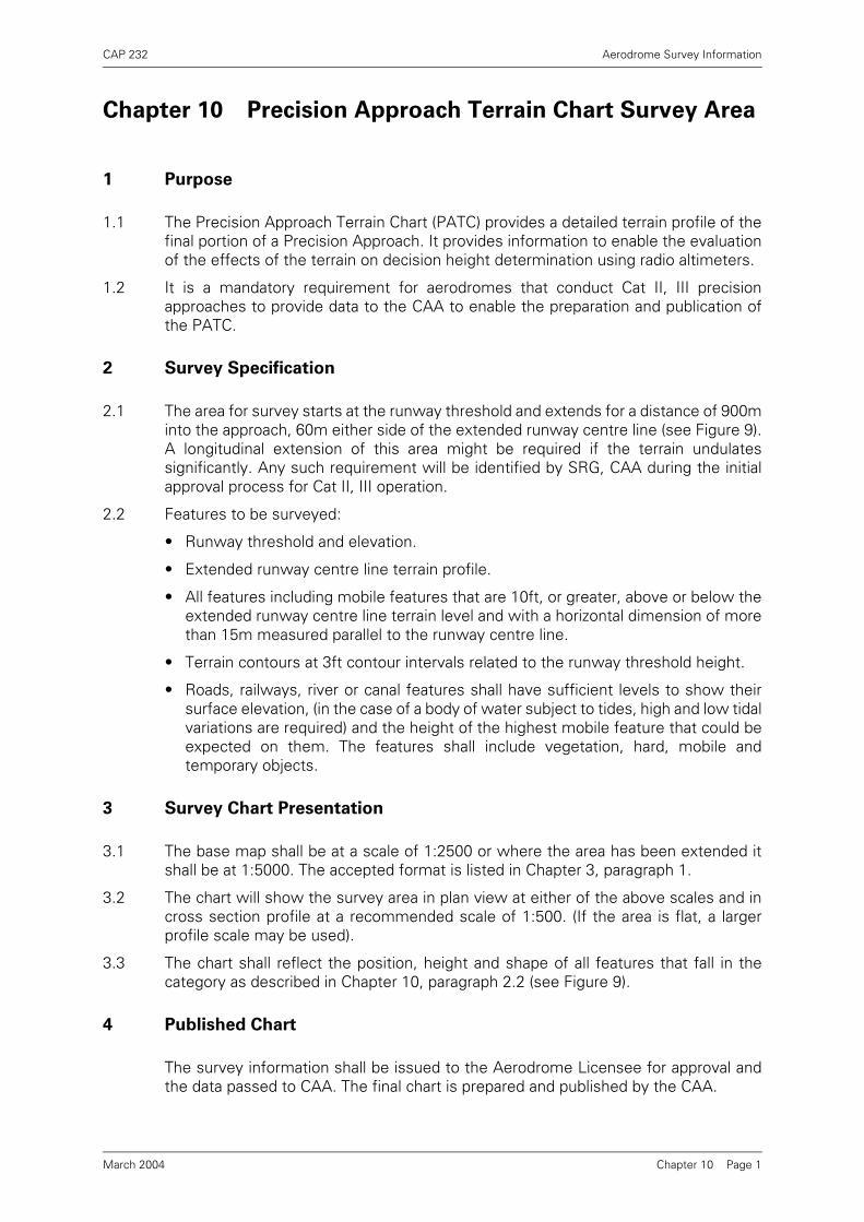
2.1 The area for survey starts at the runway threshold and extends for a distance of 900minto the approach, 60m either side of the extended runway centre line (see Figure 9).A longitudinal extension of this area might be required if the terrain undulatessignificantly. Any such requirement will be identified by SRG, CAA during the initialapproval process for Cat II, III operation.
2.2 Features to be surveyed:
• Runway threshold and elevation.
• Extended runway centre line terrain profile.
• All features including mobile features that are 10ft, or greater, above or below theextended runway centre line terrain level and with a horizontal dimension of morethan 15m measured parallel to the runway centre line.
• Terrain contours at 3ft contour intervals related to the runway threshold height.
• Roads, railways, river or canal features shall have sufficient levels to show theirsurface elevation, (in the case of a body of water subject to tides, high and low tidalvariations are required) and the height of the highest mobile feature that could beexpected on them. The features shall include vegetation, hard, mobile andtemporary objects.
3 Survey Chart Presentation
3.1 The base map shall be at a scale of 1:2500 or where the area has been extended itshall be at 1:5000. The accepted format is listed in Chapter 3, paragraph 1.
3.2 The chart will show the survey area in plan view at either of the above scales and incross section profile at a recommended scale of 1:500. (If the area is flat, a largerprofile scale may be used).
3.3 The chart shall reflect the position, height and shape of all features that fall in thecategory as described in Chapter 10, paragraph 2.2 (see Figure 9).
4 Published Chart
The survey information shall be issued to the Aerodrome Licensee for approval andthe data passed to CAA. The final chart is prepared and published by the CAA.
Chapter 10 Page 1March 2004
CAP 232 Aerodrome Survey Information
5 Chart Maintenance
5.1 It is the responsibility of the Aerodrome Licensee to monitor any changes in theapproach terrain profile. If significant changes occur the Aerodrome Licensee shallnotify them by NOTAM and provide appropriate new survey data to the CAAimmediately.
5.2 All changes in the profile that exceed the following limits shall be recorded:
• Changes in slope of 12.5% or more over a distance of 15m or more.
• Changes in the contour height of 10ft or more (increase or decrease) and over 15mto the defined approach area.
• All features as stated in paragraph 2.2.
NOTE: It is important that both increases and decreases in elevation are significant.
Chapter 10 Page 2March 2004

CA
P 232
Aerodrom
e Survey Inform
ation
Chapter 10 P
age 3
120m
19·1881·0
19·5
19·219·1
19·1
CO
PS
E -
YO
UN
G T
RE
ES
DE
CID
UO
US
792·0
851·0881·0
900·0
March 2004
Figure 9 Precision Approach Terrain Chart
900m
Horizontal Scale 1:2500Vertical Scale 1:500
2121
27
20.4
20·1
20·2
20·1
20·2
20·1
20.1
20·1
20·2
20·1
20·2
20·3
20·0
20·0
19·5
19·5
19·5
588·9
604·1
19·5
19·5
19·5
26
25
2322
212019
18
1716
15
24
20·20·0
20·2
-215·5
-159·5
-99.5
34·521 T
HR
ES
HO
LD B
AR
MO
BILE
OB
ST
RU
CT
ION
OB
ST
RU
CT
ION
MO
BILE
OB
ST
RU
CT
ION
BU
ILDIN
G
DE
LAP
IDA
TE
DD
ELA
PID
AT
ED
BU
ILDIN
G
DE
LAP
IDA
TE
D
81·6
118·5
137·6
176·5
192·5
276·5
309·1
292·1
355·0
400·0
490·0
588·9
604·1
651·0
0·0

INTENTIONALLY LEFT BLANK

CAP 232 Aerodrome Survey Information
Chapter 11 Page 1
Chapter 11 PAPI/APAPI Site Survey Area
Purpose
The survey is required to provide data to assist in the calculation for the siting of PAPI/APAPIunits on initial installation. Full details are contained in CAP 168. PAPI/APAPI surveys do notform part of the full and check survey procedures.
March 2004

INTENTIONALLY LEFT BLANK

CAP 232 Aerodrome Survey Information
Annex A Page 1
Annex A Survey Declaration Form
Aerodrome
Surveying Company
Aerodrome Classification Initial/Last Full Survey Date
Geodetic Connection Date* Annual Check Survey Date*
(* If applicable)
Survey Area RequiredNo Change to
Previous Survey
Change to Previous
Survey
Aerodrome Plan
AGA
Non-Precision Instrument Approach
Visual Manoeuvring (Circling)
Departure
Aerodrome Obstacle Chart - Type A
Precision Approach Procedure
Precision Approach Terrain Chart
(Check box as appropriate)
Declaration by Aerodrome Licensee’s Representative
I certify that information supplied meets the Aerodrome’s operational requirements
Name
Position
Signature Date
Declaration by Surveyor
I certify that information supplied is complete and conforms to CAP 232 (Edition 3)
Name
Signature Date
Submit form together with all relevant survey information to:ACD, DAP, CAA House, 45-59 Kingsway, London WC2B 6TE
March 2004

INTENTIONALLY LEFT BLANK

CAP 232 Aerodrome Survey Information
Annex B Digital Data Specification
Master files of all surveyed facilities and obstacles shall be created and supplied.
Files of survey information shall be in the form of a comma delimited ASCII text file containingfourteen fields plus CRC field as listed below.
Aerodrome facilities file (named appropriately e.g. egxx_ad00.crc)
To be entered in field Description
Field 1 SITE NAME
EGXX ICAO Aerodrome Location Indicator
Field 2 TYPE OF FEATURE
ABN Aerodrome Beacon
ATC Air Traffic Control Location
ASDA_END End of ASDA
CHECK_PT1 Additional point along runway
CHECK_PT2 Additional point along runway
DME Distance Measuring Equipment
FATO Final Approach and Take-off Area
GP Instrument Landing System Glidepath
IBN Identification Beacon
IRVR Instrument Runway Visual Range
L Locator (NDB)
LDA_END End of LDA
LLZ Instrument Landing System Localizer
MLS_AZM Microwave Landing System Azimuth
MLS_ELEV Microwave Landing System Elevation
MM Middle Marker
NDB Non-directional Radio Beacon
OM Outer Marker
RADAR RADAR
ROP Runway Observing Position
STAND Stand
THR Runway Threshold
Annex B Page 131 January 2008

CAP 232 Aerodrome Survey Information
TLOF Touchdown and Lift-off Area
TODA_END End of TODA
TORA_START Start of TORA
TORA_END End of TORA
VDF Very High Frequency Direction-finding Station
VOR VHF Omnidirectional Radio Range
VOR/DME VOR co-located with DME
Field 3 IDENTIFICATION
ABC Call sign of navigation aid
05L Runway threshold, LLZ and GP designator
05/23 Runway and DME designator
123 Stand number
Field 4 LATITUDE
522704.83N WGS-84 Latitude in DEG, MIN, SEC, 1/100’s SEC
Field 5 LONGITUDE
0014431.27W WGS-84 Longitude in DEG, MIN, SEC, 1/100’s SEC
Field 6 ELLIPSOIDAL HEIGHT (M)
107.00 Elevation in metres above WGS-84 ellipsoid to 2 decimal places
Field 7 ELLIPSOIDAL HEIGHT (FT)
351.05 Elevation in feet above WGS-84 ellipsoid to 2 decimal places
Field 8 LIT OR UNLIT
Y To be entered if facility is lit
N To be entered if facility is unlit
Field 9 EASTING
312567.75 Six figure easting grid reference to 2 decimal places
Field 10 NORTHING
435687.55 Six figure northing grid reference to 2 decimal places
Field 11 ORTHOMETRIC HEIGHT (M)
113.76 Elevation in metres AMSL to 2 decimal places
Field 12 ORTHOMETRIC HEIGHT (FT)
373.22 Elevation in feet AMSL to 2 decimal places
Annex B Page 231 January 2008

CAP 232 Aerodrome Survey Information
Example of CRC wrapped records in file:EGXX,NDB,ABC,522732.45N,0014429.34W,119.74,393,Y,417662.27,284592.54,70.35,231,1008,10/01/00,45F652A2
EGXX,LLZ,05L,522758.83N,0014539.27W,117.96,387,N,416246.56,285408.34,103.63,340,1010,10/01/00,E74FA6A3
EGXX,STAND,5,522701.13N,0014399.21W,115.82,380,N,418234.34,283673.22,101.5,333,1013,12/01/00,219C3FE9
Master obstacles file (named appropriately e.g. egxx_obst00.crc)
Field 13 RECORD IDENTIFIER
1056 Unique integer number
Field 14 SURVEY DATE
10/01/00 Date of field survey of record (dd/mm/yy format)
Field 15 CRC Value 32 bit CRC-32Q algorithm Value (CRCV format = Hexadecimal)
AB47A43 (Created by Eurocontrol CRC tool)
To be entered in field Description
Field 1 SITE NAME
EGXX ICAO Aerodrome Location Indicator
Field 2 TYPE OF FEATURE
OBST Obstacle
Field 3 IDENTIFICATION
BUILDING Description of obstacle
Field 4 LATITUDE
522704.83N WGS-84 Latitude in DEG, MIN, SEC, 1/100’s SEC
Field 5 LONGITUDE
0014431.27W WGS-84 Longitude in DEG, MIN, SEC, 1/100’s SEC
Field 6 ELLIPSOIDAL HEIGHT (M)
107.00 Elevation in metres above WGS-84 ellipsoid to 2 decimal places
Field 7 ELLIPSOIDAL HEIGHT (FT)
351.05 Elevation in feet above WGS-84 ellipsoid to 2 decimal places
Field 8 LIT OR UNLIT
Y To be entered if obstacle is lit
N To be entered if obstacle is unlit
Field 9 EASTING
312567.75 Six figure easting grid reference to 2 decimal places
Annex B Page 331 January 2008
CAP 232 Aerodrome Survey Information
Example of CRC wrapped records in file:EGXX,OBST,TREE,533211.60N,0002217.25W,322,136.24,447,N,376673.45,404383.54,98.15,322,1001,10/01/00,AB47A43
EGXX,OBST,CHURCH_SPIRE,533659.04N,0002001.07W,121.31,398,Y,399978.89,413280.67,74.98,246,1002,10/01/00,86789C79
EGXX,OBST,MAST,532725.46N,0001918.10W,222.20,729,Y,511435.56,396978.78,175.87,577,1003,10/01/00,5A6B1656
EGXX,OBST,RADAR,532619.85N,0001818.85W,249.63,819,Y,512713.38,394913.55,203.30,667,1005,10/01/00,EB6EB575
EGXX,OBST,PYLON,533029.93N,0001819.19W,223.42,733,N,512407.45,402640.98,177.09,581,1008,10/01/00,230E3C1D
Special Notes:
• Decimal places shall not be rounded.
• Only decimal places, underscores and forward slashes shall be used within fields(no hyphens, word spaces, commas or backslashes, etc.).
• All text shall be upper case.
• All fields shall be populated with the exception of the aerodrome facilities file Field3, which must be blank if there is no associated identification (Duplicate data in arecord is not acceptable).
Field 10 NORTHING
435687.55 Six figure northing grid reference to 2 decimal places
Field 11 ORTHOMETRIC HEIGHT (M)
113.76 Elevation in metres AMSL to 2 decimal places
Field 12 ORTHOMETRIC HEIGHT (FT)
373.22 Elevation in feet AMSL to 2 decimal places
Field 13 RECORD IDENTIFIER
1056 Unique integer number
Field 14 SURVEY DATE
10/01/00 Date of field survey of record (dd/mm/yy format)
Field 15 CRC Value
AB47A43 32 bit CRC-32Q algorithm Value (CRCV format = Hexadecimal)(Created by Eurocontrol CRC tool)
Annex B Page 431 January 2008

CAP 232 Aerodrome Survey Information
Annex C Methodology of Modelling Obstacles (For
information only)
1 Introduction
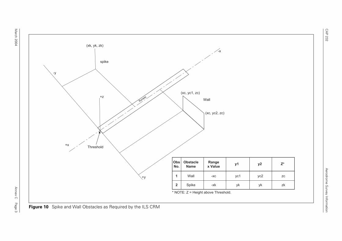
The ILS Collision Risk Model (CRM) requires position and dimension data for allrelevant obstacles. The data can be entered in the co-ordinate system (x,y,z) orconverted from other co-ordinate systems to the (x,y,z) system.
2 Description of Artificial Obstacles
For processing by the CRM, obstacles must be of a specific form: either as a spike ora wall as shown below (see Figure10). For the purposes of the CRM, therefore,obstacles after adjustment (see paragraph 5) have height and width but do not havelength.
3 Simple Obstacle Modelling
Obstacles are usually of a complex shape, unlikely to be orientated at right angles tothe line of approach, and may well extend longitudinally for considerable distance.These can be expressed as a number of simple obstacles as spikes or a series of walls(see Figures 11 and 12).
In general obstacle modelling should be as simple as possible with conservativedimensions assigned.
4 Sophisticated Obstacle Modelling
4.1 If analysis of the CRM results shows that the precise shape of an obstacle is criticalwith respect to the total risk, a more sophisticated obstacle model may be requiredas detailed below:
• Construct lines parallel to the x axis through y1 and y2, the outer edges of theobstacle in the y axis. The perpendicular distances from these lines to the x axisare the lateral boundary dimensions.
• The height (z) of the obstacle is taken to be that of the highest point abovethreshold elevation.
• The range (x) is the perpendicular distance from the obstacle boundary pointnearest to the threshold.
4.2 If a solid obstacle is modelled by spike obstacles, lateral spacing should be not morethan the wing span of the largest aircraft likely to use the airport.
4.3 If the difference between the most distant point and the nearest point of the obstacleto the threshold exceeds 100m, the obstacle should be partitioned into a series ofwall obstacles separated by no more than 100m in range. The height assigned to sucha “wall” obstacle should be the highest elevation of the obstacle in the area awayfrom the runway. In cases where the obstacle height varies with distance from thecentre line, each wall may be broken up into two or more adjacent walls.
Annex C Page 1March 2004

CAP 232 Aerodrome Survey Information
5 Considerations on Accuracy
Consideration should be given to the accuracy with which the obstacle data has beencollected. Suitable adjustments should be made to take account of inaccuracies in theobstacle data; these should result in a greater height, a smaller (absolute) range, anda smaller (absolute) lateral displacement. If these adjustments lead to unacceptableoperational penalties, more accurate surveying may reduce these penalties. Inaddition adjustments for such things as tree growth may be taken into account byadding a tolerance to the height.
Annex C Page 2March 2004
CA
P 232
Aerodrom
e Survey Inform
ation
Annex C
Page 3
, zc)
-x
reshold.
e
ey1 y2 Z*
yc1 yc2 zc
yk yk zk
March 2004
Figure 10 Spike and Wall Obstacles as Required by the ILS CRM
+x
+z
(xk, yk, zk)
(xc, yc1, zc)
(xc, yc2
Runway
-y
+y
spike
Threshold
* NOTE: Z = Height above Th
Wall
Obs
No.
Obstacle
Name
Rang
x Valu
1 Wall -xc
2 Spike -xk

CA
P 232
Aerodrom
e Survey Inform
ation
Annex C
Page 4
-x
stacle
amex y1 y2 z
nt Apex -xa -y1 -y1 za
t Corner -xa -y2 -y2 zb
le Apex -xb -y1 -y1 za
le Corner -xb -y2 -y2 zb
k Apex -xc -y1 -y1 za
k Corner -xc -y2 -y2 zb
March 2004
Figure 11 Example of Obstacle Modelling
-y
+y+x
1
2
3
4
5
6
Obs
No.
Ob
N
1 Fro
-xa
-y1
2 Fron
-y2
3 Midd
-xb
4 Midd
5 Bac
6 Bac
-xc
Threshold

CA
P 232
Aerodrom
e Survey Inform
ation
Annex C
Page 5
-y
Alt or
Heighty1 y2
H'y'1 y'2
H-y1 -y2
= Z
March 2004
Figure 12 Examples of Irregular Shaped Obstacles
Threshold+y
y1
y2
y'2
y'1
x'
x
+x
-x
Obs
No.
Obstacle
Name
Range
x Value
1 Building x'
2 Hill x
1
2

CA
P 232
Aerodrom
e Survey Inform
ation
Annex C
Page 6
Building B
reshold
-y
x
B1
B2
B3
B4
B1
B2
B3
B4
-y1 -y2
y2 z
-y2 z2
-y2 z2
-y2 z2
-y2 z2
March 2004
Figure 13 Partitioning of Continuous Obstacles (Buildings)
Building A
Th
A3
+y
+
A2
A1
Obs
No.
Obstacle
Namex y1 y2 z
A1 Building A x1
x3
y1 y2 z1
A2 Building A x2
x2
y3
y3
y4
y4
z1
A3 Building A x3
x1
y5
y5
y6
y6
z1x6
x5
x4
y2y1
Obs
No.
Obstacle
Namex y1
B1 Building B x6 -y1
B2 Building B x5 -y1
B3
B4
Building B
Building B
x4 -y1
x1 -y1
A2
A1

CA
P 232
Aerodrom
e Survey Inform
ation
Annex C
Page 7
Range
x Value
Obstacle
Height*y1 y2
380280280280180180180
808080606060
-20140
-105-80
-119-247-60-85
-245-60-85
-240-62
-100-260
-70-130
-250-119-247-274-85
-245-275
-85-240-273-100-260
-2271-268-130
H2 + TgH2 + TgH3 + TgH2 + TgH2 + TgH3 + TgH2 + TgH2 + TgH3 + TgH2 + TgH2 + TgH3 + TgH2 + TgH2 + Tg
H4
eshold.tree height or growth..
= Z
March 2004
Figure 14 Partitioning of a Continuous Obstacle (Hill)
Obs
No.
Obstacle
Name
Threshold
+y -y
+x
y=-62
y=-100
y=-260
y=-260
y=-260
y=-271
y=-2
73
y=-2
40
-268
-70
-20
15
H1
H3
H4
1
2
3
4
5
6
7
8
9
10
11
12
13
14
15
HillHillHillHillHillHillHillHillHillHillHillHillHillHill
Tower
* Z = Height above ThrTg is an allowance for All values are in metres
-250
-105
1
380-119
-80
H2
-60
-85280
2 3 4
-274
-247
5 6 7
-85
130
-275
-245
80
-60
180
8 9 10
140
11 12 13
60
14

CA
P 232
Aerodrom
e Survey Inform
ation
Annex C
Page 8
te System
y2
seconds E/W degrees minutes seconds
04·2102·1058·9558·9554·7402·10
07·3704·2102·1054·7453·1604·10
EEEEEE
444334
000000595900
in metres.
-y
March 2004
Figure 15 Method of Partitioning a Continuous Obstacle (Railway)
Obs
No.
Obstacle
Name
Runway
Co-ordinate System
Geographical Co-ordinaObstacle
Height* (m)
above Thldx(m) y1(m) y2(m)
1
2
3
4
5
6
RailwayRailwayRailwayRailwayRailwayTower
127125121125120155
8040
-20-20
-10040
1408040
-100-130
40
528552055165511550605215
N/S degrees minutes
x y1
seconds E/W degrees minutes
08·7811·3712·6714·2916·0711·05
EEEEEE
NNNNNN
515151515151
575757575757
443334
000059595900
* If the obstacle is a road or railway interval, use the maximum height in the interval of the road or railway.
Threshold
Note: All values are
+y
+x
5
6
52 N
4 E
N
5115
-80
140
1
4
-1005285
-20
5205
5060
5165
2
-40
3
-130