Embed Size (px)
Citation preview
Can’t We All Just Get Along? Advanced Workflows Between Autodesk® Revit® and Autodesk® AutoCAD® Civil 3D®
Brian Levendowski, PE – CAD Technology Center, Inc.
Shawn Zirbes – CAD Technology Center, Inc.
CI3206 – “Now, now, children, let’s all play nice together.” Remind you of your childhood?
Yeah, mine too. But what we’re talking about is architects and civil engineers playing together,
specifically when it comes to coordinating Autodesk Revit and Autodesk AutoCAD Civil 3D data
on the same project. This class is directed at both Revit and Civil 3D software users. That’s
right, architects and civil engineers in the same room. We work in both Revit and Civil 3D,
showing you proper importing and exporting of data, so it lands in the correct place
automatically. We teach you how to ask for the correct data, as well as a good understanding of
one another’s software. We cover how to create good topo in Revit, and how that compares to
topos in Civil 3D. The tools for smooth collaboration exist in both Revit and Civil 3D, and there’s
just a communication breakdown preventing truly streamlined BIM workflow between the 2
disciplines. So join us and take your projects to the next level.
Learning Objectives
At the end of this class, you will be able to:
Explain what data types civil engineers are creating in Civil 3D and architects are creating in Revit
Incorporate site topographies and designs created in Civil 3D into Revit and properly align them to your design
Properly export Revit models in preferred formats for use by civil engineers in Civil 3D
Import building designs into Civil 3D and export the correct data for use by the building designer in Revit
Can’t We All Just Get Along? Advanced Workflows Between Autodesk® Revit® and Autodesk® AutoCAD® Civil 3D®
2
About the Speakers
Brian Levendowski, PE currently works as an Application Engineer for CAD Technology
Center, an Autodesk Gold Partner in Minnesota. He is a highly-rated Autodesk University
Speaker and has extensive experience working with the infrastructure industry, providing all
levels of training, consultation and support. He is currently leading several advanced
implementations of BIM software, including Civil 3D, for firms, both large and small. With a
practical background as a Civil Engineer, Inspector, and Land Surveyor, he has valuable real-
world experience, and truly understands the application of Autodesk software in the
infrastructure industry.
Shawn Zirbes is the Chief Technical Officer for CAD Technology Center, Inc., in Minnesota.
With thirteen years experience using all Autodesk® AEC software, he is an expert in planning
and executing software implementations for the AEC industry. He has worked with a wide
variety of clients ranging from commercial, residential, health care, and industrial design firms,
their consultants, and the building product manufacturers supplying the building materials for
these projects. Shawn's wide range of Building Information Modeling experience is being
leveraged by Autodesk as a special Revit® consultant for Autodesk Seek.
Can’t We All Just Get Along? Advanced Workflows Between Autodesk® Revit® and Autodesk® AutoCAD® Civil 3D®
3
REVIT WORKFLOWS
Importing Civil 3D Sites into Revit
1. Start a new Revit “Site” model
a. Do not generate site work in a live architectural model
i. EVER !!!
2. Access Civil plan view
a. Set view range to:
b. Cut plane @ 4000’
c. Top @ 4000’
3. Modify Levels
a. Rename Level 1 to “Sea Level”
b. Ensure Sea Level is at 0’- 0”
c. Rename Level 2 to Building X Main Level
d. Set Building X Main Level to approximate building elevation (IE: 800’- 0”)
4. Link Civil drawing using
a. Insert Link CAD
b. Use the following settings
i. Positioning : Auto – Origin to Origin
ii. DO NOT Check “Correct lines that are slightly off axis”
iii. Place at : Sea Level
Generating Terrain Models in Revit
1. Ensure that a CAD link exists in the Site plan view
2. Use Massing & Site Toposurface
a. Use Modify|Edit Surface Create from Import Select Import Instance
i. Select the Cad link
ii. Select Layers that should be used for site generation
1. Do not just use all layers
b. View from 3D terrain in 3D to ensure that what you generated is not bogus
c. Finish editing the surface
3. Do other site stuff to the site
a. Generate Subregions to develop material articulation
Establishing Shared Coordinates in Site Model – Method 1
1. In Site plan view locate the ‘Reference Point(s)’ from Civil drawing
a. Record the values on a sheet of paper
2. Access ‘Visibility/Graphic Overrides for Floor Plan: Site’
a. On Model Tab find the Site category
i. Under Site category
Can’t We All Just Get Along? Advanced Workflows Between Autodesk® Revit® and Autodesk® AutoCAD® Civil 3D®
4
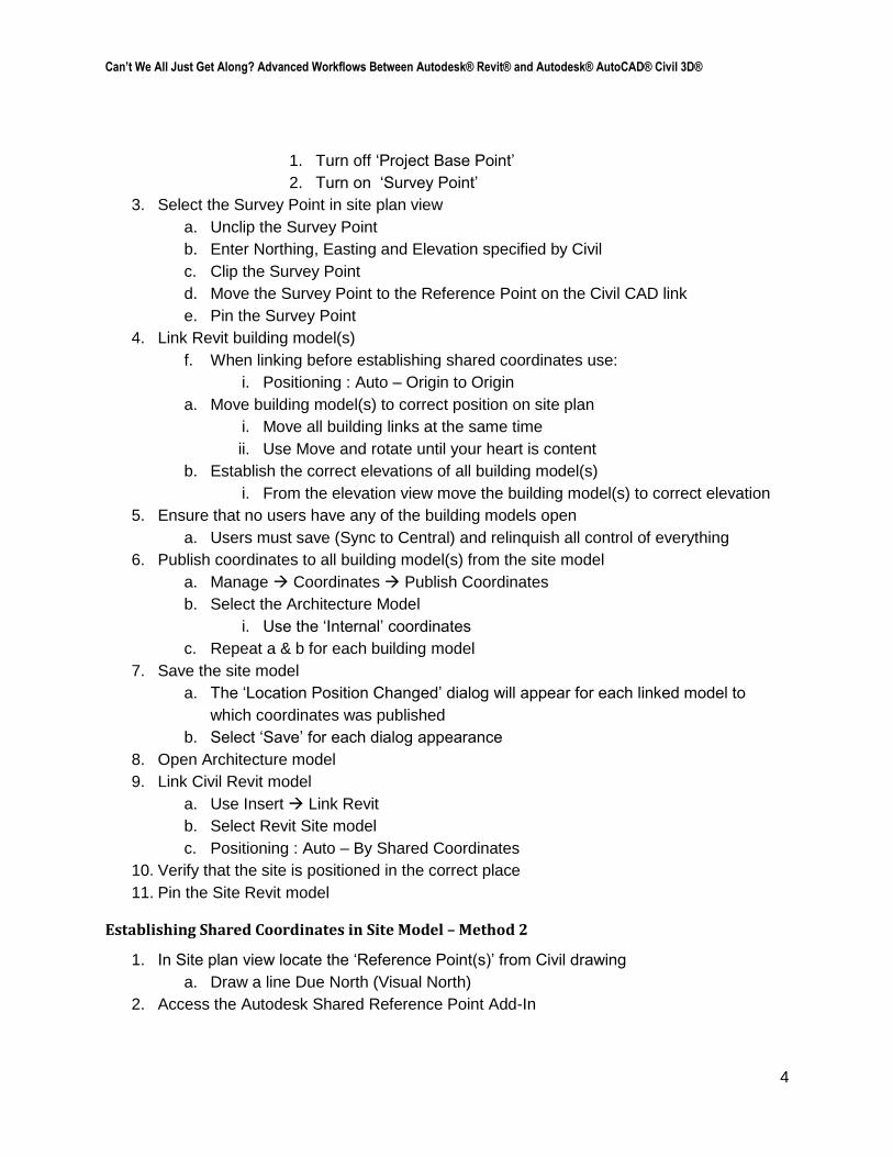
1. Turn off ‘Project Base Point’
2. Turn on ‘Survey Point’
3. Select the Survey Point in site plan view
a. Unclip the Survey Point
b. Enter Northing, Easting and Elevation specified by Civil
c. Clip the Survey Point
d. Move the Survey Point to the Reference Point on the Civil CAD link
e. Pin the Survey Point
4. Link Revit building model(s)
f. When linking before establishing shared coordinates use:
i. Positioning : Auto – Origin to Origin
a. Move building model(s) to correct position on site plan
i. Move all building links at the same time
ii. Use Move and rotate until your heart is content
b. Establish the correct elevations of all building model(s)
i. From the elevation view move the building model(s) to correct elevation
5. Ensure that no users have any of the building models open
a. Users must save (Sync to Central) and relinquish all control of everything
6. Publish coordinates to all building model(s) from the site model
a. Manage Coordinates Publish Coordinates
b. Select the Architecture Model
i. Use the ‘Internal’ coordinates
c. Repeat a & b for each building model
7. Save the site model
a. The ‘Location Position Changed’ dialog will appear for each linked model to
which coordinates was published
b. Select ‘Save’ for each dialog appearance
8. Open Architecture model
9. Link Civil Revit model
a. Use Insert Link Revit
b. Select Revit Site model
c. Positioning : Auto – By Shared Coordinates
10. Verify that the site is positioned in the correct place
11. Pin the Site Revit model
Establishing Shared Coordinates in Site Model – Method 2
1. In Site plan view locate the ‘Reference Point(s)’ from Civil drawing
a. Draw a line Due North (Visual North)
2. Access the Autodesk Shared Reference Point Add-In
Can’t We All Just Get Along? Advanced Workflows Between Autodesk® Revit® and Autodesk® AutoCAD® Civil 3D®
5
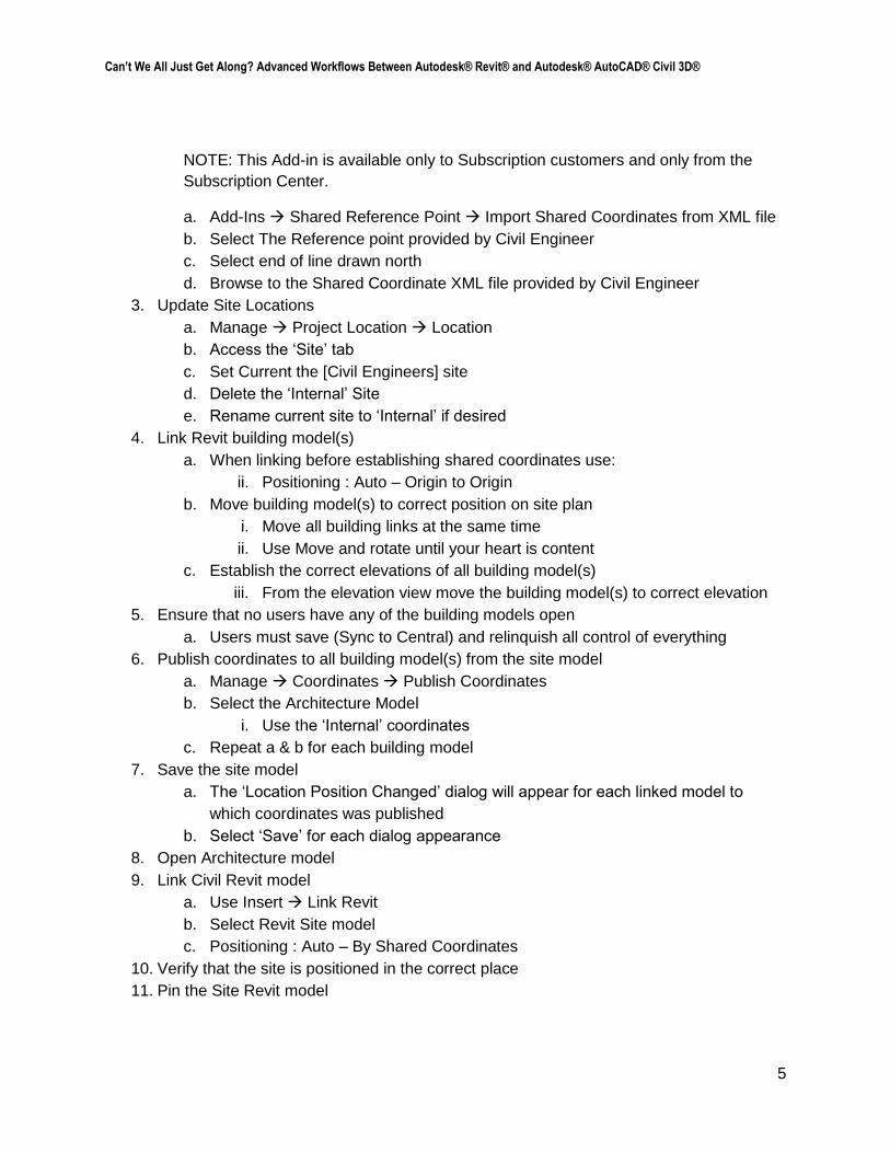
NOTE: This Add-in is available only to Subscription customers and only from the
Subscription Center.
a. Add-Ins Shared Reference Point Import Shared Coordinates from XML file
b. Select The Reference point provided by Civil Engineer
c. Select end of line drawn north
d. Browse to the Shared Coordinate XML file provided by Civil Engineer
3. Update Site Locations
a. Manage Project Location Location
b. Access the ‘Site’ tab
c. Set Current the [Civil Engineers] site
d. Delete the ‘Internal’ Site
e. Rename current site to ‘Internal’ if desired
4. Link Revit building model(s)
a. When linking before establishing shared coordinates use:
ii. Positioning : Auto – Origin to Origin
b. Move building model(s) to correct position on site plan
i. Move all building links at the same time
ii. Use Move and rotate until your heart is content
c. Establish the correct elevations of all building model(s)
iii. From the elevation view move the building model(s) to correct elevation
5. Ensure that no users have any of the building models open
a. Users must save (Sync to Central) and relinquish all control of everything
6. Publish coordinates to all building model(s) from the site model
a. Manage Coordinates Publish Coordinates
b. Select the Architecture Model
i. Use the ‘Internal’ coordinates
c. Repeat a & b for each building model
7. Save the site model
a. The ‘Location Position Changed’ dialog will appear for each linked model to
which coordinates was published
b. Select ‘Save’ for each dialog appearance
8. Open Architecture model
9. Link Civil Revit model
a. Use Insert Link Revit
b. Select Revit Site model
c. Positioning : Auto – By Shared Coordinates
10. Verify that the site is positioned in the correct place
11. Pin the Site Revit model
Can’t We All Just Get Along? Advanced Workflows Between Autodesk® Revit® and Autodesk® AutoCAD® Civil 3D®
6
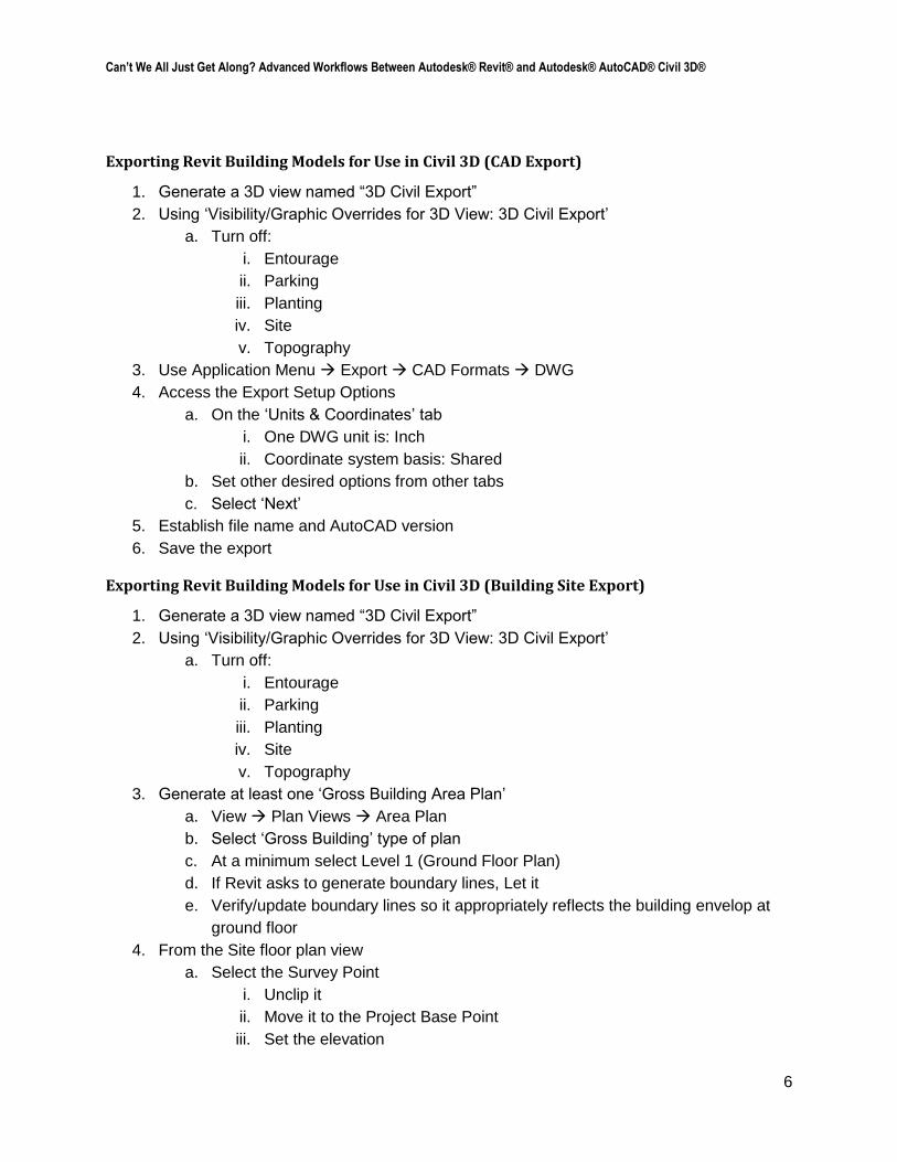
Exporting Revit Building Models for Use in Civil 3D (CAD Export)
1. Generate a 3D view named “3D Civil Export”
2. Using ‘Visibility/Graphic Overrides for 3D View: 3D Civil Export’
a. Turn off:
i. Entourage
ii. Parking
iii. Planting
iv. Site
v. Topography
3. Use Application Menu Export CAD Formats DWG
4. Access the Export Setup Options
a. On the ‘Units & Coordinates’ tab
i. One DWG unit is: Inch
ii. Coordinate system basis: Shared
b. Set other desired options from other tabs
c. Select ‘Next’
5. Establish file name and AutoCAD version
6. Save the export
Exporting Revit Building Models for Use in Civil 3D (Building Site Export)
1. Generate a 3D view named “3D Civil Export”
2. Using ‘Visibility/Graphic Overrides for 3D View: 3D Civil Export’
a. Turn off:
i. Entourage
ii. Parking
iii. Planting
iv. Site
v. Topography
3. Generate at least one ‘Gross Building Area Plan’
a. View Plan Views Area Plan
b. Select ‘Gross Building’ type of plan
c. At a minimum select Level 1 (Ground Floor Plan)
d. If Revit asks to generate boundary lines, Let it
e. Verify/update boundary lines so it appropriately reflects the building envelop at
ground floor
4. From the Site floor plan view
a. Select the Survey Point
i. Unclip it
ii. Move it to the Project Base Point
iii. Set the elevation
Can’t We All Just Get Along? Advanced Workflows Between Autodesk® Revit® and Autodesk® AutoCAD® Civil 3D®
7
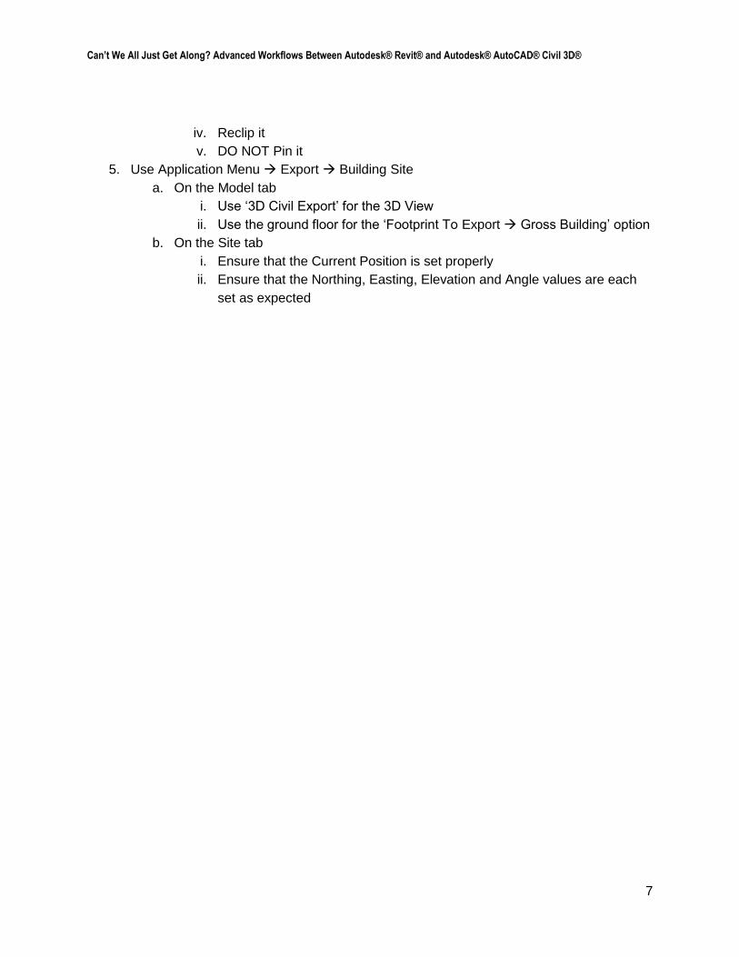
iv. Reclip it
v. DO NOT Pin it
5. Use Application Menu Export Building Site
a. On the Model tab
i. Use ‘3D Civil Export’ for the 3D View
ii. Use the ground floor for the ‘Footprint To Export Gross Building’ option
b. On the Site tab
i. Ensure that the Current Position is set properly
ii. Ensure that the Northing, Easting, Elevation and Angle values are each
set as expected
Can’t We All Just Get Along? Advanced Workflows Between Autodesk® Revit® and Autodesk® AutoCAD® Civil 3D®
8
CIVIL 3D WORKFLOWS
Exporting Civil 3D Sites for Use in Revit
It is important to understand that while Revit generates a topo surface through the connection of
designated points, it cannot incorporate other data types, nor apply “rules” in how the points get
connected (as Civil 3D does); no control lines, breaklines, or other feature elements. Revit
simply tries to connect the nearest points, whether they are actual points, or vertices of 3D lines
of any type. What this means for exporting Civil 3D surfaces, is that in areas where higher
detail is desired, additional points may be required for Revit to properly draw the desired surface
conditions. Common areas are near-vertical faces, such as curb lines or retaining walls. You
must create additional point data for Revit in all of these detailed areas so that Revit will build its
topo surface properly.
Below is an outline for Civil 3D users on how to properly provide Revit users with topo data that
will generate Revit Topos that fully mirror what was created in Civil 3D:
1. Extract 3D faces from Surface (creating combined EG/FG surface if necessary)
a. Have triangles on unique layer in Surface Style, so that during extraction, the
triangles will land on individual layer.
2. Create Cogo Points along all TIN edges that are significant grade changes, i.e., Curb,
retaining walls, etc., using the applicable method(s) below:
a. Survey figures and feature lines, and Grading Object Daylight line,
Alignments/Profiles
i. Point Creation tools Command Settings
1. Prompt for Elevations: Automatic
2. Prompt for Point Names: None
3. Prompt for Descriptions: Automatic
4. Next Point Number: 10000, or similar
ii. Create Points Miscellaneous: Measure Objects (Figures,
Feature/daylight lines)
iii. Create Points Alignment: Measure Alignment (Alignments/Profiles)
iv. Create enough points such that triangulation in Revit (based only on
points) will be in the correct direction. Some experimentation is often
required until you get the hang of it. For at 6” high curb for example,
creating points at 6” interval along the breakline will yield the desired
results in Revit.
b. Corridor
i. Increase frequency along TIN edges of significant grade change
ii. Select Corridor Contextual Ribbon Launch Pad Panel drop-down
Points from Corridor
Can’t We All Just Get Along? Advanced Workflows Between Autodesk® Revit® and Autodesk® AutoCAD® Civil 3D®
9
iii. Select Point Codes corresponding to applicable TIN edges. Common
examples for curb include Top_Curb, Flowline_Gutter.
3. Add new “Revit” points to new “Revit” surface.
a. Extract 3D faces from this Surface
4. Provide call-out of precise 3D location on site using a Cogo Point with Northing, Easting,
Elevation labeled
a. Explode Cogo Point to turn it into a block
5. WBLOCK 3D faces and label (nothing else) for use in Revit
6. If using Autodesk Shared Reference Point tool, run that command now.
a. When prompted for first point, pick 3D location mentioned above
b. Pick second point (or turn ortho on) in direction precisely north of 3D base point.
Distance is not important.
c. Confirm other default settings: origin, etc.
d. Save as XML file and send this to Revit user along with DWG
Importing Revit Building Models to Civil 3D
Civil Engineers need to design their sites around accurate representations of the building.
Below are two methods for incorporating building outlines from the Revit user in Civil 3D site
designs.
1. ADSK file
a. Insert Tab Import drop-down panel > Import Building Site
b. Browse to ADSK file. Name Building Site if desired.
c. Confirm Units and Style
d. Insertion point should be filled in if done properly in Revit. If 0,0,0, not done
correctly.
e. Building Site object has two view types available in Style
i. Model, which is the actual Revit model exterior
ii. Building Footprint, which is Gross Building Area in Revit
f. When Revit model changes, select Update Building Site Definition and browse to
updated file.
2. External Reference to AutoCAD drawing
a. Type “XR” Browse to DWG
b. Accept default insertion point
c. If doesn’t line up, export don incorrectly in Revit
3. ADSK vs. X’reffing AutoCAD drawing
a. ADSK is smaller, but less flexible in display
b. DWG is larger, but more flexible in display