Embed Size (px)
Citation preview
Important NoticeThis guide is delivered subject to the following conditions and restrictions:
This guide contains proprietary information belonging to Elmo Motion Control Ltd. Such information is supplied solely for the purpose of assisting users of SimplIQ servo drives in implementing CANopen networking.
The text and graphics included in this manual are for the purpose of illustration and reference only. The specifications on which they are based are subject to change without notice.
Information in this document is subject to change without notice. Corporate and individual names and data used in examples herein are fictitious unless otherwise noted.
Doc. No. MAN-CAN402IGCopyright 2006
Elmo Motion Control Ltd. All rights reserved.
Revision HistoryVer. 2.0 May 2006 Functional Description changes (MAN-CAN402IG)
Changes in 6060, 60C2, 60C3Ver. 1.2 Dec. 2004 References to Harmonica changed to SimplIQ (MAN-CAN402IG)
New Profile Torque chapter Chapter on interpolation was modified
Ver. 1.1 Nov. 2003 mapping of the following objects modified: (MAN-CAN402IG)0x6040,0x6060,0x607A,0x6081,0x6082,0x6083,0x6084,0x6089, 0x60C1,0x60C2
Ver. 1.0 Sept. 2003 Initial Release (HARCREN1102)

CANopen DSP 402 Implementation GuideMAN-CAN402IG (Ver. 2.0)
Contents
Chapter 1: Introduction.......................................................................................................1
Operating Principles............................................................................2Abbreviations and Terms....................................................................3Elmo Documentation..........................................................................4
Chapter 2: The DSP 402 Object Dictionary......................................................................6
Chapter 3: Emergencies................................................................................................12
Chapter 4: Predefinition...............................................................................................13
Object 0x1000: Device type...............................................13Object 0x1001: Error register.............................................13
Chapter 5: Common Entries.........................................................................................17
Drive Error........................................................................................18Object 0x6007: Abort connection option code..................18Object 0x603F: Error code.................................................19
Motor Data.......................................................................................20Object 0x6402: Motor type................................................20Object 0x6403: Motor catalog number.............................21Object 0x6404: Motor manufacturer.................................22Object 0x6406: Motor calibration data.............................22Object 0x6407: Motor service periods...............................23
Drive Data.........................................................................................24Object 0x6502: Supported drive modes.............................25Object 0x6504: Drive manufacturer..................................25Object 0x6505: http drive catalog address........................27Object 0x60FD: Digital inputs............................................27
Chapter 6: Device Control............................................................................................31
Objects..............................................................................................32Object 0x6040: Controlword..............................................38Object 0x6041: Statusword...............................................41
Halt, Stop and Fault Objects.............................................................45Object 0x605A: Quick stop option code.............................45Object 0x605B: Shutdown option code..............................47Object 0x605C: Disable operation option code..................48Object 0x605D: Halt option code.......................................49Object 0x605E: Fault reaction option code........................51
Chapter 7: Modes of Operation....................................................................................53
i i
CANopen DSP 402 Implementation GuideMAN-CAN402IG (Ver. 2.0)
Functional Description......................................................................54Objects..............................................................................................55
Object 0x6060: Modes of operation..................................55Object 0x6061: Modes of operation display......................56
Chapter 8: Factors........................................................................................................59
Relationship between Physical and Internal Units............................60Functions and Limits.........................................................................61Objects..............................................................................................63
Object 0x607E: Polarity.....................................................63Object 0x6089: Position notation index.............................64Object 0x608A: Position dimension index..........................64Object 0x608B: Velocity notation index.............................66Object 0x608C: Velocity dimension index..........................67Object 0x608D: Acceleration notation index.....................67Object 0x608E: Acceleration dimension index...................69Object 0x608F: Position encoder resolution.......................70Object 0x6090: Velocity encoder resolution......................71Object 0x6093: Position factor..........................................72Object 0x6094: Velocity encoder factor.............................74Object 0x6095: Velocity factor 1........................................75Object 0x6096: Velocity factor 2........................................76Object 0x6097: Acceleration factor...................................78
Chapter 9: Homing.......................................................................................................81
General Information.........................................................................82Objects..............................................................................................85
Object 0x607C: Home offset..............................................85Object 0x6098: Homing method........................................86Object 0x6099: Homing speeds.........................................87Object 0x609A: Homing acceleration................................88
Functional Description......................................................................89DSP 402 Homing Methods................................................................91Method 1: Homing on the negative limit switch and index pulse.....91Method 2: Homing on the positive limit switch and index pulse......91Methods 3 and 4: Homing on the positive home switch and index pulse
...........................................................................................92Methods 5 and 6: Homing on the negative home switch and index pulse
...........................................................................................92Methods 7 to 14: Homing on the home switch and index pulse.......93Methods 15 and 16: Reserved..........................................................93Methods 17 to 30: Homing without an index pulse..........................94Methods 31 and 32: Reserved..........................................................94Methods 33 and 34: Homing on the index pulse..............................94
ii ii
CANopen DSP 402 Implementation GuideMAN-CAN402IG (Ver. 2.0)
Method 35: Homing on the current position....................................94
Chapter 10: Position Control Function............................................................................96
General Information.........................................................................97Objects..............................................................................................98
Object 0x6062: Position demand value.............................98Object 0x6063: Position actual value.................................98Object 0x6064: Position actual value.................................99Object 0x6065: Following error window............................99Object 0x6066: Following error time out.........................101Object 0x6067: Position window.....................................102Object 0x6068: Position window time.............................102Object 0x60FC: Position demand value - increments.......103
Chapter 11: Profiled Position........................................................................................105
General Information.......................................................................106Objects............................................................................................108
Object 0x607A: Target position.......................................108Object 0x607B: Position range limit.................................108Object 0x607D: Software position limit...........................110Object 0x607F: Max profile velocity.................................111Object 0x6081: Profile velocity........................................112Object 0x6082: End velocity (not yet implemented)........112Object 0x6083: Profile acceleration.................................113Object 0x6084: Profile deceleration.................................113Object 0x6085: Quick stop deceleration..........................114Object 0x6086: Motion profile type.................................114
Functional Description....................................................................116
Chapter 12: Interpolated Position................................................................................119
General Information.......................................................................120Objects............................................................................................123
Object 0x60C0: Interpolation sub mode select................123Object 0x60C1: Interpolation data record.......................124Object 0x60C2: Interpolation time period........................125Object 0x60C3: Interpolation sync definition...................126Object 0x60C4: Interpolation data configuration............127
Functional Description....................................................................130Linear Interpolation........................................................................130Spline Interpolation........................................................................131Motion Synchronization..................................................................131
Chapter 13: Profiled Velocity........................................................................................134
General Information.......................................................................135
iii iii
CANopen DSP 402 Implementation GuideMAN-CAN402IG (Ver. 2.0)
Objects............................................................................................138Object 0x6069: Velocity sensor actual value...................138Object 0x606A: Sensor selection code.............................138Object 0x606B: Velocity demand value...........................139Object 0x606C: Velocity actual value...............................140Object 0x606D: Velocity window.....................................140Object 0x606E: Velocity window time..............................142Object 0x606F: Velocity threshold...................................142Object 0x6070: Velocity threshold time...........................143Object 0x60FF: Target velocity........................................143
Chapter 14: Profiled Torque Mode...............................................................................145
General Information.......................................................................146Internal states.................................................................................147
Controlword of profile torque mode................................147Objects dictionary entries...............................................................149Objects defined in other chapters..................................................149Objects description.........................................................................149
Object 0x6071: Target torque..........................................149Object 0x6072: Max torque.............................................149Object 0x6073: Max Current............................................150Object 0x6074: Torque Demand value............................150Object 0x6075: Motor Rate Current................................152Object 0x6076: Motor Rate Torque.................................152Object 0x6077: Torque Actual value................................153Object 0x6078: Current Actual value...............................153Object 0x6087: Torque slope...........................................154Object 0x6088: Torque profile type.................................154
Appendix A: Dimension Index Table.................................................................................98
Appendix B: Notation Index Table....................................................................................99
iv iv
CANopen DSP 402 Implementation GuideMAN-CAN402IG (Ver. 2.0)
Chapter 1: IntroductionThis document describes the objects and operational modes of the Elmo DSP-based motion controller implementation of the CiA DSP 402 protocol. The Elmo Harmonica digital servo drive (part of the SimplIQ family of digital servo drives ) is used as the main example in this document.Generally, the DSP 402 protocol refers only to the load behavior relating to the operation of speed, position, limits and emergencies. It does not deal with control parameters such as PI/P, scheduling and feed forward. The motor can be tuned and the plant parameters set with the Elmo Composer, which may or may not use this protocol for settings. The protocol offers methods in which a profiled reference can be given to the final load.
The DSP 402 implementation is applicable to Elmo position unit modes; that is UM=4 or
UM=5. This is assumed by the Elmo drive itself and it gives no other indication.The Elmo controller provides a number of different options for setting commands and parameters, such as via the binary interpreter, OS interpreter, RS-232 interpreter and user programs. When the user works with DSP 402, all relevant motion commands must be given through this method only. Other command sources may prevent it from operating properly according to the protocol.Subsequently modifying controller states, modes and reference parameters using other methods may lead to undefined states. For example, in a fault state, a FAULT_RESET from the controlword must be given before enabling the motor again. But sending MO=1 through the OS interpreter may activate the motor and leave the status word of the DSP 402 with an undefined status.Other command sources are still useful for purposes not covered by the DSP 402 protocol. Examples include:
Monitoring the states of and inputs to the SimplIQ digital servo drive.
Using the Composer to monitor SimplIQ digital servo drive behavior through the RS-232 port while the digital servo drive is under control of the CAN DSP 402 protocol.
Using the user program (or any of the interpreters) to program issues outside the range of DSP 402 usage. For example, when the DSP 402 digital output command is not used, the digital outputs can be operated freely by a user program.
Operating PrinciplesThe CiA DSP 402 CANopen Device Profile for Drives and Motion Control is used to provide drives in a CAN network with an understandable and consistent behavior. The profile is built on top of a CAN communication profile, called CANopen, which describes the basic communication mechanisms common to all devices in the CAN network.The purpose of the drive units is to connect axle controllers or other motion control products to the CAN bus. They usually receive configuration information via service data objects for I/O configurations, limit parameters for scaling, or application-specific parameters. At run time, data
1
CANopen DSP 402 Implementation GuideMAN-CAN402IG (Ver. 2.0)
ban be obtained from the drive unit via the CAN bus either by polling or in event-driven mode (with properly-mapped TPDOs).
The motion control products use process-data object mapping for real-time operation, which may be configured using service data objects (SDOs). This communication channel is used to interchange real-time data-like set-points or actual values such as position actual values.The most important part of a device profile is the object dictionary description. The object dictionary is essentially a grouping of objects accessible via the network in an ordered pre-defined fashion. The DSP 402 standard objects of single-axis drives, like the Harmonica, are all in the index range of 0x6000 to 0x67ff.
Abbreviations and TermsThe following terms are used in this document:
abs/rel Absolute and relative, which are indications of how to treat the position reference command in relation to the actual location.
Elmo Composer An Elmo software application used for controller setup, application downloading and monitoring.
Hexadecimal Numbers marked with either “h” (such as 1000h) or “0x” (such as 0x1000) refer to a hexadecimal value. Objects and numbers may appear in either form in different CAN documents.
hm Homing mode
ip Interpolated position mode
Load position What the position sensor measures, expressed in position units (in contrast to position sensor increments).
Non-volatile The object data may be saved to the flash memory of a device using the SV command, or by setting object 0x1010 (sub1).
Position sensor increments Units measured by the load position sensor. The speed is derived from the position sensor.
pp Profiled position mode
tq Profiled torque mode
pv Profiled velocity mode
Reference Motion parameters can be specified in terms of meters/second for speed, or encoder counts for position.
rfg The reference generator, which generates the trajectory for velocity mode only.
Elmo Documentation
2
CANopen DSP 402 Implementation GuideMAN-CAN402IG (Ver. 2.0)
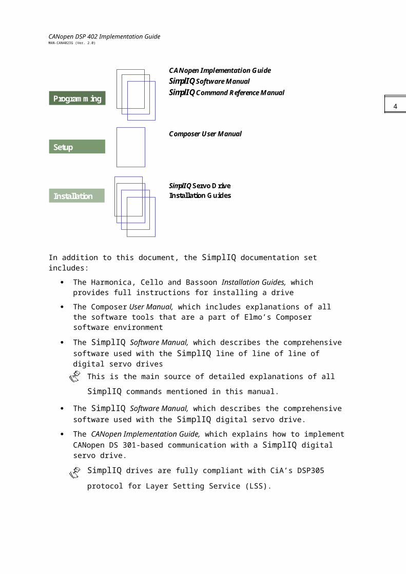
This manual – included in the Elmo CANopen Implementation Guide – is part of the Elmo SimplIQ digital servo drive documentation set, as outlined in the following diagram:
SimplIQ Servo DriveInstallation Guides
Programming
Setup
Installation
Composer User Manual
CANopen Implementation GuideSimplIQ Software ManualSimplIQ Command Reference Manual
In addition to this document, the SimplIQ documentation set includes:
The Harmonica, Cello and Bassoon Installation Guides, which provides full instructions for installing a drive
The Composer User Manual, which includes explanations of all the software tools that are a part of Elmo’s Composer software environment
The SimplIQ Software Manual, which describes the comprehensive software used with the SimplIQ line of line of line of digital servo drives
This is the main source of detailed explanations of all SimplIQ commands
mentioned in this manual.
The SimplIQ Software Manual, which describes the comprehensive software used with the SimplIQ digital servo drive.
The CANopen Implementation Guide, which explains how to implement CANopen DS 301-based communication with a SimplIQ digital servo drive.
SimplIQ drives are fully compliant with CiA’s DSP305 protocol for Layer Setting
Service (LSS).
3
CANopen DSP 402 Implementation GuideMAN-CAN402IG (Ver. 2.0)
4
CANopen DSP 402 Implementation GuideMAN-CAN402IG (Ver. 2.0)
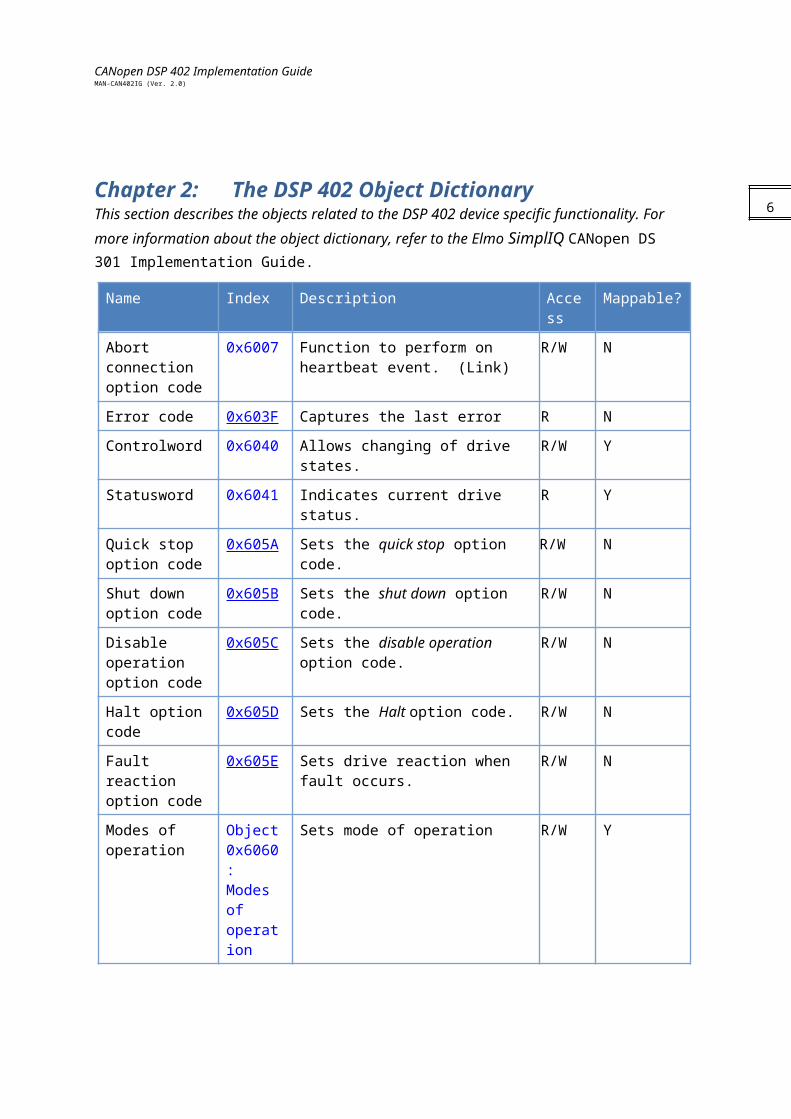
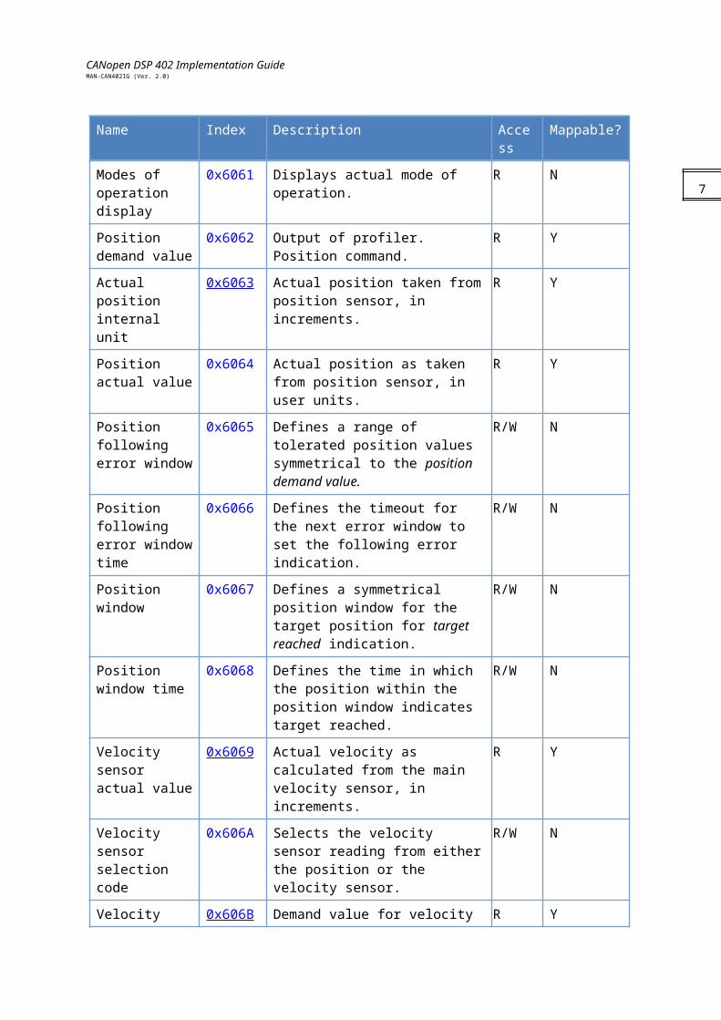
Chapter 2: The DSP 402 Object Dictionary This section describes the objects related to the DSP 402 device specific functionality. For more information about the object dictionary, refer to the Elmo SimplIQ CANopen DS 301 Implementation Guide.
Name Index Description Access Mappable?
Abort connection option code
0x6007 Function to perform on heartbeat event. (Link)
R/W N
Error code 0x603F Captures the last error R N
Controlword 0x6040 Allows changing of drive states. R/W Y
Statusword 0x6041 Indicates current drive status. R Y
Quick stop option code
0x605A Sets the quick stop option code. R/W N
Shut down option code
0x605B Sets the shut down option code. R/W N
Disable operation option code
0x605C Sets the disable operation option code. R/W N
Halt option code 0x605D Sets the Halt option code. R/W N
Fault reaction option code
0x605E Sets drive reaction when fault occurs. R/W N
Modes of operation
Object 0x6060: Modes ofoperation
Sets mode of operation R/W Y
Modes of operation display
0x6061 Displays actual mode of operation. R N
Position demand value
0x6062 Output of profiler. Position command. R Y
Actual position internal unit
0x6063 Actual position taken from position sensor, in increments.
R Y
Position actual value
0x6064 Actual position as taken from position sensor, in user units.
R Y
Position following error window
0x6065 Defines a range of tolerated position values symmetrical to the position demand value.
R/W N
Position following error window time
0x6066 Defines the timeout for the next error window to set the following error indication.
R/W N
5
CANopen DSP 402 Implementation GuideMAN-CAN402IG (Ver. 2.0)
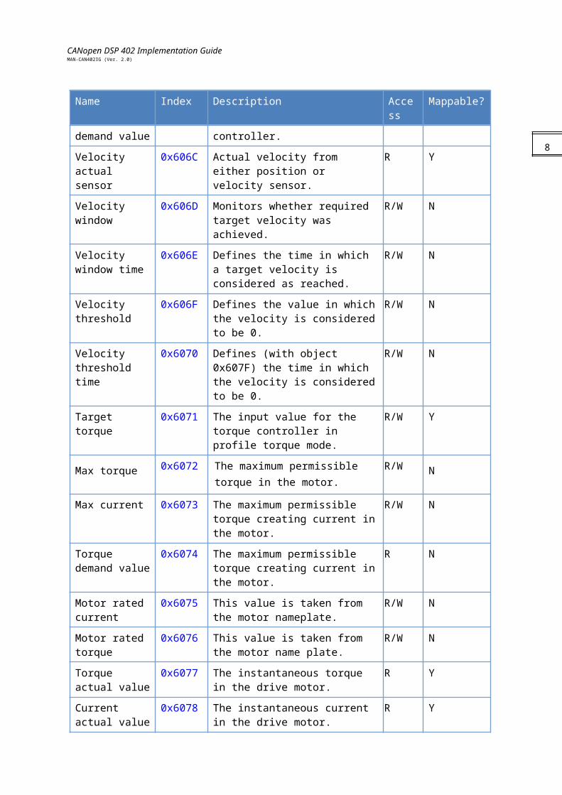
Name Index Description Access Mappable?
Position window 0x6067 Defines a symmetrical position window for the target position for target reached indication.
R/W N
Position window time
0x6068 Defines the time in which the position within the position window indicates target reached.
R/W N
Velocity sensor actual value
0x6069 Actual velocity as calculated from the main velocity sensor, in increments.
R Y
Velocity sensor selection code
0x606A Selects the velocity sensor reading from either the position or the velocity sensor.
R/W N
Velocity demand value
0x606B Demand value for velocity controller. R Y
Velocity actual sensor
0x606C Actual velocity from either position or velocity sensor.
R Y
Velocity window 0x606D Monitors whether required target velocity was achieved.
R/W N
Velocity window time
0x606E Defines the time in which a target velocity is considered as reached.
R/W N
Velocity threshold
0x606F Defines the value in which the velocity is considered to be 0.
R/W N
Velocity threshold time
0x6070 Defines (with object 0x607F) the time in which the velocity is considered to be 0.
R/W N
Target torque 0x6071 The input value for the torque controller in profile torque mode.
R/W Y
Max torque 0x6072 The maximum permissible torque in the motor.
R/W N
Max current 0x6073 The maximum permissible torque creating current in the motor.
R/W N
Torque demand value
0x6074 The maximum permissible torque creating current in the motor.
R N
Motor rated current
0x6075 This value is taken from the motor nameplate.
R/W N
Motor rated torque
0x6076 This value is taken from the motor name plate.
R/W N
Torque actual value
0x6077 The instantaneous torque in the drive motor.
R Y
Current actual 0x6078 The instantaneous current in the drive R Y
6

CANopen DSP 402 Implementation GuideMAN-CAN402IG (Ver. 2.0)
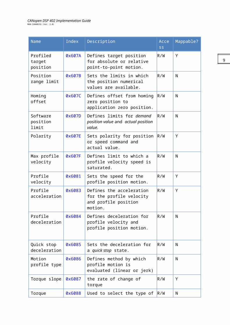
Name Index Description Access Mappable?
value motor.
Profiled target position
0x607A Defines target position for absolute or relative point-to-point motion.
R/W Y
Position range limit
0x607B Sets the limits in which the position numerical values are available.
R/W N
Homing offset 0x607C Defines offset from homing zero position to application zero position.
R/W N
Software position limit
0x607D Defines limits for demand position value and actual position value.
R/W N
Polarity 0x607E Sets polarity for position or speed command and actual value.
R/W Y
Max profile velocity
0x607F Defines limit to which a profile velocity speed is saturated.
R/W N
Profile velocity 0x6081 Sets the speed for the profile position motion.
R/W Y
Profile acceleration
0x6083 Defines the acceleration for the profile velocity and profile position motion.
R/W Y
Profile deceleration
0x6084 Defines deceleration for profile velocity and profile position motion.
R/W N
Quick stop deceleration
0x6085 Sets the deceleration for a quick stop state.
R/W N
Motion profile type
0x6086 Defines method by which profile motion is evaluated (linear or jerk)
R/W N
Torque slope 0x6087 the rate of change of torque R/W Y
Torque profile type
0x6088 Used to select the type of torque profile used to perform a torque change.
R/W N
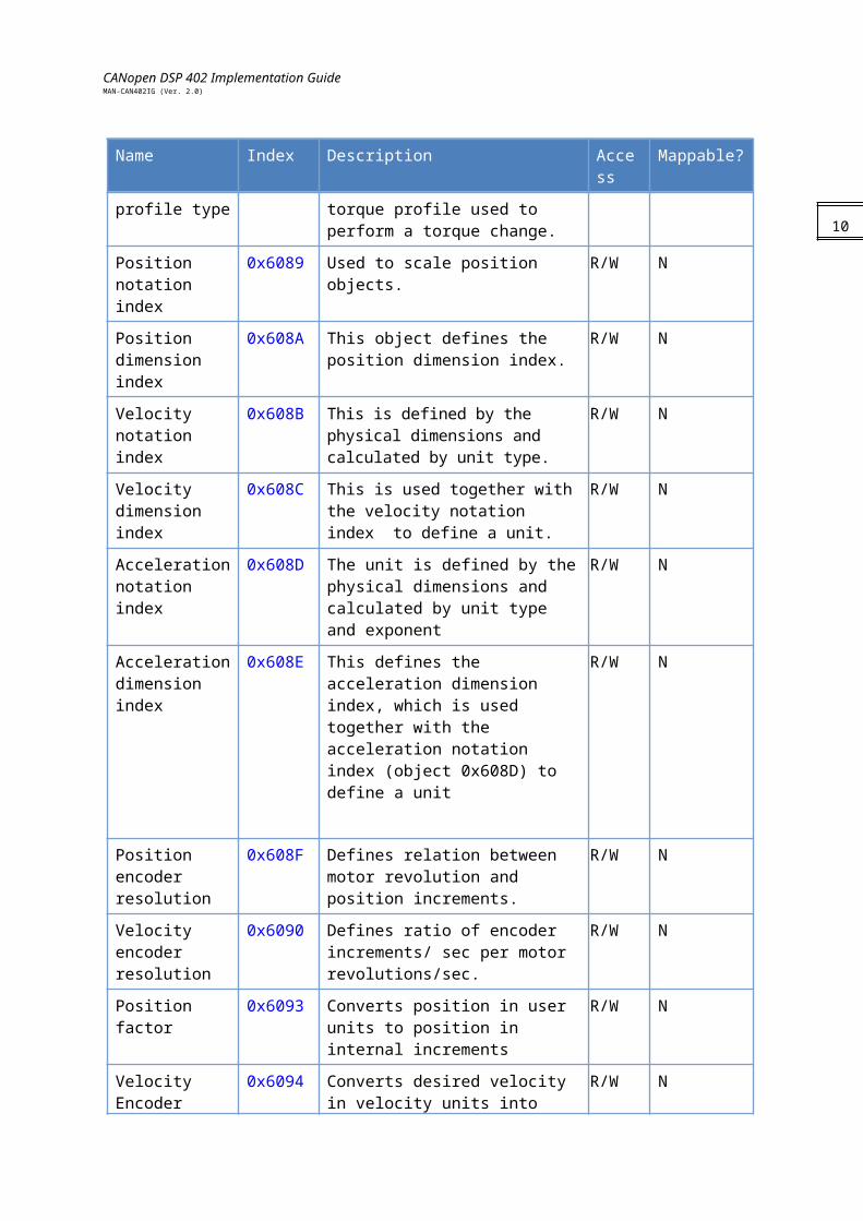
Position notation index
0x6089 Used to scale position objects. R/W N
Position dimension index
0x608A This object defines the position dimension index.
R/W N
Velocity notation index
0x608B This is defined by the physical dimensions and calculated by unit type.
R/W N
Velocity dimension index
0x608C This is used together with the velocity notation index to define a unit.
R/W N
Acceleration notation index
0x608D The unit is defined by the physical dimensions and calculated by unit type
R/W N
7
CANopen DSP 402 Implementation GuideMAN-CAN402IG (Ver. 2.0)
Name Index Description Access Mappable?
and exponent
Acceleration dimension index
0x608E This defines the acceleration dimension index, which is used together with the acceleration notation index (object 0x608D) to define a unit
R/W N
Position encoder resolution
0x608F Defines relation between motor revolution and position increments.
R/W N
Velocity encoder resolution
0x6090 Defines ratio of encoder increments/ sec per motor revolutions/sec.
R/W N
Position factor 0x6093 Converts position in user units to position in internal increments
R/W N
Velocity Encoder factor
0x6094 Converts desired velocity in velocity units into internal increments/sec.
R/W N
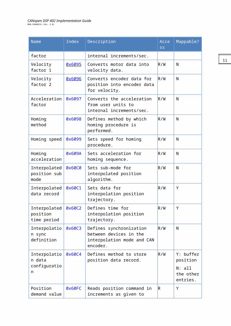
Velocity factor 1 0x6095 Converts motor data into velocity data.
R/W N
Velocity factor 2 0x6096 Converts encoder data for position into encoder data for velocity.
R/W N
Acceleration factor
0x6097 Converts the acceleration from user units to internal increments/sec.
R/W N
Homing method 0x6098 Defines method by which homing procedure is performed.
R/W N
Homing speed 0x6099 Sets speed for homing procedure. R/W N
Homing acceleration
0x609A Sets acceleration for homing sequence.
R/W N
Interpolated position sub mode
0x60C0 Sets sub-mode for interpolated position algorithm.
R/W N
Interpolated data record
0x60C1 Sets data for interpolation position trajectory.
R/W Y
Interpolated position time period
0x60C2 Defines time for interpolation position trajectory.
R/W Y
Interpolation sync definition
0x60C3 Defines synchronization between devices in the interpolation mode and CAN encoder.
R/W N
Interpolation data
0x60C4 Defines method to store position data record.
R/W Y: buffer position
8
CANopen DSP 402 Implementation GuideMAN-CAN402IG (Ver. 2.0)
Name Index Description Access Mappable?
configuration N: all the other entries.
Position demand value
0x60FC Reads position command in increments as given to position controller
R Y
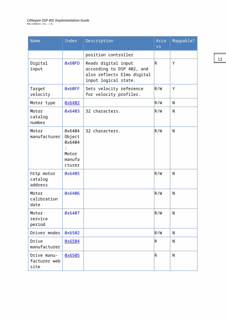
Digital input 0x60FD Reads digital input according to DSP 402, and also reflects Elmo digital input logical state.
R Y
Target velocity 0x60FF Sets velocity reference for velocity profiler.
R/W Y
Motor type 0x6402 R/W N
Motor catalog number
0x6403 32 characters. R/W N
Motor manufacturer
0x6404Object 0x6404: Motor manufacturer
32 characters. R/W N
http motor catalog address
0x6405 R/W N
Motor calibration date
0x6406 R/W N
Motor service period
0x6407 R/W N
Driver modes 0x6502 R/W N
Drive manufacturer
0x6504 R N
Drive manu-facturer web site
0x6505 R N
9
CANopen DSP 402 Implementation GuideMAN-CAN402IG (Ver. 2.0)
Chapter 3: EmergenciesEmergency messages are detailed in the SimplIQ CANopen Implementation Guide. 10
CANopen DSP 402 Implementation GuideMAN-CAN402IG (Ver. 2.0)
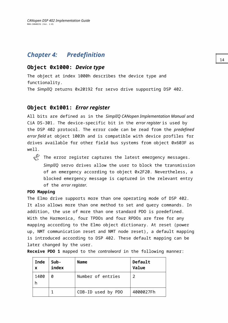
Chapter 4: PredefinitionObject 0x1000: Device typeThe object at index 1000h describes the device type and functionality.The SimplIQ returns 0x20192 for servo drive supporting DSP 402.
Object 0x1001: Error registerAll bits are defined as in the SimplIQ CANopen Implementation Manual and CiA DS-301. The device-specific bit in the error register is used by the DSP 402 protocol. The error code can be read from the predefined error field at object 1003h and is compatible with device profiles for drives available for other field bus systems from object 0x603F as well.
The error register captures the latest emergency messages. SimplIQ servo drives allow
the user to block the transmission of an emergency according to object 0x2F20. Nevertheless, a blocked emergency message is captured in the relevant entry of the error register.
PDO MappingThe Elmo drive supports more than one operating mode of DSP 402. It also allows more than one method to set and query commands. In addition, the use of more than one standard PDO is predefined. With the Harmonica, four TPDOs and four RPDOs are free for any mapping according to the Elmo object dictionary. At reset (power up, NMT communication reset and NMT node reset), a default mapping is introduced according to DSP 402. These default mapping can be later changed by the user.Receive PDO 1 mapped to the controlword in the following manner:
Index Sub-index Name Default Value
1400h 0 Number of entries 2
1 COB-ID used by PDO 4000027Fh
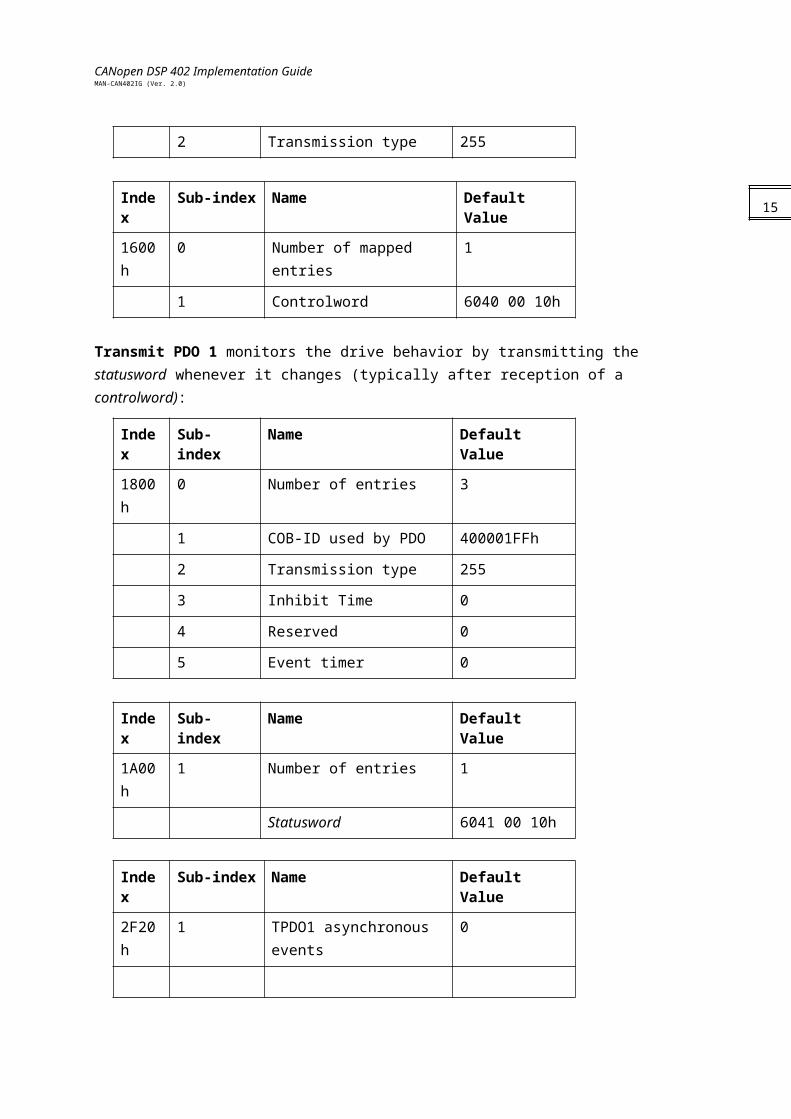
2 Transmission type 255
Index Sub-index Name Default Value
1600h 0 Number of mapped entries 1
1 Controlword 6040 00 10h
Transmit PDO 1 monitors the drive behavior by transmitting the statusword whenever it changes (typically after reception of a controlword):
Index Sub-index Name Default Value
11
CANopen DSP 402 Implementation GuideMAN-CAN402IG (Ver. 2.0)
1800h 0 Number of entries 3
1 COB-ID used by PDO 400001FFh
2 Transmission type 255
3 Inhibit Time 0
4 Reserved 0
5 Event timer 0
Index Sub-index Name Default Value
1A00h 1 Number of entries 1
Statusword 6041 00 10h
Index Sub-index Name Default Value
2F20h 1 TPDO1 asynchronous events 0
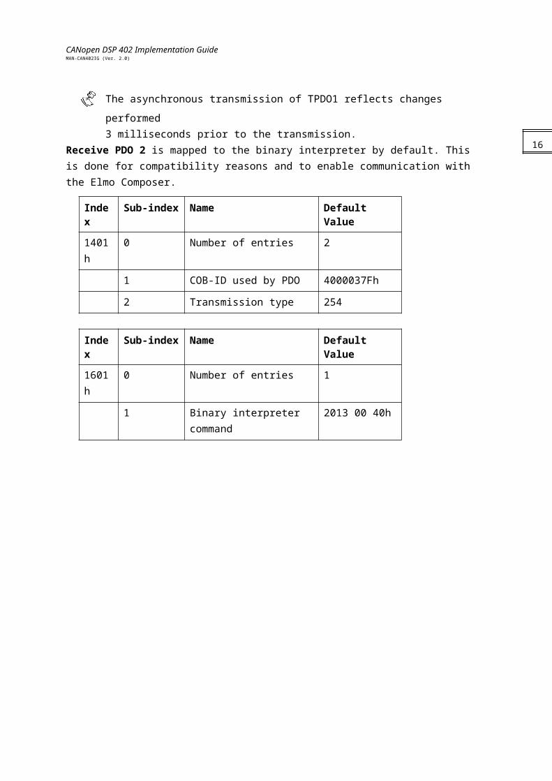
The asynchronous transmission of TPDO1 reflects changes performed
3 milliseconds prior to the transmission.Receive PDO 2 is mapped to the binary interpreter by default. This is done for compatibility reasons and to enable communication with the Elmo Composer.
Index Sub-index Name Default Value
1401h 0 Number of entries 2
1 COB-ID used by PDO 4000037Fh
2 Transmission type 254
Index Sub-index Name Default Value
1601h 0 Number of entries 1
1 Binary interpreter command 2013 00 40h
12
CANopen DSP 402 Implementation GuideMAN-CAN402IG (Ver. 2.0)
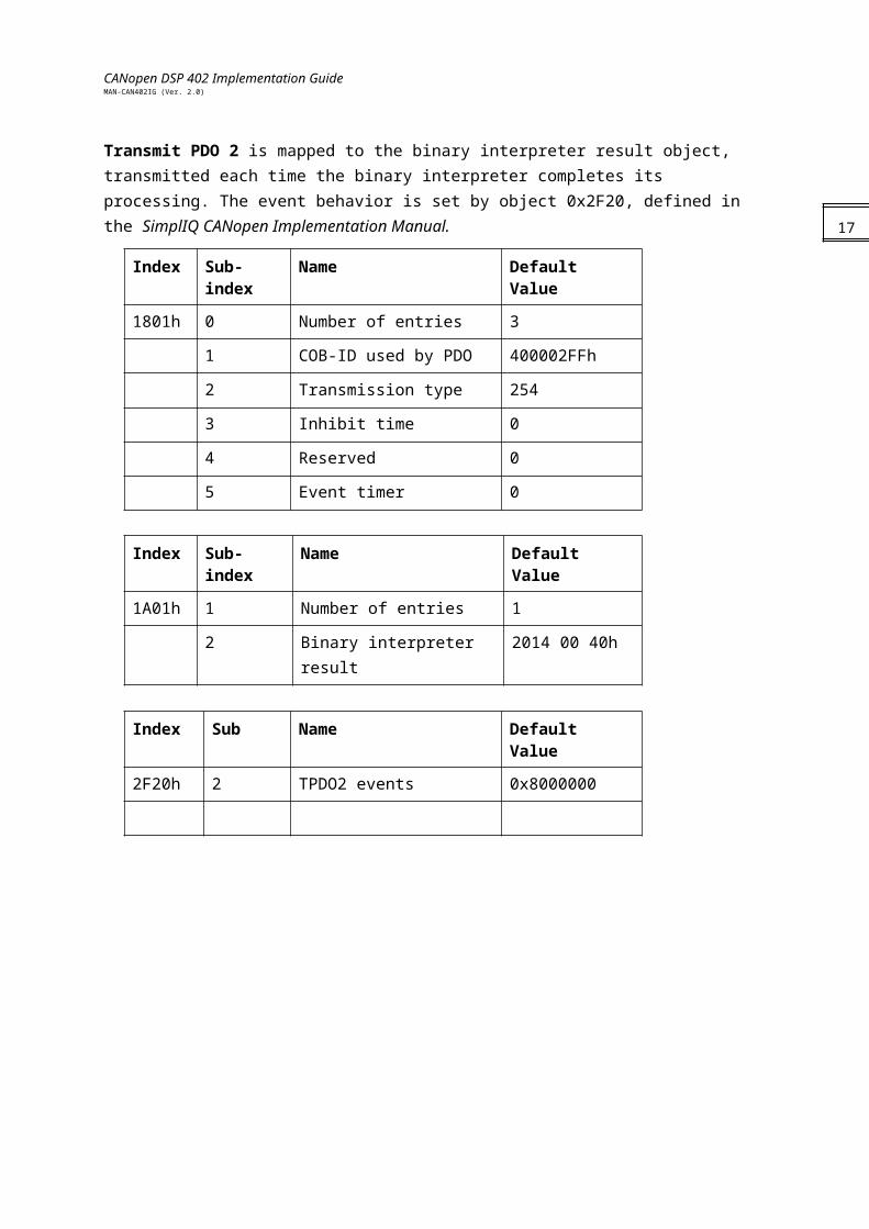
Transmit PDO 2 is mapped to the binary interpreter result object, transmitted each time the binary interpreter completes its processing. The event behavior is set by object 0x2F20, defined in the SimplIQ CANopen Implementation Manual.
Index Sub-index Name Default Value
1801h 0 Number of entries 3
1 COB-ID used by PDO 400002FFh
2 Transmission type 254
3 Inhibit time 0
4 Reserved 0
5 Event timer 0
Index Sub-index Name Default Value
1A01h 1 Number of entries 1
2 Binary interpreter result 2014 00 40h
Index Sub Name Default Value
2F20h 2 TPDO2 events 0x8000000
13
CANopen DSP 402 Implementation GuideMAN-CAN402IG (Ver. 2.0)
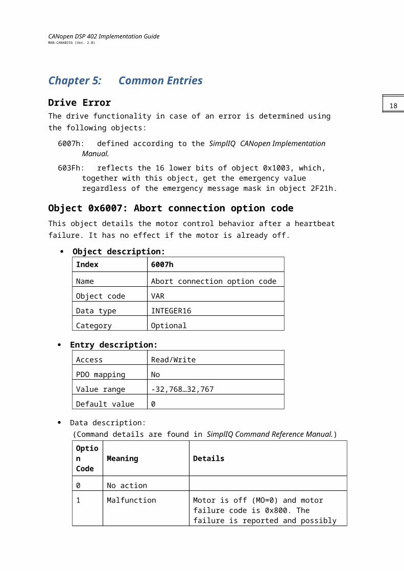
Chapter 5: Common Entries Drive ErrorThe drive functionality in case of an error is determined using the following objects:
6007h: defined according to the SimplIQ CANopen Implementation Manual.
603Fh: reflects the 16 lower bits of object 0x1003, which, together with this object, get the emergency value regardless of the emergency message mask in object 2F21h.
Object 0x6007: Abort connection option codeThis object details the motor control behavior after a heartbeat failure. It has no effect if the motor is already off.
Object description:Index 6007h
Name Abort connection option code
Object code VAR
Data type INTEGER16
Category Optional
Entry description:Access Read/Write
PDO mapping No
Value range -32,768…32,767
Default value 0
Data description:(Command details are found in SimplIQ Command Reference Manual.)
Option Code Meaning Details
0 No action
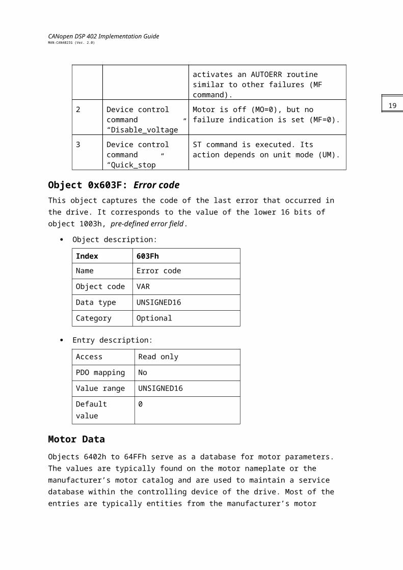
1 Malfunction Motor is off (MO=0) and motor failure code is 0x800. The failure is reported and possibly activates an AUTOERR routine similar to other failures (MF command).
2 Device control command “Disable_voltage”
Motor is off (MO=0), but no failure indication is set (MF=0).
3 Device control command “Quick_stop”
ST command is executed. Its action depends on unit mode (UM).
14

CANopen DSP 402 Implementation GuideMAN-CAN402IG (Ver. 2.0)
Object 0x603F: Error codeThis object captures the code of the last error that occurred in the drive. It corresponds to the value of the lower 16 bits of object 1003h, pre-defined error field.
Object description:
Index 603Fh
Name Error code
Object code VAR
Data type UNSIGNED16
Category Optional
Entry description:
Access Read only
PDO mapping No
Value range UNSIGNED16
Default value 0
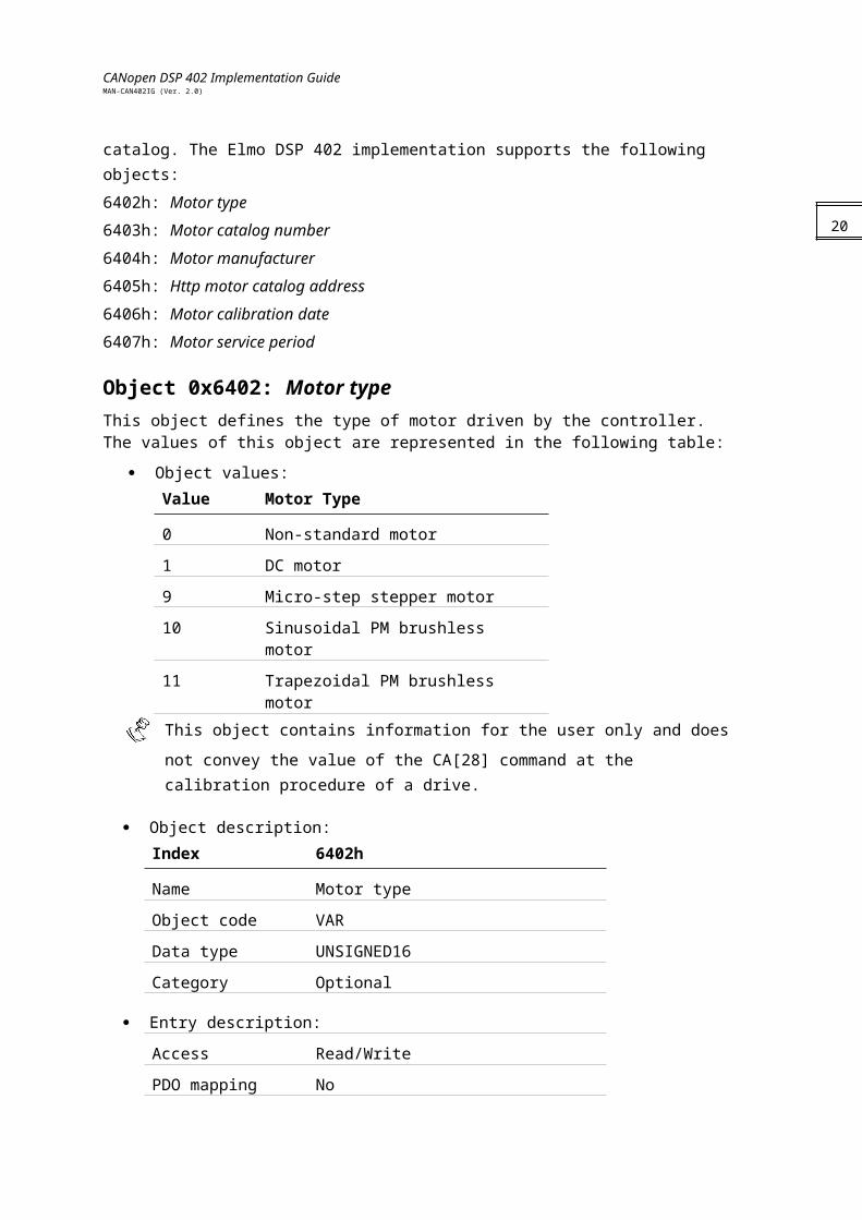
Motor Data Objects 6402h to 64FFh serve as a database for motor parameters. The values are typically found on the motor nameplate or the manufacturer’s motor catalog and are used to maintain a service database within the controlling device of the drive. Most of the entries are typically entities from the manufacturer’s motor catalog. The Elmo DSP 402 implementation supports the following objects:6402h: Motor type6403h: Motor catalog number6404h: Motor manufacturer6405h: Http motor catalog address6406h: Motor calibration date6407h: Motor service period
Object 0x6402: Motor typeThis object defines the type of motor driven by the controller. The values of this object are represented in the following table:
Object values:Value Motor Type
0 Non-standard motor
1 DC motor
15
CANopen DSP 402 Implementation GuideMAN-CAN402IG (Ver. 2.0)
9 Micro-step stepper motor
10 Sinusoidal PM brushless motor
11 Trapezoidal PM brushless motor
This object contains information for the user only and does not convey the value of the
CA[28] command at the calibration procedure of a drive.
Object description:Index 6402h
Name Motor type
Object code VAR
Data type UNSIGNED16
Category Optional
Entry description:
Access Read/Write
PDO mapping No
Value range UNSIGNED16
Default value
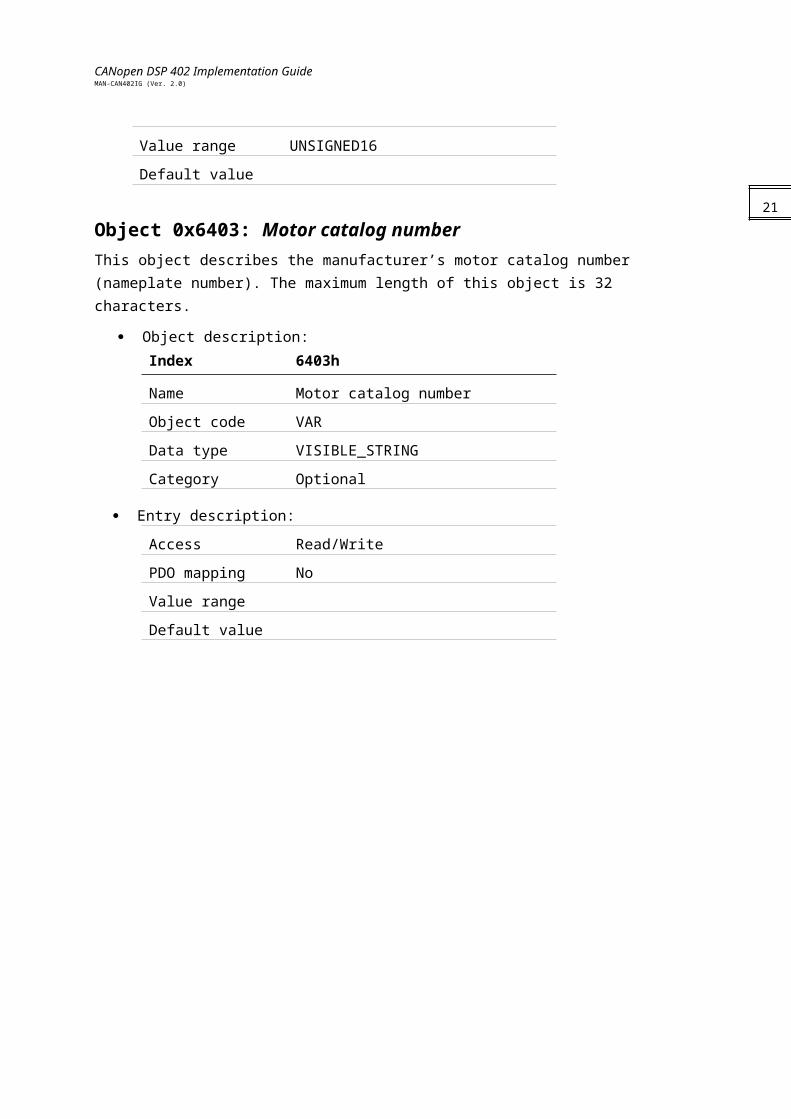
Object 0x6403: Motor catalog numberThis object describes the manufacturer’s motor catalog number (nameplate number). The maximum length of this object is 32 characters.
Object description:Index 6403h
Name Motor catalog number
Object code VAR
Data type VISIBLE_STRING
Category Optional
Entry description:
Access Read/Write
PDO mapping No
Value range
Default value
16
CANopen DSP 402 Implementation GuideMAN-CAN402IG (Ver. 2.0)
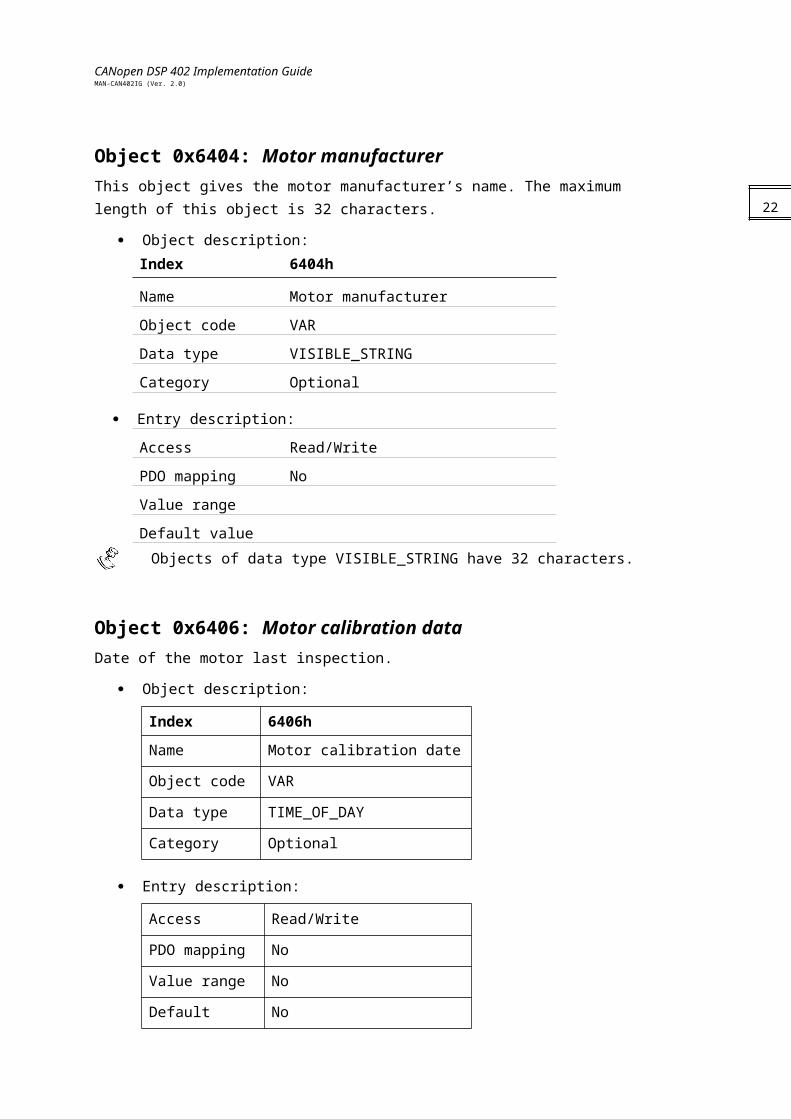
Object 0x6404: Motor manufacturerThis object gives the motor manufacturer’s name. The maximum length of this object is 32 characters.
Object description:Index 6404h
Name Motor manufacturer
Object code VAR
Data type VISIBLE_STRING
Category Optional
Entry description:
Access Read/Write
PDO mapping No
Value range
Default value
Objects of data type VISIBLE_STRING have 32 characters.
Object 0x6406: Motor calibration dataDate of the motor last inspection.
Object description:
Index 6406h
Name Motor calibration date
Object code VAR
Data type TIME_OF_DAY
Category Optional
Entry description:
Access Read/Write
PDO mapping No
Value range No
Default value No
17
CANopen DSP 402 Implementation GuideMAN-CAN402IG (Ver. 2.0)
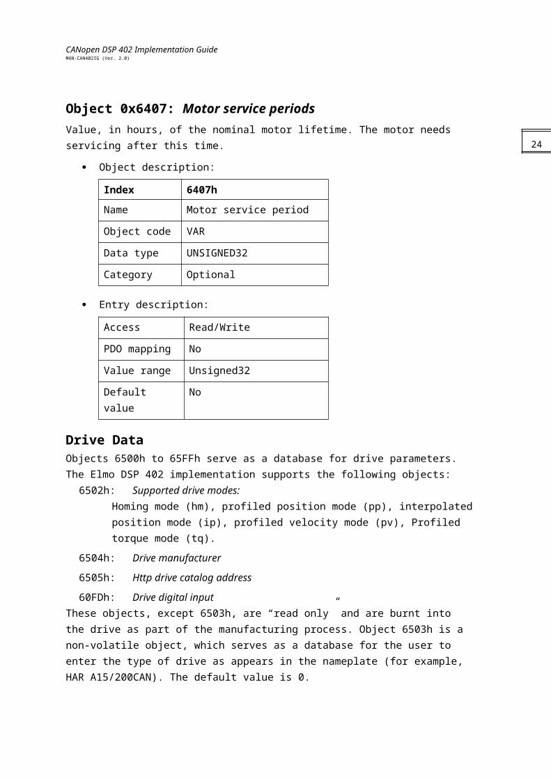
Object 0x6407: Motor service periodsValue, in hours, of the nominal motor lifetime. The motor needs servicing after this time.
Object description:
Index 6407h
Name Motor service period
Object code VAR
Data type UNSIGNED32
Category Optional
Entry description:
Access Read/Write
PDO mapping No
Value range Unsigned32
Default value No
Drive DataObjects 6500h to 65FFh serve as a database for drive parameters. The Elmo DSP 402 implementation supports the following objects:
6502h: Supported drive modes: Homing mode (hm), profiled position mode (pp), interpolated position mode (ip), profiled velocity mode (pv), Profiled torque mode (tq).
6504h: Drive manufacturer
6505h: Http drive catalog address
60FDh: Drive digital inputThese objects, except 6503h, are “read only” and are burnt into the drive as part of the manufacturing process. Object 6503h is a non-volatile object, which serves as a database for the user to enter the type of drive as appears in the nameplate (for example,HAR A15/200CAN). The default value is 0.
The following objects provide more information about the drive:
1008h: Manufacturer device name
100Ah: Manufacturer software version
18
CANopen DSP 402 Implementation GuideMAN-CAN402IG (Ver. 2.0)
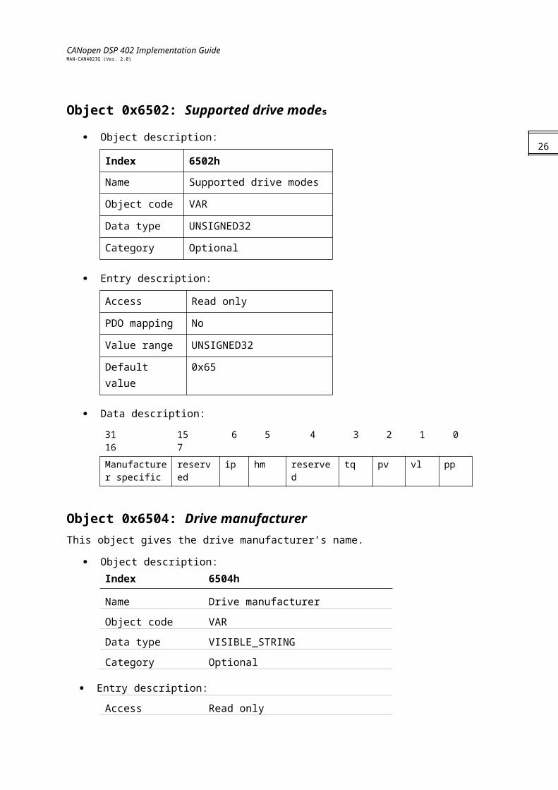
Object 0x6502: Supported drive modes
Object description:
Index 6502h
Name Supported drive modes
Object code VAR
Data type UNSIGNED32
Category Optional
Entry description:
Access Read only
PDO mapping No
Value range UNSIGNED32
Default value 0x65
Data description:
31 16 15 7 6 5 4 3 2 1 0
Manufacturer specific
reserved ip hm reserved tq pv vl pp
Object 0x6504: Drive manufacturerThis object gives the drive manufacturer’s name.
Object description:Index 6504h
Name Drive manufacturer
Object code VAR
Data type VISIBLE_STRING
Category Optional
Entry description:
Access Read only
PDO mapping No
Value range
Default value Elmo Motion Control Ltd.
19
CANopen DSP 402 Implementation GuideMAN-CAN402IG (Ver. 2.0)
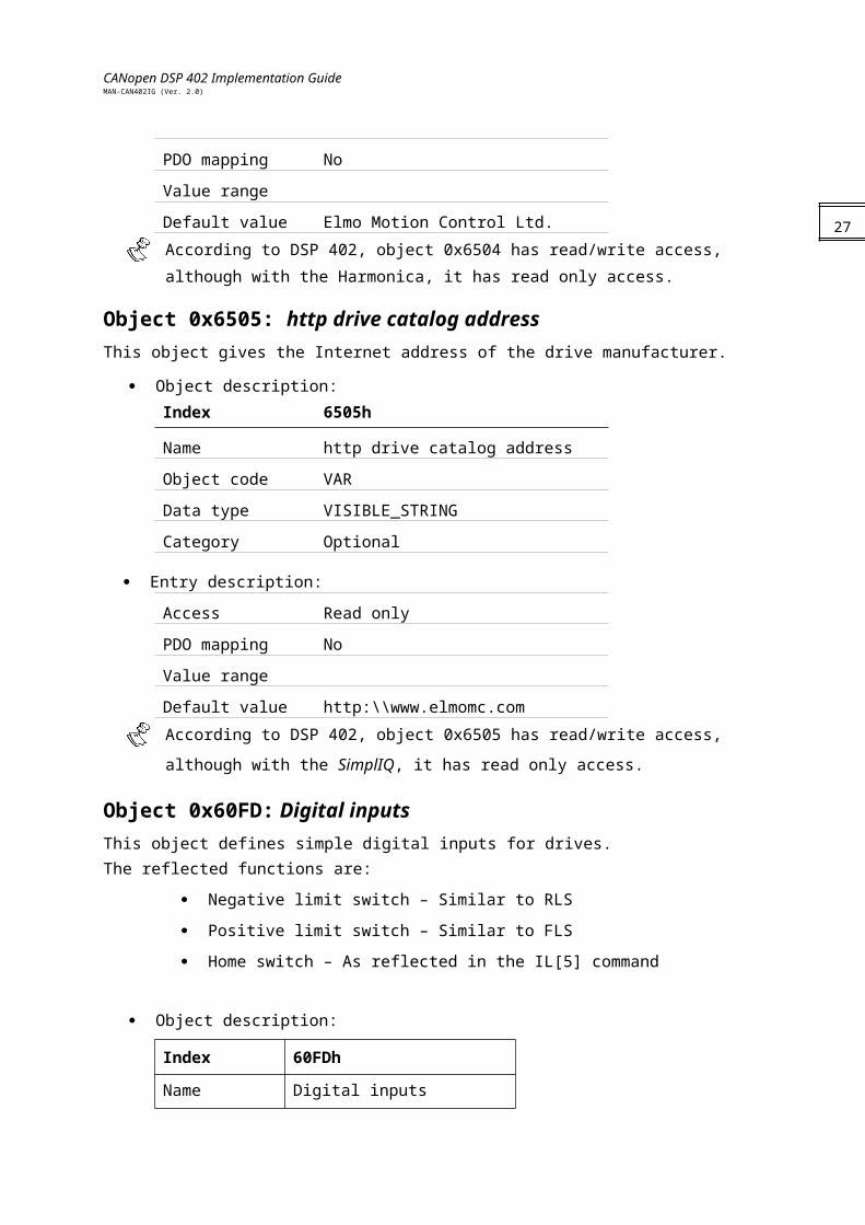
According to DSP 402, object 0x6504 has read/write access, although with the
Harmonica, it has read only access.
Object 0x6505: http drive catalog addressThis object gives the Internet address of the drive manufacturer.
Object description:Index 6505h
Name http drive catalog address
Object code VAR
Data type VISIBLE_STRING
Category Optional
Entry description:
Access Read only
PDO mapping No
Value range
Default value http:\\www.elmomc.com
According to DSP 402, object 0x6505 has read/write access, although with the SimplIQ, it
has read only access.
Object 0x60FD: Digital inputsThis object defines simple digital inputs for drives. The reflected functions are:
Negative limit switch – Similar to RLS
Positive limit switch – Similar to FLS
Home switch – As reflected in the IL[5] command
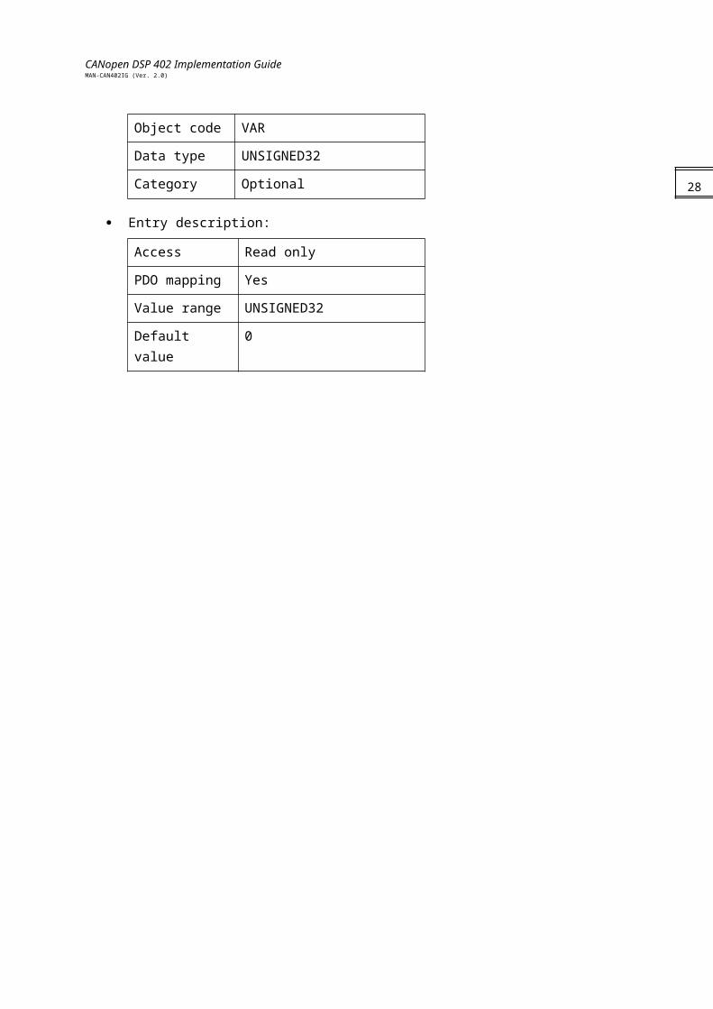
Object description:
Index 60FDh
Name Digital inputs
Object code VAR
Data type UNSIGNED32
Category Optional
Entry description:
Access Read only
20
CANopen DSP 402 Implementation GuideMAN-CAN402IG (Ver. 2.0)
PDO mapping Yes
Value range UNSIGNED32
Default value 0 21
CANopen DSP 402 Implementation GuideMAN-CAN402IG (Ver. 2.0)
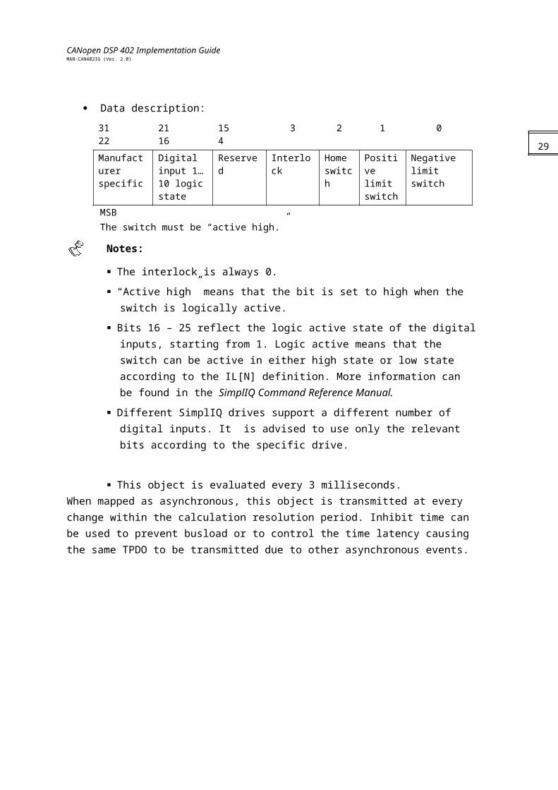
Data description:
31 22 21 16 15 4 3 2 1 0
Manufacturer specific
Digital input 1…10 logic state
Reserved Interlock Home switch
Positive limit switch
Negative limit switch
MSBThe switch must be “active high.”
Notes:
The interlock is always 0.
“Active high” means that the bit is set to high when the switch is logically active.
Bits 16 – 25 reflect the logic active state of the digital inputs, starting from 1. Logic active means that the switch can be active in either high state or low state according to the IL[N] definition. More information can be found in the SimplIQ Command Reference Manual.
Different SimplIQ drives support a different number of digital inputs. It is advised to use only the relevant bits according to the specific drive.
This object is evaluated every 3 milliseconds.When mapped as asynchronous, this object is transmitted at every change within the calculation resolution period. Inhibit time can be used to prevent busload or to control the time latency causing the same TPDO to be transmitted due to other asynchronous events.
22
CANopen DSP 402 Implementation GuideMAN-CAN402IG (Ver. 2.0)
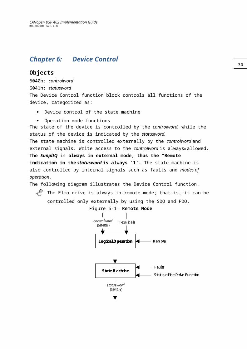
Chapter 6: Device ControlObjects6040h: controlword 6041h: statusword The Device Control function block controls all functions of the device, categorized as:
Device control of the state machine
Operation mode functionsThe state of the device is controlled by the controlword, while the status of the device is indicated by the statusword.The state machine is controlled externally by the controlword and external signals. Write access to the controlword is always allowed. The SimplIQ is always in external mode, thus the “Remote” indication in the statusword is always ‘1’. The state machine is also controlled by internal signals such as faults and modes of operation.The following diagram illustrates the Device Control function.
The Elmo drive is always in remote mode; that is, it can be controlled only externally by
using the SDO and PDO.Figure 6-1: Remote Mode
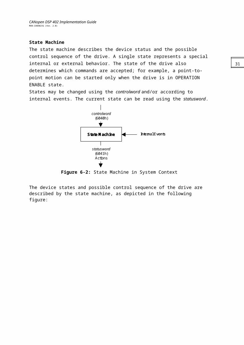
State MachineThe state machine describes the device status and the possible control sequence of the drive. A single state represents a special internal or external behavior. The state of the drive also determines which commands are accepted; for example, a point-to-point motion can be started only when the drive is in OPERATION ENABLE state.
23
State Machine
controlword(6040h)
Terminals
Logical Operation
statusword(6041h)
Remote
Faults
Status of the Drive FunctionState MachineState Machine
controlword(6040h)
Terminals
Logical OperationLogical Operation
statusword(6041h)
Remote
Faults
Status of the Drive Function
CANopen DSP 402 Implementation GuideMAN-CAN402IG (Ver. 2.0)
States may be changed using the controlword and/or according to internal events. The current state can be read using the statusword.
Figure 6-2: State Machine in System Context
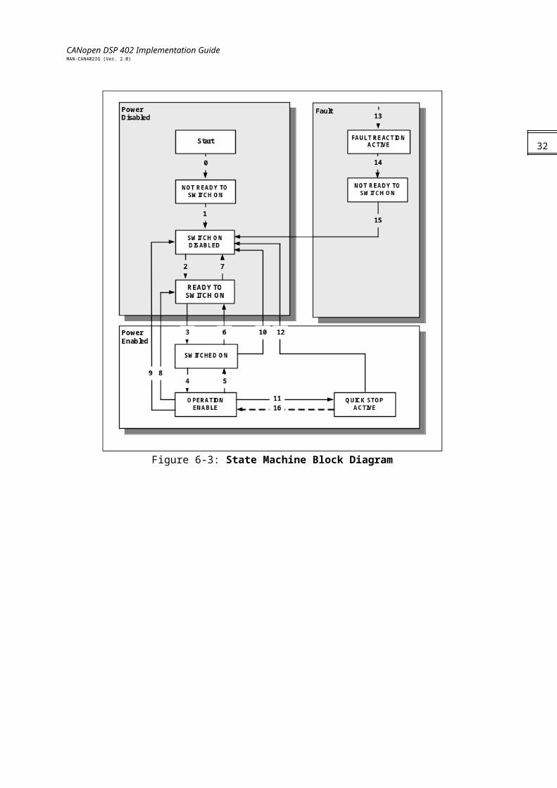
The device states and possible control sequence of the drive are described by the state machine, as depicted in the following figure:
Figure 6-3: State Machine Block Diagram
24
State Machine
statusword(6041h)Actions
Internal Events
controlword(6040h)
State MachineState Machine
statusword(6041h)Actions
Internal Events
controlword(6040h)

CANopen DSP 402 Implementation GuideMAN-CAN402IG (Ver. 2.0)
Drive StatesThe following states of the device are possible:
* NOT READY TO SWITCH ON:Low-level power (24V) has been applied to the drive.The drive is being initialized and is running the self test.A brake output, if present, is applied in this state.The drive function is disabled.
This state is an internal state in which communication is enabled only at the end.
The user can neither retrieve nor monitor this state.
* SWITCH ON DISABLED:Drive initialization is complete.The drive parameters have been set up.Drive parameters may be changed.High voltage may not be applied to the drive, (such as for safety reasons; refer to following note).The drive function is disabled.
Notes:
In this state, if high power is applied anyway, no indication of an error is given. The application must be responsible for handling the state transition.
SWITCH ON DISABLED is the minimum state to which a user may switch.
* READY TO SWITCH ON:High voltage may be applied to the drive.The drive parameters may be changed.The drive function is disabled.
* SWITCHED ON:High voltage has been applied to the drive.The power amplifier is ready.The drive parameters may be changed.The drive function is disabled.
No indication is given if the drive high voltage has not been applied.
* OPERATION ENABLE:No faults have been detected.The drive function is enabled and power is applied to the motor.The drive parameters may be changed.(This corresponds to normal operation of the drive.)
In this state, a brake is automatically released according to the brake parameter
(BP[N]) timing.
25
CANopen DSP 402 Implementation GuideMAN-CAN402IG (Ver. 2.0)
* QUICK STOP ACTIVE:The drive parameters may be changed.The quick stop function is being executed.The drive function is enabled and power is applied to the motor.
According to the quick stop option code, the drive stops the motion and either stays in quick stop or disables the motor. The term “drive stops” means that the rfg completed the deceleration trajectory and not that the motor is stationary.
If the quick stop option code (object 0x605A) is 0 (disable drive function), the state of the drive is SWITCH ON DISABLED.
* FAULT REACTION ACTIVE:The drive parameters may be changed.A fault has occurred in the drive.The fault reaction function is being executed.The drive function is disabled.
This parameter cannot be retrieved by the user. The drive automatically switches
to FAULT state.
* FAULT:The drive parameters may be changed.A fault has occurred in the drive.High voltage switch-on/-off depends on the application.The drive function is disabled.
State Transitions of the Drive SupervisorState transitions are caused by internal events in the drive or by commands from the host via the controlword.
State Transition 0: START => NOT READY TO SWITCH ONEvent: Reset.Action: The drive self-tests and/or self-initializes.
State Transition 1: NOT READY TO SWITCH ON => SWITCH ON DISABLEDEvent: The drive has self-tested and/or initialized successfully.Action: Activate communication.
State Transition 2: SWITCH ON DISABLED => READY TO SWITCH ONEvent: Shutdown command received from host.Action: None
State Transition 3: READY TO SWITCH ON => SWITCHED ONEvent: Switch On command received from host.Action: The power section is switched on if it is not already on.
State Transition 4: SWITCHED ON => OPERATION ENABLEEvent: Enable Operation command received from host.Action: The drive function is enabled.
26

CANopen DSP 402 Implementation GuideMAN-CAN402IG (Ver. 2.0)
State Transition 5: OPERATION ENABLE => SWITCHED ONEvent: Disable Operation command received from host.Action: The drive operation is disabled.
State Transition 6: SWITCHED ON => READY TO SWITCH ONEvent: Shutdown command received from host.Action: The power section is switched off.
State Transition 7: READY TO SWITCH ON => SWITCH ON DISABLEDEvent: Quick Stop and Disable Voltage commands received from host.Action: None.
State Transition 8: OPERATION ENABLE => READY TO SWITCH ONEvent: Shutdown command received from host.Action: The power section is switched off immediately, and the motor is free to rotate if not braked.
State Transition 9: OPERATION ENABLE => SWITCH ON DISABLEDEvent: Disable Voltage command received from host.Action: The power section is switched off immediately, and the motor is free to rotate if not braked.
State Transition 10: SWITCHED ON =>SWITCH ON DISABLEDEvent: Disable Voltage or Quick Stop command received from host.Action: The power section is switched off immediately, and the motor is free to rotate if not braked.
State Transition 11: OPERATION ENABLE =>QUICK STOP ACTIVEEvent: Quick Stop command received from host.Action: The quick stop function is executed.
State Transition 12: QUICK STOP ACTIVE=>SWITCH ON DISABLEDEvent: Quick Stop completed or Disable Voltage command received from host.This transition is possible if the quick stop option code is higher than 5 (stay in QUICK STOP ACTIVE state).Action: The profile generator finished the deceleration and the motor is disabled.
State Transition 13: All => FAULT REACTION ACTIVEEvent: A fault has occurred in the drive.Action: Execute appropriate fault reaction.
State Transition 14: FAULT REACTION ACTIVE => FAULTEvent: The fault reaction is completed.Action: The drive function is disabled. The power section may be switched off.
State Transition 15: FAULT=>SWITCH ON DISABLEDEvent: Fault Reset command received from host.Action: The fault condition is reset if no fault currently exists in the drive.
After leaving FAULT state, the Fault Reset bit of the controlword must be cleared by
the host. The drive does not monitor this bit in other states. If this bit is not cleared from a previous fault state, when the next fault occurs, the drive automatically enters SWITCH ON DISABLED state with no indications or warning.
State Transition 16: QUICK STOP ACTIVE=>OPERATION ENABLEEvent: Enable Operation command received from host. This transition is possible if the
27
CANopen DSP 402 Implementation GuideMAN-CAN402IG (Ver. 2.0)
quick stop option code (object 0x605A) is 5, 6.Action: The drive function is enabled.
Notes:
This transition forces a “motion begin”; for example, if the controlword forces transition 11 during a home sequence, the motor will stop according to the quick stop option code. If a new homing speed and homing acceleration are set to the drive and the controlword sets transition 16, the home sequence will continue according to the method and with the new home parameters.
If the motor is turned off by an external source (such as the interpreter) during OPERATION ENABLE, the minimum state SWITCH ON ENABLE will merge with no further notification.
Important Notes about State Transition:
If a command that causes a change of state is received, it is processed completely and the new state is attained before the next command is processed.
The drive performs transitions 0 and 1 after initiation, either at power up or at NMT node reset. From this state, it is up to the host to change the transitions according to the application needs.
“Drive function is disabled” implies that no energy is being supplied to the motor. Reference values are not processed.
“Drive function is enabled” implies that energy can be supplied to the motor. The reference values (torque, velocity and position) are processed.
“Fault occurred” implies that a fault has occurred in the drive during “Operation Enable”. In this case, there is a transition to state FAULT REACTION ACTIVE, during which the device executes a motor disable function. After executing this fault reaction, the device switches to state FAULT. It is possible to leave this state only through the Fault Reset command, and only if the fault is not active anymore.
If a fault occurs in OPERATION ENABLE state, an emergency message – if not masked – is sent with the fault reason. The last 16 fault messages are latched and can be retrieved later by uploading object 0x1003, defined in DS-301.
In a fault state, setting MO=1 through methods other than the controlword activates the motor and leads to an ambiguous state of the DSP 402 protocol.
Illegal TransitionAfter initiation of a drive by either power on or NMT node reset, the drive automatically performs transitions 0 and 1 to the SWITCH ON DISABLED state. The controlword can then be used to cause any of the transitions defined previously. If a transition is illegal (such as requesting a QUICK STOP in a FAULT state), the controlword is rejected with abort code 0609 0030, “Value range of parameter exceeded.” If an RPDO is used to control the drive, an RPDO style emergency is transmitted with the error code. The emergency structure and meaning is illustrated in the SimplIQ CANopen Implementation Manual. This emergency can be masked in accordance with
28
CANopen DSP 402 Implementation GuideMAN-CAN402IG (Ver. 2.0)
object 2F21h. In case of an illegal transition, bit 7 in the statusword (warning) is set for at least the next transmission of this statusword. The bit is after a legal transition of the controlword.
The resolution for statusword transmission is approximately 3 milliseconds. Events that
are modified during this time are sensed and responded to, but no notification of them is made by the statusword.
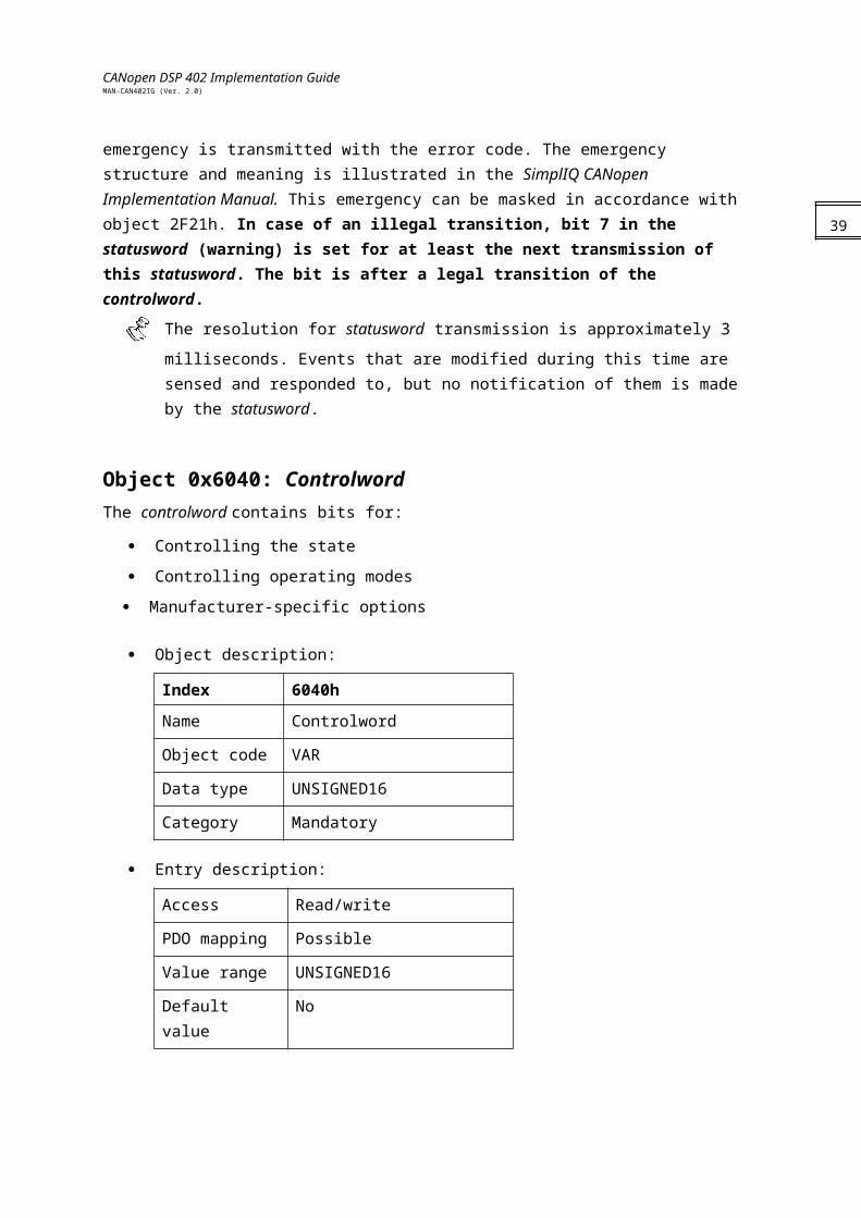
Object 0x6040: ControlwordThe controlword contains bits for:
Controlling the state
Controlling operating modes
Manufacturer-specific options
Object description:
Index 6040h
Name Controlword
Object code VAR
Data type UNSIGNED16
Category Mandatory
Entry description:
Access Read/write
PDO mapping Possible
Value range UNSIGNED16
Default value No
29
CANopen DSP 402 Implementation GuideMAN-CAN402IG (Ver. 2.0)
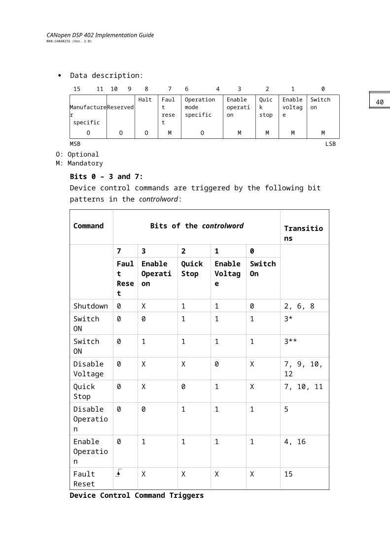
Data description:
15 11 10 9 8 7 6 4 3 2 1 0
Manufacturer specific
Reserved Halt Fault reset
Operation mode specific
Enable operation
Quick stop
Enable voltage
Switch on
O O O M O M M M M
MSB LSB
O: OptionalM: Mandatory
Bits 0 – 3 and 7:Device control commands are triggered by the following bit patterns in the controlword:
Command Bits of the controlword Transitions
7 3 2 1 0
Fault Reset
Enable Operation
Quick Stop
Enable Voltage
Switch On
Shutdown 0 X 1 1 0 2, 6, 8
Switch ON 0 0 1 1 1 3*
Switch ON 0 1 1 1 1 3**
Disable Voltage
0 X X 0 X 7, 9, 10, 12
Quick Stop 0 X 0 1 X 7, 10, 11
Disable Operation
0 0 1 1 1 5
Enable Operation
0 1 1 1 1 4, 16
Fault Reset X X X X 15
Device Control Command Triggers
Bits marked with X are not relevant.
* The drive executes the functionality of SWITCH_ON.
** The drive does nothing in this state, which is treated the same as in *.
30
CANopen DSP 402 Implementation GuideMAN-CAN402IG (Ver. 2.0)
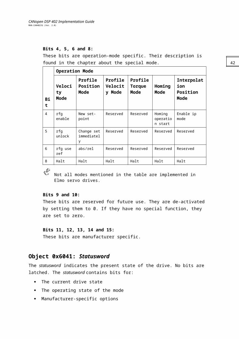
Bits 4, 5, 6 and 8:These bits are operation-mode specific. Their description is found in the chapter about the special mode.
Bit
Operation Mode
Velocity Mode
Profile Position Mode
Profile Velocity Mode
Profile Torque Mode
Homing Mode
Interpolation Position Mode
4 rfg enable New set-point Reserved Reserved Homing operation start
Enable ip mode
5 rfg unlock Change set immediately
Reserved Reserved Reserved Reserved
6 rfg use ref abs/rel Reserved Reserved Reserved Reserved
8 Halt Halt Halt Halt Halt Halt
Not all modes mentioned in the table are implemented in Elmo servo drives.
Bits 9 and 10:These bits are reserved for future use. They are de-activated by setting them to 0. If they have no special function, they are set to zero.
Bits 11, 12, 13, 14 and 15:These bits are manufacturer specific.
Object 0x6041: Statusword The statusword indicates the present state of the drive. No bits are latched. The statusword contains bits for:
The current drive state
The operating state of the mode
Manufacturer-specific options
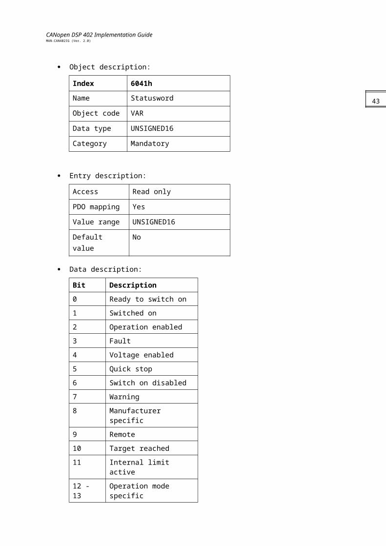
Object description:
Index 6041h
Name Statusword
Object code VAR
Data type UNSIGNED16
31
CANopen DSP 402 Implementation GuideMAN-CAN402IG (Ver. 2.0)
Category Mandatory
Entry description:
Access Read only
PDO mapping Yes
Value range UNSIGNED16
Default value No
Data description:
Bit Description
0 Ready to switch on
1 Switched on
2 Operation enabled
3 Fault
4 Voltage enabled
5 Quick stop
6 Switch on disabled
7 Warning
8 Manufacturer specific
9 Remote
10 Target reached
11 Internal limit active
12 - 13 Operation mode specific
14 - 15 Manufacturer specific
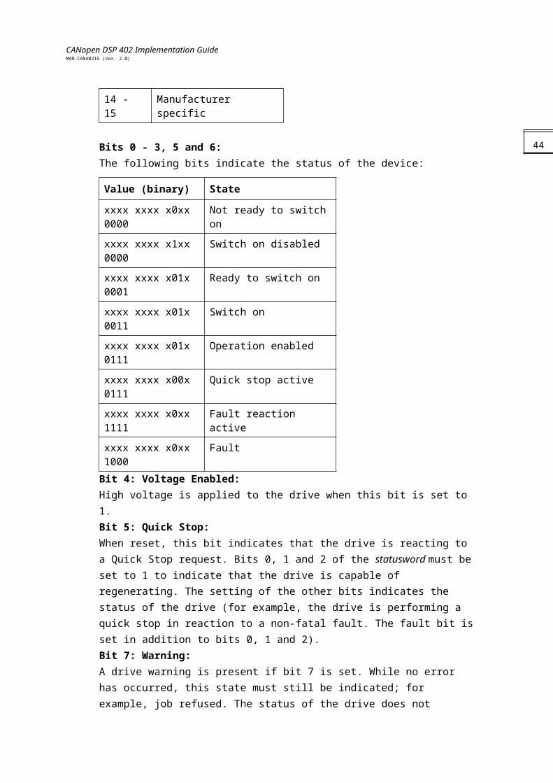
Bits 0 - 3, 5 and 6:The following bits indicate the status of the device:
Value (binary) State
xxxx xxxx x0xx 0000 Not ready to switch on
xxxx xxxx x1xx 0000 Switch on disabled
xxxx xxxx x01x 0001 Ready to switch on
xxxx xxxx x01x 0011 Switch on
xxxx xxxx x01x 0111 Operation enabled
32
CANopen DSP 402 Implementation GuideMAN-CAN402IG (Ver. 2.0)
xxxx xxxx x00x 0111 Quick stop active
xxxx xxxx x0xx 1111 Fault reaction active
xxxx xxxx x0xx 1000 FaultBit 4: Voltage Enabled:High voltage is applied to the drive when this bit is set to 1. Bit 5: Quick Stop:When reset, this bit indicates that the drive is reacting to a Quick Stop request. Bits 0, 1 and 2 of the statusword must be set to 1 to indicate that the drive is capable of regenerating. The setting of the other bits indicates the status of the drive (for example, the drive is performing a quick stop in reaction to a non-fatal fault. The fault bit is set in addition to bits 0, 1 and 2).Bit 7: Warning:A drive warning is present if bit 7 is set. While no error has occurred, this state must still be indicated; for example, job refused. The status of the drive does not change. The cause of this warning may be found by reading the fault code parameter. This bit is set when an illegal controlword is received and reset after at least one statusword of this transition has been transmitted.Bit 8:This bit is reserved for the manufacturer. It is not used and is set to 0.Bit 9: Remote:If bit 9 is set, parameters may be modified via the CAN network, and the drive executes the contents of a command message. If the bit remote is reset, the drive is in local mode and does not execute the command message. The drive may transmit messages containing actual valid values such as a position actual value, depending on the actual drive configuration. The drive accepts accesses via SDO in local mode.The Remote bit is always set by the Elmo servo drive.Bit 10: Target Reached:Bit 10 is set by the drive to indicate that a set-point has been reached. The set-point is dependent on the operating mode. The relevant description is found in the chapter about the special mode. The change of a target value by software alters this bit.
If the quick stop option code is 5 or 6, this bit is set when the quick stop operation is finished and the drive is halted.
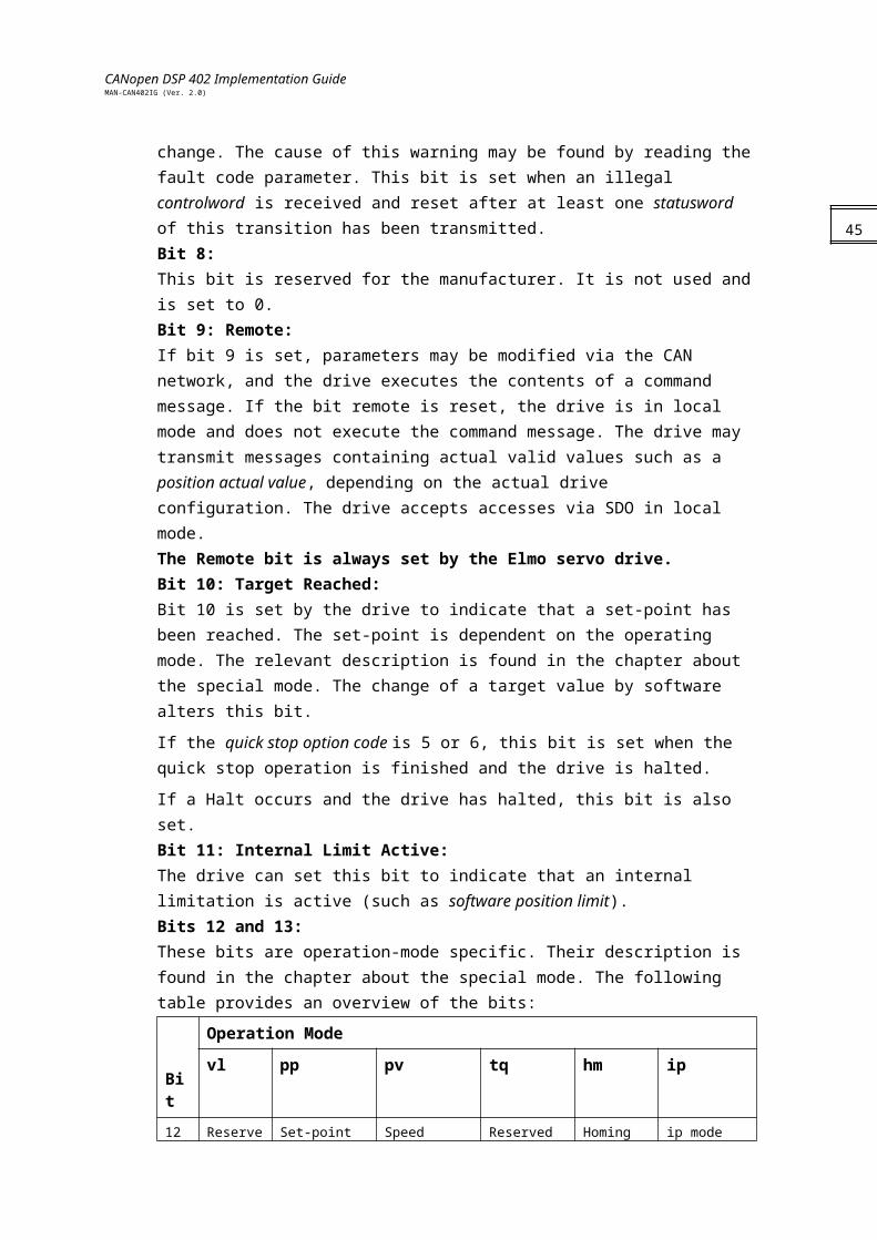
If a Halt occurs and the drive has halted, this bit is also set.Bit 11: Internal Limit Active:The drive can set this bit to indicate that an internal limitation is active (such as software position limit).Bits 12 and 13:These bits are operation-mode specific. Their description is found in the chapter about the special mode. The following table provides an overview of the bits:
Bit
Operation Mode
vl pp pv tq hm ip
33
CANopen DSP 402 Implementation GuideMAN-CAN402IG (Ver. 2.0)
12 Reserved Set-point acknowledge
Speed Reserved Homing attained
ip mode active
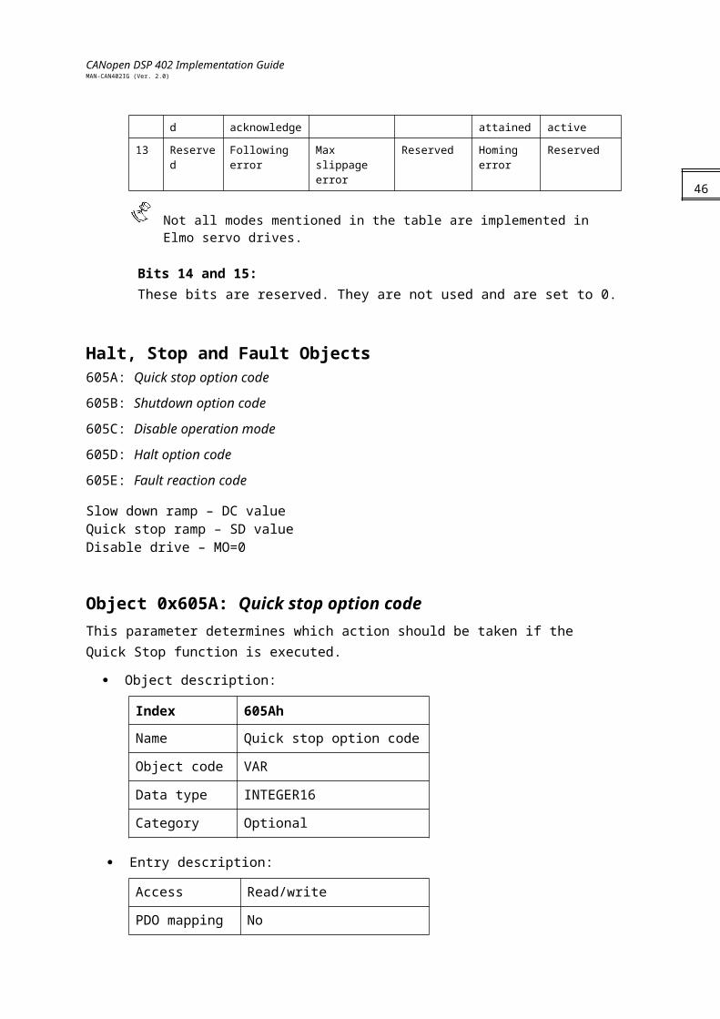
13 Reserved Following error Max slippage error
Reserved Homing error
Reserved
Not all modes mentioned in the table are implemented in Elmo servo drives.
Bits 14 and 15:These bits are reserved. They are not used and are set to 0.
Halt, Stop and Fault Objects605A: Quick stop option code
605B: Shutdown option code
605C: Disable operation mode
605D: Halt option code
605E: Fault reaction code
Slow down ramp – DC valueQuick stop ramp – SD valueDisable drive – MO=0
Object 0x605A: Quick stop option code This parameter determines which action should be taken if the Quick Stop function is executed.
Object description:
Index 605Ah
Name Quick stop option code
Object code VAR
Data type INTEGER16
Category Optional
Entry description:
Access Read/write
PDO mapping No
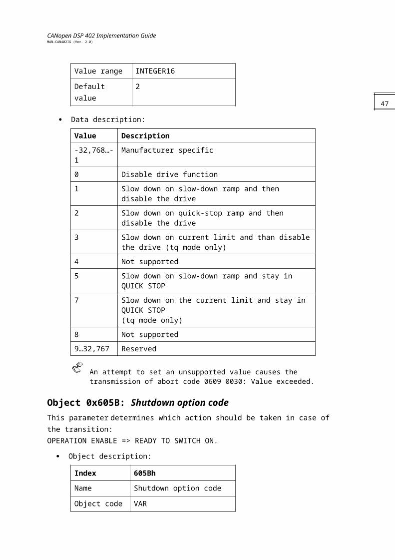
Value range INTEGER16
Default value 2
34
CANopen DSP 402 Implementation GuideMAN-CAN402IG (Ver. 2.0)
Data description:
Value Description
-32,768…-1 Manufacturer specific
0 Disable drive function
1 Slow down on slow-down ramp and then disable the drive
2 Slow down on quick-stop ramp and then disable the drive
3 Slow down on current limit and than disable the drive (tq mode only)
4 Not supported
5 Slow down on slow-down ramp and stay in QUICK STOP
7 Slow down on the current limit and stay in QUICK STOP(tq mode only)
8 Not supported
9…32,767 Reserved
An attempt to set an unsupported value causes the transmission of abort code 0609 0030: Value exceeded.
Object 0x605B: Shutdown option code This parameter determines which action should be taken in case of the transition:OPERATION ENABLE => READY TO SWITCH ON.
Object description:
Index 605Bh
Name Shutdown option code
Object code VAR
Data type INTEGER16
Category Optional
Entry description:
Access Read/write
PDO mapping No
Value range INTEGER16
Default value 0
Data description:
35

CANopen DSP 402 Implementation GuideMAN-CAN402IG (Ver. 2.0)
Value Description
-32,768…-1 Manufacturer specific
0 Disable drive function
1 Slow down on slow-down ramp; disable drive function
2…32,767 Reserved
An attempt to set an unsupported value causes the transmission of abort code 0609 0030, value exceeded.
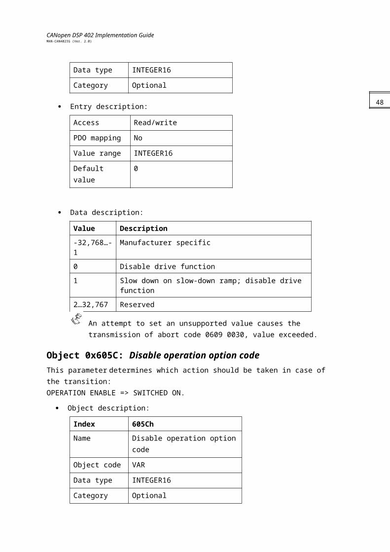
Object 0x605C: Disable operation option code This parameter determines which action should be taken in case of the transition:OPERATION ENABLE => SWITCHED ON.
Object description:
Index 605Ch
Name Disable operation option code
Object code VAR
Data type INTEGER16
Category Optional
Entry description:
Access Read/write
PDO mapping No
Value range INTEGER16
Default value 1
Data description:
Value Description
-32,768…-1 Manufacturer specific
0 Disable drive function
1 Slow down on slow-down ramp and then disable drive function
2…32,767 Reserved
An attempt to set an unsupported value causes the transmission of abort code 0609 0030: Value exceeded.
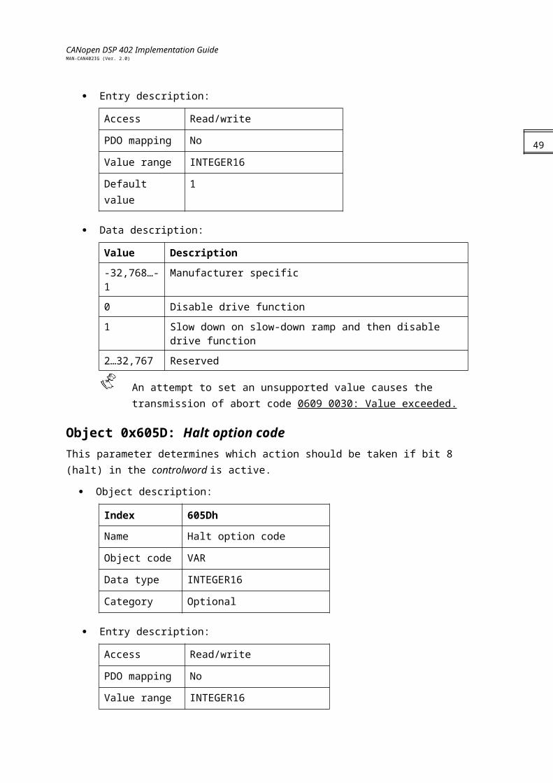
Object 0x605D: Halt option code This parameter determines which action should be taken if bit 8 (halt) in the controlword is active.
36
CANopen DSP 402 Implementation GuideMAN-CAN402IG (Ver. 2.0)
Object description:
Index 605Dh
Name Halt option code
Object code VAR
Data type INTEGER16
Category Optional
Entry description:
Access Read/write
PDO mapping No
Value range INTEGER16
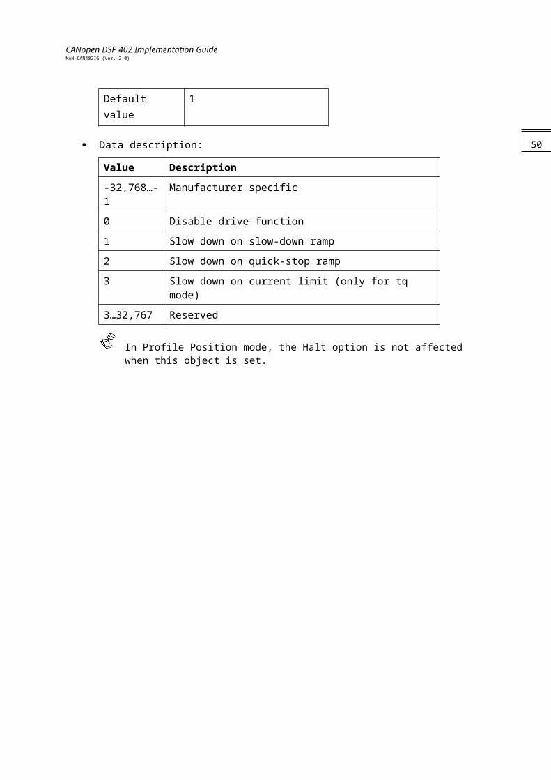
Default value 1
Data description:
Value Description
-32,768…-1 Manufacturer specific
0 Disable drive function
1 Slow down on slow-down ramp
2 Slow down on quick-stop ramp
3 Slow down on current limit (only for tq mode)
3…32,767 Reserved
In Profile Position mode, the Halt option is not affected when this object is set.
37
CANopen DSP 402 Implementation GuideMAN-CAN402IG (Ver. 2.0)
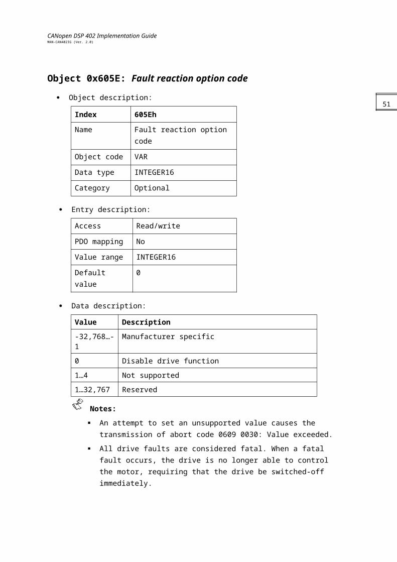
Object 0x605E: Fault reaction option code
Object description:
Index 605Eh
Name Fault reaction option code
Object code VAR
Data type INTEGER16
Category Optional
Entry description:
Access Read/write
PDO mapping No
Value range INTEGER16
Default value 0
Data description:
Value Description
-32,768…-1 Manufacturer specific
0 Disable drive function
1…4 Not supported
1…32,767 Reserved
Notes:
An attempt to set an unsupported value causes the transmission of abort code 0609 0030: Value exceeded.
All drive faults are considered fatal. When a fatal fault occurs, the drive is no longer able to control the motor, requiring that the drive be switched-off immediately.
38
CANopen DSP 402 Implementation GuideMAN-CAN402IG (Ver. 2.0)
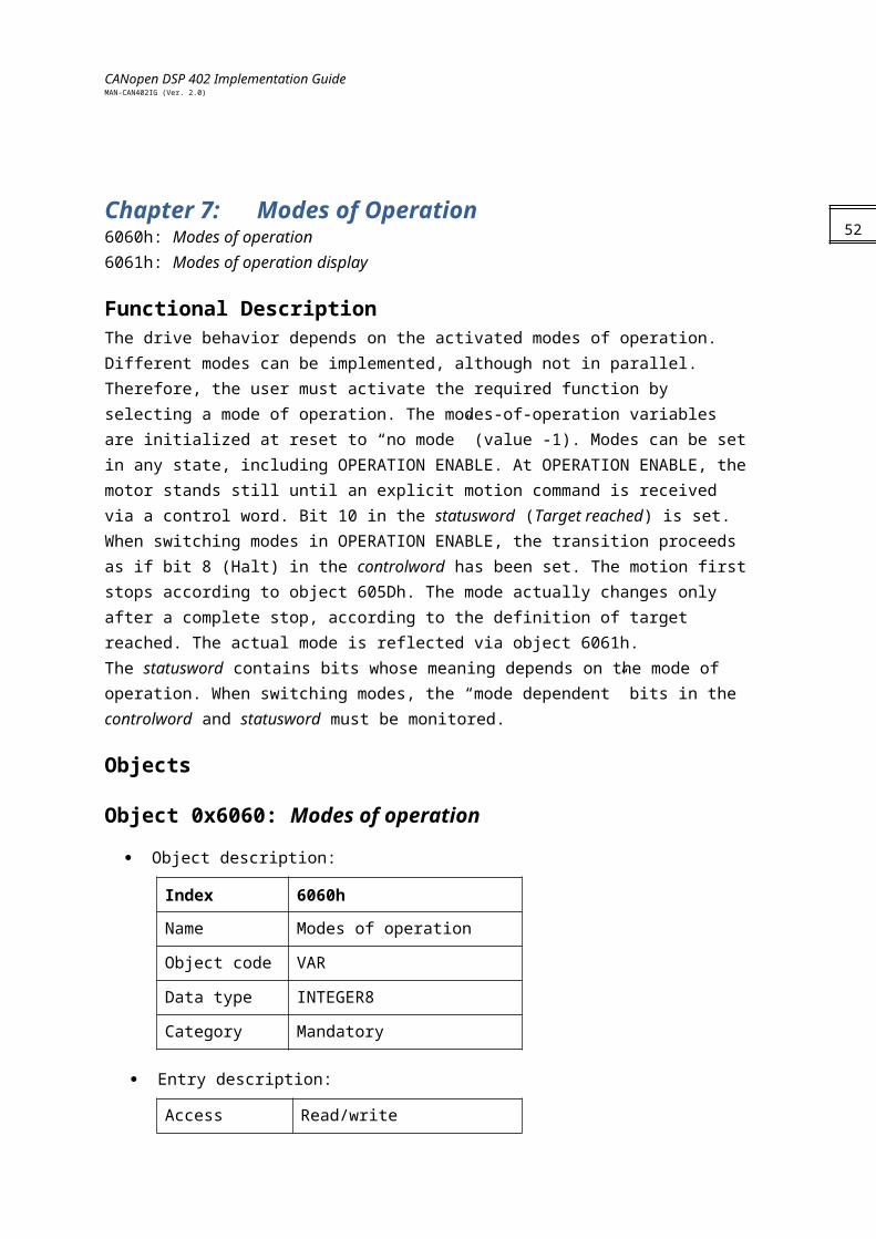
Chapter 7: Modes of Operation6060h: Modes of operation6061h: Modes of operation display
Functional DescriptionThe drive behavior depends on the activated modes of operation. Different modes can be implemented, although not in parallel. Therefore, the user must activate the required function by selecting a mode of operation. The modes-of-operation variables are initialized at reset to “no mode” (value -1). Modes can be set in any state, including OPERATION ENABLE. At OPERATION ENABLE, the motor stands still until an explicit motion command is received via a control word. Bit 10 in the statusword (Target reached) is set.When switching modes in OPERATION ENABLE, the transition proceeds as if bit 8 (Halt) in the controlword has been set. The motion first stops according to object 605Dh. The mode actually changes only after a complete stop, according to the definition of target reached. The actual mode is reflected via object 6061h.The statusword contains bits whose meaning depends on the mode of operation. When switching modes, the “mode dependent” bits in the controlword and statusword must be monitored.
Objects
Object 0x6060: Modes of operation
Object description:
Index 6060h
Name Modes of operation
Object code VAR
Data type INTEGER8
Category Mandatory
Entry description:
Access Read/write
PDO mapping No
Value range INTEGER8
Default value -1
Data description:
39
CANopen DSP 402 Implementation GuideMAN-CAN402IG (Ver. 2.0)
Value Description
-128…-2 Reserved
-3 CAN encoder mode
-1 No mode
0 Reserved
1 Profile position mode
2 Velocity (not supported)
3 Profiled velocity mode
4 Torque profiled mode
5 Reserved
6 Homing mode
7 Interpolated position mode
8…127 Reserved
40
CANopen DSP 402 Implementation GuideMAN-CAN402IG (Ver. 2.0)
Notes: A read of this object shows only the value of modes of operation. The actual mode of
the drive is reflected in the modes of operation display object. It may be changed by writing to modes of operation.
An attempt to access an unsupported mode causes the transmission of abort code 0609 0030: Value exceeded.
Object 0x6061: Modes of operation display
This object shows the current mode of operation. The meaning of the returned value corresponds to that of the modes of operation option code (index 6060h).
Object description:
Index 6061h
Name Modes of operation display
Object code VAR
Data type INTEGER8
Category Mandatory
Entry description:
Access Read only
PDO mapping No
Value range INTEGER8
Default value -1
Data description:Similar to object 6060h, modes of operation.
The actual mode is reflected in the modes of operation display (index 6061h), and not in modes of operation (index 6060h).
41
CANopen DSP 402 Implementation GuideMAN-CAN402IG (Ver. 2.0)
Chapter 8: Factors607Eh: Polarity
6089h: Position notation index
608Ah: Position dimension index
608Bh: Velocity notation index
608Ch: Velocity dimension index
608Dh: Acceleration notation index
608Eh: Acceleration dimension index
608Fh: Position encoder resolution
6090h: Velocity encoder resolution
6093h: Position factor
6094h: Velocity encoder factor
6095h: Velocity factor 1
6096h: Velocity factor 2
6097h: Acceleration factor
Physical dimensions and sizes need to be converted into the device internal units, requiring a number of different factors. This chapter describes how these factors influence the system, how they are calculated and which data is needed to build them.
Relationship between Physical and Internal UnitsThe factors defined in the factor group determine a relationship between the Elmo drive internal units and the application physical units. The factors are a result of the calculation of two parameters – called dimension index and notation index – which are defined Appendix A and Appendix B. One parameter indicates the physical dimensions, and the other indicates the decimal exponent for the values. These factors are directly used to normalize the physical values.The application-specific parameters are used in the corresponding mode of operation to build the described factors. Parameters that are commonly used are integrated in the object dictionary without defining their junctions. This guarantees a common parameter number for further use without the need for predefinition.
Functions and Limits Factors cannot be set while the drive is in OPERATION ENABLE state.
Divisors cannot be set to 0. An abort message with abort code 0609 0030 will be transmitted.
Values are truncated to the nearest integer.
42

CANopen DSP 402 Implementation GuideMAN-CAN402IG (Ver. 2.0)
Objects
Object 0x607E: Polarity Position demand value and position actual value are multiplied by 1 or -1, depending on the value of the polarity flag.
Object description:
Index 607Eh
Name Polarity
Object code VAR
Data type UNSIGNED8
Category Optional
Entry description:
Access Read/write
PDO mapping Yes
Value range UNSIGNED8
Default value 0
Data Description
7 6 5 . . . 0
Position polarity
Velocity polarity
Reserved
Value Description
0 Multiply by 1
1 Multiply by -1
43
CANopen DSP 402 Implementation GuideMAN-CAN402IG (Ver. 2.0)
Object 0x6089: Position notation indexThis index is used to scale position objects. The unit is defined by the physical dimensions and calculated by unit type and exponent, declared in the dimension/ notation index tables (refer to Appendix A and Appendix B).
Notes:
The Elmo drive does not use this object; it is available for user convenience.
The object is not checked for value and consistency.
Object description:
Index 6089h
Name Position notation index
Object code VAR
Data type INTEGER8
Category Optional
Entry description:
Access Read/write
PDO mapping Yes
Value range INTEGER8
Default value 0
Object 0x608A: Position dimension indexThis object defines the position dimension index, which is used together with the position notation index (object 0x6089) to define a unit (refer to Appendix A).
Notes:
The Elmo drive does not use this object; it is available for user convenience.
The object is not checked for value and consistency.
This object is non-volatile.
Object description:
Index 608Ah
Name Position dimension index
Object code VAR
Data type UNSIGNED8
44
CANopen DSP 402 Implementation GuideMAN-CAN402IG (Ver. 2.0)
Category Optional
45
CANopen DSP 402 Implementation GuideMAN-CAN402IG (Ver. 2.0)
Entry description:
Access Read/write
PDO mapping No
Value range UNSIGNED8
Default value —
Object 0x608B: Velocity notation index This object defines the velocity notation index. The unit is defined by the physical dimensions and calculated by unit type and exponent, declared in the dimension/ notation index tables (refer to Appendix A and Appendix B).
Notes:
The Elmo drive does not use this object; it is available for user convenience.
The object is not checked for value and consistency.
This object is non-volatile.
Object description:
Index 608Bh
Name Velocity notation index
Object code VAR
Data type INTEGER8
Category Optional
Entry description:
Access Read/write
PDO mapping No
Value range INTEGER8
Default value —
46
CANopen DSP 402 Implementation GuideMAN-CAN402IG (Ver. 2.0)
Object 0x608C: Velocity dimension indexThis object defines the velocity dimension index, which is used together with the velocity notation index (object 0x608B) to define a unit (refer to Appendix A and Appendix B).
Notes:
The Elmo drive does not use this object; it is available for user convenience.
The object is not checked for value and consistency. This object is non-volatile.
Object description:
Index 608Ch
Name Velocity dimension index
Object code VAR
Data type UNSIGNED8
Category Optional
Entry description:
Access Read/write
PDO mapping No
Value range UNSIGNED8
Default value —
Object 0x608D: Acceleration notation indexThis object defines the acceleration notation index. The unit is defined by the physical dimensions and calculated by unit type and exponent, declared in the dimension / notation index tables (refer to Appendix A and Appendix B).
Notes:
The Elmo drive does not use this object; it is available for user convenience.
The object is not checked for value and consistency. This object is non-volatile.
Object description:
Index 608Dh
Name Acceleration notation index
Object code VAR
Data type INTEGER8
Category Optional
47
CANopen DSP 402 Implementation GuideMAN-CAN402IG (Ver. 2.0)
48
CANopen DSP 402 Implementation GuideMAN-CAN402IG (Ver. 2.0)
Entry description:
Access Read/write
PDO mapping No
Value range INTEGER8
Default value —
Object 0x608E: Acceleration dimension index This object defines the acceleration dimension index, which is used together with the acceleration notation index (object 0x608D) to define a unit (refer to Appendix A).
Notes:
The Elmo drive does not use this object; it is available for user convenience.
The object is not checked for value and consistency.
This object is non-volatile.
Object description:
Index 608Eh
Name Acceleration dimension index
Object code VAR
Data type UNSIGNED8
Category Optional
Entry description:
Access Read/write
PDO mapping No
Value range UNSIGNED8
Default value —
49
CANopen DSP 402 Implementation GuideMAN-CAN402IG (Ver. 2.0)
Object 0x608F: Position encoder resolution This object defines the ratio of encoder increments per motor revolution:
=
Object description:
Index 608Fh
Name Position encoder resolution
Object code ARRAY
Data type UNSIGNED32
Category Optional
Entry description:
Sub-index 0
Description Number of entries
Entry category Mandatory
Access Read only
PDO mapping No
Value range 2
Default value 2
Sub-index 1
Description Encoder increments
Entry category Optional
Access Read/write
PDO mapping No
Value range UNSIGNED32
Default value 1
Sub-index 2
Description Motor revolutions
Entry category Optional
Access Read/write
PDO mapping No
Value range UNSIGNED32
50
CANopen DSP 402 Implementation GuideMAN-CAN402IG (Ver. 2.0)
Default value 1
Object 0x6090: Velocity encoder resolution This object defines the ratio of encoder increments/second per motor revolutions/ second.
=
Object description:
Index 6090h
Name Velocity encoder resolution
Object code ARRAY
Data type UNSIGNED32
Category Optional
Entry description:
Sub-index 0
Description Number of entries
Entry category Mandatory
Access Read only
PDO mapping No
Value range 2
Default value 2
Sub-index 1
Description Encoder increments per second
Entry category Mandatory
Access Read/write
PDO mapping No
Value range UNSIGNED32
Default value 1
Sub-index 2
Description Motor revolutions per second
Entry category Mandatory
Access Read/write
51
CANopen DSP 402 Implementation GuideMAN-CAN402IG (Ver. 2.0)
PDO mapping No
Value range UNSIGNED32
Default value 1
Object 0x6093: Position factor This object converts the desired position (in position units) into the internal format (in increments). The object entries are the numerator and the divisor.
Object description:
Index 6093h
Name Position factor
Object code ARRAY
Data type UNSIGNED32
Category Optional
Entry description:
Sub-index 0
Description Number of entries
Entry category Mandatory
Access Read only
PDO mapping No
Value range 2
Default value 2
Sub-index 1
Description Numerator
Entry category Mandatory
Access Read/write
PDO mapping No
Value range UNSIGNED32
Default value 1
Sub-index 2
Description Divisor
Entry category Mandatory
Access Read/write
52
CANopen DSP 402 Implementation GuideMAN-CAN402IG (Ver. 2.0)
PDO mapping No
Value range UNSIGNED32
Default value 153
CANopen DSP 402 Implementation GuideMAN-CAN402IG (Ver. 2.0)
Notes:
The position factor is calculated according to this object regardless of the setting of any other objects, such as 0x608F (position encoder resolution).
The actual value range of the divisor may not exceed 16,383 due to numeric overflow.
Object 0x6094: Velocity encoder factor This object converts the desired velocity (in velocity units) into the internal format (in increments/second).
Object description:
Index 6094h
Name Velocity encoder factor
Object code ARRAY
Data type UNSIGNED32
Category Optional
Entry description:
Sub-index 0
Description Number of entries
Entry category Mandatory
Access Read only
PDO mapping No
Value range 2
Default value 2
Sub-index 1
Description Numerator
Entry category Mandatory
Access Read/write
PDO mapping No
Value range UNSIGNED32
Default value 1
54
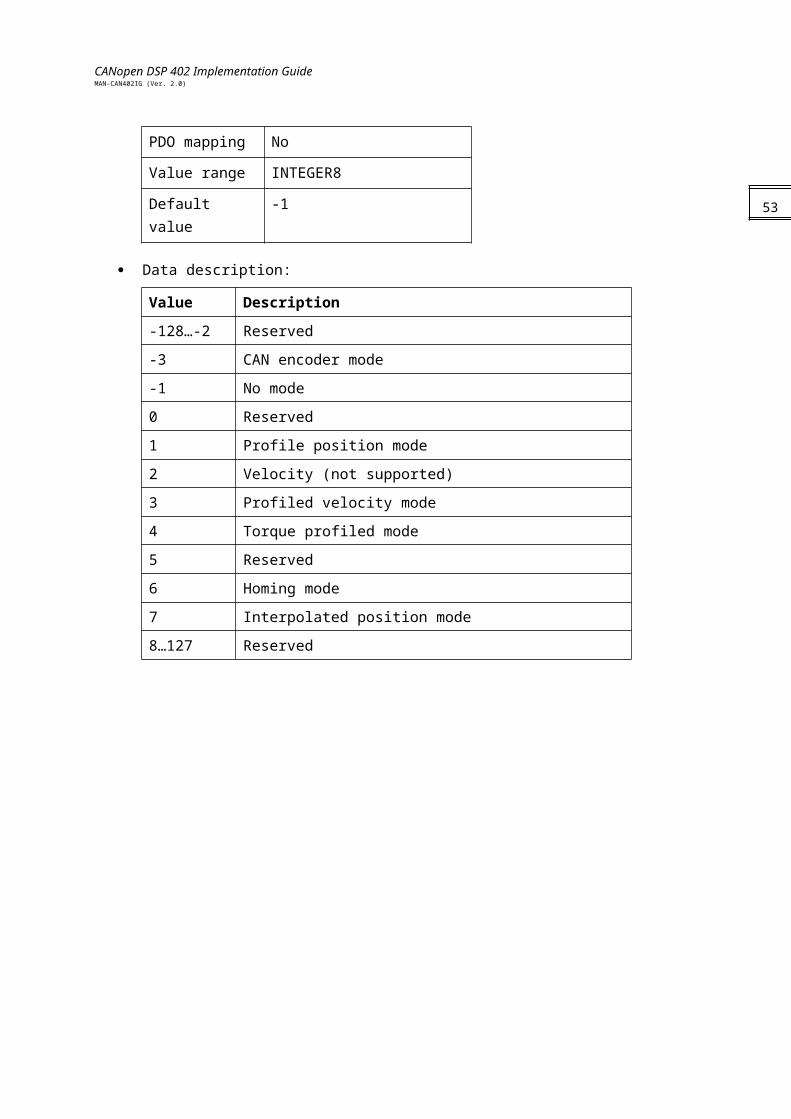
CANopen DSP 402 Implementation GuideMAN-CAN402IG (Ver. 2.0)
Sub-index 2
Description Divisor
Entry category Optional
Access Read/write
PDO mapping No
Value range UNSIGNED32
Default value 1
Notes:
The position factor is calculated according to this object regardless of the setting of any other objects, such as 0x6090 (velocity encoder resolution).
The actual value range of the divisor may not exceed 16,383 due to numeric overflow.
Object 0x6095: Velocity factor 1 This object is used to convert motor data (such as maximum motor revolutions) into velocity data (such as maximum velocity) because the data items are based on different physical dimensions.
Object description:
Index 6095h
Name Velocity factor 1
Object code ARRAY
Data type UNSIGNED32
Category Optional
Entry description:
Sub-index 0
Description Number of entries
Entry category Mandatory
Access Read only
PDO mapping No
Value range 2
Default value 2
55
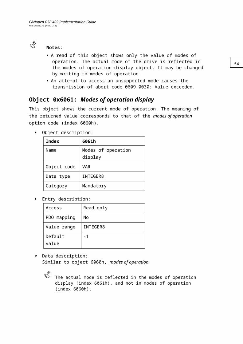
CANopen DSP 402 Implementation GuideMAN-CAN402IG (Ver. 2.0)
Sub-index 1
Description Numerator
Entry category Optional
Access Read/write
PDO mapping No
Value range UNSIGNED32
Default value 1
Sub-index 2
Description Divisor
Entry category Optional
Access Read/write
PDO mapping No
Value range UNSIGNED32
Default value 1
Notes:
The velocity factor 1 is calculated according to this object regardless of the setting of any other objects, such as 0x6092 (feed constant).
The actual value range of the divisor may not exceed 16,383 due to numeric overflow.
Object 0x6096: Velocity factor 2 This object is used to define the relationship between the velocity encoder data and the position encoder data, because they are based on different dimensions.
Object description:
Index 6096h
Name Velocity factor 2
Object code ARRAY
Data type UNSIGNED32
Category Optional
56
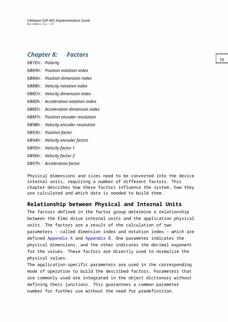
CANopen DSP 402 Implementation GuideMAN-CAN402IG (Ver. 2.0)
Entry description:
Sub-index 0
Description Number of entries
Entry category Mandatory
Access Read only
PDO mapping No
Value range 2
Default value 2
Sub-index 1
Description Numerator
Entry category Optional
Access Read/write
PDO mapping No
Value range UNSIGNED32
Default value 1
Sub-index 2
Description Divisor
Entry category Optional
Access Read/write
PDO mapping No
Value range UNSIGNED32
Default value 1
Notes:
The velocity factor 2 is calculated according to this object regardless of the setting of any other objects, such as 0x608F (position encoder resolution).
The actual value range of the divisor may not exceed 16,383 due to numeric overflow.
57

CANopen DSP 402 Implementation GuideMAN-CAN402IG (Ver. 2.0)
Object 0x6097: Acceleration factor This object converts the acceleration (in acceleration units/second2) into the internal format (in increments/second2).
Object description:
Index 6097h
Name Acceleration factor
Object code ARRAY
Data type UNSIGNED32
Category Optional
Entry description:
Sub-index 0
Description Number of entries
Entry category Mandatory
Access Read only
PDO mapping No
Value range 2
Default value 2
Sub-index 1
Description Numerator
Entry category Mandatory
Access Read/write
PDO mapping No
Value range UNSIGNED32
Default value 1
Sub-index 2
Description Divisor
Entry category Mandatory
Access Read/write
PDO mapping No
Value range UNSIGNED32
Default value 1
58
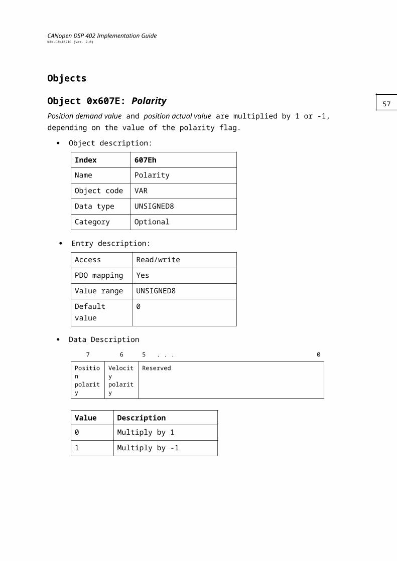
CANopen DSP 402 Implementation GuideMAN-CAN402IG (Ver. 2.0)
Notes:
The acceleration factor is calculated according to this object regardless of the setting of any other objects, such as 0x6094 (velocity encoder factor).
The actual value range of the divisor may not exceed 16,383 due to numeric overflow.
59
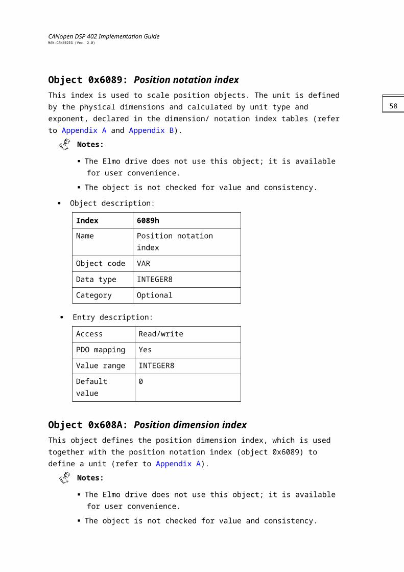
CANopen DSP 402 Implementation GuideMAN-CAN402IG (Ver. 2.0)
Chapter 9: Homing607Ch: Home offset
6098h: Homing method
6099h: Homing speeds
609Ah: Homing acceleration
General InformationThis chapter describes the method by which a drive seeks the home position (also called the datum, reference point or zero point). Homing can be performed using limit switches at the ends of travel or a home switch (zero point switch) in mid-travel; most of the methods also use the index (zero) pulse train from an incremental encoder.Input DataThe user can specify the speeds, acceleration and method of homing. An additional object, home offset, is used to displace zero in the user’s coordinate system from the home position. There are two homing speeds: in a typical cycle the faster speed is used to find the home switch and the slower speed is used to find the index pulse. Output DataThere is no output data except for those bits in the statusword that return the status or result of the homing process and the demand to the position control loops.Internal StatesThe homing mode is controlled by the bits of the controlword and statusword.Homing Mode Controlword
Bit Function
0…3 Described in Device Control
4 Home operation start
5..6 Reserved
7 Described in Device Control
8 Halt
9..12 Described in Device Control
13..15 Described in Device Control
60
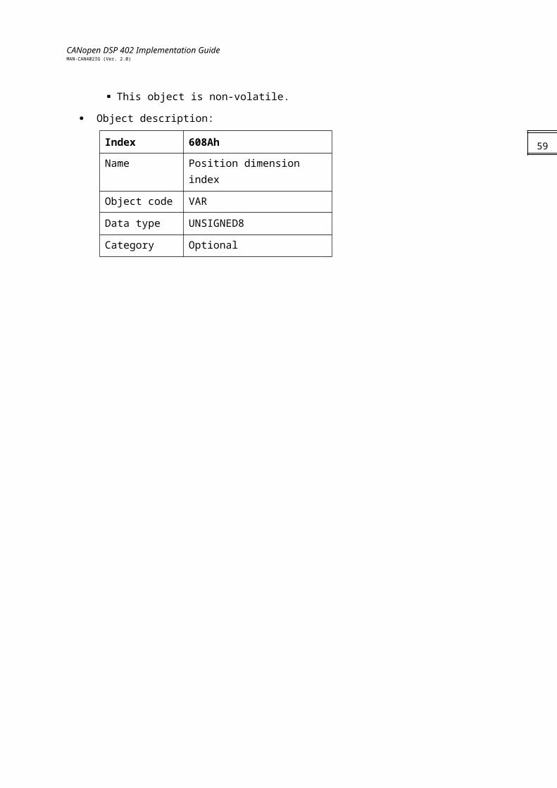
CANopen DSP 402 Implementation GuideMAN-CAN402IG (Ver. 2.0)
Name Value Description
Homing operation start
0 Homing mode inactive.
0→1 Start homing mode.
1 Homing mode active.
1→0 Interrupt homing mode.
Halt 0 Execute the instruction of bit 4.
1 Stop axle with homing deceleration.
Notes:
If homing is interrupted by setting bit 4 from “1” to “0”, the movement of the motor is not interrupted; that is, the motor remains in its present state, either moving or not. The home sequence is interrupted and the home target is not attained. By setting the bit back to “1”, the homing mode begins again.
If a Halt occurs, the drive stops the homing method and halts the motor according to object 609Ah. When this bit is set to “0” and bit 4 remains “1”, the home method begins again.
Statusword of Homing Mode
Bit Function
0…9 Described in Device Control
10 Target reached
11 Described in Device Control
12 Homing attained
13 Homing error
14…15 Described in Device Control
Name Value Description
Target reached 0 Halt = 0: Homing position not reachedHalt = 1: Axle decelerates
1 Halt = 0: Homing position reachedHalt = 1: Velocity of axle is 0
Homing attained 0 Homing mode not yet completed.
1 Homing mode carried out successfully.
Homing error 0 No homing error.
1 Homing error occurred.Homing mode carried out unsuccessfully.Error cause found in error code.
61
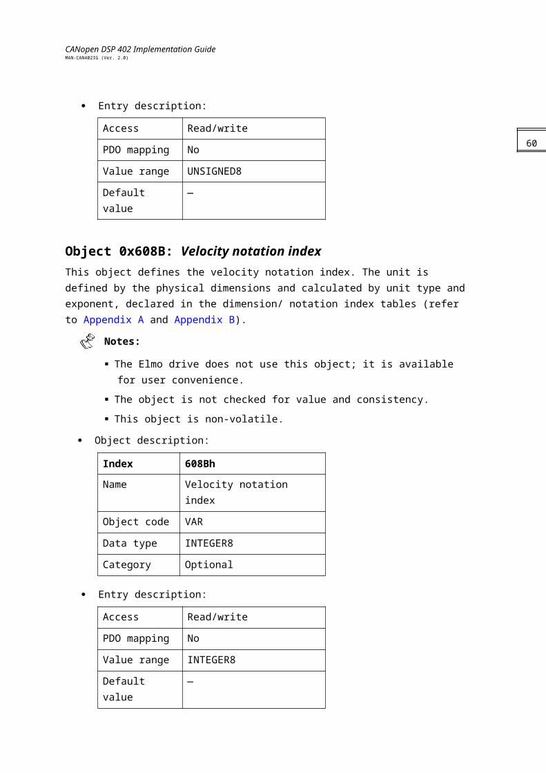
CANopen DSP 402 Implementation GuideMAN-CAN402IG (Ver. 2.0)
During the homing process, no reference position limits are active. If no physical limit
exists — such as the limit switch — the load may travel indefinitely.
Objects
Object 0x607C: Home offset This object is the difference between the zero position for the application and the machine home position (found during homing), measured in position units. During homing, the machine home position is found. Once homing is completed, the zero position is offset from the home position by adding the home offset to the home position. All subsequent absolute moves are taken relative to this new zero position, as illustrated in the following diagram.
By default, the home offset is 0.
Object description:
Index 607Ch
Name Home offset
Object code VAR
Data type INTEGER32
Category Optional
Entry description:
Access Read/write
PDO mapping No
Value range INTEGER32
Default value No
The zero position is determined after a successful homing sequence (home attain).
Internal position limits are taken relative to the zero position point.
62
home_offset
ZeroPosition
HomePosition
home_offset
ZeroPosition
HomePosition

CANopen DSP 402 Implementation GuideMAN-CAN402IG (Ver. 2.0)
Object 0x6098: Homing method This object determines the method used during homing.
Object description:
Index 6098h
Name Homing method
Object code VAR
Data type INTEGER8
Category Mandatory
Entry description:
Access Read/write
PDO mapping No
Value range INTEGER8
Default value 0
Data description:
Value Description
-128…-1 Manufacturer specific
0 No homing operation required
1…35 Methods 1 to 35 (see Functional Description)
36…127 Reserved
63
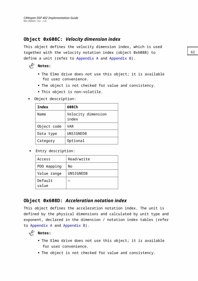
CANopen DSP 402 Implementation GuideMAN-CAN402IG (Ver. 2.0)
Object 0x6099: Homing speeds This entry in the object dictionary defines the speeds used during homing, in velocity units. The value is normalized to increments by velocity code factor. Typically, a high speed is used when searching for a home switch and the slow speed is used when searching for the index.
Object description:
Index 6099h
Name Homing speeds
Object code ARRAY
Data type UNSIGNED32
Category Mandatory
Entry description:
Sub-index 0
Description Number of entries
Entry category Mandatory
Access Read only
PDO mapping No
Value range 2
Default value 2
Sub-index 1
Description Speed during search for switch
Entry category Mandatory
Access Read/write
PDO mapping No
Value range UNSIGNED32
Default value 0
Sub-index 2
Description Speed during search for zero
Entry category Mandatory
Access Read/write
PDO mapping No
Value range UNSIGNED32
64
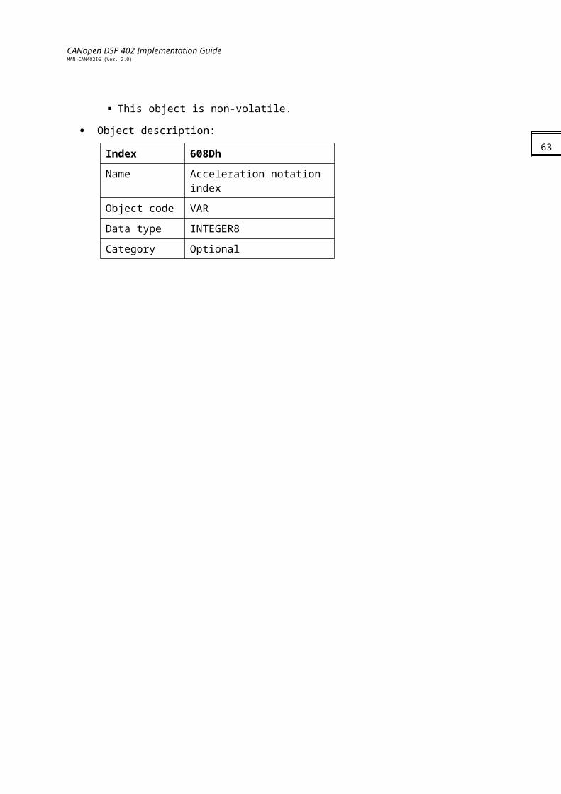
CANopen DSP 402 Implementation GuideMAN-CAN402IG (Ver. 2.0)
Default value 0
The speed is submitted to the maximum speed limit given by the user during setup.
Otherwise, an abort message with abort code 0609 0030, “Value range of parameter exceeded” is activated. If the limits have been changed during the process, the drive enters a fault state.
Object 0x609A: Homing acceleration This object establishes the acceleration to be used for all accelerations and decelerations with the standard homing modes, and is given in acceleration units.
Object description:
Index 609Ah
Name Homing acceleration
Object code VAR
Data type UNSIGNED32
Category Optional
Entry description:
Access Read/write
PDO mapping No
Value range UNSIGNED32
Default value No
Home deceleration is performed according to the SD value set during setup. The user
may use the binary interpreter to modify this value. Refer to the relevant Command Reference Manual for the SD parameter information.
Functional DescriptionChoosing a method of homing by writing a value to homing method clearly establishes the:
Homing signal (positive limit switch, negative limit switch, home switch)
Direction of actuation
Position of the index pulse, where appropriateHoming is performed on either the main position sensor (PX) or the auxiliary position sensor (PY), depending on the unit mode — for position loop (UM=5) or dual loop (UM=4) — respectively. The relevant source is selected when homing is activated by the controlword.The home position and zero position are offset by the home offset (see the home offset definition for how this offset is used).
65
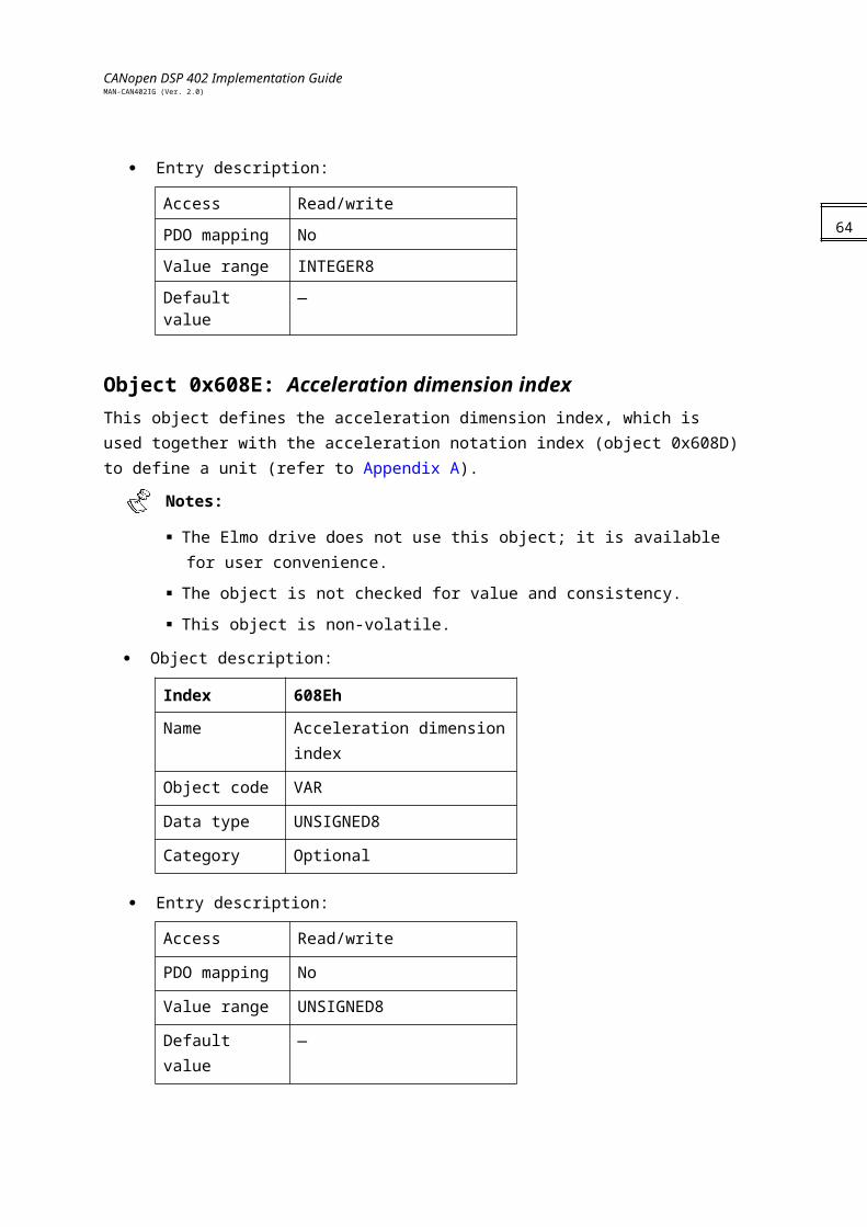
CANopen DSP 402 Implementation GuideMAN-CAN402IG (Ver. 2.0)
Various homing positions are illustrated in the diagrams that follow (section ). A circled number indicates the code for selecting the homing position. The direction of movement is also indicated.
Additional homing methods are available with other modes of the Elmo drives, such as
the binary interpreter or the user program.Four sources of homing signal are available: the negative and positive limit switches, the home switch and, and the index pulse, which are handled by fast inputs. The captured value is independent of drive sampling time. Limit switches must be previously defined during the drive setup (using the IL[N] command).In the homing sequence diagrams, the encoder count increases as the axle position moves to the right. In other words, the left is the minimum position and the right is the maximum position. In the SimplIQ drive, the user may select the configuration; otherwise, it is determined according to the setup process.Error CasesError cases are events in which the drive cannot reach the home method or operate the home demand parameters, such as high speed. In cases where the limit is known in advance — such as home speed higher than the speed limit — an abort message is executed. In cases where a fault is hit during the operation of the home procedure — such as an abort switch — the drive goes into a fault state. The homing error bit in the statusword is set and an emergency message for motor fault, if not masked, is transmitted. The error register can be monitored for the fault indication. In cases where a limit prevents the home sequence from being finished, such as reaching a mechanical limit, no special indication is given. It is up to the application to monitor or set a timeout sequence for the home procedure.
66
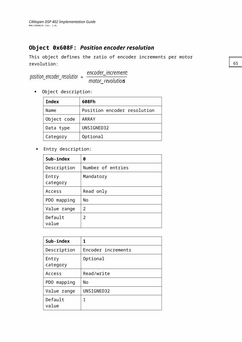
CANopen DSP 402 Implementation GuideMAN-CAN402IG (Ver. 2.0)
DSP 402 Homing MethodsThe following sub-sections describe the details of how each homing mode functions. The Elmo drives support each of these methods.
Method 1: Homing on the negative limit switch and index pulse
Using this method, the initial direction of movement is leftward if the negative limit switch is inactive (here shown as low). The home position is at the first index pulse to the right of the position where the negative limit switch becomes inactive.
Figure 9-4: Homing on the negative limit switch and index pulse
Method 2: Homing on the positive limit switch and index pulseUsing this method, the initial direction of movement is rightward if the positive limit switch is inactive (here shown as low). The position of home is at the first index pulse to the left of the position where the positive limit switch becomes inactive.
Figure 9-5: Homing on the positive limit switch and index pulse
67
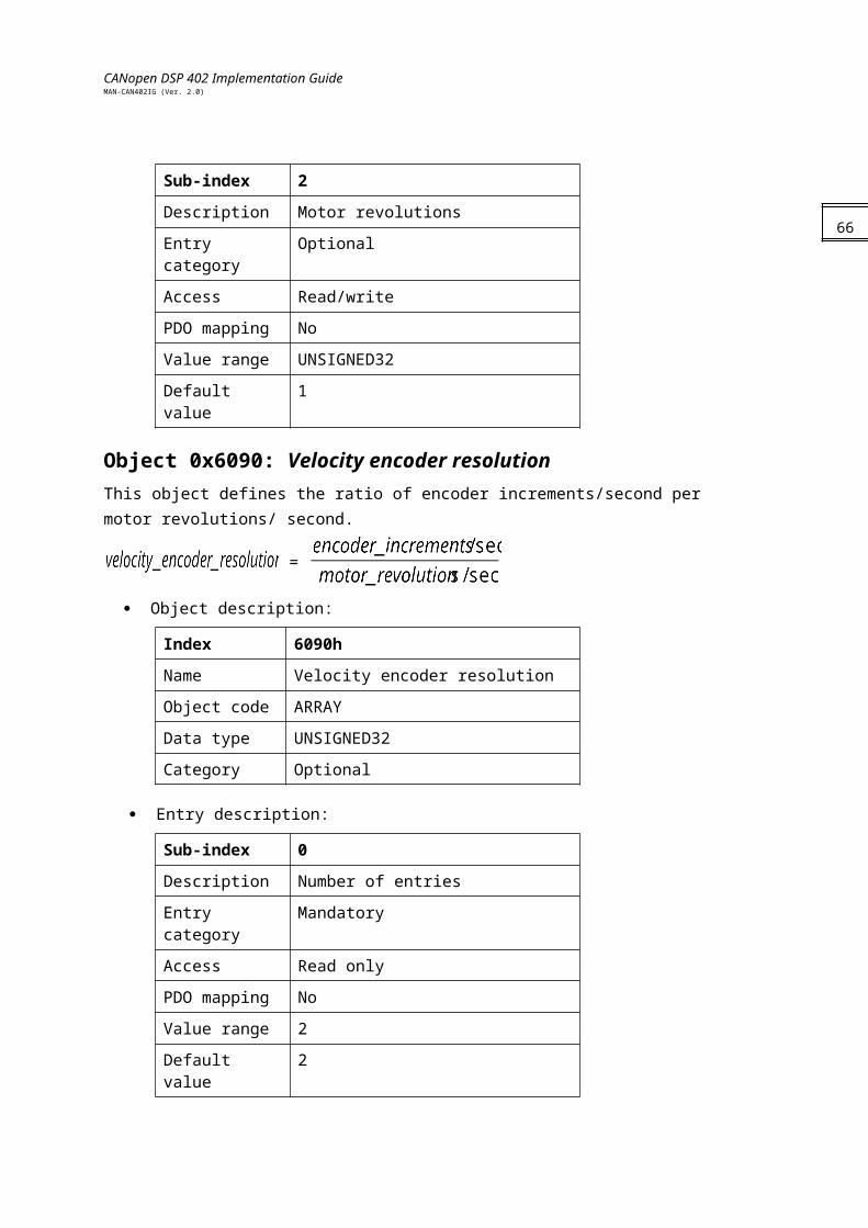
CANopen DSP 402 Implementation GuideMAN-CAN402IG (Ver. 2.0)
Methods 3 and 4: Homing on the positive home switch and index pulse
Using methods 3 or 4, the initial direction of movement is dependent on the state of the home switch. The home position is at the index pulse to either the left or right of the pint where the home switch changes state. If the initial position is sited so that the direction of movement must reverse during homing, the point at which the reversal takes place is anywhere after a change of state of the home switch.
Figure 9-6: Homing on the positive home switch and index pulse
Methods 5 and 6: Homing on the negative home switch and index pulse
Using methods 5 or 6, the initial direction of movement is dependent on the state of the home switch. The home position is at the index pulse to either the left or the right of the point where the home switch changes state. If the initial position is sited so that the direction of movement must reverse during homing, the point at which the reversal takes place is anywhere after a change of state of the home switch.
Figure 9-7: Homing on the negative home switch and index pulse
68
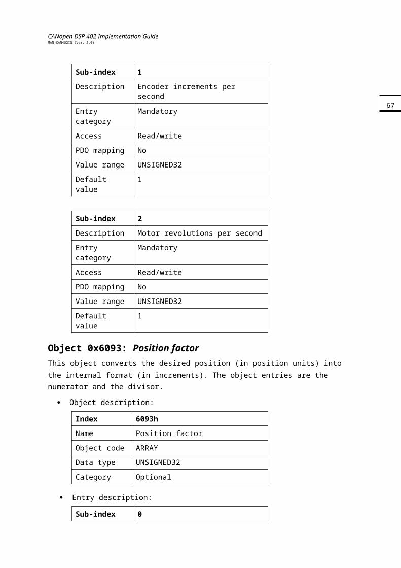
CANopen DSP 402 Implementation GuideMAN-CAN402IG (Ver. 2.0)
Methods 7 to 14: Homing on the home switch and index pulseThese methods use a home switch that is active over only a portion of the travel; in effect, the switch has a “momentary” action as the axle position sweeps past the switch.Using methods 7 to 10, the initial direction of movement is to the right, and using methods 11 to 14, the initial direction of movement is to the left, except if the home switch is active at the start of motion. In this case, the initial direction of motion is dependent on the edge being sought. The home position is at the index pulse on either side of the rising or falling edges of the home switch, as shown in the following two diagrams. If the initial direction of movement leads away from the home switch, the drive must reverse on encountering the relevant limit switch.
Figure 9-8: Homing on the home switch and index pulse — positive initial move
Figure 9-9: Homing on the home switch and index pulse — negative initial move
Methods 15 and 16: ReservedThese methods are reserved for future expansion of the homing mode.
69
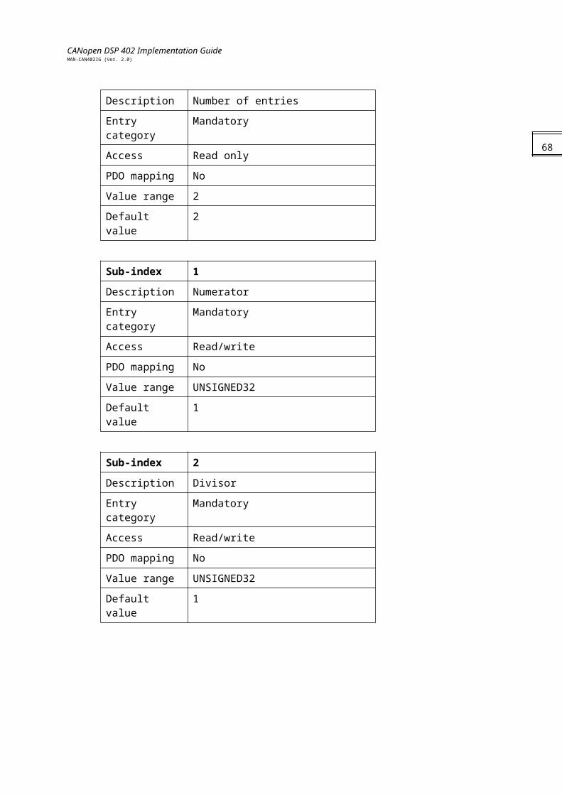
CANopen DSP 402 Implementation GuideMAN-CAN402IG (Ver. 2.0)
Methods 17 to 30: Homing without an index pulseThese methods are similar to methods 1 to 14, except that the home position is not dependent on the index pulse; it is dependent only on the relevant home or limit switch transitions. For example, methods 19 and 20 are similar to methods 3 and 4, as shown in the following diagram:
Figure 9-10: Homing on the positive home switch
Methods 31 and 32: ReservedThese methods are reserved for future expansion of the homing mode.
Methods 33 and 34: Homing on the index pulseUsing methods 33 or 34, the direction of homing is negative or positive, respectively. The home position is at the index pulse found in the selected direction.
Figure 9-11: Homing on the positive home switch
Method 35: Homing on the current positionIn this method, the current position is taken to be the home position.
70
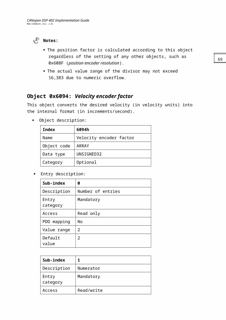
CANopen DSP 402 Implementation GuideMAN-CAN402IG (Ver. 2.0)
Chapter 10: Position Control Function6062h: Position demand value in position units
6063h: Position actual value in increments
6064h: Position actual value
6065h: Following error window
6067h: Position window
6068h: Position window time out
60F4h: Following error actual value
60FAh: Position control effort
60FCh: Position demand value in increments
General InformationThis chapter describes all parameters required for closed-loop position control. The control loop is fed with the position demand value as one of the outputs of the trajectory generator and with the output of the position detection unit (position actual value) as input parameters. The behavior of the control is influenced by the control parameters. Position control parameters (PI/P) may be set using the Composer Wizard during setup.To ensure that the physical limits of a drive are not exceeded, an absolute limit function is implemented for the position control effort. The Elmo drive implements a cascaded control loop in which the position control effort is a velocity demand value for the velocity control loop. For further information about tuning the position loop and using the Composer Wizard, refer to the SimplIQ Composer User Manual and the SimplIQ Software Manual.
The following terms are used in this chapter:
Following error:A position actual value outside the allowed range of the following error window around a position demand value for longer than the following error timeout results in setting bit 13, following error, in the statusword.
The position following error calculates each cycle of the position control. The position
demand value must be set lower than the setup value of the drive following error ER[3]. When the position following error exceeds ER[3], the motion aborts.
Position reached:This function provides the option of defining a position range around a position demand value to be regarded as valid. If a drive position is within this area for a specified time — the position window time — the related control bit 10 target reached in the statusword is set. Bit 10 is reset to 0 when the motor is off.
The position range in the Elmo servo drive is limited to 1 * 109 regardless of the
DSP 402 maximum range.
71
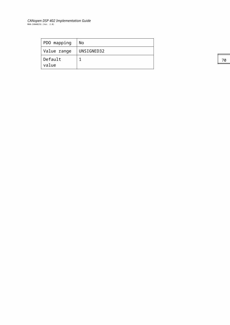
CANopen DSP 402 Implementation GuideMAN-CAN402IG (Ver. 2.0)
Objects
Object 0x6062: Position demand value The value of this object is taken from the internal position command and is given in position units after being converted by position factor.
Object description:
Index 6062h
Name Position demand value
Object code VAR
Data type INTEGER32
Category Optional
Entry description:
Access Read only
PDO mapping Yes
Value range INTEGER32
Default value 0
Object 0x6063: Position actual value The actual value of the position measurement device is one of the two input values of the closed loop position control. The data unit is defined as increments.
Object description:
Index 6063h
Name Position actual value - increments
Object code VAR
Data type INTEGER32
Category Mandatory
Entry description:
Access Read only
PDO mapping Yes
Value range INTEGER32
Default value 0
Notes:
Value range submits to the position range limits as defined in the specific drive. For the Harmonica servo drive: 1 * 109
72
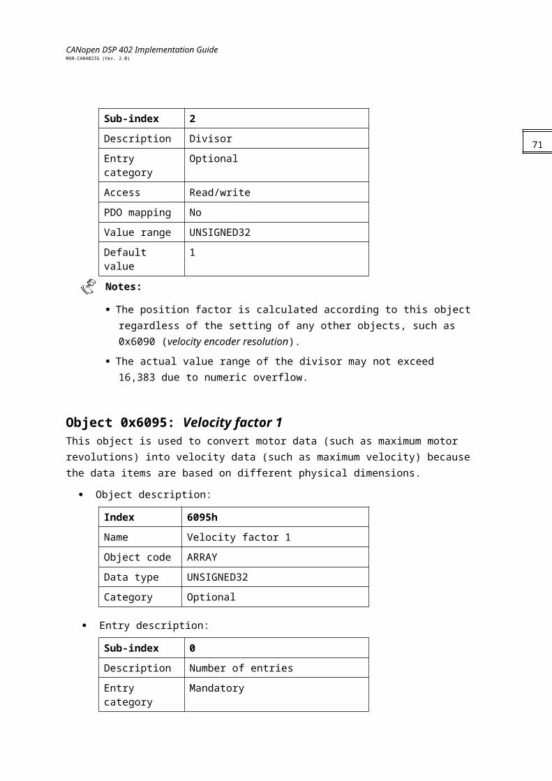
CANopen DSP 402 Implementation GuideMAN-CAN402IG (Ver. 2.0)
This object has a write access when the motor is not enabled.
Object 0x6064: Position actual valueThis object represents the actual value of the position measurement device, in user-defined units. When dual loop mode is active (UM=4), this object returns the value of the position sensor as derived from the load feedback (PY command); in all single loop modes (UM = 1,2,3,5), it returns the motor position feedback (PX command) value.
Object description:Index 6064H
Name Position actual value
Object code VAR
Data type INTEGER32
Category Optional
Entry description:
Access Read only
PDO mapping Yes
Value range INTEGER32
Default value 0
Object 0x6065: Following error window This object defines a range of tolerated position values symmetrical to the position demand value. Because it is usually used with user-defined units, a transformation into increments with the position factor is necessary. If the position actual value is out of the following error window, a following error occurs. A following error may occur:
When a drive is blocked
When the profile velocity is unreachable
Due to wrong closed loop coefficientsIf the value of the following error window is 232 -1, the following control is switched off.The value of this object in increments is saturated to the maximum position range allowed in the drive (1,000,000,000).By default, this object is set internally to ER[3]/2 and then converted to user units by position factor.
Object description:
Index 6065h
Name Following error window
Object code VAR
73
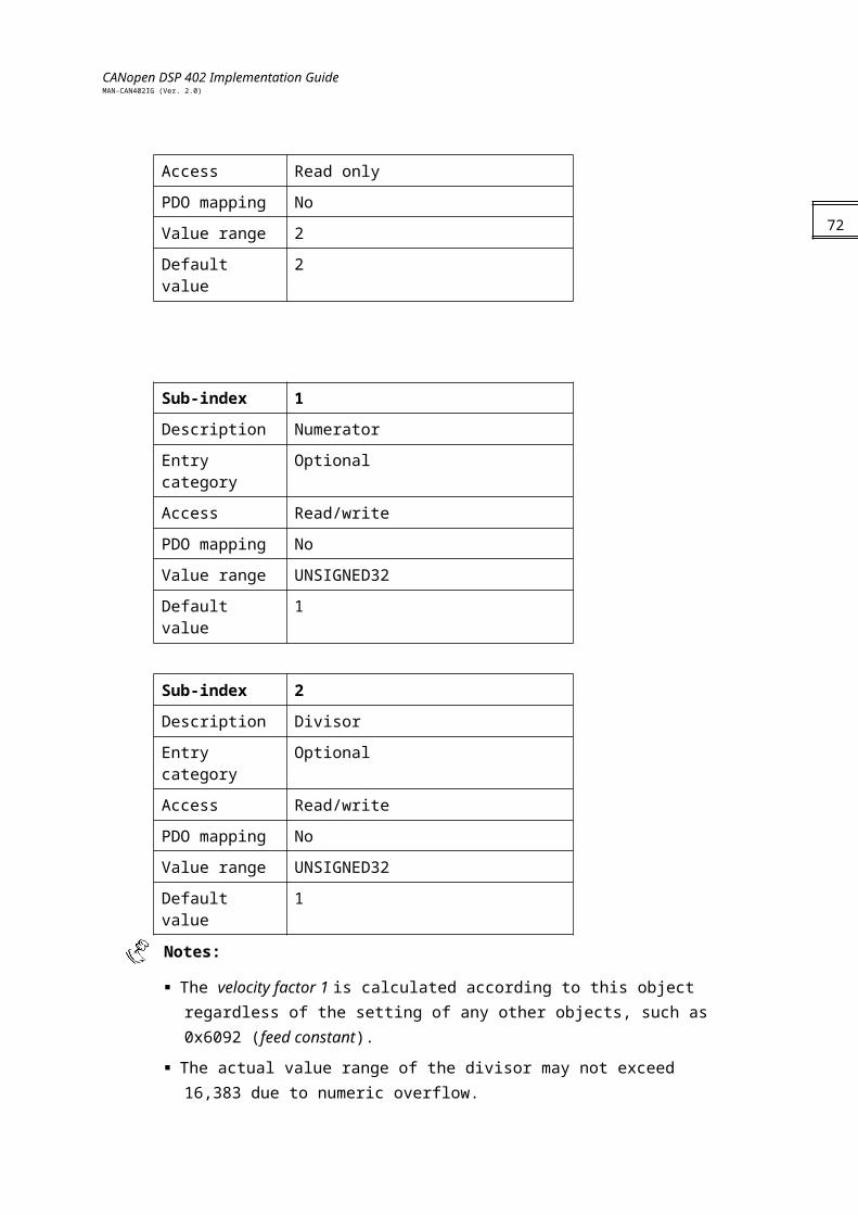
CANopen DSP 402 Implementation GuideMAN-CAN402IG (Ver. 2.0)
Data type UNSIGNED32
Category Optional
74
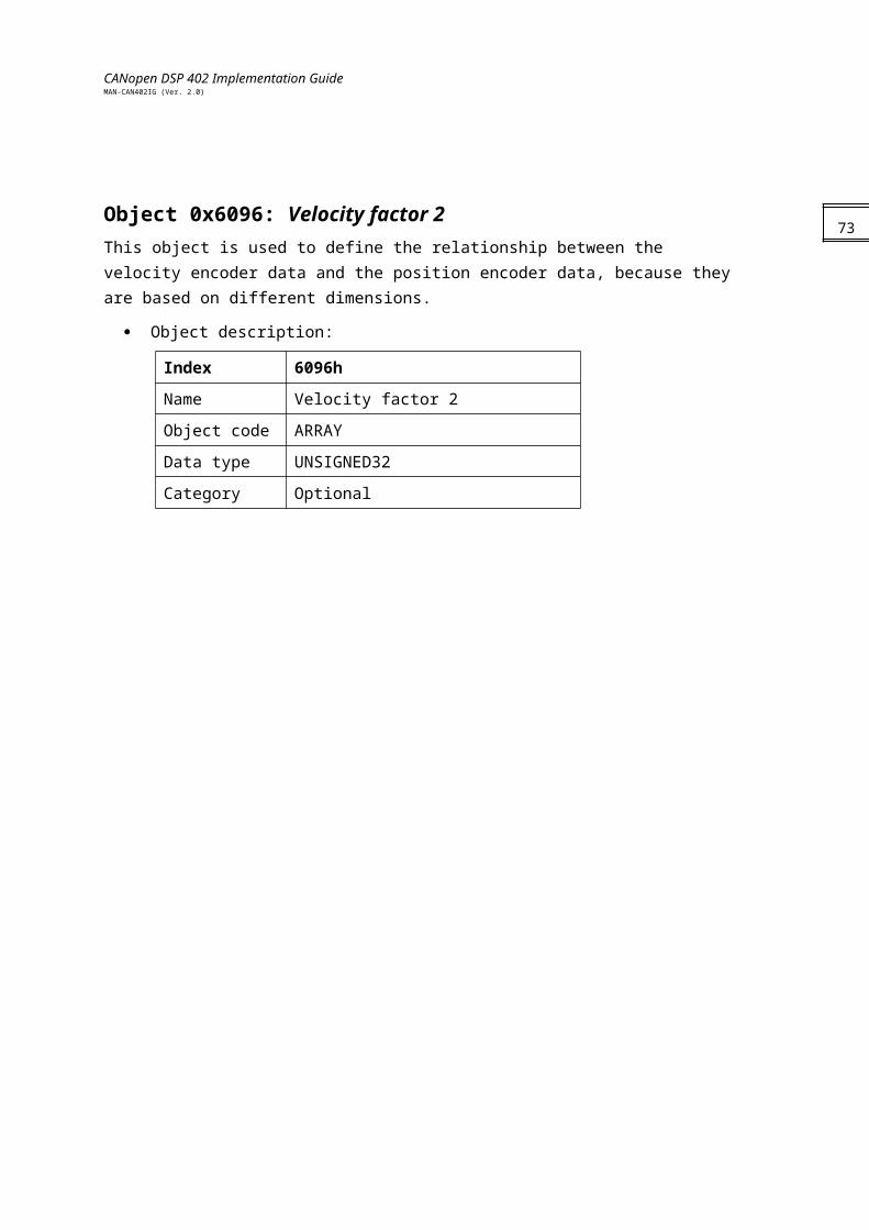
CANopen DSP 402 Implementation GuideMAN-CAN402IG (Ver. 2.0)
Entry description:
Access Read/write
PDO mapping No
Value range UNSIGNED32
Default value 0
Object 0x6066: Following error time out When a following error occurs longer than the defined value of the timeout, given in multiples of milliseconds, the corresponding bit 13 following error in the statusword is set to 1. No further reaction is taken.
The Elmo drive setup parameter for position following error is ER[3]. When the following
error exceeds this value, the drive aborts the motion, the motor continues to run through its own inertia and the DSP 402 status is “switch on disable.”
Object description:
Index 6066h
Name Following error time out
Object code VAR
Data type UNSIGNED16
Category Optional
Entry description:
Access Read/write
PDO mapping No
Value range UNSIGNED16
Default value 0
75
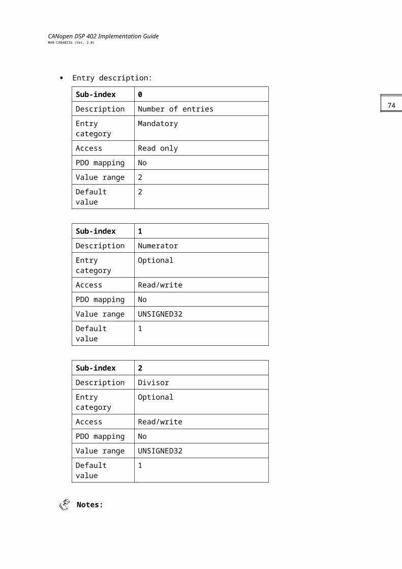
CANopen DSP 402 Implementation GuideMAN-CAN402IG (Ver. 2.0)
Object 0x6067: Position window This object defines a symmetrical range of accepted positions relative to the target position. If the actual value of the position encoder is within the position window, this target position is regarded as reached. Because the position window is usually specified in user-defined units, the position factor must be used to transform this value into increments. Before it can be used with this function, the target position must be handled in the same manner as in the trajectory generator for limiting functions and transformation into internal machine units.
The Elmo drive always checks the target position window in its own setup parameters
TR[1] and TR[2] at the real-time level. Therefore, the following points must be taken into account:
The position error mechanism cannot be switched off.
The limits of the position window and the position window time (in internal units) are 32,000 increments and 100 milliseconds, respectively.
Object description:
Index 6067h
Name Position window
Object code VAR
Data type UNSIGNED32
Category Optional
Entry description:
Access Read/write
PDO mapping No
Value range UNSIGNED32
Default value No
Object 0x6068: Position window timeWhen the actual position is within the position window during the defined position window time — given in multiples of milliseconds — the corresponding bit 10 target reached in the statusword is set to 1. Refer to the description in the position window object.
Object description:
Index 6068h
Name Position window time
Object code VAR
Data type UNSIGNED16
76

CANopen DSP 402 Implementation GuideMAN-CAN402IG (Ver. 2.0)
Category Optional
Entry description:
Access Read/write
PDO mapping No
Value range UNSIGNED16 (note in object 6067h)
Default value 20
Object 0x60FC: Position demand value - increments This output of the trajectory generator in profile position mode is an internal value using increments.
Object description:
Index 60FCh
Name Position demand value - increments
Object code VAR
Data type INTEGER32
Category Optional
Entry description:
Access Read only
PDO mapping Yes
Value range INTEGER32
Default value 0
77
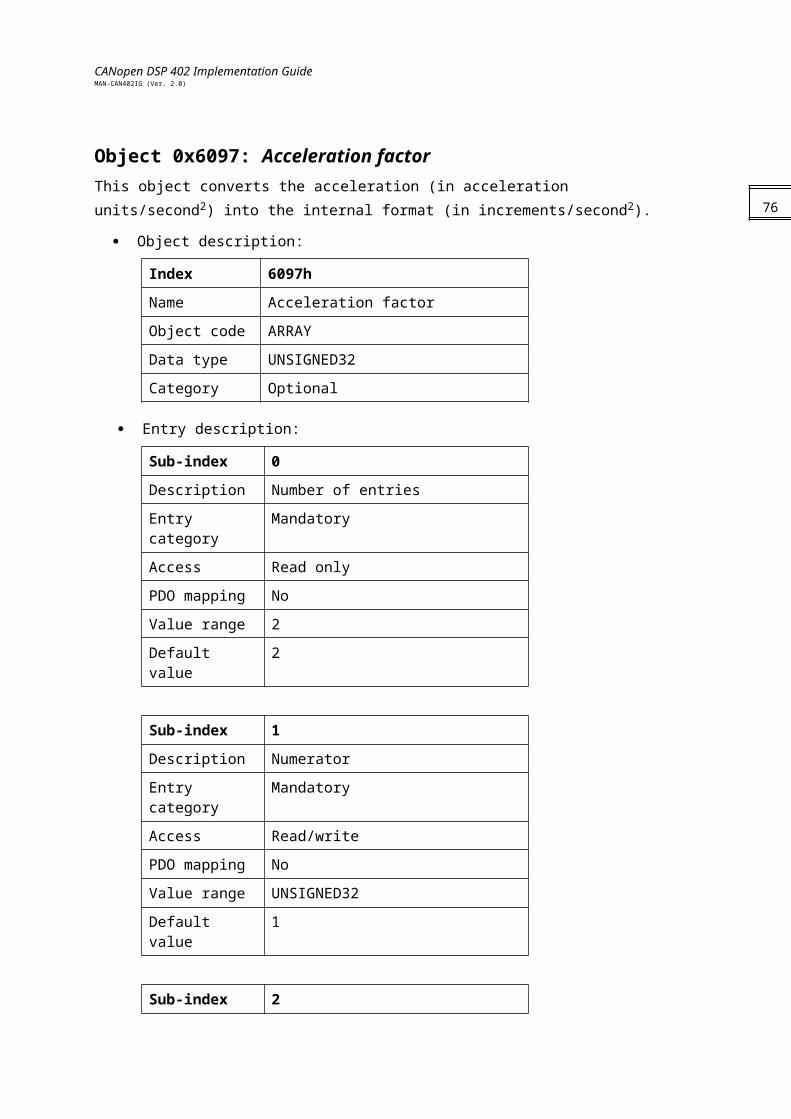
CANopen DSP 402 Implementation GuideMAN-CAN402IG (Ver. 2.0)
Chapter 11: Profiled Position607Ah: Target position
607Bh: Position range limit
607Dh: Software position limit
607Fh: Maximum profile velocity
6081h: Profiled velocity
6082h: End velocity
6083h: Profiled acceleration
6084h: Profiled deceleration
6086h: Motion profile type
General InformationThis chapter describes how to set a point-to-point (PTP) movement under a profiled position where a target position is applied to the trajectory generator. It generates a position demand value to the control loop. The trajectory generator input includes profiled velocity, acceleration, deceleration, and selection of motion type, motion polarity and stopping option. The inputs to the trajectory are given in user units and are limited before being normalized to internal increments.
Notes:
Limits supported by the DSP 402 protocol may be submitted to internal limits that protect the drive or support any previous behavior for compatibility reasons.
The velocity, acceleration, deceleration is submitted to the limits according to the relevant limit range.
Controlword of the profiled position mode:
Bit Function
0…3 Described in Device Control
4 Set new point
5 Change set immediately
6 Absolute/relative movement
7 Described in Device Control
8 Halt
9..12 Described in Device Control
13 New point is buffered
14..15 Described in Device Control
78
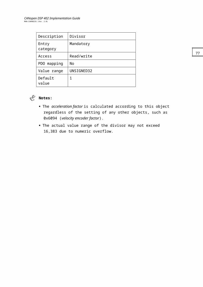
CANopen DSP 402 Implementation GuideMAN-CAN402IG (Ver. 2.0)
Name Value Description
New set-point 0 Does not assume target position.
1 Assumes target position.
Change set immediately
0 Finish actual positioning and then start next positioning.
1 Interrupt actual positioning and start next positioning.
abs\rel 0 Target position is an absolute value.
1 Target position is a relative value.
Halt 0 Execute positioning.
1 Stop axle with profile acceleration.
New buffered point
0 New set point is not buffered.
1 New set point is buffered. Statusword of the profiled position mode:
Bit Function
0…9 Described in Device Control
10 Target reached
11 Described in Device Control
12 Set new point acknowledge
13 Following error
12…15 Described in Device Control
Name Value Description
Target reached 0 Halt = 0: Target position not reached.Halt = 1: Axle decelerates.
1 Halt = 0: Target position reached.Halt = 1: Velocity of axle is 0.
Set new point acknowledge
0 Trajectory generator has not assumed the positioning values (yet).
1 Trajectory generator has assumed the positioning values.
Following error 0
1 Following error.
Objects
79
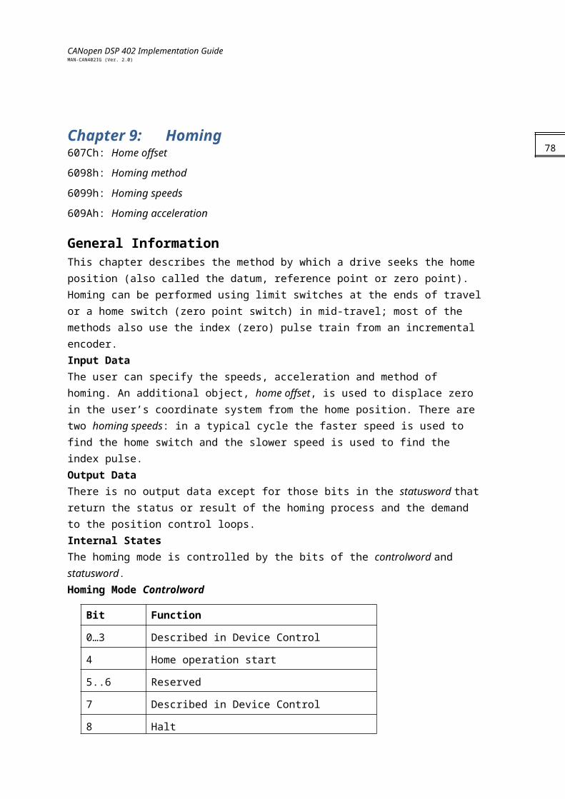
CANopen DSP 402 Implementation GuideMAN-CAN402IG (Ver. 2.0)
Object 0x607A: Target position The target position is the position to which the drive should move in position profile mode, using the current settings of motion control parameters such as velocity, acceleration, deceleration and motion profile type. The target position is given in user-defined position units. It is converted to position increments using the position factor. The target position is interpreted as absolute or relative, depending on the Abs/Rel flag in the controlword.
Object description:
Index 607Ah
Name Profile target position
Object code VAR
Data type INTEGER32
Category Mandatory
Entry description:
Access Read/write
PDO mapping No
Value range INTEGER32
Default value No
Object 0x607B: Position range limit This object contains two sub-parameters that limit the numerical range of the input value: min position range limit and max position range limit. On reaching or exceeding these limits, the input value automatically wraps to the other end of the range. Wrap-around of the input value can be prevented by setting software position limits.
Notes:
The high position range limit and the low position range limit must be even.
This object cannot be set while in OPERATION ENABLE or QUICK STOP state.
Object description:
Index 607Bh
Name Position range limit
Object code ARRAY
Data type INTEGER32
Category Mandatory
80

CANopen DSP 402 Implementation GuideMAN-CAN402IG (Ver. 2.0)
Entry description:
Sub-index 0
Description Number of entries
Entry category Mandatory
Access Read only
PDO mapping No
Value range 2
Default value 2
Sub-index 1
Description Min position range limit
Entry category Mandatory
Access Read/write
PDO mapping No
Value range INTEGER32
Default value No
Sub-index 2
Description Max position range limit
Entry category Mandatory
Access Read/write
PDO mapping No
Value range INTEGER32
Default value No
The value of the position range limit is reflected in the XM[1] and XM[2] commands, to
which the range and restrictions are ultimately submitted (refer to the SimplIQ Command Reference Manual).
81
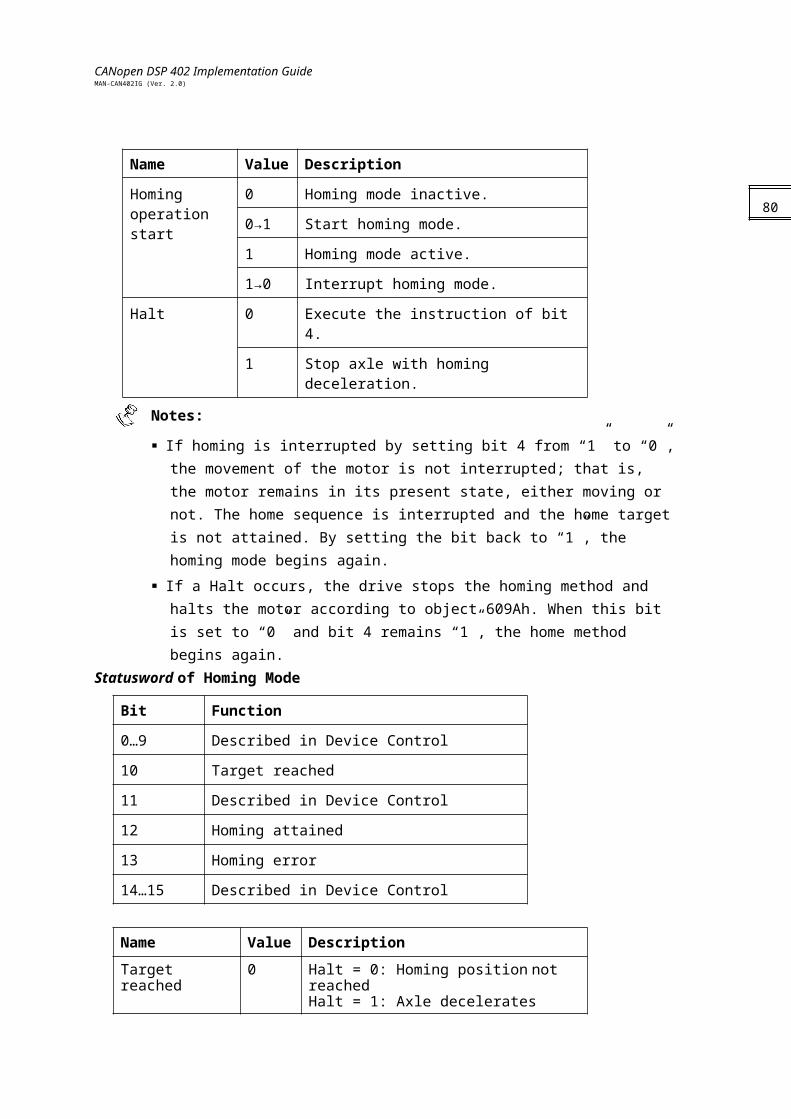
CANopen DSP 402 Implementation GuideMAN-CAN402IG (Ver. 2.0)
Object 0x607D: Software position limit This object contains the sub-parameters min position limit and max position limit, which define the absolute position limits for the position demand value and the position actual value. Every new target position must be checked against these limits. The position limits are specified in position units (same as target position) and are always relative to the machine home position.
Before being compared with the target position, the position limit must be corrected internally by the home offset, as follows:
Internal correct minimum position limit = min position limit - home offset
Internal corrected maximum position limit = max position limit - home offsetThis calculation is performed when home offset or software position limit is changed.
Object description:
Index 607Dh
Name Software position limit
Object code ARRAY
Data type INTEGER32
Category Mandatory
Entry description:
Sub-index 0
Description Number of entries
Entry category Mandatory
Access Read only
PDO mapping No
Value range 2
Default value 2
Sub-index 1
Description Min position limit
Entry category Mandatory
Access Read/write
PDO mapping No
Value range INTEGER32
Default value No
82
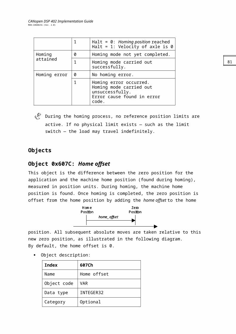
CANopen DSP 402 Implementation GuideMAN-CAN402IG (Ver. 2.0)
Sub-index 2
Description Max position limit
Entry category Mandatory
Access Read/write
PDO mapping No
Value range INTEGER32
Default value No
The value of the software position limit is reflected in the VH[3] and VL[3] commands, to
which the range and restrictions are ultimately submitted (refer to the SimplIQ Command Reference Manual).
Object 0x607F: Max profile velocity The max profile velocity is the maximum speed allowed in either direction during a profiled move. It is given in the same units as profile velocity.
Object description:
Index 607Fh
Name Max profile velocity
Object code VAR
Data type UNSIGNED32
Category Optional
Entry description:
Access Read/write
PDO mapping No
Value range UNSIGNED32
Default value No
The value of this object is limited internally to the maximum allowed velocity as
reflected in VH[2] and VL[2].
83
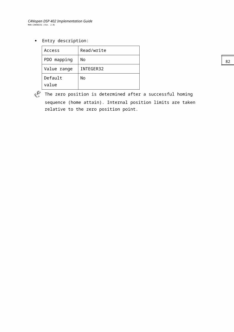
CANopen DSP 402 Implementation GuideMAN-CAN402IG (Ver. 2.0)
Object 0x6081: Profile velocity This object is the velocity normally attained at the end of the acceleration ramp during a profiled move and is valid for both directions of motion. The profile velocity is given in user-defined speed units. It is converted to position increments per second using the velocity encoder factor.
Object description:
Index 6081h
Name Profile velocity
Object code VAR
Data type UNSIGNED32
Category Optional
Entry description:
Access Read/write
PDO mapping No
Value range UNSIGNED32
Default value No
The value and default value of the profile velocity is reflected in the SP command, to
which the range and restrictions are ultimately submitted (refer to the SimplIQ Command Reference Manual).
Object 0x6082: End velocity (not yet implemented) The end velocity defines the velocity required by the drive upon reaching the target position. Normally, the drive stops at the target position; that is, the end velocity = 0. The end velocity is given in the same units as profile velocity.
Object description:
Index 6082h
Name End velocity
Object code VAR
Data type UNSIGNED32
Category Optional
Entry description:
Access Read/write
PDO mapping No
Value range UNSIGNED32
84
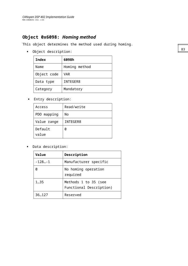
CANopen DSP 402 Implementation GuideMAN-CAN402IG (Ver. 2.0)
Default value 0
Object 0x6083: Profile acceleration The profile acceleration is given in user-defined acceleration units. It is converted to position increments per second2 using the normalizing factors.
Object description:
Index 6083h
Name Profile acceleration
Object code VAR
Data type UNSIGNED32
Category Optional
Entry description:
Access Read/write
PDO mapping No
Value range UNSIGNED32
Default value No
The value of the profile acceleration is reflected in the AC command, to which the range
and restrictions are ultimately submitted (refer to the SimplIQ Command Reference Manual).
Object 0x6084: Profile deceleration The profile deceleration is given in the same units as profile acceleration. If the end velocity (object 0x6082) is different than 0, this object is not valid and the profiled deceleration is considered to be similar to the profiled acceleration.
Object description:
Index 6084h
Name Profile deceleration
Object code VAR
Data type UNSIGNED32
Category Optional
Entry description:
Access Read/write
85
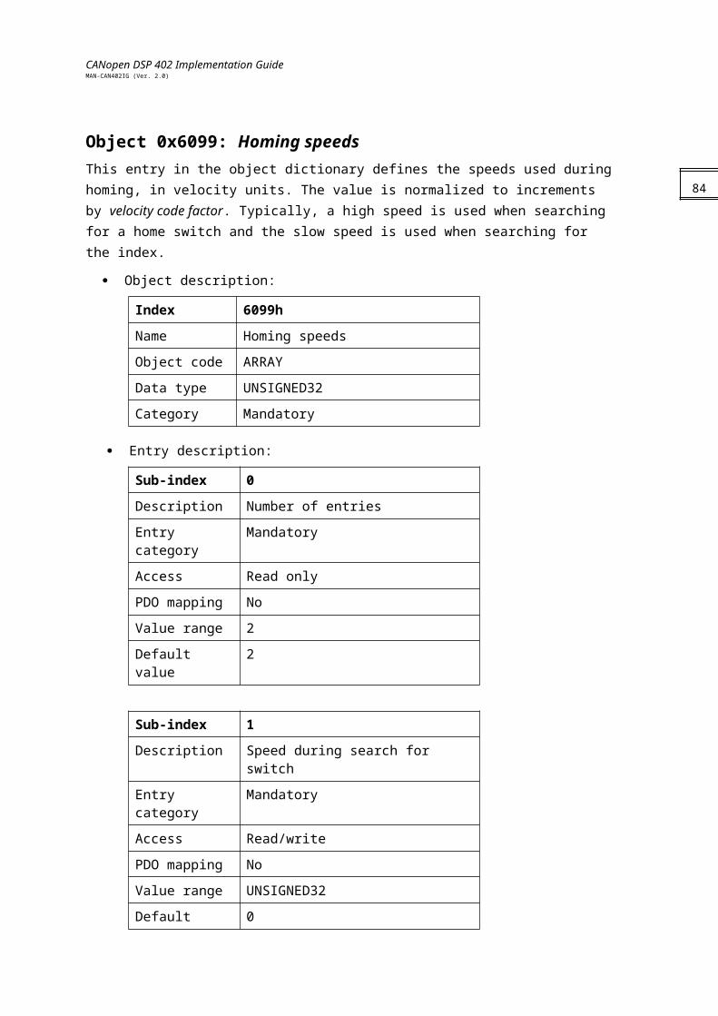
CANopen DSP 402 Implementation GuideMAN-CAN402IG (Ver. 2.0)
PDO mapping No
Value range UNSIGNED32
Default value No
The value of the profile deceleration is reflected in the DC command, to which the range
and restrictions are ultimately submitted (refer to the SimplIQ Command Reference Manual).
Object 0x6085: Quick stop deceleration The quick stop deceleration is the deceleration used to stop the motor if the Quick Stop command is given and the quick stop option code (see 605Ah) is set to 2. The quick stop deceleration is given in the same units as the profile acceleration.
Object description:
Index 6085h
Name Quick stop deceleration
Object code VAR
Data type UNSIGNED32
Category Optional
Entry description:
Access Read/write
PDO mapping No
Value range UNSIGNED32
Default value 0
Object 0x6086: Motion profile type This object is used to select the type of motion profile used to perform a profile move.
Object description:
Index 6086h
Name Motion profile type
Object code VAR
Data type INTEGER16
Category Mandatory
Entry description:
86
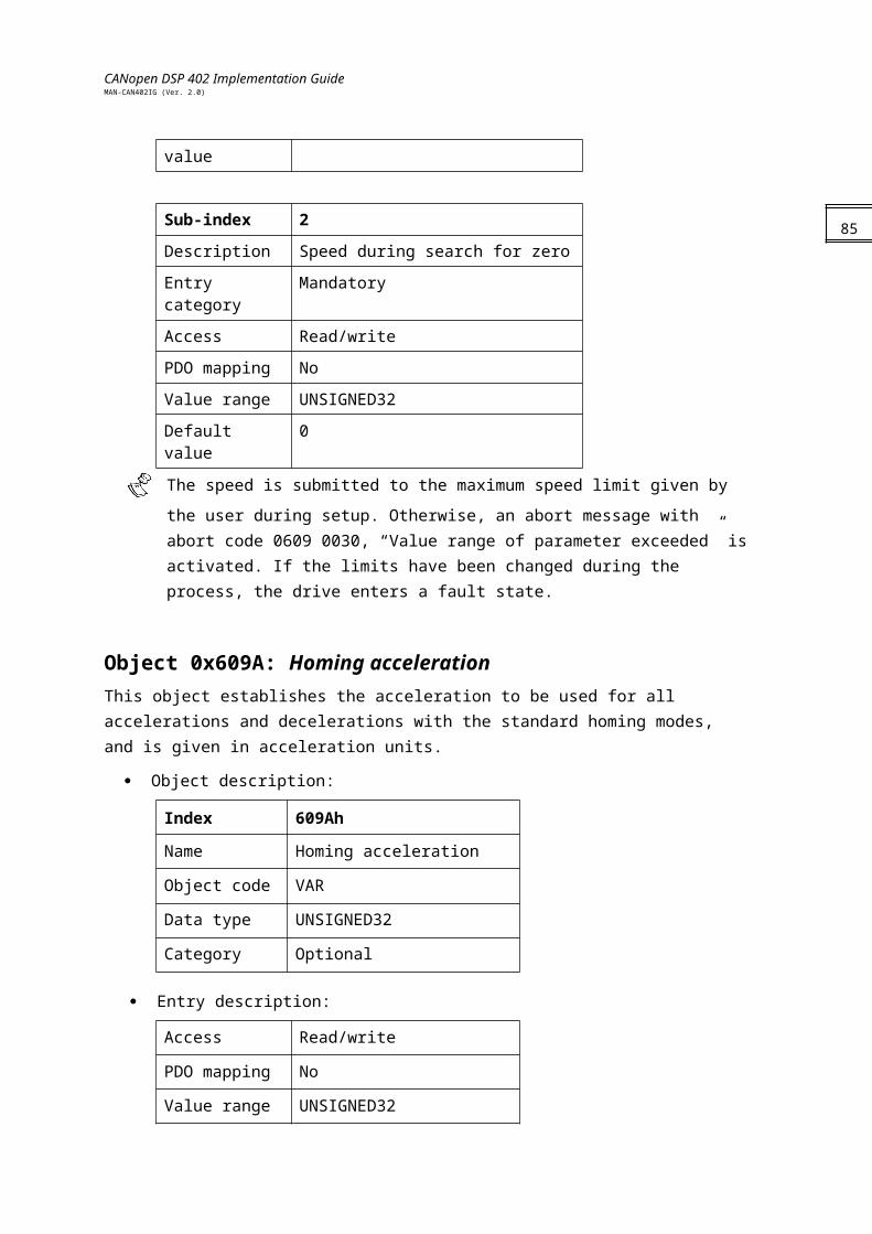
CANopen DSP 402 Implementation GuideMAN-CAN402IG (Ver. 2.0)
Access Read/write
PDO mapping No
Value range INTEGER16
Default value 0
Data description:
Value Description
-32,768…-1 Manufacturer specific
0 Linear ramp (trapezoidal profile)
1 Not supported
2 Not supported
3 Not supported
4…32,767 Reserved
Functional DescriptionTwo different means of applying target positions to a drive are supported by this device profile:
Set of set-points:After reaching the target position, the drive unit immediately processes the next target position that results in a move in which the velocity of the drive is not normally reduced to zero after achieving a set-point.
Single set-point:After reaching the target position, the drive unit signals this status to a host computer and then receives a new set-point. After reaching a target position, the velocity is normally reduced to zero before starting a move to the next set-point.
The two modes are controlled by the timing of the bits “new set-point” and “change set immediately” in the controlword, and “set-point acknowledge” in the statusword. These bits allow a request-response mechanism to be set up in order to prepare a set of set-points while another set is still being processed in the drive unit. This minimizes reaction times within a control program on a host computer.The beginning of the movement is dependent on bit 1 of the object 0x2f41. The default status of this bit is 0. In this case, movement begins after the bit “new Set-point” (bit 4) of controlword ascends and descends. In the case that bit 1 of the object 0x2f41 is Set, movement begins when the bit “new Set-point” (bit 4) of controlword goes from ‘0’ to ‘1’. More information about this object is available in the CANopen DS 301 Implementation Guide.The Elmo drive introduces a buffered mode (bit 13 in the controlword), in which up to 16 subsequent profiled motions can be programmed. The programmed profiles are executed when the previous motion is target reached. In buffered motion, set-point acknowledge behaves in a manner similar to non-buffered mode, whereby the bit is reset when new data can be buffered.
87
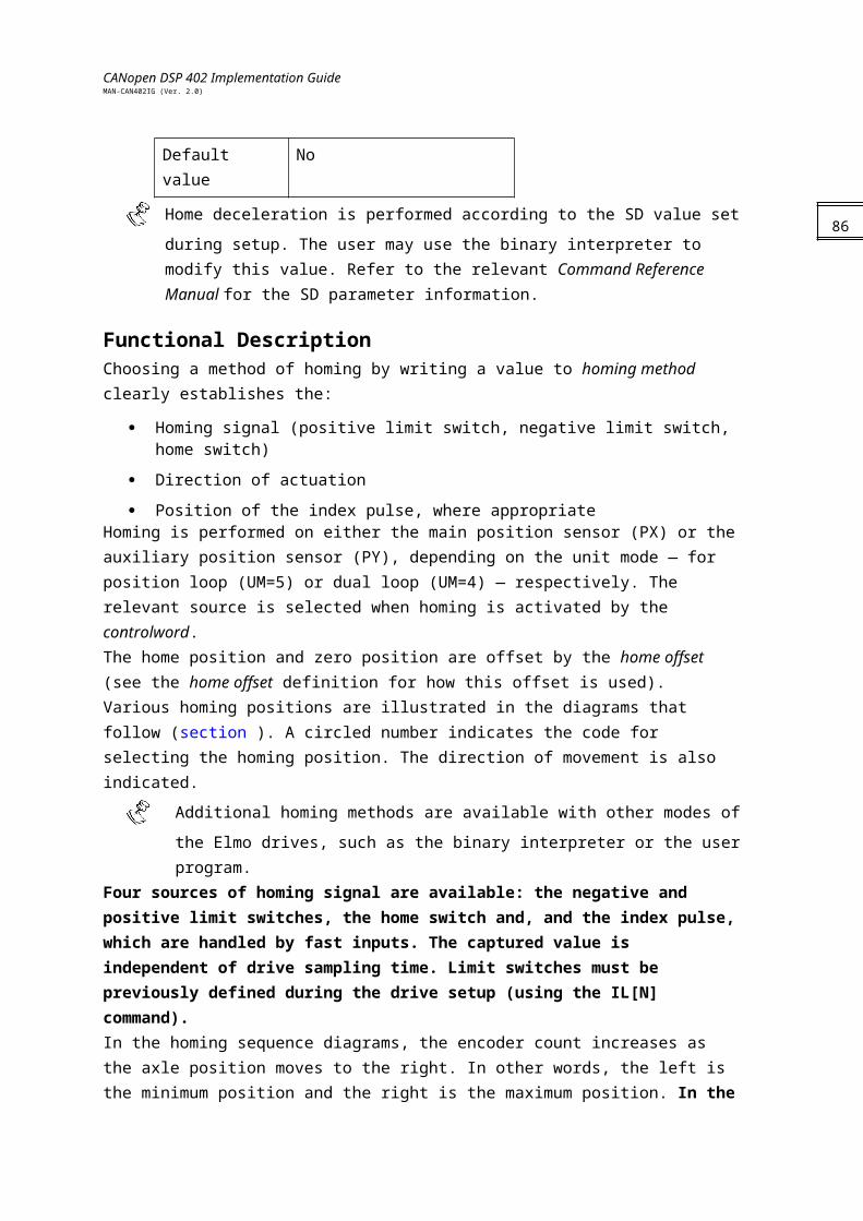
CANopen DSP 402 Implementation GuideMAN-CAN402IG (Ver. 2.0)
Using change set immediately interrupts the buffered motion. In this case, the buffer is reset and the last programmed motion is executed immediately.The sequence of a set new point is:
1. The host sends the trajectory data and validates it by setting the new set point.
2. The Elmo drive acknowledges reception and buffering of the new data by setting set-point acknowledge.
3. The host sends a command to start the first motion by resetting the new set point.
4. The motion begins. If the drive can accept more set points, the set-point acknowledge resets.
5. Unless it was interrupted by a change set immediately, the next trajectory is executed as soon as a target reached is set.
Notes:
A target position can be programmed at any status but can be executed only in ENABLE OPERATION state. Otherwise, an emergency message is transmitted.
The amount of buffered data can be received by object 0x2F15.
88
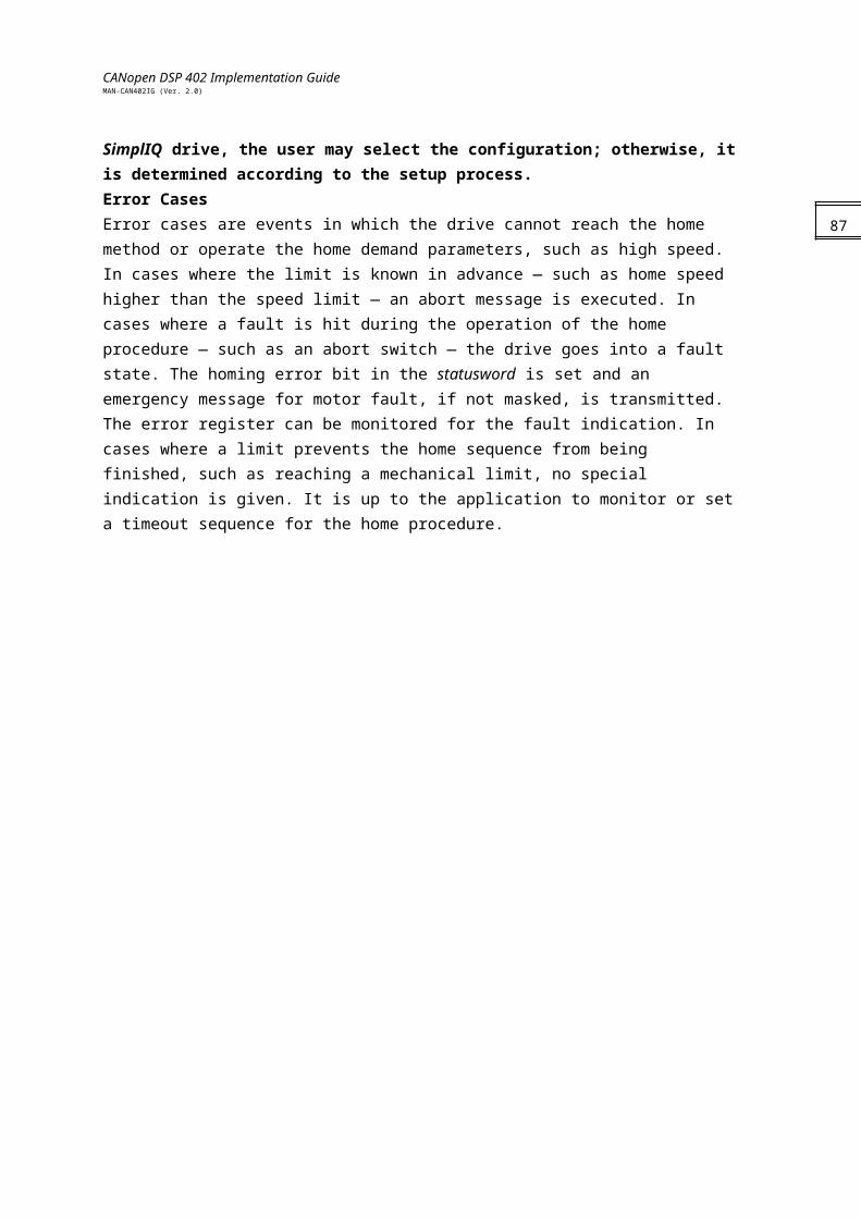
CANopen DSP 402 Implementation GuideMAN-CAN402IG (Ver. 2.0)
Chapter 12: Interpolated Position60C0h: Interpolation sub mode select
60C1h: Interpolation data record
60C2h: Interpolation time period
60C3h: Interpolation sync definition
60C4h: Interpolation data configuration
General InformationInterpolated Position mode is used to control multiple coordinated axles or a single axle with the need for time-interpolation of set-point data. The mode normally uses time synchronization mechanisms like the sync object for a time coordination of the related drive units.The interpolation data record contains the interpolation data; the data type and the data size of the sub-indices of this structure are according to the sub-mode, as described in object 0x60C0. For all cases of motion, the interpolation cycle time is defined by the object interpolation time period. Time synchronization can be performed by the Sync message defined in DS301 (refer to the Elmo CANopen Implementation Guide).Interpolated Position mode allows a host controller to transmit a stream of interpolation data with an explicit time reference to the drive. The Elmo drive supports an input buffer that allows the interpolation data to be sent in bursts rather than continuously in real time. The actually available and the maximum size of the input buffer can be requested by the host using the interpolation data configuration. The buffer size is the number of interpolation data records that may be sent to a drive to fill the input buffer; it is not the size in bytes. The interpolation algorithm is defined in the interpolation sub mode select. Linear interpolation is the default interpolation method. For each interpolation cycle, the drive calculates a position demand value by interpolating interpolation data over a period of time.
Limit functions of speed acceleration deceleration and position are applied to the interpolation data.Internal statesThe interpolated position mode is controlled by the bits of the controlword and statusword.
89
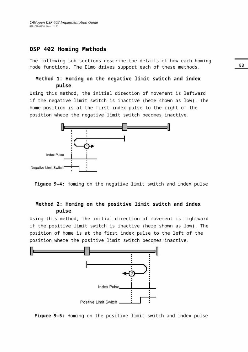
CANopen DSP 402 Implementation GuideMAN-CAN402IG (Ver. 2.0)
Interpolation inactiveThe state entered when the device is in OPERATION ENABLED state and Interpolated Position mode is selected and displayed (object 0x6061). The drive unit accepts input data and buffers it for interpolation calculations, but does not move the axles.
Interpolation activeThe state entered when the device is in OPERATION ENABLED state, the interpolated position mode is selected and it is enabled. The drive unit accepts input data and moves the axles.
Buffer resetBuffer points start from the first entry. The interpolation buffer is reset in the following cases:
Entering Interpolated Position mode
Modifying Interpolation sub-mode.
Entering INTERPOLATION INACTIVE state
Setting buffer clear state in object 0x60C4
Motion is halted
90
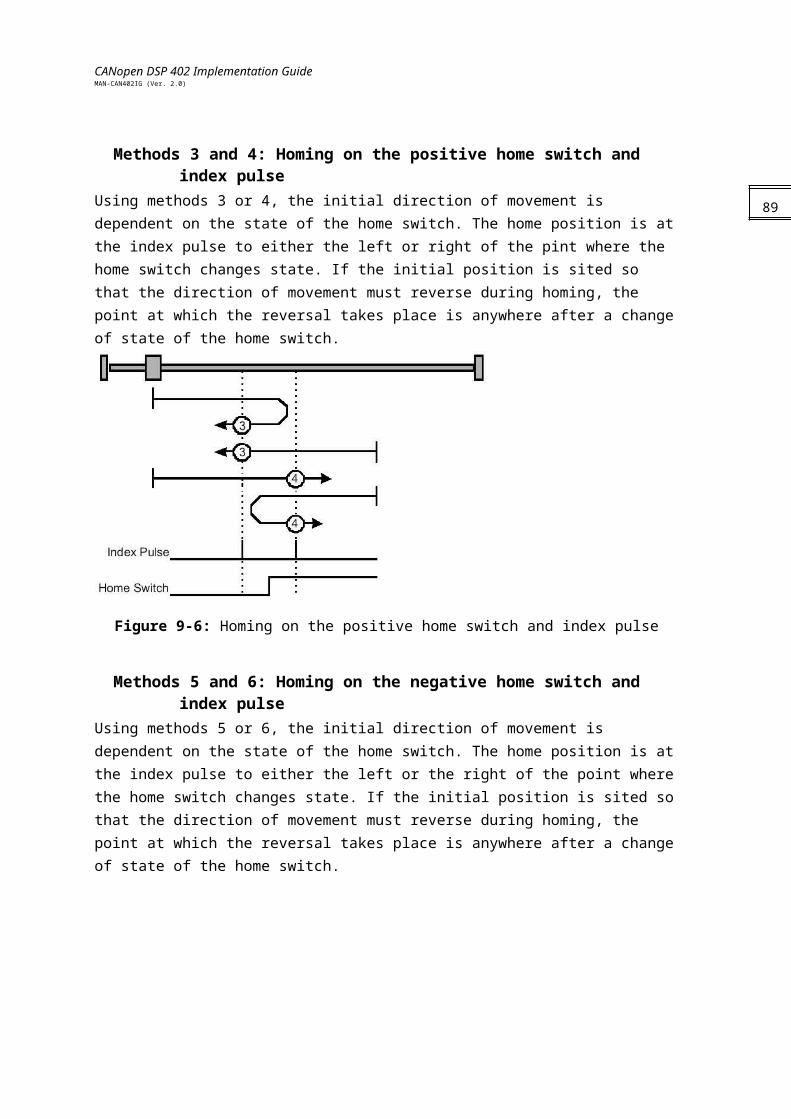
CANopen DSP 402 Implementation GuideMAN-CAN402IG (Ver. 2.0)
Controlword of Interpolated Position mode:
Name Value Description
Enable ip mode 0 Interpolated position mode is inactive.
1 Interpolated position mode is active.
Halt 0 Execute the instruction of bit 4.
1 Stop axle according to halt option code.
Notes:
If the interpolation is interrupted by setting bit 4 from 1 to 0, the drive stops at quick stop deceleration (object 0x6085) and is treated similarly to axis halted. In this case, the buffer is cleared; that is, the actual buffer size is the maximum buffer size.
Setting bit 4 to 1 always starts the interpolation from the first data record. It is up to the user to ensure consistency of the trajectory.
In case of a Halt, the drive stops the interpolation and stops the motor according to object 0x605D. This case is treated similarly to interpolation interrupted described previously.
In case the motor is stopped due to an internal fault or controlword command, the interpolation is disabled, even if bit 4 is 1. Interpolation can be enabled again only after the device enters the OPERATION_ENABLE state and bit 4 is set to 1.
Statusword of Interpolated Position mode:
Bit Function
0…9 Described in Device Control
10 Target reached
11 Described in Device Control
12 Ip mode active.
13 Reserved
14…15 Described in Device Control
Name Value Description
Target reached 0 Halt = 0: Position not reached.Halt = 1: Axle decelerates.
1 Halt = 0: Position reached.Halt = 1: Velocity of axle is 0.
IP mode active 0 Interpolation mode not active.
1 Interpolation mode active.
Setting bit 4 from 0 to 1 starts the interpolation from the first entry of the interpolation buffer.
91
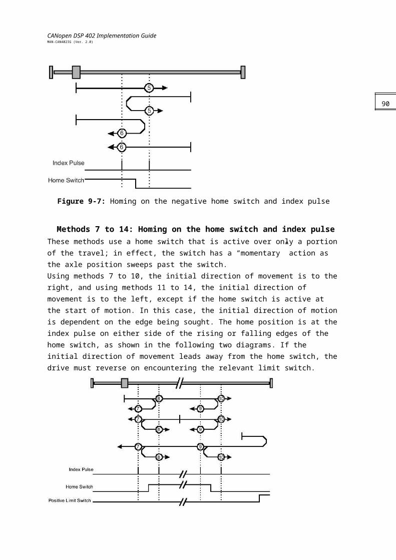
CANopen DSP 402 Implementation GuideMAN-CAN402IG (Ver. 2.0)
Objects
Object 0x60C0: Interpolation sub mode selectThis object reflects or changes the actual chosen interpolation mode, selected by the user.The interpolation sub-modes can be changed only when the interpolated mode is inactive. When modifying the interpolation mode, a new mapping (if needed) of object 0x60C1 must be made after the sub mode is modified. Failing to do so may cause unpredictable results.
Object description:
Index 60C0h
Name Interpolated sub mode select
Object code VAR
Data type INTEGER16
Category Optional
Entry description:
Access Read/write
PDO mapping No
Value range -1...0
Default value 0 (linear interpolation)
Data description:
Value Description
-32768..-2 Reserved
-1 Cubic spline (PV)
0 Linear interpolation
1…32767 Reserved
92
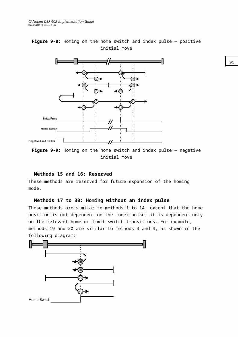
CANopen DSP 402 Implementation GuideMAN-CAN402IG (Ver. 2.0)
Object 0x60C1: Interpolation data recordThis object is the data words, which are necessary for performing the interpolation algorithm. The interpretation of the data words may vary with the different possible interpolation modes as set by 60C0h.
Object description:
Index 60C1h
Name Interpolation data record
Object code ARRAY
Data type 60C0h = -1 : DSP402 PV data record (0x44)60C0h = 0 : INTEGER3260C0h > 0 : not defined
Category Optional
Entry description:
Sub-index 0
Description Number of entries
Entry category Mandatory
Access Read only
PDO mapping Yes
Value range 1
Default value 1
Sub-index 1
Description Parameter of the IP function
Entry category Mandatory
Access Read/Write
PDO mapping Yes
Value range 60C0h = -1 : DSP 402 PV data record (0x44)60C0h = 0 : INTEGER3260C0h > 0 : not defined
Default value No
93
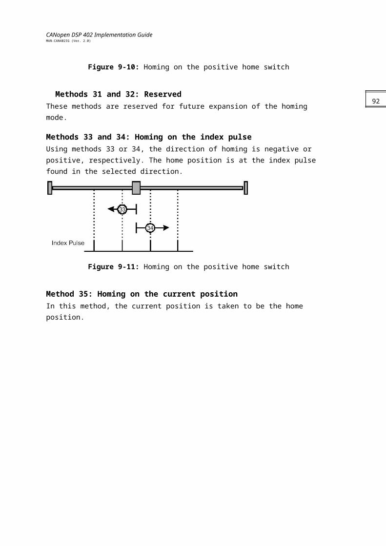
CANopen DSP 402 Implementation GuideMAN-CAN402IG (Ver. 2.0)
Object 0x60C2: Interpolation time periodThis object is used to define the relative time taken between two set points for the interpolation position modes. The interpolation time unit is given in 10interpolation time index seconds.The interpolation time period can be changed only when the interpolated mode is inactive.
Object description:
Index 60C2h
Name Interpolation time period
Object code RECORD
Data type Interpolation time period (object 0x80)
Category Optional
Entry description:
Sub-index 0
Description Number of entries
Entry category Mandatory
Access Read only
PDO mapping Yes
Value range 2
Default value 2
Sub-index 1
Description Interpolation time unit
Entry category Mandatory
Access Read/Write
PDO mapping Yes
Value range 1…255
Default value 1
Sub-index 2
Description Interpolation time index
Entry category Mandatory
Access Read only
PDO mapping No
Value range -3 , -4 (refer to Appendix B)
Default value -3
The interpolated time period is always in milliseconds (10-3 seconds) regardless of sub-
index 2, Interpolation time index.
94
CANopen DSP 402 Implementation GuideMAN-CAN402IG (Ver. 2.0)
Object 0x60C3: Interpolation sync definitionDevices in the interpolation position mode often interact with other devices. Therefore it is necessary to define a communication object, which is used to synchronize these interactions. This can be done by the general Sync as described in /3/, or a specific group-sync-signal. Each reception of this trigger-signal or a specified number of occurrences of the trigger-signal can synchronize the devices.
Description of synchronize on group:
Value Description0 General Sync is used1…255 Reserved
Object description:
Index 60C3h
Name Interpolation sync definitionObject code ARRAYData type UNSIGNED8Category Optional
Entry description:
Sub-index 0Description Number of entriesEntry category MandatoryAccess Read onlyPDO mapping NoValue range 2Default value 2
Sub-index 1Description Synchronize on groupEntry category MandatoryAccess Read onlyPDO mapping NoValue range UNSIGNED8Default value 0
Sub-index 2Description IP sync every n eventEntry category MandatoryAccess Read/WritePDO mapping NoValue range UNSIGNED8Default value 1
95
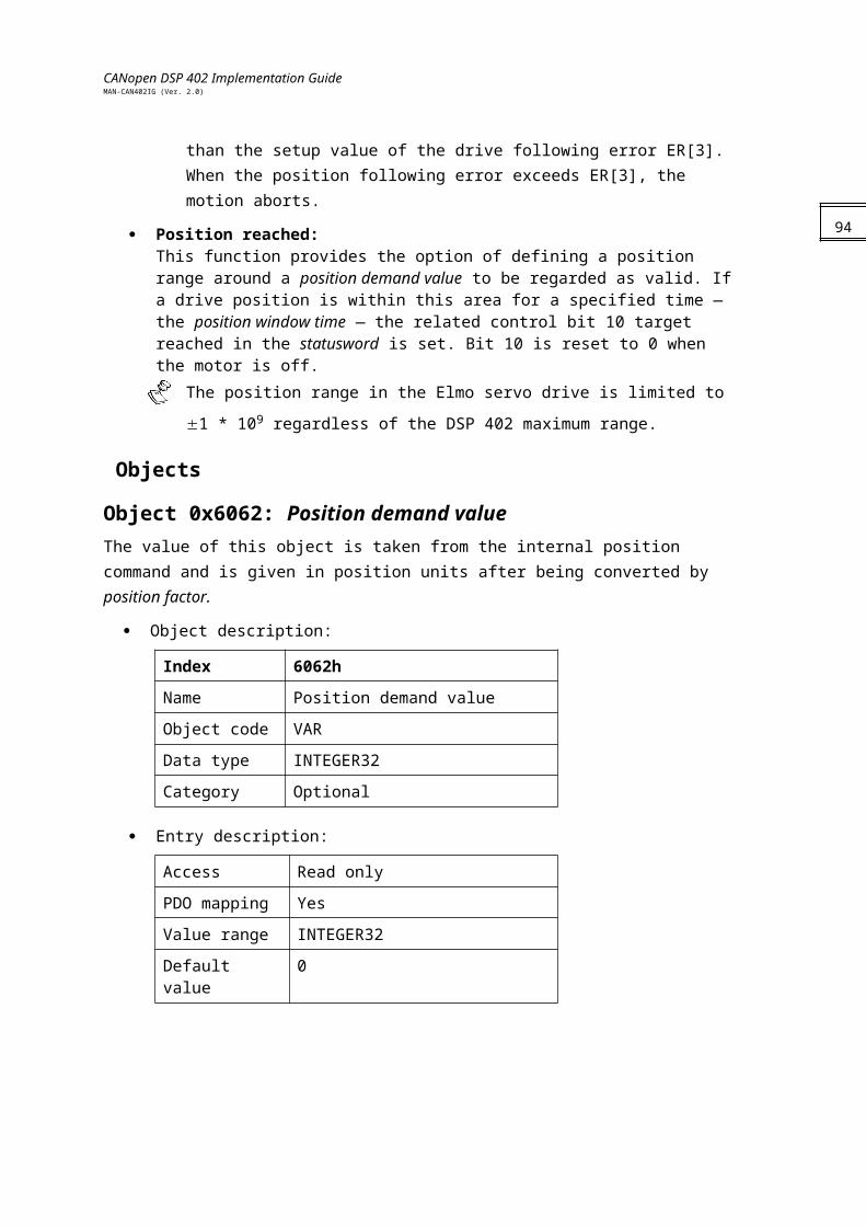
CANopen DSP 402 Implementation GuideMAN-CAN402IG (Ver. 2.0)
Object 0x60C4: Interpolation data configurationThe interpolation data configuration enables the user to get information about the buffer size and set the buffer configuration and strategy.
Type of buffer organization:
Value Description0 FIFO buffer1 Ring buffer2…255 Reserved
Description of buffer clear values:
Value Description0 Clear input buffer
Access disabled Clear all Ip data records
1 Enable access to input buffer for drive functions2…255 Reserved
Object description:
Index 60C4h
Name Interpolated data configuration
Object code RECORD
Data type Interpolated data configuration record (object 0x81)
Category Optional
Entry description:Access Read/WritePDO mapping YesValue range UNSIGNED32Default value No
Sub-index 0Description Number of entriesEntry category MandatoryAccess Read onlyPDO mapping NoValue range 6Default value 6
96

CANopen DSP 402 Implementation GuideMAN-CAN402IG (Ver. 2.0)
Sub-index 1Description Maximum buffer sizeEntry category MandatoryAccess Read onlyPDO mapping NoValue range UNSIGNED32Default value 1
Sub-index 2Description Actual buffer sizeEntry category MandatoryAccess Read/WritePDO mapping NoValue range UNSIGNED32Default value 0
Sub-index 3Description Buffer organizationEntry category MandatoryAccess Read/WritePDO mapping NoValue range 0…1 (described on following pages)Default value 0
Sub-index 4Description Buffer positionEntry category MandatoryAccess Read/WritePDO mapping YesValue range UNSIGNED16Default value 1
Sub-index 5Description Size of data recordEntry category MandatoryAccess Read onlyPDO mapping NoValue range 60C0h = -1 : 8 bytes
60C0h = 0: 4 bytesDefault value INTEGER32
97
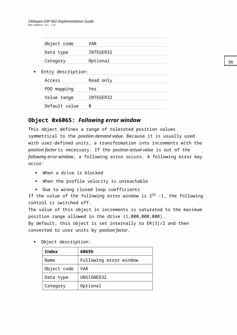
CANopen DSP 402 Implementation GuideMAN-CAN402IG (Ver. 2.0)
Sub-index 6Description Buffer clearEntry category MandatoryAccess Write onlyPDO mapping NoValue range UNSIGNED8 (described below)Default value 0
Notes:
The maximum and actual buffer size are the number of interpolated data records that may be sent to the drive to fill the input buffer. They are not the size in bytes. The actual buffer size may be between max buffer size to.
The buffer position has an effect when the ring buffer is selected.
The buffer organization may change only when interpolated mode is not active. Reorganization of the buffer clears the input buffer.
Buffer can be clear by sub-index 6 only if interpolation is not active.Buffer strategiesThe contents of the buffer items can only be accessed via the interpolation data record. The maximum buffer size is given in object 0x60C4 is used by the host to determine the actual buffer size.Commonly, first-in-first-out (FIFO) structures or ring buffers are used as input buffers.
FIFO:If the buffer is organized as FIFO, every new received interpolation data record is placed at the end of the queue, and the drive takes the next data record from the top of the queue. When the last item of a data record is stored, the buffer pointer is incremented in order to point to the next buffer position. With this buffer principle, the object buffer position has no affect. The FIFO buffer is organized as a cyclic buffer so that after the last buffer entry is updated (entry of max buffer size), the first entry may be available again depending on actual buffer size. When the buffer is full, an emergency is transmitted and the last message is discarded.
If buffer is empty interpolation is disabled and emergency may be transmitted if defined so by object 0x2F21 (refer to the Elmo CANopen Implementation Guide).
Ring buffer:If the buffer is structured as a ring, the host can place an interpolation data record into any valid position in the ring by changing the pointer defined in buffer position. Without changing the buffer position, all data records are written at the same location. The drive reads the next entry out of the buffer by an internal ring pointer. It is set to the first data record with buffer clear, after the reorganization of the input buffer. The user cannot exceed the max buffer
Functional Description
98
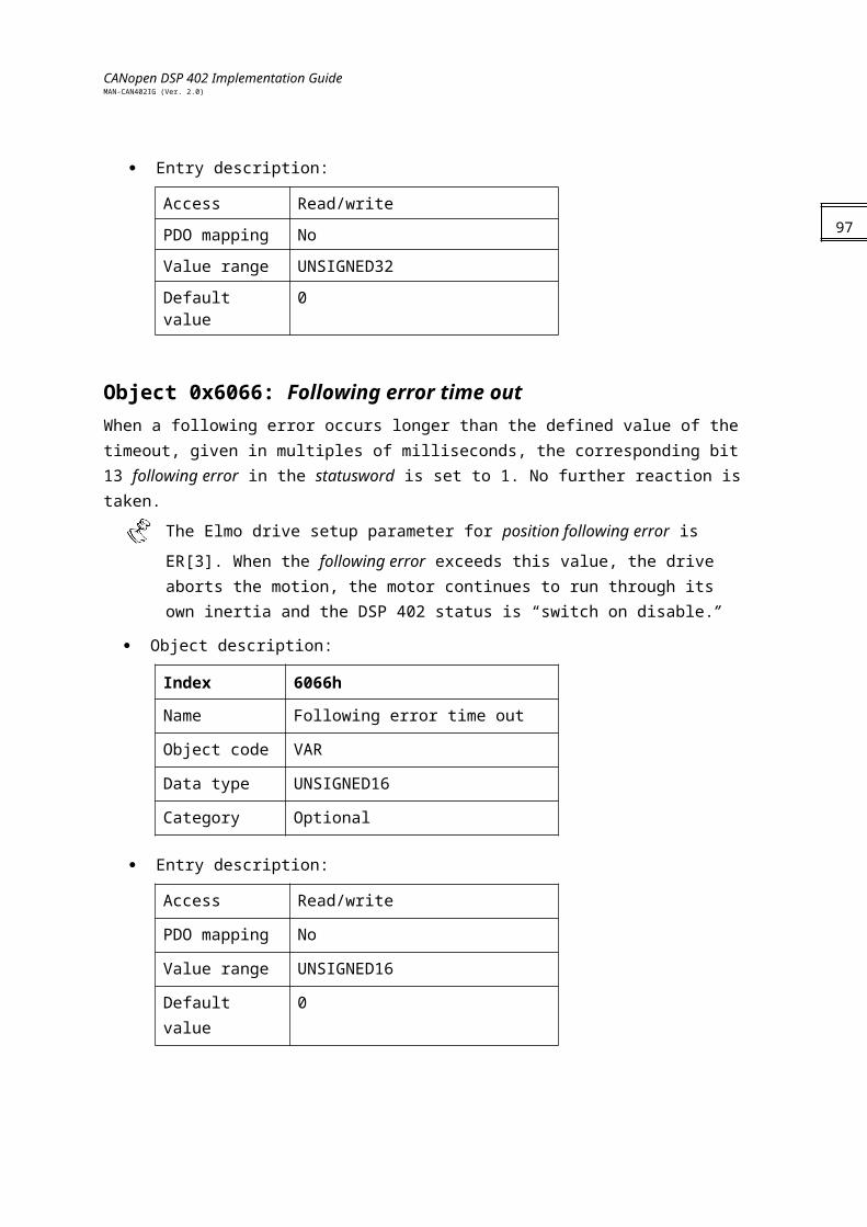
CANopen DSP 402 Implementation GuideMAN-CAN402IG (Ver. 2.0)
In Interpolated Position mode, the drive executes a time-synchronized motion path. The user specifies the value of the reference signal at an initial time, and at fixed-time intervals from then on (as in the following figure).
Figure 12: Interpolated Motion
In the figure, the time interval is set by the object 0x60c2, in milliseconds. The data records P0,P1,P2,… (object 0x60C1) to define the motion path data relating to the times
The motion path is synchronized to the CAN microsecond timer, as set and corrected by the SYNC-Time stamp mechanism. The user must specify the data records P0,P1,P2,…fast enough – at an average rate of at least one record per . The drive can store up to 64 records, so that the path may be programmed in bursts in order to relax the feeding real-time requirements.In order to enter IP mode, use the controlword (0x6040) to start the motor, and then use the modes of operation(0x6060) object to select IP mode.You can monitor the mode using the statusword (0x6041) and modes of operation display (0x6061).The interpolation sub-mode in object 0x60C0 determines the type of interpolation performed. The Elmo drive supports two types of interpolation:
Linear interpolation (default)
Cubic spline interpolationThe structure of the 0x60C1 object depends on the interpolation sub-modes. Refer to the definition of 0x60C1 to learn more about sub-mode switching.
Linear InterpolationLinear interpolation requires only the position specified in data record object 0x60C1. The structure of the position data is according to data type 0x41 (refer to the Elmo CANopen Implementation Guide). The velocity at each time point is calculated by finding the difference between the corresponding position and the position of the previous point, as in the following figure.
99
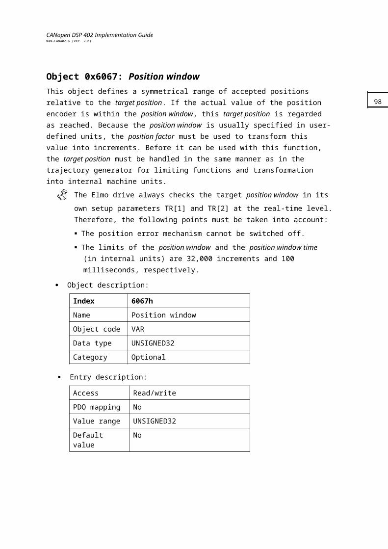
CANopen DSP 402 Implementation GuideMAN-CAN402IG (Ver. 2.0)
Figure 13: Linear IP
In the linear interpolation, two set points can be given in one message and thereby save on busload and real time requirements.
Spline InterpolationIn cubic spline interpolation, the user specifies both the position and the speed at each time point. The record data type is 0x44 (refer to the Elmo CANopen Implementation Guide). The drive constructs the motion path to be at the given time, at the given position, with the given speed, as in the following figure. Spline interpolation can yield a more accurate path specification with fewer time points, but it requires the care in constructing the speed data.
Figure 14: Spline IP
Motion SynchronizationThe IP mode enables the synchronized motion of multiple axes. The motions of several slave axes are synchronized if they all run IP, and they all being the IP at the same time. Synchronization can proceed continuously using the SYNC-Time stamp mechanism. In order to start several axes synchronously, map the controlword to a synchronous RPDO, and then use the mapped controlword to enable interpolation for all axes. Nothing will happen until the next SYNC. Then, all drives will enable interpolated motion at once, setting the SYNC arrival time as the “zero” time of the path specification.
100
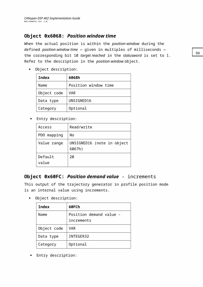
CANopen DSP 402 Implementation GuideMAN-CAN402IG (Ver. 2.0)
If the axes have been previously synchronized by SYNCs and Time stamps, the moving axes will be relatively synchronized to the precision of microseconds.
101

CANopen DSP 402 Implementation GuideMAN-CAN402IG (Ver. 2.0)
Chapter 13: Profiled Velocity6069h: Velocity sensor actual value
6060h: Velocity window
606Ah: Sensor selection code
606Bh: Velocity demand value
606Ch: Velocity actual value
606Dh: Velocity window
606Eh: Velocity window time
606Fh: Velocity threshold
6070h: Velocity threshold time
60FFh: Target velocity
General InformationProfile Velocity mode includes the following sub-functions:
Demand value input via trajectory generator
Velocity capture using the position sensor or velocity sensor
Velocity control function with the appropriate input and output signals
Monitoring of the profile velocity using a window function
Monitoring of the velocity actual value using a thresholdThe input parameters of the reference value generator are:
Profile velocity
Profile acceleration
Profile deceleration
Emergency stop
Motion profile typeThese parameters and the operation of the reference value generator are described in section Chapter 11:.The velocity controller calculates a torque variable. When a different target position arrives, it is executed immediately.
Notes:
A target velocity can be executed only in OPERATION ENABLED state. Otherwise, the process aborts with an emergency message.
The velocity, acceleration and deceleration are submitted to the limits according to the relevant limit range.
102
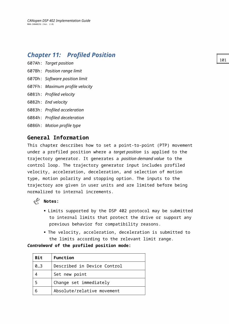
CANopen DSP 402 Implementation GuideMAN-CAN402IG (Ver. 2.0)
Controlword of the profiled velocity mode:
Bit Function
0…3 Described in Device Control
4… Reserved
7 Described in Device Control
8 Halt
9…15 Described in Device Control
14..15 Described in Device Control
Name Value Description
Halt 0 Execute the motion.
1 Stop axle.
Statusword of the profiled velocity mode:
Bit Function
0…9 Described in Device Control
10 Target reached
11 Described in Device Control
12 Speed
13 Maximum slippage (not implemented)
14…15 Described in Device Control
Name Value Description
Target reached 0 Halt = 0: Target velocity not (yet) reached.Halt = 1: Axle decelerates.
1 Halt = 0: Target velocity reached.Halt = 1: Velocity of axle is 0.
Speed 0 Speed not equal to 0.
1 Speed equals 0.
Max slippage error
0 Not implemented.
1
Objects
103
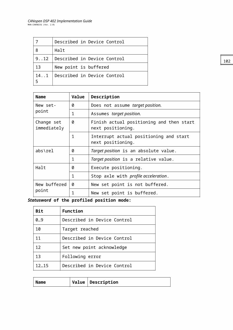
CANopen DSP 402 Implementation GuideMAN-CAN402IG (Ver. 2.0)
Object 0x6069: Velocity sensor actual value This object describes the value read from a velocity encoder, in increments/second. If the velocity sensor actual value is reflected by object 0x606C, it is scaled by position_factor_2 and by position_factor_1.
Object description:
Index 6069h
Name Velocity sensor actual value
Object code VAR
Data type INTEGER32
Category Mandatory
Entry description:
Access Read/Write
PDO mapping Yes
Value range INTEGER32
Default value 0
This value is not scaled with velocity factor 2.
Object 0x606A: Sensor selection code The source of the velocity actual value (object 0x606C) can be determined using the sensor selection code, which determines whether a differentiated position signal or the signal from a separate velocity sensor needs to be evaluated.
Object description:
Index 606Ah
Name Sensor selection code
Object code VAR
Data type INTEGER16
Category Optional
Entry description:
Access Read/write
PDO mapping No
Value range INTEGER16
Default value No
104
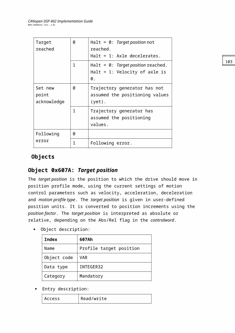
CANopen DSP 402 Implementation GuideMAN-CAN402IG (Ver. 2.0)
Data description:
Value Description
0000h Actual velocity value from position encoder
0001h Actual velocity value from velocity encoder
0002h…7FFFh Reserved
8000h…FFFFh Manufacturer specific
Object 0x606B: Velocity demand value
The value of the velocity command as reflected by the trajectory generator. This value is scaled by velocity_factor_1.
Object description:
Index 606Bh
Name Velocity demand value
Object code VAR
Data type INTEGER32
Category Mandatory
Entry description:
Access Read only
PDO mapping Yes
Value range INTEGER32
Default value No
105
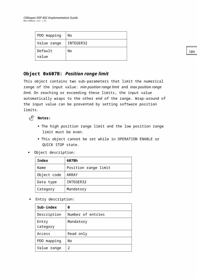
CANopen DSP 402 Implementation GuideMAN-CAN402IG (Ver. 2.0)
Object 0x606C: Velocity actual valueThis object is represented in velocity units and is coupled with the velocity used as input to the velocity controller. The object is taken from either the position sensor or the velocity sensor. In UM=5 (single position loop), this object reflects the load and the motor value; in UM=4 (dual loop), object 0x606A determines which sensor is reflected.
Object description:
Index 606Ch
Name Velocity actual value
Object code VAR
Data type INTEGER32
Category Mandatory
Entry description:
Access Read only
PDO mapping Yes
Value range INTEGER32
Default value No
Object 0x606D: Velocity windowThis object monitors whether the required process velocity has been achieved after an eventual acceleration or deceleration (braking) phase. It is given in velocity units.
Object description:
Index 606Dh
Name Velocity window
Object code VAR
Data type UNSIGNED16
Category Optional
Entry description:
Access Read/write
PDO mapping No
Value range UNSIGNED16
Default value No
106
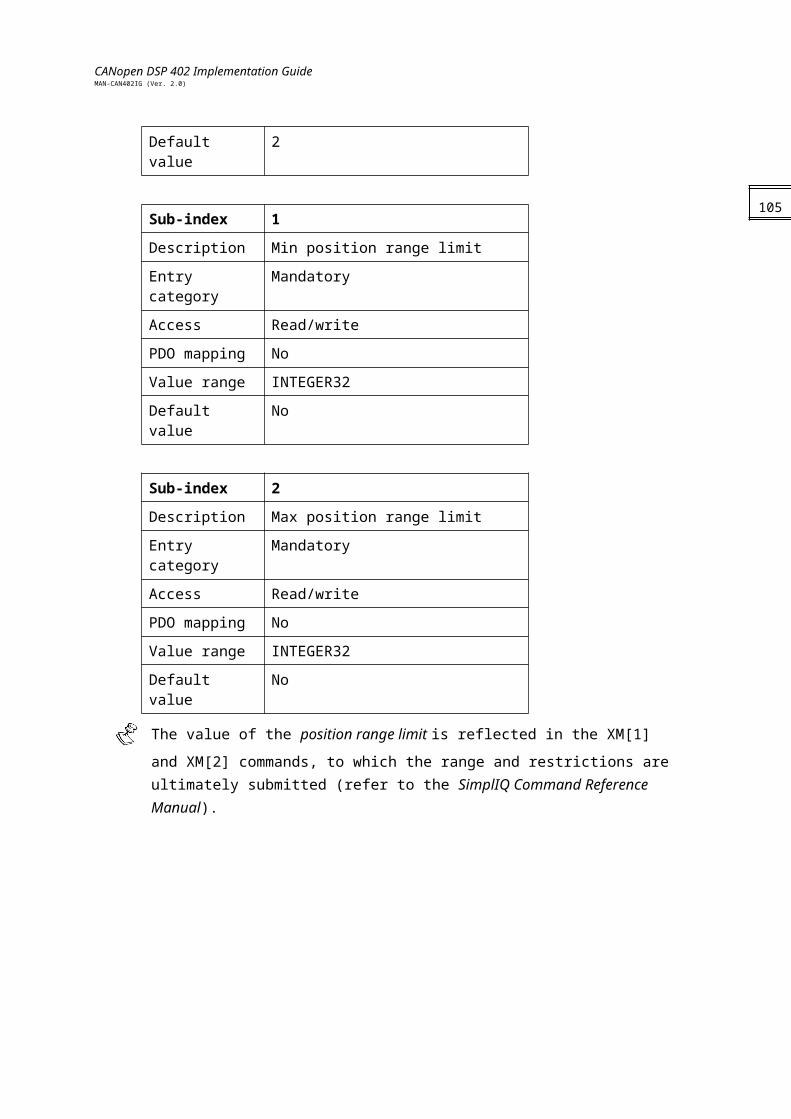
CANopen DSP 402 Implementation GuideMAN-CAN402IG (Ver. 2.0)
Object 0x606E: Velocity window time The corresponding bit 10 target reached is set in the statusword when the difference between the target velocity and the velocity actual value is within the velocity window longer than the velocity window time. The value of the velocity window time is given in multiples of milliseconds.
Object description:
Index 606Eh
Name Velocity window time
Object code VAR
Data type UNSIGNED16
Category Optional
Entry description:
Access Read/write
PDO mapping No
Value range UNSIGNED16
Default value 0
Object 0x606F: Velocity threshold As soon as the velocity actual value exceeds the velocity threshold longer than the velocity threshold time bit 12, velocity = 0, is reset in the statusword. Below this threshold, the bit is set and indicates that the axle is stationery. The value is given in velocity units.
Object description:
Index 606Fh
Name Velocity threshold
Object code VAR
Data type UNSIGNED16
Category Optional
Entry description:
Access Read/write
PDO mapping No
Value range UNSIGNED16
Default value No
107
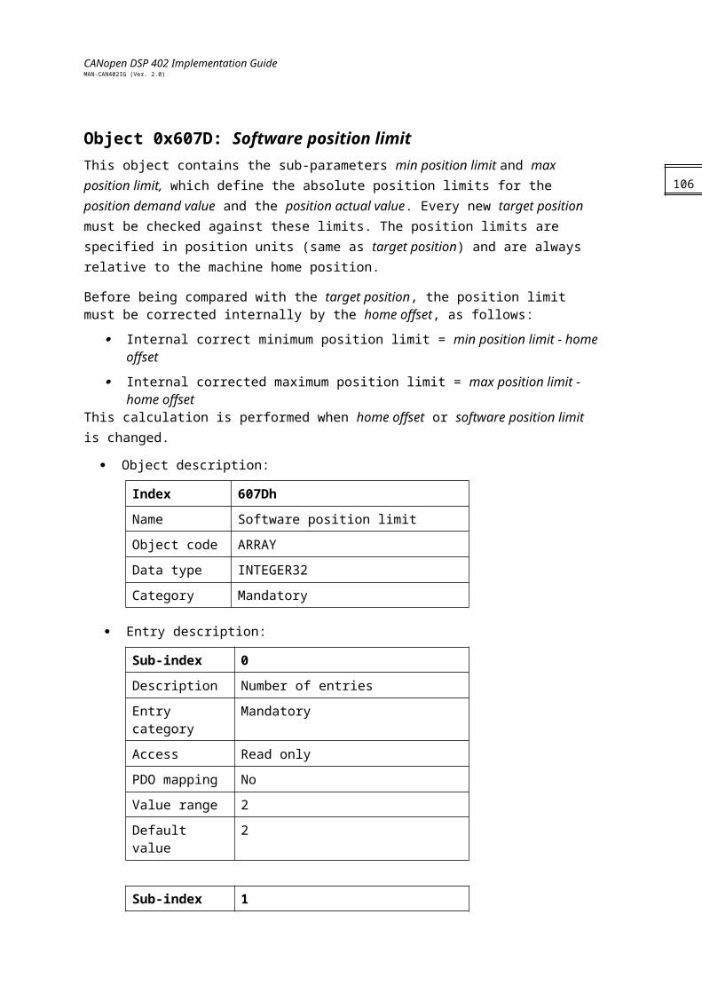
CANopen DSP 402 Implementation GuideMAN-CAN402IG (Ver. 2.0)
Object 0x6070: Velocity threshold time The velocity threshold time is given in multiples of milliseconds. See the description in object 0x606F.
Object description:
Index 6070h
Name Velocity threshold time
Object code VAR
Data type UNSIGNED16
Category Optional
Entry description:
Access Read/write
PDO mapping No
Value range UNSIGNED16
Default value No
Object 0x60FF: Target velocity The target velocity is the input for the trajectory generator. The value is given in velocity units.
Object description:
Index 60FFh
Name Target velocity
Object code VAR
Data type INTEGER32
Category Mandatory
Entry description:
Access Read/write
PDO mapping Yes
Value range INTEGER32
Default value No
108
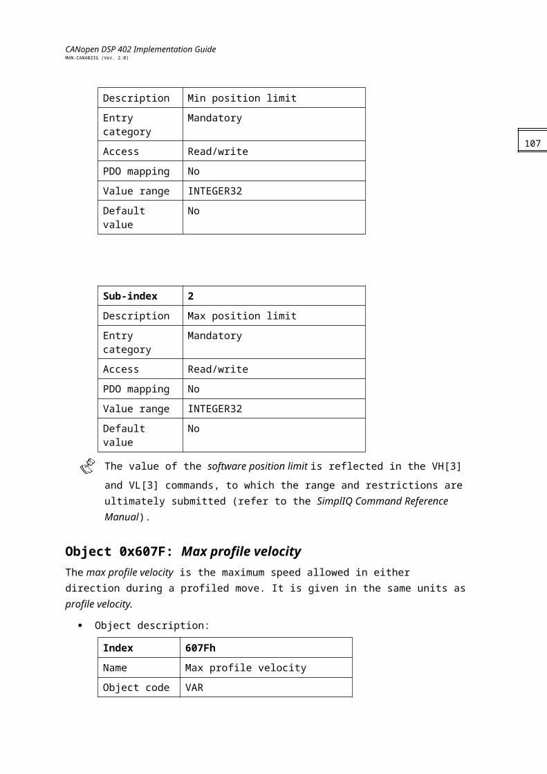
CANopen DSP 402 Implementation GuideMAN-CAN402IG (Ver. 2.0)
Chapter 14: Profiled Torque Mode6071h : Target torque 6072h : Max torque 6073h : Max current 6074h : Torque demand value 6075h : Motor rated current 6076h : Motor rated torque 6077h : Torque actual value 6078h : Current actual value 6087h : Torque slope 6088h : Torque profile type
General InformationThis chapter describes the profile torque mode. The profile torque mode allows a host (external) control system (i.e. closed-loop speed controller, open-loop transmission force controller) to transmit the target torque value, which is processed via the trajectory generator. In profile torque mode, torque slope and torque profile type parameters are required.Should the host control system switch the controlword bit 8 (halt) from 0 to 1, then the trajectory generator ramps its control output down to zero. Should the host control system switch the controlword bit 8 (halt) from 1 to 0, then the trajectory generator ramps its control output up to the target torque. In both cases the trajectory generator takes the torque slope and torque profile type into consideration.All definitions within this document refer to rotating motors. Linear motors require that all "torque" objects refer to a "force" instead. For the sake of simplicity, the objects are not duplicated and their names should not be modified. As an example, the linear motor target force must be transmitted using the target torque object. Refer to the object descriptions for additional information.
The SimplIQ drive deals only with the profile structure and not the control structure. For more information about the Torque\Current control loop please refer to the SimplIQ Software Manual.The torque control parameters, power stage parameters and motor parameters are defined as objects so that they can be handled (i.e. downloaded) in a standard way. Their detailed data content is manufacturer-specific.The torque demand, torque actual value, current actual value may be available to the user as parameters, if they are monitored.Elmo’s SimplIQ drives support Profile Torque mode when selected. When Profile Torque objects are set, some internal commands are affected. These internal commands remain even after another operating mode is chosen. The following list shows the objects that are affected, more information about these commands is available in the SimplIQ Command Reference manual:Max Torque [0x6072] : Set PL[1]Max Current [0x6073] : Set PL[1]Torque Demand Value [0x6074] : Reflect DV[1]Motor Rated Current [0x6075] : Set CL[1]
109
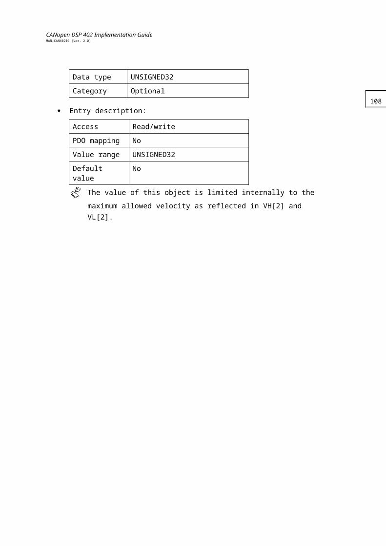
CANopen DSP 402 Implementation GuideMAN-CAN402IG (Ver. 2.0)
Torque Actual Value [0x6077] : Reflect IQCurrent Actual Value [0x6078] : Reflect IQ
Notes:
Because DSP402 defines all relevant torque and current as relative to rate values, motor current and motor torque are, herein, considered to be the same.The following objects imitate each other and the last value entered is valid:
0x6072, 0x6073 for reference.0x6077, 0x6078 for feedback.
Internal states
Controlword of profile torque mode
Bit Function
0…3 Described in Device Control
4…6 Reserved
7 Described in Device Control
8 Halt
9…15 Described in Device Control
Name Value Description
Halt 0 Execute the motion.
1 Stop axle.
110
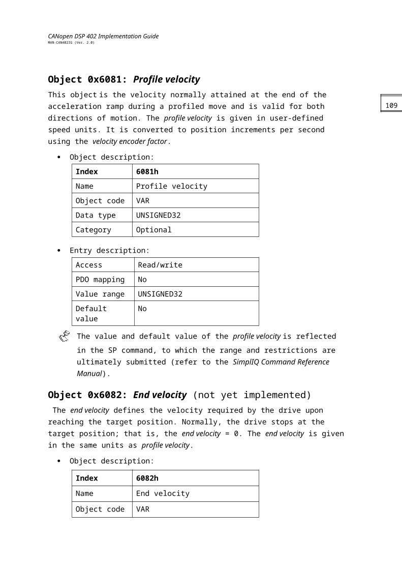
CANopen DSP 402 Implementation GuideMAN-CAN402IG (Ver. 2.0)
Statusword of the profiled velocity mode:
Bit Function
0…9 Described in Device Control
10 Target reached
11…13 Reserve
14…15 Described in Device Control
Name Value Description
Target reached
0 Target torque not (yet) reached.
1 Target torque reached.
Objects dictionary entries
Objects defined in other chapters6040h Controlword6041h Statusword
Objects description
Object 0x6071: Target torque This parameter is the input value for the torque controller in profile torque mode and the value is given per thousand of rated torque.
Object description:
Index 6071h
Name Target torque
Object code VAR
Data type INTEGER16
Category Mandatory
Entry description:
Access Read/write
PDO mapping Yes
Value range INTEGER16
Default value 0Example:
111
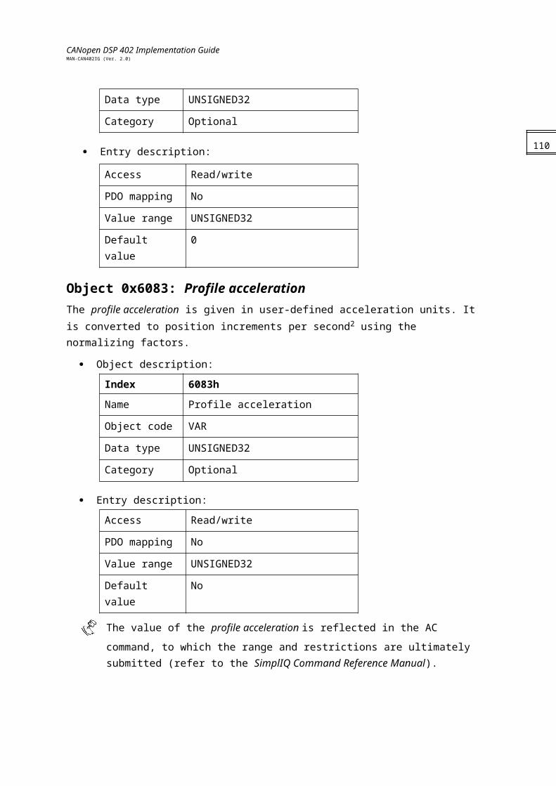
CANopen DSP 402 Implementation GuideMAN-CAN402IG (Ver. 2.0)
If a torque that is relative to current of 2 amps is needed, and object 0x6075 (Motor Rate Current) is 3200 mA,then [0x6071] = 2000 mA x 1000 / 3200 mA = 625This number means 62.5 % of Motor Rate Current.
Object 0x6072: Max torque This value represents the maximum permissible torque in the motor and is given per thousand of rated torque.
Object description:
Index 6072h
Name Max torque
Object code VAR
Data type INTEGER16
Category Mandatory
Entry description:
Access Read/write
PDO mapping No
Value range INTEGER16
Default value 0
Note : The behavior of this object is the same as 0x6073, because the current and the torque are proportional, and both of those objects (0x6072, 0x6073) are relative to the torque (or current).This object sets PL[1].
Object 0x6073: Max Current This value represents the maximum permissible torque creating current in the motor and is given per thousand of rated current.
Object description:
Index 6073h
Name Max current
Object code VAR
Data type INTEGER16
Category Mandatory
Entry description:
112
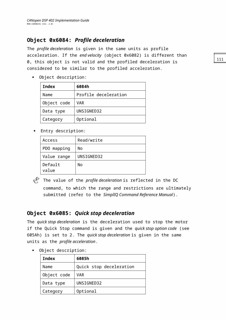
CANopen DSP 402 Implementation GuideMAN-CAN402IG (Ver. 2.0)
Access Read/write
PDO mapping No
Value range INTEGER16
Default value 0
Note: The value in 6073h (which is in mA) is entered in PL[1] after it is converted to Amperes. For example:
If we want PL[1] to be 4 Amps,and in [0x6075] is set to 3200 mAthen [0x6073] = 4000 * 1000 / 3200 = 1250
Object 0x6074: Torque Demand value This value represents the maximum permissible torque creating current in the motor and is given in units of per thousand of rated current.
Object description:
Index 6074h
Name Max current
Object code VAR
Data type INTEGER16
Category Mandatory
Entry description:
Access Read
PDO mapping No
Value range INTEGER16
Default value 0
Note: This Object reflects DV[1]
Object 0x6075: Motor Rate Current This value is taken from the motor nameplate and is entered in multiples of milliamp. Depending on the motor and drive technology this current may be either DC, peak or rms (root-mean-square) current. All relative current data refers to this value.
Object description:
Index 6075h
Name Motor Rate Current
Object code VAR
Data type UNSIGNED32
113
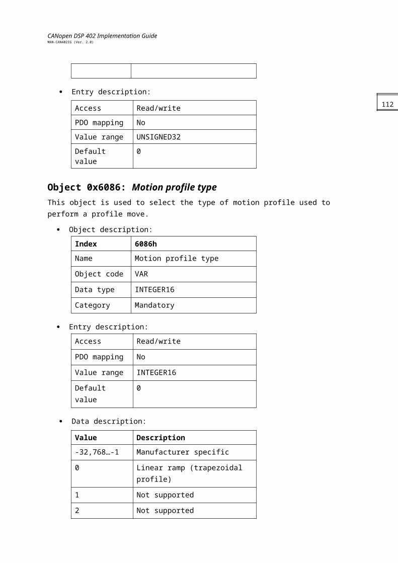
CANopen DSP 402 Implementation GuideMAN-CAN402IG (Ver. 2.0)
Category Mandatory
Entry description:
Access Read/write
PDO mapping No
Value range UNSIGNED32
Default value 0
Note: This value of 6075h is set to CL[1] after it is converted to Amperes.
Object 0x6076: Motor Rate Torque This value is taken from the motor name plate and is entered as a multiple of mNm (mill wtonmeter). All relative torque data refer to this value.For linear motors, the object name is not changed, but the motor rated force value must be entered as a multiple of mN (mill Newton)..
Object description:
Index 6076h
Name Motor Rate Torque
Object code VAR
Data type UNSIGNED32
Category Mandatory
Entry description:
Access Read/write
PDO mapping No
Value range UNSIGNED32
Default value 0
Object 0x6077: Torque Actual value The torque actual value corresponds to the instantaneous torque in the drive motor. The value is given in units of per thousand of rated torque.
Object description:
Index 6077h
Name Torque Actual value
114
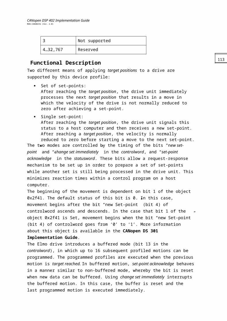
CANopen DSP 402 Implementation GuideMAN-CAN402IG (Ver. 2.0)
Object code VAR
Data type INTEGER16
Category Mandatory
Entry description:
Access Read
PDO mapping Yes
Value range INTEGER16
Default value 0
Note: This Object reflects the Actual Current ( IQ )
Object 0x6078: Current Actual value The current actual value refers to the instantaneous current in the drive motor. The value is given in units of per thousand of rated current.
Object description:
Index 6078h
Name Current Actual value
Object code VAR
Data type INTEGER16
Category Mandatory
Entry description:
Access Read
PDO mapping Yes
Value range INTEGER16
Default value 0
Note: This Object reflects the Actual Current ( IQ)
Object 0x6087: Torque slopeThis parameter describes the rate of change of torque in units of per thousand of rated torque per second.
Object description:
115
CANopen DSP 402 Implementation GuideMAN-CAN402IG (Ver. 2.0)
Index 6087h
Name Torque Slope
Object code VAR
Data type UNSIGNED32
Category Mandatory
Entry description:
Access Read/write
PDO mapping Yes
Value range UNSIGNED32
Default value 0Note: If a user submits a value that is greater than of the maximum admissible value of this
object, then the drive loads the maximum possible value, without issuing a receive error message.
Object 0x6088: Torque profile typeThe torque profile type is used to select the type of torque profile used to perform a torque change.
Object description:
Index 6078h
Name Torque profile type
Object code VAR
Data type INTEGER16
Category Mandatory
Entry description:
Access Read/Write
PDO mapping No
Value range INTEGER16
Default value 0
Data Description:
Value Description
0 Linear ramp (trapezoidal profile)Note: The SimplIQ family of digital servo drives works with option 0 (Linear ramp) only.
116
CANopen DSP 402 Implementation GuideMAN-CAN402IG (Ver. 2.0)
Appendix A: Dimension Index TablePhysical Dimension Unit Dimension Index
None - 0x00
Way/length m 0x01
Area m 0xA0
Volume m 0xA1
Time s 0xA2
min 0x47
h 0x48
d 0x49
y 0x4A
Power W 0x24
Revolutions/time rev / s 0xA3
rev / min 0xA4
rev / h 0xA5
Angle rad 0x10
s 0x43
m 0x42
º 0x41
Velocity m / s 0xA6
m / min 0xA7
m / h 0xA8
Torque N / m 0xA9
Temperature K 0x05
º C 0x2D
F 0xAA
Voltage V 0x26
Current A 0x04
Ratio % 0xAB
Frequency Hz 0x20
Steps steps 0xAC
Steps / revolution steps / rev 0xAD
117

CANopen DSP 402 Implementation GuideMAN-CAN402IG (Ver. 2.0)
Appendix B: Notation Index TablePrefix Factor Symbol Notation Index
unused - - 0x13…0x7Fexa 10 E 0x12
- 10 - 0x11
- 10 - 0x10
peta 10 P 0x0F
- 10 - 0x0E
- 10 - 0x0D
tera 10 T 0x0C
- 10 - 0x0B
- 10 - 0x0A
giga 10 G 0x09
- 10 - 0x08
- 10 - 0x07
mega 10 M 0x06
- 10 - 0x05
- 10 - 0x04
kilo 10 k 0x03
hecto 10 h 0x02
deca 10 da 0x01
- 10 0x00
deci 10 d 0xFF
centi 10 c 0xFE
milli 10 m 0xFD
- 10 - 0xFC
- 10 - 0xFB
micro 10 0xFA
- 10 - 0xF9
- 10 - 0xF8
nano 10 n 0xF7
- 10 - 0xF6
- 10 - 0xF5
pico 10 p 0xF4
- 10 - 0xF3
118
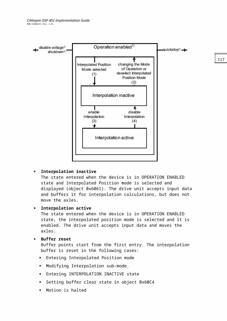
CANopen DSP 402 Implementation GuideMAN-CAN402IG (Ver. 2.0)
- 10 - 0xF2
femto 10 f 0xF1
- 10 - 0xF0
- 10 - 0xEF
atto 10 a 0xEE
unused - - 0xED…0x80
119