Embed Size (px)
Citation preview

Jul 17 2009
Service Manual
Finisher, Sorter, DeliveryTrayBooklet Finisher-C1

ApplicationThis manual has been issued by Canon Inc. for qualified persons to learn technical theory, installation, maintenance, and repair
of products. This manual covers all localities where the products are sold. For this reason, there may be information in this
manual that does not apply to your locality.
CorrectionsThis manual may contain technical inaccuracies or typographical errors due to improvements or changes in products. When
changes occur in applicable products or in the contents of this manual, Canon will release technical information as the need
arises. In the event of major changes in the contents of this manual over a long or short period, Canon will issue a new edition
of this manual.
The following paragraph does not apply to any countries where such provisions are inconsistent with local law.
TrademarksThe product names and company names used in this manual are the registered trademarks of the individual companies.
CopyrightThis manual is copyrighted with all rights reserved. Under the copyright laws, this manual may not be copied, reproduced or
translated into another language, in whole or in part, without the written consent of Canon Inc.
COPYRIGHT © 2001 CANON INC.Printed in Japan
CautionUse of this manual should be strictly supervised to avoid disclosure of confidential information.

Introduction
Symbols UsedThis documentation uses the following symbols to indicate special information:
Symbol Description
Indicates an item of a non-specific nature, possibly classified as Note, Caution, or Warning.
Indicates an item requiring care to avoid electric shocks.
Indicates an item requiring care to avoid combustion (fire).
Indicates an item prohibiting disassembly to avoid electric shocks or problems.
Indicates an item requiring disconnection of the power plug from the electric outlet.
Indicates an item intended to provide notes assisting the understanding of the topic in question.
Indicates an item of reference assisting the understanding of the topic in question.
Provides a description of a service mode.
Provides a description of the nature of an error indication.
Memo
REF.

Introduction
The following rules apply throughout this Service Manual:1. Each chapter contains sections explaining the purpose of specific functions and the relationship between electrical and mechanical systems with refer-
ence to the timing of operation.In the diagrams, represents the path of mechanical drive; where a signal name accompanies the symbol , the arrow indicates thedirection of the electric signal.The expression "turn on the power" means flipping on the power switch, closing the front door, and closing the delivery unit door, which results insupplying the machine with power.
2. In the digital circuits, '1'is used to indicate that the voltage level of a given signal is "High", while '0' is used to indicate "Low".(The voltage value, how-ever, differs from circuit to circuit.) In addition, the asterisk (*) as in "DRMD*" indicates that the DRMD signal goes on when '0'.In practically all cases, the internal mechanisms of a microprocessor cannot be checked in the field. Therefore, the operations of the microprocessorsused in the machines are not discussed: they are explained in terms of from sensors to the input of the DC controller PCB and from the output of theDC controller PCB to the loads.
The descriptions in this Service Manual are subject to change without notice for product improvement or other purposes, and major changes will be com-municated in the form of Service Information bulletins.All service persons are expected to have a good understanding of the contents of this Service Manual and all relevant Service Information bulletins and beable to identify and isolate faults in the machine."

Contents
Contents
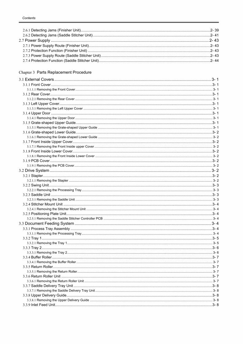
Chapter 1 Specifications
1.1 Product Specifications ................................................................................................................................1- 11.1.1 Finisher Unit ............................................................................................................................................................1- 11.1.2 Saddle Sticher Unit..................................................................................................................................................1- 3
1.2 Names of Parts ...........................................................................................................................................1- 51.2.1 External View...........................................................................................................................................................1- 51.2.2 Cross Section (Finisher Unit)...................................................................................................................................1- 51.2.3 Cross Section (Saddle Stitcher Unit) .......................................................................................................................1- 6
Chapter 2 Functions
2.1 Basic Operation ..........................................................................................................................................2- 12.1.1 Basic Operation (Finisher Unit) ...............................................................................................................................2- 12.1.2 Overview of the Electrical Circuitry (Finisher Unit) ..................................................................................................2- 12.1.3 Basic Operation (Saddle Stitcher Unit) ....................................................................................................................2- 22.1.4 Overview of the Electrical Circuitry (Saddle Stitcher Unit).......................................................................................2- 2
2.2 Feed Drive System .....................................................................................................................................2- 32.2.1 Overview..................................................................................................................................................................2- 32.2.2 Constraction of the Control System (Finisher Unit) .................................................................................................2- 32.2.3 Paper Delivery Path (Finisher Unit) .........................................................................................................................2- 52.2.4 Constraction of the Control System (Saddle Stitcher Unit)......................................................................................2- 82.2.5 Paper Delivery Path (Saddle Stitcher Unit) .............................................................................................................2- 92.2.6 Controlling the Change of the Gear.......................................................................................................................2- 102.2.7 Basic Operation (Saddle Stitcher Unit) ..................................................................................................................2- 112.2.8 Controlling the Inlet Flappers.................................................................................................................................2- 142.2.9 Controlling the Movement of Sheets .....................................................................................................................2- 172.2.10 Controlling the Aligning the Sheets......................................................................................................................2- 182.2.11 Controlling the Phase of the Crescent Roller.......................................................................................................2- 202.2.12 Overview of Folding Operation ............................................................................................................................2- 222.2.13 Controlling the Movement of Stacks ....................................................................................................................2- 222.2.14 Folding a Stack ....................................................................................................................................................2- 232.2.15 Double Folding a Stack........................................................................................................................................2- 25
2.3 Intermediate Process Tray Assembly .......................................................................................................2- 262.3.1 Stack Job Offset ....................................................................................................................................................2- 262.3.2 Processing Tray Paper Stacking Operation ..........................................................................................................2- 272.3.3 Offset Operation ....................................................................................................................................................2- 282.3.4 Rear End Assist Operation ....................................................................................................................................2- 282.3.5 Stack Delivery Operation.......................................................................................................................................2- 292.3.6 Swing Height Detection Control.............................................................................................................................2- 29
2.4 Staple Operation.......................................................................................................................................2- 302.4.1 Overview................................................................................................................................................................2- 302.4.2 Stapler Unit............................................................................................................................................................2- 312.4.3 Shifting the Stapler Unit.........................................................................................................................................2- 312.4.4 Stapling Operation................................................................................................................................................. 2- 332.4.5 Stitcher Unit ...........................................................................................................................................................2- 362.4.6 Stitching Operation ................................................................................................................................................2- 37
2.5 Stack Tray Operation................................................................................................................................2- 372.5.1 Tray Operation.......................................................................................................................................................2- 372.5.2 Shutter Operation ..................................................................................................................................................2- 39
2.6 Detecting Jams.........................................................................................................................................2- 39
Contents
2.6.1 Detecting Jams (Finisher Unit)...............................................................................................................................2- 392.6.2 Detecting Jams (Saddle Stitcher Unit) ...................................................................................................................2- 41
2.7 Power Supply ........................................................................................................................................... 2- 432.7.1 Power Supply Route (Finisher Unit).......................................................................................................................2- 432.7.2 Protection Function (Finisher Unit) ........................................................................................................................2- 432.7.3 Power Supply Route (Saddle Stitcher Unit) ...........................................................................................................2- 432.7.4 Protection Function (Saddle Stitcher Unit).............................................................................................................2- 44
Chapter 3 Parts Replacement Procedure
3.1 External Covers .......................................................................................................................................... 3- 13.1.1 Front Cover ..............................................................................................................................................................3- 1
3.1.1.1 Removing the Front Cover....................................................................................................................................................... 3- 13.1.2 Rear Cover...............................................................................................................................................................3- 1
3.1.2.1 Removing the Rear Cover ....................................................................................................................................................... 3- 13.1.3 Left Upper Cover......................................................................................................................................................3- 1
3.1.3.1 Removing the Left Upper Cover .............................................................................................................................................. 3- 13.1.4 Upper Door ..............................................................................................................................................................3- 1
3.1.4.1 Removing the Upper Door ....................................................................................................................................................... 3- 13.1.5 Grate-shaped Upper Guide......................................................................................................................................3- 1
3.1.5.1 Removing the Grate-shaped Upper Guide .............................................................................................................................. 3- 13.1.6 Grate-shaped Lower Guide......................................................................................................................................3- 2
3.1.6.1 Removing the Grate-shaped Lower Guide .............................................................................................................................. 3- 23.1.7 Front Inside Upper Cover.........................................................................................................................................3- 2
3.1.7.1 Removing the Front Inside upper Cover .................................................................................................................................. 3- 23.1.8 Front Inside Lower Cover.........................................................................................................................................3- 2
3.1.8.1 Removing the Front Inside Lower Cover ................................................................................................................................. 3- 23.1.9 PCB Cover ...............................................................................................................................................................3- 2
3.1.9.1 Removing the PCB Cover........................................................................................................................................................ 3- 23.2 Drive System .............................................................................................................................................. 3- 2
3.2.1 Stapler......................................................................................................................................................................3- 23.2.1.1 Removing the Stapler .............................................................................................................................................................. 3- 2
3.2.2 Swing Unit................................................................................................................................................................3- 33.2.2.1 Removing the Processing Tray................................................................................................................................................ 3- 3
3.2.3 Saddle Unit ..............................................................................................................................................................3- 33.2.3.1 Removing the Saddle Unit ....................................................................................................................................................... 3- 3
3.2.4 Stitcher Mount Unit ..................................................................................................................................................3- 43.2.4.1 Removing the Stitcher Mount Unit ........................................................................................................................................... 3- 4
3.2.5 Positioning Plate Unit...............................................................................................................................................3- 43.2.5.1 Removing the Saddle Stitcher Controller PCB ........................................................................................................................ 3- 4
3.3 Document Feeding System ........................................................................................................................ 3- 43.3.1 Process Tray Assembly ...........................................................................................................................................3- 4
3.3.1.1 Removing the Processing Tray................................................................................................................................................ 3- 43.3.2 Tray 1.......................................................................................................................................................................3- 5
3.3.2.1 Removing the Tray 1................................................................................................................................................................ 3- 53.3.3 Tray 2.......................................................................................................................................................................3- 6
3.3.3.1 Removing the Tray 2................................................................................................................................................................ 3- 63.3.4 Buffer Roller .............................................................................................................................................................3- 7
3.3.4.1 Removing the Buffer Roller...................................................................................................................................................... 3- 73.3.5 Return Roller............................................................................................................................................................3- 7
3.3.5.1 Removing the Return Roller..................................................................................................................................................... 3- 73.3.6 Return Roller Unit ....................................................................................................................................................3- 7
3.3.6.1 Removing the Return Roller Unit ............................................................................................................................................. 3- 73.3.7 Saddle Delivery Tray Unit ........................................................................................................................................3- 8
3.3.7.1 Removing the Saddle Delivery Tray Unit ................................................................................................................................. 3- 83.3.8 Upper Delivery Guide...............................................................................................................................................3- 8
3.3.8.1 Removing the Upper Delivery Guide ....................................................................................................................................... 3- 83.3.9 Inlet Feed Unit..........................................................................................................................................................3- 8
Contents
3.3.9.1 Removing the Inlet Feed Unit .................................................................................................................................................. 3- 83.3.10 Paper Folding Roller ..............................................................................................................................................3- 9
3.3.10.1 Removing the Paper Folding Roller ....................................................................................................................................... 3- 93.3.11 No.1 Flapper ........................................................................................................................................................3- 10
3.3.11.1 Removing the No.1 Flappers ............................................................................................................................................... 3- 103.3.12 No.2 Flapper ........................................................................................................................................................3- 10
3.3.12.1 Removing the No.2 Flappers ............................................................................................................................................... 3- 103.4 Electrical System ......................................................................................................................................3- 10
3.4.1 Finisher Controller PCB.........................................................................................................................................3- 103.4.1.1 Finisher Controller PCB ......................................................................................................................................................... 3- 10
3.4.2 Static Charge Eliminator 1.....................................................................................................................................3- 113.4.2.1 Removing the Swing Unit Static Charge Eliminator............................................................................................................... 3- 11
3.4.3 Static Charge Eliminator 2.....................................................................................................................................3- 113.4.3.1 Removing the Inlet Static Charge Eliminator ......................................................................................................................... 3- 11
3.4.4 Saddle Stitcher Controller PCB .............................................................................................................................3- 113.4.4.1 Removing the PCB Cover...................................................................................................................................................... 3- 113.4.4.2 Removing the Saddle Stitcher Controller PCB ...................................................................................................................... 3- 12
Chapter 4 Maintenance
4.1 User Maintenance ......................................................................................................................................4- 14.1.1 User Maintenance (Finisher Unit) ............................................................................................................................4- 14.1.2 User Maintenance (Saddle Stitcher Unit) ................................................................................................................4- 1
4.2 Maintenance and Inspection.......................................................................................................................4- 14.2.1 Periodically Replaced Parts.....................................................................................................................................4- 1
4.2.1.1 Periodically Replaced Parts (Finisher Unit) ............................................................................................................................. 4- 14.2.1.2 Periodically Replaced Parts (Saddle Stitcher Unit) .................................................................................................................. 4- 1
4.2.2 Durables ..................................................................................................................................................................4- 14.2.2.1 Durables (Finisher Unit) ........................................................................................................................................................... 4- 14.2.2.2 Durables (Saddle Stitcher Unit) ............................................................................................................................................... 4- 2
4.2.3 Periodical Servicing .................................................................................................................................................4- 24.2.3.1 Periodical Servicing (Finisher Unit) .......................................................................................................................................... 4- 24.2.3.2 Periodical Servicing (Saddle Stitcher Unit) .............................................................................................................................. 4- 2
4.3 Adjustment..................................................................................................................................................4- 34.3.1 Basic Adjustment.....................................................................................................................................................4- 3
4.3.1.1 Upward Curl Mode ................................................................................................................................................................... 4- 34.3.1.2 Special Curl Mode.................................................................................................................................................................... 4- 34.3.1.3 Heavy Paper Upward Curl Mode ............................................................................................................................................. 4- 34.3.1.4 Saddle Delivery Tray Limitless Mode ...................................................................................................................................... 4- 44.3.1.5 1-sheet Shift/Sort Mode ........................................................................................................................................................... 4- 44.3.1.6 Heavy Sack Prohibition Mode.................................................................................................................................................. 4- 44.3.1.7 Tray Operation Test Mode ....................................................................................................................................................... 4- 44.3.1.8 Adjusting the Bias Line of Saddele Delivery Paper.................................................................................................................. 4- 4
4.3.2 Adjustment at Time of Parts Replacement ..............................................................................................................4- 64.3.2.1 Adjusting the Alignment Position ............................................................................................................................................. 4- 64.3.2.2 Adjusting the Staple Position ................................................................................................................................................... 4- 64.3.2.3 Adjusting the Folding Position.................................................................................................................................................. 4- 64.3.2.4 Adjusting the Stitching Position................................................................................................................................................ 4- 64.3.2.5 Adjusting the Stitcher Unit........................................................................................................................................................ 4- 7
4.4 Troubleshooting..........................................................................................................................................4- 94.4.1 Error Code ...............................................................................................................................................................4- 9
4.4.1.1 E503;Saddle stitcher unit communication error ....................................................................................................................... 4- 94.4.1.2 E514;Rear end assist motor error............................................................................................................................................ 4- 94.4.1.3 E519;Gear change motor error ................................................................................................................................................ 4- 94.4.1.4 E530;Front aligning plate motor error ...................................................................................................................................... 4- 94.4.1.5 E531;Staple motor error........................................................................................................................................................... 4- 94.4.1.6 E532;Stapler shift motor error.................................................................................................................................................. 4- 94.4.1.7 E535;Swing motor error ......................................................................................................................................................... 4- 104.4.1.8 E537;Rear aligning plate motor error..................................................................................................................................... 4- 10
Contents
4.4.1.9 E540;Tray 1 shift motor error ................................................................................................................................................. 4- 104.4.1.10 E542;Tray 2 shift motor error ............................................................................................................................................... 4- 104.4.1.11 E584;Shutter malfunction..................................................................................................................................................... 4- 104.4.1.12 E5F0;Paper positioning plate motor error ............................................................................................................................ 4- 104.4.1.13 E5F1;Paper folding motor error............................................................................................................................................ 4- 114.4.1.14 E5F2;Guide motor error ....................................................................................................................................................... 4- 114.4.1.15 E5F3;Aligning motor error .................................................................................................................................................... 4- 114.4.1.16 E5F4;Stitcher (rear) error ..................................................................................................................................................... 4- 114.4.1.17 E5F5;Stitcher (front) error .................................................................................................................................................... 4- 114.4.1.18 E5F6;Paper pushing plate motor error................................................................................................................................. 4- 114.4.1.19 E5F8;Sensor connector ....................................................................................................................................................... 4- 114.4.1.20 E5F9;Micro switch error ....................................................................................................................................................... 4- 12
4.5 Outline of Electrical Components ............................................................................................................. 4- 124.5.1 Sensors (Finisher Unit) ..........................................................................................................................................4- 124.5.2 Microswitches (Finisher Unit).................................................................................................................................4- 144.5.3 Solenoids (Finisher Unit)........................................................................................................................................4- 154.5.4 Motors (Finisher Unit) ............................................................................................................................................4- 164.5.5 Clutches (Finisher Unit) .........................................................................................................................................4- 174.5.6 PCBs (Finisher Unit) ..............................................................................................................................................4- 184.5.7 Sensors (Saddle Stitcher Unit)...............................................................................................................................4- 194.5.8 Microswitches (Saddle Stitcher Unit) .....................................................................................................................4- 204.5.9 Motors (Saddle Stitcher Unit).................................................................................................................................4- 214.5.10 Solenoids (Saddle Stitchwe Unit).........................................................................................................................4- 224.5.11 PCBs (Saddle Stitcher Unit).................................................................................................................................4- 23
4.6 Variable Resistors (VR), Light-Emitting Diodes (LED), and Check Pins by PCB..................................... 4- 234.6.1 Overview................................................................................................................................................................4- 234.6.2 Finisher Controller PCB .........................................................................................................................................4- 244.6.3 Saddle Stitcher Controller PCB..............................................................................................................................4- 24
4.7 Upgrading................................................................................................................................................. 4- 244.7.1 Upgrading (Finisher Unit).......................................................................................................................................4- 244.7.2 Upgrading (Saddle Stitcher Unit) ...........................................................................................................................4- 31
4.8 Service Tools............................................................................................................................................ 4- 394.8.1 Solvents and Oils ...................................................................................................................................................4- 39
Chapter 5 Error Code
5.1 Overview .................................................................................................................................................... 5- 15.1.1 Overview..................................................................................................................................................................5- 1
5.2 User Error Code ......................................................................................................................................... 5- 15.2.1 Staple is absent .......................................................................................................................................................5- 15.2.2 Stapler safety protection function activated .............................................................................................................5- 15.2.3 Stack tray overstacking............................................................................................................................................5- 15.2.4 Stapler staple jam ....................................................................................................................................................5- 25.2.5 Staple is absent (Saddle Stitcher Unit) ....................................................................................................................5- 25.2.6 Mixed paper sizes (Saddle Stitcher Unit).................................................................................................................5- 25.2.7 Stack exceeded (Saddle Stitcher Unit) ....................................................................................................................5- 25.2.8 Stitching capacity error (Saddle Stitcher Unit) .........................................................................................................5- 2
5.3 Service Error Code..................................................................................................................................... 5- 35.3.1 E500.........................................................................................................................................................................5- 35.3.2 E503.........................................................................................................................................................................5- 35.3.3 E505.........................................................................................................................................................................5- 35.3.4 E514.........................................................................................................................................................................5- 35.3.5 E519.........................................................................................................................................................................5- 35.3.6 E530.........................................................................................................................................................................5- 45.3.7 E531.........................................................................................................................................................................5- 45.3.8 E532.........................................................................................................................................................................5- 45.3.9 E535.........................................................................................................................................................................5- 4

Contents
5.3.10 E537 ......................................................................................................................................................................5- 55.3.11 E540 ......................................................................................................................................................................5- 55.3.12 E542 ......................................................................................................................................................................5- 55.3.13 E584 ......................................................................................................................................................................5- 55.3.14 E5F0 ......................................................................................................................................................................5- 65.3.15 E5F1 ......................................................................................................................................................................5- 65.3.16 E5F2 ......................................................................................................................................................................5- 65.3.17 E5F3 ......................................................................................................................................................................5- 65.3.18 E5F4 ......................................................................................................................................................................5- 75.3.19 E5F5 ......................................................................................................................................................................5- 75.3.20 E5F6 ......................................................................................................................................................................5- 75.3.21 E5F8 ......................................................................................................................................................................5- 85.3.22 E5F9 ......................................................................................................................................................................5- 85.3.23 Temporary Functional Limit ...................................................................................................................................5- 8

Contents

Chapter 1 Specifications


Contents
Contents
1.1 Product Specifications....................................................................................................................................................1-11.1.1 Finisher Unit ................................................................................................................................................................................ 1-11.1.2 Saddle Sticher Unit ...................................................................................................................................................................... 1-3
1.2 Names of Parts ...............................................................................................................................................................1-51.2.1 External View .............................................................................................................................................................................. 1-51.2.2 Cross Section (Finisher Unit)....................................................................................................................................................... 1-51.2.3 Cross Section (Saddle Stitcher Unit) ........................................................................................................................................... 1-6

Chapter 1
1-1
1.1 Product Specifications
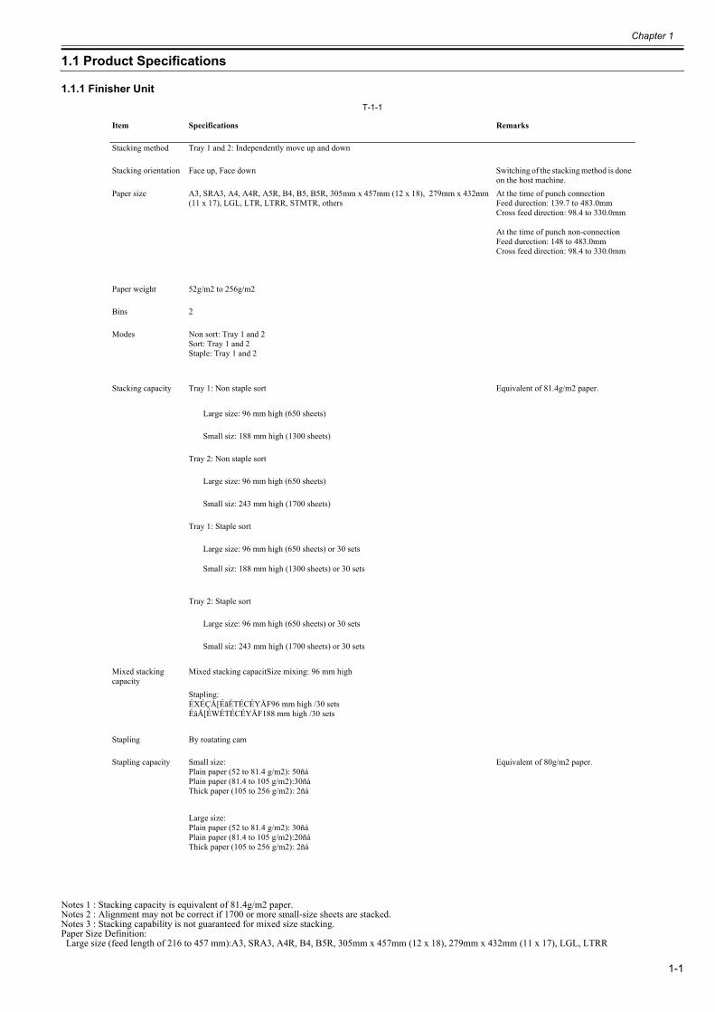
1.1.1 Finisher Unit0023-6342
T-1-1
Notes 1 : Stacking capacity is equivalent of 81.4g/m2 paper.Notes 2 : Alignment may not be correct if 1700 or more small-size sheets are stacked.Notes 3 : Stacking capability is not guaranteed for mixed size stacking.Paper Size Definition: Large size (feed length of 216 to 457 mm):A3, SRA3, A4R, B4, B5R, 305mm x 457mm (12 x 18), 279mm x 432mm (11 x 17), LGL, LTRR
Item Specifications Remarks
Stacking method Tray 1 and 2: Independently move up and down
Stacking orientation Face up, Face down Switching of the stacking method is done on the host machine.
Paper size A3, SRA3, A4, A4R, A5R, B4, B5, B5R, 305mm x 457mm (12 x 18), 279mm x 432mm (11 x 17), LGL, LTR, LTRR, STMTR, others
At the time of punch connectionFeed durection: 139.7 to 483.0mmCross feed direction: 98.4 to 330.0mm
At the time of punch non-connectionFeed durection: 148 to 483.0mmCross feed direction: 98.4 to 330.0mm
Paper weight 52g/m2 to 256g/m2
Bins 2
Modes Non sort: Tray 1 and 2Sort: Tray 1 and 2Staple: Tray 1 and 2
Stacking capacity Tray 1: Non staple sort Equivalent of 81.4g/m2 paper.
Large size: 96 mm high (650 sheets)
Small siz: 188 mm high (1300 sheets)
Tray 2: Non staple sort
Large size: 96 mm high (650 sheets)
Small siz: 243 mm high (1700 sheets)
Tray 1: Staple sort
Large size: 96 mm high (650 sheets) or 30 sets
Small siz: 188 mm high (1300 sheets) or 30 sets
Tray 2: Staple sort
Large size: 96 mm high (650 sheets) or 30 sets
Small siz: 243 mm high (1700 sheets) or 30 sets
Mixed stacking capacity
Mixed stacking capacitSize mixing: 96 mm high
Stapling: ÉXÉÇÅ[ÉãÉTÉCÉYÅF96 mm high /30 setsÉâÅ[ÉWÉTÉCÉYÅF188 mm high /30 sets
Stapling By roatating cam
Stapling capacity Small size: Plain paper (52 to 81.4 g/m2): 50ñáPlain paper (81.4 to 105 g/m2):30ñáThick paper (105 to 256 g/m2): 2ñá
Equivalent of 80g/m2 paper.
Large size: Plain paper (52 to 81.4 g/m2): 30ñáPlain paper (81.4 to 105 g/m2):20ñáThick paper (105 to 256 g/m2): 2ñá
Chapter 1
1-2
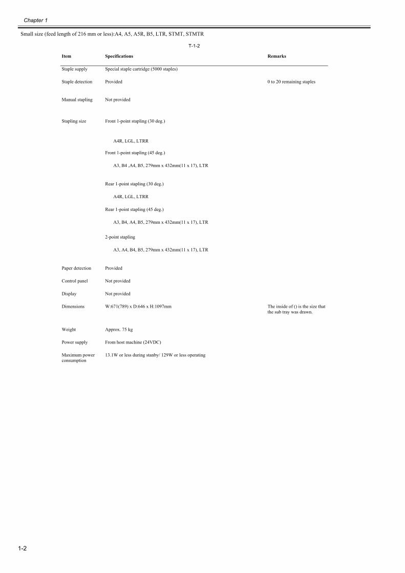
Small size (feed length of 216 mm or less):A4, A5, A5R, B5, LTR, STMT, STMTR
T-1-2
Item Specifications Remarks
Staple supply Special staple cartridge (5000 staples)
Staple detection Provided 0 to 20 remaining staples
Manual stapling Not provided
Stapling size Front 1-point stapling (30 deg.)
A4R, LGL, LTRR
Front 1-point stapling (45 deg.)
A3, B4 ,A4, B5, 279mm x 432mm(11 x 17), LTR
Rear 1-point stapling (30 deg.)
A4R, LGL, LTRR
Rear 1-point stapling (45 deg.)
A3, B4, A4, B5, 279mm x 432mm(11 x 17), LTR
2-point stapling
A3, A4, B4, B5, 279mm x 432mm(11 x 17), LTR
Paper detection Provided
Control panel Not provided
Display Not provided
Dimensions W:671(789) x D:646 x H:1097mm The inside of () is the size that the sub tray was drawn.
Weight Approx. 75 kg
Power supply From host machine (24VDC)
Maximum power consumption
13.1W or less during stanby/ 129W or less operating
Chapter 1
1-3
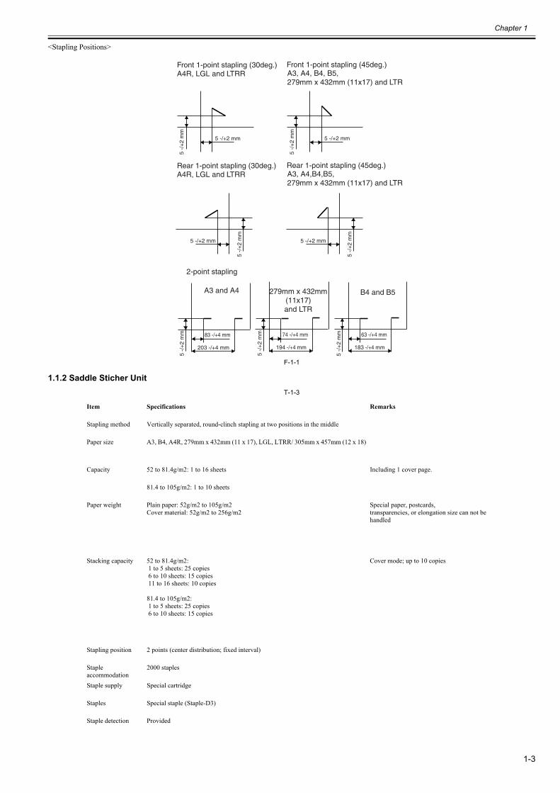
<Stapling Positions>
F-1-1
1.1.2 Saddle Sticher Unit0023-6349
T-1-3
Item Specifications Remarks
Stapling method Vertically separated, round-clinch stapling at two positions in the middle
Paper size A3, B4, A4R, 279mm x 432mm (11 x 17), LGL, LTRR/ 305mm x 457mm (12 x 18)
Capacity 52 to 81.4g/m2: 1 to 16 sheets Including 1 cover page.
81.4 to 105g/m2: 1 to 10 sheets
Paper weight Plain paper: 52g/m2 to 105g/m2Cover material: 52g/m2 to 256g/m2
Special paper, postcards,transparencies, or elongation size can not be handled
Stacking capacity 52 to 81.4g/m2: 1 to 5 sheets: 25 copies 6 to 10 sheets: 15 copies 11 to 16 sheets: 10 copies
81.4 to 105g/m2: 1 to 5 sheets: 25 copies 6 to 10 sheets: 15 copies
Cover mode; up to 10 copies
Stapling position 2 points (center distribution; fixed interval)
Staple accommodation
2000 staples
Staple supply Special cartridge
Staples Special staple (Staple-D3)
Staple detection Provided
B4 and B5
A4R, LGL and LTRR
A3 and A4 279mm x 432mm(11x17)and LTR
A3, A4, B4, B5,279mm x 432mm (11x17) and LTR
Front 1-point stapling (30deg.)
2-point stapling
Front 1-point stapling (45deg.)
A4R, LGL and LTRR A3, A4,B4,B5,279mm x 432mm (11x17) and LTR
Rear 1-point stapling (30deg.) Rear 1-point stapling (45deg.)
83 -/+4 mm
203 -/+4 mm
5 -/
+2
mm
5 -/+2 mm
5 -/
+2
mm
63 -/+4 mm
183 -/+4 mm
74 -/+4 mm
194 -/+4 mm
5 -/+2 mm
5 -/
+2
mm
5 -/+2 mm5
-/+
2 m
m5 -/+2 mm
5 -/
+2
mm
5 -/
+2
mm
5 -/
+2
mm
Chapter 1
1-4
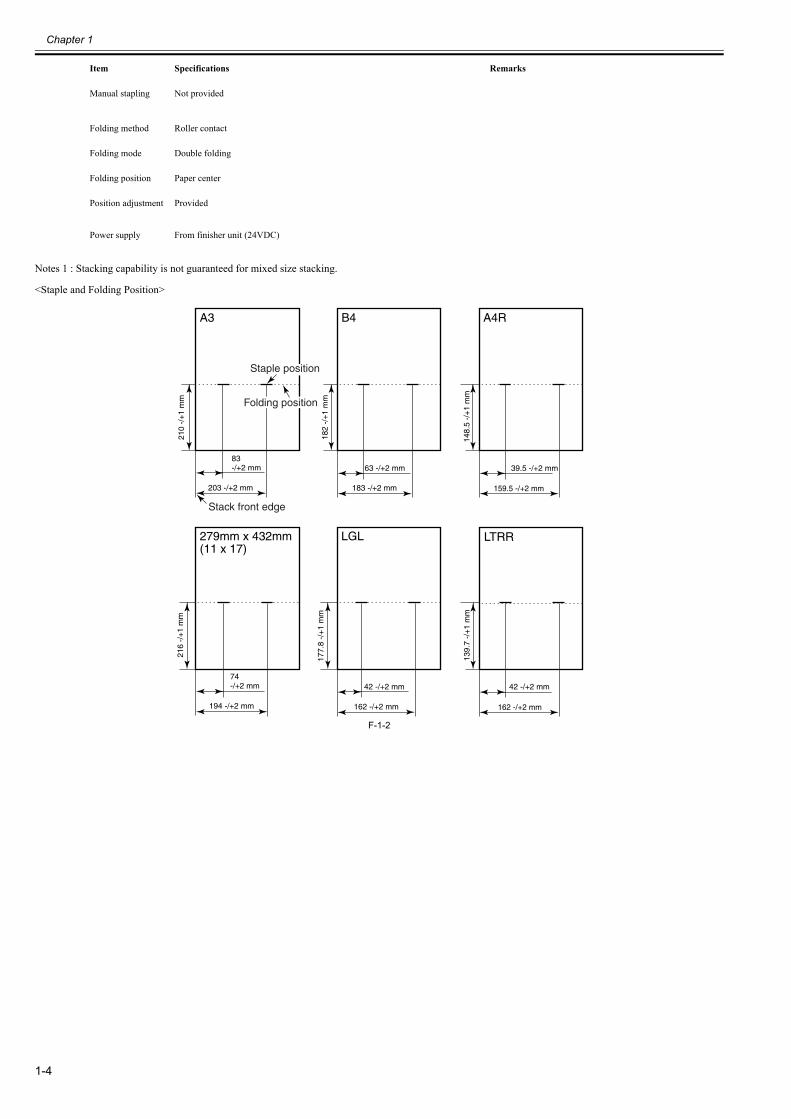
Notes 1 : Stacking capability is not guaranteed for mixed size stacking.
<Staple and Folding Position>
F-1-2
Manual stapling Not provided
Folding method Roller contact
Folding mode Double folding
Folding position Paper center
Position adjustment Provided
Power supply From finisher unit (24VDC)
Item Specifications Remarks
Stack front edge
162 -/+2 mm
139.
7 -/
+1
mm
42 -/+2 mm
203 -/+2 mm
210
-/+
1 m
m
83-/+2 mm
A3
183 -/+2 mm
182
-/+
1 m
m
63 -/+2 mm
B4
194 -/+2 mm
216
-/+
1 m
m
74-/+2 mm
162 -/+2 mm
177.
8 -/
+1
mm
42 -/+2 mm
LGL
159.5 -/+2 mm
148.
5 -/
+1
mm
39.5 -/+2 mm
A4R
279mm x 432mm(11 x 17)
LTRR
Staple position
Folding position
Chapter 1
1-5
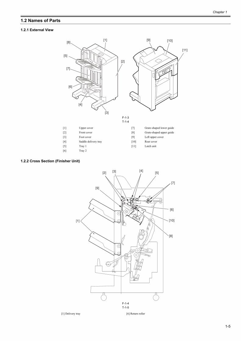
1.2 Names of Parts
1.2.1 External View0023-6351
F-1-3T-1-4
1.2.2 Cross Section (Finisher Unit)0023-6355
F-1-4T-1-5
[1] Upper cover [7] Grate-shaped lower guide[2] Front cover [8] Grate-shaped upper guide[3] Foot cover [9] Left upper cover[4] Saddle delivery tray [10] Rear cover[5] Tray 1 [11] Latch unit[6] Tray 2
[1] Delivery tray [6] Return roller
[5]
[2]
[1]
[4]
[3]
[10]
[11]
[8]
[6]
[7]
[9]
[2] [3]
[7]
[9]
[1]
[8]
[10]
[5]
[6]
[4]
Chapter 1
1-6
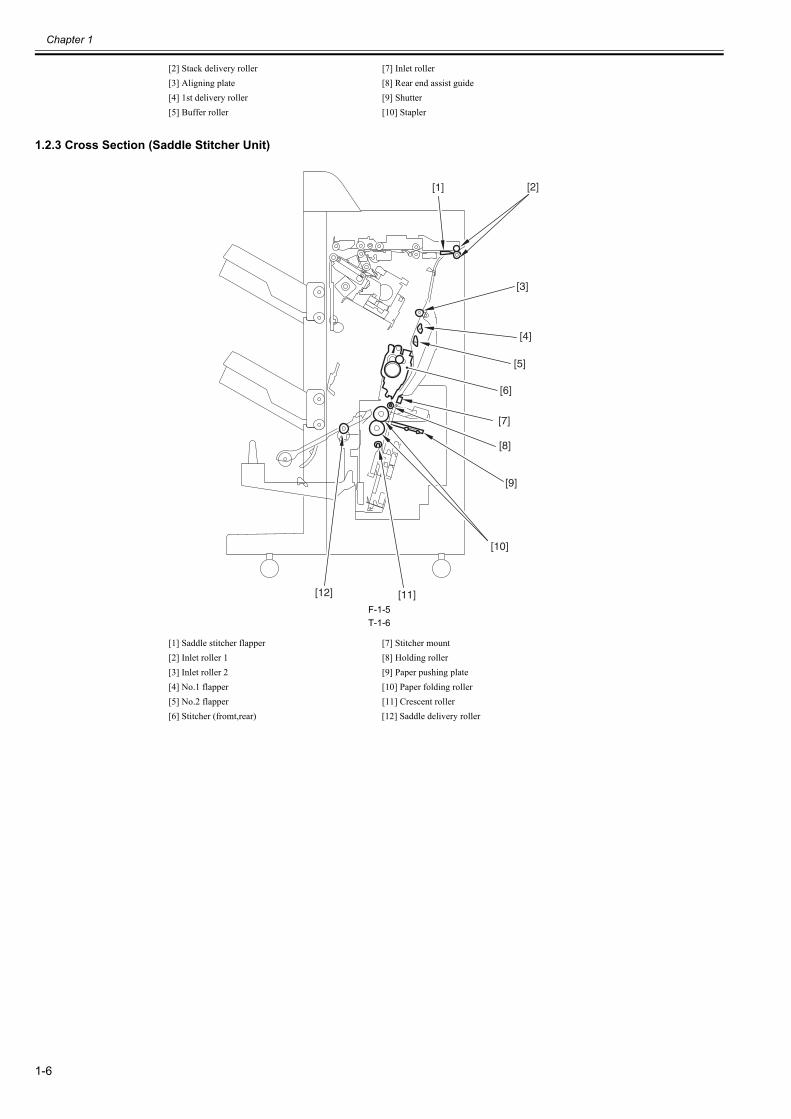
1.2.3 Cross Section (Saddle Stitcher Unit)0023-6360
F-1-5T-1-6
[2] Stack delivery roller [7] Inlet roller[3] Aligning plate [8] Rear end assist guide[4] 1st delivery roller [9] Shutter[5] Buffer roller [10] Stapler
[1] Saddle stitcher flapper [7] Stitcher mount[2] Inlet roller 1 [8] Holding roller[3] Inlet roller 2 [9] Paper pushing plate[4] No.1 flapper [10] Paper folding roller[5] No.2 flapper [11] Crescent roller[6] Stitcher (fromt,rear) [12] Saddle delivery roller
[1] [2]
[3]
[4]
[5]
[6]
[7]
[8]
[9]
[10]
[11][12]

Chapter 2 Functions

Contents
Contents
2.1 Basic Operation..............................................................................................................................................................2-12.1.1 Basic Operation (Finisher Unit)................................................................................................................................................... 2-12.1.2 Overview of the Electrical Circuitry (Finisher Unit) ................................................................................................................... 2-12.1.3 Basic Operation (Saddle Stitcher Unit)........................................................................................................................................ 2-22.1.4 Overview of the Electrical Circuitry (Saddle Stitcher Unit)........................................................................................................ 2-2
2.2 Feed Drive System .........................................................................................................................................................2-32.2.1 Overview...................................................................................................................................................................................... 2-32.2.2 Constraction of the Control System (Finisher Unit) .................................................................................................................... 2-32.2.3 Paper Delivery Path (Finisher Unit) ............................................................................................................................................ 2-52.2.4 Constraction of the Control System (Saddle Stitcher Unit)......................................................................................................... 2-82.2.5 Paper Delivery Path (Saddle Stitcher Unit) ................................................................................................................................. 2-92.2.6 Controlling the Change of the Gear ........................................................................................................................................... 2-102.2.7 Basic Operation (Saddle Stitcher Unit)...................................................................................................................................... 2-112.2.8 Controlling the Inlet Flappers .................................................................................................................................................... 2-142.2.9 Controlling the Movement of Sheets ......................................................................................................................................... 2-172.2.10 Controlling the Aligning the Sheets......................................................................................................................................... 2-182.2.11 Controlling the Phase of the Crescent Roller........................................................................................................................... 2-202.2.12 Overview of Folding Operation ............................................................................................................................................... 2-222.2.13 Controlling the Movement of Stacks ....................................................................................................................................... 2-222.2.14 Folding a Stack ........................................................................................................................................................................ 2-232.2.15 Double Folding a Stack............................................................................................................................................................ 2-25
2.3 Intermediate Process Tray Assembly...........................................................................................................................2-262.3.1 Stack Job Offset ......................................................................................................................................................................... 2-262.3.2 Processing Tray Paper Stacking Operation................................................................................................................................ 2-272.3.3 Offset Operation......................................................................................................................................................................... 2-282.3.4 Rear End Assist Operation......................................................................................................................................................... 2-282.3.5 Stack Delivery Operation........................................................................................................................................................... 2-292.3.6 Swing Height Detection Control................................................................................................................................................ 2-29
2.4 Staple Operation...........................................................................................................................................................2-302.4.1 Overview.................................................................................................................................................................................... 2-302.4.2 Stapler Unit ................................................................................................................................................................................ 2-312.4.3 Shifting the Stapler Unit ............................................................................................................................................................ 2-312.4.4 Stapling Operation ..................................................................................................................................................................... 2-332.4.5 Stitcher Unit ............................................................................................................................................................................... 2-362.4.6 Stitching Operation .................................................................................................................................................................... 2-37
2.5 Stack Tray Operation ...................................................................................................................................................2-372.5.1 Tray Operation ........................................................................................................................................................................... 2-372.5.2 Shutter Operation ....................................................................................................................................................................... 2-39
2.6 Detecting Jams .............................................................................................................................................................2-392.6.1 Detecting Jams (Finisher Unit) .................................................................................................................................................. 2-392.6.2 Detecting Jams (Saddle Stitcher Unit) ....................................................................................................................................... 2-41
2.7 Power Supply ...............................................................................................................................................................2-432.7.1 Power Supply Route (Finisher Unit).......................................................................................................................................... 2-432.7.2 Protection Function (Finisher Unit) ........................................................................................................................................... 2-432.7.3 Power Supply Route (Saddle Stitcher Unit) .............................................................................................................................. 2-432.7.4 Protection Function (Saddle Stitcher Unit)................................................................................................................................ 2-44

Chapter 2
2-1
2.1 Basic Operation
2.1.1 Basic Operation (Finisher Unit)0023-6369
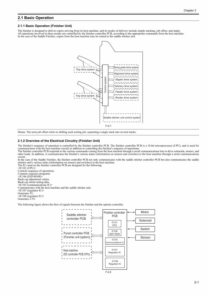
The finisher is designed to deliver copies arriving from its host machine, and its modes of delivery include simple stacking, job offset, and staple.All operations involved in these modes are controlled by the finisher controller PCB, according to the appropriate commands from the host machine.In the case of the Saddle Finisher, copies from the host machine may be routed to the saddle stitcher unit.
F-2-1
Memo: The term job offset refers to shifting each sorting job, separating a single stack into several stacks.
2.1.2 Overview of the Electrical Circuitry (Finisher Unit)0023-6376
The finisher's sequence of operation is controlled by the finisher controller PCB. The finisher controller PCB is a 16-bit microprocessor (CPU), and is used forcommunication with the host machine (serial) in addition to controlling the finisher's sequence of operations.The finisher controller PCB responds to the various commands coming from the host machine through a serial communications line to drive solenoids, motors, andother loads. In addition, it communicates the finisher's various states (information on sensors and switches) to the host machine through a serial communicationscircuit.In the case of the Saddle Finisher, the finisher controller PCB not only communicates with the saddle stitcher controller PCB but also communicates the saddlestitcher unit's various states (information on sensors and switches) to the host machine.The ICs used on the finisher controller PCB are designed for the following:<IC101 (CPU)>Controls sequence of operations.Contains sequence programs.<IC106 (EEP-ROM)>Backs up adjustment values.Backs up initial setting data.<IC102 (communications IC)>Communicates with the host machine and the saddle stitcher unit.<IC107 (regulator IC)>Generates 5V.<IC108 (regulator IC)>Generates 3.3V.
The following figure shows the flow of signals between the finisher and the options controller.
F-2-2
Swing guide drive system
Alignment drive system
Stapler drive system
Delivery drive system
Feeder drive system
Shutter drive system
Tray drive system
Saddle stitcher unit control system
Con
trol
sys
tem
Tray drive system
IC101CPU
IC106EEP-ROM
Saddle stitcher controller PCB
Punch controller PCB(Puncher unit (option))
Host machine(DC controller PCB CPU)
Finisher controller PCB
IC108Regulator IC
IC102Communications IC
Motor
Solenoid
Switch
Sensor
IC107Regulator IC
Chapter 2
2-2
2.1.3 Basic Operation (Saddle Stitcher Unit)0023-6384
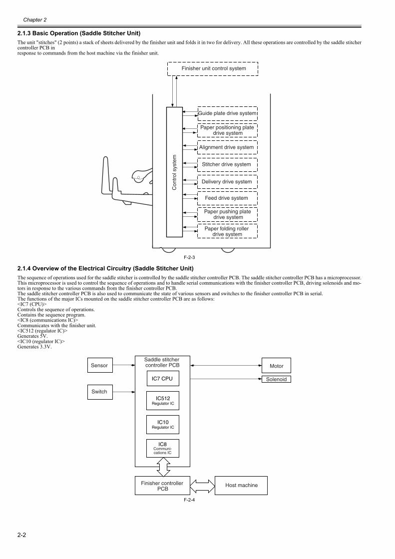
The unit "stitches" (2 points) a stack of sheets delivered by the finisher unit and folds it in two for delivery. All these operations are controlled by the saddle stitchercontroller PCB inresponse to commands from the host machine via the finisher unit.
F-2-3
2.1.4 Overview of the Electrical Circuitry (Saddle Stitcher Unit)0023-6385
The sequence of operations used for the saddle stitcher is controlled by the saddle stitcher controller PCB. The saddle stitcher controller PCB has a microprocessor.This microprocessor is used to control the sequence of operations and to handle serial communications with the finisher controller PCB, driving solenoids and mo-tors in response to the various commands from the finisher controller PCB.The saddle stitcher controller PCB is also used to communicate the state of various sensors and switches to the finisher controller PCB in serial.The functions of the major ICs mounted on the saddle stitcher controller PCB are as follows:<IC7 (CPU)>Controls the sequence of operations.Contains the sequence program.<IC8 (communications IC)>Communicates with the finisher unit.<IC512 (regulator IC)>Generates 5V.<IC10 (regulator IC)>Generates 3.3V.
F-2-4
Finisher unit control system
Con
trol
sys
tem
Guide plate drive system
Paper positioning plate drive system
Alignment drive system
Stitcher drive system
Delivery drive system
Feed drive system
Paper pushing plate drive system
Paper folding roller drive system
Sensor
Switch
IC7 CPU
IC10Regulator IC
IC8Communi-cations IC
Saddle stitcher controller PCB Motor
Solenoid
Host machineFinisher controller PCB
IC512Regulator IC
Chapter 2
2-3
2.2 Feed Drive System
2.2.1 Overview0023-6386
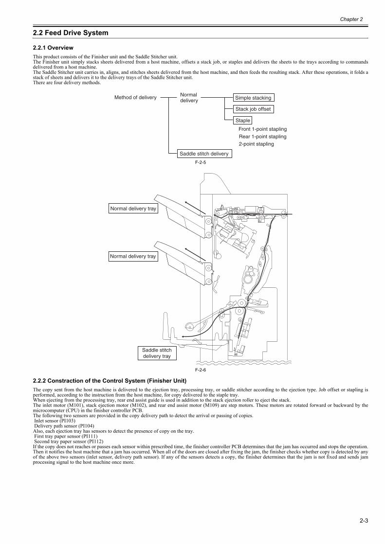
This product consists of the Finisher unit and the Saddle Stitcher unit.The Finisher unit simply stacks sheets delivered from a host machine, offsets a stack job, or staples and delivers the sheets to the trays according to commandsdelivered from a host machine.The Saddle Stitcher unit carries in, aligns, and stitches sheets delivered from the host machine, and then feeds the resulting stack. After these operations, it folds astack of sheets and delivers it to the delivery trays of the Saddle Stitcher unit.There are four delivery methods.
F-2-5
F-2-6
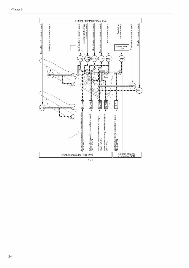
2.2.2 Constraction of the Control System (Finisher Unit)0023-6390
The copy sent from the host machine is delivered to the ejection tray, processing tray, or saddle stitcher according to the ejection type. Job offset or stapling isperformed, according to the instruction from the host machine, for copy delivered to the staple tray.When ejecting from the processing tray, rear end assist guide is used in addition to the stack ejection roller to eject the stack.The inlet motor (M101), stack ejection motor (M102), and rear end assist motor (M109) are step motors. These motors are rotated forward or backward by themicrocomputer (CPU) in the finisher controller PCB. The following two sensors are provided in the copy delivery path to detect the arrival or passing of copies. Inlet sensor (PI103) Delivery path sensor (PI104)Also, each ejection tray has sensors to detect the presence of copy on the tray. First tray paper sensor (PI111) Second tray paper sensor (PI112)If the copy does not reaches or passes each sensor within prescribed time, the finisher controller PCB determines that the jam has occurred and stops the operation.Then it notifies the host machine that a jam has occurred. When all of the doors are closed after fixing the jam, the finisher checks whether copy is detected by anyof the above two sensors (inlet sensor, delivery path sensor). If any of the sensors detects a copy, the finisher determines that the jam is not fixed and sends jamprocessing signal to the host machine once more.
Method of delivery Normal delivery Simple stacking
Stack job offset
Staple
Front 1-point stapling
2-point stapling
Saddle stitch delivery
Rear 1-point stapling
Normal delivery tray
Normal delivery tray
Saddle stitchdelivery tray
Chapter 2
2-4
F-2-7
M109M110
Sec
ond
tray
shi
ft m
otor
driv
e si
gnal
Firs
t tra
y sh
ift m
otor
driv
e si
gnal
1st e
ject
rol
ler
sepa
ratio
n so
leno
id d
rive
sign
alD
ELI
V-R
OL-
SL
Sad
dle
inle
t sw
itchi
ng s
olen
oid
driv
e si
gnal
SD
L-IN
LET-
SL
Inle
t rol
ler
sepa
ratio
n so
leno
id d
rive
sign
alIN
LET-
RO
L-S
L
Buf
fer
rolle
r se
para
tion
sole
noid
driv
e si
gnal
BU
FF
-RO
L-S
L
Buf
fer
rear
end
hol
ding
sol
enoi
d dr
ive
sign
alB
UF
F-P
-SL
Saddle driverPCB
Finisher controller PCB (1/2)
Finisher controller PCB (2/2)
M102 M101
M105
M9
M107
M108 SL1
04
SL1
01
SL1
02
SL1
03
SL5
M103M104
M41
Sta
ck e
ject
ion
mot
or d
rive
sign
al
Rea
r en
d as
sist
mot
or d
rive
sign
al
Inle
t mot
or d
rive
sign
al
Sad
dle
inle
tm
otor
driv
e si
gnal
Sta
pler
driv
e m
otor
driv
e si
gnal
Sta
pler
mot
or d
rive
sign
al
Alig
ning
pla
te fr
ont/r
ear
mot
or d
rive
sign
al
Gea
r ch
ange
mot
or d
rive
sign
al
Saddle stitchercontroller PCB
Chapter 2
2-5
F-2-8
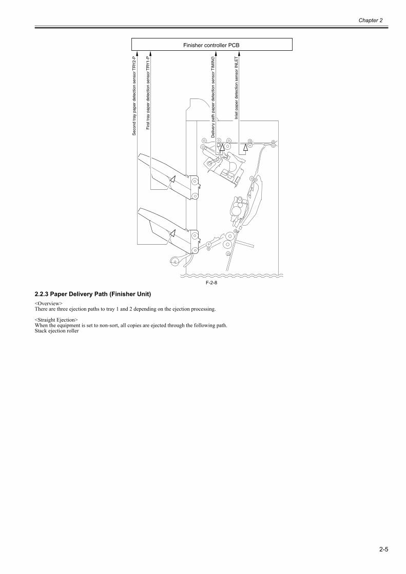
2.2.3 Paper Delivery Path (Finisher Unit)0023-6392
<Overview>There are three ejection paths to tray 1 and 2 depending on the ejection processing.
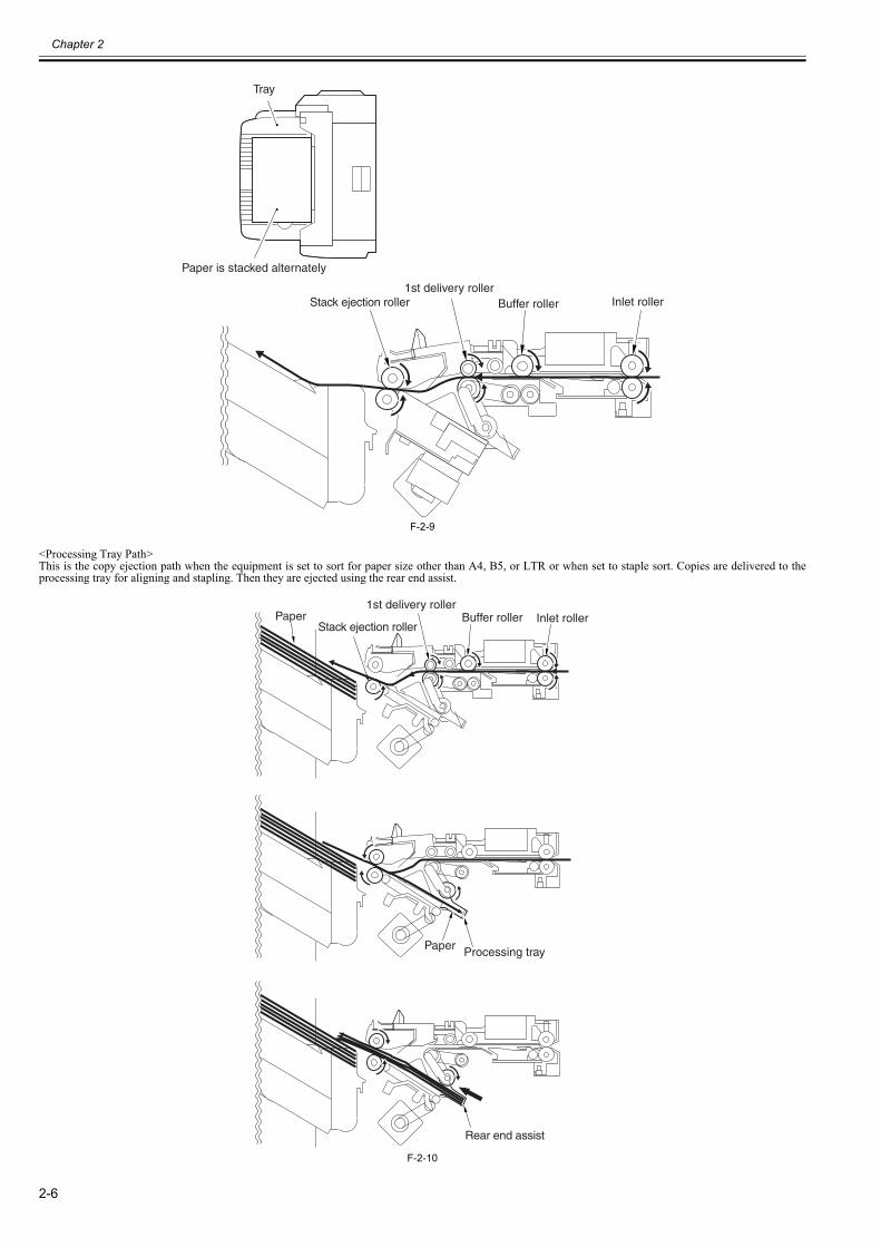
<Straight Ejection>When the equipment is set to non-sort, all copies are ejected through the following path.Stack ejection roller
Del
iver
y pa
th p
aper
det
ectio
n se
nsor
TIM
ING
Inle
t pap
er d
etec
tion
sens
or IN
LET
Sec
ond
tray
pap
er d
etec
tion
sens
or T
RY
2-P
Firs
t tra
y pa
per
dete
ctio
n se
nsor
TR
Y1-
P
Finisher controller PCB
Chapter 2
2-6
F-2-9
<Processing Tray Path>This is the copy ejection path when the equipment is set to sort for paper size other than A4, B5, or LTR or when set to staple sort. Copies are delivered to theprocessing tray for aligning and stapling. Then they are ejected using the rear end assist.
F-2-10
Stack ejection roller1st delivery roller
Buffer roller Inlet roller
Tray
Paper is stacked alternately
Stack ejection roller
Rear end assist
1st delivery rollerBuffer roller Inlet rollerPaper
Processing trayPaper
Chapter 2
2-7
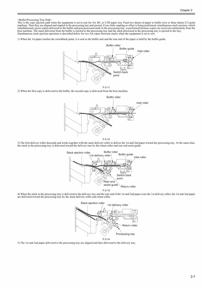
<Buffer/Processing Tray Path>This is the copy ejection path when the equipment is set to sort for A4, B5, or LTR paper size. Feed two sheets of paper to buffer (two or three sheets if 2-pointstapling). Then they are aligned and stapled in the processing tray and ejected. Even while stapling or offset is being performed, simultaneous stack ejection, whichsimultaneously ejects copies delivered to the buffer and post processed stack in the processing tray, is performed because copies are received continuously from thehost machine. The stack delivered from the buffer is ejected to the processing tray and the stack processed in the processing tray is ejected to the tray.Simultaneous stack ejection operation is described below for two A4 copies between stacks when the equipment is set to sort.
1) When the 1st paper reaches the switchback point, it is sent to the buffer unit and the rear end of the paper is held by the buffer guide.
F-2-112) When the first copy is delivered to the buffer, the second copy is delivered from the host machine.
F-2-123) The first delivery roller descends and works together with the stack delivery roller to deliver the 1st and 2nd paper toward the processing tray. At the same time,the stack in the processing tray is delivered toward the delivery tray by the return roller and rear end assist guide.
F-2-134) When the stack in the processing tray is delivered to the delivery tray and the rear end of the 1st and 2nd paper exits the 1st delivery roller, the 1st and 2nd paperare delivered toward the processing tray by the stack delivery roller and return roller.
F-2-145) The 1st and 2nd paper delivered to the processing tray are aligned and then delivered to the delivery tray.
20mm
Buffer roller
Inlet rollerBuffer guide
Switch back point
Buffer roller
Inlet roller
20mm
Stack ejection roller1st delivery roller
Buffer roller
Inlet rollerBuffer guide
Rear end assist guide
Return roller
Switch back point
Stack ejection roller1st delivery roller
Return roller
Processing tray
Chapter 2
2-8
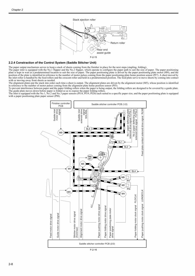
F-2-15
2.2.4 Constraction of the Control System (Saddle Stitcher Unit)0023-6395
The paper output mechanism serves to keep a stack of sheets coming from the finisher in place for the next steps (stapling, folding).The paper inlet is equipped with the No.1 flapper and the No.2 flapper, which operate to configure the paper path to suit the size of paper. The paper positioningplate is kept in wait at a predetermined location to suit the size of paper. The paper positioning plate is driven by the paper positioning plate motor (M4), and theposition of the plate is identified in reference to the number of motor pulses coming from the paper positioning plate home position sensor (PI7). A sheet moved bythe inlet roller is handled by the feed rollers and the crescent roller and held in a predetermined position. The feed plate serve to move sheets by coming into contactwith or moving away from sheets as needed.The alignment plates put the stack into order each time a sheet is output. The alignment plates are driven by the alignment motor (M5), whose position is identifiedin reference to the number of motor pulses coming from the alignment plate home position sensor (PI5).To prevent interference between paper and the paper folding rollers when the paper is being output, the folding rollers are designed to be covered by a guide plate.The guide plate moves down before paper is folded so as to expose the paper folding rollers.The inlet is equipped with the No.1, No.2 and No.3 paper sensors (PI18, PI19, PI20) each suited to a specific paper size, and the paper positioning plate is equippedwith a paper positioning plate paper sensor (PI8).
F-2-16
Stack ejection roller
Rear end assist guide
Return roller
SL1
SL4
SL2
M8
M6/M7
M1
M5
M3
PI1
M2
M4
PI4
Fee
d m
otor
driv
e si
gnal
Gui
de m
otor
driv
e si
gnal
Stit
cher
mot
or d
rive
sign
al
(fro
nt/r
ear)
Pap
er p
ushi
ng m
otor
driv
e si
gnal
Alig
nmen
t mot
or d
rive
sign
al
Pap
er p
ushi
ng m
otor
clo
ck s
igna
l L
UN
GE
CLK
No.
1 pa
per
defle
ctin
g pl
ate
sole
noid
driv
e si
gnal
FLP
SL1
No.
2 pa
per
defle
ctin
g pl
ate
sole
noid
driv
e si
gnal
F
LPS
L2
Fee
d pl
ate
cont
act s
olen
oid
driv
e si
gnal
RLN
IPS
L
Pap
er fo
ldin
g m
otor
clo
ck s
igna
l F
LDC
LK
Pap
er fo
ldin
g m
otor
driv
e si
gnal
Pap
er p
ositi
onin
g pl
ate
mot
or
driv
e si
gnal
Saddle stitcher controller PCB (2/2)
Sad
dle
inle
t s
olen
oid
driv
e s
igna
lS
DLI
NS
L
M9
SL5
Sad
dle
inle
t m
otor
driv
e s
igna
l
Saddle stitcher controller PCB (1/2)Finisher controllerPCB
Chapter 2
2-9
F-2-17
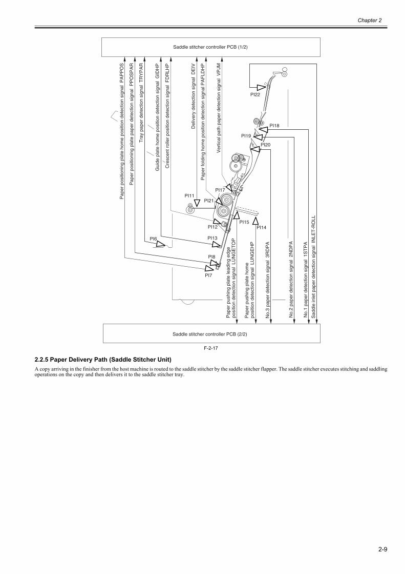
2.2.5 Paper Delivery Path (Saddle Stitcher Unit)0023-6396
A copy arriving in the finisher from the host machine is routed to the saddle stitcher by the saddle stitcher flapper. The saddle stitcher executes stitching and saddlingoperations on the copy and then delivers it to the saddle stitcher tray.
Saddle stitcher controller PCB (2/2)
Saddle stitcher controller PCB (1/2)
PI19
PI18
PI20
PI15
PI7
PI8
PI13
PI12
PI11PI17
PI6
PI14P
aper
pus
hing
pla
te le
adin
g ed
ge
posi
tion
dete
ctio
n si
gnal
LU
NG
ET
OP
Pap
er p
ushi
ng p
late
hom
e po
sitio
n de
tect
ion
sign
al L
UN
GE
HP
No.
3 pa
per
dete
ctio
n si
gnal
3R
DP
A
No.
2 pa
per
dete
ctio
n si
gnal
2N
DP
A
No.
1 pa
per
dete
ctio
n si
gnal
1S
TP
A
PI21
Pap
er p
ositi
onin
g pl
ate
hom
e po
sitio
n de
tect
ion
sign
al P
AP
PO
S
Pap
er p
ositi
onin
g pl
ate
pape
r de
tect
ion
sign
al P
PO
SP
AR
Tra
y pa
per
dete
ctio
n si
gnal
TR
YP
AR
Gui
de p
late
hom
e po
sitio
n de
tect
ion
sign
al G
IDH
P
Cre
scen
t rol
ler
posi
tion
dete
ctio
n si
gnal
FD
RLH
P
Del
iver
y de
tect
ion
sign
al D
EIV
Pap
er fo
ldin
g ho
me
posi
tion
dete
ctio
n si
gnal
PA
FLD
HP
Ver
tical
pat
h pa
per
dete
ctio
n si
gnal
VP
JM
PI22
Sad
dle
inle
t pap
er d
etec
tion
sign
al I
NLE
T-R
OLL
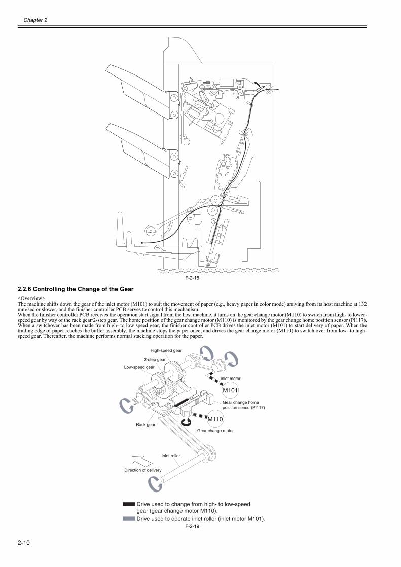
Chapter 2
2-10
F-2-18
2.2.6 Controlling the Change of the Gear0023-6397
<Overview>The machine shifts down the gear of the inlet motor (M101) to suit the movement of paper (e.g., heavy paper in color mode) arriving from its host machine at 132mm/sec or slower, and the finisher controller PCB serves to control this mechanism.When the finisher controller PCB receives the operation start signal from the host machine, it turns on the gear change motor (M110) to switch from high- to lower-speed gear by way of the rack gear/2-step gear. The home position of the gear change motor (M110) is monitored by the gear change home position sensor (PI117).When a switchover has been made from high- to low speed gear, the finisher controller PCB drives the inlet motor (M101) to start delivery of paper. When thetrailing edge of paper reaches the buffer assembly, the machine stops the paper once, and drives the gear change motor (M110) to switch over from low- to high-speed gear. Thereafter, the machine performs normal stacking operation for the paper.
F-2-19
M101
M110
Drive used to change from high- to low-speed gear (gear change motor M110).Drive used to operate inlet roller (inlet motor M101).
Inlet roller
Rack gear
Gear change motor
Inlet motor
Gear change homeposition sensor(PI117)
High-speed gear
Low-speed gear
2-step gear
Direction of delivery
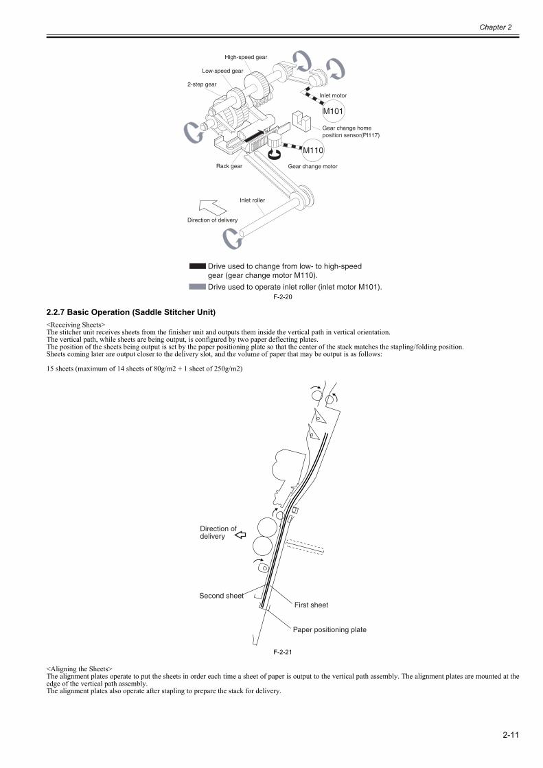
Chapter 2
2-11
F-2-20
2.2.7 Basic Operation (Saddle Stitcher Unit)0023-6398
<Receiving Sheets>The stitcher unit receives sheets from the finisher unit and outputs them inside the vertical path in vertical orientation.The vertical path, while sheets are being output, is configured by two paper deflecting plates.The position of the sheets being output is set by the paper positioning plate so that the center of the stack matches the stapling/folding position.Sheets coming later are output closer to the delivery slot, and the volume of paper that may be output is as follows:
15 sheets (maximum of 14 sheets of 80g/m2 + 1 sheet of 250g/m2)
F-2-21
<Aligning the Sheets>The alignment plates operate to put the sheets in order each time a sheet of paper is output to the vertical path assembly. The alignment plates are mounted at theedge of the vertical path assembly.The alignment plates also operate after stapling to prepare the stack for delivery.
M101
M110
Drive used to change from low- to high-speed gear (gear change motor M110).
Drive used to operate inlet roller (inlet motor M101).
Inlet roller
Rack gear Gear change motor
Inlet motor
Gear change homeposition sensor(PI117)
High-speed gear
Low-speed gear
2-step gear
Direction of delivery
Paper positioning plate
First sheetSecond sheet
Direction of delivery
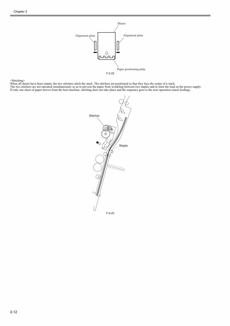
Chapter 2
2-12
F-2-22
<Stitching>When all sheets have been output, the two stitchers stitch the stack. The stitchers are positioned so that they face the center of a stack.The two stitchers are not operated simultaneously so as to prevent the paper from wrinkling between two staples and to limit the load on the power supply.If only one sheet of paper arrives from the host machine, stitching does not take place and the sequence goes to the next operation (stack feeding).
F-2-23
Sheets
Paper positioning plate
Alignment plateAlignment plate
Stitcher
Staple
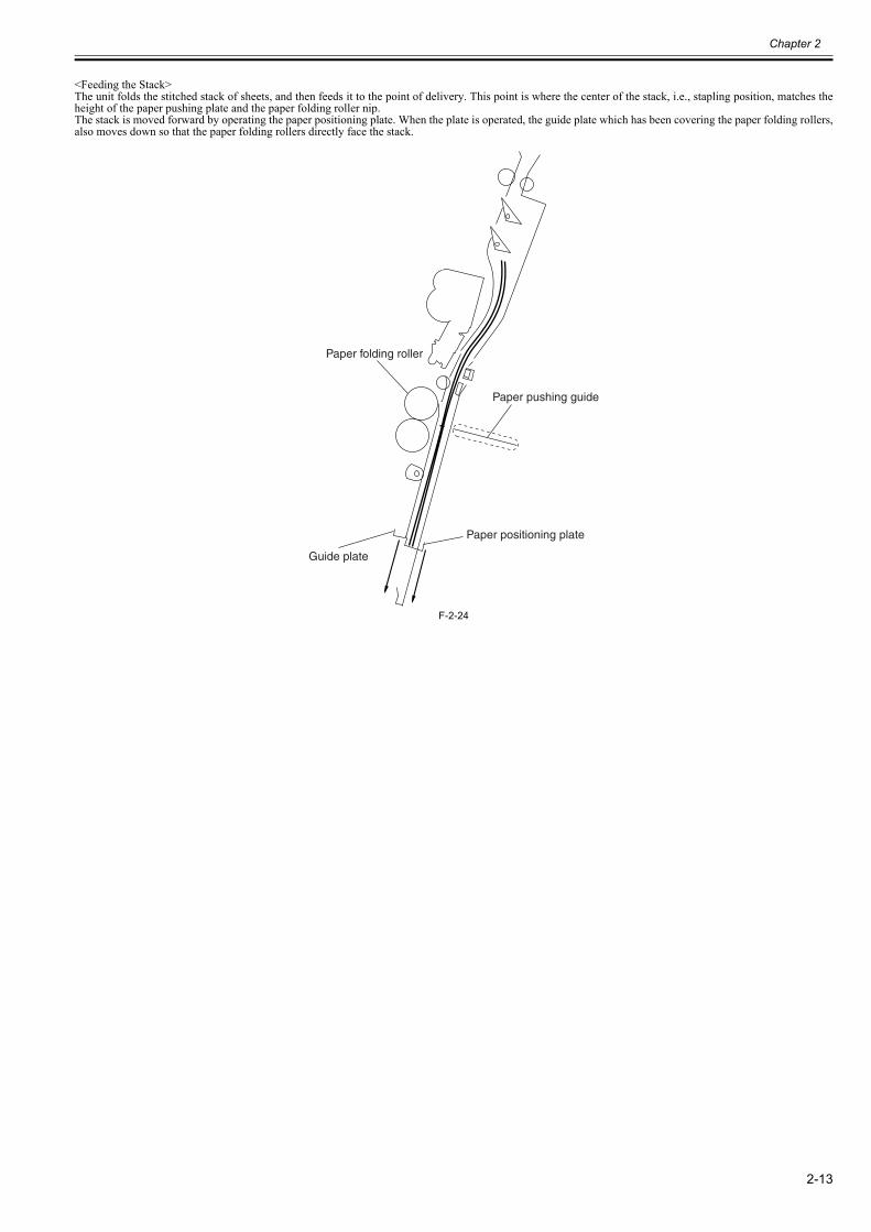
Chapter 2
2-13
<Feeding the Stack>The unit folds the stitched stack of sheets, and then feeds it to the point of delivery. This point is where the center of the stack, i.e., stapling position, matches theheight of the paper pushing plate and the paper folding roller nip.The stack is moved forward by operating the paper positioning plate. When the plate is operated, the guide plate which has been covering the paper folding rollers,also moves down so that the paper folding rollers directly face the stack.
F-2-24
Paper folding roller
Guide plate
Paper positioning plate
Paper pushing guide
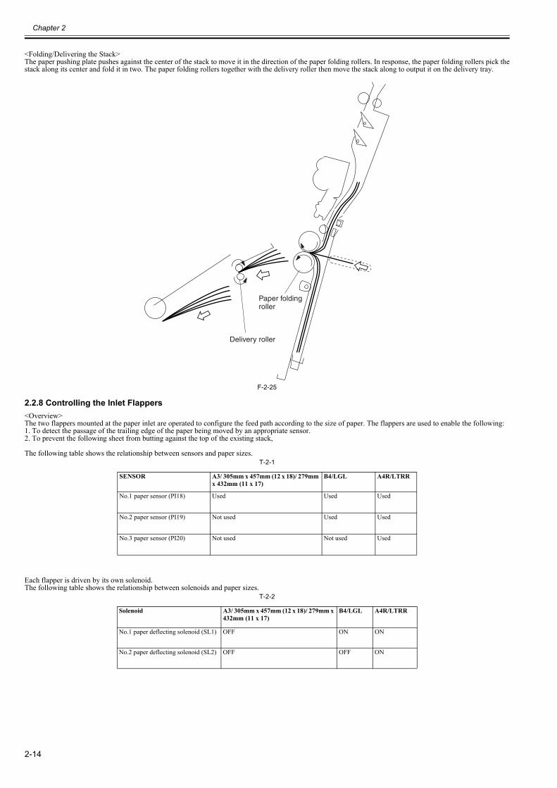
Chapter 2
2-14
<Folding/Delivering the Stack>The paper pushing plate pushes against the center of the stack to move it in the direction of the paper folding rollers. In response, the paper folding rollers pick thestack along its center and fold it in two. The paper folding rollers together with the delivery roller then move the stack along to output it on the delivery tray.
F-2-25
2.2.8 Controlling the Inlet Flappers0023-6399
<Overview>The two flappers mounted at the paper inlet are operated to configure the feed path according to the size of paper. The flappers are used to enable the following:1. To detect the passage of the trailing edge of the paper being moved by an appropriate sensor.2. To prevent the following sheet from butting against the top of the existing stack,
The following table shows the relationship between sensors and paper sizes.T-2-1
Each flapper is driven by its own solenoid.The following table shows the relationship between solenoids and paper sizes.
T-2-2
SENSOR A3/ 305mm x 457mm (12 x 18)/ 279mm x 432mm (11 x 17)
B4/LGL A4R/LTRR
No.1 paper sensor (PI18) Used Used Used
No.2 paper sensor (PI19) Not used Used Used
No.3 paper sensor (PI20) Not used Not used Used
Solenoid A3/ 305mm x 457mm (12 x 18)/ 279mm x 432mm (11 x 17)
B4/LGL A4R/LTRR
No.1 paper deflecting solenoid (SL1) OFF ON ON
No.2 paper deflecting solenoid (SL2) OFF OFF ON
Delivery roller
Paper folding roller
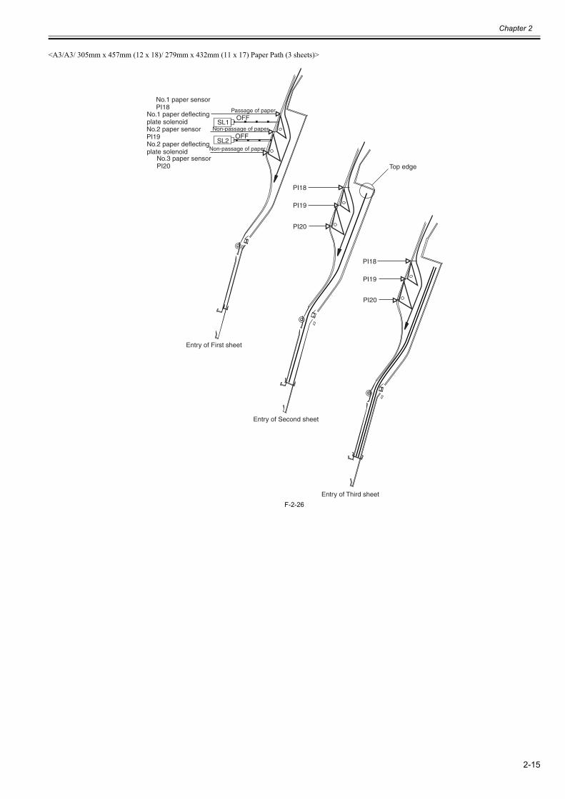
Chapter 2
2-15
<A3/A3/ 305mm x 457mm (12 x 18)/ 279mm x 432mm (11 x 17) Paper Path (3 sheets)>
F-2-26
No.1 paper sensorPI18
No.2 paper sensorPI19
No.3 paper sensorPI20
No.1 paper deflecting plate solenoid
No.2 paper deflecting plate solenoid
Passage of paper
Non-passage of paper
Non-passage of paper
Entry of First sheet
Entry of Second sheet
Entry of Third sheet
SL1
SL2
OFF
OFF
PI18
PI19
PI20
PI18
PI19
PI20
Top edge
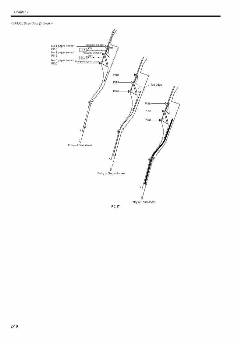
Chapter 2
2-16
<B4/LGL Paper Path (3 sheets)>
F-2-27
No.1 paper sensorPI18No.2 paper sensorPI19
No.3 paper sensorPI20
Passage of paper
Passage of paper
Non-passage of paper
Entry of First sheet
Entry of Second sheet
Entry of Third sheet
Top edge
SL1
SL2
ON
OFF
PI18
PI19
PI20
PI18
PI19
PI20
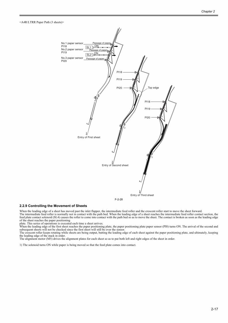
Chapter 2
2-17
<A4R/LTRR Paper Path (3 sheets)>
F-2-28
2.2.9 Controlling the Movement of Sheets0023-6400
When the leading edge of a sheet has moved past the inlet flapper, the intermediate feed roller and the crescent roller start to move the sheet forward.The intermediate feed roller is normally not in contact with the path bed. When the leading edge of a sheet reaches the intermediate feed roller contact section, thefeed plate contact solenoid (SL4) causes the roller to come into contact with the path bed so as to move the sheet. The contact is broken as soon as the leading edgeof the sheet reaches the paper positioningplate. This series of operations is executed each time a sheet arrives.When the leading edge of the first sheet reaches the paper positioning plate, the paper positioning plate paper sensor (PI8) turns ON. The arrival of the second andsubsequent sheets will not be checked since the first sheet will still be over the sensor.The crescent roller keeps rotating while sheets are being output, butting the leading edge of each sheet against the paper positioning plate, and ultimately, keepingthe leading edge of the stack in order.The alignment motor (M5) drives the alignment plates for each sheet so as to put both left and right edges of the sheet in order.
1) The solenoid turns ON while paper is being moved so that the feed plate comes into contact.
No.1 paper sensorPI18No.2 paper sensorPI19
No.3 paper sensorPI20
Passage of paper
Passage of paper
Passage of paper
Entry of First sheet
Entry of Second sheet
Entry of Third sheet
Top edge
SL1
SL2
ON
ON
PI18
PI19
PI20
PI18
PI19
PI20
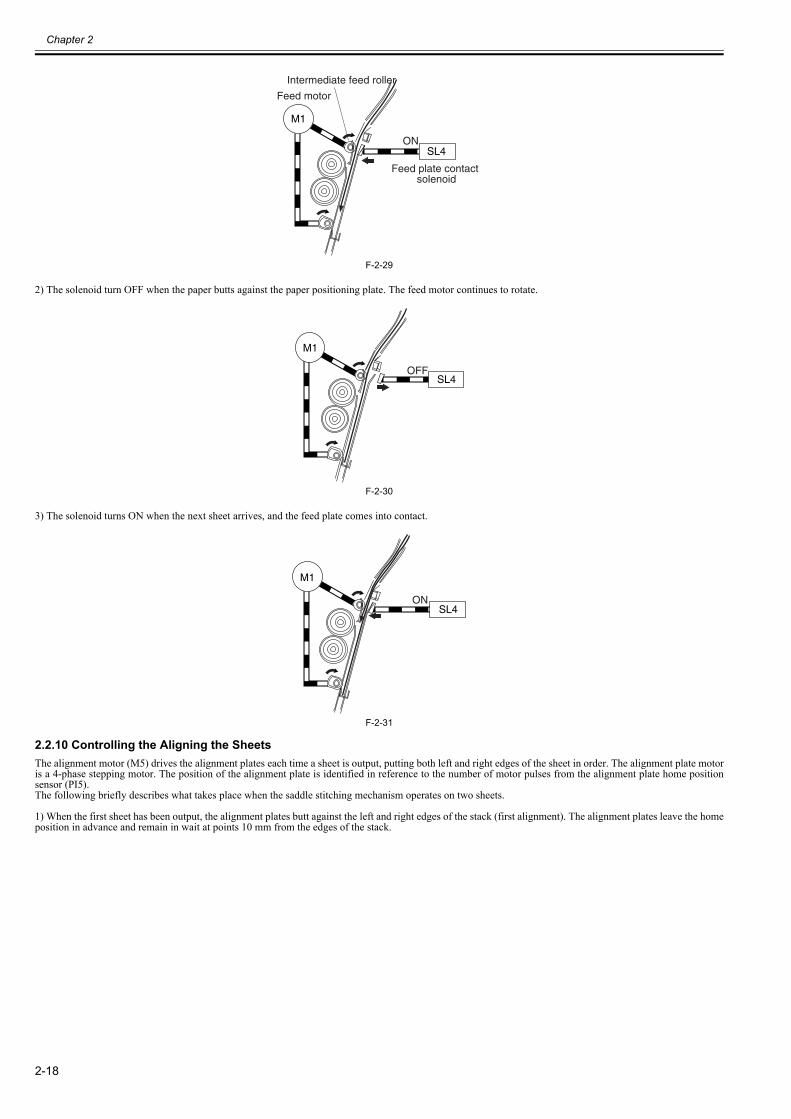
Chapter 2
2-18
F-2-29
2) The solenoid turn OFF when the paper butts against the paper positioning plate. The feed motor continues to rotate.
F-2-30
3) The solenoid turns ON when the next sheet arrives, and the feed plate comes into contact.
F-2-31
2.2.10 Controlling the Aligning the Sheets0023-6401
The alignment motor (M5) drives the alignment plates each time a sheet is output, putting both left and right edges of the sheet in order. The alignment plate motoris a 4-phase stepping motor. The position of the alignment plate is identified in reference to the number of motor pulses from the alignment plate home positionsensor (PI5).The following briefly describes what takes place when the saddle stitching mechanism operates on two sheets.
1) When the first sheet has been output, the alignment plates butt against the left and right edges of the stack (first alignment). The alignment plates leave the homeposition in advance and remain in wait at points 10 mm from the edges of the stack.
SL4
Feed plate contact solenoid
ON
Feed motor
Intermediate feed roller
M1
SL4OFF
M1
SL4ON
M1
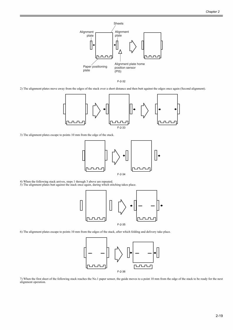
Chapter 2
2-19
F-2-32
2) The alignment plates move away from the edges of the stack over a short distance and then butt against the edges once again (Second alignment).
F-2-33
3) The alignment plates escape to points 10 mm from the edge of the stack.
F-2-34
4) When the following stack arrives, steps 1 through 3 above are repeated.5) The alignment plates butt against the stack once again, during which stitching takes place.
F-2-35
6) The alignment plates escape to points 10 mm from the edges of the stack, after which folding and delivery take place.
F-2-36
7) When the first sheet of the following stack reaches the No.1 paper sensor, the guide moves to a point 10 mm from the edge of the stack to be ready for the nextalignment operation.
Sheets
Paper positioning plate
Alignmentplate
Alignmentplate
Alignment plate home position sensor(PI5)
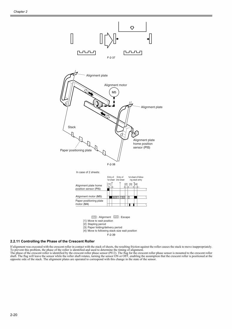
Chapter 2
2-20
F-2-37
F-2-38
F-2-39
2.2.11 Controlling the Phase of the Crescent Roller0023-6402
If alignment was executed with the crescent roller in contact with the stack of sheets, the resulting friction against the roller causes the stack to move inappropriately.To prevent this problem, the phase of the roller is identified and used to determine the timing of alignment.The phase of the crescent roller is identified by the crescent roller phase sensor (PI12). The flag for the crescent roller phase sensor is mounted to the crescent rollershaft. The flag will leave the sensor while the roller shaft rotates, turning the sensor ON or OFF, enabling the assumption that the crescent roller is positioned at theopposite side of the stack. The alignment plates are operated to correspond with this change in the state of the sensor.
M5
Alignment motor
Alignment plate
Alignment plate
Alignment plate home position sensor (PI5)
Stack
Paper positioning plate
Alignment plate home position sensor (PI5)
Paper positioning plate motor (M4)
Alignment motor (M5)
: Alignment : Escape
Entry of 1st sheet
Entry of 2nd sheet
1st sheet of follow-ing stack entry
In case of 2 sheets:
[1]: Move to wait position[2]: Stapling period[3]: Paper folding/delivery period[4]: Move to following stack size wait position
[1] [2] [3] [4]
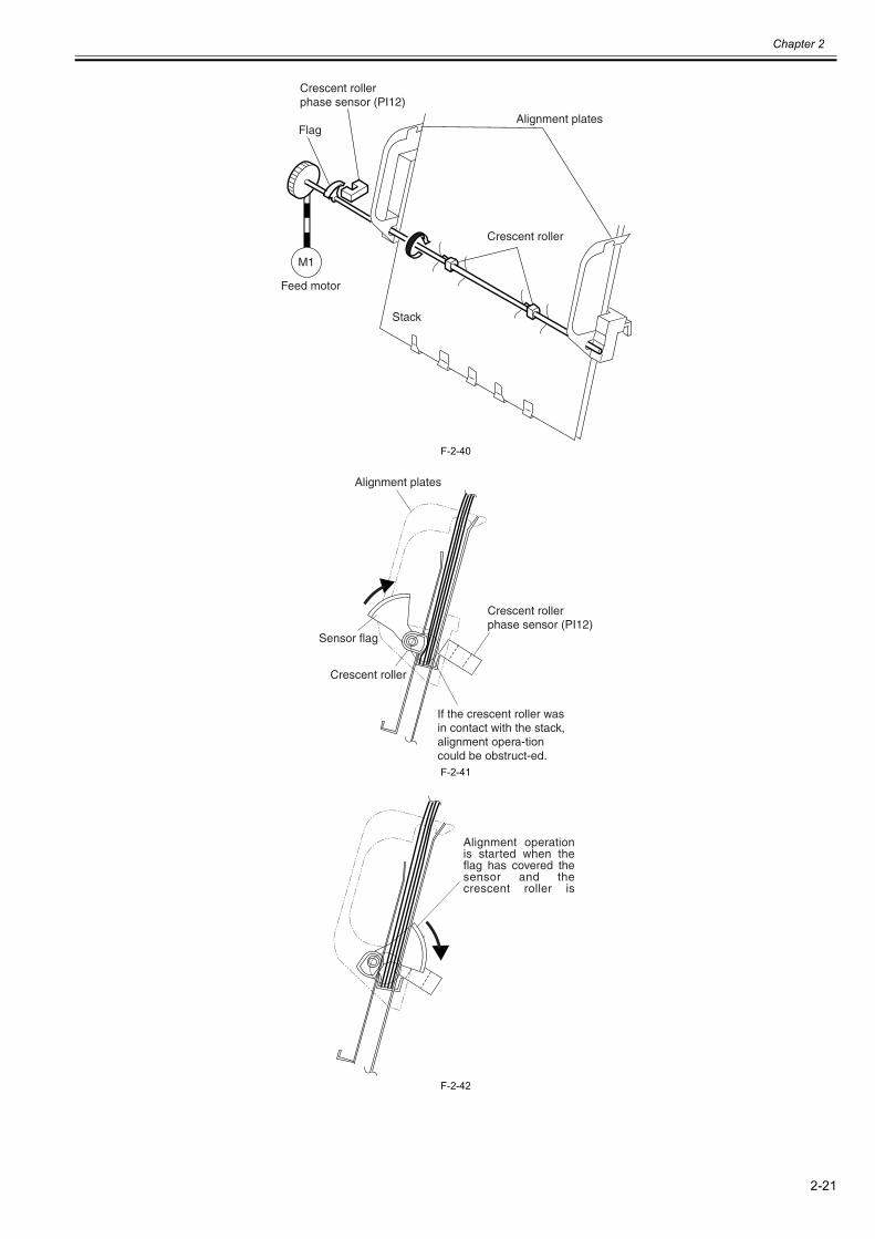
Chapter 2
2-21
F-2-40
F-2-41
F-2-42
Crescent roller phase sensor (PI12)
Flag
Feed motor
Stack
Crescent roller
Alignment plates
M1
Alignment plates
Crescent roller phase sensor (PI12)
If the crescent roller was in contact with the stack, alignment opera-tion could be obstruct-ed.
Sensor flag
Crescent roller
Alignment operation is started when the flag has covered the sensor and the crescent roller is
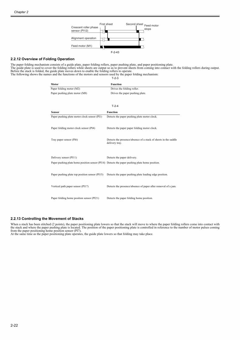
Chapter 2
2-22
F-2-43
2.2.12 Overview of Folding Operation0023-6403
The paper folding mechanism consists of a guide plate, paper folding rollers, paper pushing plate, and paper positioning plate.The guide plate is used to cover the folding rollers while sheets are output so as to prevent sheets from coming into contact with the folding rollers during output.Before the stack is folded, the guide plate moves down to enable the folding rollers to operate.The following shows the names and the functions of the motors and sensors used by the paper folding mechanism:
T-2-3
T-2-4
2.2.13 Controlling the Movement of Stacks0023-6404
When a stack has been stitched (2 points), the paper positioning plate lowers so that the stack will move to where the paper folding rollers come into contact withthe stack and where the paper pushing plate is located. The position of the paper positioning plate is controlled in reference to the number of motor pulses comingfrom the paper positioning home position sensor (PI7).At the same time as the paper positioning plate operates, the guide plate lowers so that folding may take place.
Motor FunctionPaper folding motor (M2) Drives the folding roller.Paper pushing plate motor (M8) Drives the paper pushing plate.
Sensor FunctionPaper pushing plate motor clock sensor (PI1) Detects the paper pushing plate motor clock.
Paper folding motor clock sensor (PI4) Detects the paper paper folding motor clock.
Tray paper sensor (PI6) Detects the presence/absence of a stack of sheets in the saddle delivery tray.
Delivery sensor (PI11) Detects the paper delivery.
Paper pushing plate home position sensor (PI14) Detects the paper pushing plate home position.
Paper pushing plate top position sensor (PI15) Detects the paper pushing plate leading edge position.
Vertical path paper sensor (PI17) Detects the presence/absence of paper after removal of a jam.
Paper folding home position sensor (PI21) Detects the paper folding home position.
Crescent roller phase sensor (PI12)
First sheet Second sheet Feed motor stops
Alignment operation
Feed motor (M1)
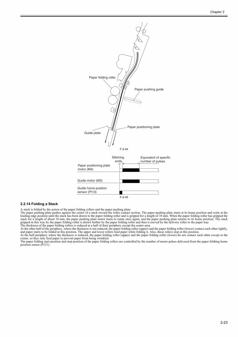
Chapter 2
2-23
F-2-44
F-2-45
2.2.14 Folding a Stack0023-6405
A stack is folded by the action of the paper folding rollers and the paper pushing plate.The paper pushing plate pushes against the center of a stack toward the roller contact section. The paper pushing plate starts at its home position and waits at theleading edge position until the stack has been drawn to the paper folding roller and is gripped for a length of 10 mm. When the paper folding roller has gripped thestack for a length of about 10 mm, the paper pushing plate motor starts to rotate once again, and the paper pushing plate returns to its home position. The stackgripped in this way by the paper folding roller is drawn further by the paper folding roller and then is moved by the delivery roller to the paper tray.The thickness of the paper folding rollers is reduced at a half of their periphery except the center area. At the other half of the periphery, where the thickness is not reduced, the paper folding roller (upper) and the paper folding roller (lower) contact each other tightly,and paper starts to be folded at this position. The upper and lower rollers feed paper while folding it. Also, these rollers stop at this position.At the half periphery where the thickness is reduced, the paper folding roller (upper) and the paper folding roller (lower) do not contact each other except at thecenter, so they only feed paper to prevent paper from being wrinkled.The paper folding start position and stop position of the paper folding rollers are controlled by the number of motor pulses delivered from the paper foldimg homeposition sensor (P121).
Paper folding roller
Guide plate
Paper positioning plate
Paper pushing guide
Stitching ends
Equivalent of specific number of pulses
Paper positioning plate motor (M4)
Guide motor (M3)
Guide home position sensor (PI13)
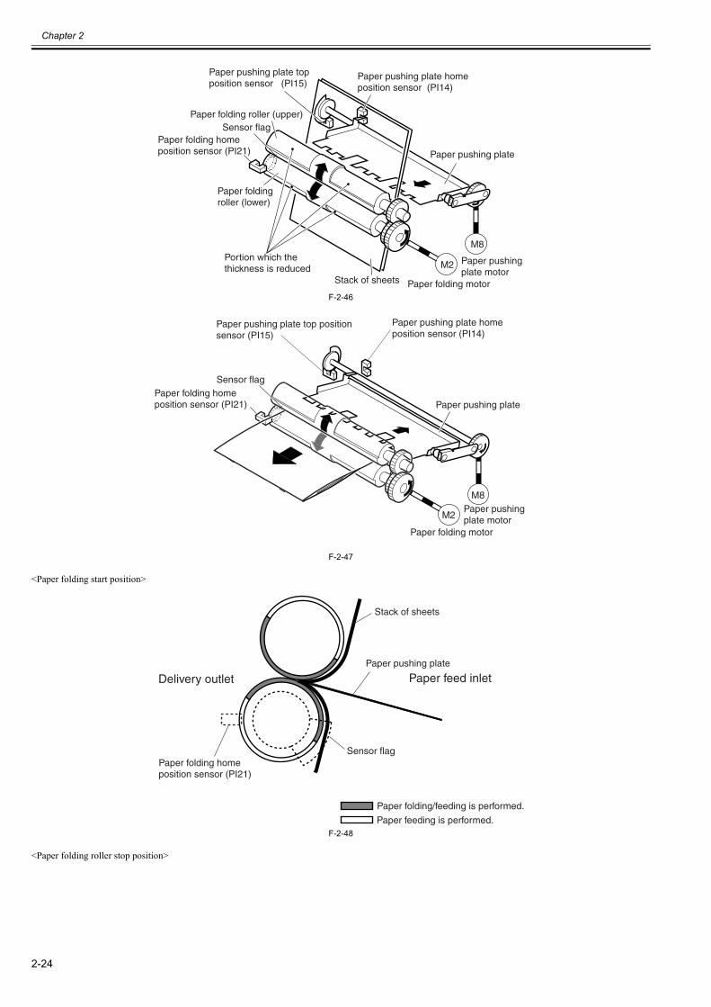
Chapter 2
2-24
F-2-46
F-2-47
<Paper folding start position>
F-2-48
<Paper folding roller stop position>
Paper folding roller (lower)
Paper folding roller (upper)Sensor flag
Paper folding home position sensor (PI21)
Paper pushing plate top position sensor (PI15)
Paper pushing plate home position sensor (PI14)
Paper pushing plate
Paper pushing plate motor
Paper folding motorStack of sheets
M2
M8Portion which the thickness is reduced
Sensor flagPaper folding home position sensor (PI21)
Paper pushing plate top position sensor (PI15)
Paper pushing plate home position sensor (PI14)
Paper pushing plate
Paper pushing plate motor
Paper folding motor
M2
M8
Paper folding/feeding is performed.
Paper feeding is performed.
Paper folding home position sensor (PI21)
Sensor flag
Delivery outlet Paper feed inletPaper pushing plate
Stack of sheets
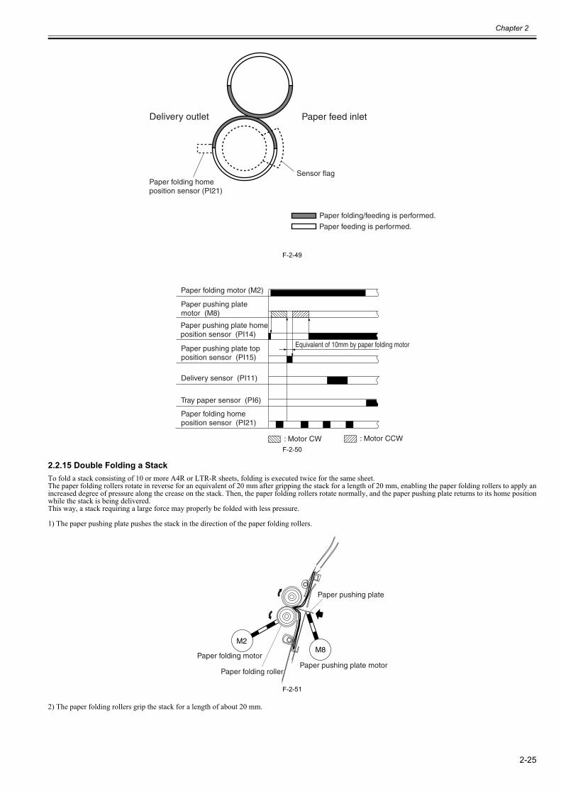
Chapter 2
2-25
F-2-49
F-2-50
2.2.15 Double Folding a Stack0023-6406
To fold a stack consisting of 10 or more A4R or LTR-R sheets, folding is executed twice for the same sheet.The paper folding rollers rotate in reverse for an equivalent of 20 mm after gripping the stack for a length of 20 mm, enabling the paper folding rollers to apply anincreased degree of pressure along the crease on the stack. Then, the paper folding rollers rotate normally, and the paper pushing plate returns to its home positionwhile the stack is being delivered.This way, a stack requiring a large force may properly be folded with less pressure.
1) The paper pushing plate pushes the stack in the direction of the paper folding rollers.
F-2-51
2) The paper folding rollers grip the stack for a length of about 20 mm.
Paper folding/feeding is performed.
Paper feeding is performed.
Paper folding home position sensor (PI21)
Sensor flag
Delivery outlet Paper feed inlet
Paper folding motor (M2)
Paper pushing plate motor (M8)
Paper pushing plate home position sensor (PI14)
Paper pushing plate top position sensor (PI15)
Delivery sensor (PI11)
Tray paper sensor (PI6)
: Motor CW : Motor CCW
Paper folding home position sensor (PI21)
Equivalent of 10mm by paper folding motor
M2
Paper folding motorM8
Paper pushing plate motor
Paper pushing plate
Paper folding roller
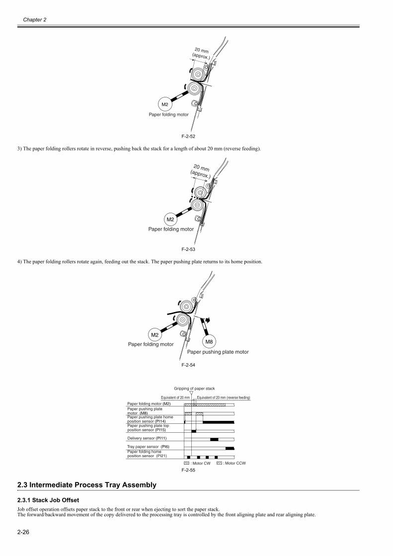
Chapter 2
2-26
F-2-52
3) The paper folding rollers rotate in reverse, pushing back the stack for a length of about 20 mm (reverse feeding).
F-2-53
4) The paper folding rollers rotate again, feeding out the stack. The paper pushing plate returns to its home position.
F-2-54
F-2-55
2.3 Intermediate Process Tray Assembly
2.3.1 Stack Job Offset0023-6407
Job offset operation offsets paper stack to the front or rear when ejecting to sort the paper stack.The forward/backward movement of the copy delivered to the processing tray is controlled by the front aligning plate and rear aligning plate.
M2
Paper folding motor
20 mm (approx.)
M2
Paper folding motor
20 mm (approx.)
M2
Paper folding motor M8
Paper pushing plate motor
Paper folding motor (M2)Paper pushing plate motor (M8)
Delivery sensor (PI11)
Paper pushing plate top position sensor (PI15)
Paper pushing plate home position sensor (PI14)
Tray paper sensor (PI6)
Equivalent of 20 mm Equivalent of 20 mm (reverse feeding)
Gripping of paper stack
: Motor CW : Motor CCW
Paper folding home position sensor (PI21)
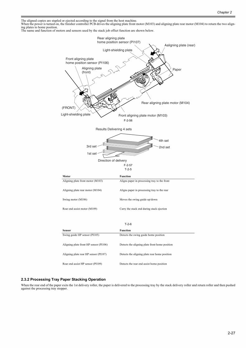
Chapter 2
2-27
The aligned copies are stapled or ejected according to the signal from the host machine.When the power is turned on, the finisher controller PCB drives the aligning plate front motor (M103) and aligning plate rear motor (M104) to return the two align-ing plates to home position.The name and function of motors and sensors used by the stack job offset function are shown below.
F-2-56
F-2-57T-2-5
T-2-6
2.3.2 Processing Tray Paper Stacking Operation0023-6408
When the rear end of the paper exits the 1st delivery roller, the paper is delivered to the processing tray by the stack delivery roller and return roller and then pushedagainst the processing tray stopper.
Motor FunctionAligning plate front motor (M103) Aligns paper in processing tray to the front
Aligning plate rear motor (M104) Aligns paper in processing tray to the rear
Swing motor (M106) Moves the swing guide up/down
Rear end assist motor (M109) Carry the stack end during stack ejection
Sensor FunctionSwing guide HP sensor (PI105) Detects the swing guide home position
Aligning plate front HP sensor (PI106) Detects the aligning plate front home position
Aligning plate rear HP sensor (PI107) Detects the aligning plate rear home position
Rear end assist HP sensor (PI109) Detects the rear end assist home position
Paper
Light-shielding plate
Rear aligning platehome position sensor (PI107)
Front aligning platehome position sensor (PI106)
Light-shielding plate
(FRONT)
Front aligning plate motor (M103)
Rear aligning plate motor (M104)
Aligning plate(front)
Aaligning plate (rear)
Results Delivering 4 sets
Direction of delivery
1st set
2nd set3rd set
4th set
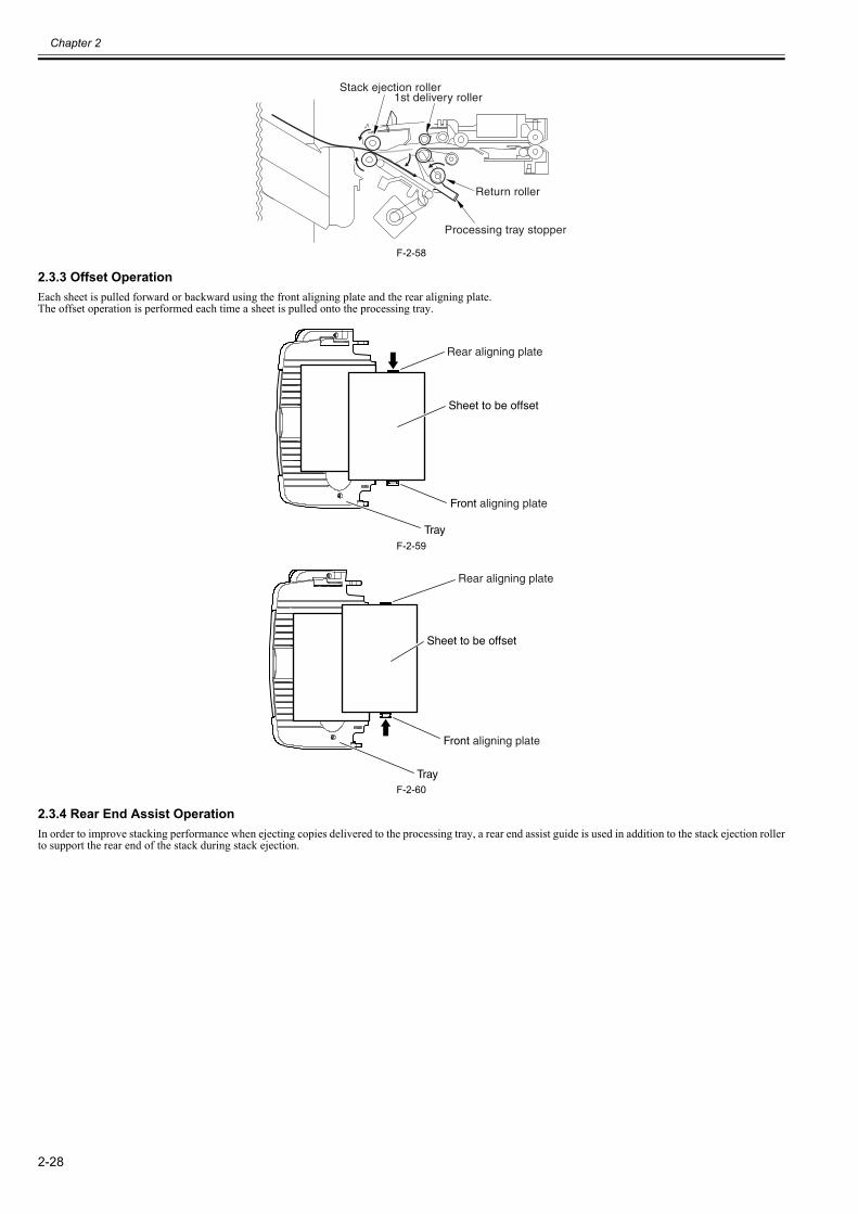
Chapter 2
2-28
F-2-58
2.3.3 Offset Operation0023-6409
Each sheet is pulled forward or backward using the front aligning plate and the rear aligning plate.The offset operation is performed each time a sheet is pulled onto the processing tray.
F-2-59
F-2-60
2.3.4 Rear End Assist Operation0023-6410
In order to improve stacking performance when ejecting copies delivered to the processing tray, a rear end assist guide is used in addition to the stack ejection rollerto support the rear end of the stack during stack ejection.
Stack ejection roller1st delivery roller
Return roller
Processing tray stopper
Rear aligning plate
Sheet to be offset
Front aligning plate
Tray
Rear aligning plate
Sheet to be offset
Front aligning plate
Tray
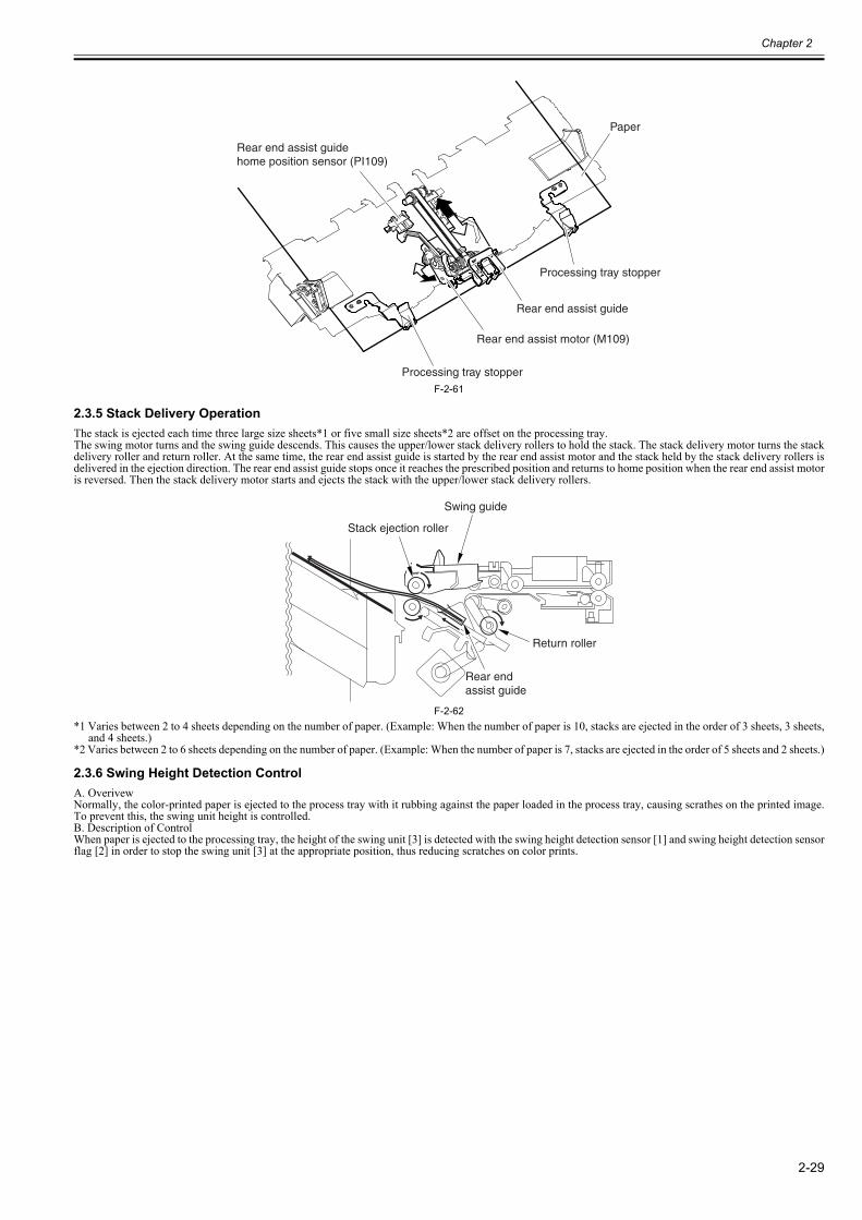
Chapter 2
2-29
F-2-61
2.3.5 Stack Delivery Operation0023-6411
The stack is ejected each time three large size sheets*1 or five small size sheets*2 are offset on the processing tray.The swing motor turns and the swing guide descends. This causes the upper/lower stack delivery rollers to hold the stack. The stack delivery motor turns the stackdelivery roller and return roller. At the same time, the rear end assist guide is started by the rear end assist motor and the stack held by the stack delivery rollers isdelivered in the ejection direction. The rear end assist guide stops once it reaches the prescribed position and returns to home position when the rear end assist motoris reversed. Then the stack delivery motor starts and ejects the stack with the upper/lower stack delivery rollers.
F-2-62*1 Varies between 2 to 4 sheets depending on the number of paper. (Example: When the number of paper is 10, stacks are ejected in the order of 3 sheets, 3 sheets,
and 4 sheets.)*2 Varies between 2 to 6 sheets depending on the number of paper. (Example: When the number of paper is 7, stacks are ejected in the order of 5 sheets and 2 sheets.)
2.3.6 Swing Height Detection Control0023-6412
A. OverivewNormally, the color-printed paper is ejected to the process tray with it rubbing against the paper loaded in the process tray, causing scrathes on the printed image.To prevent this, the swing unit height is controlled.B. Description of ControlWhen paper is ejected to the processing tray, the height of the swing unit [3] is detected with the swing height detection sensor [1] and swing height detection sensorflag [2] in order to stop the swing unit [3] at the appropriate position, thus reducing scratches on color prints.
Paper
Processing tray stopper
Rear end assist guide
Rear end assist motor (M109)
Processing tray stopper
Rear end assist guidehome position sensor (PI109)
Rear end assist guide
Return roller
Stack ejection roller
Swing guide
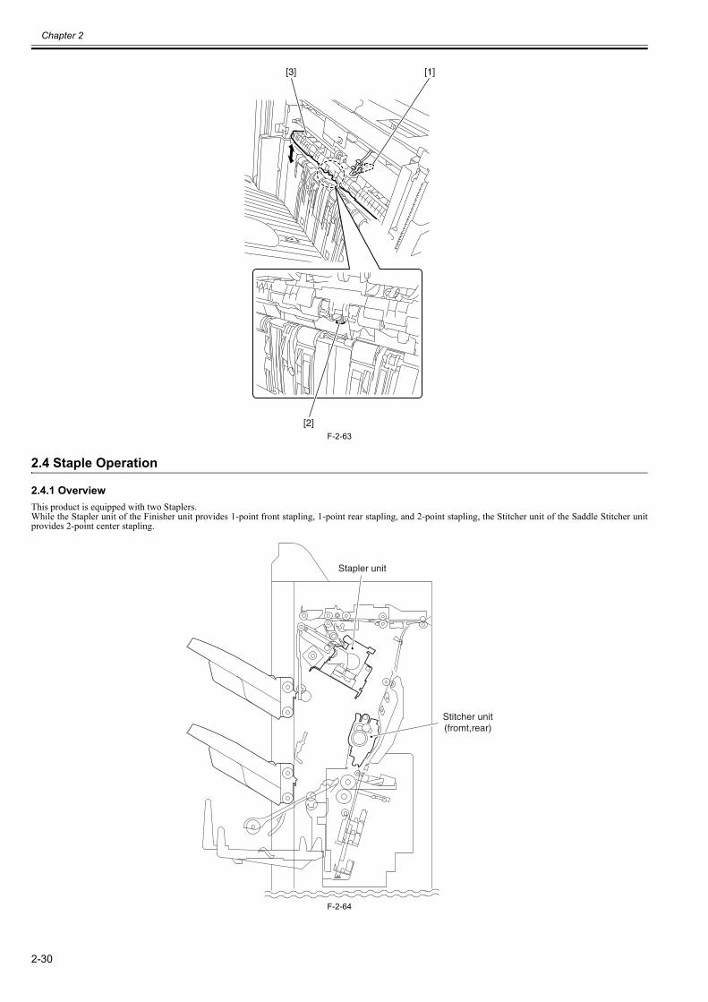
Chapter 2
2-30
F-2-63
2.4 Staple Operation
2.4.1 Overview0023-6413
This product is equipped with two Staplers.While the Stapler unit of the Finisher unit provides 1-point front stapling, 1-point rear stapling, and 2-point stapling, the Stitcher unit of the Saddle Stitcher unitprovides 2-point center stapling.
F-2-64
[1]
[2]
[3]
Stapler unit
Stitcher unit(fromt,rear)
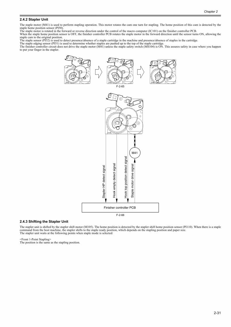
Chapter 2
2-31
2.4.2 Stapler Unit0023-6414
The staple motor (M41) is used to perform stapling operation. This motor rotates the cam one turn for stapling. The home position of this cam is detected by thestaple home position sensor (PI50).The staple motor is rotated in the forward or reverse direction under the control of the macro computer (IC101) on the finisher controller PCB.When the staple home position sensor is OFF, the finisher controller PCB rotates the staple motor in the forward direction until the sensor turns ON, allowing thestaple cam to the original position.The staple sensor (PI52) is used to detect presence/absence of a staple cartridge in the machine and presence/absence of staples in the cartridge.The staple edging sensor (PI51) is used to determine whether staples are pushed up to the top of the staple cartridge.The finisher controller circuit does not drive the staple motor (M41) unless the staple safety switch (MS104) is ON. This assures safety in case where you happento put your finger in the stapler.
F-2-65
F-2-66
2.4.3 Shifting the Stapler Unit0023-6415
The stapler unit is shifted by the stapler shift motor (M105). The home position is detected by the stapler shift home position sensor (PI110). When there is a staplecommand from the host machine, the stapler shifts to the staple ready position, which depends on the stapling position and paper size.The stapler unit waits at the following points when staple mode is selected:
<Front 1-Point Stapling>The position is the same as the stapling position.
M41
Sta
ple
mot
or d
rive
sign
al
Sta
pler
HP
det
ect s
igna
l
Hoo
k to
p po
sitio
n de
tect
sig
nal
Hoo
k em
pty
dete
ct s
igna
l
Finisher controller PCB
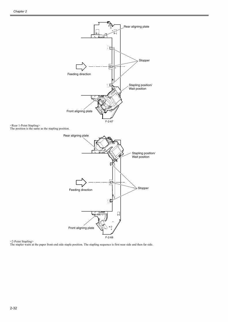
Chapter 2
2-32
F-2-67<Rear 1-Point Stapling>The position is the same as the stapling position.
F-2-68<2-Point Stapling>The stapler waits at the paper front end side staple position. The stapling sequence is first near side and then far side.
Front aligning plate
Stopper
Stapling position/Wait position
Feeding direction
Rear aligning plate
Front aligning plate
Stopper
Stapling position/Wait position
Feeding direction
Rear aligning plate
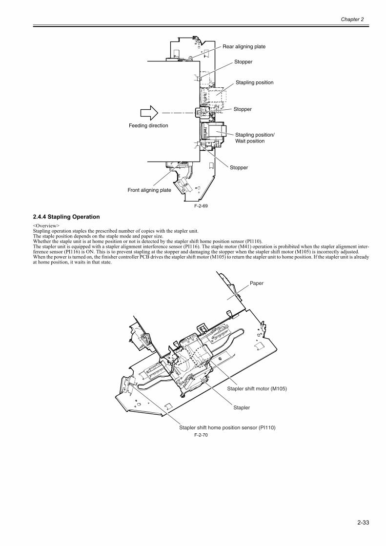
Chapter 2
2-33
F-2-69
2.4.4 Stapling Operation0023-6416
<Overview>Stapling operation staples the prescribed number of copies with the stapler unit.The staple position depends on the staple mode and paper size.Whether the staple unit is at home position or not is detected by the stapler shift home position sensor (PI110).The stapler unit is equipped with a stapler alignment interference sensor (PI116). The staple motor (M41) operation is prohibited when the stapler alignment inter-ference sensor (PI116) is ON. This is to prevent stapling at the stopper and damaging the stopper when the stapler shift motor (M105) is incorrectly adjusted.When the power is turned on, the finisher controller PCB drives the stapler shift motor (M105) to return the stapler unit to home position. If the stapler unit is alreadyat home position, it waits in that state.
F-2-70
Front aligning plate
Stopper
Stopper
Stopper
Stapling position/Wait position
Feeding direction
Rear aligning plate
Stapling position
Stapler shift motor (M105)
Paper
Stapler
Stapler shift home position sensor (PI110)
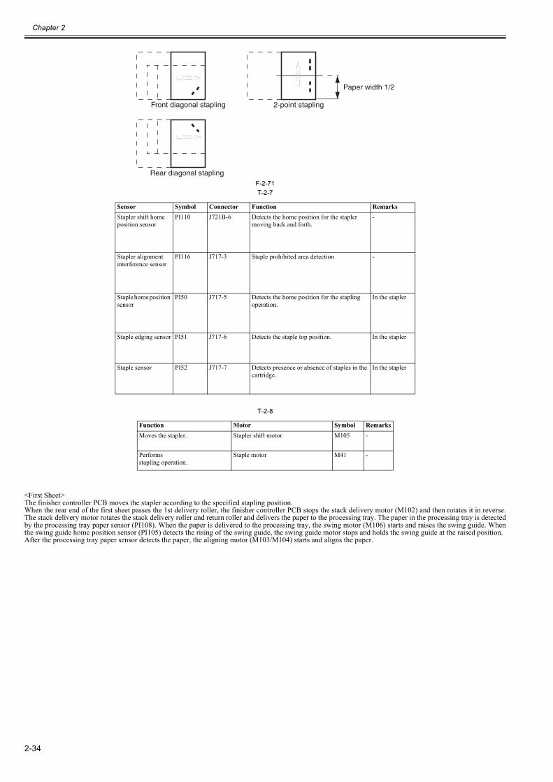
Chapter 2
2-34
F-2-71T-2-7
T-2-8
<First Sheet>The finisher controller PCB moves the stapler according to the specified stapling position.When the rear end of the first sheet passes the 1st delivery roller, the finisher controller PCB stops the stack delivery motor (M102) and then rotates it in reverse.The stack delivery motor rotates the stack delivery roller and return roller and delivers the paper to the processing tray. The paper in the processing tray is detectedby the processing tray paper sensor (PI108). When the paper is delivered to the processing tray, the swing motor (M106) starts and raises the swing guide. Whenthe swing guide home position sensor (PI105) detects the rising of the swing guide, the swing guide motor stops and holds the swing guide at the raised position.After the processing tray paper sensor detects the paper, the aligning motor (M103/M104) starts and aligns the paper.
Sensor Symbol Connector Function RemarksStapler shift home position sensor
PI110 J721B-6 Detects the home position for the stapler moving back and forth.
-
Stapler alignment interference sensor
PI116 J717-3 Staple prohibited area detection -
Staple home position sensor
PI50 J717-5 Detects the home position for the stapling operation.
In the stapler
Staple edging sensor PI51 J717-6 Detects the staple top position. In the stapler
Staple sensor PI52 J717-7 Detects presence or absence of staples in the cartridge.
In the stapler
Function Motor Symbol RemarksMoves the stapler. Stapler shift motor M105 -
Performsstapling operation.
Staple motor M41 -
Front diagonal stapling
Rear diagonal stapling
2-point stapling
Paper width 1/2
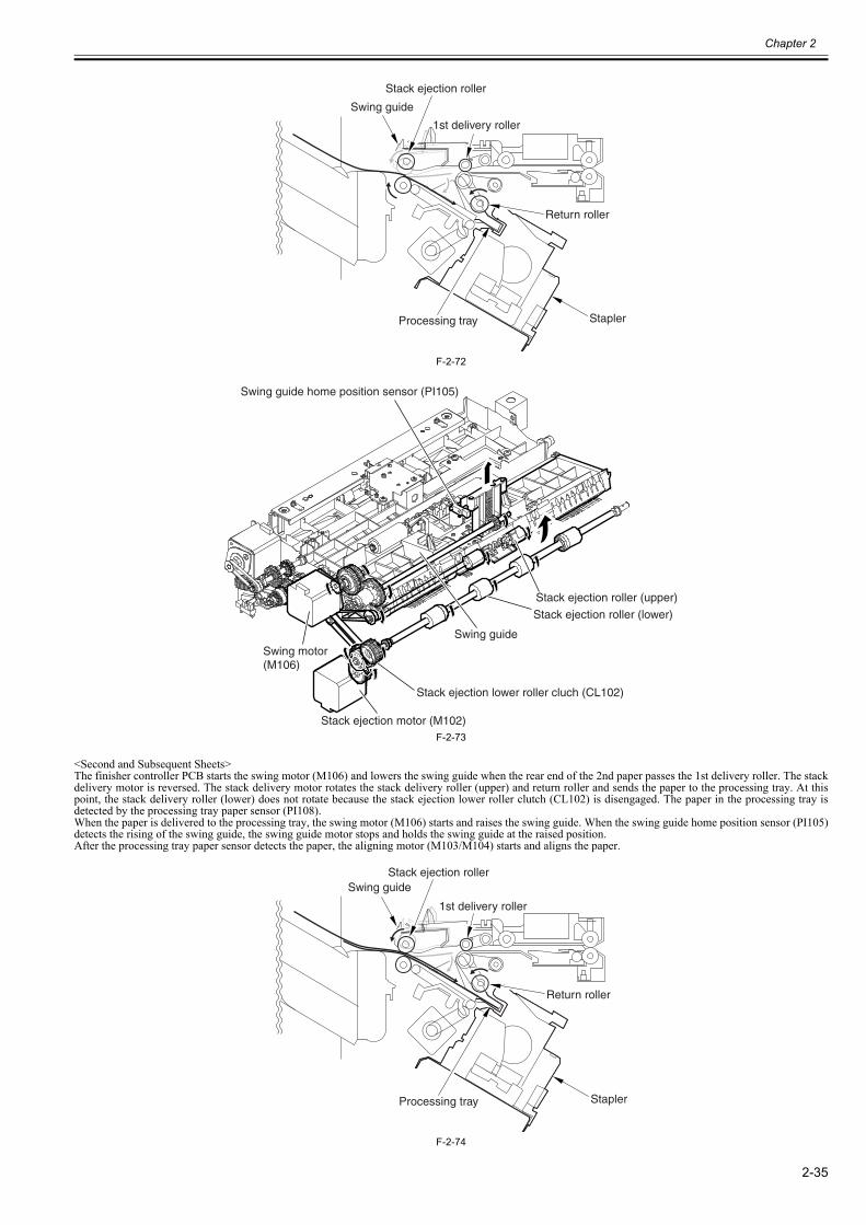
Chapter 2
2-35
F-2-72
F-2-73
<Second and Subsequent Sheets>The finisher controller PCB starts the swing motor (M106) and lowers the swing guide when the rear end of the 2nd paper passes the 1st delivery roller. The stackdelivery motor is reversed. The stack delivery motor rotates the stack delivery roller (upper) and return roller and sends the paper to the processing tray. At thispoint, the stack delivery roller (lower) does not rotate because the stack ejection lower roller clutch (CL102) is disengaged. The paper in the processing tray isdetected by the processing tray paper sensor (PI108).When the paper is delivered to the processing tray, the swing motor (M106) starts and raises the swing guide. When the swing guide home position sensor (PI105)detects the rising of the swing guide, the swing guide motor stops and holds the swing guide at the raised position.After the processing tray paper sensor detects the paper, the aligning motor (M103/M104) starts and aligns the paper.
F-2-74
Stapler
Return roller
Stack ejection roller
Swing guide
1st delivery roller
Processing tray
Swing guide
Swing motor (M106)
Stack ejection motor (M102)
Swing guide home position sensor (PI105)
Stack ejection lower roller cluch (CL102)
Stack ejection roller (lower)
Stack ejection roller (upper)
Stapler
Return roller
Stack ejection rollerSwing guide
1st delivery roller
Processing tray
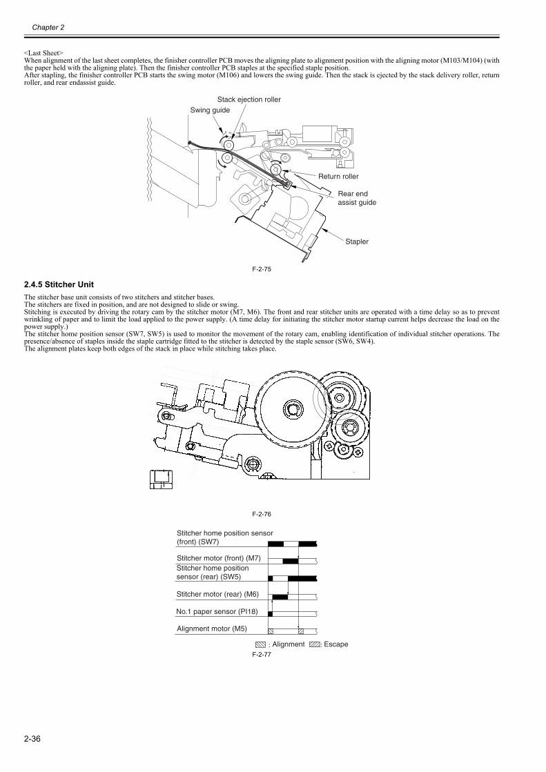
Chapter 2
2-36
<Last Sheet>When alignment of the last sheet completes, the finisher controller PCB moves the aligning plate to alignment position with the aligning motor (M103/M104) (withthe paper held with the aligning plate). Then the finisher controller PCB staples at the specified staple position.After stapling, the finisher controller PCB starts the swing motor (M106) and lowers the swing guide. Then the stack is ejected by the stack delivery roller, returnroller, and rear endassist guide.
F-2-75
2.4.5 Stitcher Unit0023-6417
The stitcher base unit consists of two stitchers and stitcher bases. The stitchers are fixed in position, and are not designed to slide or swing.Stitching is executed by driving the rotary cam by the stitcher motor (M7, M6). The front and rear stitcher units are operated with a time delay so as to preventwrinkling of paper and to limit the load applied to the power supply. (A time delay for initiating the stitcher motor startup current helps decrease the load on thepower supply.)The stitcher home position sensor (SW7, SW5) is used to monitor the movement of the rotary cam, enabling identification of individual stitcher operations. Thepresence/absence of staples inside the staple cartridge fitted to the stitcher is detected by the staple sensor (SW6, SW4).The alignment plates keep both edges of the stack in place while stitching takes place.
F-2-76
F-2-77
Rear end assist guide
Return roller
Stapler
Stack ejection roller
Swing guide
Stitcher home position sensor (front) (SW7)
Stitcher motor (front) (M7)
Stitcher motor (rear) (M6)
Stitcher home position sensor (rear) (SW5)
No.1 paper sensor (PI18)
Alignment motor (M5)
Alignment Escape
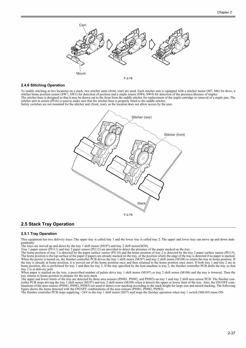
Chapter 2
2-37
F-2-78
2.4.6 Stitching Operation0023-6418
To enable stitching at two locations on a stack, two stitcher units (front, rear) are used. Each stitcher unit is equipped with a stitcher motor (M7, M6) for drive, astitcher home position sensor (SW7, SW5) for detection of position and a staple sensor (SW6, SW4) for detection of the presence/absence of staples.The stitcher base is designed so that it may be drawn out to the front from the saddle stitcher for replacement of the staple cartridge or removal of a staple jam. Thestitcher unit in sensor (PI16) is used to make sure that the stitcher base is properly fitted to the saddle stitcher.Safety switches are not mounted for the stitcher unit (front, rear), as the location does not allow access by the user.
F-2-79
2.5 Stack Tray Operation
2.5.1 Tray Operation0023-6419
This equipment has two delivery trays. The upper tray is called tray 1 and the lower tray is called tray 2. The upper and lower tray can move up and down inde-pendently.The trays are moved up and down by the tray 1 shift motor (M107) and tray 2 shift motor(M38).Tray 1 paper sensor (PI111) and tray 2 paper sensor (PI112) are provided to detect the presence of the paper stacked on the tray.The home position of tray 1 is detected by the paper surface sensor (PI114) and the home position of tray 2 is detected by the tray 2 paper surface sensor (PI115).The home position is the top surface of the paper if papers are already stacked on the tray, or the position where the edge of the tray is detected if no paper is stacked.When the power is turned on, the finisher controller PCB drives the tray 1 shift motor (M107) and tray 2 shift motor (M108) to return the tray to home position. Ifthe tray is already at home position, it is moved out of the home position once and then returned to the home position once more. If both tray 1 and tray 2 are athome position, this is performed for tray 1 and then for tray 2. If the tray specified by the host machine is tray 2, the finisher controller PCB shifts the tray so thattray 2 is at delivery port.When paper is stacked on the tray, a prescribed number of pulses drive tray 1 shift motor (M107) or tray 2 shift motor (M108) and the tray is lowered. Then thetray returns to home position to prepare for the next stack.The upper and lower limits of the tray are detected by three area sensors (PS981, PS982, and PS983) on tray 1 and tray 2 shift area sensor PCB. The finisher con-troller PCB stops driving the tray 1 shift motor (M107) and tray 2 shift motor (M108) when it detects the upper or lower limit of the tray. Also, the ON/OFF com-binations of the area sensors (PS981, PS982, PS983) are used to detect over-stacking according to the stack height for large size and mixed stacking. The followingfigure shows the items detected with the ON/OFF combinations of the area sensors (PS981, PS982, PS983).The finisher controller PCB stops supplying +24V to the tray 1 shift motor (M37) and stops the finisher operation when tray 1 switch (MS103) turns ON.
Cam
Mount
Stitcher (rear)
Stitcher (front)
Stack
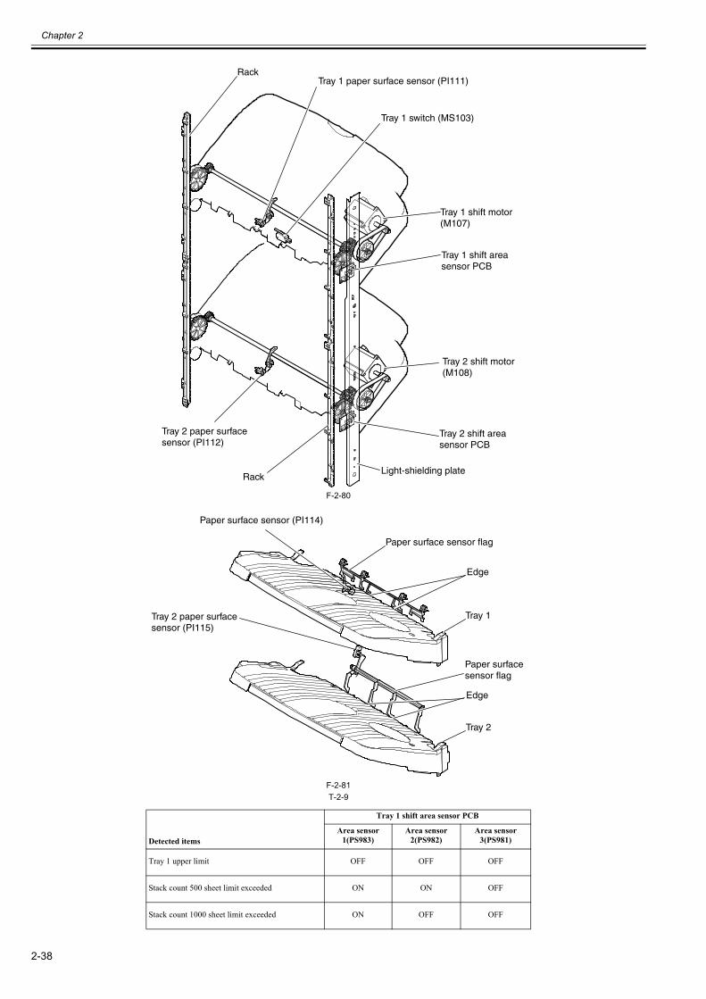
Chapter 2
2-38
F-2-80
F-2-81T-2-9
Detected items
Tray 1 shift area sensor PCB
Area sensor 1(PS983)
Area sensor 2(PS982)
Area sensor 3(PS981)
Tray 1 upper limit OFF OFF OFF
Stack count 500 sheet limit exceeded ON ON OFF
Stack count 1000 sheet limit exceeded ON OFF OFF
Tray 1 switch (MS103)
Tray 1 shift motor(M107)
Rack
Tray 2 shift motor(M108)
Tray 1 shift area sensor PCB
Tray 2 shift area sensor PCB
Tray 1 paper surface sensor (PI111)
Tray 2 paper surfacesensor (PI112)
RackLight-shielding plate
Tray 1
Paper surface sensor (PI114)
Edge
Tray 2
Tray 2 paper surfacesensor (PI115)
Edge
Paper surface sensor flag
Paper surface sensor flag
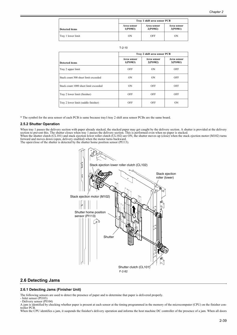
Chapter 2
2-39
T-2-10
* The symbol for the area sensor of each PCB is same because tray1/tray 2 shift area sensor PCBs are the same board.
2.5.2 Shutter Operation0023-6420
When tray 1 passes the delivery section with paper already stacked, the stacked paper may get caught by the delivery section. A shutter is provided at the deliverysection to prevent this. The shutter closes when tray 1 passes the delivery section. This is performed even when no paper is stacked.When the shutter clutch (CL101) and stack ejection lower roller clutch (CL102) are ON, the shutter moves up (close) when the stack ejection motor (M102) turnsforward and moves down (open, delivery enabled) when the motor turns backward.The open/close of the shutter is detected by the shutter home position sensor (PI113).
F-2-82
2.6 Detecting Jams
2.6.1 Detecting Jams (Finisher Unit)0023-6421
The following sensors are used to detect the presence of paper and to determine that paper is delivered properly.- Inlet sensor (PI103)- Delivery sensor (PI104)A jam is identified by checking whether paper is present at each sensor at the timing programmed in the memory of the microcomputer (CPU) on the finisher con-troller PCB.When the CPU identifies a jam, it suspends the finisher's delivery operation and informs the host machine DC controller of the presence of a jam. When all doors
Tray 1 lower limit ON OFF ON
Detected items
Tray 2 shift area sensor PCB
Area sensor 1(PS983)
Area sensor 2(PS982)
Area sensor 3(PS981)
Tray 2 upper limit OFF ON OFF
Stack count 500 sheet limit exceeded ON ON OFF
Stack count 1000 sheet limit exceeded ON OFF OFF
Tray 2 lower limit (finisher) OFF OFF OFF
Tray 2 lower limit (saddle finisher) OFF OFF ON
Detected items
Tray 1 shift area sensor PCB
Area sensor 1(PS983)
Area sensor 2(PS982)
Area sensor 3(PS981)
Shutter clutch (CL101)
Stack ejection motor (M102)
Shutter home positionsensor (PI113)
Stack ejection lower roller clutch (CL102)
Shutter
Stack ejection roller (lower)
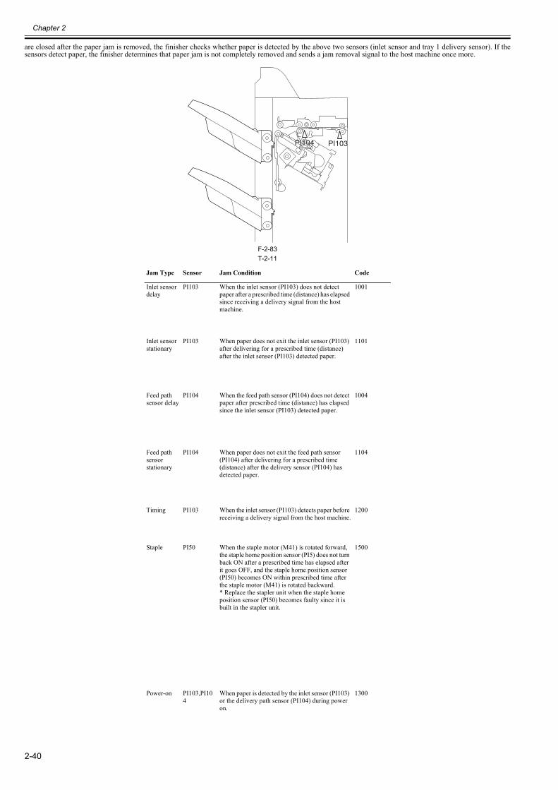
Chapter 2
2-40
are closed after the paper jam is removed, the finisher checks whether paper is detected by the above two sensors (inlet sensor and tray 1 delivery sensor). If thesensors detect paper, the finisher determines that paper jam is not completely removed and sends a jam removal signal to the host machine once more.
F-2-83T-2-11
Jam Type Sensor Jam Condition Code
Inlet sensordelay
PI103 When the inlet sensor (PI103) does not detect paper after a prescribed time (distance) has elapsed since receiving a delivery signal from the host machine.
1001
Inlet sensorstationary
PI103 When paper does not exit the inlet sensor (PI103) after delivering for a prescribed time (distance) after the inlet sensor (PI103) detected paper.
1101
Feed path sensor delay
PI104 When the feed path sensor (PI104) does not detect paper after prescribed time (distance) has elapsed since the inlet sensor (PI103) detected paper.
1004
Feed path sensor stationary
PI104 When paper does not exit the feed path sensor (PI104) after delivering for a prescribed time (distance) after the delivery sensor (PI104) has detected paper.
1104
Timing PI103 When the inlet sensor (PI103) detects paper before receiving a delivery signal from the host machine.
1200
Staple PI50 When the staple motor (M41) is rotated forward, the staple home position sensor (PI5) does not turn back ON after a prescribed time has elapsed after it goes OFF, and the staple home position sensor (PI50) becomes ON within prescribed time after the staple motor (M41) is rotated backward.* Replace the stapler unit when the staple home position sensor (PI50) becomes faulty since it is built in the stapler unit.
1500
Power-on PI103,PI104
When paper is detected by the inlet sensor (PI103) or the delivery path sensor (PI104) during power on.
1300
PI104 PI103PI104 PI103
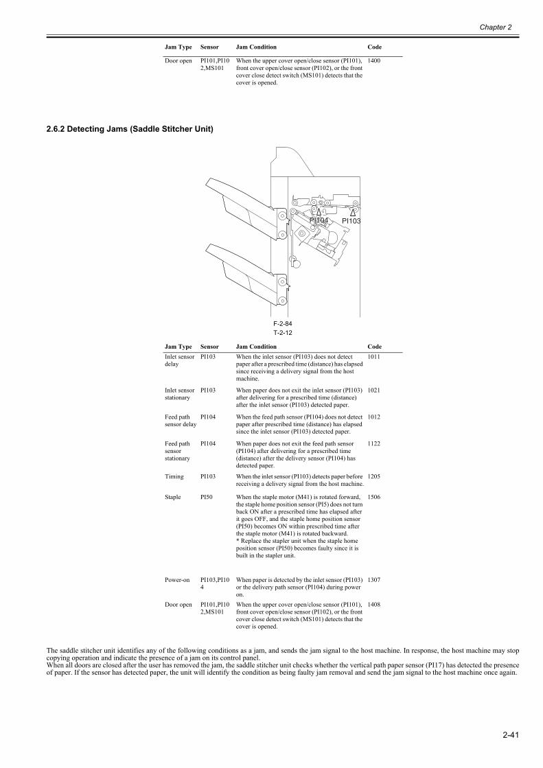
Chapter 2
2-41
2.6.2 Detecting Jams (Saddle Stitcher Unit)0023-6422
F-2-84T-2-12
The saddle stitcher unit identifies any of the following conditions as a jam, and sends the jam signal to the host machine. In response, the host machine may stopcopying operation and indicate the presence of a jam on its control panel.When all doors are closed after the user has removed the jam, the saddle stitcher unit checks whether the vertical path paper sensor (PI17) has detected the presenceof paper. If the sensor has detected paper, the unit will identify the condition as being faulty jam removal and send the jam signal to the host machine once again.
Door open PI101,PI102,MS101
When the upper cover open/close sensor (PI101), front cover open/close sensor (PI102), or the front cover close detect switch (MS101) detects that the cover is opened.
1400
Jam Type Sensor Jam Condition CodeInlet sensordelay
PI103 When the inlet sensor (PI103) does not detect paper after a prescribed time (distance) has elapsed since receiving a delivery signal from the host machine.
1011
Inlet sensorstationary
PI103 When paper does not exit the inlet sensor (PI103) after delivering for a prescribed time (distance) after the inlet sensor (PI103) detected paper.
1021
Feed path sensor delay
PI104 When the feed path sensor (PI104) does not detect paper after prescribed time (distance) has elapsed since the inlet sensor (PI103) detected paper.
1012
Feed path sensor stationary
PI104 When paper does not exit the feed path sensor (PI104) after delivering for a prescribed time (distance) after the delivery sensor (PI104) has detected paper.
1122
Timing PI103 When the inlet sensor (PI103) detects paper before receiving a delivery signal from the host machine.
1205
Staple PI50 When the staple motor (M41) is rotated forward, the staple home position sensor (PI5) does not turn back ON after a prescribed time has elapsed after it goes OFF, and the staple home position sensor (PI50) becomes ON within prescribed time after the staple motor (M41) is rotated backward.* Replace the stapler unit when the staple home position sensor (PI50) becomes faulty since it is built in the stapler unit.
1506
Power-on PI103,PI104
When paper is detected by the inlet sensor (PI103) or the delivery path sensor (PI104) during power on.
1307
Door open PI101,PI102,MS101
When the upper cover open/close sensor (PI101), front cover open/close sensor (PI102), or the front cover close detect switch (MS101) detects that the cover is opened.
1408
Jam Type Sensor Jam Condition Code
PI104 PI103PI104 PI103
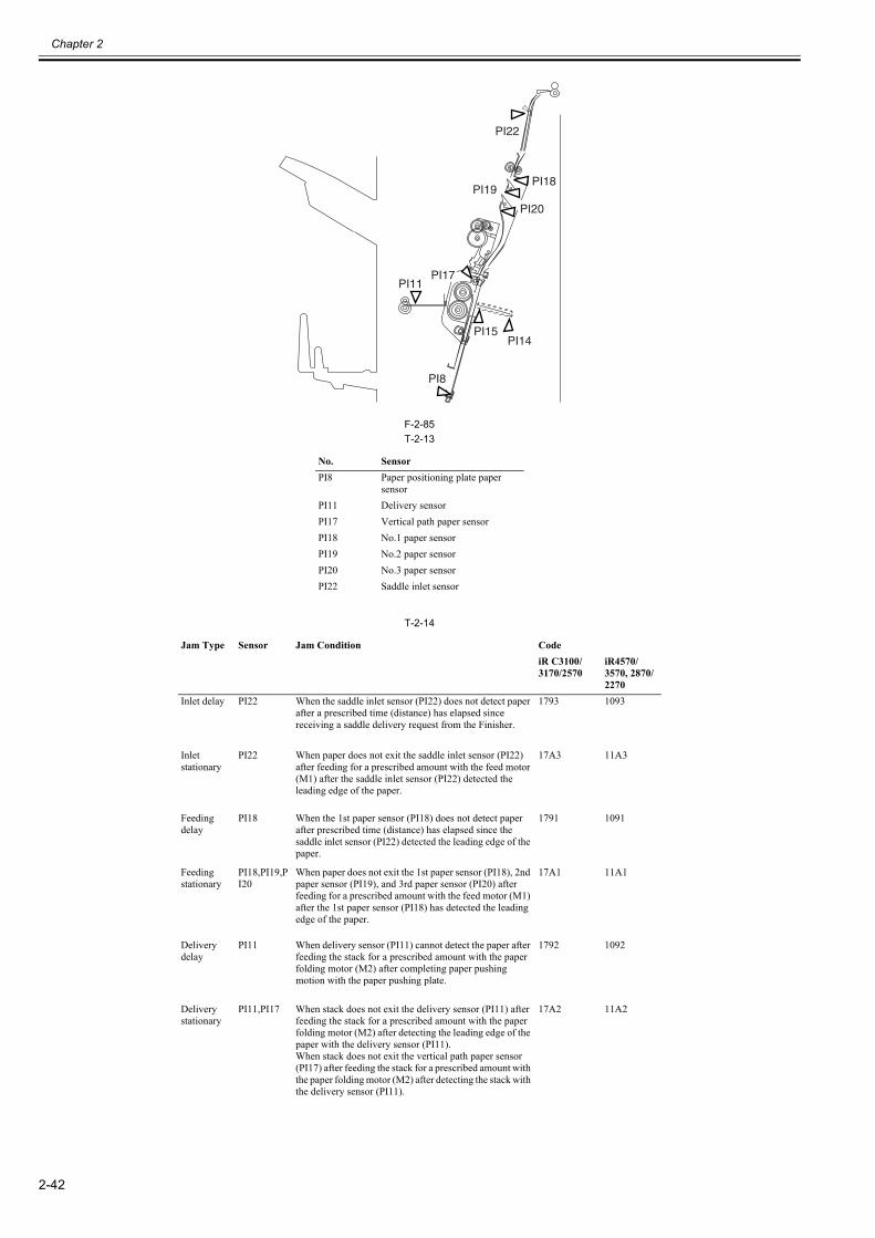
Chapter 2
2-42
F-2-85T-2-13
T-2-14
No. SensorPI8 Paper positioning plate paper
sensorPI11 Delivery sensorPI17 Vertical path paper sensorPI18 No.1 paper sensorPI19 No.2 paper sensorPI20 No.3 paper sensorPI22 Saddle inlet sensor
Jam Type Sensor Jam Condition CodeiR C3100/3170/2570
iR4570/3570, 2870/2270
Inlet delay PI22 When the saddle inlet sensor (PI22) does not detect paper after a prescribed time (distance) has elapsed since receiving a saddle delivery request from the Finisher.
1793 1093
Inlet stationary
PI22 When paper does not exit the saddle inlet sensor (PI22) after feeding for a prescribed amount with the feed motor (M1) after the saddle inlet sensor (PI22) detected the leading edge of the paper.
17A3 11A3
Feeding delay
PI18 When the 1st paper sensor (PI18) does not detect paper after prescribed time (distance) has elapsed since the saddle inlet sensor (PI22) detected the leading edge of the paper.
1791 1091
Feeding stationary
PI18,PI19,PI20
When paper does not exit the 1st paper sensor (PI18), 2nd paper sensor (PI19), and 3rd paper sensor (PI20) after feeding for a prescribed amount with the feed motor (M1) after the 1st paper sensor (PI18) has detected the leading edge of the paper.
17A1 11A1
Delivery delay
PI11 When delivery sensor (PI11) cannot detect the paper after feeding the stack for a prescribed amount with the paper folding motor (M2) after completing paper pushing motion with the paper pushing plate.
1792 1092
Delivery stationary
PI11,PI17 When stack does not exit the delivery sensor (PI11) after feeding the stack for a prescribed amount with the paper folding motor (M2) after detecting the leading edge of the paper with the delivery sensor (PI11).When stack does not exit the vertical path paper sensor (PI17) after feeding the stack for a prescribed amount with the paper folding motor (M2) after detecting the stack with the delivery sensor (PI11).
17A2 11A2
PI19PI18
PI15PI14
PI8
PI11
PI20
PI17
PI22
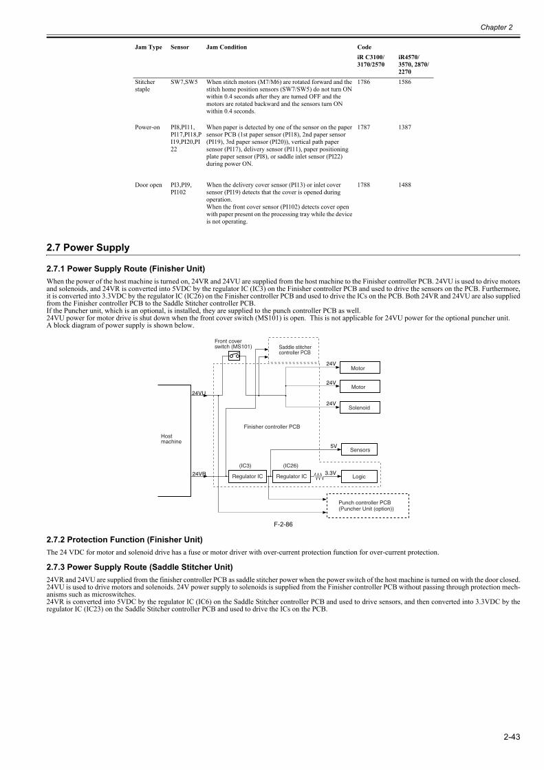
Chapter 2
2-43
2.7 Power Supply
2.7.1 Power Supply Route (Finisher Unit)0023-6423
When the power of the host machine is turned on, 24VR and 24VU are supplied from the host machine to the Finisher controller PCB. 24VU is used to drive motorsand solenoids, and 24VR is converted into 5VDC by the regulator IC (IC3) on the Finisher controller PCB and used to drive the sensors on the PCB. Furthermore,it is converted into 3.3VDC by the regulator IC (IC26) on the Finisher controller PCB and used to drive the ICs on the PCB. Both 24VR and 24VU are also suppliedfrom the Finisher controller PCB to the Saddle Stitcher controller PCB.If the Puncher unit, which is an optional, is installed, they are supplied to the punch controller PCB as well. 24VU power for motor drive is shut down when the front cover switch (MS101) is open. This is not applicable for 24VU power for the optional puncher unit.A block diagram of power supply is shown below.
F-2-86
2.7.2 Protection Function (Finisher Unit)0023-6425
The 24 VDC for motor and solenoid drive has a fuse or motor driver with over-current protection function for over-current protection.
2.7.3 Power Supply Route (Saddle Stitcher Unit)0023-6427
24VR and 24VU are supplied from the finisher controller PCB as saddle stitcher power when the power switch of the host machine is turned on with the door closed.24VU is used to drive motors and solenoids. 24V power supply to solenoids is supplied from the Finisher controller PCB without passing through protection mech-anisms such as microswitches. 24VR is converted into 5VDC by the regulator IC (IC6) on the Saddle Stitcher controller PCB and used to drive sensors, and then converted into 3.3VDC by theregulator IC (IC23) on the Saddle Stitcher controller PCB and used to drive the ICs on the PCB.
Stitcher staple
SW7,SW5 When stitch motors (M7/M6) are rotated forward and the stitch home position sensors (SW7/SW5) do not turn ON within 0.4 seconds after they are turned OFF and the motors are rotated backward and the sensors turn ON within 0.4 seconds.
1786 1586
Power-on PI8,PI11,PI17,PI18,PI19,PI20,PI22
When paper is detected by one of the sensor on the paper sensor PCB (1st paper sensor (PI18), 2nd paper sensor (PI19), 3rd paper sensor (PI20)), vertical path paper sensor (PI17), delivery sensor (PI11), paper positioning plate paper sensor (PI8), or saddle inlet sensor (PI22) during power ON.
1787 1387
Door open PI3,PI9,PI102
When the delivery cover sensor (PI13) or inlet cover sensor (PI19) detects that the cover is opened during operation.When the front cover sensor (PI102) detects cover open with paper present on the processing tray while the device is not operating.
1788 1488
Jam Type Sensor Jam Condition CodeiR C3100/3170/2570
iR4570/3570, 2870/2270
Saddle stitcher controller PCB
Front cover switch (MS101)
Finisher controller PCB
Punch controller PCB(Puncher Unit (option))
24VR
24VU
3.3V
5V
24V
24V
24VMotor
Solenoid
Sensors
Logic
Motor
(IC26)
Regulator IC
Host machine
(IC3)
Regulator IC
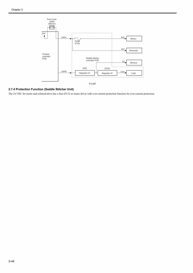
Chapter 2
2-44
F-2-87
2.7.4 Protection Function (Saddle Stitcher Unit)0023-7431
The 24 VDC for motor and solenoid drive has a fuse (FU3) or motor driver with over-current protection function for over-current protection.
24VR
24VU
24V
FUSE(FU3)
Front cover switch
(MS101)
Regulator IC
(IC6)
Regulator IC
(IC23)
3.3V
5V
Motors
Solenoids
Sensors
Logic
24V
24V
FinishercontrollerPCB Saddle stitcher
controller PCB

Chapter 3 Parts Replacement Procedure

Contents
Contents
3.1 External Covers..............................................................................................................................................................3-13.1.1 Front Cover .................................................................................................................................................................................. 3-1
3.1.1.1 Removing the Front Cover..............................................................................................................................................................................3-13.1.2 Rear Cover ................................................................................................................................................................................... 3-1
3.1.2.1 Removing the Rear Cover ...............................................................................................................................................................................3-13.1.3 Left Upper Cover ......................................................................................................................................................................... 3-1
3.1.3.1 Removing the Left Upper Cover.....................................................................................................................................................................3-13.1.4 Upper Door .................................................................................................................................................................................. 3-1
3.1.4.1 Removing the Upper Door ..............................................................................................................................................................................3-13.1.5 Grate-shaped Upper Guide .......................................................................................................................................................... 3-1
3.1.5.1 Removing the Grate-shaped Upper Guide ......................................................................................................................................................3-13.1.6 Grate-shaped Lower Guide .......................................................................................................................................................... 3-2
3.1.6.1 Removing the Grate-shaped Lower Guide......................................................................................................................................................3-23.1.7 Front Inside Upper Cover ............................................................................................................................................................ 3-2
3.1.7.1 Removing the Front Inside upper Cover .........................................................................................................................................................3-23.1.8 Front Inside Lower Cover ............................................................................................................................................................ 3-2
3.1.8.1 Removing the Front Inside Lower Cover........................................................................................................................................................3-23.1.9 PCB Cover ................................................................................................................................................................................... 3-2
3.1.9.1 Removing the PCB Cover...............................................................................................................................................................................3-23.2 Drive System..................................................................................................................................................................3-2
3.2.1 Stapler .......................................................................................................................................................................................... 3-23.2.1.1 Removing the Stapler ......................................................................................................................................................................................3-2
3.2.2 Swing Unit ................................................................................................................................................................................... 3-33.2.2.1 Removing the Processing Tray .......................................................................................................................................................................3-3
3.2.3 Saddle Unit................................................................................................................................................................................... 3-33.2.3.1 Removing the Saddle Unit ..............................................................................................................................................................................3-3
3.2.4 Stitcher Mount Unit ..................................................................................................................................................................... 3-43.2.4.1 Removing the Stitcher Mount Unit .................................................................................................................................................................3-4
3.2.5 Positioning Plate Unit .................................................................................................................................................................. 3-43.2.5.1 Removing the Saddle Stitcher Controller PCB...............................................................................................................................................3-4
3.3 Document Feeding System ............................................................................................................................................3-43.3.1 Process Tray Assembly................................................................................................................................................................ 3-4
3.3.1.1 Removing the Processing Tray .......................................................................................................................................................................3-43.3.2 Tray 1 ........................................................................................................................................................................................... 3-5
3.3.2.1 Removing the Tray 1.......................................................................................................................................................................................3-53.3.3 Tray 2 ........................................................................................................................................................................................... 3-6
3.3.3.1 Removing the Tray 2.......................................................................................................................................................................................3-63.3.4 Buffer Roller ................................................................................................................................................................................ 3-7
3.3.4.1 Removing the Buffer Roller............................................................................................................................................................................3-73.3.5 Return Roller................................................................................................................................................................................ 3-7
3.3.5.1 Removing the Return Roller ...........................................................................................................................................................................3-73.3.6 Return Roller Unit........................................................................................................................................................................ 3-7
3.3.6.1 Removing the Return Roller Unit ...................................................................................................................................................................3-73.3.7 Saddle Delivery Tray Unit ........................................................................................................................................................... 3-8
3.3.7.1 Removing the Saddle Delivery Tray Unit.......................................................................................................................................................3-83.3.8 Upper Delivery Guide.................................................................................................................................................................. 3-8
3.3.8.1 Removing the Upper Delivery Guide .............................................................................................................................................................3-83.3.9 Inlet Feed Unit ............................................................................................................................................................................. 3-8
3.3.9.1 Removing the Inlet Feed Unit .........................................................................................................................................................................3-83.3.10 Paper Folding Roller .................................................................................................................................................................. 3-9
3.3.10.1 Removing the Paper Folding Roller..............................................................................................................................................................3-93.3.11 No.1 Flapper ............................................................................................................................................................................ 3-10

Contents
3.3.11.1 Removing the No.1 Flappers ...................................................................................................................................................................... 3-103.3.12 No.2 Flapper ............................................................................................................................................................................ 3-10
3.3.12.1 Removing the No.2 Flappers ...................................................................................................................................................................... 3-103.4 Electrical System......................................................................................................................................................... 3-10
3.4.1 Finisher Controller PCB ............................................................................................................................................................ 3-103.4.1.1 Finisher Controller PCB ............................................................................................................................................................................... 3-10
3.4.1.1.1 Removing the Rear Cover..................................................................................................................................................................... 3-103.4.1.1.2 Removing the Finisher Controller PCB................................................................................................................................................ 3-11
3.4.2 Static Charge Eliminator 1......................................................................................................................................................... 3-113.4.2.1 Removing the Swing Unit Static Charge Eliminator.................................................................................................................................... 3-11
3.4.3 Static Charge Eliminator 2......................................................................................................................................................... 3-113.4.3.1 Removing the Inlet Static Charge Eliminator............................................................................................................................................... 3-11
3.4.4 Saddle Stitcher Controller PCB ................................................................................................................................................. 3-113.4.4.1 Removing the PCB Cover............................................................................................................................................................................. 3-113.4.4.2 Removing the Saddle Stitcher Controller PCB............................................................................................................................................. 3-12
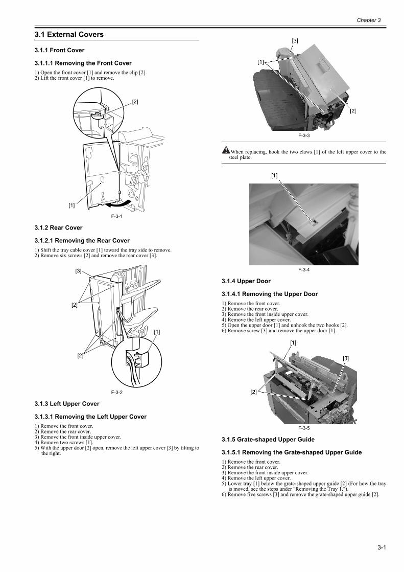
Chapter 3
3-1
3.1 External Covers
3.1.1 Front Cover
3.1.1.1 Removing the Front Cover0023-6428
1) Open the front cover [1] and remove the clip [2].2) Lift the front cover [1] to remove.
F-3-1
3.1.2 Rear Cover
3.1.2.1 Removing the Rear Cover0023-6430
1) Shift the tray cable cover [1] toward the tray side to remove.2) Remove six screws [2] and remove the rear cover [3].
F-3-2
3.1.3 Left Upper Cover
3.1.3.1 Removing the Left Upper Cover0023-6438
1) Remove the front cover.2) Remove the rear cover.3) Remove the front inside upper cover.4) Remove two screws [1].5) With the upper door [2] open, remove the left upper cover [3] by tilting to
the right.
F-3-3
When replacing, hook the two claws [1] of the left upper cover to thesteel plate.
F-3-4
3.1.4 Upper Door
3.1.4.1 Removing the Upper Door0023-6447
1) Remove the front cover.2) Remove the rear cover.3) Remove the front inside upper cover.4) Remove the left upper cover.5) Open the upper door [1] and unhook the two hooks [2].6) Remove screw [3] and remove the upper door [1].
F-3-5
3.1.5 Grate-shaped Upper Guide
3.1.5.1 Removing the Grate-shaped Upper Guide0023-6478
1) Remove the front cover.2) Remove the rear cover.3) Remove the front inside upper cover.4) Remove the left upper cover.5) Lower tray [1] below the grate-shaped upper guide [2] (For how the tray
is moved, see the steps under "Removing the Tray 1.").6) Remove five screws [3] and remove the grate-shaped upper guide [2].
[1]
[2]
[2]
[1]
[3]
[2]
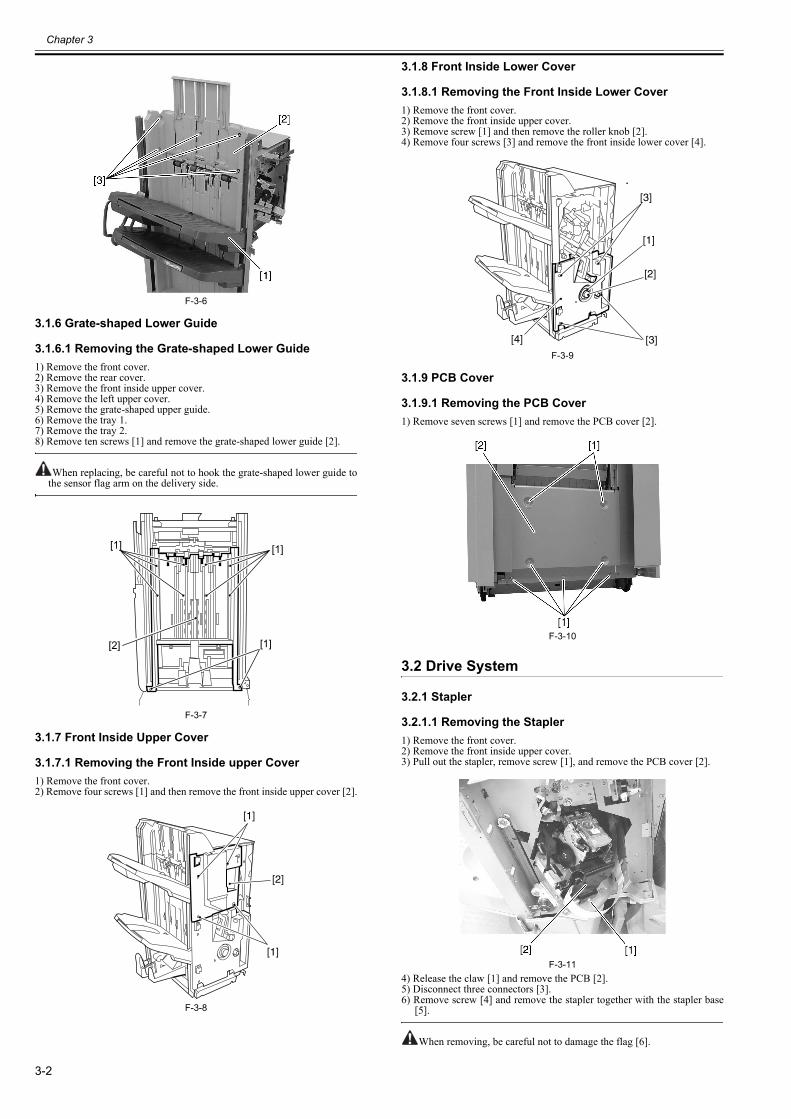
Chapter 3
3-2
F-3-6
3.1.6 Grate-shaped Lower Guide
3.1.6.1 Removing the Grate-shaped Lower Guide0023-6496
1) Remove the front cover.2) Remove the rear cover.3) Remove the front inside upper cover.4) Remove the left upper cover.5) Remove the grate-shaped upper guide. 6) Remove the tray 1.7) Remove the tray 2.8) Remove ten screws [1] and remove the grate-shaped lower guide [2].
When replacing, be careful not to hook the grate-shaped lower guide tothe sensor flag arm on the delivery side.
F-3-7
3.1.7 Front Inside Upper Cover
3.1.7.1 Removing the Front Inside upper Cover0023-6498
1) Remove the front cover.2) Remove four screws [1] and then remove the front inside upper cover [2].
F-3-8
3.1.8 Front Inside Lower Cover
3.1.8.1 Removing the Front Inside Lower Cover0023-6501
1) Remove the front cover.2) Remove the front inside upper cover.3) Remove screw [1] and then remove the roller knob [2].4) Remove four screws [3] and remove the front inside lower cover [4].
F-3-9
3.1.9 PCB Cover
3.1.9.1 Removing the PCB Cover0023-6503
1) Remove seven screws [1] and remove the PCB cover [2].
F-3-10
3.2 Drive System
3.2.1 Stapler
3.2.1.1 Removing the Stapler0023-6544
1) Remove the front cover.2) Remove the front inside upper cover.3) Pull out the stapler, remove screw [1], and remove the PCB cover [2].
F-3-114) Release the claw [1] and remove the PCB [2].5) Disconnect three connectors [3].6) Remove screw [4] and remove the stapler together with the stapler base
[5].
When removing, be careful not to damage the flag [6].
[1]
[1]
[1]
[2]
[1]
[2]
[1]
[3]
[2]
[3]
[1]
[4]
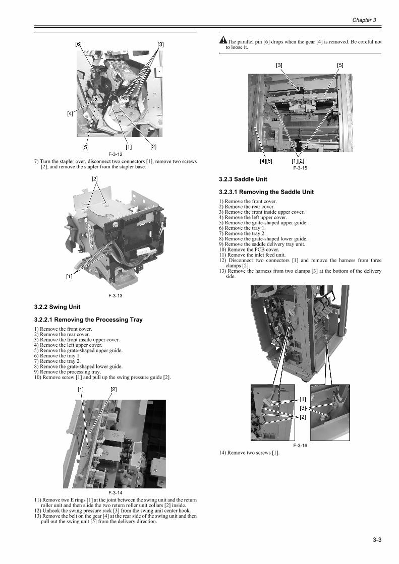
Chapter 3
3-3
F-3-127) Turn the stapler over, disconnect two connectors [1], remove two screws
[2], and remove the stapler from the stapler base.
F-3-13
3.2.2 Swing Unit
3.2.2.1 Removing the Processing Tray0023-6567
1) Remove the front cover.2) Remove the rear cover.3) Remove the front inside upper cover.4) Remove the left upper cover.5) Remove the grate-shaped upper guide.6) Remove the tray 1.7) Remove the tray 2.8) Remove the grate-shaped lower guide.9) Remove the processing tray. 10) Remove screw [1] and pull up the swing pressure guide [2].
F-3-1411) Remove two E rings [1] at the joint between the swing unit and the return
roller unit and then slide the two return roller unit collars [2] inside.12) Unhook the swing pressure rack [3] from the swing unit center hook.13) Remove the belt on the gear [4] at the rear side of the swing unit and then
pull out the swing unit [5] from the delivery direction.
The parallel pin [6] drops when the gear [4] is removed. Be coreful notto loose it.
F-3-15
3.2.3 Saddle Unit
3.2.3.1 Removing the Saddle Unit0023-6582
1) Remove the front cover.2) Remove the rear cover.3) Remove the front inside upper cover.4) Remove the left upper cover.5) Remove the grate-shaped upper guide.6) Remove the tray 1.7) Remove the tray 2.8) Remove the grate-shaped lower guide.9) Remove the saddle delivery tray unit.10) Remove the PCB cover. 11) Remove the inlet feed unit.12) Disconnect two connectors [1] and remove the harness from three
clamps [2].13) Remove the harness from two clamps [3] at the bottom of the delivery
side.
F-3-1614) Remove two screws [1].
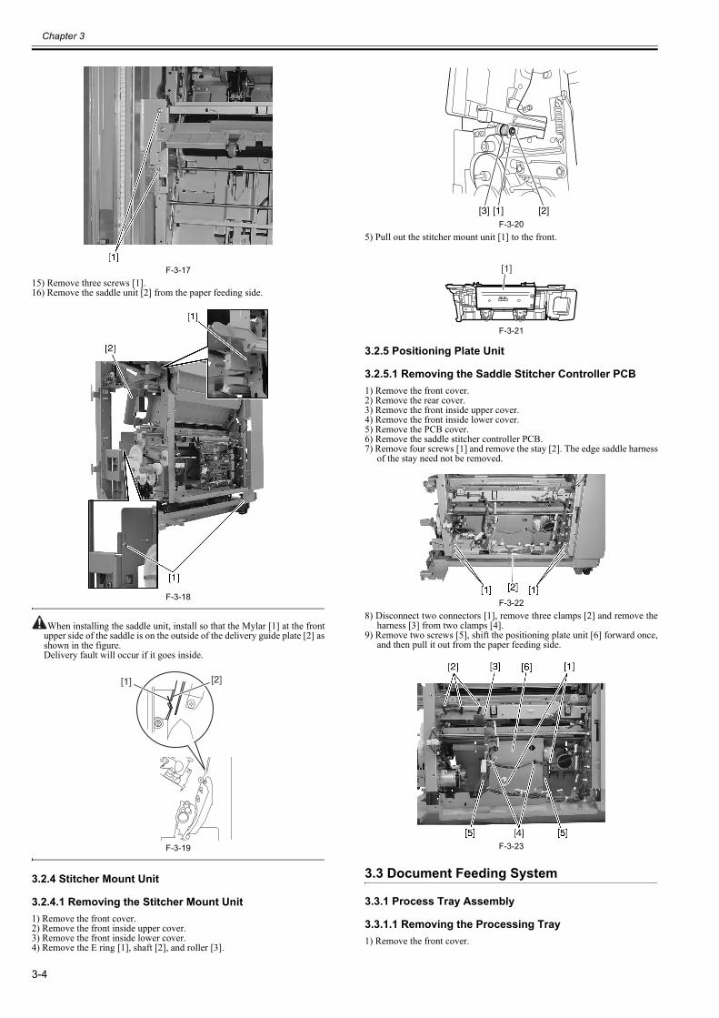
Chapter 3
3-4
F-3-1715) Remove three screws [1].16) Remove the saddle unit [2] from the paper feeding side.
F-3-18
When installing the saddle unit, install so that the Mylar [1] at the frontupper side of the saddle is on the outside of the delivery guide plate [2] asshown in the figure.Delivery fault will occur if it goes inside.
F-3-19
3.2.4 Stitcher Mount Unit
3.2.4.1 Removing the Stitcher Mount Unit0023-6586
1) Remove the front cover.2) Remove the front inside upper cover.3) Remove the front inside lower cover.4) Remove the E ring [1], shaft [2], and roller [3].
F-3-205) Pull out the stitcher mount unit [1] to the front.
F-3-21
3.2.5 Positioning Plate Unit
3.2.5.1 Removing the Saddle Stitcher Controller PCB0023-6593
1) Remove the front cover.2) Remove the rear cover.3) Remove the front inside upper cover.4) Remove the front inside lower cover.5) Remove the PCB cover.6) Remove the saddle stitcher controller PCB.7) Remove four screws [1] and remove the stay [2]. The edge saddle harness
of the stay need not be removed.
F-3-228) Disconnect two connectors [1], remove three clamps [2] and remove the
harness [3] from two clamps [4].9) Remove two screws [5], shift the positioning plate unit [6] forward once,
and then pull it out from the paper feeding side.
F-3-23
3.3 Document Feeding System
3.3.1 Process Tray Assembly
3.3.1.1 Removing the Processing Tray0023-6615
1) Remove the front cover.
[1] [2]
[1][3] [2]
[1]
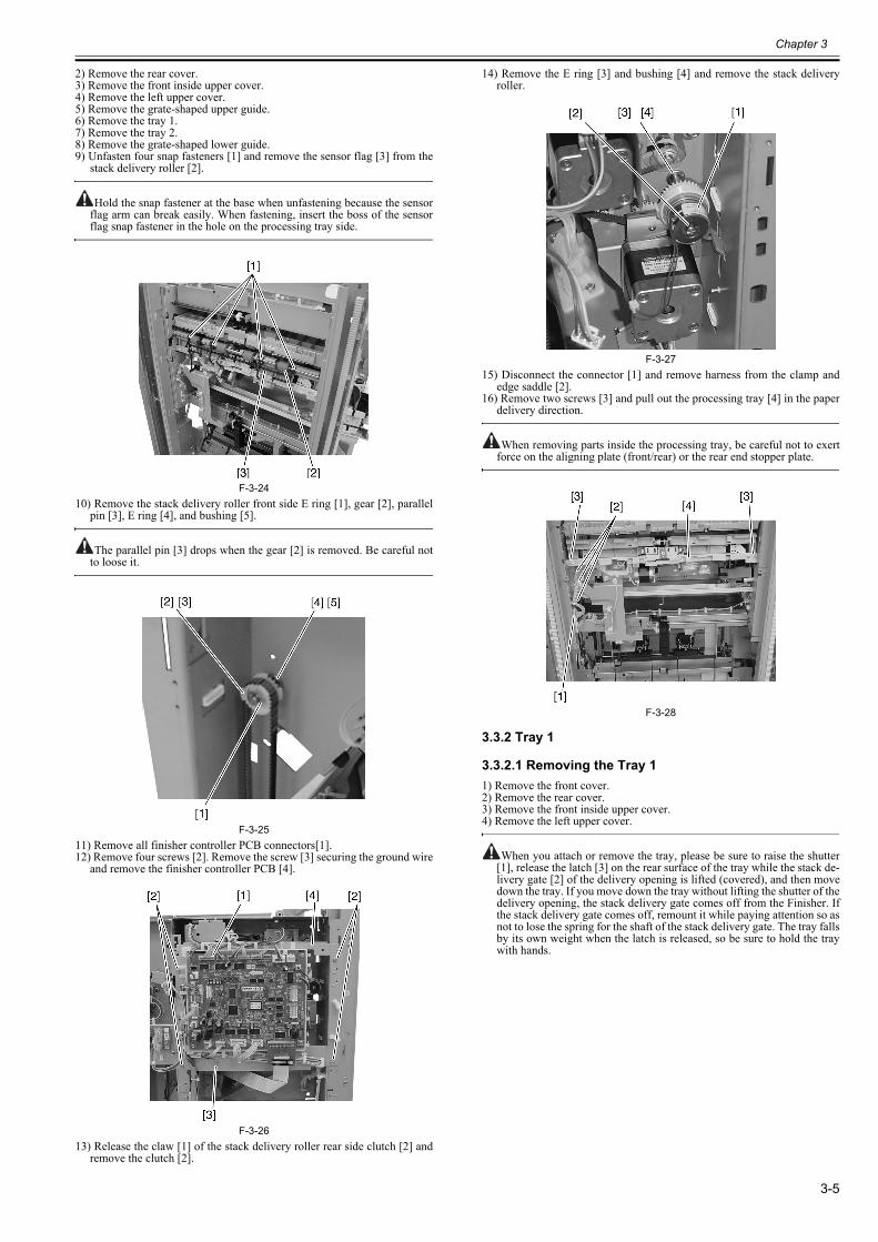
Chapter 3
3-5
2) Remove the rear cover.3) Remove the front inside upper cover.4) Remove the left upper cover.5) Remove the grate-shaped upper guide.6) Remove the tray 1.7) Remove the tray 2.8) Remove the grate-shaped lower guide.9) Unfasten four snap fasteners [1] and remove the sensor flag [3] from the
stack delivery roller [2].
Hold the snap fastener at the base when unfastening because the sensorflag arm can break easily. When fastening, insert the boss of the sensorflag snap fastener in the hole on the processing tray side.
F-3-2410) Remove the stack delivery roller front side E ring [1], gear [2], parallel
pin [3], E ring [4], and bushing [5].
The parallel pin [3] drops when the gear [2] is removed. Be careful notto loose it.
F-3-2511) Remove all finisher controller PCB connectors[1].12) Remove four screws [2]. Remove the screw [3] securing the ground wire
and remove the finisher controller PCB [4].
F-3-2613) Release the claw [1] of the stack delivery roller rear side clutch [2] and
remove the clutch [2].
14) Remove the E ring [3] and bushing [4] and remove the stack deliveryroller.
F-3-2715) Disconnect the connector [1] and remove harness from the clamp and
edge saddle [2].16) Remove two screws [3] and pull out the processing tray [4] in the paper
delivery direction.
When removing parts inside the processing tray, be careful not to exertforce on the aligning plate (front/rear) or the rear end stopper plate.
F-3-28
3.3.2 Tray 1
3.3.2.1 Removing the Tray 10023-6626
1) Remove the front cover.2) Remove the rear cover.3) Remove the front inside upper cover.4) Remove the left upper cover.
When you attach or remove the tray, please be sure to raise the shutter[1], release the latch [3] on the rear surface of the tray while the stack de-livery gate [2] of the delivery opening is lifted (covered), and then movedown the tray. If you move down the tray without lifting the shutter of thedelivery opening, the stack delivery gate comes off from the Finisher. Ifthe stack delivery gate comes off, remount it while paying attention so asnot to lose the spring for the shaft of the stack delivery gate. The tray fallsby its own weight when the latch is released, so be sure to hold the traywith hands.
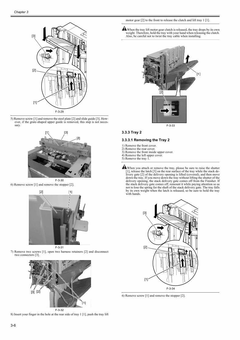
Chapter 3
3-6
F-3-29
5) Remove screw [1] and remove the steel plate [2] and slide guide [3]. How-ever, if the grate-shaped upper guide is removed, this step is not neces-sary.
F-3-306) Remove screw [1] and remove the stopper [2].
F-3-317) Remove two screws [1], open two harness retainers [2] and disconnect
two connectors [3].
F-3-328) Insert your finger in the hole at the rear side of tray 1 [1], push the tray lift
motor gear [2] to the front to release the clutch and lift tray 1 [1].
When the tray lift motor gear clutch is released, the tray drops by its ownweight. Therefore, hold the tray with your hand when releasing the clutch.Also, be careful not to twist the tray cable when installing.
F-3-33
3.3.3 Tray 2
3.3.3.1 Removing the Tray 20023-6637
1) Remove the front cover.2) Remove the rear cover.3) Remove the front inside upper cover.4) Remove the left upper cover.5) Remove the tray 1.
When you attach or remove the tray, please be sure to raise the shutter[1], release the latch [3] on the rear surface of the tray while the stack de-livery gate [2] of the delivery opening is lifted (covered), and then movedown the tray. If you move down the tray without lifting the shutter of thedelivery opening, the stack delivery gate comes off from the Finisher. Ifthe stack delivery gate comes off, remount it while paying attention so asnot to lose the spring for the shaft of the stack delivery gate. The tray fallsby its own weight when the latch is released, so be sure to hold the traywith hands.
F-3-34
6) Remove screw [1] and remove the stopper [2].
[3]
[2]
[1]
[3]
[2]
[1]
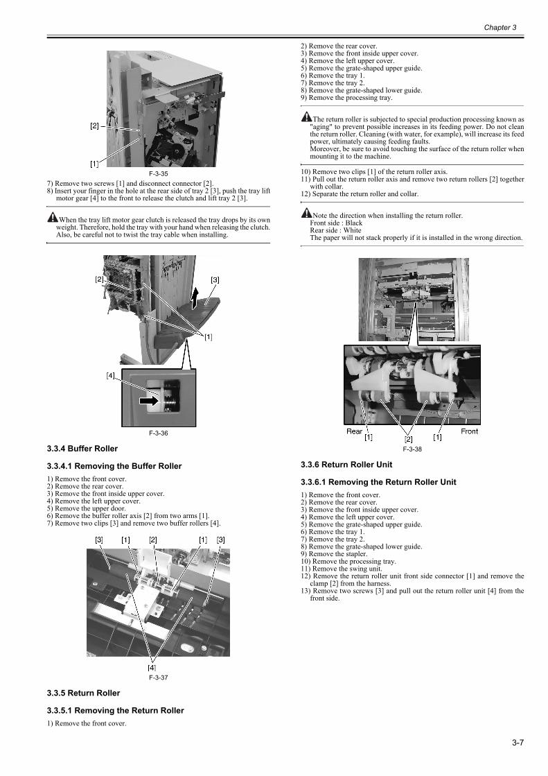
Chapter 3
3-7
F-3-357) Remove two screws [1] and disconnect connector [2].8) Insert your finger in the hole at the rear side of tray 2 [3], push the tray lift
motor gear [4] to the front to release the clutch and lift tray 2 [3].
When the tray lift motor gear clutch is released the tray drops by its ownweight. Therefore, hold the tray with your hand when releasing the clutch.Also, be careful not to twist the tray cable when installing.
F-3-36
3.3.4 Buffer Roller
3.3.4.1 Removing the Buffer Roller0023-6725
1) Remove the front cover.2) Remove the rear cover.3) Remove the front inside upper cover.4) Remove the left upper cover.5) Remove the upper door.6) Remove the buffer roller axis [2] from two arms [1].7) Remove two clips [3] and remove two buffer rollers [4].
F-3-37
3.3.5 Return Roller
3.3.5.1 Removing the Return Roller0023-6744
1) Remove the front cover.
2) Remove the rear cover.3) Remove the front inside upper cover.4) Remove the left upper cover.5) Remove the grate-shaped upper guide.6) Remove the tray 1.7) Remove the tray 2.8) Remove the grate-shaped lower guide.9) Remove the processing tray.
The return roller is subjected to special production processing known as"aging" to prevent possible increases in its feeding power. Do not cleanthe return roller. Cleaning (with water, for example), will increase its feedpower, ultimately causing feeding faults.Moreover, be sure to avoid touching the surface of the return roller whenmounting it to the machine.
10) Remove two clips [1] of the return roller axis.11) Pull out the return roller axis and remove two return rollers [2] together
with collar.12) Separate the return roller and collar.
Note the direction when installing the return roller.Front side : BlackRear side : WhiteThe paper will not stack properly if it is installed in the wrong direction.
F-3-38
3.3.6 Return Roller Unit
3.3.6.1 Removing the Return Roller Unit0023-6767
1) Remove the front cover.2) Remove the rear cover.3) Remove the front inside upper cover.4) Remove the left upper cover.5) Remove the grate-shaped upper guide.6) Remove the tray 1.7) Remove the tray 2.8) Remove the grate-shaped lower guide.9) Remove the stapler.10) Remove the processing tray.11) Remove the swing unit.12) Remove the return roller unit front side connector [1] and remove the
clamp [2] from the harness.13) Remove two screws [3] and pull out the return roller unit [4] from the
front side.
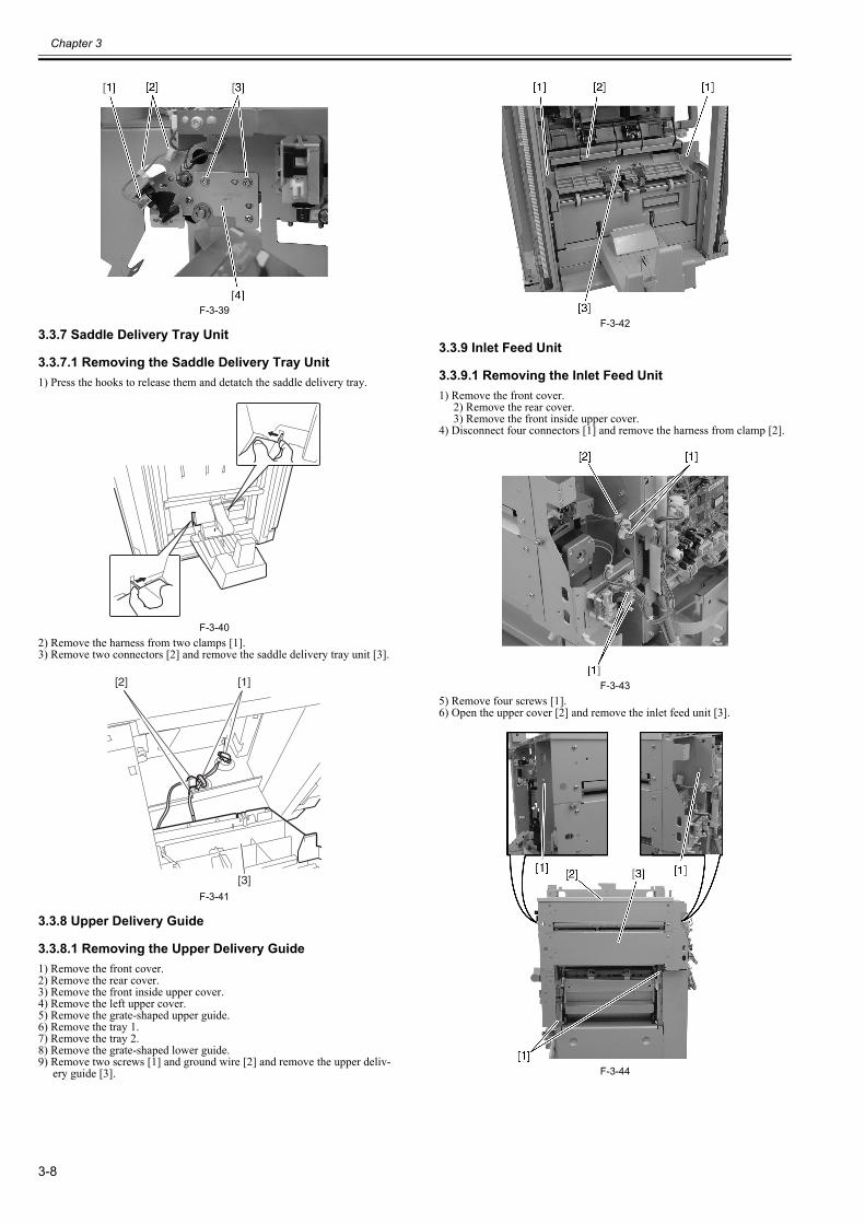
Chapter 3
3-8
F-3-39
3.3.7 Saddle Delivery Tray Unit
3.3.7.1 Removing the Saddle Delivery Tray Unit0023-6768
1) Press the hooks to release them and detatch the saddle delivery tray.
F-3-402) Remove the harness from two clamps [1].3) Remove two connectors [2] and remove the saddle delivery tray unit [3].
F-3-41
3.3.8 Upper Delivery Guide
3.3.8.1 Removing the Upper Delivery Guide0023-6778
1) Remove the front cover.2) Remove the rear cover.3) Remove the front inside upper cover.4) Remove the left upper cover.5) Remove the grate-shaped upper guide.6) Remove the tray 1.7) Remove the tray 2.8) Remove the grate-shaped lower guide.9) Remove two screws [1] and ground wire [2] and remove the upper deliv-
ery guide [3].
F-3-42
3.3.9 Inlet Feed Unit
3.3.9.1 Removing the Inlet Feed Unit0023-6782
1) Remove the front cover.2) Remove the rear cover.3) Remove the front inside upper cover.
4) Disconnect four connectors [1] and remove the harness from clamp [2].
F-3-435) Remove four screws [1].6) Open the upper cover [2] and remove the inlet feed unit [3].
F-3-44
[2] [1]
[3]
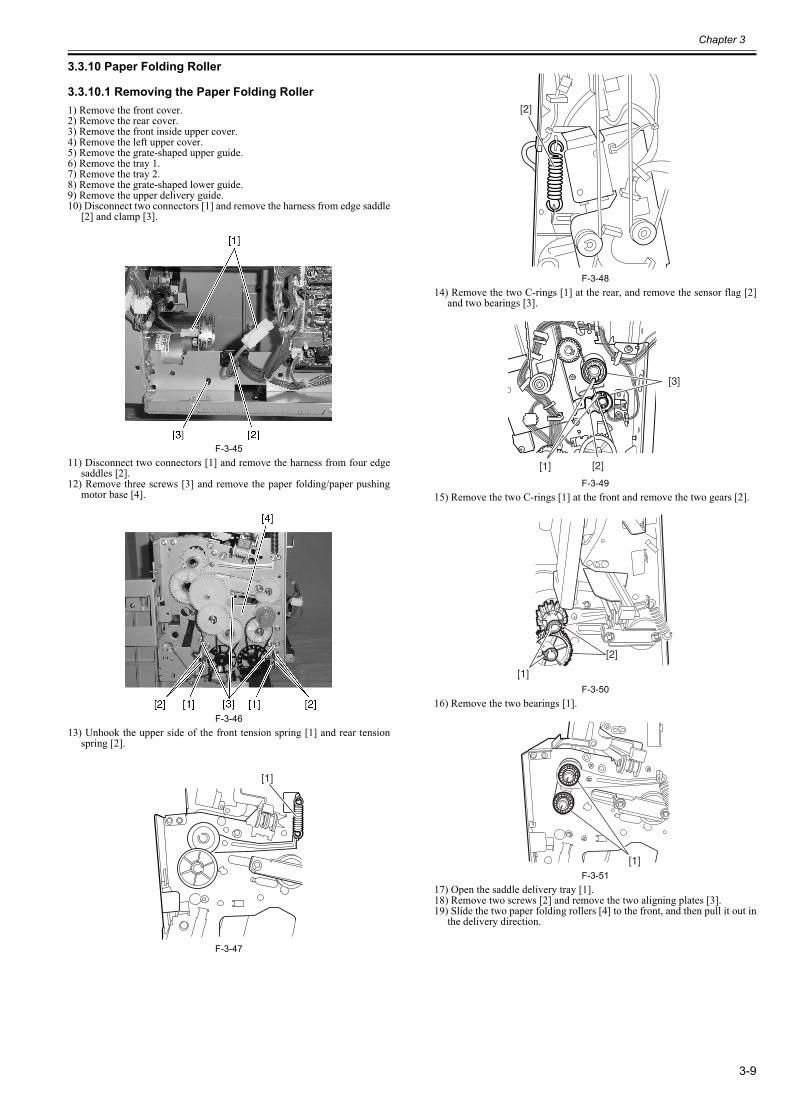
Chapter 3
3-9
3.3.10 Paper Folding Roller
3.3.10.1 Removing the Paper Folding Roller0023-6794
1) Remove the front cover.2) Remove the rear cover.3) Remove the front inside upper cover.4) Remove the left upper cover.5) Remove the grate-shaped upper guide.6) Remove the tray 1.7) Remove the tray 2.8) Remove the grate-shaped lower guide.9) Remove the upper delivery guide.10) Disconnect two connectors [1] and remove the harness from edge saddle
[2] and clamp [3].
F-3-4511) Disconnect two connectors [1] and remove the harness from four edge
saddles [2].12) Remove three screws [3] and remove the paper folding/paper pushing
motor base [4].
F-3-4613) Unhook the upper side of the front tension spring [1] and rear tension
spring [2].
F-3-47
F-3-4814) Remove the two C-rings [1] at the rear, and remove the sensor flag [2]
and two bearings [3].
F-3-4915) Remove the two C-rings [1] at the front and remove the two gears [2].
F-3-5016) Remove the two bearings [1].
F-3-5117) Open the saddle delivery tray [1].18) Remove two screws [2] and remove the two aligning plates [3].19) Slide the two paper folding rollers [4] to the front, and then pull it out in
the delivery direction.
[1]
[2]
[3]
[1] [2]
[2]
[1]
[1]
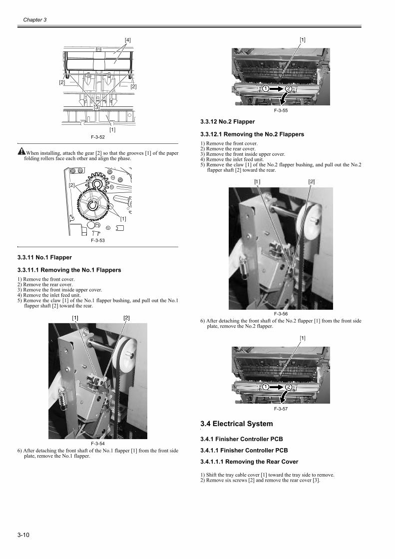
Chapter 3
3-10
F-3-52
When installing, attach the gear [2] so that the grooves [1] of the paperfolding rollers face each other and align the phase.
F-3-53
3.3.11 No.1 Flapper
3.3.11.1 Removing the No.1 Flappers0023-6800
1) Remove the front cover.2) Remove the rear cover.3) Remove the front inside upper cover.4) Remove the inlet feed unit.5) Remove the claw [1] of the No.1 flapper bushing, and pull out the No.1
flapper shaft [2] toward the rear.
F-3-546) After detaching the front shaft of the No.1 flapper [1] from the front side
plate, remove the No.1 flapper.
F-3-55
3.3.12 No.2 Flapper
3.3.12.1 Removing the No.2 Flappers0023-6805
1) Remove the front cover.2) Remove the rear cover.3) Remove the front inside upper cover.4) Remove the inlet feed unit.5) Remove the claw [1] of the No.2 flapper bushing, and pull out the No.2
flapper shaft [2] toward the rear.
F-3-566) After detaching the front shaft of the No.2 flapper [1] from the front side
plate, remove the No.2 flapper.
F-3-57
3.4 Electrical System
3.4.1 Finisher Controller PCB
3.4.1.1 Finisher Controller PCB
3.4.1.1.1 Removing the Rear Cover0023-6806
1) Shift the tray cable cover [1] toward the tray side to remove.2) Remove six screws [2] and remove the rear cover [3].
[1]
[3]
[2][2]
[4]
[1]
[2]
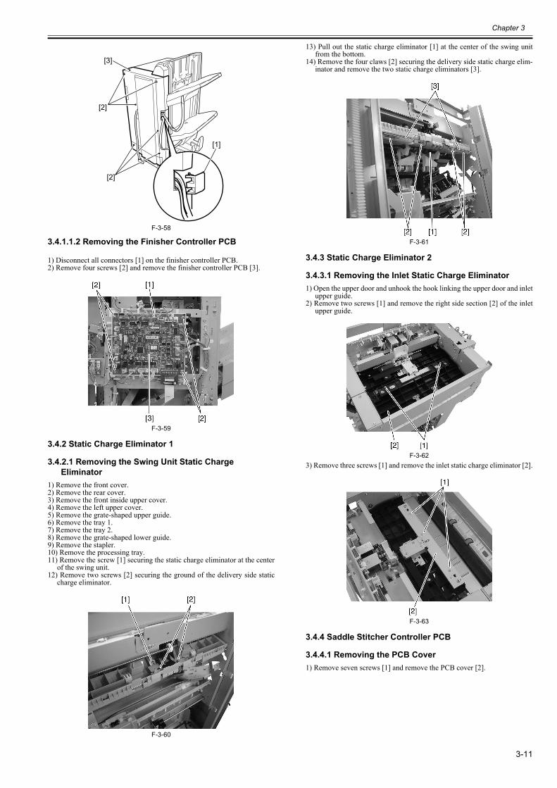
Chapter 3
3-11
F-3-58
3.4.1.1.2 Removing the Finisher Controller PCB0023-6808
1) Disconnect all connectors [1] on the finisher controller PCB.2) Remove four screws [2] and remove the finisher controller PCB [3].
F-3-59
3.4.2 Static Charge Eliminator 1
3.4.2.1 Removing the Swing Unit Static Charge Eliminator
0023-6906
1) Remove the front cover.2) Remove the rear cover.3) Remove the front inside upper cover.4) Remove the left upper cover.5) Remove the grate-shaped upper guide.6) Remove the tray 1.7) Remove the tray 2.8) Remove the grate-shaped lower guide.9) Remove the stapler.10) Remove the processing tray.11) Remove the screw [1] securing the static charge eliminator at the center
of the swing unit.12) Remove two screws [2] securing the ground of the delivery side static
charge eliminator.
F-3-60
13) Pull out the static charge eliminator [1] at the center of the swing unitfrom the bottom.
14) Remove the four claws [2] securing the delivery side static charge elim-inator and remove the two static charge eliminators [3].
F-3-61
3.4.3 Static Charge Eliminator 2
3.4.3.1 Removing the Inlet Static Charge Eliminator0023-6908
1) Open the upper door and unhook the hook linking the upper door and inletupper guide.
2) Remove two screws [1] and remove the right side section [2] of the inletupper guide.
F-3-623) Remove three screws [1] and remove the inlet static charge eliminator [2].
F-3-63
3.4.4 Saddle Stitcher Controller PCB
3.4.4.1 Removing the PCB Cover0023-6909
1) Remove seven screws [1] and remove the PCB cover [2].
[2]
[1]
[3]
[2]
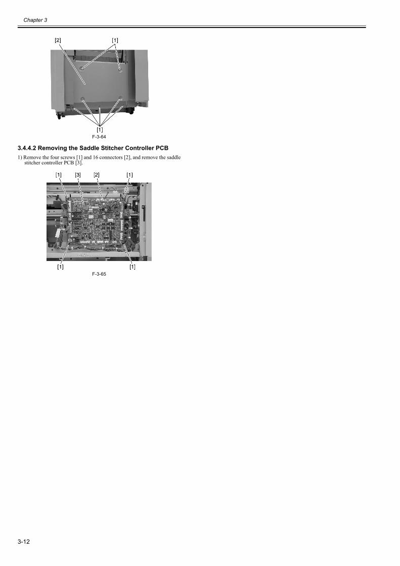
Chapter 3
3-12
F-3-64
3.4.4.2 Removing the Saddle Stitcher Controller PCB0023-6910
1) Remove the four screws [1] and 16 connectors [2], and remove the saddlestitcher controller PCB [3].
F-3-65

Chapter 4 Maintenance

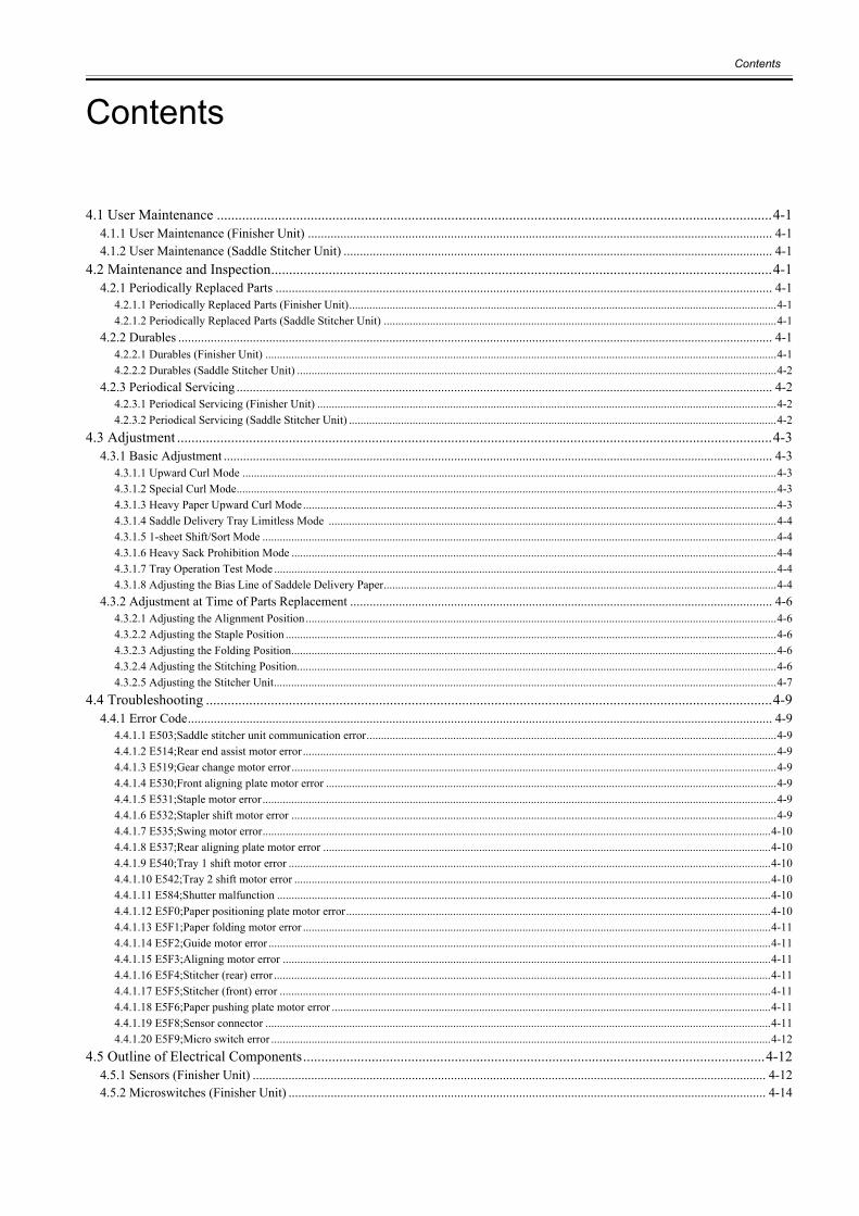
Contents
Contents
4.1 User Maintenance ..........................................................................................................................................................4-14.1.1 User Maintenance (Finisher Unit) ............................................................................................................................................... 4-14.1.2 User Maintenance (Saddle Stitcher Unit) .................................................................................................................................... 4-1
4.2 Maintenance and Inspection...........................................................................................................................................4-14.2.1 Periodically Replaced Parts ......................................................................................................................................................... 4-1
4.2.1.1 Periodically Replaced Parts (Finisher Unit)....................................................................................................................................................4-14.2.1.2 Periodically Replaced Parts (Saddle Stitcher Unit) ........................................................................................................................................4-1
4.2.2 Durables ....................................................................................................................................................................................... 4-14.2.2.1 Durables (Finisher Unit) .................................................................................................................................................................................4-14.2.2.2 Durables (Saddle Stitcher Unit) ......................................................................................................................................................................4-2
4.2.3 Periodical Servicing ..................................................................................................................................................................... 4-24.2.3.1 Periodical Servicing (Finisher Unit) ...............................................................................................................................................................4-24.2.3.2 Periodical Servicing (Saddle Stitcher Unit) ....................................................................................................................................................4-2
4.3 Adjustment .....................................................................................................................................................................4-34.3.1 Basic Adjustment ......................................................................................................................................................................... 4-3
4.3.1.1 Upward Curl Mode .........................................................................................................................................................................................4-34.3.1.2 Special Curl Mode...........................................................................................................................................................................................4-34.3.1.3 Heavy Paper Upward Curl Mode....................................................................................................................................................................4-34.3.1.4 Saddle Delivery Tray Limitless Mode ...........................................................................................................................................................4-44.3.1.5 1-sheet Shift/Sort Mode ..................................................................................................................................................................................4-44.3.1.6 Heavy Sack Prohibition Mode ........................................................................................................................................................................4-44.3.1.7 Tray Operation Test Mode ..............................................................................................................................................................................4-44.3.1.8 Adjusting the Bias Line of Saddele Delivery Paper........................................................................................................................................4-4
4.3.2 Adjustment at Time of Parts Replacement .................................................................................................................................. 4-64.3.2.1 Adjusting the Alignment Position...................................................................................................................................................................4-64.3.2.2 Adjusting the Staple Position ..........................................................................................................................................................................4-64.3.2.3 Adjusting the Folding Position........................................................................................................................................................................4-64.3.2.4 Adjusting the Stitching Position......................................................................................................................................................................4-64.3.2.5 Adjusting the Stitcher Unit..............................................................................................................................................................................4-7
4.4 Troubleshooting .............................................................................................................................................................4-94.4.1 Error Code.................................................................................................................................................................................... 4-9
4.4.1.1 E503;Saddle stitcher unit communication error..............................................................................................................................................4-94.4.1.2 E514;Rear end assist motor error ....................................................................................................................................................................4-94.4.1.3 E519;Gear change motor error........................................................................................................................................................................4-94.4.1.4 E530;Front aligning plate motor error ............................................................................................................................................................4-94.4.1.5 E531;Staple motor error ..................................................................................................................................................................................4-94.4.1.6 E532;Stapler shift motor error ........................................................................................................................................................................4-94.4.1.7 E535;Swing motor error................................................................................................................................................................................4-104.4.1.8 E537;Rear aligning plate motor error ...........................................................................................................................................................4-104.4.1.9 E540;Tray 1 shift motor error .......................................................................................................................................................................4-104.4.1.10 E542;Tray 2 shift motor error .....................................................................................................................................................................4-104.4.1.11 E584;Shutter malfunction ...........................................................................................................................................................................4-104.4.1.12 E5F0;Paper positioning plate motor error...................................................................................................................................................4-104.4.1.13 E5F1;Paper folding motor error ..................................................................................................................................................................4-114.4.1.14 E5F2;Guide motor error ..............................................................................................................................................................................4-114.4.1.15 E5F3;Aligning motor error .........................................................................................................................................................................4-114.4.1.16 E5F4;Stitcher (rear) error ............................................................................................................................................................................4-114.4.1.17 E5F5;Stitcher (front) error ..........................................................................................................................................................................4-114.4.1.18 E5F6;Paper pushing plate motor error ........................................................................................................................................................4-114.4.1.19 E5F8;Sensor connector ...............................................................................................................................................................................4-114.4.1.20 E5F9;Micro switch error .............................................................................................................................................................................4-12
4.5 Outline of Electrical Components................................................................................................................................4-124.5.1 Sensors (Finisher Unit) .............................................................................................................................................................. 4-124.5.2 Microswitches (Finisher Unit) ................................................................................................................................................... 4-14
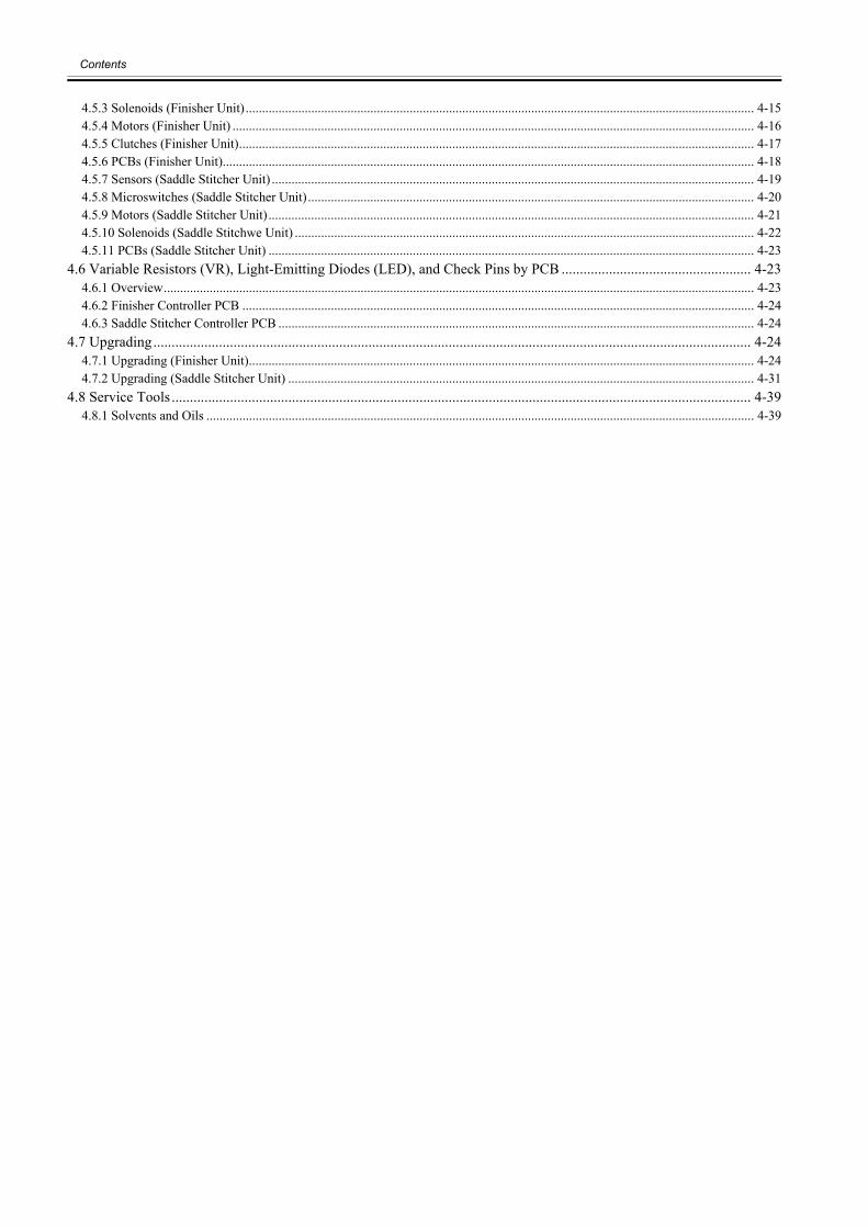
Contents
4.5.3 Solenoids (Finisher Unit)........................................................................................................................................................... 4-154.5.4 Motors (Finisher Unit) ............................................................................................................................................................... 4-164.5.5 Clutches (Finisher Unit)............................................................................................................................................................. 4-174.5.6 PCBs (Finisher Unit).................................................................................................................................................................. 4-184.5.7 Sensors (Saddle Stitcher Unit) ................................................................................................................................................... 4-194.5.8 Microswitches (Saddle Stitcher Unit)........................................................................................................................................ 4-204.5.9 Motors (Saddle Stitcher Unit).................................................................................................................................................... 4-214.5.10 Solenoids (Saddle Stitchwe Unit) ............................................................................................................................................ 4-224.5.11 PCBs (Saddle Stitcher Unit) .................................................................................................................................................... 4-23
4.6 Variable Resistors (VR), Light-Emitting Diodes (LED), and Check Pins by PCB .................................................... 4-234.6.1 Overview.................................................................................................................................................................................... 4-234.6.2 Finisher Controller PCB ............................................................................................................................................................ 4-244.6.3 Saddle Stitcher Controller PCB ................................................................................................................................................. 4-24
4.7 Upgrading.................................................................................................................................................................... 4-244.7.1 Upgrading (Finisher Unit).......................................................................................................................................................... 4-244.7.2 Upgrading (Saddle Stitcher Unit) .............................................................................................................................................. 4-31
4.8 Service Tools ............................................................................................................................................................... 4-394.8.1 Solvents and Oils ....................................................................................................................................................................... 4-39
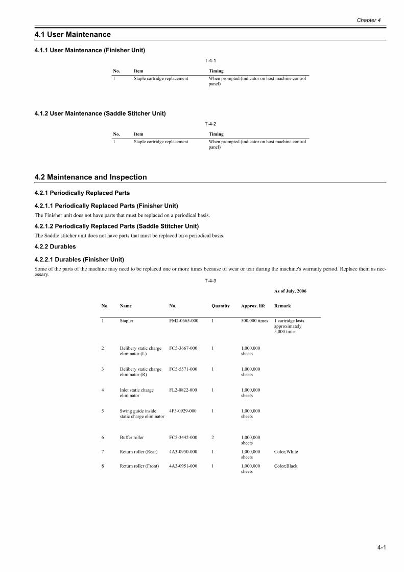
Chapter 4
4-1
4.1 User Maintenance
4.1.1 User Maintenance (Finisher Unit)0023-6911
T-4-1
4.1.2 User Maintenance (Saddle Stitcher Unit)0023-6912
T-4-2
4.2 Maintenance and Inspection
4.2.1 Periodically Replaced Parts
4.2.1.1 Periodically Replaced Parts (Finisher Unit)0023-6913
The Finisher unit does not have parts that must be replaced on a periodical basis.
4.2.1.2 Periodically Replaced Parts (Saddle Stitcher Unit)0023-6914
The Saddle stitcher unit does not have parts that must be replaced on a periodical basis.
4.2.2 Durables
4.2.2.1 Durables (Finisher Unit)0023-6915
Some of the parts of the machine may need to be replaced one or more times because of wear or tear during the machine's warranty period. Replace them as nec-essary.
T-4-3
No. Item Timing1 Staple cartridge replacement When prompted (indicator on host machine control
panel)
No. Item Timing1 Staple cartridge replacement When prompted (indicator on host machine control
panel)
As of July, 2006
No. Name No. Quantity Approx. life Remark
1 Stapler FM2-0665-000 1 500,000 times 1 cartridge lasts approximately5,000 times
2 Delibery static charge eliminator (L)
FC5-3667-000 1 1,000,000 sheets
3 Delibery static chargeeliminator (R)
FC5-5571-000 1 1,000,000 sheets
4 Inlet static chargeeliminator
FL2-0822-000 1 1,000,000 sheets
5 Swing guide insidestatic charge eliminator
4F3-0929-000 1 1,000,000 sheets
6 Buffer roller FC5-3442-000 2 1,000,000 sheets
7 Return roller (Rear) 4A3-0950-000 1 1,000,000 sheets
Color;White
8 Return roller (Front) 4A3-0951-000 1 1,000,000 sheets
Color;Black
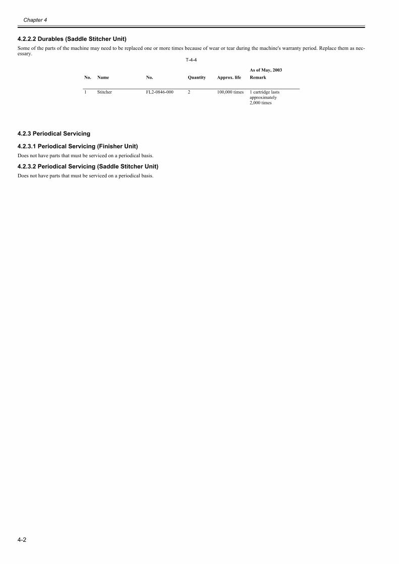
Chapter 4
4-2
4.2.2.2 Durables (Saddle Stitcher Unit)0023-6916
Some of the parts of the machine may need to be replaced one or more times because of wear or tear during the machine's warranty period. Replace them as nec-essary.
T-4-4
4.2.3 Periodical Servicing
4.2.3.1 Periodical Servicing (Finisher Unit)0023-6917
Does not have parts that must be serviced on a periodical basis.
4.2.3.2 Periodical Servicing (Saddle Stitcher Unit)0023-6918
Does not have parts that must be serviced on a periodical basis.
As of May, 2003No. Name No. Quantity Approx. life Remark
1 Stitcher FL2-0846-000 2 100,000 times 1 cartridge lasts approximately2,000 times
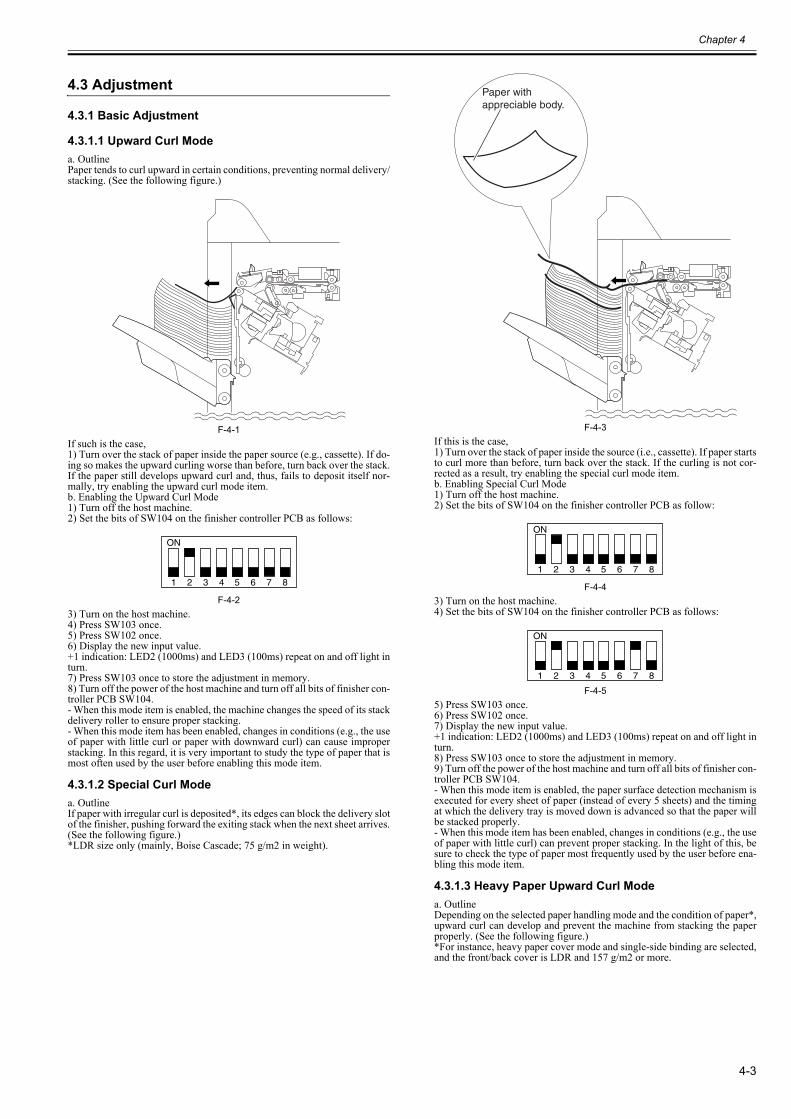
Chapter 4
4-3
4.3 Adjustment
4.3.1 Basic Adjustment
4.3.1.1 Upward Curl Mode0023-6919
a. OutlinePaper tends to curl upward in certain conditions, preventing normal delivery/stacking. (See the following figure.)
F-4-1If such is the case,1) Turn over the stack of paper inside the paper source (e.g., cassette). If do-ing so makes the upward curling worse than before, turn back over the stack.If the paper still develops upward curl and, thus, fails to deposit itself nor-mally, try enabling the upward curl mode item.b. Enabling the Upward Curl Mode1) Turn off the host machine.2) Set the bits of SW104 on the finisher controller PCB as follows:
F-4-23) Turn on the host machine.4) Press SW103 once.5) Press SW102 once.6) Display the new input value.+1 indication: LED2 (1000ms) and LED3 (100ms) repeat on and off light inturn.7) Press SW103 once to store the adjustment in memory.8) Turn off the power of the host machine and turn off all bits of finisher con-troller PCB SW104.- When this mode item is enabled, the machine changes the speed of its stackdelivery roller to ensure proper stacking.- When this mode item has been enabled, changes in conditions (e.g., the useof paper with little curl or paper with downward curl) can cause improperstacking. In this regard, it is very important to study the type of paper that ismost often used by the user before enabling this mode item.
4.3.1.2 Special Curl Mode0023-6920
a. OutlineIf paper with irregular curl is deposited*, its edges can block the delivery slotof the finisher, pushing forward the exiting stack when the next sheet arrives.(See the following figure.)*LDR size only (mainly, Boise Cascade; 75 g/m2 in weight).
F-4-3If this is the case,1) Turn over the stack of paper inside the source (i.e., cassette). If paper startsto curl more than before, turn back over the stack. If the curling is not cor-rected as a result, try enabling the special curl mode item.b. Enabling Special Curl Mode1) Turn off the host machine.2) Set the bits of SW104 on the finisher controller PCB as follow:
F-4-43) Turn on the host machine.4) Set the bits of SW104 on the finisher controller PCB as follows:
F-4-55) Press SW103 once.6) Press SW102 once.7) Display the new input value.+1 indication: LED2 (1000ms) and LED3 (100ms) repeat on and off light inturn.8) Press SW103 once to store the adjustment in memory.9) Turn off the power of the host machine and turn off all bits of finisher con-troller PCB SW104.- When this mode item is enabled, the paper surface detection mechanism isexecuted for every sheet of paper (instead of every 5 sheets) and the timingat which the delivery tray is moved down is advanced so that the paper willbe stacked properly.- When this mode item has been enabled, changes in conditions (e.g., the useof paper with little curl) can prevent proper stacking. In the light of this, besure to check the type of paper most frequently used by the user before ena-bling this mode item.
4.3.1.3 Heavy Paper Upward Curl Mode0023-6921
a. OutlineDepending on the selected paper handling mode and the condition of paper*,upward curl can develop and prevent the machine from stacking the paperproperly. (See the following figure.)*For instance, heavy paper cover mode and single-side binding are selected,and the front/back cover is LDR and 157 g/m2 or more.
ON
1 2 3 4 5 6 7 8
Paper with appreciable body.
ON
1 2 3 4 5 6 7 8
ON
1 2 3 4 5 6 7 8
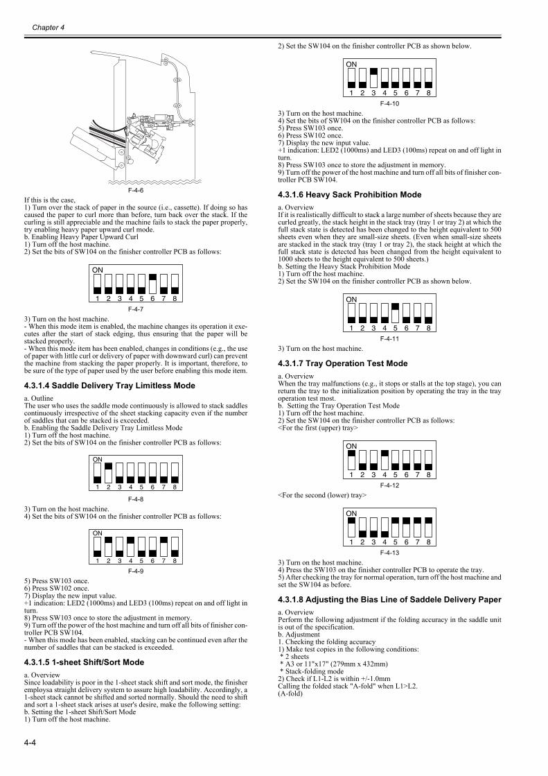
Chapter 4
4-4
F-4-6If this is the case,1) Turn over the stack of paper in the source (i.e., cassette). If doing so hascaused the paper to curl more than before, turn back over the stack. If thecurling is still appreciable and the machine fails to stack the paper properly,try enabling heavy paper upward curl mode.b. Enabling Heavy Paper Upward Curl1) Turn off the host machine.2) Set the bits of SW104 on the finisher controller PCB as follows:
F-4-73) Turn on the host machine.- When this mode item is enabled, the machine changes its operation it exe-cutes after the start of stack edging, thus ensuring that the paper will bestacked properly.- When this mode item has been enabled, changes in conditions (e.g., the useof paper with little curl or delivery of paper with downward curl) can preventthe machine from stacking the paper properly. It is important, therefore, tobe sure of the type of paper used by the user before enabling this mode item.
4.3.1.4 Saddle Delivery Tray Limitless Mode 0023-6922
a. OutlineThe user who uses the saddle mode continuously is allowed to stack saddlescontinuously irrespective of the sheet stacking capacity even if the numberof saddles that can be stacked is exceeded. b. Enabling the Saddle Delivery Tray Limitless Mode1) Turn off the host machine.2) Set the bits of SW104 on the finisher controller PCB as follows:
F-4-83) Turn on the host machine.4) Set the bits of SW104 on the finisher controller PCB as follows:
F-4-95) Press SW103 once.6) Press SW102 once.7) Display the new input value.+1 indication: LED2 (1000ms) and LED3 (100ms) repeat on and off light inturn.8) Press SW103 once to store the adjustment in memory.9) Turn off the power of the host machine and turn off all bits of finisher con-troller PCB SW104.- When this mode has been enabled, stacking can be continued even after thenumber of saddles that can be stacked is exceeded.
4.3.1.5 1-sheet Shift/Sort Mode0023-6923
a. OverviewSince loadability is poor in the 1-sheet stack shift and sort mode, the finisheremploysa straight delivery system to assure high loadability. Accordingly, a1-sheet stack cannot be shifted and sorted normally. Should the need to shiftand sort a 1-sheet stack arises at user's desire, make the following setting:b. Setting the 1-sheet Shift/Sort Mode1) Turn off the host machine.
2) Set the SW104 on the finisher controller PCB as shown below.
F-4-103) Turn on the host machine.4) Set the bits of SW104 on the finisher controller PCB as follows:5) Press SW103 once.6) Press SW102 once.7) Display the new input value.+1 indication: LED2 (1000ms) and LED3 (100ms) repeat on and off light inturn.8) Press SW103 once to store the adjustment in memory.9) Turn off the power of the host machine and turn off all bits of finisher con-troller PCB SW104.
4.3.1.6 Heavy Sack Prohibition Mode0023-6924
a. OverviewIf it is realistically difficult to stack a large number of sheets because they arecurled greatly, the stack height in the stack tray (tray 1 or tray 2) at which thefull stack state is detected has been changed to the height equivalent to 500sheets even when they are small-size sheets. (Even when small-size sheetsare stacked in the stack tray (tray 1 or tray 2), the stack height at which thefull stack state is detected has been changed from the height equivalent to1000 sheets to the height equivalent to 500 sheets.) b. Setting the Heavy Stack Prohibition Mode1) Turn off the host machine.2) Set the SW104 on the finisher controller PCB as shown below.
F-4-113) Turn on the host machine.
4.3.1.7 Tray Operation Test Mode0023-6925
a. OverviewWhen the tray malfunctions (e.g., it stops or stalls at the top stage), you canreturn the tray to the initialization position by operating the tray in the trayoperation test most.b. Setting the Tray Operation Test Mode1) Turn off the host machine.2) Set the SW104 on the finisher controller PCB as follows:<For the first (upper) tray>
F-4-12<For the second (lower) tray>
F-4-133) Turn on the host machine.4) Press the SW103 on the finisher controller PCB to operate the tray.5) After checking the tray for normal operation, turn off the host machine andset the SW104 as before.
4.3.1.8 Adjusting the Bias Line of Saddele Delivery Paper0023-6926
a. OverviewPerform the following adjustment if the folding accuracy in the saddle unitis out of the specification.b. Adjustment1. Checking the folding accuracy1) Make test copies in the following conditions: * 2 sheets * A3 or 11"x17" (279mm x 432mm) * Stack-folding mode2) Check if L1-L2 is within +/-1.0mmCalling the folded stack "A-fold" when L1>L2.(A-fold)
ON
1 2 3 4 5 6 7 8
ON
1 2 3 4 5 6 7 8
ON
1 2 3 4 5 6 7 8
ON
1 2 3 4 5 6 7 8
ON
1 2 3 4 5 6 7 8
ON
1 2 3 4 5 6 7 8
ON
1 2 3 4 5 6 7 8
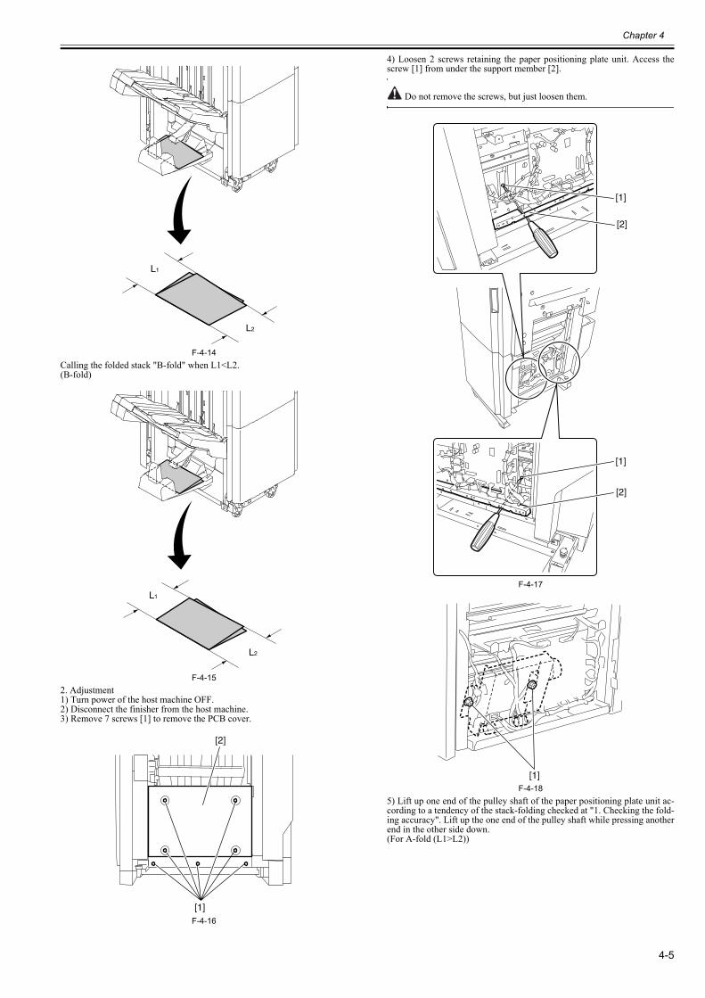
Chapter 4
4-5
F-4-14Calling the folded stack "B-fold" when L1<L2.(B-fold)
F-4-152. Adjustment1) Turn power of the host machine OFF.2) Disconnect the finisher from the host machine.3) Remove 7 screws [1] to remove the PCB cover.
F-4-16
4) Loosen 2 screws retaining the paper positioning plate unit. Access thescrew [1] from under the support member [2].
Do not remove the screws, but just loosen them.
F-4-17
F-4-185) Lift up one end of the pulley shaft of the paper positioning plate unit ac-cording to a tendency of the stack-folding checked at "1. Checking the fold-ing accuracy". Lift up the one end of the pulley shaft while pressing anotherend in the other side down.(For A-fold (L1>L2))
L1
L2
L1
L2
[2]
[1]
[1]
[1]
[2]
[2]
[1]
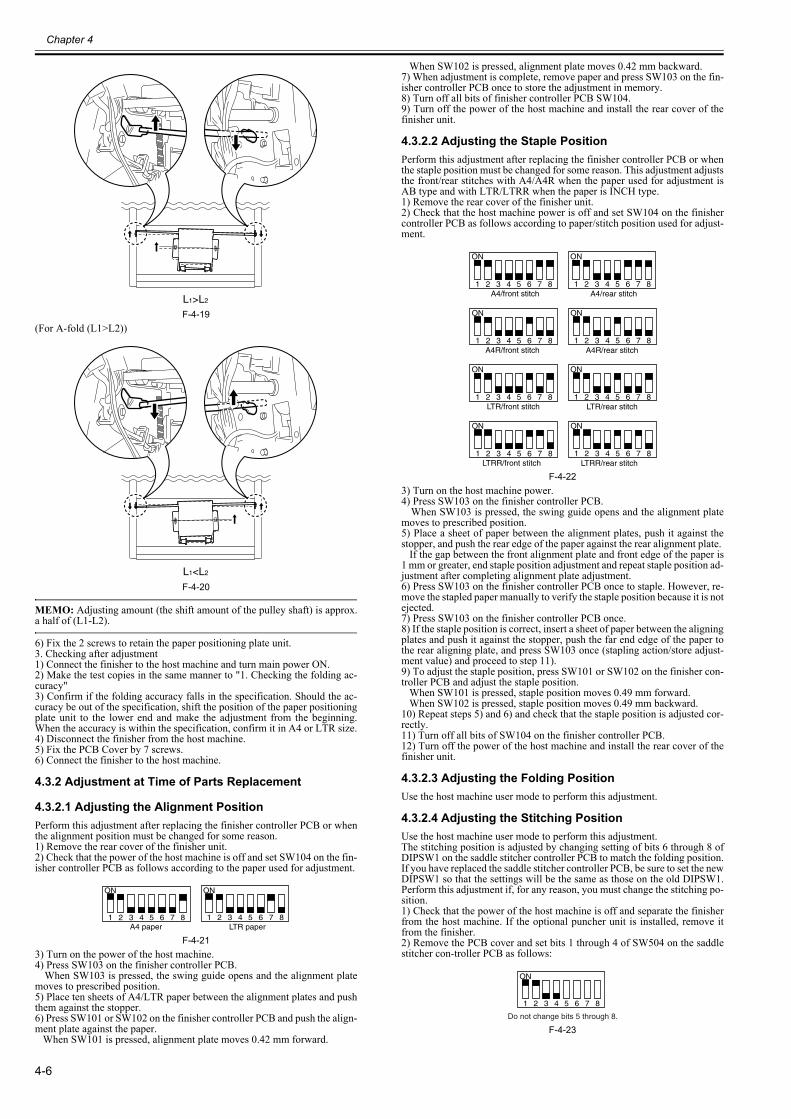
Chapter 4
4-6
F-4-19(For A-fold (L1>L2))
F-4-20
MEMO: Adjusting amount (the shift amount of the pulley shaft) is approx.a half of (L1-L2).
6) Fix the 2 screws to retain the paper positioning plate unit.3. Checking after adjustment1) Connect the finisher to the host machine and turn main power ON.2) Make the test copies in the same manner to "1. Checking the folding ac-curacy"3) Confirm if the folding accuracy falls in the specification. Should the ac-curacy be out of the specification, shift the position of the paper positioningplate unit to the lower end and make the adjustment from the beginning.When the accuracy is within the specification, confirm it in A4 or LTR size.4) Disconnect the finisher from the host machine.5) Fix the PCB Cover by 7 screws.6) Connect the finisher to the host machine.
4.3.2 Adjustment at Time of Parts Replacement
4.3.2.1 Adjusting the Alignment Position0023-6927
Perform this adjustment after replacing the finisher controller PCB or whenthe alignment position must be changed for some reason.1) Remove the rear cover of the finisher unit.2) Check that the power of the host machine is off and set SW104 on the fin-isher controller PCB as follows according to the paper used for adjustment.
F-4-213) Turn on the power of the host machine.4) Press SW103 on the finisher controller PCB. When SW103 is pressed, the swing guide opens and the alignment platemoves to prescribed position.5) Place ten sheets of A4/LTR paper between the alignment plates and pushthem against the stopper.6) Press SW101 or SW102 on the finisher controller PCB and push the align-ment plate against the paper. When SW101 is pressed, alignment plate moves 0.42 mm forward.
When SW102 is pressed, alignment plate moves 0.42 mm backward.7) When adjustment is complete, remove paper and press SW103 on the fin-isher controller PCB once to store the adjustment in memory.8) Turn off all bits of finisher controller PCB SW104.9) Turn off the power of the host machine and install the rear cover of thefinisher unit.
4.3.2.2 Adjusting the Staple Position0023-6928
Perform this adjustment after replacing the finisher controller PCB or whenthe staple position must be changed for some reason. This adjustment adjuststhe front/rear stitches with A4/A4R when the paper used for adjustment isAB type and with LTR/LTRR when the paper is INCH type.1) Remove the rear cover of the finisher unit.2) Check that the host machine power is off and set SW104 on the finishercontroller PCB as follows according to paper/stitch position used for adjust-ment.
F-4-223) Turn on the host machine power.4) Press SW103 on the finisher controller PCB. When SW103 is pressed, the swing guide opens and the alignment platemoves to prescribed position.5) Place a sheet of paper between the alignment plates, push it against thestopper, and push the rear edge of the paper against the rear alignment plate. If the gap between the front alignment plate and front edge of the paper is1 mm or greater, end staple position adjustment and repeat staple position ad-justment after completing alignment plate adjustment.6) Press SW103 on the finisher controller PCB once to staple. However, re-move the stapled paper manually to verify the staple position because it is notejected.7) Press SW103 on the finisher controller PCB once.8) If the staple position is correct, insert a sheet of paper between the aligningplates and push it against the stopper, push the far end edge of the paper tothe rear aligning plate, and press SW103 once (stapling action/store adjust-ment value) and proceed to step 11).9) To adjust the staple position, press SW101 or SW102 on the finisher con-troller PCB and adjust the staple position. When SW101 is pressed, staple position moves 0.49 mm forward. When SW102 is pressed, staple position moves 0.49 mm backward.10) Repeat steps 5) and 6) and check that the staple position is adjusted cor-rectly.11) Turn off all bits of SW104 on the finisher controller PCB.12) Turn off the power of the host machine and install the rear cover of thefinisher unit.
4.3.2.3 Adjusting the Folding Position0023-6929
Use the host machine user mode to perform this adjustment.
4.3.2.4 Adjusting the Stitching Position0023-6930
Use the host machine user mode to perform this adjustment.The stitching position is adjusted by changing setting of bits 6 through 8 ofDIPSW1 on the saddle stitcher controller PCB to match the folding position.If you have replaced the saddle stitcher controller PCB, be sure to set the newDIPSW1 so that the settings will be the same as those on the old DIPSW1.Perform this adjustment if, for any reason, you must change the stitching po-sition.1) Check that the power of the host machine is off and separate the finisherfrom the host machine. If the optional puncher unit is installed, remove itfrom the finisher.2) Remove the PCB cover and set bits 1 through 4 of SW504 on the saddlestitcher con-troller PCB as follows:
F-4-23
L1>L2
L1<L2
ON
1 2 3 4 5 6 7 8
ON
1 2 3 4 5 6 7 8LTR paperA4 paper
ON
1 2 3 4 5 6 7 8
ON
1 2 3 4 5 6 7 8A4/rear stitchA4/front stitch
ON
1 2 3 4 5 6 7 8
ON
1 2 3 4 5 6 7 8A4R/rear stitchA4R/front stitch
ON
1 2 3 4 5 6 7 8
ON
1 2 3 4 5 6 7 8 LTR/rear stitchLTR/front stitch
ON
1 2 3 4 5 6 7 8
ON
1 2 3 4 5 6 7 8LTRR/rear stitchLTRR/front stitch
ON
1 2 3 4 5 6 7 8
Do not change bits 5 through 8.
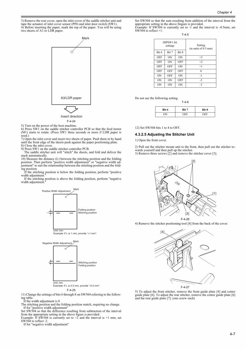
Chapter 4
4-7
3) Remove the rear cover, open the inlet cover of the saddle stitcher unit andtape the actuator of inlet cover sensor (PI9) and inlet door switch (SW1).4) Before inserting the paper, mark the top of the paper. You will be usingtwo sheets of A3 or LDR paper.
F-4-245) Turn on the power of the host machine.6) Press SW1 on the saddle stitcher controller PCB so that the feed motor(M1) starts to rotate. (Press SW1 three seconds or more if LDR paper isused.)7) Open the inlet cover and insert two sheets of paper. Push them in by handuntil the front edge of the sheets push against the paper positioning plate.8) Close the inlet cover.9) Press SW1 on the saddle stitcher controller PCB. The saddle stitcher unit will "stitch" the sheets, and fold and deliver thestack automatically.10) Measure the distance (L) between the stitching position and the foldingposition. Then perform "positive width adjustment" or "negative width ad-justment" to suit the relationship between the stitching position and the fold-ing position. If the stitching position is below the folding position, perform "positivewidth adjustment." If the stitching position is above the folding position, perform "negativewidth adjustment."
F-4-2511) Change the settings of bits 6 through 8 on SW504 referring to the follow-ing table. If the width adjustment is 0The stitching position and the folding position match, requiring no change. If for "positive width adjustment"Set SW504 so that the difference resulting from subtraction of the intervalfrom the appropriate setting in the above figure is provided.Example: If SW504 is currently set to +2 and the interval is +1 mm, setSW504 to reflect -2. If for "negative width adjustment"
Set SW504 so that the sum resulting from addition of the interval from theappropriate setting in the above fingure is provided.Example: If SW504 is currently set to -1 and the interval is -0.5mm, setSW504 to reflect +1.
T-4-5
Do not use the following setting.T-4-6
12) Set SW504 bits 1 to 4 to OFF.
4.3.2.5 Adjusting the Stitcher Unit0023-6931
1) Open the front cover.
2) Pull out the stitcher mount unit to the front, then pull out the stitcher to-wards yourself and then pull up the stitcher.3) Remove three screws [2] and remove the stitcher cover [3].
F-4-264) Remove the stitcher positioning tool [4] from the back of the cover.
F-4-275) To adjust the front stitcher, remove the front guide plate [4] and centerguide plate [6]. To adjust the rear stitcher, remove the center guide plate [6]and the rear guide plate [7]. (one screw each)
Mark
A3/LDR paper
Insert direction
Mark
Folding positionStitching position
Positive Width Adjustment
Unit: mmExample: If L is 1 mm, provide “+1 mm”.
Mark
Stitching positionFolding position
Negative Width Adjustment
Unit: mmExample: If L is 0.5 mm, provide “-0.5 mm”.
DIPSW1 bit settings Setting
(in units of 0.5 mm)Bit 6 Bit 7 Bit 8
OFF ON ON +3OFF ON OFF +2OFF OFF ON +1OFF OFF OFF 0ON OFF ON -1ON ON OFF -2ON ON ON -3
Bit 6 Bit 7 Bit 8ON OFF OFF
[2]
[3]
[1]
[4]
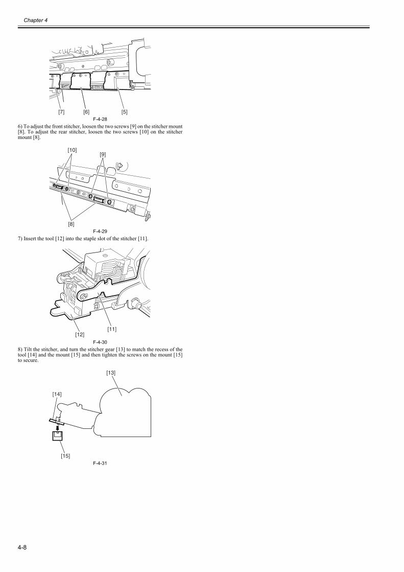
Chapter 4
4-8
F-4-286) To adjust the front stitcher, loosen the two screws [9] on the stitcher mount[8]. To adjust the rear stitcher, loosen the two screws [10] on the stitchermount [8].
F-4-297) Insert the tool [12] into the staple slot of the stitcher [11].
F-4-308) Tilt the stitcher, and turn the stitcher gear [13] to match the recess of thetool [14] and the mount [15] and then tighten the screws on the mount [15]to secure.
F-4-31
[7] [6] [5]
[10][9]
[8]
[11][12]
[15]
[14]
[13]
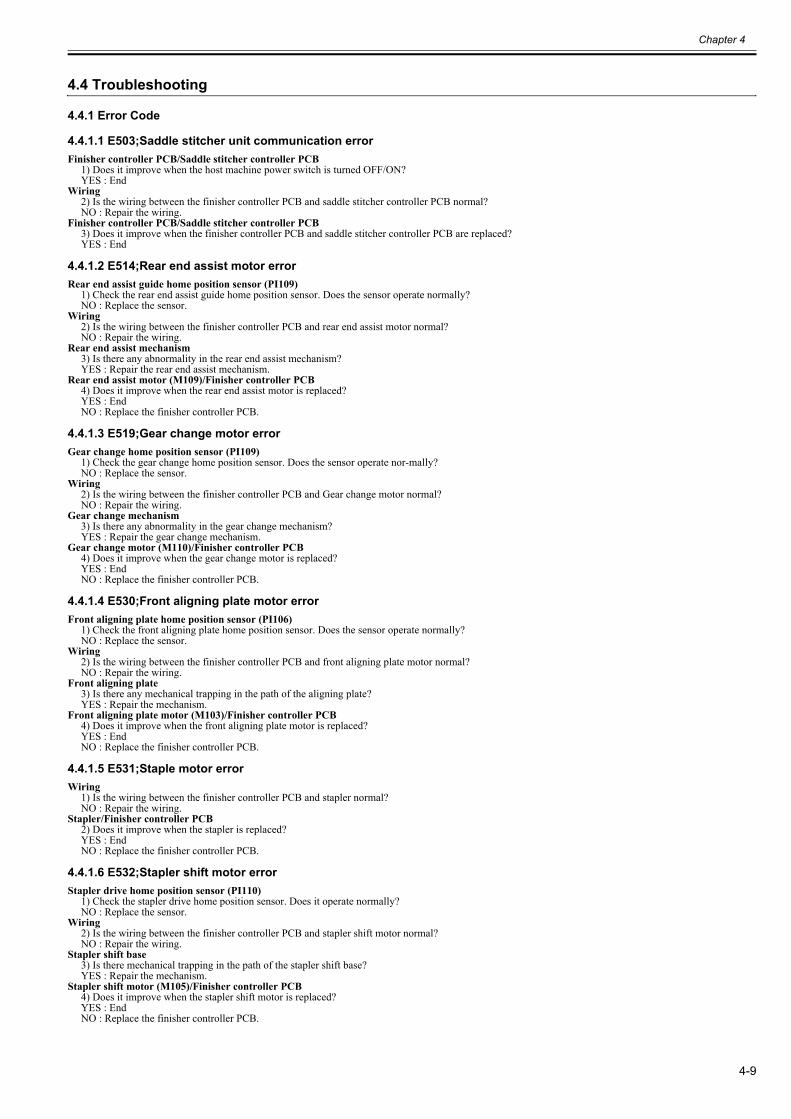
Chapter 4
4-9
4.4 Troubleshooting
4.4.1 Error Code
4.4.1.1 E503;Saddle stitcher unit communication error0023-6933
Finisher controller PCB/Saddle stitcher controller PCB1) Does it improve when the host machine power switch is turned OFF/ON?YES : End
Wiring2) Is the wiring between the finisher controller PCB and saddle stitcher controller PCB normal?NO : Repair the wiring.
Finisher controller PCB/Saddle stitcher controller PCB3) Does it improve when the finisher controller PCB and saddle stitcher controller PCB are replaced?YES : End
4.4.1.2 E514;Rear end assist motor error0023-6935
Rear end assist guide home position sensor (PI109)1) Check the rear end assist guide home position sensor. Does the sensor operate normally?NO : Replace the sensor.
Wiring2) Is the wiring between the finisher controller PCB and rear end assist motor normal?NO : Repair the wiring.
Rear end assist mechanism3) Is there any abnormality in the rear end assist mechanism?YES : Repair the rear end assist mechanism.
Rear end assist motor (M109)/Finisher controller PCB4) Does it improve when the rear end assist motor is replaced?YES : EndNO : Replace the finisher controller PCB.
4.4.1.3 E519;Gear change motor error0023-6936
Gear change home position sensor (PI109)1) Check the gear change home position sensor. Does the sensor operate nor-mally?NO : Replace the sensor.
Wiring2) Is the wiring between the finisher controller PCB and Gear change motor normal?NO : Repair the wiring.
Gear change mechanism3) Is there any abnormality in the gear change mechanism?YES : Repair the gear change mechanism.
Gear change motor (M110)/Finisher controller PCB4) Does it improve when the gear change motor is replaced?YES : EndNO : Replace the finisher controller PCB.
4.4.1.4 E530;Front aligning plate motor error0023-6937
Front aligning plate home position sensor (PI106)1) Check the front aligning plate home position sensor. Does the sensor operate normally?NO : Replace the sensor.
Wiring2) Is the wiring between the finisher controller PCB and front aligning plate motor normal?NO : Repair the wiring.
Front aligning plate3) Is there any mechanical trapping in the path of the aligning plate?YES : Repair the mechanism.
Front aligning plate motor (M103)/Finisher controller PCB4) Does it improve when the front aligning plate motor is replaced?YES : EndNO : Replace the finisher controller PCB.
4.4.1.5 E531;Staple motor error0023-6938
Wiring1) Is the wiring between the finisher controller PCB and stapler normal?NO : Repair the wiring.
Stapler/Finisher controller PCB2) Does it improve when the stapler is replaced?YES : EndNO : Replace the finisher controller PCB.
4.4.1.6 E532;Stapler shift motor error0023-6939
Stapler drive home position sensor (PI110)1) Check the stapler drive home position sensor. Does it operate normally?NO : Replace the sensor.
Wiring2) Is the wiring between the finisher controller PCB and stapler shift motor normal?NO : Repair the wiring.
Stapler shift base3) Is there mechanical trapping in the path of the stapler shift base?YES : Repair the mechanism.
Stapler shift motor (M105)/Finisher controller PCB4) Does it improve when the stapler shift motor is replaced?YES : EndNO : Replace the finisher controller PCB.
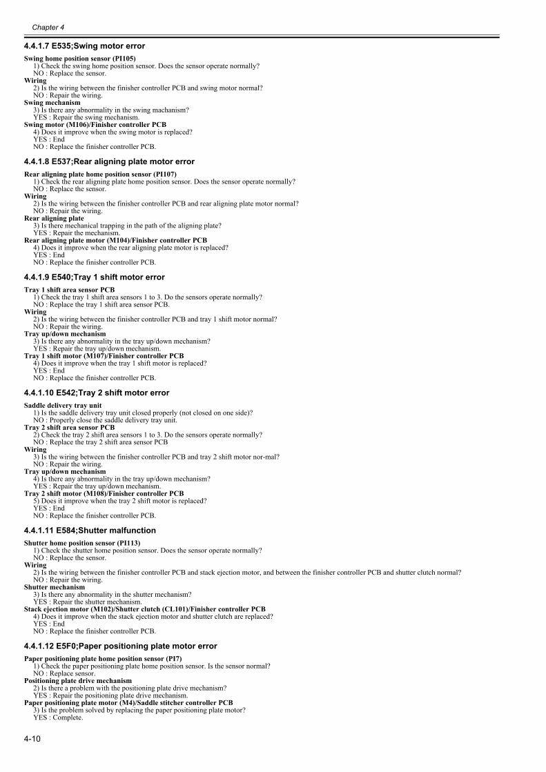
Chapter 4
4-10
4.4.1.7 E535;Swing motor error0023-6940
Swing home position sensor (PI105)1) Check the swing home position sensor. Does the sensor operate normally?NO : Replace the sensor.
Wiring2) Is the wiring between the finisher controller PCB and swing motor normal?NO : Repair the wiring.
Swing mechanism3) Is there any abnormality in the swing machanism?YES : Repair the swing mechanism.
Swing motor (M106)/Finisher controller PCB4) Does it improve when the swing motor is replaced?YES : EndNO : Replace the finisher controller PCB.
4.4.1.8 E537;Rear aligning plate motor error0023-6941
Rear aligning plate home position sensor (PI107)1) Check the rear aligning plate home position sensor. Does the sensor operate normally?NO : Replace the sensor.
Wiring2) Is the wiring between the finisher controller PCB and rear aligning plate motor normal?NO : Repair the wiring.
Rear aligning plate3) Is there mechanical trapping in the path of the aligning plate?YES : Repair the mechanism.
Rear aligning plate motor (M104)/Finisher controller PCB4) Does it improve when the rear aligning plate motor is replaced?YES : EndNO : Replace the finisher controller PCB.
4.4.1.9 E540;Tray 1 shift motor error0023-6942
Tray 1 shift area sensor PCB1) Check the tray 1 shift area sensors 1 to 3. Do the sensors operate normally?NO : Replace the tray 1 shift area sensor PCB.
Wiring2) Is the wiring between the finisher controller PCB and tray 1 shift motor normal?NO : Repair the wiring.
Tray up/down mechanism3) Is there any abnormality in the tray up/down mechanism?YES : Repair the tray up/down mechanism.
Tray 1 shift motor (M107)/Finisher controller PCB4) Does it improve when the tray 1 shift motor is replaced?YES : EndNO : Replace the finisher controller PCB.
4.4.1.10 E542;Tray 2 shift motor error0023-6944
Saddle delivery tray unit1) Is the saddle delivery tray unit closed properly (not closed on one side)?NO : Properly close the saddle delivery tray unit.
Tray 2 shift area sensor PCB2) Check the tray 2 shift area sensors 1 to 3. Do the sensors operate normally?NO : Replace the tray 2 shift area sensor PCB
Wiring3) Is the wiring between the finisher controller PCB and tray 2 shift motor nor-mal?NO : Repair the wiring.
Tray up/down mechanism4) Is there any abnormality in the tray up/down mechanism?YES : Repair the tray up/down mechanism.
Tray 2 shift motor (M108)/Finisher controller PCB5) Does it improve when the tray 2 shift motor is replaced?YES : EndNO : Replace the finisher controller PCB.
4.4.1.11 E584;Shutter malfunction0023-6945
Shutter home position sensor (PI113)1) Check the shutter home position sensor. Does the sensor operate normally?NO : Replace the sensor.
Wiring2) Is the wiring between the finisher controller PCB and stack ejection motor, and between the finisher controller PCB and shutter clutch normal?NO : Repair the wiring.
Shutter mechanism3) Is there any abnormality in the shutter mechanism?YES : Repair the shutter mechanism.
Stack ejection motor (M102)/Shutter clutch (CL101)/Finisher controller PCB4) Does it improve when the stack ejection motor and shutter clutch are replaced?YES : EndNO : Replace the finisher controller PCB.
4.4.1.12 E5F0;Paper positioning plate motor error0023-6946
Paper positioning plate home position sensor (PI7)1) Check the paper positioning plate home position sensor. Is the sensor normal?NO : Replace sensor.
Positioning plate drive mechanism2) Is there a problem with the positioning plate drive mechanism?YES : Repair the positioning plate drive mechanism.
Paper positioning plate motor (M4)/Saddle stitcher controller PCB3) Is the problem solved by replacing the paper positioning plate motor?YES : Complete.
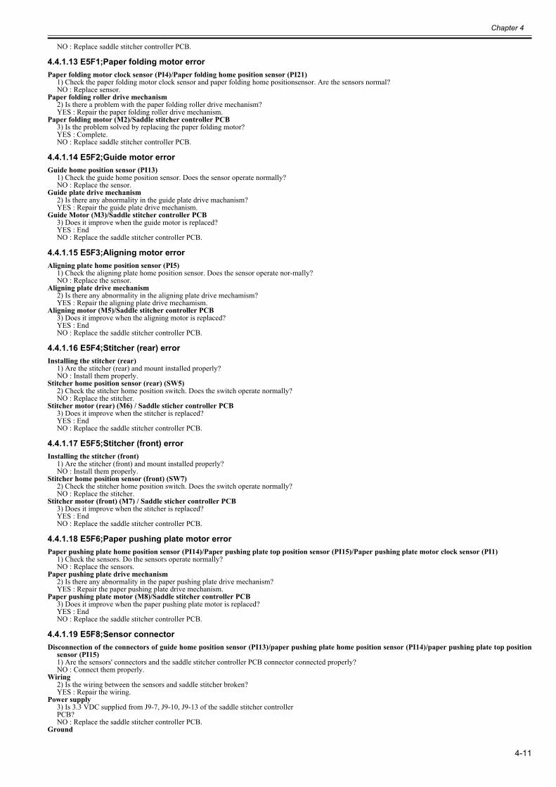
Chapter 4
4-11
NO : Replace saddle stitcher controller PCB.
4.4.1.13 E5F1;Paper folding motor error0023-6947
Paper folding motor clock sensor (PI4)/Paper folding home position sensor (PI21)1) Check the paper folding motor clock sensor and paper folding home positionsensor. Are the sensors normal?NO : Replace sensor.
Paper folding roller drive mechanism2) Is there a problem with the paper folding roller drive mechanism?YES : Repair the paper folding roller drive mechanism.
Paper folding motor (M2)/Saddle stitcher controller PCB3) Is the problem solved by replacing the paper folding motor?YES : Complete.NO : Replace saddle stitcher controller PCB.
4.4.1.14 E5F2;Guide motor error0023-6948
Guide home position sensor (PI13)1) Check the guide home position sensor. Does the sensor operate normally?NO : Replace the sensor.
Guide plate drive mechanism2) Is there any abnormality in the guide plate drive machanism?YES : Repair the guide plate drive mechanism.
Guide Motor (M3)/Saddle stitcher controller PCB3) Does it improve when the guide motor is replaced?YES : EndNO : Replace the saddle stitcher controller PCB.
4.4.1.15 E5F3;Aligning motor error0023-6949
Aligning plate home position sensor (PI5)1) Check the aligning plate home position sensor. Does the sensor operate nor-mally?NO : Replace the sensor.
Aligning plate drive mechanism2) Is there any abnormality in the aligning plate drive mechamism?YES : Repair the aligning plate drive mechamism.
Aligning motor (M5)/Saddle stitcher controller PCB3) Does it improve when the aligning motor is replaced?YES : EndNO : Replace the saddle stitcher controller PCB.
4.4.1.16 E5F4;Stitcher (rear) error0023-6950
Installing the stitcher (rear)1) Are the stitcher (rear) and mount installed properly?NO : Install them properly.
Stitcher home position sensor (rear) (SW5)2) Check the stitcher home position switch. Does the switch operate normally?NO : Replace the stitcher.
Stitcher motor (rear) (M6) / Saddle sticher controller PCB3) Does it improve when the stitcher is replaced?YES : EndNO : Replace the saddle stitcher controller PCB.
4.4.1.17 E5F5;Stitcher (front) error0023-6951
Installing the stitcher (front)1) Are the stitcher (front) and mount installed properly?NO : Install them properly.
Stitcher home position sensor (front) (SW7)2) Check the stitcher home position switch. Does the switch operate normally?NO : Replace the stitcher.
Stitcher motor (front) (M7) / Saddle sticher controller PCB3) Does it improve when the stitcher is replaced?YES : EndNO : Replace the saddle stitcher controller PCB.
4.4.1.18 E5F6;Paper pushing plate motor error0023-6952
Paper pushing plate home position sensor (PI14)/Paper pushing plate top position sensor (PI15)/Paper pushing plate motor clock sensor (PI1)1) Check the sensors. Do the sensors operate normally?NO : Replace the sensors.
Paper pushing plate drive mechanism2) Is there any abnormality in the paper pushing plate drive mechanism?YES : Repair the paper pushing plate drive mechanism.
Paper pushing plate motor (M8)/Saddle stitcher controller PCB3) Does it improve when the paper pushing plate motor is replaced?YES : EndNO : Replace the saddle stitcher controller PCB.
4.4.1.19 E5F8;Sensor connector0023-6953
Disconnection of the connectors of guide home position sensor (PI13)/paper pushing plate home position sensor (PI14)/paper pushing plate top positionsensor (PI15)1) Are the sensors' connectors and the saddle stitcher controller PCB connector connected properly?NO : Connect them properly.
Wiring2) Is the wiring between the sensors and saddle stitcher broken?YES : Repair the wiring.
Power supply3) Is 3.3 VDC supplied from J9-7, J9-10, J9-13 of the saddle stitcher controllerPCB?NO : Replace the saddle stitcher controller PCB.
Ground
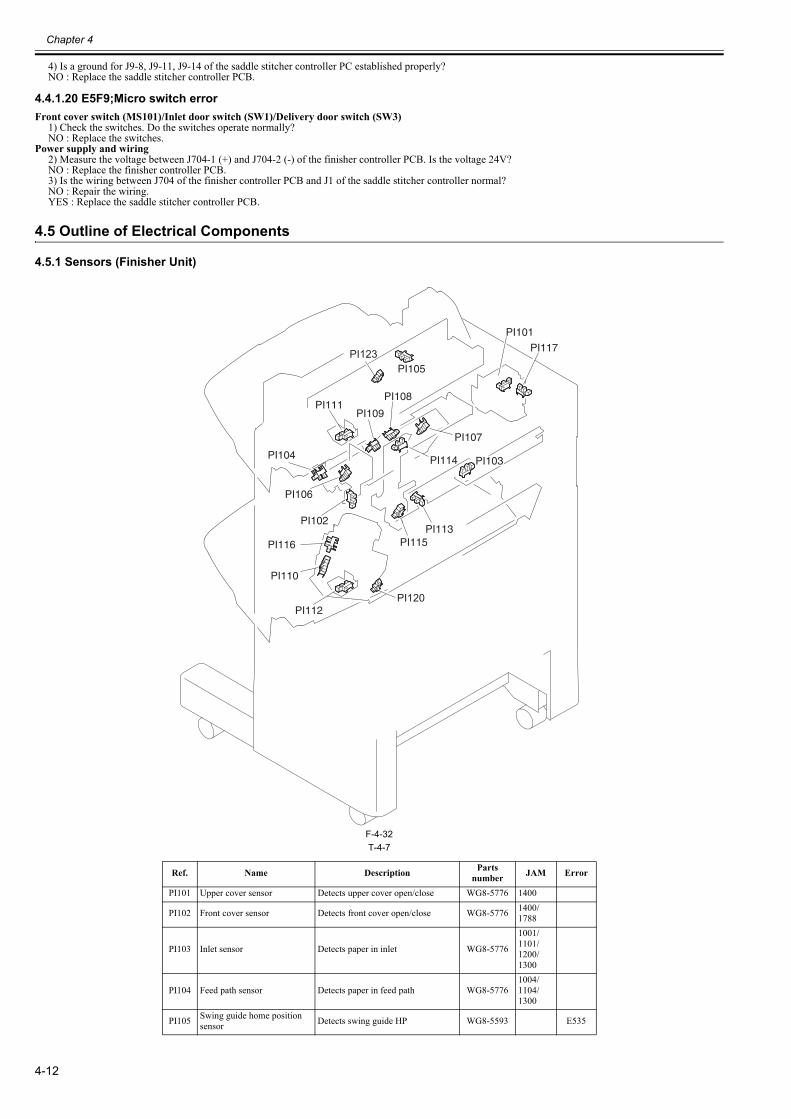
Chapter 4
4-12
4) Is a ground for J9-8, J9-11, J9-14 of the saddle stitcher controller PC established properly?NO : Replace the saddle stitcher controller PCB.
4.4.1.20 E5F9;Micro switch error0023-6954
Front cover switch (MS101)/Inlet door switch (SW1)/Delivery door switch (SW3)1) Check the switches. Do the switches operate normally?NO : Replace the switches.
Power supply and wiring2) Measure the voltage between J704-1 (+) and J704-2 (-) of the finisher controller PCB. Is the voltage 24V?NO : Replace the finisher controller PCB.3) Is the wiring between J704 of the finisher controller PCB and J1 of the saddle stitcher controller normal?NO : Repair the wiring.YES : Replace the saddle stitcher controller PCB.
4.5 Outline of Electrical Components
4.5.1 Sensors (Finisher Unit)0023-6955
F-4-32T-4-7
Ref. Name Description Parts number JAM Error
PI101 Upper cover sensor Detects upper cover open/close WG8-5776 1400
PI102 Front cover sensor Detects front cover open/close WG8-5776 1400/1788
PI103 Inlet sensor Detects paper in inlet WG8-5776
1001/1101/1200/1300
PI104 Feed path sensor Detects paper in feed path WG8-57761004/1104/1300
PI105 Swing guide home position sensor Detects swing guide HP WG8-5593 E535
PI105
PI103
PI109
PI106
PI104
PI108
PI117
PI101
PI115PI113
PI111
PI114
PI112
PI107
PI110
PI116
PI102
PI120
PI123
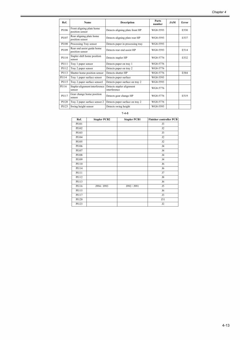
Chapter 4
4-13
T-4-8
PI106 Front aligning plate home position sensor Detects aligning plate front HP WG8-5593 E530
PI107 Rear aligning plate home position sensor Detects aligning plate rear HP WG8-5593 E537
PI108 Processing Tray sensor Detects paper in processing tray WG8-5593
PI109 Rear end assist guide home position sensor Detects rear end assist HP WG8-5593 E514
PI110 Stapler shift home position sensor Detects stapler HP WG8-5776 E532
PI111 Tray 1 paper sensor Detects paper on tray 1 WG8-5776PI112 Tray 2 paper sensor Detects paper on tray 2 WG8-5776PI113 Shutter home position sensor Detects shutter HP WG8-5776 E584
PI114 Tray 1 paper surface sensor Detects paper surface WG8-5593PI115 Tray 2 paper surface sensor1 Detects paper surface on tray 2 WG8-5593
PI116 Stapler alignment interference sensor
Detects stapler alignment interference WG8-5776
PI117 Gear change home position sensor Detects gear change HP WG8-5776 E519
PI120 Tray 2 paper surface sensor 2 Detects paper surface on tray 2 WG8-5776PI123 Swing height sensor Detects swing height WG8-5593
Ref. Stapler PCB2 Stapler PCB1 Finisher controller PCBPI101 J3PI102 J2PI103 J3PI104 J2PI105 J2PI106 J4PI107 J4PI108 J4PI109 J4PI110 J6PI114 J6PI111 J7PI112 J8PI113 J6PI116 J994 / J993 J992 / J991 J5PI115 J6PI117 J3PI120 J31PI123 J2
Ref. Name Description Parts number JAM Error
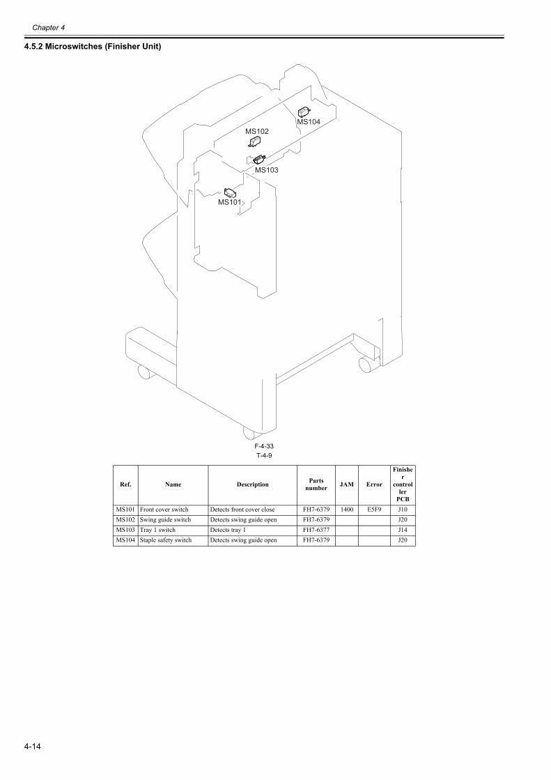
Chapter 4
4-14
4.5.2 Microswitches (Finisher Unit)0023-6956
F-4-33T-4-9
Ref. Name Description Parts number JAM Error
Finisher
controller
PCBMS101 Front cover switch Detects front cover close FH7-6379 1400 E5F9 J10MS102 Swing guide switch Detects swing guide open FH7-6379 J20MS103 Tray 1 switch Detects tray 1 FH7-6377 J14MS104 Staple safety switch Detects swing guide open FH7-6379 J20
MS103
MS101
MS103
MS101
MS102MS104
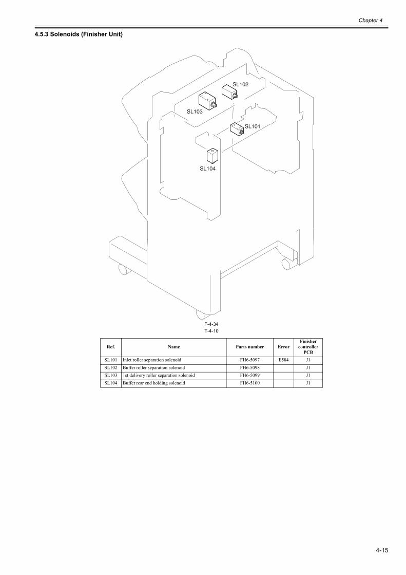
Chapter 4
4-15
4.5.3 Solenoids (Finisher Unit)0023-6957
F-4-34T-4-10
Ref. Name Parts number ErrorFinisher
controller PCB
SL101 Inlet roller separation solenoid FH6-5097 E584 J1SL102 Buffer roller separation solenoid FH6-5098 J1SL103 1st delivery roller separation solenoid FH6-5099 J1SL104 Buffer rear end holding solenoid FH6-5100 J1
SL101
SL102
SL103
SL104
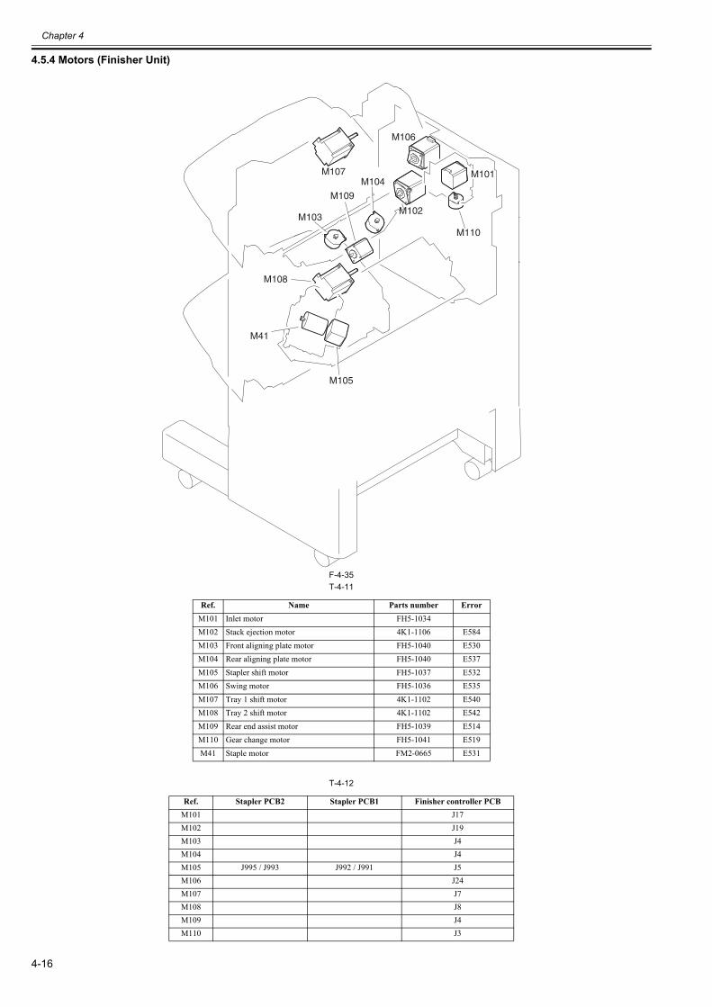
Chapter 4
4-16
4.5.4 Motors (Finisher Unit)0023-6959
F-4-35T-4-11
T-4-12
Ref. Name Parts number ErrorM101 Inlet motor FH5-1034M102 Stack ejection motor 4K1-1106 E584M103 Front aligning plate motor FH5-1040 E530M104 Rear aligning plate motor FH5-1040 E537M105 Stapler shift motor FH5-1037 E532M106 Swing motor FH5-1036 E535M107 Tray 1 shift motor 4K1-1102 E540M108 Tray 2 shift motor 4K1-1102 E542M109 Rear end assist motor FH5-1039 E514M110 Gear change motor FH5-1041 E519M41 Staple motor FM2-0665 E531
Ref. Stapler PCB2 Stapler PCB1 Finisher controller PCBM101 J17M102 J19M103 J4M104 J4M105 J995 / J993 J992 / J991 J5M106 J24M107 J7M108 J8M109 J4M110 J3
M101M107
M106
M102M102
M109
M105
M108
M41
M104
M103
M110
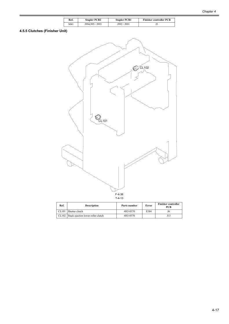
Chapter 4
4-17
4.5.5 Clutches (Finisher Unit)0023-6960
F-4-36T-4-13
M41 J994,995 / J993 J992 / J991 J5
Ref. Description Parts number Error Finisher controller PCB
CL101 Shutter clutch 4H3-0370 E584 J6CL102 Stack ejection lower roller clutch 4H3-0370 J13
Ref. Stapler PCB2 Stapler PCB1 Finisher controller PCB
CL101
CL102
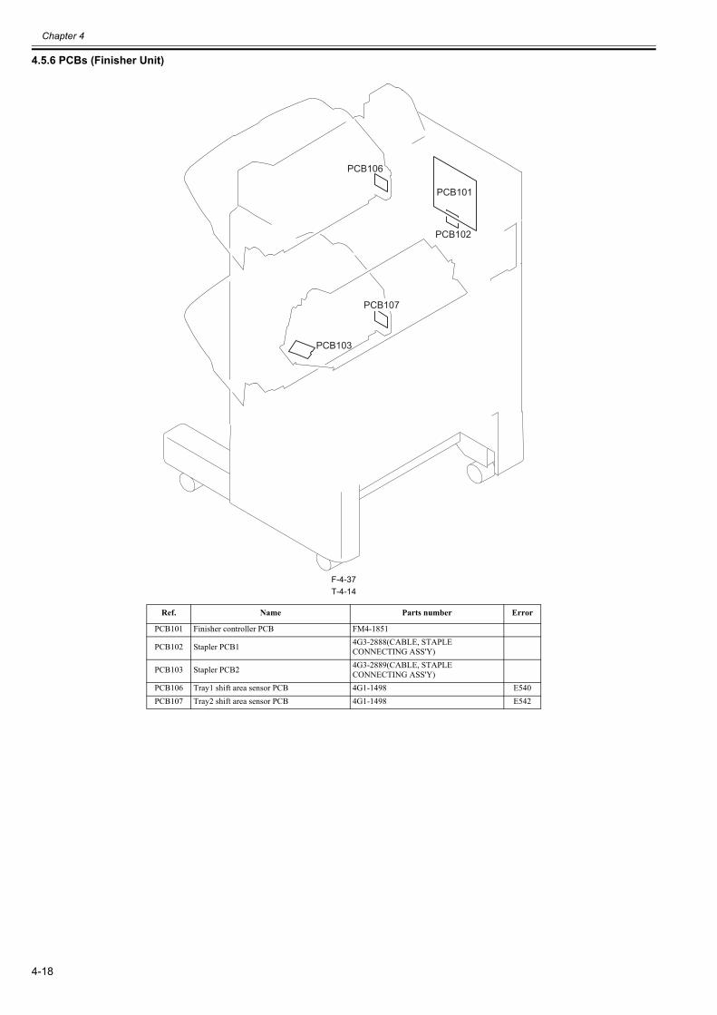
Chapter 4
4-18
4.5.6 PCBs (Finisher Unit)0023-6961
F-4-37T-4-14
Ref. Name Parts number Error
PCB101 Finisher controller PCB FM4-1851
PCB102 Stapler PCB1 4G3-2888(CABLE, STAPLE CONNECTING ASS'Y)
PCB103 Stapler PCB2 4G3-2889(CABLE, STAPLE CONNECTING ASS'Y)
PCB106 Tray1 shift area sensor PCB 4G1-1498 E540PCB107 Tray2 shift area sensor PCB 4G1-1498 E542
PCB101
PCB102
PCB103
PCB107
PCB106
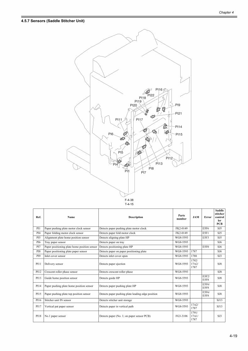
Chapter 4
4-19
4.5.7 Sensors (Saddle Stitcher Unit)0023-6962
F-4-38T-4-15
Ref. Name Description Parts number JAM Error
Saddle stitcher control
ler PCB
PI1 Paper pushing plate motor clock sensor Detects paper pushing plate motor clock FK2-0149 E5F6 SJ5PI4 Paper folding motor clock sensor Detects paper fold motor clock FK2-0149 E5F1 SJ5PI5 Alignment plate home position sensor Detects aligning plate HP WG8-5593 E5F3 SJ5PI6 Tray paper sensor Detects paper on tray WG8-5593 SJ6PI7 Paper positioning plate home position sensor Detects positioning plate HP WG8-5593 E5F0 SJ6PI8 Paper positioning plate paper sensor Detects paper on paper positioning plate WG8-5593 1787 SJ6PI9 Inlet cover sensor Detects inlet cover open WG8-5593 1788 SJ3
PI11 Delivery sensor Detects paper ejection WG8-55931792/17A2/1787
SJ8
PI12 Crescent roller phase sensor Detects crescent roller phase WG8-5593 SJ8
PI13 Guide home position sensor Detects guide HP WG8-5593 E5F2/E5F8 SJ8
PI14 Paper pushing plate home position sensor Detects paper pushing plate HP WG8-5593 E5F6/E5F8 SJ8
PI15 Paper pushing plate top position sensor Detects paper pushing plate leading edge position WG8-5593 E5F6/E5F8 SJ8
PI16 Stitcher unit IN sensor Detects stitcher unit storage WG8-5593 SJ13
PI17 Vertical pat paper sensor Detects paper in vertical path WG8-5593 17A2/1787 SJ13
PI18 No.1 paper sensor Detects paper (No. 1; on paper sensor PCB) FG3-31061791/17A1/1787
SJ3
PI4
PI18PI22
PI19PI20
PI1
PI11
PI9
PI21
PI8PI7
PI6
PI13
PI5
PI14
PI15
PI16
PI17
PI12
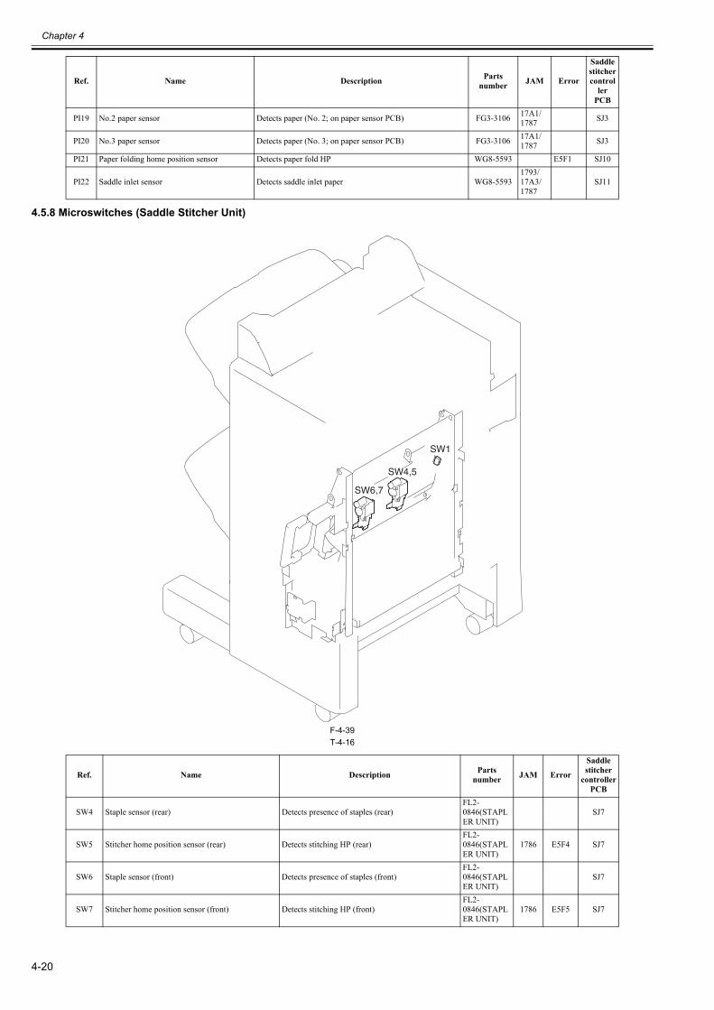
Chapter 4
4-20
4.5.8 Microswitches (Saddle Stitcher Unit)0023-6963
F-4-39T-4-16
PI19 No.2 paper sensor Detects paper (No. 2; on paper sensor PCB) FG3-3106 17A1/1787 SJ3
PI20 No.3 paper sensor Detects paper (No. 3; on paper sensor PCB) FG3-3106 17A1/1787 SJ3
PI21 Paper folding home position sensor Detects paper fold HP WG8-5593 E5F1 SJ10
PI22 Saddle inlet sensor Detects saddle inlet paper WG8-55931793/17A3/1787
SJ11
Ref. Name Description Parts number JAM Error
Saddle stitcher
controller PCB
SW4 Staple sensor (rear) Detects presence of staples (rear)FL2-0846(STAPLER UNIT)
SJ7
SW5 Stitcher home position sensor (rear) Detects stitching HP (rear)FL2-0846(STAPLER UNIT)
1786 E5F4 SJ7
SW6 Staple sensor (front) Detects presence of staples (front)FL2-0846(STAPLER UNIT)
SJ7
SW7 Stitcher home position sensor (front) Detects stitching HP (front)FL2-0846(STAPLER UNIT)
1786 E5F5 SJ7
Ref. Name Description Parts number JAM Error
Saddle stitcher control
ler PCB
SW1
SW4,5
SW6,7
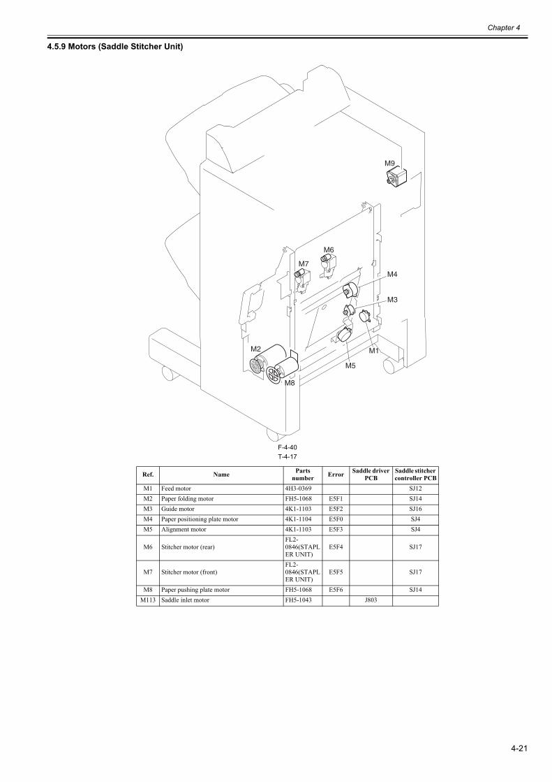
Chapter 4
4-21
4.5.9 Motors (Saddle Stitcher Unit)0023-6964
F-4-40T-4-17
Ref. Name Parts number Error Saddle driver
PCBSaddle stitcher controller PCB
M1 Feed motor 4H3-0369 SJ12M2 Paper folding motor FH5-1068 E5F1 SJ14M3 Guide motor 4K1-1103 E5F2 SJ16M4 Paper positioning plate motor 4K1-1104 E5F0 SJ4M5 Alignment motor 4K1-1103 E5F3 SJ4
M6 Stitcher motor (rear)FL2-0846(STAPLER UNIT)
E5F4 SJ17
M7 Stitcher motor (front)FL2-0846(STAPLER UNIT)
E5F5 SJ17
M8 Paper pushing plate motor FH5-1068 E5F6 SJ14M113 Saddle inlet motor FH5-1043 J803
M7
M8
M2
M6
M9
M1
M4
M5
M3
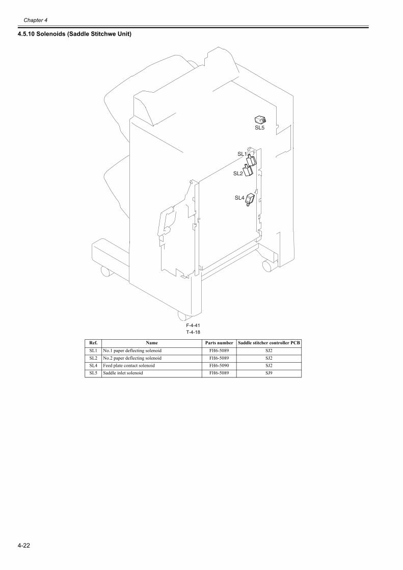
Chapter 4
4-22
4.5.10 Solenoids (Saddle Stitchwe Unit)0023-6965
F-4-41T-4-18
Ref. Name Parts number Saddle stitcher controller PCB
SL1 No.1 paper deflecting solenoid FH6-5089 SJ2SL2 No.2 paper deflecting solenoid FH6-5089 SJ2SL4 Feed plate contact solenoid FH6-5090 SJ2SL5 Saddle inlet solenoid FH6-5089 SJ9
SL1
SL2
SL5
SL4
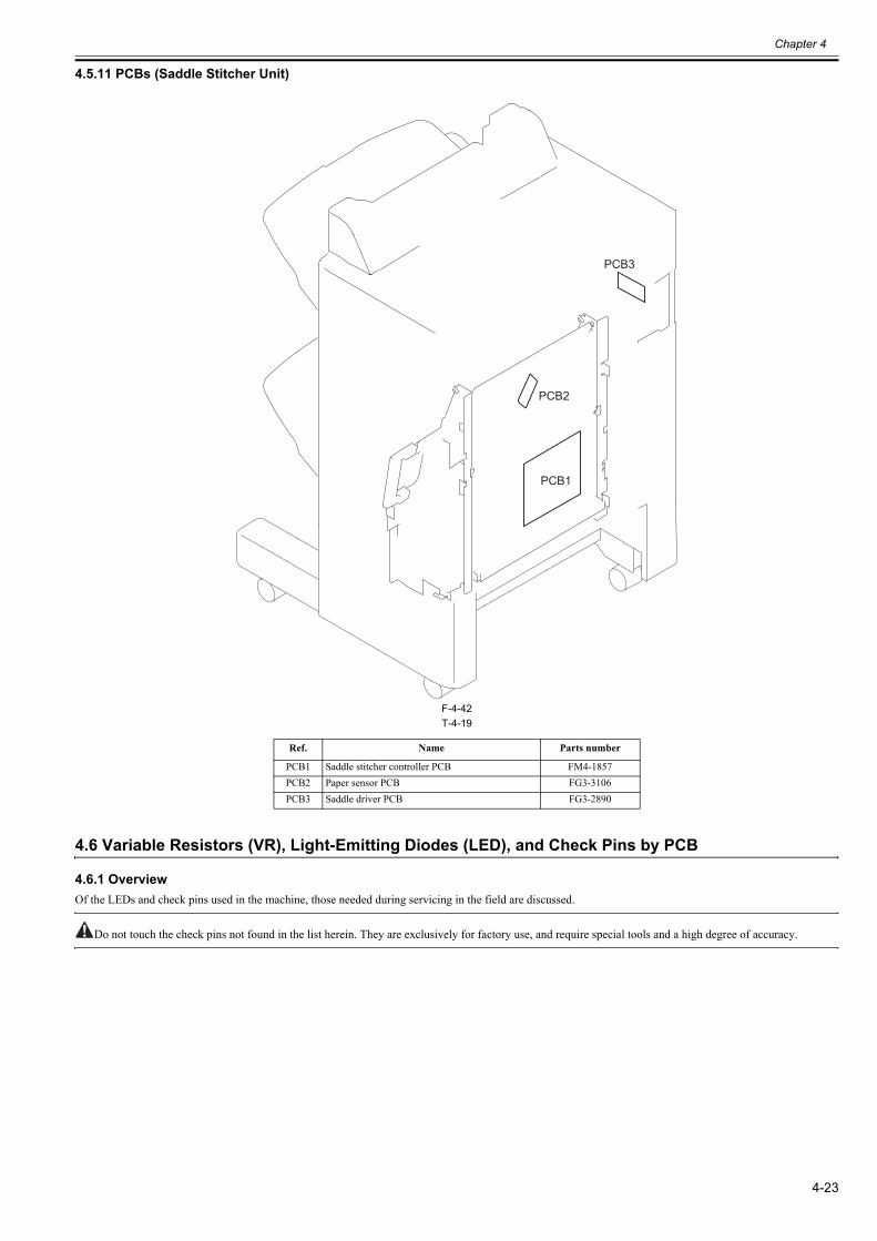
Chapter 4
4-23
4.5.11 PCBs (Saddle Stitcher Unit)0023-6966
F-4-42T-4-19
4.6 Variable Resistors (VR), Light-Emitting Diodes (LED), and Check Pins by PCB
4.6.1 Overview0023-6968
Of the LEDs and check pins used in the machine, those needed during servicing in the field are discussed.
Do not touch the check pins not found in the list herein. They are exclusively for factory use, and require special tools and a high degree of accuracy.
Ref. Name Parts number
PCB1 Saddle stitcher controller PCB FM4-1857PCB2 Paper sensor PCB FG3-3106PCB3 Saddle driver PCB FG3-2890
PCB1
PCB2
PCB3
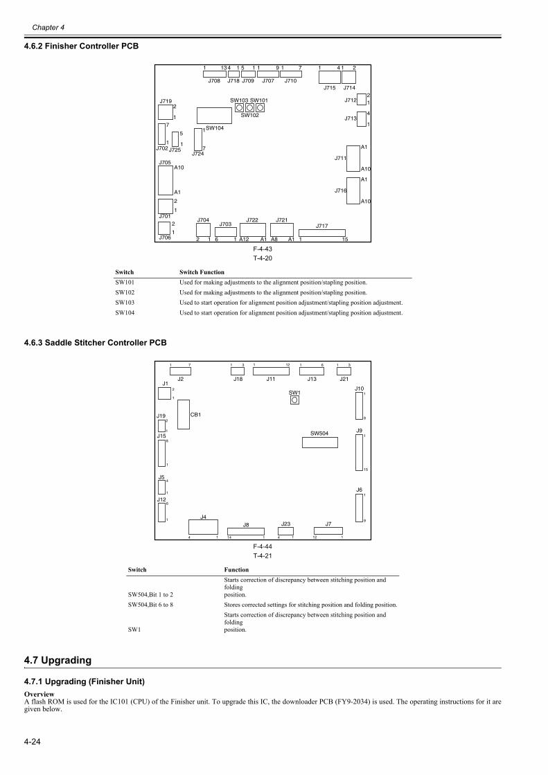
Chapter 4
4-24
4.6.2 Finisher Controller PCB0023-6969
F-4-43T-4-20
4.6.3 Saddle Stitcher Controller PCB0023-6970
F-4-44T-4-21
4.7 Upgrading
4.7.1 Upgrading (Finisher Unit)0023-6971
OverviewA flash ROM is used for the IC101 (CPU) of the Finisher unit. To upgrade this IC, the downloader PCB (FY9-2034) is used. The operating instructions for it aregiven below.
Switch Switch FunctionSW101 Used for making adjustments to the alignment position/stapling position.SW102 Used for making adjustments to the alignment position/stapling position.SW103 Used to start operation for alignment position adjustment/stapling position adjustment.SW104 Used to start operation for alignment position adjustment/stapling position adjustment.
Switch Function
SW504,Bit 1 to 2
Starts correction of discrepancy between stitching position and foldingposition.
SW504,Bit 6 to 8 Stores corrected settings for stitching position and folding position.
SW1
Starts correction of discrepancy between stitching position and foldingposition.
1 13
J708
4 1 5 1 1 9 1 7 1 4 1 2
J718 J709 J707 J710J715 J714
21J712
4
1J713
A1
A10
J711
A1
12 1
2
1
2
1
A10
2
1
1
7
7
1
A1
6 1 A12 A1 A8 A1 15
A10
J716
J717J721J722J704
SW104
J719
J702
J705
J701
J706
J724
SW103 SW101
SW102
J703
J7251
5
1 7 1 3
J2 J21
1 61 3
J13J18
6
2
1
4
121
1 14 1
1
J12
SW504
J11
1
8
J10
1
9
J6
1
15
J9
12 1
J7J4
CB1
J1
SW1
J8
2
1
J19
4
1
J5
8
1
J15
J23
4 1
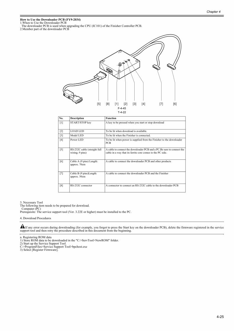
Chapter 4
4-25
How to Use the Downloader PCB (FY9-2034)1.When to Use the Downloader PCB The downloader PCB is used when upgrading the CPU (IC101) of the Finisher Controller PCB.2.Member part of the downloader PCB
F-4-45T-4-22
3. Necessary ToolThe following item needs to be prepared for download. Computer (PC)Prerequisite: The service support tool (Ver. 3.22E or higher) must be installed to the PC.
4. Download Procedures
If any error occurs during downloading (for example, you forgot to press the Start key on the downloader PCB), delete the firmware registered in the servicesupport tool and then retry the procedure described in this document from the beginning.
a. Registering ROM data1) Store ROM data to be downloaded in the "C:>ServTool>NewROM" folder.2) Start up the Service Support Tool.C:>ProgramFiles>Service Support Tool>bpchost.exe3) Select [Register Firmware].
No. Description Function [1] START/STOP key A key to be pressed when you start or stop download
[2] LOAD LED To be lit when download is available. [3] Model LED To be lit when the Finisher is connected. [4] Power LED To be lit when power is supplied from the Finisher to the downloader
PCB
[5] RS-232C cable (straight full wiring; 9 pins)
A cable to connect the downloader PCB and a PC.Be sure to connect the cable in a way that its ferrite core comes to the PC side.
[6] Cable A (9 pins) Length: approx. 70cm
A cable to connect the downloader PCB and other products
[7] Cable B (9 pins)Length: approx. 50cm
A cable to connect the downloader PCB and the Finisher
[8] RS-232C connector A connector to connect an RS-232C cable to the downloader PCB
[1] [2] [3] [4] [6][7][5] [8]
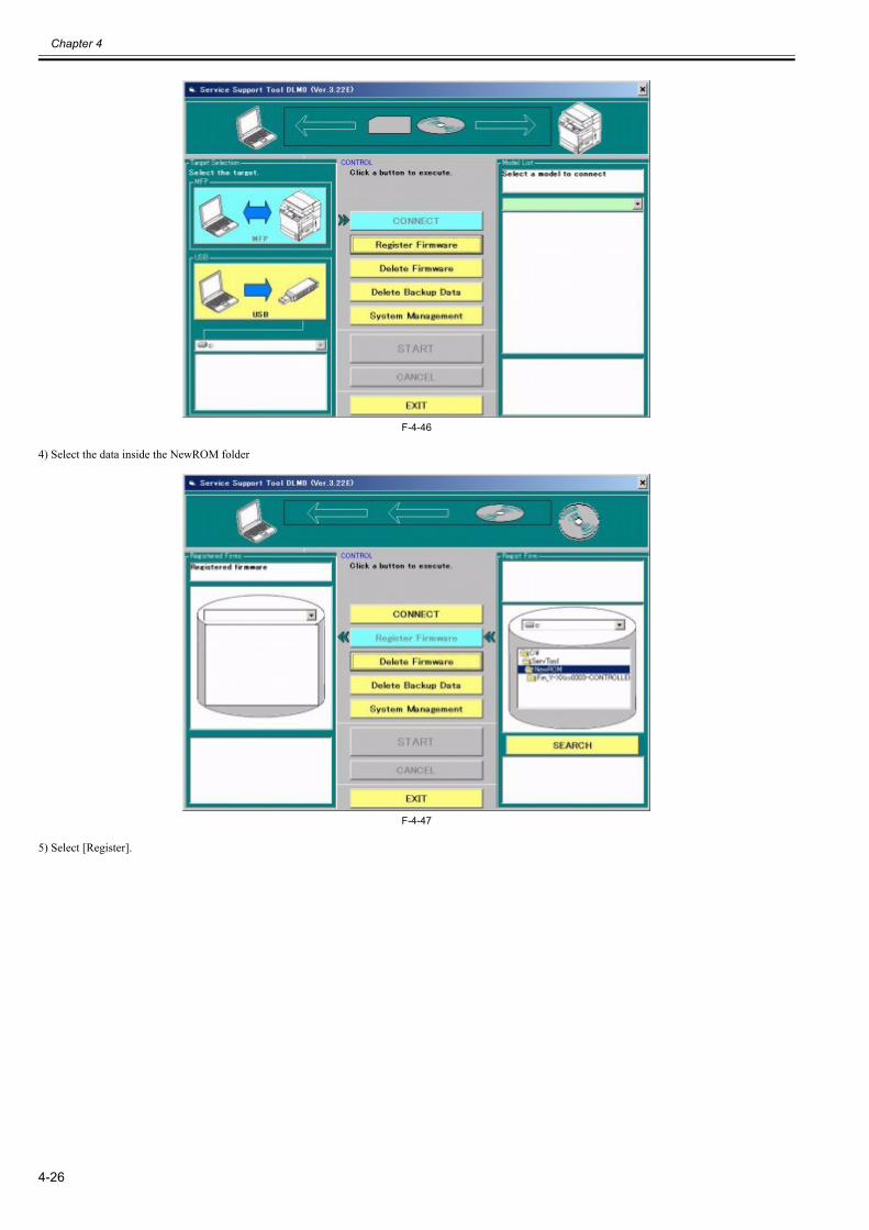
Chapter 4
4-26
F-4-46
4) Select the data inside the NewROM folder
F-4-47
5) Select [Register].
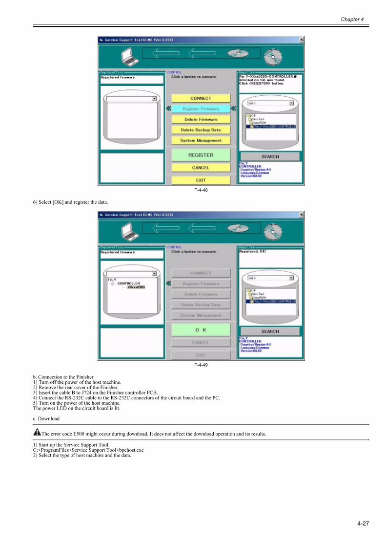
Chapter 4
4-27
F-4-48
6) Select [OK] and register the data.
F-4-49
b. Connection to the Finisher1) Turn off the power of the host machine.2) Remove the rear cover of the Finisher.3) Insert the cable B to J724 on the Finisher controller PCB.4) Connect the RS-232C cable to the RS-232C connectors of the circuit board and the PC.5) Turn on the power of the host machine.The power LED on the circuit board is lit.
c. Download
The error code E500 might occur during download. It does not affect the download operation and its results.
1) Start up the Service Support Tool.C:>ProgramFiles>Service Support Tool>bpchost.exe2) Select the type of host machine and the data.
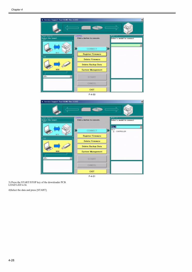
Chapter 4
4-28
F-4-50
F-4-51
3) Press the START/STOP key of the downloader PCB.LOAD LED is lit.
4)Select the data and press [START].
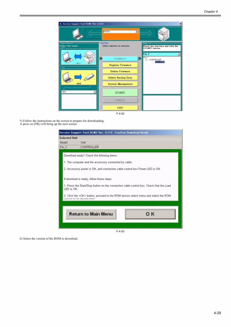
Chapter 4
4-29
F-4-52
5) Follow the instructions on the screen to prepare for downloading.A press on [OK] will bring up the next screen.
F-4-53
6) Select the version of the ROM to download.
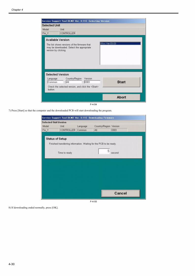
Chapter 4
4-30
F-4-54
7) Press [Start] so that the computer and the downloaded PCB will start downloading the program.
F-4-55
8) If downloading ended normally, press [OK].
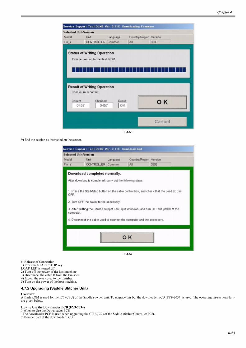
Chapter 4
4-31
F-4-56
9) End the session as instructed on the screen.
F-4-57
5. Release of Connection1) Press the START/STOP key.LOAD LED is turned off.2) Turn off the power of the host machine.3) Disconnect the cable B from the Finisher.4) Mount the rear cover to the Finisher.5) Turn on the power of the host machine.
4.7.2 Upgrading (Saddle Stitcher Unit)0023-6972
OverviewA flash ROM is used for the IC7 (CPU) of the Saddle stitcher unit. To upgrade this IC, the downloader PCB (FY9-2034) is used. The operating instructions for itare given below.
How to Use the Downloader PCB (FY9-2034)1.When to Use the Downloader PCB The downloader PCB is used when upgrading the CPU (IC7) of the Saddle stitcher Controller PCB.2.Member part of the downloader PCB
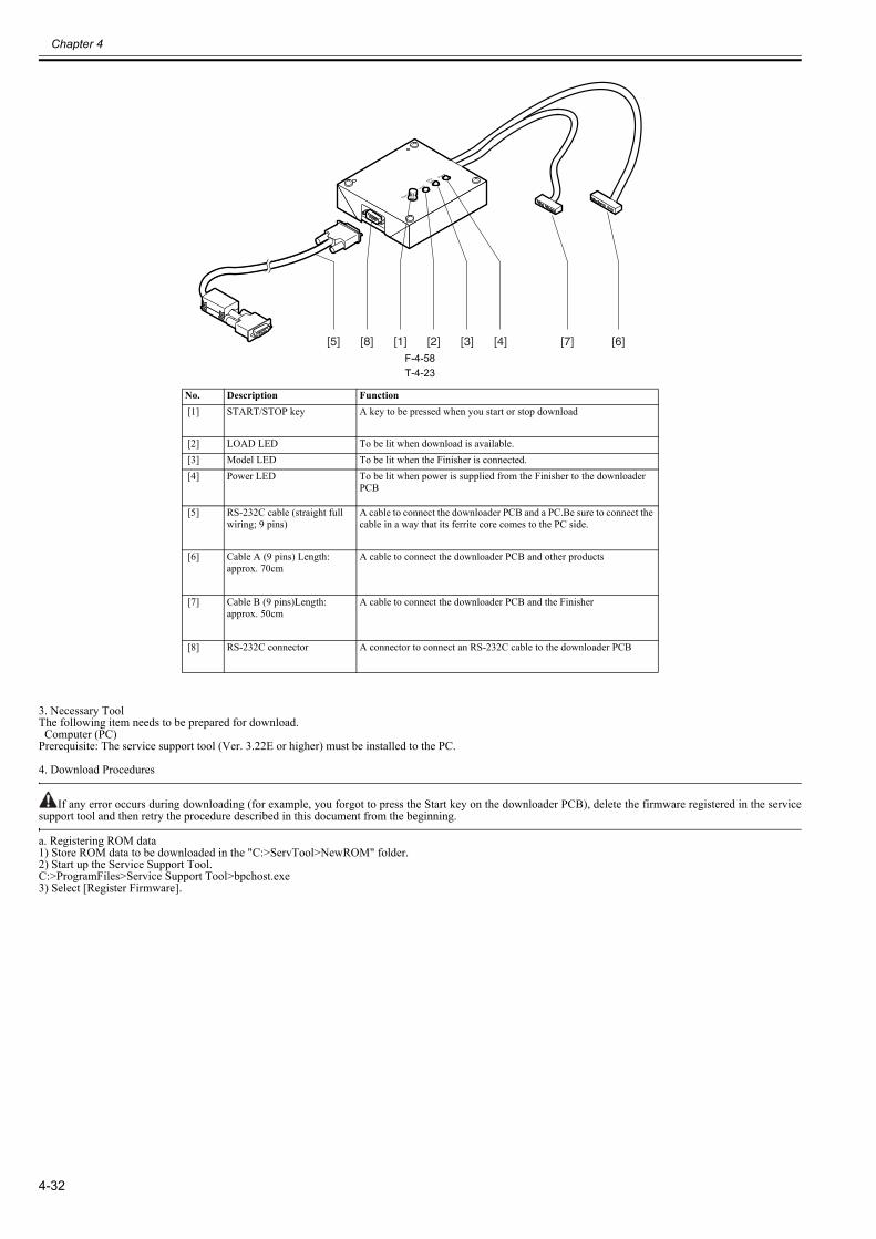
Chapter 4
4-32
F-4-58T-4-23
3. Necessary ToolThe following item needs to be prepared for download. Computer (PC)Prerequisite: The service support tool (Ver. 3.22E or higher) must be installed to the PC.
4. Download Procedures
If any error occurs during downloading (for example, you forgot to press the Start key on the downloader PCB), delete the firmware registered in the servicesupport tool and then retry the procedure described in this document from the beginning.
a. Registering ROM data1) Store ROM data to be downloaded in the "C:>ServTool>NewROM" folder.2) Start up the Service Support Tool.C:>ProgramFiles>Service Support Tool>bpchost.exe3) Select [Register Firmware].
No. Description Function [1] START/STOP key A key to be pressed when you start or stop download
[2] LOAD LED To be lit when download is available. [3] Model LED To be lit when the Finisher is connected. [4] Power LED To be lit when power is supplied from the Finisher to the downloader
PCB
[5] RS-232C cable (straight full wiring; 9 pins)
A cable to connect the downloader PCB and a PC.Be sure to connect the cable in a way that its ferrite core comes to the PC side.
[6] Cable A (9 pins) Length: approx. 70cm
A cable to connect the downloader PCB and other products
[7] Cable B (9 pins)Length: approx. 50cm
A cable to connect the downloader PCB and the Finisher
[8] RS-232C connector A connector to connect an RS-232C cable to the downloader PCB
[1] [2] [3] [4] [6][7][5] [8]
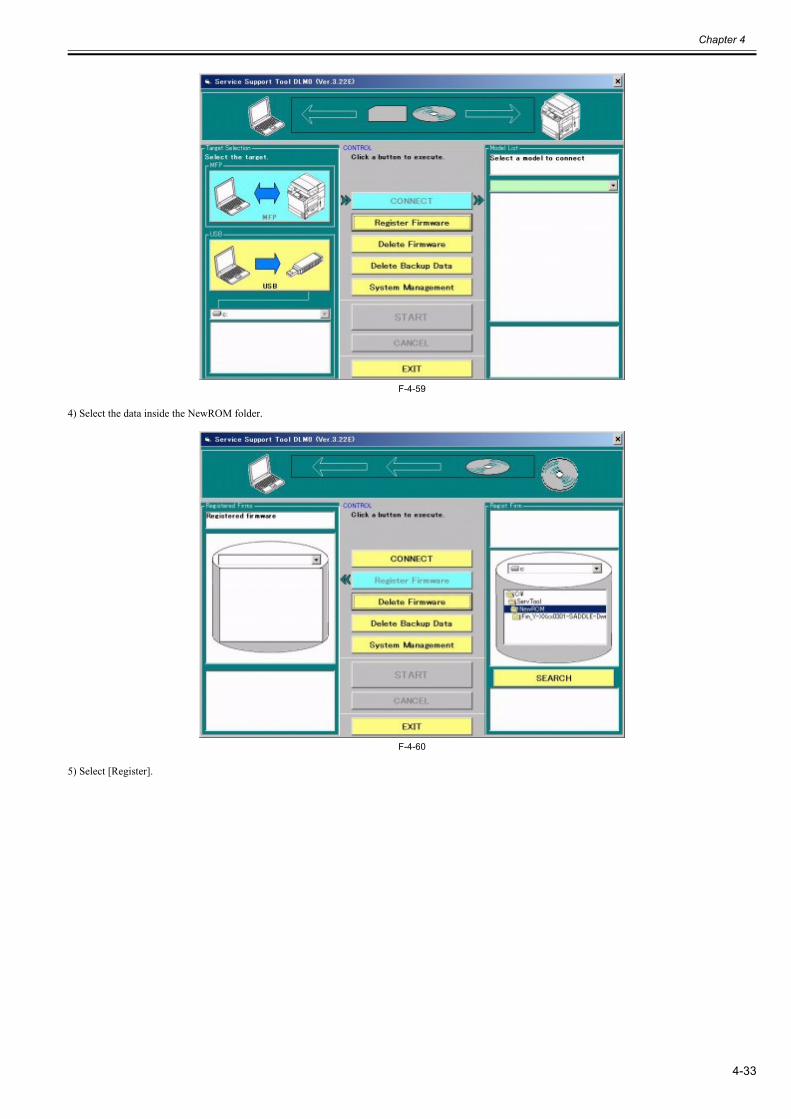
Chapter 4
4-33
F-4-59
4) Select the data inside the NewROM folder.
F-4-60
5) Select [Register].
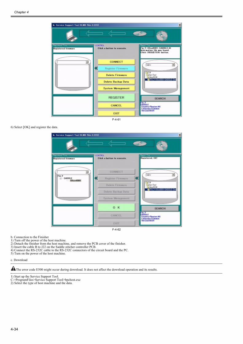
Chapter 4
4-34
F-4-61
6) Select [OK] and register the data.
F-4-62
b. Connection to the Finisher1) Turn off the power of the host machine.2) Detach the finisher from the host machine, and remove the PCB cover of the finisher.3) Insert the cable B to J22 on the Saddle stitcher controller PCB.4) Connect the RS-232C cable to the RS-232C connectors of the circuit board and the PC.5) Turn on the power of the host machine.
c. Download
The error code E500 might occur during download. It does not affect the download operation and its results.
1) Start up the Service Support Tool.C:>ProgramFiles>Service Support Tool>bpchost.exe2) Select the type of host machine and the data.
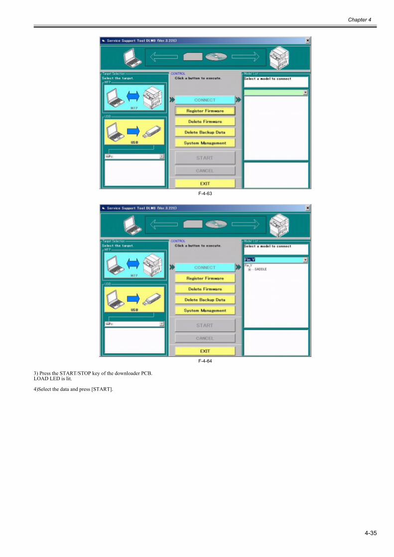
Chapter 4
4-35
F-4-63
F-4-64
3) Press the START/STOP key of the downloader PCB.LOAD LED is lit.
4)Select the data and press [START].
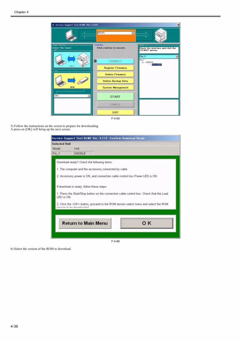
Chapter 4
4-36
F-4-65
5) Follow the instructions on the screen to prepare for downloading.A press on [OK] will bring up the next screen.
F-4-66
6) Select the version of the ROM to download.
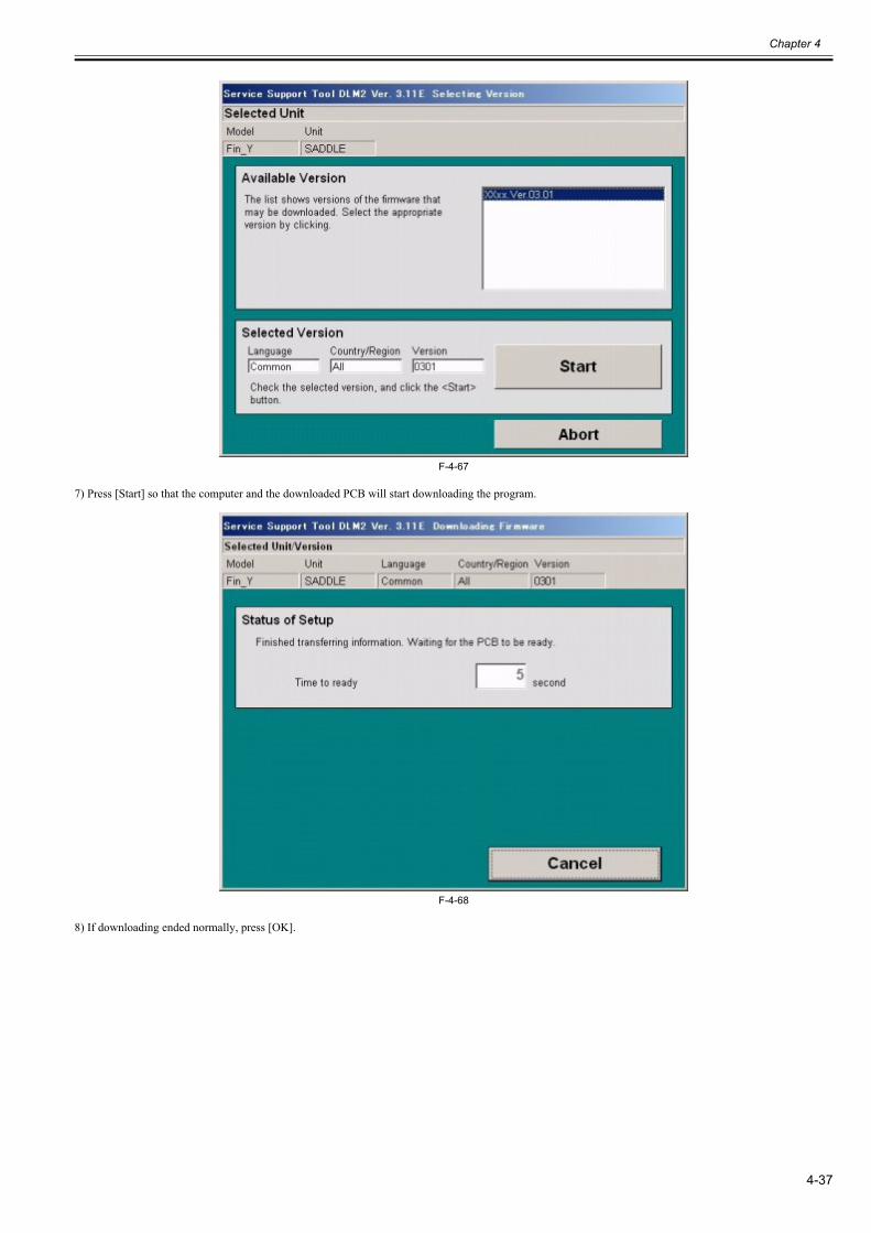
Chapter 4
4-37
F-4-67
7) Press [Start] so that the computer and the downloaded PCB will start downloading the program.
F-4-68
8) If downloading ended normally, press [OK].
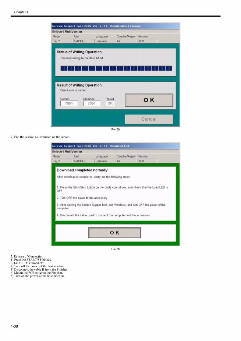
Chapter 4
4-38
F-4-69
9) End the session as instructed on the screen.
F-4-70
5. Release of Connection1) Press the START/STOP key.LOAD LED is turned off.2) Turn off the power of the host machine.3) Disconnect the cable B from the Finisher.4) Mount the PCB cover to the Finisher.5) Turn on the power of the host machine.

Chapter 4
4-39
4.8 Service Tools
4.8.1 Solvents and Oils0023-6973
T-4-24
No. Name Description Composition Remarks1 Vic Clean Cleaning:
e.g., glass,plastic, rubber parts, external covers
Hydrocarbon(fluorine family)AlcoholSurface activating agentWater
Do not bring near fire.Procure locally.Isopropyl alcohol may be substituted.
2 Lubricant Sliding units Silicone oil MOLYKOTE EM30-L


Chapter 5 Error Code

Contents
Contents
5.1 Overview........................................................................................................................................................................5-15.1.1 Overview...................................................................................................................................................................................... 5-1
5.2 User Error Code .............................................................................................................................................................5-15.2.1 Staple is absent............................................................................................................................................................................. 5-15.2.2 Stapler safety protection function activated................................................................................................................................. 5-15.2.3 Stack tray overstacking ................................................................................................................................................................ 5-15.2.4 Stapler staple jam......................................................................................................................................................................... 5-25.2.5 Staple is absent (Saddle Stitcher Unit)......................................................................................................................................... 5-25.2.6 Mixed paper sizes (Saddle Stitcher Unit) .................................................................................................................................... 5-25.2.7 Stack exceeded (Saddle Stitcher Unit)......................................................................................................................................... 5-25.2.8 Stitching capacity error (Saddle Stitcher Unit) ............................................................................................................................ 5-2
5.3 Service Error Code.........................................................................................................................................................5-35.3.1 E500 ............................................................................................................................................................................................. 5-35.3.2 E503 ............................................................................................................................................................................................. 5-35.3.3 E505 ............................................................................................................................................................................................. 5-35.3.4 E514 ............................................................................................................................................................................................. 5-35.3.5 E519 ............................................................................................................................................................................................. 5-35.3.6 E530 ............................................................................................................................................................................................. 5-45.3.7 E531 ............................................................................................................................................................................................. 5-45.3.8 E532 ............................................................................................................................................................................................. 5-45.3.9 E535 ............................................................................................................................................................................................. 5-45.3.10 E537 ........................................................................................................................................................................................... 5-55.3.11 E540 ........................................................................................................................................................................................... 5-55.3.12 E542 ........................................................................................................................................................................................... 5-55.3.13 E584 ........................................................................................................................................................................................... 5-55.3.14 E5F0........................................................................................................................................................................................... 5-65.3.15 E5F1........................................................................................................................................................................................... 5-65.3.16 E5F2........................................................................................................................................................................................... 5-65.3.17 E5F3........................................................................................................................................................................................... 5-65.3.18 E5F4........................................................................................................................................................................................... 5-75.3.19 E5F5........................................................................................................................................................................................... 5-75.3.20 E5F6........................................................................................................................................................................................... 5-75.3.21 E5F8........................................................................................................................................................................................... 5-85.3.22 E5F9........................................................................................................................................................................................... 5-85.3.23 Temporary Functional Limit...................................................................................................................................................... 5-8

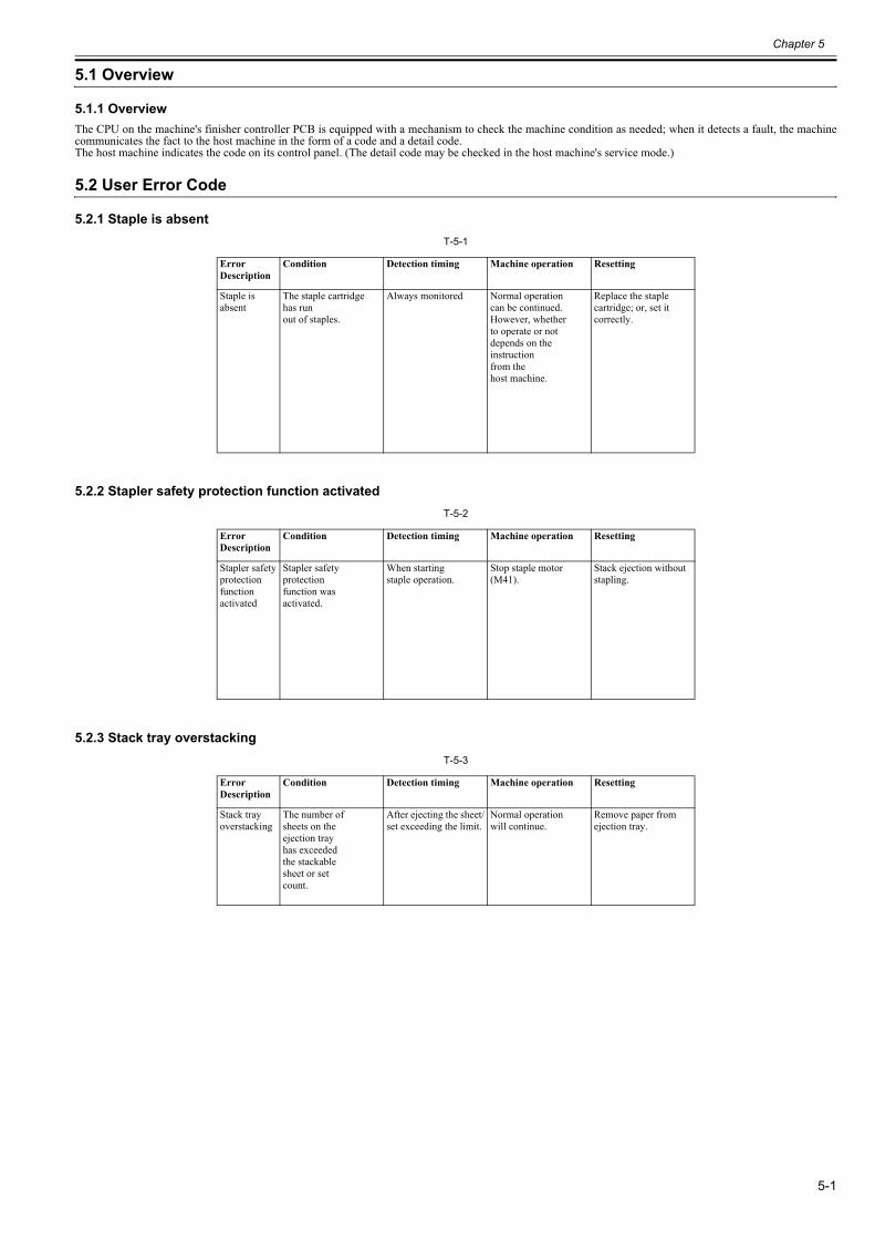
Chapter 5
5-1
5.1 Overview
5.1.1 Overview0023-7020
The CPU on the machine's finisher controller PCB is equipped with a mechanism to check the machine condition as needed; when it detects a fault, the machinecommunicates the fact to the host machine in the form of a code and a detail code.The host machine indicates the code on its control panel. (The detail code may be checked in the host machine's service mode.)
5.2 User Error Code
5.2.1 Staple is absent0023-7022
T-5-1
5.2.2 Stapler safety protection function activated0023-7024
T-5-2
5.2.3 Stack tray overstacking0023-7026
T-5-3
Error Description
Condition Detection timing Machine operation Resetting
Staple is absent
The staple cartridgehas runout of staples.
Always monitored Normal operationcan be continued.However, whetherto operate or notdepends on the instructionfrom thehost machine.
Replace the staplecartridge; or, set itcorrectly.
Error Description
Condition Detection timing Machine operation Resetting
Stapler safetyprotection functionactivated
Stapler safetyprotectionfunction wasactivated.
When startingstaple operation.
Stop staple motor (M41).
Stack ejection without stapling.
Error Description
Condition Detection timing Machine operation Resetting
Stack trayoverstacking
The number ofsheets on theejection trayhas exceededthe stackablesheet or setcount.
After ejecting the sheet/set exceeding the limit.
Normal operationwill continue.
Remove paper from ejection tray.
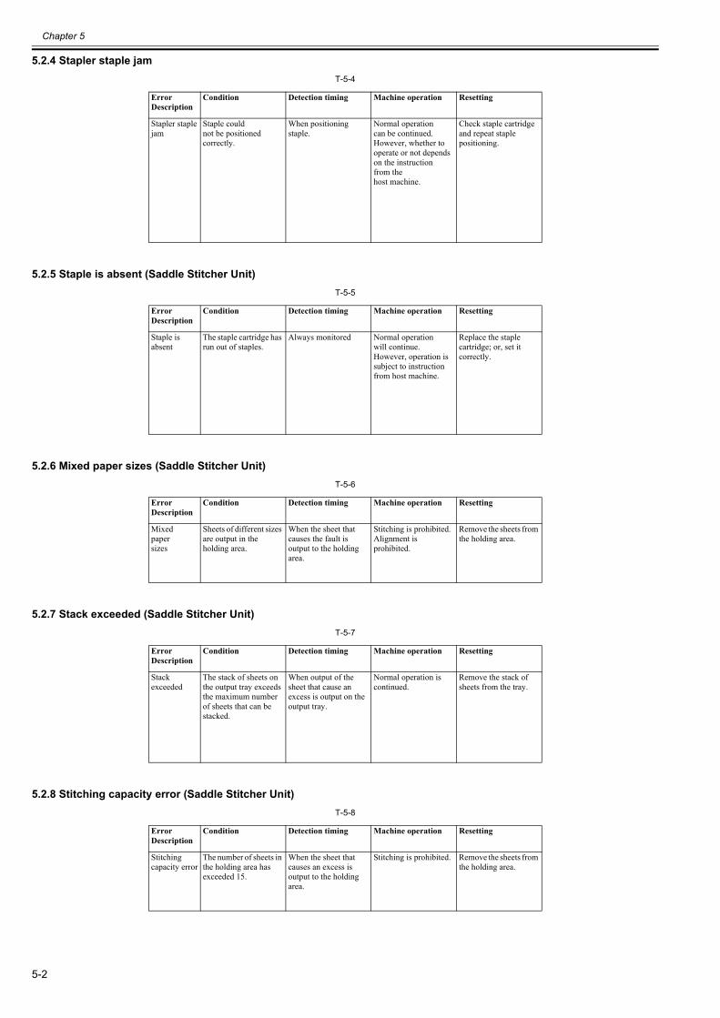
Chapter 5
5-2
5.2.4 Stapler staple jam0023-7028
T-5-4
5.2.5 Staple is absent (Saddle Stitcher Unit)0023-7029
T-5-5
5.2.6 Mixed paper sizes (Saddle Stitcher Unit)0023-7030
T-5-6
5.2.7 Stack exceeded (Saddle Stitcher Unit)0023-7031
T-5-7
5.2.8 Stitching capacity error (Saddle Stitcher Unit)0023-7032
T-5-8
Error Description
Condition Detection timing Machine operation Resetting
Stapler staplejam
Staple couldnot be positionedcorrectly.
When positioningstaple.
Normal operationcan be continued.However, whether to operate or not depends on the instructionfrom thehost machine.
Check staple cartridge and repeat staple positioning.
Error Description
Condition Detection timing Machine operation Resetting
Staple is absent
The staple cartridge has run out of staples.
Always monitored Normal operationwill continue. However, operation is subject to instruction from host machine.
Replace the staple cartridge; or, set it correctly.
Error Description
Condition Detection timing Machine operation Resetting
Mixedpapersizes
Sheets of different sizes are output in the holding area.
When the sheet that causes the fault is output to the holding area.
Stitching is prohibited. Alignment is prohibited.
Remove the sheets from the holding area.
Error Description
Condition Detection timing Machine operation Resetting
Stack exceeded
The stack of sheets on the output tray exceeds the maximum number of sheets that can be stacked.
When output of the sheet that cause an excess is output on the output tray.
Normal operation is continued.
Remove the stack of sheets from the tray.
Error Description
Condition Detection timing Machine operation Resetting
Stitching capacity error
The number of sheets in the holding area has exceeded 15.
When the sheet that causes an excess is output to the holding area.
Stitching is prohibited. Remove the sheets from the holding area.
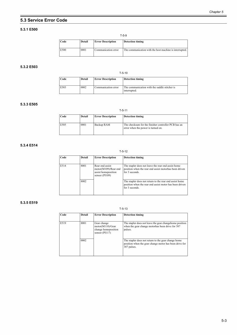
Chapter 5
5-3
5.3 Service Error Code
5.3.1 E5000023-7034
T-5-9
5.3.2 E5030023-7035
T-5-10
5.3.3 E5050023-7036
T-5-11
5.3.4 E5140023-7037
T-5-12
5.3.5 E5190023-7038
T-5-13
Code Detail Error Description Detection timing
E500 0001 Communication error The communication with the host machine is interrupted.
Code Detail Error Description Detection timing
E503 0002 Communication error The communication with the saddle stitcher is interrupted.
Code Detail Error Description Detection timing
E505 0001 Backup RAM The checksum for the finisher controller PCB has an error when the power is turned on.
Code Detail Error Description Detection timing
E514 8001 Rear end assist motor(M109)/Rear end assist homeposition sensor (PI109)
The stapler does not leave the rear end assist home position when the rear end assist motorhas been driven for 3 seconds.
8002 The stapler does not return to the rear end assist home position when the rear end assist motor has been driven for 3 seconds.
Code Detail Error Description Detection timing
E519 8001 Gear change motor(M110)/Gear change homeposition sensor (PI117)
The stapler does not leave the gear changehome position when the gear change motorhas been drive for 387 pulses.
0002 The stapler does not return to the gear change home position when the gear change motor has been drive for 387 pulses.
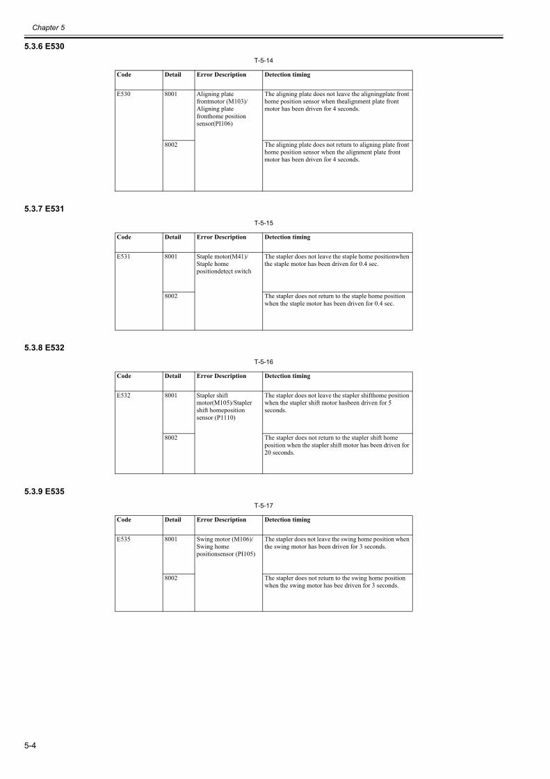
Chapter 5
5-4
5.3.6 E5300023-7039
T-5-14
5.3.7 E5310023-7040
T-5-15
5.3.8 E5320023-7041
T-5-16
5.3.9 E5350023-7043
T-5-17
Code Detail Error Description Detection timing
E530 8001 Aligning plate frontmotor (M103)/Aligning plate fronthome position sensor(PI106)
The aligning plate does not leave the aligningplate front home position sensor when thealignment plate front motor has been driven for 4 seconds.
8002 The aligning plate does not return to aligning plate front home position sensor when the alignment plate front motor has been driven for 4 seconds.
Code Detail Error Description Detection timing
E531 8001 Staple motor(M41)/Staple home positiondetect switch
The stapler does not leave the staple home positionwhen the staple motor has been driven for 0.4 sec.
8002 The stapler does not return to the staple home position when the staple motor has been driven for 0.4 sec.
Code Detail Error Description Detection timing
E532 8001 Stapler shift motor(M105)/Stapler shift homeposition sensor (P1110)
The stapler does not leave the stapler shifthome position when the stapler shift motor hasbeen driven for 5 seconds.
8002 The stapler does not return to the stapler shift home position when the stapler shift motor has been driven for 20 seconds.
Code Detail Error Description Detection timing
E535 8001 Swing motor (M106)/Swing home positionsensor (PI105)
The stapler does not leave the swing home position when the swing motor has been driven for 3 seconds.
8002 The stapler does not return to the swing home position when the swing motor has bee driven for 3 seconds.
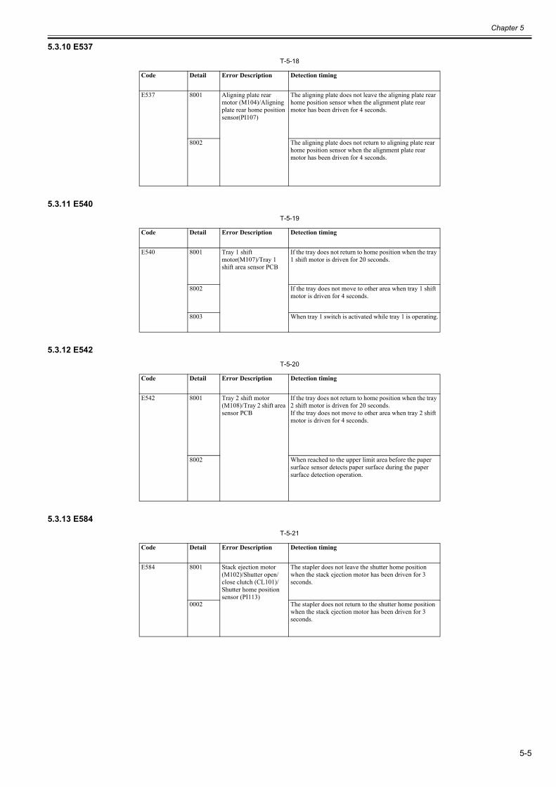
Chapter 5
5-5
5.3.10 E5370023-7044
T-5-18
5.3.11 E5400023-7045
T-5-19
5.3.12 E5420023-7046
T-5-20
5.3.13 E5840023-7047
T-5-21
Code Detail Error Description Detection timing
E537 8001 Aligning plate rear motor (M104)/Aligning plate rear home position sensor(PI107)
The aligning plate does not leave the aligning plate rear home position sensor when the alignment plate rear motor has been driven for 4 seconds.
8002 The aligning plate does not return to aligning plate rear home position sensor when the alignment plate rear motor has been driven for 4 seconds.
Code Detail Error Description Detection timing
E540 8001 Tray 1 shift motor(M107)/Tray 1 shift area sensor PCB
If the tray does not return to home position when the tray 1 shift motor is driven for 20 seconds.
8002 If the tray does not move to other area when tray 1 shift motor is driven for 4 seconds.
8003 When tray 1 switch is activated while tray 1 is operating.
Code Detail Error Description Detection timing
E542 8001 Tray 2 shift motor (M108)/Tray 2 shift area sensor PCB
If the tray does not return to home position when the tray 2 shift motor is driven for 20 seconds.If the tray does not move to other area when tray 2 shift motor is driven for 4 seconds.
8002 When reached to the upper limit area before the paper surface sensor detects paper surface during the paper surface detection operation.
Code Detail Error Description Detection timing
E584 8001 Stack ejection motor (M102)/Shutter open/close clutch (CL101)/Shutter home position sensor (PI113)
The stapler does not leave the shutter home position when the stack ejection motor has been driven for 3 seconds.
0002 The stapler does not return to the shutter home position when the stack ejection motor has been driven for 3 seconds.
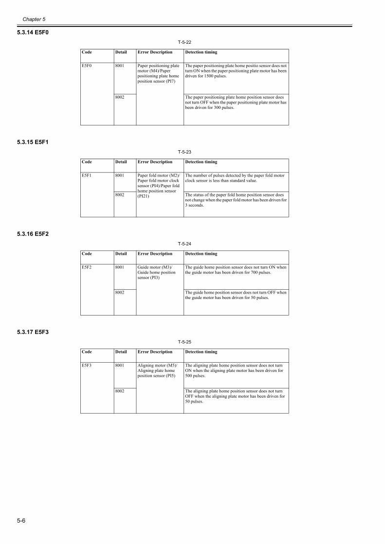
Chapter 5
5-6
5.3.14 E5F00023-7048
T-5-22
5.3.15 E5F10023-7049
T-5-23
5.3.16 E5F20023-7050
T-5-24
5.3.17 E5F30023-7051
T-5-25
Code Detail Error Description Detection timing
E5F0 8001 Paper positioning plate motor (M4)/Paper positioning plate home position sensor (PI7)
The paper positioning plate home positio sensor does not turn ON when the paper positioning plate motor has been driven for 1500 pulses.
8002 The paper positioning plate home position sensor does not turn OFF when the paper positioning plate motor has been driven for 300 pulses.
Code Detail Error Description Detection timing
E5F1 8001 Paper fold motor (M2)/Paper fold motor clock sensor (PI4)/Paper fold home position sensor (PI21)
The number of pulses detected by the paper fold motor clock sensor is less than standard value.
8002 The status of the paper fold home position sensor does not change when the paper fold motor has been driven for 3 seconds.
Code Detail Error Description Detection timing
E5F2 8001 Guide motor (M3)/Guide home position sensor (PI3)
The guide home position sensor does not turn ON when the guide motor has been driven for 700 pulses.
8002 The guide home position sensor does not turn OFF when the guide motor has been driven for 50 pulses.
Code Detail Error Description Detection timing
E5F3 8001 Aligning motor (M5)/ Aligning plate home position sensor (PI5)
The aligning plate home position sensor does not turn ON when the aligning plate motor has been driven for 500 pulses.
8002 The aligning plate home position sensor does not turn OFF when the aligning plate motor has been driven for 50 pulses.
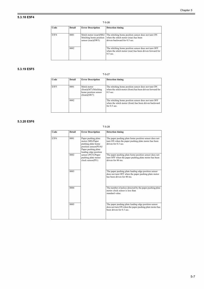
Chapter 5
5-7
5.3.18 E5F40023-7052
T-5-26
5.3.19 E5F50023-7053
T-5-27
5.3.20 E5F60023-7054
T-5-28
Code Detail Error Description Detection timing
E5F4 8001 Stitch motor (rear)(M6)/Stitching home position sensor (rear)(SW5)
The stitching home position sensor does not turn ON when the stitch motor (rear) has beendriven backward for 0.5 sec.
8002 The stitching home position sensor does not turn OFF when the stitch motor (rear) has been driven forward for 0.5 sec.
Code Detail Error Description Detection timing
E5F5 8001 Stitch motor (front)(M7)/Stitching home position sensor (front)(SW7)
The stitching home position sensor does not turn ON when the stitch motor (front) has been driven forward for 0.5 sec.
8002 The stitching home position sensor does not turn OFF when the stitch motor (front) has been driven backward for 0.5 sec.
Code Detail Error Description Detection timing
E5F6 8001 Paper pushing plate motor (M8)/Paper pushing plate home position sensor(PI14)/Paper pushing plate leading edge position sensor (PI15)/Paper pushing plate motor clock sensor(PI1)
The paper pushing plate home position sensor does not turn ON when the paper pushing plate motor has been driven for 0.3 sec.
8002 The paper pushing plate home position sensor does not turn OFF when the paper pushing plate motor has been driven for 80 ms.
8003 The paper pushing plate leading edge position sensor does not turn OFF when the paper pushing plate motor has been driven for 80 ms.
8004 The number of pulses detected by the paper pushing plate motor clock sensor is less thanstandard value.
8005 The paper pushing plate leading edge position sensor does not turn ON when the paper pushing plate motor has been driven for 0.3 sec.
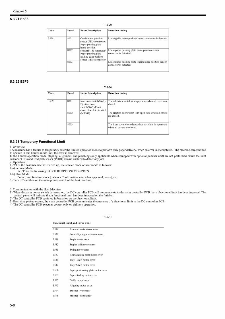
Chapter 5
5-8
5.3.21 E5F80023-7055
T-5-29
5.3.22 E5F90023-7056
T-5-30
5.3.23 Temporary Functional Limit0023-7058
1. OverviewThe machine has a feature to temporarily enter the limited operation mode to perform only paper delivery, when an error is encountered. The machine can continueto operate in this limited mode until the error is removed.In the limited operation mode, stapling, alignment, and punching (only applicable when equipped with optional puncher unit) are not performed, while the inletsensor (PI103) and feed path sensor (PI104) remain enabled to detect any jam.2. Operation1) When the host machine has started up, use service mode or user mode as follows:1-a) Service Mode
Set '1' for the following: SORTER>OPTION>MD-SPRTN.1-b) User Mode
Press [limit function mode]; when a Confirmation screen has appeared, press [yes].3) Turn off and then on the main power switch of the host machine.
3. Communication with the Host Machine1) When the main power switch is turned on, the DC controller PCB will communicate to the main controller PCB that a functional limit has been imposed. The
control panel will indicate that a functional limit has been imposed on the finisher.2) The DC controller PCB backs up information on the functional limit.3) Each time pickup occurs, the main controller PCB communicates the presence of a functional limit to the DC controller PCB.4) The DC controller PCB executes control only on delivery operation.
T-5-31
Code Detail Error Description Detection timing
E5F8 8001 Guide home position sensor (PI13) connector/Paper pushing plate home position sensor(PI14) connector/Paper pushing plate leading edge positionsensor (PI15) connector
Loose guide home position sensor connector is detected.
8002 Loose paper pushing plate home position sensor connector is detected.
8003 Loose paper pushing plate leading edge position sensor connector is detected.
Code Detail Error Description Detection timing
E5F9 8001 Inlet door switch(SW1)/Ejection door switch(SW3)/Front cover close detect switch (MS101)
The inlet door switch is in open state when all covers are closed.
8002 The ejection door switch is in open state when all covers are closed.
8003 The front cover close detect door switch is in open state when all covers are closed.
Functional Limit and Error Code
E514 Rear end assist motor error
E530 Front aligning plate motor error
E531 Staple motor error
E532 Stapler shift motor error
E535 Swing motor error
E537 Rear aligning plate motor error
E540 Tray 1 shift motor error
E542 Tray 2 shift motor error
E5F0 Paper positioning plate motor error
E5F1 Paper folding motor error
E5F2 Guide motor error
E5F3 Aligning motor error
E5F4 Stitcher (rear) error
E5F5 Stitcher (front) error

Chapter 5
5-9
E5F6 Paper pushing plate motor error
E5F8 Sensor connector
E5F9 Micro switch error
E590 Punch motor error
E591 Scrap full detector sensor error
E592 Trailing edge/Horizontal registration sensor error
E593 Horizontal registration motor error
* E590 to E593 are when equipped puncher unit (option).
Functional Limit and Error Code


Jul 17 2009