Embed Size (px)
Citation preview
iP4500 SIMPLIFIED SERVICE MANUAL
1. PRODUCT LIST 2. PRODUCT SPECIFICATIONS 3. ERROR DISPLAY 4. REPAIR 5. SERVICE MODE 6. SERVICE POLICY
QY8-13BI-000 Rev. 00
July 12, 2007 Canon Inc.
1
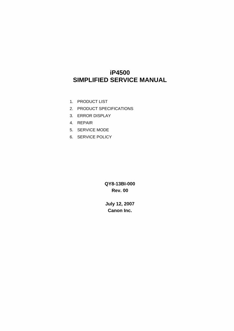
1. PRODUCT LIST 1-1. Main Units
Product name Product code Destination Production q'ty (for 3 months) Accessories
Q30-4400-000 2171B001AA JPN 180,000 Q30-4401-000 2171B002AA US
2171B003AA CA 2171B004AA LAM
39,000
--- EUM --- EMB
2171B008AA GB 2171B009AA EUM / EMB
58,000
2171B011AA AU 2171B012AA ASA 2171B013AA HK 2171B014AA CN
Q30-4400-000
2171B015AA TW
Canon Inkjet Printer iP4500
Q30-4401-000 2171B016AA KR
18,000
Print head Ink tanks (Japan /
Non-Japan) BCI-9BK / PGI-5BK BCI- 7eBK / CLI-8BK BCI- 7eC / CLI-8C BCI- 7eM / CLI-8M BCI- 7eY / CLI-8Y CD / DVD tray*1 8cm CD / DVD adapter*1 Power cord *1: US and KR
1-2. Consumables
Product name Product code Destination Remarks Canon Ink Tank BCI-9BK 0372B001AA BCI-7eBK 0364B001AA BCI-7eC 0365B001AA BCI-7eM 0366B001AA BCI-7eY 0367B001AA
JP
Canon Ink Tank PGI-5BK 0628B001AA to 0628B005AA CLI-8BK 0620B001AA to 0620B005AA CLI-8C 0621B001AA to 0621B005AA CLI-8M 0622B001AA to 0622B005AA CLI-8Y 0623B001AA to 0623B005AA
001: EUR / OCN 002: AMR 003: ASA 004: W/O BOX 005: AMR S
1-3. Options None
2
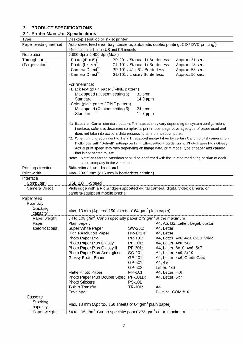
2. PRODUCT SPECIFICATIONS 2-1. Printer Main Unit Specifications Type Desktop serial color inkjet printer Paper feeding method Auto sheet feed (rear tray, cassette, automatic duplex printing, CD / DVD printing*)
* Not supported in the US and KR models Resolution 9,600 dpi x 2,400 dpi (Max.) Throughput (Target value)
- Photo (4" x 6")*1 PP-201 / Standard / Borderless: Approx. 21 sec. - Photo (L size)*1 GL-101 / Standard / Borderless: Approx. 18 sec. - Camera Direct*2 PP-101 / 4" x 6" / Borderless: Approx. 58 sec. - Camera Direct*2 GL-101 / L size / Borderless: Approx. 50 sec. For reference: - Black text (plain paper / FINE pattern) Max speed (Custom setting 5): 31 ppm Standard: 14.9 ppm - Color (plain paper / FINE pattern) Max speed (Custom setting 5): 24 ppm Standard: 11.7 ppm *1: Based on Canon standard pattern. Print speed may vary depending on system configuration,
interface, software, document complexity, print mode, page coverage, type of paper used and does not take into account data processing time on host computer.
*2: When printing equivalent to the 7.1megapixel image taken by certain Canon digital camera from PictBridge with “Default” settings on Print Effect without border using Photo Paper Plus Glossy. Actual print speed may vary depending on image data, print mode, type of paper and camera that is connected to, etc.
Note: Notations for the Americas should be confirmed with the related marketing section of each sales company in the Americas.
Printing direction Bidirectional, uni-directional Print width Max. 203.2 mm (216 mm in borderless printing) Interface Computer USB 2.0 Hi-Speed Camera Direct PictBridge with a PictBridge-supported digital camera, digital video camera, or
camera-equipped mobile phone Paper feed Rear tray Stacking
capacity Max. 13 mm (Approx. 150 sheets of 64 g/m2 plain paper)
Paper weight 64 to 105 g/m2, Canon specialty paper 273 g/m2 at the maximum Paper
specifications Plain paper: A4, A5, B5, Letter, Legal, custom Super White Paper SW-201: A4, Letter High Resolution Paper HR-101N: A4, Letter Photo Paper Pro PR-101: A4, Letter, 4x6, 4x8, 8x10, Wide Photo Paper Plus Glossy PP-101: A4, Letter, 4x6, 5x7 Photo Paper Plus Glossy II PP-201: A4, Letter, 8x10, 4x6, 5x7 Photo Paper Plus Semi-gloss SG-201: A4, Letter, 4x6, 8x10 Glossy Photo Paper GP-401: A4, Letter, 4x6, Credit Card GP-501: A4, 4x6 GP-502: Letter, 4x6 Matte Photo Paper MP-101: A4, Letter, 4x6 Photo Paper Plus Double Sided PP-101D: A4, Letter, 5x7 Photo Stickers PS-101 T-shirt Transfer TR-301: A4 Envelope: DL-size, COM #10
Cassette Stacking
capacity Max. 13 mm (Approx. 150 sheets of 64 g/m2 plain paper)
Paper weight 64 to 105 g/m2, Canon specialty paper 273 g/m2 at the maximum
3
Paper specifications
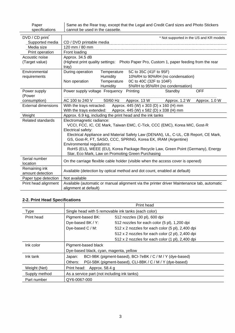
Same as the Rear tray, except that the Legal and Credit Card sizes and Photo Stickers cannot be used in the cassette.
2-2. Print Head Specifications
Print head Type Single head with 5 removable ink tanks (each color) Print head Pigment-based BK: 512 nozzles (30 pl), 600 dpi
Dye-based BK / Y: 512 nozzles for each color (5 pl), 1,200 dpi Dye-based C / M: 512 x 2 nozzles for each color (5 pl), 2,400 dpi 512 x 2 nozzles for each color (2 pl), 2,400 dpi 512 x 2 nozzles for each color (1 pl), 2,400 dpi
Ink color Pigment-based black Dye-based black, cyan, magenta, yellow
Ink tank Japan: BCI-9BK (pigment-based), BCI-7eBK / C / M / Y (dye-based) Others: PGI-5BK (pigment-based), CLI-8BK / C / M / Y (dye-based)
Weight (Net) Print head: Approx. 58.4 g Supply method As a service part (not including ink tanks) Part number QY6-0067-000
DVD / CD print* * Not supported in the US and KR models Supported media CD / DVD printable media Media size 120 mm / 80 mm Print operation Front loading Acoustic noise (Target value)
Approx. 34.5 dB (Highest print quality settings: Photo Paper Pro, Custom 1, paper feeding from the rear tray)
Environmental requirements
During operation Temperature 5C to 35C (41F to 95F) Humidity 10%RH to 90%RH (no condensation) Non operation Temperature 0C to 40C (32F to 104F) Humidity 5%RH to 95%RH (no condensation)
Power supply (Power consumption)
Power supply voltage Frequency Printing Standby OFF AC 100 to 240 V 50/60 Hz Approx. 13 W Approx. 1.2 W Approx. 1.0 W
External dimensions With the trays retracted: Approx. 445 (W) x 303 (D) x 160 (H) mm With the trays extended: Approx. 445 (W) x 582 (D) x 338 (H) mm
Weight Approx. 6.9 kg, including the print head and the ink tanks Related standards Electromagnetic radiance:
VCCI, FCC, IC, CE Mark, Taiwan EMC, C-Tick, CCC (EMC), Korea MIC, Gost-R Electrical safety: Electrical Appliance and Material Safety Law (DENAN), UL, C-UL, CB Report, CE Mark,
GS, Gost-R, FT, SASO, CCC, SPRING, Korea EK, IRAM (Argentine) Environmental regulations: RoHS (EU), WEEE (EU), Korea Package Recycle Law, Green Point (Germany), Energy
Star, Eco Mark, Law on Promoting Green Purchasing Serial number location On the carriage flexible cable holder (visible when the access cover is opened)
Remaining ink amount detection Available (detection by optical method and dot count, enabled at default)
Paper type detection Not available Print head alignment Available (automatic or manual alignment via the printer driver Maintenance tab, automatic
alignment at default)

4
2-3. Supported Ink Tanks Pigment-based
ink Dye-based ink
Model Destination BCI- 9BK
PGI- 5BK
BIC- 7eBK
BCI- 7eC
BIC- 7eM
BCI- 7eY
CLI- 8BK
CLI- 8C
CLI- 8M
CLI- 8Y
Japan O X O O O O X X X X iP4500 Others X O X X X X O O O O
O: Usable X: Not usable Note: The ink tanks for the Japanese model are not compatible with those for the other models. Be
sure to use the appropriate ink tanks in servicing.
5
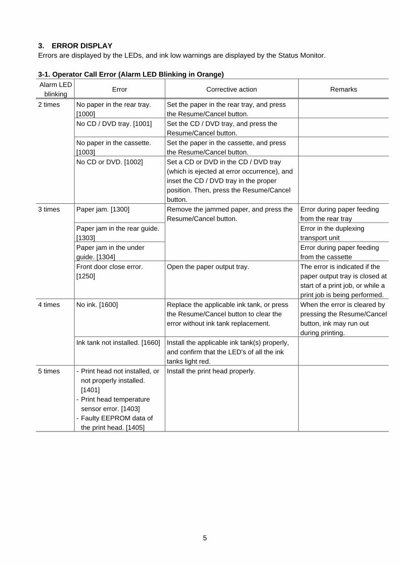
3. ERROR DISPLAY Errors are displayed by the LEDs, and ink low warnings are displayed by the Status Monitor. 3-1. Operator Call Error (Alarm LED Blinking in Orange) Alarm LED
blinking Error Corrective action Remarks
No paper in the rear tray. [1000]
Set the paper in the rear tray, and press the Resume/Cancel button.
No CD / DVD tray. [1001] Set the CD / DVD tray, and press the Resume/Cancel button.
No paper in the cassette. [1003]
Set the paper in the cassette, and press the Resume/Cancel button.
2 times
No CD or DVD. [1002] Set a CD or DVD in the CD / DVD tray (which is ejected at error occurrence), and inset the CD / DVD tray in the proper position. Then, press the Resume/Cancel button.
Paper jam. [1300] Error during paper feeding from the rear tray
Paper jam in the rear guide. [1303]
Error in the duplexing transport unit
Paper jam in the under guide. [1304]
Remove the jammed paper, and press the Resume/Cancel button.
Error during paper feeding from the cassette
3 times
Front door close error. [1250]
Open the paper output tray. The error is indicated if the paper output tray is closed at start of a print job, or while a print job is being performed.
No ink. [1600] Replace the applicable ink tank, or press the Resume/Cancel button to clear the error without ink tank replacement.
When the error is cleared by pressing the Resume/Cancel button, ink may run out during printing.
4 times
Ink tank not installed. [1660] Install the applicable ink tank(s) properly, and confirm that the LED's of all the ink tanks light red.
5 times - Print head not installed, or not properly installed. [1401]
- Print head temperature sensor error. [1403]
- Faulty EEPROM data of the print head. [1405]
Install the print head properly.
6
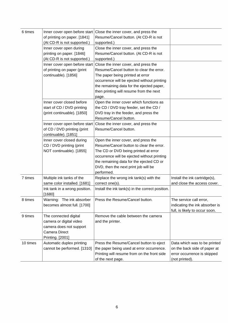
Inner cover open before start of printing on paper. [1841] (At CD-R is not supported.)
Close the inner cover, and press the Resume/Cancel button. (At CD-R is not supported.)
Inner cover open during printing on paper. [1846] (At CD-R is not supported.)
Close the inner cover, and press the Resume/Cancel button. (At CD-R is not supported.)
Inner cover open before start of printing on paper (print continuable). [1856]
Close the inner cover, and press the Resume/Cancel button to clear the error. The paper being printed at error occurrence will be ejected without printing the remaining data for the ejected paper, then printing will resume from the next page.
Inner cover closed before start of CD / DVD printing (print continuable). [1850]
Open the inner cover which functions as the CD / DVD tray feeder, set the CD / DVD tray in the feeder, and press the Resume/Cancel button.
Inner cover open before start of CD / DVD printing (print continuable). [1851]
Close the inner cover, and press the Resume/Cancel button.
6 times
Inner cover closed during CD / DVD printing (print NOT continuable). [1855]
Open the inner cover, and press the Resume/Cancel button to clear the error. The CD or DVD being printed at error occurrence will be ejected without printing the remaining data for the ejected CD or DVD, then the next print job will be performed.
Multiple ink tanks of the same color installed. [1681]
Replace the wrong ink tank(s) with the correct one(s).
Install the ink cartridge(s), and close the access cover.
7 times
Ink tank in a wrong position. [1680]
Install the ink tank(s) in the correct position.
8 times Warning: The ink absorber becomes almost full. [1700]
Press the Resume/Cancel button. The service call error, indicating the ink absorber is full, is likely to occur soon.
9 times The connected digital camera or digital video camera does not support Camera Direct Printing. [2001]
Remove the cable between the camera and the printer.
10 times Automatic duplex printing cannot be performed. [1310]
Press the Resume/Cancel button to eject the paper being used at error occurrence. Printing will resume from on the front side of the next page.
Data which was to be printed on the back side of paper at error occurrence is skipped (not printed).
7
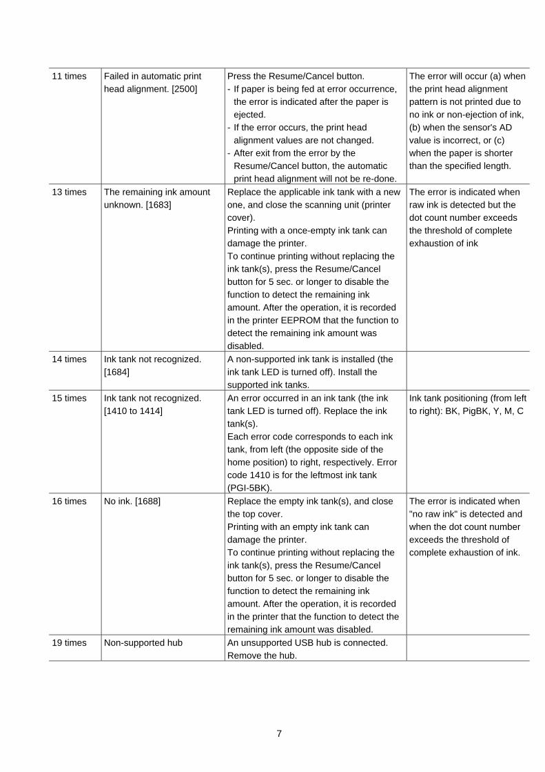
11 times Failed in automatic print
head alignment. [2500] Press the Resume/Cancel button. - If paper is being fed at error occurrence,
the error is indicated after the paper is ejected.
- If the error occurs, the print head alignment values are not changed.
- After exit from the error by the Resume/Cancel button, the automatic print head alignment will not be re-done.
The error will occur (a) when the print head alignment pattern is not printed due to no ink or non-ejection of ink, (b) when the sensor's AD value is incorrect, or (c) when the paper is shorter than the specified length.
13 times The remaining ink amount unknown. [1683]
Replace the applicable ink tank with a new one, and close the scanning unit (printer cover). Printing with a once-empty ink tank can damage the printer. To continue printing without replacing the ink tank(s), press the Resume/Cancel button for 5 sec. or longer to disable the function to detect the remaining ink amount. After the operation, it is recorded in the printer EEPROM that the function to detect the remaining ink amount was disabled.
The error is indicated when raw ink is detected but the dot count number exceeds the threshold of complete exhaustion of ink
14 times Ink tank not recognized. [1684]
A non-supported ink tank is installed (the ink tank LED is turned off). Install the supported ink tanks.
15 times Ink tank not recognized. [1410 to 1414]
An error occurred in an ink tank (the ink tank LED is turned off). Replace the ink tank(s). Each error code corresponds to each ink tank, from left (the opposite side of the home position) to right, respectively. Error code 1410 is for the leftmost ink tank (PGI-5BK).
Ink tank positioning (from left to right): BK, PigBK, Y, M, C
16 times No ink. [1688] Replace the empty ink tank(s), and close the top cover. Printing with an empty ink tank can damage the printer. To continue printing without replacing the ink tank(s), press the Resume/Cancel button for 5 sec. or longer to disable the function to detect the remaining ink amount. After the operation, it is recorded in the printer that the function to detect the remaining ink amount was disabled.
The error is indicated when "no raw ink" is detected and when the dot count number exceeds the threshold of complete exhaustion of ink.
19 times Non-supported hub An unsupported USB hub is connected. Remove the hub.
8
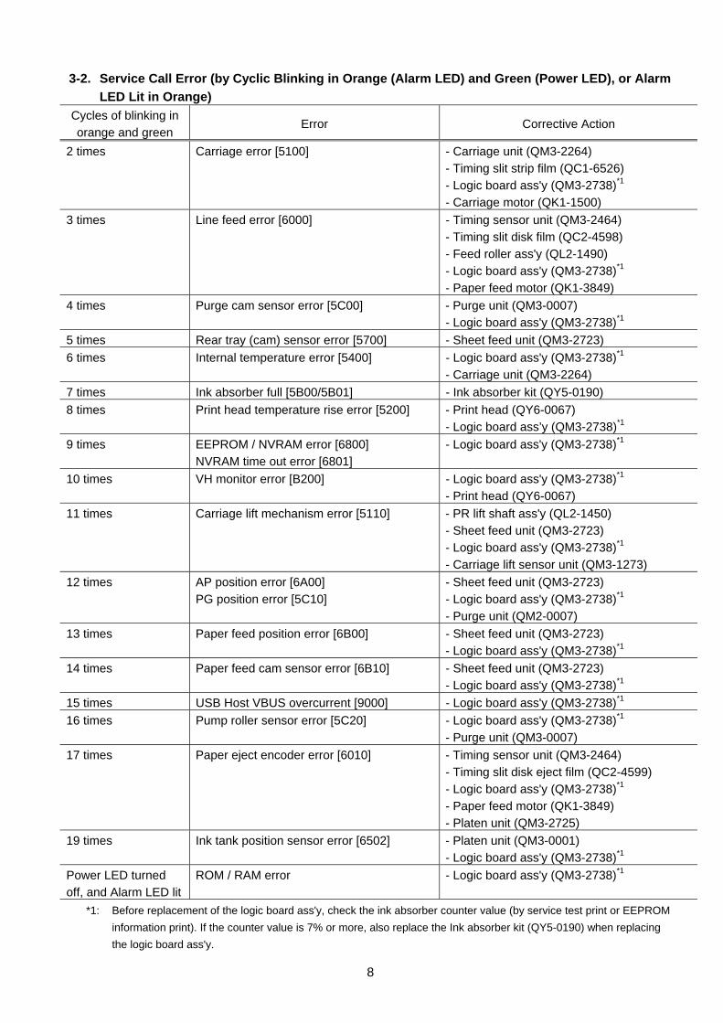
3-2. Service Call Error (by Cyclic Blinking in Orange (Alarm LED) and Green (Power LED), or Alarm LED Lit in Orange)
Cycles of blinking in orange and green
Error Corrective Action
2 times Carriage error [5100] - Carriage unit (QM3-2264) - Timing slit strip film (QC1-6526) - Logic board ass'y (QM3-2738)*1 - Carriage motor (QK1-1500)
3 times Line feed error [6000] - Timing sensor unit (QM3-2464) - Timing slit disk film (QC2-4598) - Feed roller ass'y (QL2-1490) - Logic board ass'y (QM3-2738)*1
- Paper feed motor (QK1-3849) 4 times Purge cam sensor error [5C00] - Purge unit (QM3-0007)
- Logic board ass'y (QM3-2738)*1 5 times Rear tray (cam) sensor error [5700] - Sheet feed unit (QM3-2723) 6 times Internal temperature error [5400] - Logic board ass'y (QM3-2738)*1
- Carriage unit (QM3-2264) 7 times Ink absorber full [5B00/5B01] - Ink absorber kit (QY5-0190) 8 times Print head temperature rise error [5200] - Print head (QY6-0067)
- Logic board ass’y (QM3-2738)*1 9 times EEPROM / NVRAM error [6800]
NVRAM time out error [6801] - Logic board ass'y (QM3-2738)*1
10 times VH monitor error [B200] - Logic board ass'y (QM3-2738)*1 - Print head (QY6-0067)
11 times Carriage lift mechanism error [5110] - PR lift shaft ass'y (QL2-1450) - Sheet feed unit (QM3-2723) - Logic board ass'y (QM3-2738)*1 - Carriage lift sensor unit (QM3-1273)
12 times AP position error [6A00] PG position error [5C10]
- Sheet feed unit (QM3-2723) - Logic board ass'y (QM3-2738)*1 - Purge unit (QM2-0007)
13 times Paper feed position error [6B00] - Sheet feed unit (QM3-2723) - Logic board ass'y (QM3-2738)*1
14 times Paper feed cam sensor error [6B10] - Sheet feed unit (QM3-2723) - Logic board ass'y (QM3-2738)*1
15 times USB Host VBUS overcurrent [9000] - Logic board ass'y (QM3-2738)*1 16 times Pump roller sensor error [5C20] - Logic board ass'y (QM3-2738)*1
- Purge unit (QM3-0007) 17 times Paper eject encoder error [6010] - Timing sensor unit (QM3-2464)
- Timing slit disk eject film (QC2-4599) - Logic board ass'y (QM3-2738)*1 - Paper feed motor (QK1-3849) - Platen unit (QM3-2725)
19 times Ink tank position sensor error [6502] - Platen unit (QM3-0001) - Logic board ass'y (QM3-2738)*1
Power LED turned off, and Alarm LED lit
ROM / RAM error - Logic board ass'y (QM3-2738)*1
*1: Before replacement of the logic board ass'y, check the ink absorber counter value (by service test print or EEPROM information print). If the counter value is 7% or more, also replace the Ink absorber kit (QY5-0190) when replacing the logic board ass'y.

9
3-3. Warnings
(1) Printer (No LED indication) Displayed warning Remarks
Ink low Status indication only. Print head temperature rise If the print head temperature is high when the top cover
is opened, the warning is displayed*1. When the print head temperature falls, the warning is released.
Protection of excess rise of the print head temperature
If the print head temperature exceeds the specified limit, a Wait is inserted during printing,
*1: If the warning is displayed, the carriage does not move to the ink tank replacement position when the top cover is opened.
10
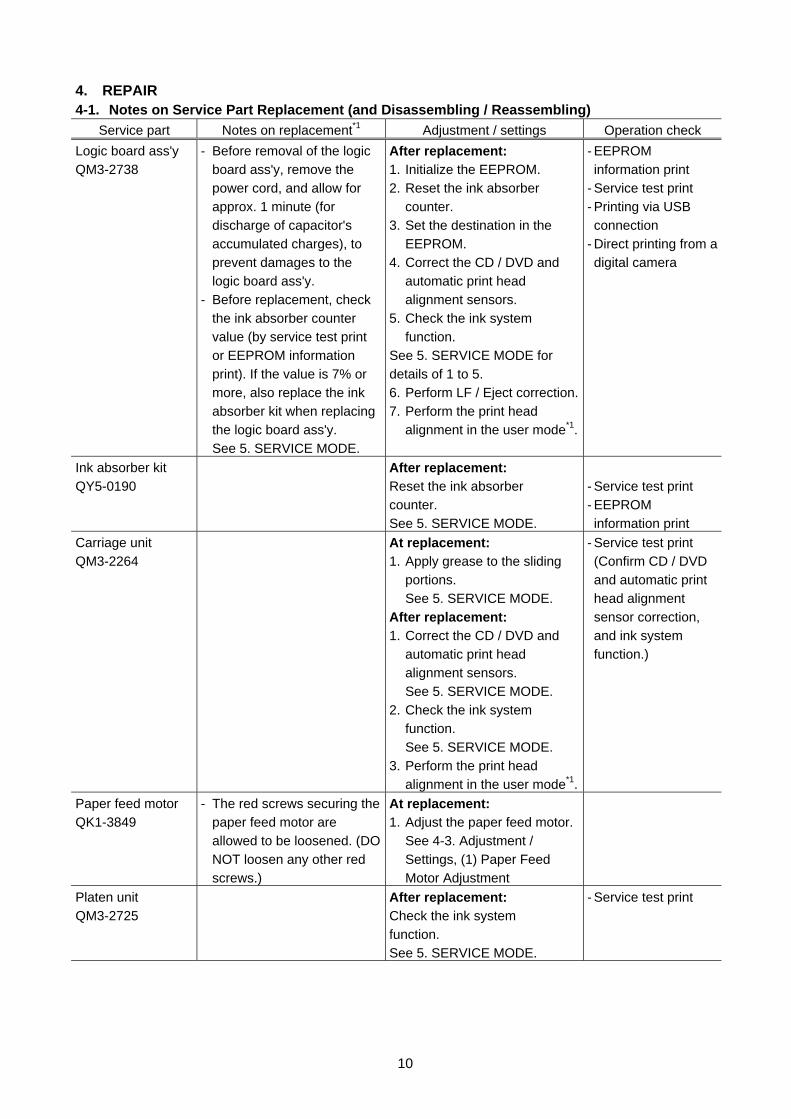
4. REPAIR 4-1. Notes on Service Part Replacement (and Disassembling / Reassembling)
Service part Notes on replacement*1 Adjustment / settings Operation check Logic board ass'y QM3-2738
- Before removal of the logic board ass'y, remove the power cord, and allow for approx. 1 minute (for discharge of capacitor's accumulated charges), to prevent damages to the logic board ass'y.
- Before replacement, check the ink absorber counter value (by service test print or EEPROM information print). If the value is 7% or more, also replace the ink absorber kit when replacing the logic board ass'y.
See 5. SERVICE MODE.
After replacement: 1. Initialize the EEPROM. 2. Reset the ink absorber
counter. 3. Set the destination in the
EEPROM. 4. Correct the CD / DVD and
automatic print head alignment sensors.
5. Check the ink system function.
See 5. SERVICE MODE for details of 1 to 5. 6. Perform LF / Eject correction. 7. Perform the print head
alignment in the user mode*1.
- EEPROM information print
- Service test print - Printing via USB connection
- Direct printing from a digital camera
Ink absorber kit QY5-0190
After replacement: Reset the ink absorber counter. See 5. SERVICE MODE.
- Service test print - EEPROM information print
Carriage unit QM3-2264
At replacement: 1. Apply grease to the sliding
portions. See 5. SERVICE MODE.
After replacement: 1. Correct the CD / DVD and
automatic print head alignment sensors. See 5. SERVICE MODE.
2. Check the ink system function. See 5. SERVICE MODE.
3. Perform the print head alignment in the user mode*1.
- Service test print (Confirm CD / DVD and automatic print head alignment sensor correction, and ink system function.)
Paper feed motor QK1-3849
- The red screws securing the paper feed motor are allowed to be loosened. (DO NOT loosen any other red screws.)
At replacement: 1. Adjust the paper feed motor.
See 4-3. Adjustment / Settings, (1) Paper Feed Motor Adjustment
Platen unit QM3-2725
After replacement: Check the ink system function. See 5. SERVICE MODE.
- Service test print
11
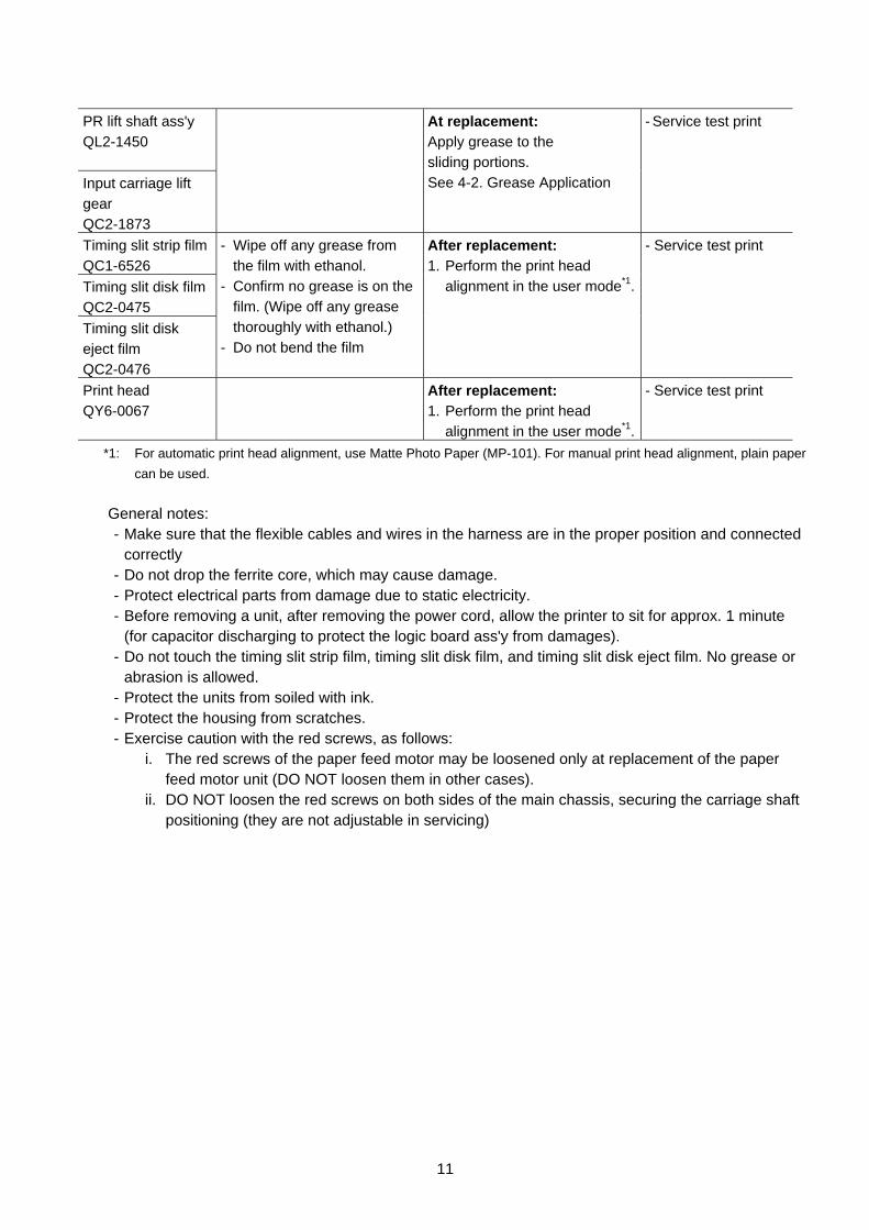
PR lift shaft ass'y QL2-1450 Input carriage lift gear QC2-1873
At replacement: Apply grease to the sliding portions. See 4-2. Grease Application
- Service test print
Timing slit strip film QC1-6526 Timing slit disk film QC2-0475 Timing slit disk eject film QC2-0476
- Wipe off any grease from the film with ethanol.
- Confirm no grease is on the film. (Wipe off any grease thoroughly with ethanol.)
- Do not bend the film
After replacement: 1. Perform the print head
alignment in the user mode*1.
- Service test print
Print head QY6-0067
After replacement: 1. Perform the print head
alignment in the user mode*1.
- Service test print
*1: For automatic print head alignment, use Matte Photo Paper (MP-101). For manual print head alignment, plain paper can be used.
General notes:
- Make sure that the flexible cables and wires in the harness are in the proper position and connected correctly
- Do not drop the ferrite core, which may cause damage. - Protect electrical parts from damage due to static electricity. - Before removing a unit, after removing the power cord, allow the printer to sit for approx. 1 minute
(for capacitor discharging to protect the logic board ass'y from damages). - Do not touch the timing slit strip film, timing slit disk film, and timing slit disk eject film. No grease or
abrasion is allowed. - Protect the units from soiled with ink. - Protect the housing from scratches. - Exercise caution with the red screws, as follows: i. The red screws of the paper feed motor may be loosened only at replacement of the paper
feed motor unit (DO NOT loosen them in other cases). ii. DO NOT loosen the red screws on both sides of the main chassis, securing the carriage shaft
positioning (they are not adjustable in servicing)
12
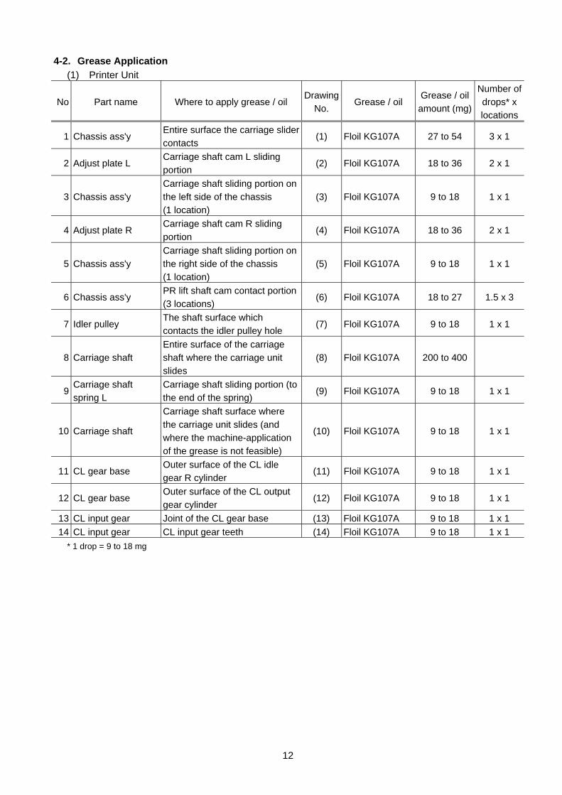
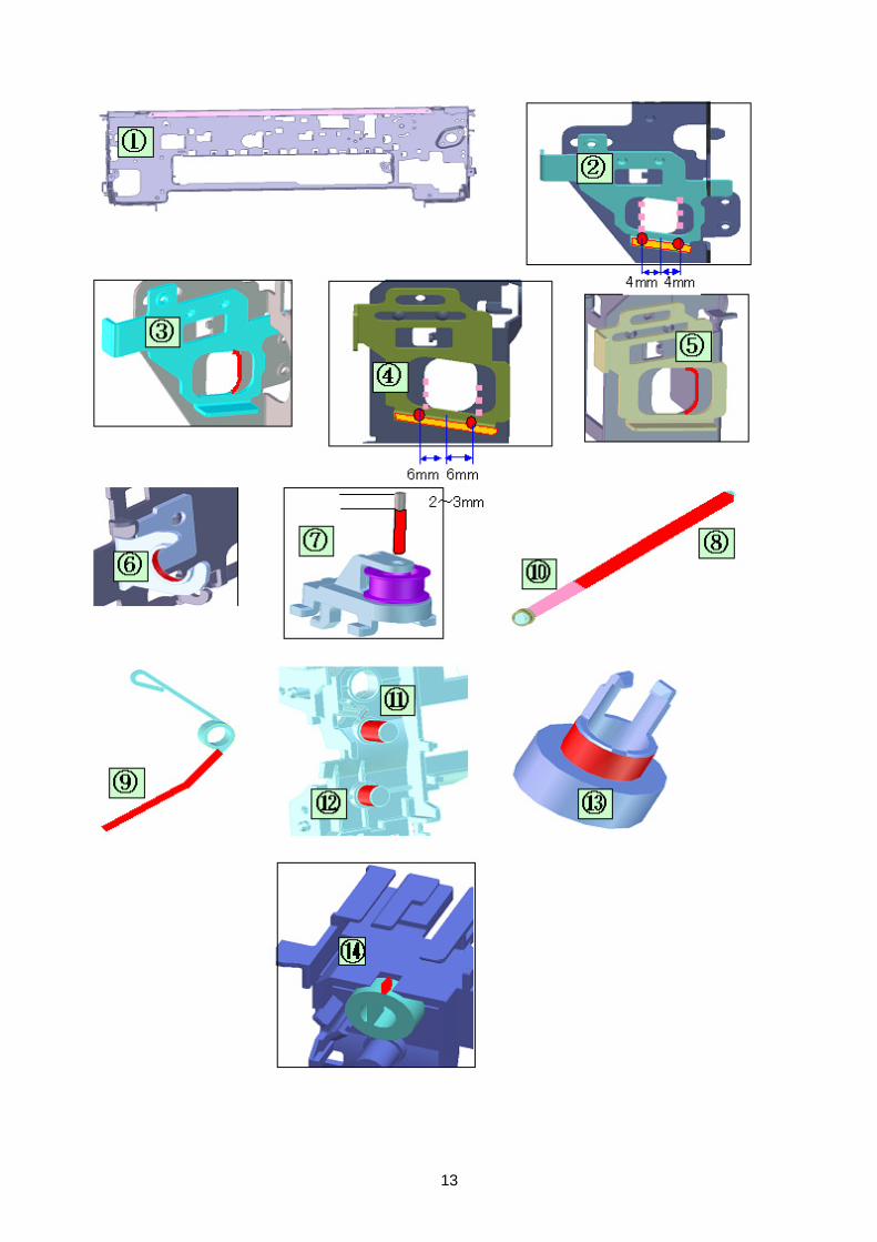
4-2. Grease Application (1) Printer Unit
No Part name Where to apply grease / oil Drawing
No. Grease / oil
Grease / oil amount (mg)
Number of drops* x locations
1 Chassis ass'y Entire surface the carriage slider contacts
(1) Floil KG107A 27 to 54 3 x 1
2 Adjust plate L Carriage shaft cam L sliding portion
(2) Floil KG107A 18 to 36 2 x 1
3 Chassis ass'y Carriage shaft sliding portion on the left side of the chassis (1 location)
(3) Floil KG107A 9 to 18 1 x 1
4 Adjust plate R Carriage shaft cam R sliding portion
(4) Floil KG107A 18 to 36 2 x 1
5 Chassis ass'y Carriage shaft sliding portion on the right side of the chassis (1 location)
(5) Floil KG107A 9 to 18 1 x 1
6 Chassis ass'y PR lift shaft cam contact portion (3 locations)
(6) Floil KG107A 18 to 27 1.5 x 3
7 Idler pulley The shaft surface which contacts the idler pulley hole
(7) Floil KG107A 9 to 18 1 x 1
8 Carriage shaft Entire surface of the carriage shaft where the carriage unit slides
(8) Floil KG107A 200 to 400
9 Carriage shaft spring L
Carriage shaft sliding portion (to the end of the spring)
(9) Floil KG107A 9 to 18 1 x 1
10 Carriage shaft
Carriage shaft surface where the carriage unit slides (and where the machine-application of the grease is not feasible)
(10) Floil KG107A 9 to 18 1 x 1
11 CL gear base Outer surface of the CL idle gear R cylinder
(11) Floil KG107A 9 to 18 1 x 1
12 CL gear base Outer surface of the CL output gear cylinder
(12) Floil KG107A 9 to 18 1 x 1
13 CL input gear Joint of the CL gear base (13) Floil KG107A 9 to 18 1 x 1 14 CL input gear CL input gear teeth (14) Floil KG107A 9 to 18 1 x 1
* 1 drop = 9 to 18 mg
13
14
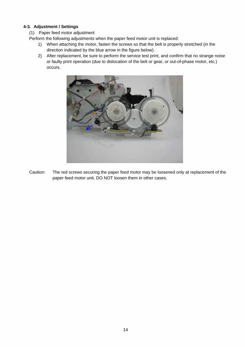
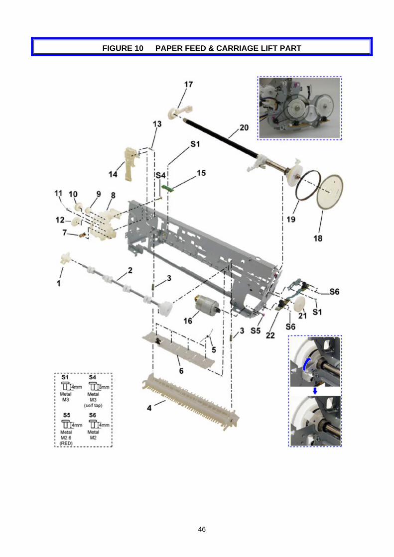
4-3. Adjustment / Settings (1) Paper feed motor adjustment Perform the following adjustments when the paper feed motor unit is replaced: 1) When attaching the motor, fasten the screws so that the belt is properly stretched (in the
direction indicated by the blue arrow in the figure below). 2) After replacement, be sure to perform the service test print, and confirm that no strange noise
or faulty print operation (due to dislocation of the belt or gear, or out-of-phase motor, etc.) occurs.
Caution: The red screws securing the paper feed motor may be loosened only at replacement of the paper feed motor unit. DO NOT loosen them in other cases.
15
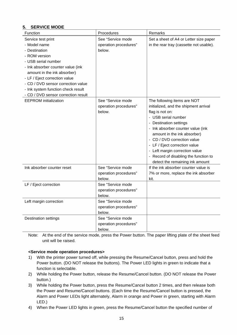
5. SERVICE MODE Function Procedures Remarks Service test print - Model name - Destination - ROM version - USB serial number - Ink absorber counter value (ink
amount in the ink absorber) - LF / Eject correction value - CD / DVD sensor correction value - Ink system function check result - CD / DVD sensor correction result
See “Service mode operation procedures” below.
Set a sheet of A4 or Letter size paper in the rear tray (cassette not usable).
EEPROM initialization See “Service mode operation procedures” below.
The following items are NOT initialized, and the shipment arrival flag is not on: - USB serial number - Destination settings - Ink absorber counter value (ink
amount in the ink absorber) - CD / DVD correction value - LF / Eject correction value - Left margin correction value - Record of disabling the function to
detect the remaining ink amount Ink absorber counter reset See “Service mode
operation procedures” below.
If the ink absorber counter value is 7% or more, replace the ink absorber kit.
LF / Eject correction See "Service mode operation procedures" below.
Left margin correction See "Service mode operation procedures" below.
Destination settings See "Service mode operation procedures" below.
Note: At the end of the service mode, press the Power button. The paper lifting plate of the sheet feed unit will be raised.
<Service mode operation procedures> 1) With the printer power turned off, while pressing the Resume/Cancel button, press and hold the
Power button. (DO NOT release the buttons). The Power LED lights in green to indicate that a function is selectable.
2) While holding the Power button, release the Resume/Cancel button. (DO NOT release the Power button.)
3) While holding the Power button, press the Resume/Cancel button 2 times, and then release both the Power and Resume/Cancel buttons. (Each time the Resume/Cancel button is pressed, the Alarm and Power LEDs light alternately, Alarm in orange and Power in green, starting with Alarm LED.)
4) When the Power LED lights in green, press the Resume/Cancel button the specified number of
16
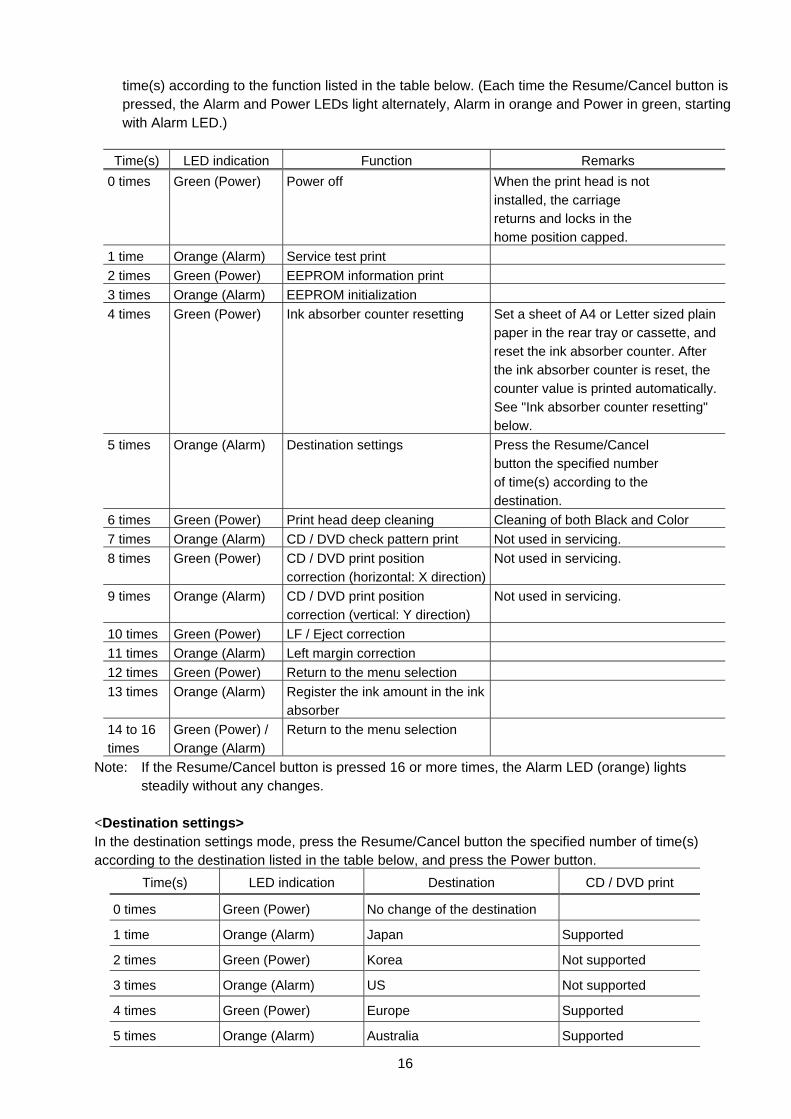
time(s) according to the function listed in the table below. (Each time the Resume/Cancel button is pressed, the Alarm and Power LEDs light alternately, Alarm in orange and Power in green, starting with Alarm LED.)
Time(s) LED indication Function Remarks
0 times Green (Power) Power off When the print head is not installed, the carriage returns and locks in the home position capped.
1 time Orange (Alarm) Service test print 2 times Green (Power) EEPROM information print 3 times Orange (Alarm) EEPROM initialization 4 times Green (Power) Ink absorber counter resetting Set a sheet of A4 or Letter sized plain
paper in the rear tray or cassette, and reset the ink absorber counter. After the ink absorber counter is reset, the counter value is printed automatically. See "Ink absorber counter resetting" below.
5 times Orange (Alarm) Destination settings Press the Resume/Cancel button the specified number of time(s) according to the destination.
6 times Green (Power) Print head deep cleaning Cleaning of both Black and Color 7 times Orange (Alarm) CD / DVD check pattern print Not used in servicing. 8 times Green (Power) CD / DVD print position
correction (horizontal: X direction)Not used in servicing.
9 times Orange (Alarm) CD / DVD print position correction (vertical: Y direction)
Not used in servicing.
10 times Green (Power) LF / Eject correction 11 times Orange (Alarm) Left margin correction 12 times Green (Power) Return to the menu selection 13 times Orange (Alarm) Register the ink amount in the ink
absorber
14 to 16 times
Green (Power) / Orange (Alarm)
Return to the menu selection
Note: If the Resume/Cancel button is pressed 16 or more times, the Alarm LED (orange) lights steadily without any changes.
<Destination settings> In the destination settings mode, press the Resume/Cancel button the specified number of time(s) according to the destination listed in the table below, and press the Power button.
Time(s) LED indication Destination CD / DVD print
0 times Green (Power) No change of the destination
1 time Orange (Alarm) Japan Supported
2 times Green (Power) Korea Not supported
3 times Orange (Alarm) US Not supported
4 times Green (Power) Europe Supported
5 times Orange (Alarm) Australia Supported
17
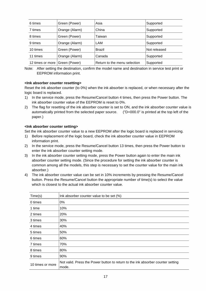
6 times Green (Power) Asia Supported
7 times Orange (Alarm) China Supported
8 times Green (Power) Taiwan Supported
9 times Orange (Alarm) LAM Supported
10 times Green (Power) Brazil Not released
11 times Orange (Alarm) Canada Supported
12 times or more Green (Power) Return to the menu selection Supported
Note: After setting the destination, confirm the model name and destination in service test print or EEPROM information print.
<Ink absorber counter resetting> Reset the ink absorber counter (to 0%) when the ink absorber is replaced, or when necessary after the logic board is replaced. 1) In the service mode, press the Resume/Cancel button 4 times, then press the Power button. The
ink absorber counter value of the EEPROM is reset to 0%. 2) The flag for resetting of the ink absorber counter is set to ON, and the ink absorber counter value is
automatically printed from the selected paper source. ("D=000.0" is printed at the top left of the paper.)
<Ink absorber counter setting> Set the ink absorber counter value to a new EEPROM after the logic board is replaced in servicing. 1) Before replacement of the logic board, check the ink absorber counter value in EEPROM
information print. 2) In the service mode, press the Resume/Cancel button 13 times, then press the Power button to
enter the ink absorber counter setting mode. 3) In the ink absorber counter setting mode, press the Power button again to enter the main ink
absorber counter setting mode. (Since the procedure for setting the ink absorber counter is common among all the models, this step is necessary to set the counter value for the main ink absorber.)
4) The ink absorber counter value can be set in 10% increments by pressing the Resume/Cancel button. Press the Resume/Cancel button the appropriate number of time(s) to select the value which is closest to the actual ink absorber counter value.
Time(s) Ink absorber counter value to be set (%)
0 times 0%
1 time 10%
2 times 20%
3 times 30%
4 times 40%
5 times 50%
6 times 60%
7 times 70%
8 times 80%
9 times 90%
10 times or more Not valid. Press the Power button to return to the ink absorber counter setting mode.
18
5) Press the Power button to set the selected value to the EEPROM. Print EEPROM information to
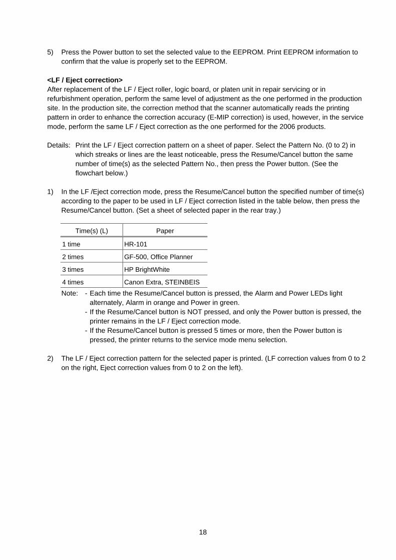
confirm that the value is properly set to the EEPROM. <LF / Eject correction> After replacement of the LF / Eject roller, logic board, or platen unit in repair servicing or in refurbishment operation, perform the same level of adjustment as the one performed in the production site. In the production site, the correction method that the scanner automatically reads the printing pattern in order to enhance the correction accuracy (E-MIP correction) is used, however, in the service mode, perform the same LF / Eject correction as the one performed for the 2006 products. Details: Print the LF / Eject correction pattern on a sheet of paper. Select the Pattern No. (0 to 2) in
which streaks or lines are the least noticeable, press the Resume/Cancel button the same number of time(s) as the selected Pattern No., then press the Power button. (See the flowchart below.)
1) In the LF /Eject correction mode, press the Resume/Cancel button the specified number of time(s)
according to the paper to be used in LF / Eject correction listed in the table below, then press the Resume/Cancel button. (Set a sheet of selected paper in the rear tray.)
Time(s) (L) Paper
1 time HR-101
2 times GF-500, Office Planner
3 times HP BrightWhite
4 times Canon Extra, STEINBEIS
Note: - Each time the Resume/Cancel button is pressed, the Alarm and Power LEDs light alternately, Alarm in orange and Power in green.
- If the Resume/Cancel button is NOT pressed, and only the Power button is pressed, the printer remains in the LF / Eject correction mode.
- If the Resume/Cancel button is pressed 5 times or more, then the Power button is pressed, the printer returns to the service mode menu selection.
2) The LF / Eject correction pattern for the selected paper is printed. (LF correction values from 0 to 2
on the right, Eject correction values from 0 to 2 on the left).
19
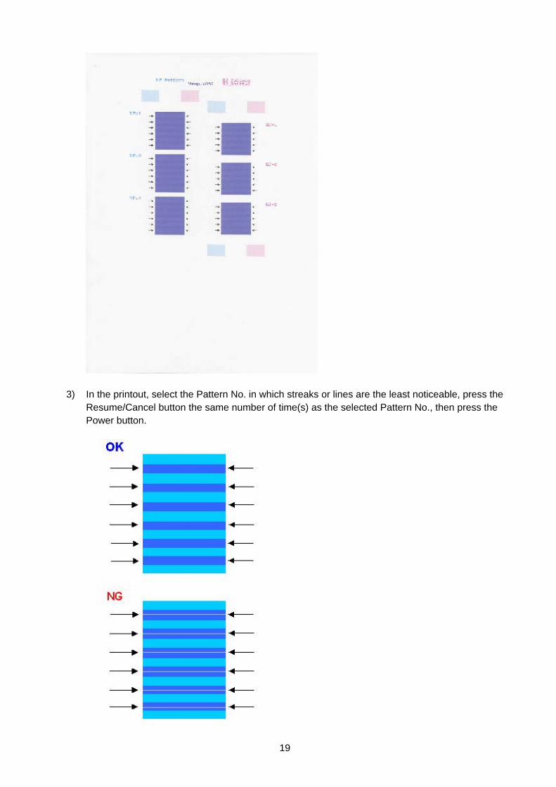
3) In the printout, select the Pattern No. in which streaks or lines are the least noticeable, press the
Resume/Cancel button the same number of time(s) as the selected Pattern No., then press the Power button.
20
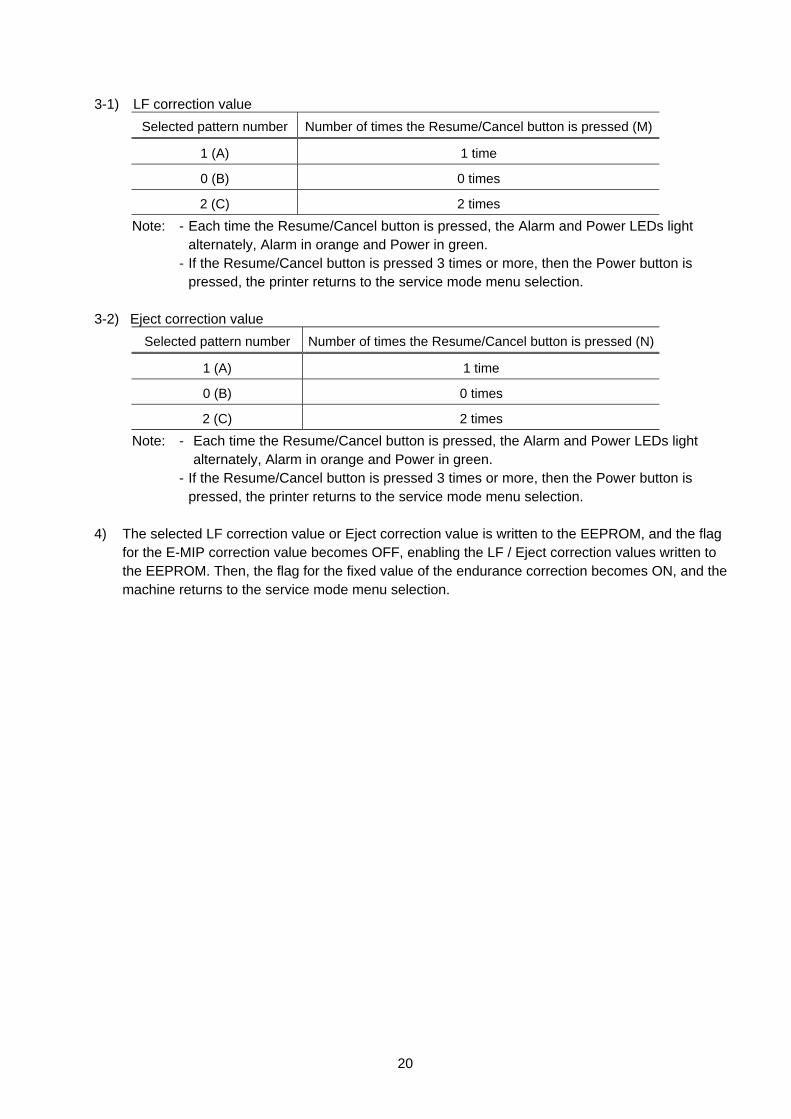
3-1) LF correction value
Selected pattern number Number of times the Resume/Cancel button is pressed (M)
1 (A) 1 time
0 (B) 0 times
2 (C) 2 times
Note: - Each time the Resume/Cancel button is pressed, the Alarm and Power LEDs light alternately, Alarm in orange and Power in green.
- If the Resume/Cancel button is pressed 3 times or more, then the Power button is pressed, the printer returns to the service mode menu selection.
3-2) Eject correction value
Selected pattern number Number of times the Resume/Cancel button is pressed (N)
1 (A) 1 time
0 (B) 0 times
2 (C) 2 times
Note: - Each time the Resume/Cancel button is pressed, the Alarm and Power LEDs light alternately, Alarm in orange and Power in green.
- If the Resume/Cancel button is pressed 3 times or more, then the Power button is pressed, the printer returns to the service mode menu selection.
4) The selected LF correction value or Eject correction value is written to the EEPROM, and the flag
for the E-MIP correction value becomes OFF, enabling the LF / Eject correction values written to the EEPROM. Then, the flag for the fixed value of the endurance correction becomes ON, and the machine returns to the service mode menu selection.
21
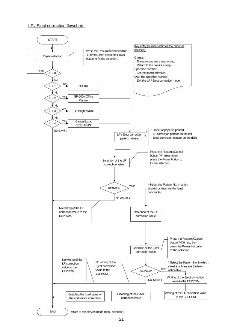
LF / Eject correction flowchart:
START
Key entry (number of times the button ispressed):
0 times: The previous entry was wrong. Return to the previous step.Specified number: Set the specified value.Over the specified number: Exit the LF / Eject correction mode.
L = 0
Paper selection
Press the Resume/Cancel button"L" times, then press the Powerbutton to fix the selection.
L = 1
L = 2
L = 3
L = 4
Yes
No
NoYes
Yes
Yes
Yes
No
No
No(L>=5)
HR-101
GF-500 / OfficePlanner
HP Bright White
Canon Extra,STEINBEIS
LF / Eject correctionpattern printing
1 sheet of paper is printed.- LF correction pattern on the left- Eject correction pattern on the right
Selection of the LFcorrection value
Press the Resume/Cancelbutton "M" times, thenpress the Power button tofix the selection.
0=<M=<2
Retention of the LFcorrection value
END
Yes*
No(M>=3)
Selection of the Ejectcorrection value
0=<N=<2
Writing of the Eject correctionvalue to the EEPROMNo(N>=3)
Press the Resume/Cancelbutton "N" times, thenpress the Power button tofix the selection.
Yes*
No writing of the LFcorrection value to theEEPROM.
No writing of theEject correctionvalue to theEEPROM
* Select the Pattern No. in whichstreaks or lines are the leastnoticeable.
* Select the Pattern No. in whichstreaks or lines are the leastnoticeable.
Return to the service mode menu selection.
No writing of theLF correctionvalue to theEEPROM
Writing of the LF correction valueto the EEPROM
Disabling of the E-MIPcorrection value
Enabling the fixed value ofthe endurance correction
22
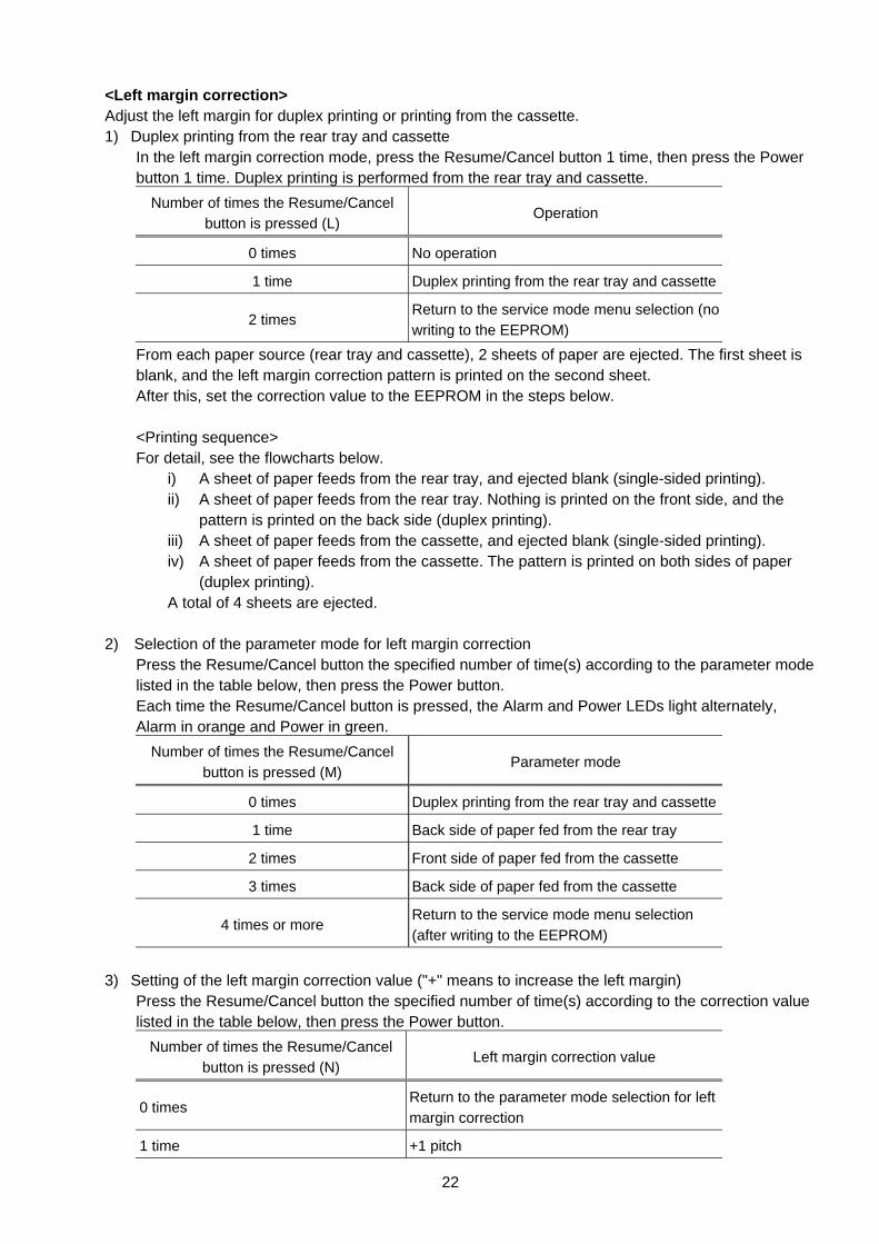
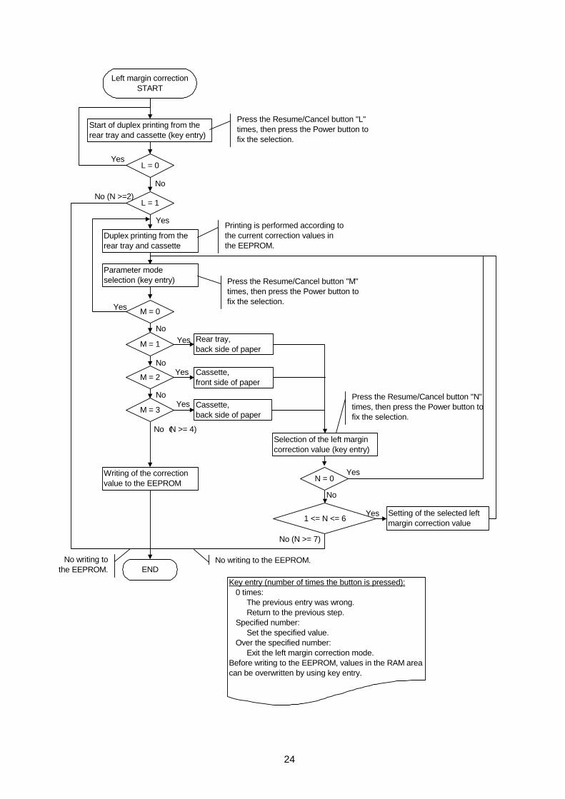
<Left margin correction> Adjust the left margin for duplex printing or printing from the cassette. 1) Duplex printing from the rear tray and cassette In the left margin correction mode, press the Resume/Cancel button 1 time, then press the Power
button 1 time. Duplex printing is performed from the rear tray and cassette. Number of times the Resume/Cancel
button is pressed (L) Operation
0 times No operation
1 time Duplex printing from the rear tray and cassette
2 times Return to the service mode menu selection (no writing to the EEPROM)
From each paper source (rear tray and cassette), 2 sheets of paper are ejected. The first sheet is blank, and the left margin correction pattern is printed on the second sheet.
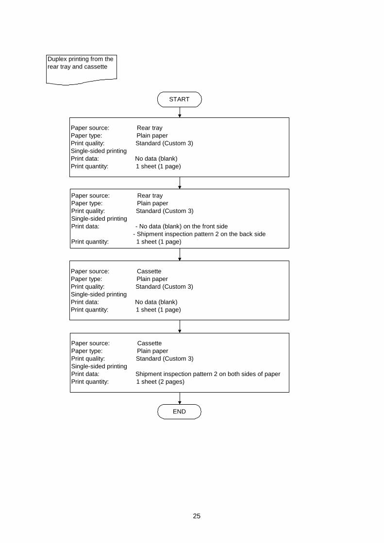
After this, set the correction value to the EEPROM in the steps below. <Printing sequence> For detail, see the flowcharts below. i) A sheet of paper feeds from the rear tray, and ejected blank (single-sided printing). ii) A sheet of paper feeds from the rear tray. Nothing is printed on the front side, and the
pattern is printed on the back side (duplex printing). iii) A sheet of paper feeds from the cassette, and ejected blank (single-sided printing). iv) A sheet of paper feeds from the cassette. The pattern is printed on both sides of paper
(duplex printing). A total of 4 sheets are ejected. 2) Selection of the parameter mode for left margin correction Press the Resume/Cancel button the specified number of time(s) according to the parameter mode
listed in the table below, then press the Power button. Each time the Resume/Cancel button is pressed, the Alarm and Power LEDs light alternately,
Alarm in orange and Power in green. Number of times the Resume/Cancel
button is pressed (M) Parameter mode
0 times Duplex printing from the rear tray and cassette
1 time Back side of paper fed from the rear tray
2 times Front side of paper fed from the cassette
3 times Back side of paper fed from the cassette
4 times or more Return to the service mode menu selection (after writing to the EEPROM)
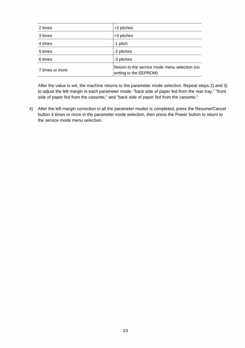
3) Setting of the left margin correction value ("+" means to increase the left margin) Press the Resume/Cancel button the specified number of time(s) according to the correction value
listed in the table below, then press the Power button. Number of times the Resume/Cancel
button is pressed (N) Left margin correction value
0 times Return to the parameter mode selection for left margin correction
1 time +1 pitch
23
2 times +2 pitches
3 times +3 pitches
4 times -1 pitch
5 times -2 pitches
6 times -3 pitches
7 times or more Return to the service mode menu selection (no writing to the EEPROM)
After the value is set, the machine returns to the parameter mode selection. Repeat steps 2) and 3)
to adjust the left margin in each parameter mode: "back side of paper fed from the rear tray," "front side of paper fed from the cassette," and "back side of paper fed from the cassette."
4) After the left margin correction in all the parameter modes is completed, press the Resume/Cancel
button 4 times or more in the parameter mode selection, then press the Power button to return to the service mode menu selection.
24
Press the Resume/Cancel button "N"times, then press the Power button tofix the selection.
Left margin correctionSTART
L = 0
Start of duplex printing from therear tray and cassette (key entry)
M = 0
M = 1
M = 2
M = 3
Yes
No
NoYes
Yes
Yes
No
No
No (N >= 4)
Rear tray,back side of paper
Cassette,front side of paper
Cassette,back side of paper
Selection of the left margincorrection value (key entry)
1 <= N <= 6
END
Yes
No (N >= 7)
L = 1
Yes
No (N >=2)
Duplex printing from therear tray and cassette
Parameter modeselection (key entry)
Printing is performed according tothe current correction values inthe EEPROM.
Press the Resume/Cancel button "L"times, then press the Power button tofix the selection.
Press the Resume/Cancel button "M"times, then press the Power button tofix the selection.
Yes
N = 0
No
Yes
Setting of the selected leftmargin correction value
Writing of the correctionvalue to the EEPROM
No writing to the EEPROM.No writing tothe EEPROM.
Key entry (number of times the button is pressed): 0 times: The previous entry was wrong. Return to the previous step. Specified number: Set the specified value. Over the specified number: Exit the left margin correction mode.Before writing to the EEPROM, values in the RAM areacan be overwritten by using key entry.
25
START
Paper source: Rear trayPaper type: Plain paperPrint quality: Standard (Custom 3)Single-sided printingPrint data: No data (blank)Print quantity: 1 sheet (1 page)
END
Duplex printing from therear tray and cassette
Paper source: Rear trayPaper type: Plain paperPrint quality: Standard (Custom 3)Single-sided printingPrint data: - No data (blank) on the front side - Shipment inspection pattern 2 on the back sidePrint quantity: 1 sheet (1 page)
Paper source: CassettePaper type: Plain paperPrint quality: Standard (Custom 3)Single-sided printingPrint data: No data (blank)Print quantity: 1 sheet (1 page)
Paper source: CassettePaper type: Plain paperPrint quality: Standard (Custom 3)Single-sided printingPrint data: Shipment inspection pattern 2 on both sides of paperPrint quantity: 1 sheet (2 pages)
26
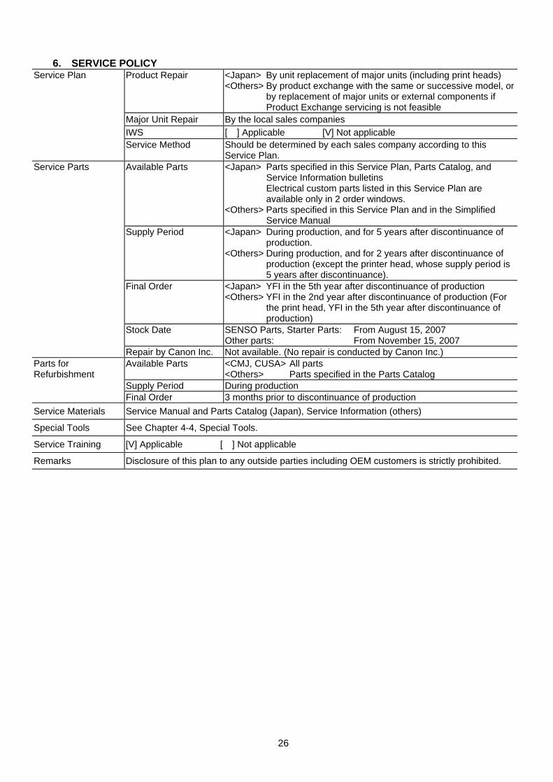
6. SERVICE POLICY Product Repair <Japan> By unit replacement of major units (including print heads)
<Others> By product exchange with the same or successive model, or by replacement of major units or external components if Product Exchange servicing is not feasible
Major Unit Repair By the local sales companies IWS [ ] Applicable [V] Not applicable
Service Plan
Service Method Should be determined by each sales company according to this Service Plan.
Available Parts <Japan> Parts specified in this Service Plan, Parts Catalog, and Service Information bulletins
Electrical custom parts listed in this Service Plan are available only in 2 order windows.
<Others> Parts specified in this Service Plan and in the Simplified Service Manual
Supply Period <Japan> During production, and for 5 years after discontinuance of production.
<Others> During production, and for 2 years after discontinuance of production (except the printer head, whose supply period is 5 years after discontinuance).
Final Order <Japan> YFI in the 5th year after discontinuance of production <Others> YFI in the 2nd year after discontinuance of production (For
the print head, YFI in the 5th year after discontinuance of production)
Stock Date SENSO Parts, Starter Parts: From August 15, 2007 Other parts: From November 15, 2007
Service Parts
Repair by Canon Inc. Not available. (No repair is conducted by Canon Inc.) Available Parts <CMJ, CUSA> All parts
<Others> Parts specified in the Parts Catalog Supply Period During production
Parts for Refurbishment
Final Order 3 months prior to discontinuance of production Service Materials Service Manual and Parts Catalog (Japan), Service Information (others)
Special Tools See Chapter 4-4, Special Tools.
Service Training [V] Applicable [ ] Not applicable
Remarks Disclosure of this plan to any outside parties including OEM customers is strictly prohibited.

27
This page intentionally left blank
28
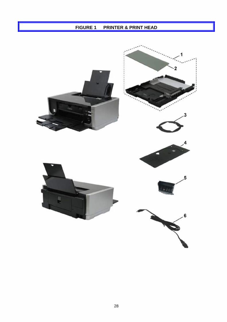
FIGURE 1 PRINTER & PRINT HEAD
29
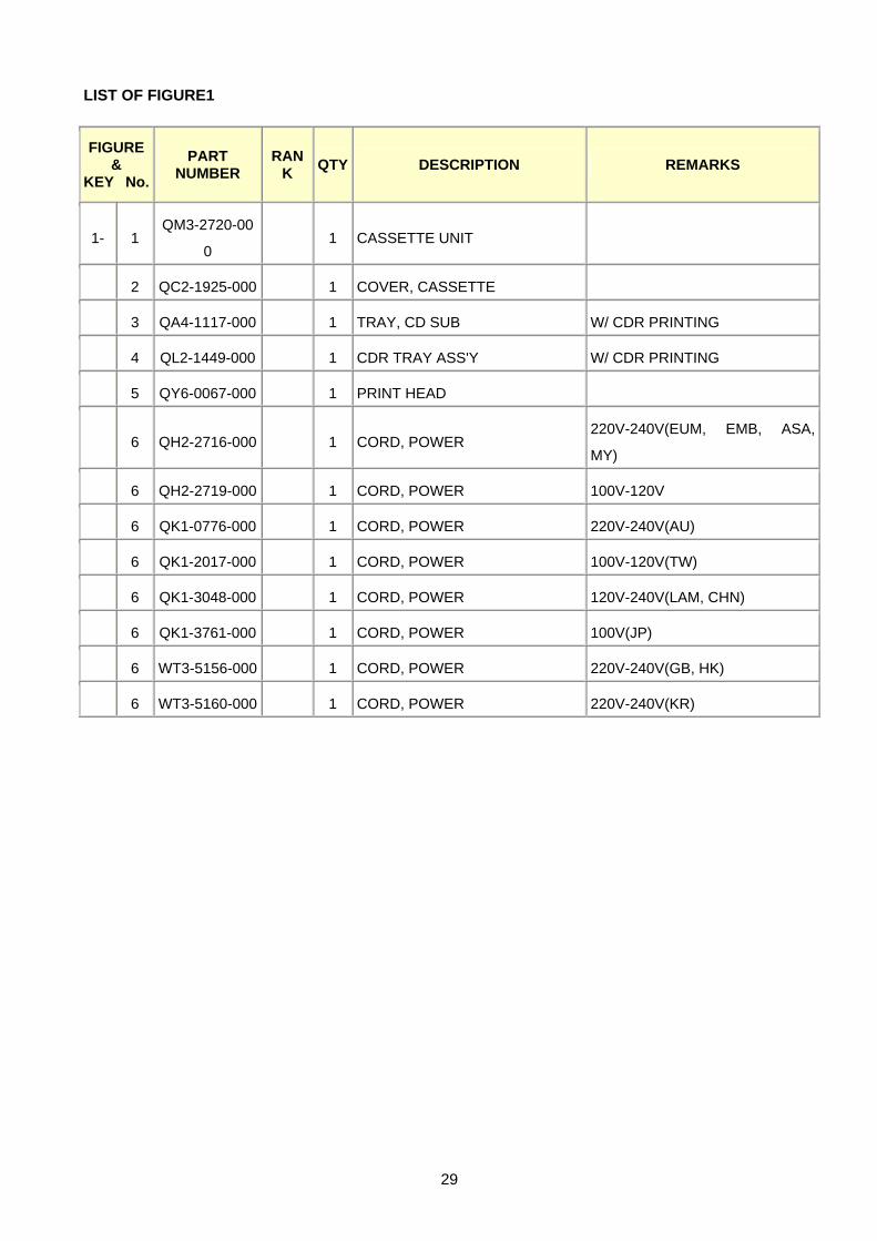
LIST OF FIGURE1
FIGURE &
KEY No.
PART NUMBER
RANK QTY DESCRIPTION REMARKS
1- 1 QM3-2720-00
0 1 CASSETTE UNIT
2 QC2-1925-000 1 COVER, CASSETTE
3 QA4-1117-000 1 TRAY, CD SUB W/ CDR PRINTING
4 QL2-1449-000 1 CDR TRAY ASS'Y W/ CDR PRINTING
5 QY6-0067-000 1 PRINT HEAD
6 QH2-2716-000 1 CORD, POWER 220V-240V(EUM, EMB, ASA,
MY)
6 QH2-2719-000 1 CORD, POWER 100V-120V
6 QK1-0776-000 1 CORD, POWER 220V-240V(AU)
6 QK1-2017-000 1 CORD, POWER 100V-120V(TW)
6 QK1-3048-000 1 CORD, POWER 120V-240V(LAM, CHN)
6 QK1-3761-000 1 CORD, POWER 100V(JP)
6 WT3-5156-000 1 CORD, POWER 220V-240V(GB, HK)
6 WT3-5160-000 1 CORD, POWER 220V-240V(KR)
30
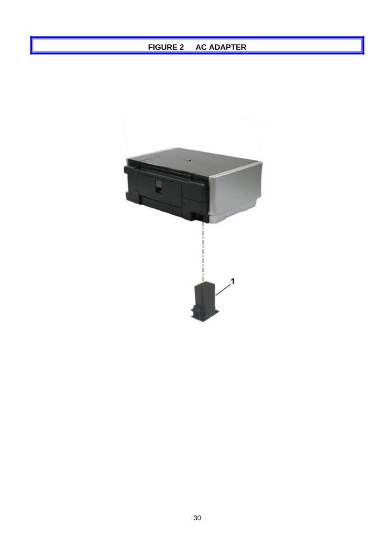
FIGURE 2 AC ADAPTER

31
LIST OF FIGURE2
FIGURE & KEY No.
PART NUMBER
RANK QTY DESCRIPTION REMARKS
2- 1 QK1-3691-000 1 AC ADAPTER: 100V-240V 50/60HZ
32
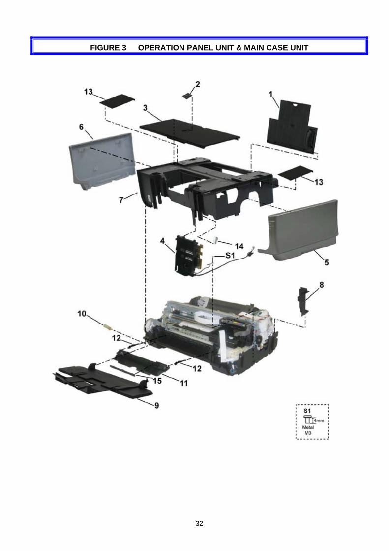
FIGURE 3 OPERATION PANEL UNIT & MAIN CASE UNIT
33
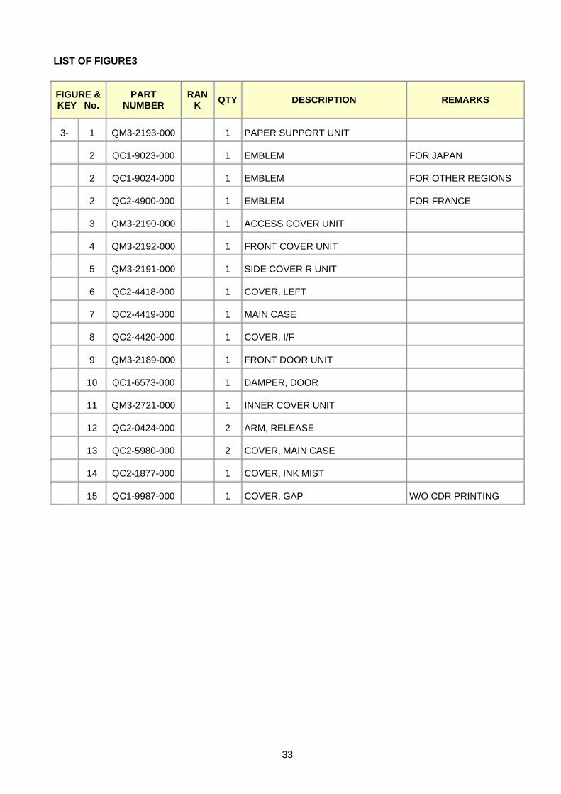
LIST OF FIGURE3
FIGURE & KEY No.
PART NUMBER
RANK QTY DESCRIPTION REMARKS
3- 1 QM3-2193-000 1 PAPER SUPPORT UNIT
2 QC1-9023-000 1 EMBLEM FOR JAPAN
2 QC1-9024-000 1 EMBLEM FOR OTHER REGIONS
2 QC2-4900-000 1 EMBLEM FOR FRANCE
3 QM3-2190-000 1 ACCESS COVER UNIT
4 QM3-2192-000 1 FRONT COVER UNIT
5 QM3-2191-000 1 SIDE COVER R UNIT
6 QC2-4418-000 1 COVER, LEFT
7 QC2-4419-000 1 MAIN CASE
8 QC2-4420-000 1 COVER, I/F
9 QM3-2189-000 1 FRONT DOOR UNIT
10 QC1-6573-000 1 DAMPER, DOOR
11 QM3-2721-000 1 INNER COVER UNIT
12 QC2-0424-000 2 ARM, RELEASE
13 QC2-5980-000 2 COVER, MAIN CASE
14 QC2-1877-000 1 COVER, INK MIST
15 QC1-9987-000 1 COVER, GAP W/O CDR PRINTING
34
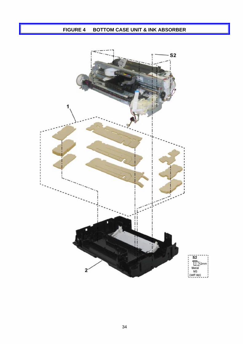
FIGURE 4 BOTTOM CASE UNIT & INK ABSORBER

35
LIST OF FIGURE4
FIGURE & KEY No.
PART NUMBER
RANK QTY DESCRIPTION REMARKS
4- 1 QY5-0190-000 1 ABSORBER KIT
2 QM3-2718-000 1 BOTTOM CASE UNIT
36
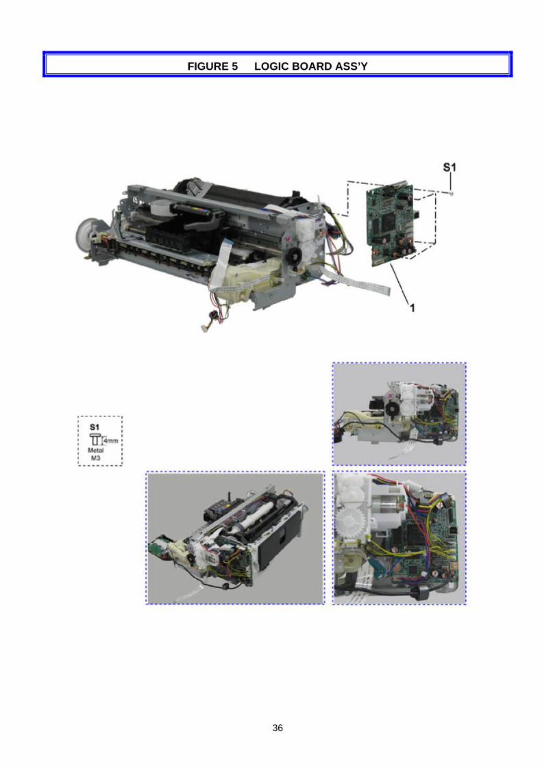
FIGURE 5 LOGIC BOARD ASS’Y

37
LIST OF FIGURE5
FIGURE & KEY No.
PART NUMBER
RANK QTY DESCRIPTION REMARKS
5- 1 QM3-2738-000 1 LOGIC BOARD ASS'Y
38
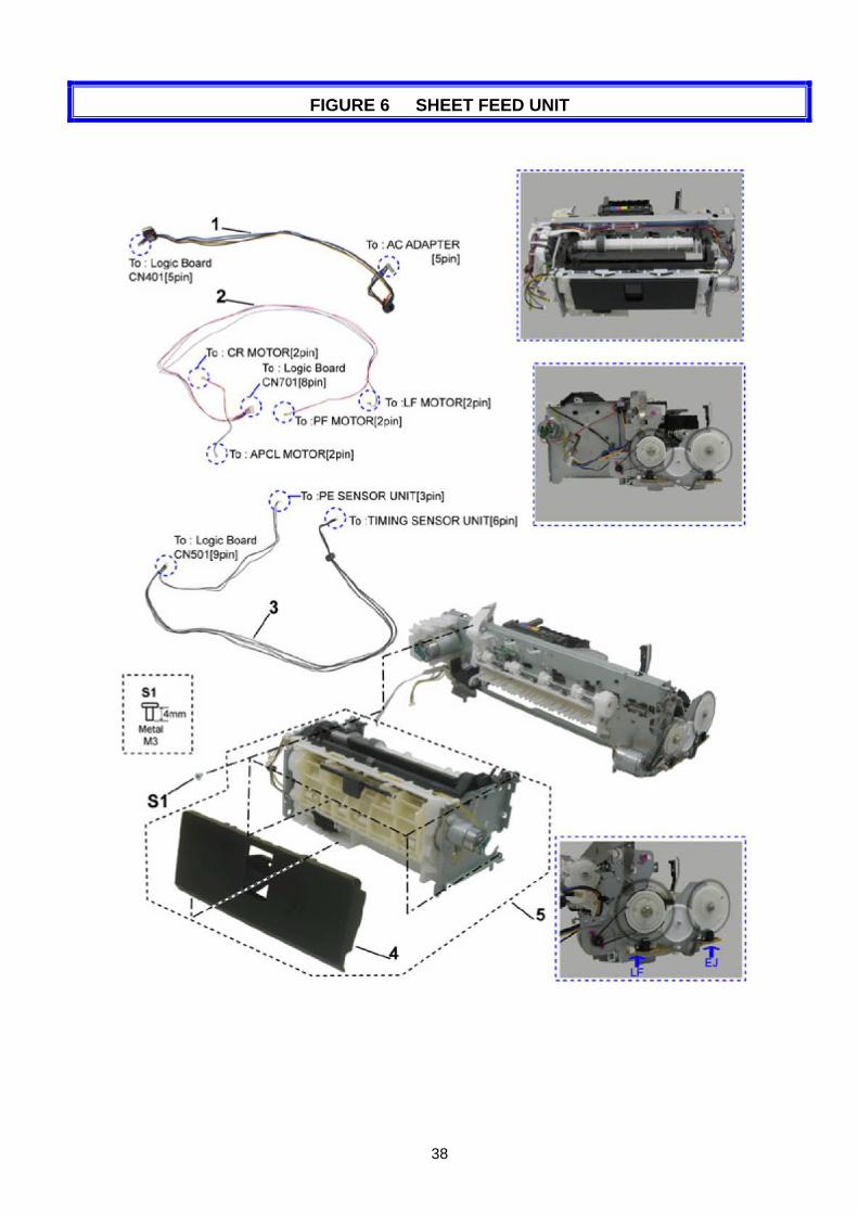
FIGURE 6 SHEET FEED UNIT
39
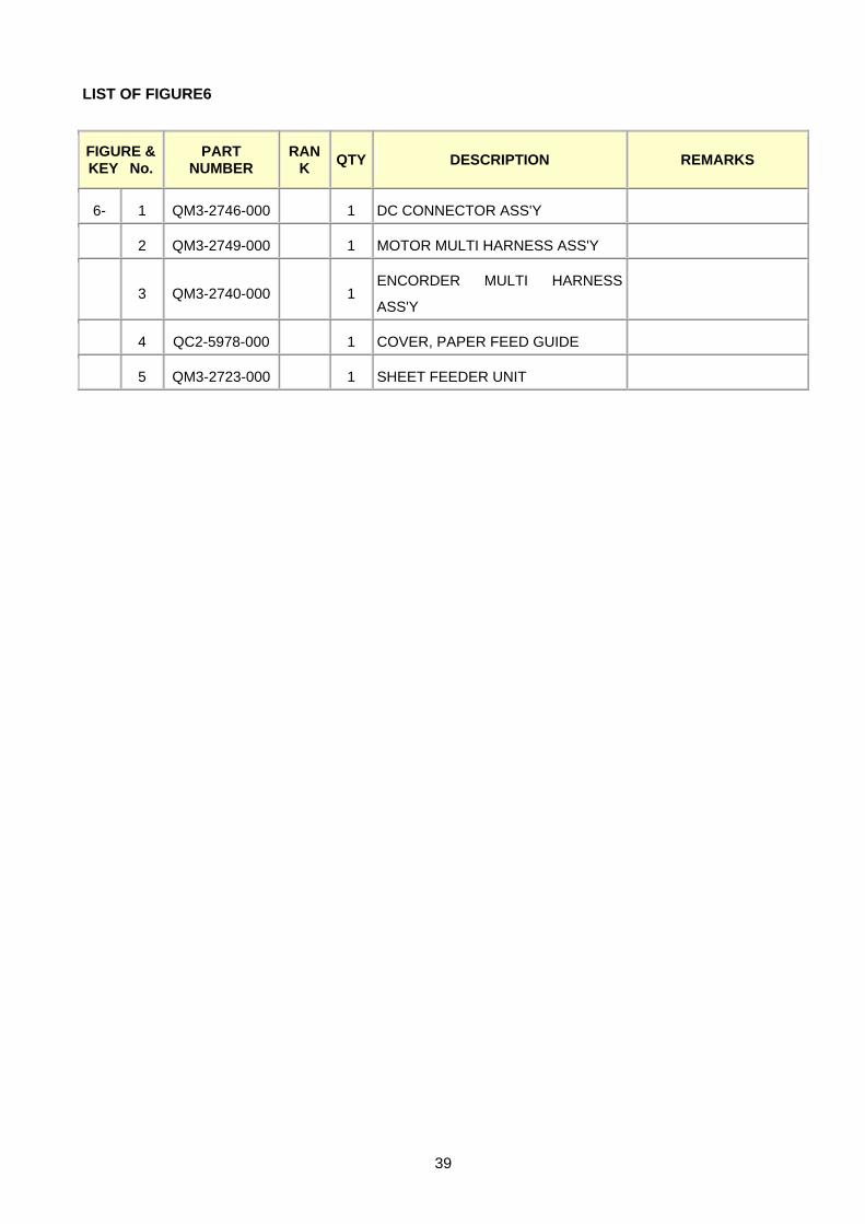
LIST OF FIGURE6
FIGURE & KEY No.
PART NUMBER
RANK QTY DESCRIPTION REMARKS
6- 1 QM3-2746-000 1 DC CONNECTOR ASS'Y
2 QM3-2749-000 1 MOTOR MULTI HARNESS ASS'Y
3 QM3-2740-000 1 ENCORDER MULTI HARNESS
ASS'Y
4 QC2-5978-000 1 COVER, PAPER FEED GUIDE
5 QM3-2723-000 1 SHEET FEEDER UNIT
40
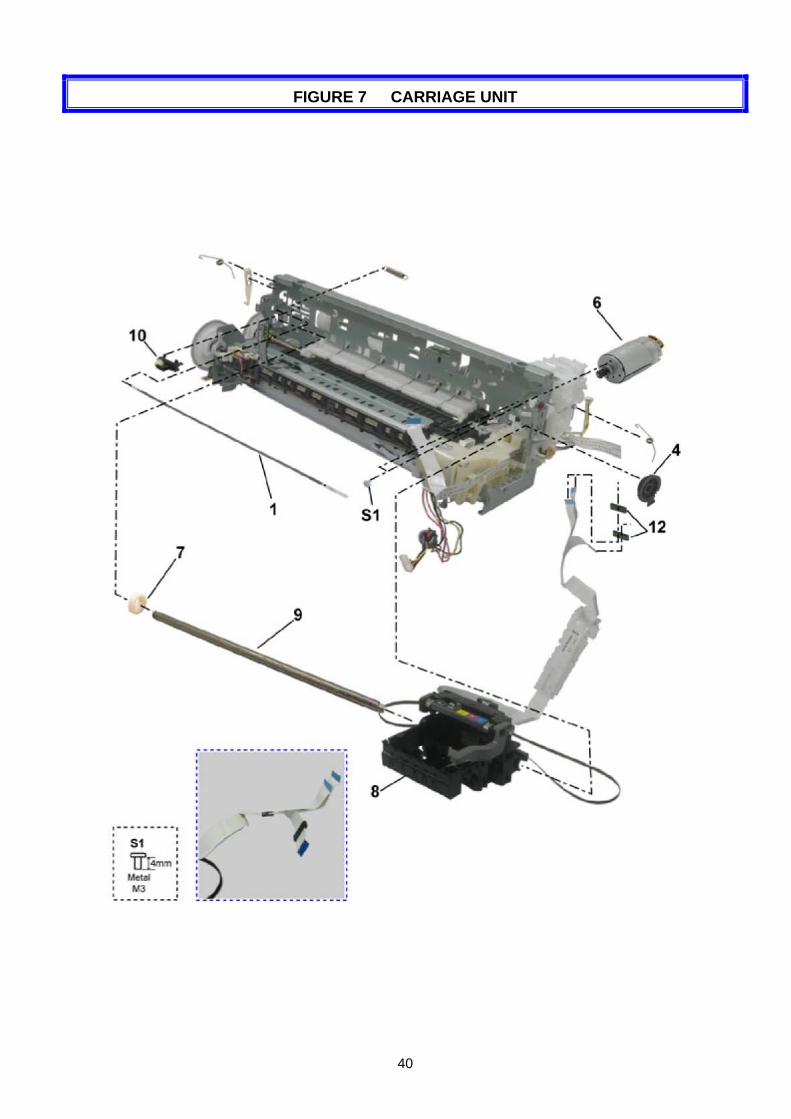
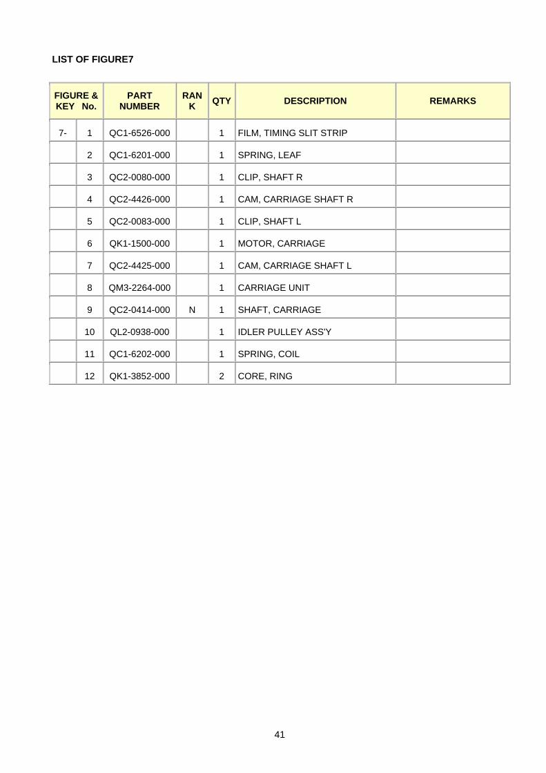
FIGURE 7 CARRIAGE UNIT
41
LIST OF FIGURE7
FIGURE & KEY No.
PART NUMBER
RANK QTY DESCRIPTION REMARKS
7- 1 QC1-6526-000 1 FILM, TIMING SLIT STRIP
2 QC1-6201-000 1 SPRING, LEAF
3 QC2-0080-000 1 CLIP, SHAFT R
4 QC2-4426-000 1 CAM, CARRIAGE SHAFT R
5 QC2-0083-000 1 CLIP, SHAFT L
6 QK1-1500-000 1 MOTOR, CARRIAGE
7 QC2-4425-000 1 CAM, CARRIAGE SHAFT L
8 QM3-2264-000 1 CARRIAGE UNIT
9 QC2-0414-000 N 1 SHAFT, CARRIAGE
10 QL2-0938-000 1 IDLER PULLEY ASS'Y
11 QC1-6202-000 1 SPRING, COIL
12 QK1-3852-000 2 CORE, RING
42
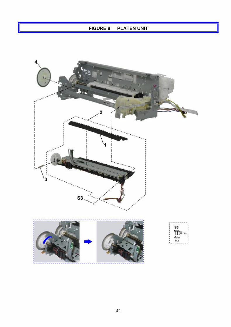
FIGURE 8 PLATEN UNIT

43
LIST OF FIGURE8
FIGURE & KEY No.
PART NUMBER
RANK QTY DESCRIPTION REMARKS
8- 1 QC2-4888-000 1 ABSORBER, INK
2 QM3-2725-000 1 PLATEN UNIT
3 QC1-6619-000 1 SPRING, TENSION
4 QC2-4881-000 1 FILM, TIMING SLIT DISK EJECT
44
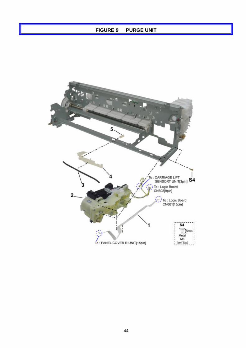
FIGURE 9 PURGE UNIT
45
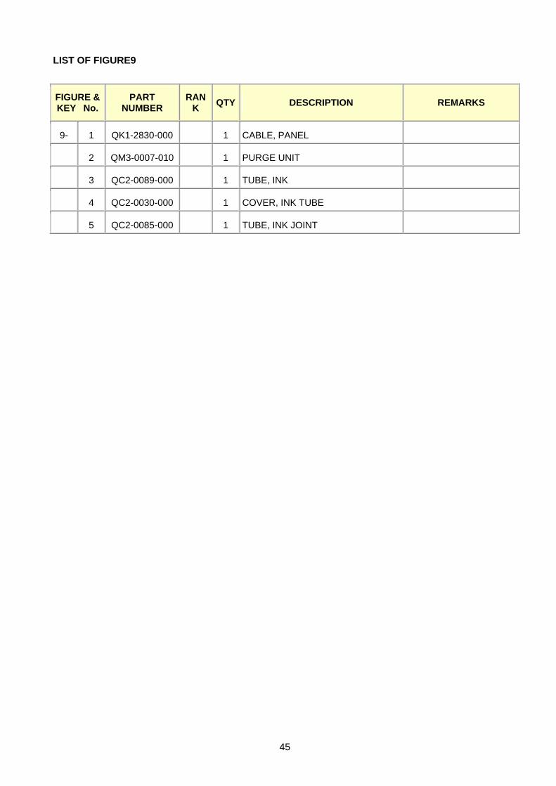
LIST OF FIGURE9
FIGURE & KEY No.
PART NUMBER
RANK QTY DESCRIPTION REMARKS
9- 1 QK1-2830-000 1 CABLE, PANEL
2 QM3-0007-010 1 PURGE UNIT
3 QC2-0089-000 1 TUBE, INK
4 QC2-0030-000 1 COVER, INK TUBE
5 QC2-0085-000 1 TUBE, INK JOINT
46
FIGURE 10 PAPER FEED & CARRIAGE LIFT PART
47
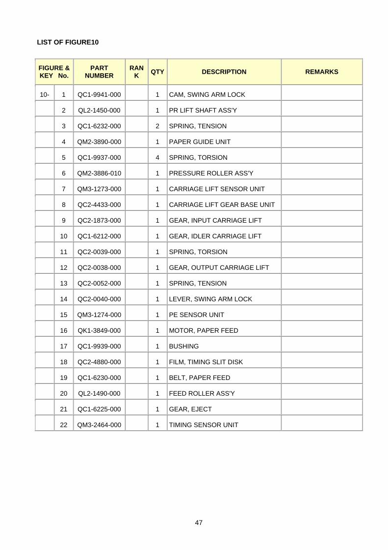
LIST OF FIGURE10
FIGURE & KEY No.
PART NUMBER
RANK QTY DESCRIPTION REMARKS
10- 1 QC1-9941-000 1 CAM, SWING ARM LOCK
2 QL2-1450-000 1 PR LIFT SHAFT ASS'Y
3 QC1-6232-000 2 SPRING, TENSION
4 QM2-3890-000 1 PAPER GUIDE UNIT
5 QC1-9937-000 4 SPRING, TORSION
6 QM2-3886-010 1 PRESSURE ROLLER ASS'Y
7 QM3-1273-000 1 CARRIAGE LIFT SENSOR UNIT
8 QC2-4433-000 1 CARRIAGE LIFT GEAR BASE UNIT
9 QC2-1873-000 1 GEAR, INPUT CARRIAGE LIFT
10 QC1-6212-000 1 GEAR, IDLER CARRIAGE LIFT
11 QC2-0039-000 1 SPRING, TORSION
12 QC2-0038-000 1 GEAR, OUTPUT CARRIAGE LIFT
13 QC2-0052-000 1 SPRING, TENSION
14 QC2-0040-000 1 LEVER, SWING ARM LOCK
15 QM3-1274-000 1 PE SENSOR UNIT
16 QK1-3849-000 1 MOTOR, PAPER FEED
17 QC1-9939-000 1 BUSHING
18 QC2-4880-000 1 FILM, TIMING SLIT DISK
19 QC1-6230-000 1 BELT, PAPER FEED
20 QL2-1490-000 1 FEED ROLLER ASS'Y
21 QC1-6225-000 1 GEAR, EJECT
22 QM3-2464-000 1 TIMING SENSOR UNIT
48
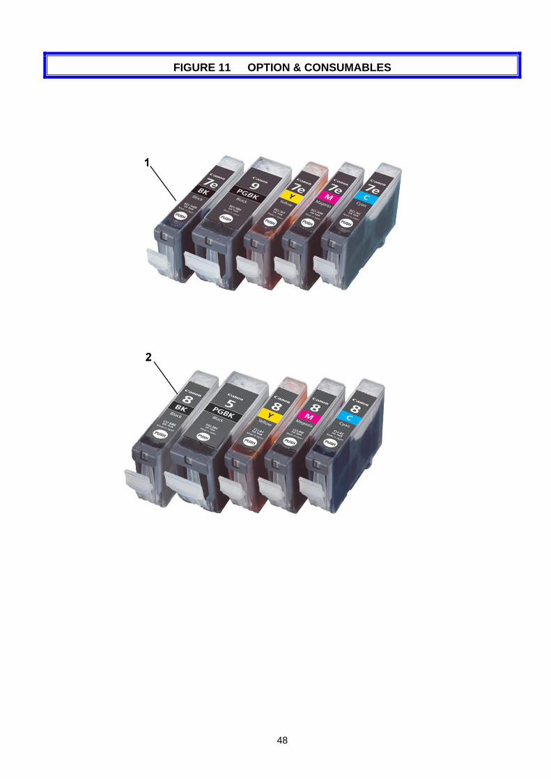
FIGURE 11 OPTION & CONSUMABLES
49
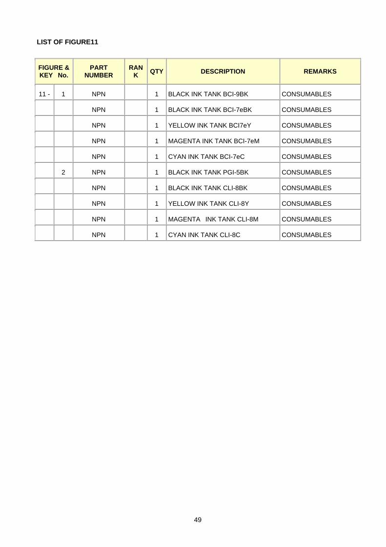
LIST OF FIGURE11
FIGURE & KEY No.
PART NUMBER
RANK QTY DESCRIPTION REMARKS
11 - 1 NPN 1 BLACK INK TANK BCI-9BK CONSUMABLES
NPN 1 BLACK INK TANK BCI-7eBK CONSUMABLES
NPN 1 YELLOW INK TANK BCI7eY CONSUMABLES
NPN 1 MAGENTA INK TANK BCI-7eM CONSUMABLES
NPN 1 CYAN INK TANK BCI-7eC CONSUMABLES
2 NPN 1 BLACK INK TANK PGI-5BK CONSUMABLES
NPN 1 BLACK INK TANK CLI-8BK CONSUMABLES
NPN 1 YELLOW INK TANK CLI-8Y CONSUMABLES
NPN 1 MAGENTA INK TANK CLI-8M CONSUMABLES
NPN 1 CYAN INK TANK CLI-8C CONSUMABLES
50
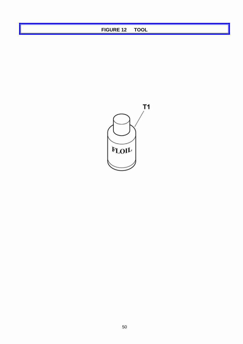
FIGURE 12 TOOL

51
LIST OF TOOL
FIGURE & KEY No.
PART NUMBER
RANK QTY DESCRIPTION REMARKS
T - 1 QY9-0057-000 1 LUBE, FLOIL KG107A, OIL
52
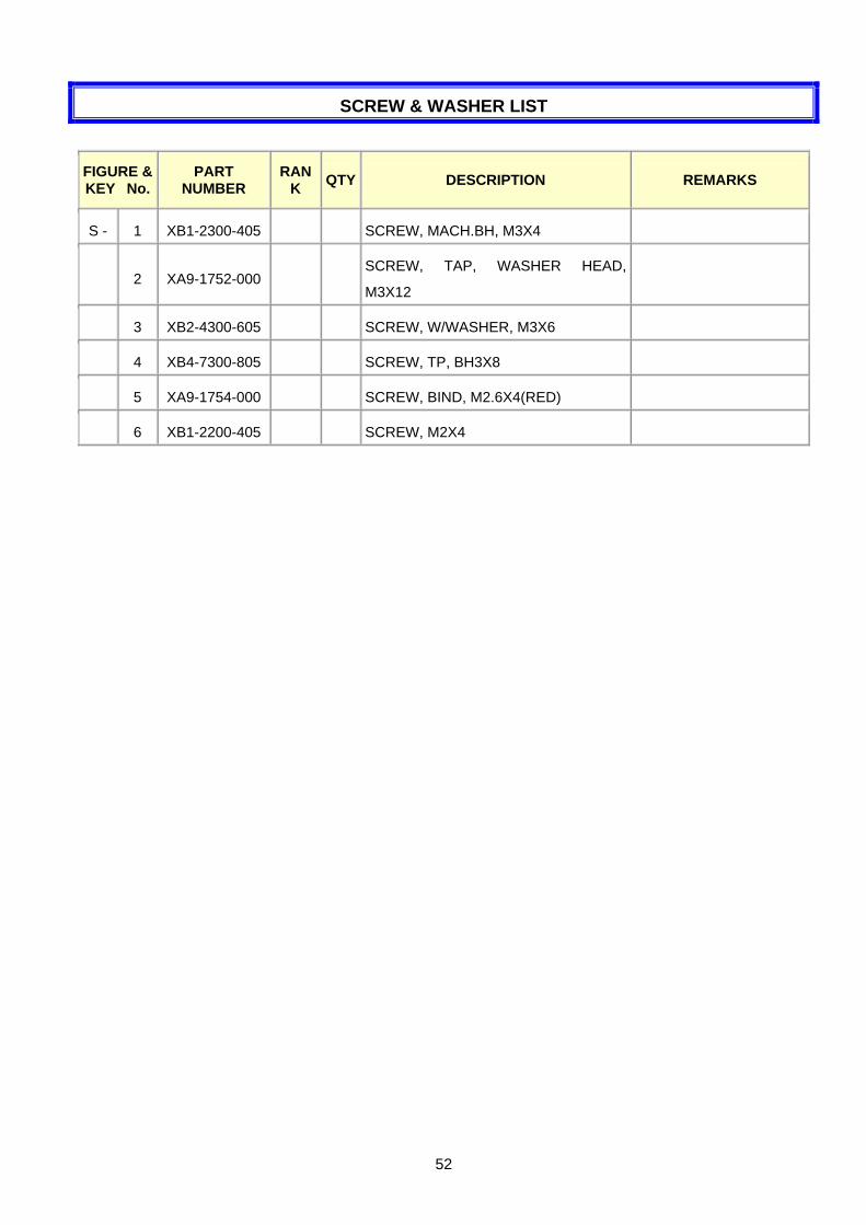
SCREW & WASHER LIST
FIGURE & KEY No.
PART NUMBER
RANK QTY DESCRIPTION REMARKS
S - 1 XB1-2300-405 SCREW, MACH.BH, M3X4
2 XA9-1752-000 SCREW, TAP, WASHER HEAD,
M3X12
3 XB2-4300-605 SCREW, W/WASHER, M3X6
4 XB4-7300-805 SCREW, TP, BH3X8
5 XA9-1754-000 SCREW, BIND, M2.6X4(RED)
6 XB1-2200-405 SCREW, M2X4
53
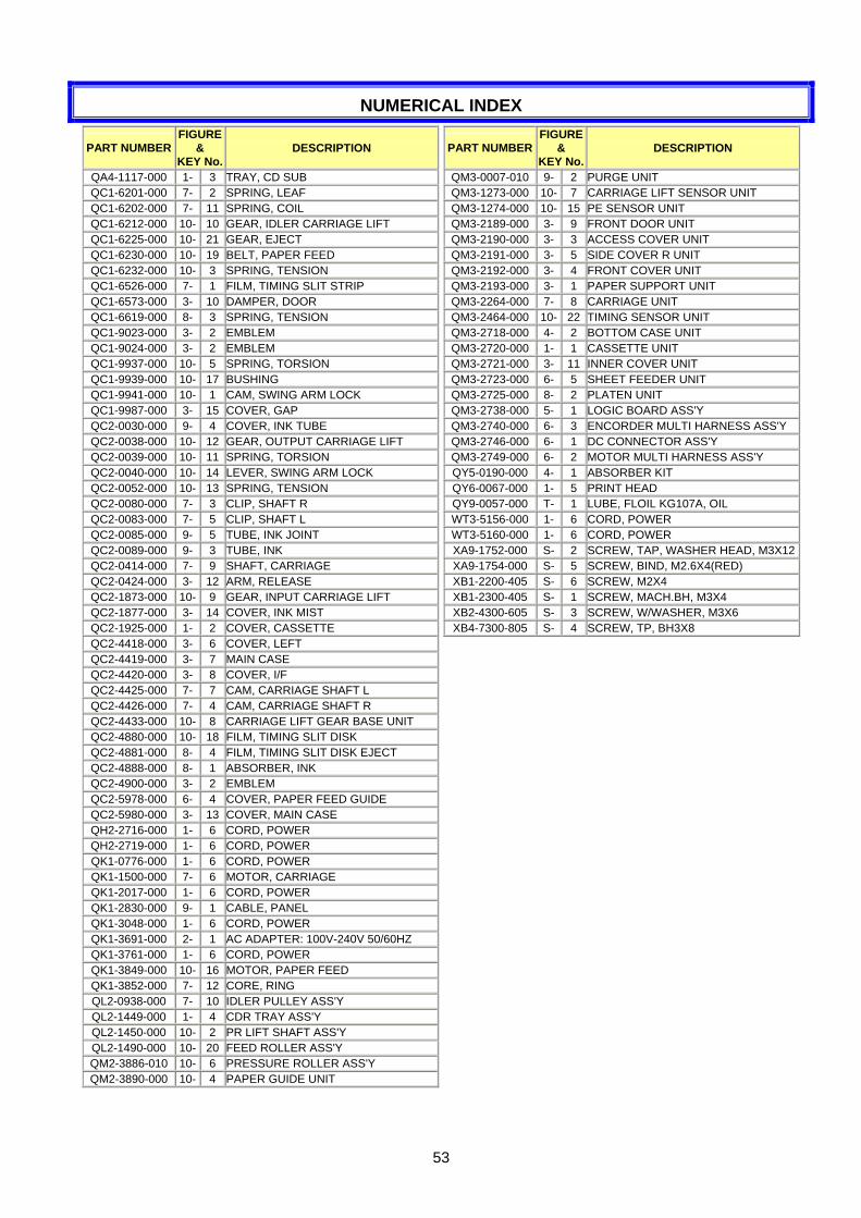
NUMERICAL INDEX
PART NUMBER FIGURE
& KEY No.
DESCRIPTION
QA4-1117-000 1- 3 TRAY, CD SUB QC1-6201-000 7- 2 SPRING, LEAF QC1-6202-000 7- 11 SPRING, COIL QC1-6212-000 10- 10 GEAR, IDLER CARRIAGE LIFT QC1-6225-000 10- 21 GEAR, EJECT QC1-6230-000 10- 19 BELT, PAPER FEED QC1-6232-000 10- 3 SPRING, TENSION QC1-6526-000 7- 1 FILM, TIMING SLIT STRIP QC1-6573-000 3- 10 DAMPER, DOOR QC1-6619-000 8- 3 SPRING, TENSION QC1-9023-000 3- 2 EMBLEM QC1-9024-000 3- 2 EMBLEM QC1-9937-000 10- 5 SPRING, TORSION QC1-9939-000 10- 17 BUSHING QC1-9941-000 10- 1 CAM, SWING ARM LOCK QC1-9987-000 3- 15 COVER, GAP QC2-0030-000 9- 4 COVER, INK TUBE QC2-0038-000 10- 12 GEAR, OUTPUT CARRIAGE LIFT QC2-0039-000 10- 11 SPRING, TORSION QC2-0040-000 10- 14 LEVER, SWING ARM LOCK QC2-0052-000 10- 13 SPRING, TENSION QC2-0080-000 7- 3 CLIP, SHAFT R QC2-0083-000 7- 5 CLIP, SHAFT L QC2-0085-000 9- 5 TUBE, INK JOINT QC2-0089-000 9- 3 TUBE, INK QC2-0414-000 7- 9 SHAFT, CARRIAGE QC2-0424-000 3- 12 ARM, RELEASE QC2-1873-000 10- 9 GEAR, INPUT CARRIAGE LIFT QC2-1877-000 3- 14 COVER, INK MIST QC2-1925-000 1- 2 COVER, CASSETTE QC2-4418-000 3- 6 COVER, LEFT QC2-4419-000 3- 7 MAIN CASE QC2-4420-000 3- 8 COVER, I/F QC2-4425-000 7- 7 CAM, CARRIAGE SHAFT L QC2-4426-000 7- 4 CAM, CARRIAGE SHAFT R QC2-4433-000 10- 8 CARRIAGE LIFT GEAR BASE UNIT QC2-4880-000 10- 18 FILM, TIMING SLIT DISK QC2-4881-000 8- 4 FILM, TIMING SLIT DISK EJECT QC2-4888-000 8- 1 ABSORBER, INK QC2-4900-000 3- 2 EMBLEM QC2-5978-000 6- 4 COVER, PAPER FEED GUIDE QC2-5980-000 3- 13 COVER, MAIN CASE QH2-2716-000 1- 6 CORD, POWER QH2-2719-000 1- 6 CORD, POWER QK1-0776-000 1- 6 CORD, POWER QK1-1500-000 7- 6 MOTOR, CARRIAGE QK1-2017-000 1- 6 CORD, POWER QK1-2830-000 9- 1 CABLE, PANEL QK1-3048-000 1- 6 CORD, POWER QK1-3691-000 2- 1 AC ADAPTER: 100V-240V 50/60HZ QK1-3761-000 1- 6 CORD, POWER QK1-3849-000 10- 16 MOTOR, PAPER FEED QK1-3852-000 7- 12 CORE, RING QL2-0938-000 7- 10 IDLER PULLEY ASS'Y QL2-1449-000 1- 4 CDR TRAY ASS'Y QL2-1450-000 10- 2 PR LIFT SHAFT ASS'Y QL2-1490-000 10- 20 FEED ROLLER ASS'Y QM2-3886-010 10- 6 PRESSURE ROLLER ASS'Y QM2-3890-000 10- 4 PAPER GUIDE UNIT
PART NUMBERFIGURE
& KEY No.
DESCRIPTION
QM3-0007-010 9- 2 PURGE UNIT QM3-1273-000 10- 7 CARRIAGE LIFT SENSOR UNIT QM3-1274-000 10- 15 PE SENSOR UNIT QM3-2189-000 3- 9 FRONT DOOR UNIT QM3-2190-000 3- 3 ACCESS COVER UNIT QM3-2191-000 3- 5 SIDE COVER R UNIT QM3-2192-000 3- 4 FRONT COVER UNIT QM3-2193-000 3- 1 PAPER SUPPORT UNIT QM3-2264-000 7- 8 CARRIAGE UNIT QM3-2464-000 10- 22 TIMING SENSOR UNIT QM3-2718-000 4- 2 BOTTOM CASE UNIT QM3-2720-000 1- 1 CASSETTE UNIT QM3-2721-000 3- 11 INNER COVER UNIT QM3-2723-000 6- 5 SHEET FEEDER UNIT QM3-2725-000 8- 2 PLATEN UNIT QM3-2738-000 5- 1 LOGIC BOARD ASS'Y QM3-2740-000 6- 3 ENCORDER MULTI HARNESS ASS'Y QM3-2746-000 6- 1 DC CONNECTOR ASS'Y QM3-2749-000 6- 2 MOTOR MULTI HARNESS ASS'Y QY5-0190-000 4- 1 ABSORBER KIT QY6-0067-000 1- 5 PRINT HEAD QY9-0057-000 T- 1 LUBE, FLOIL KG107A, OIL WT3-5156-000 1- 6 CORD, POWER WT3-5160-000 1- 6 CORD, POWER XA9-1752-000 S- 2 SCREW, TAP, WASHER HEAD, M3X12XA9-1754-000 S- 5 SCREW, BIND, M2.6X4(RED) XB1-2200-405 S- 6 SCREW, M2X4 XB1-2300-405 S- 1 SCREW, MACH.BH, M3X4 XB2-4300-605 S- 3 SCREW, W/WASHER, M3X6 XB4-7300-805 S- 4 SCREW, TP, BH3X8