Embed Size (px)
Citation preview
CANISTERIZED SATELLITE DISPENSER (CSD) DATA SHEET
2002337B 21 Jul 2014 Patent Pending planetarysys.com 1/28
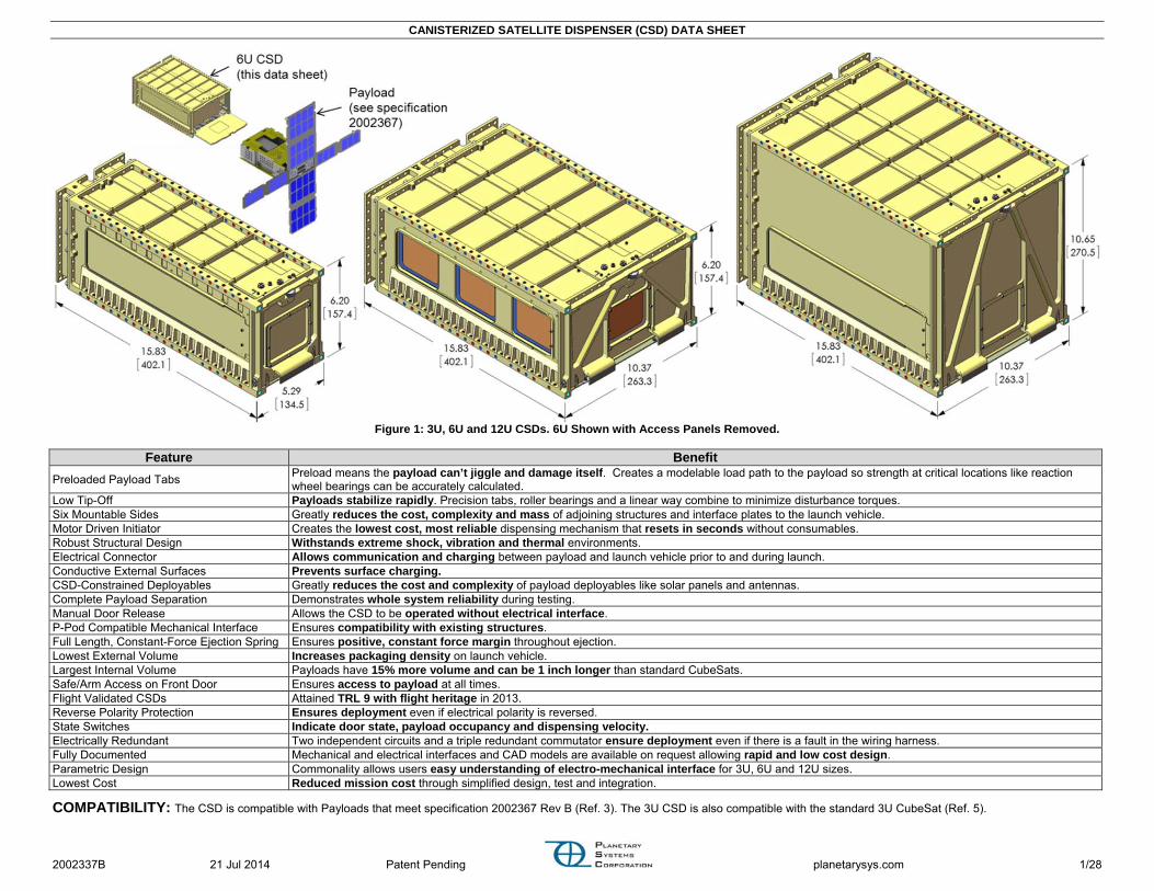
Figure 1: 3U, 6U and 12U CSDs. 6U Shown with Access Panels Removed.
Feature Benefit
Preloaded Payload Tabs Preload means the payload can’t jiggle and damage itself. Creates a modelable load path to the payload so strength at critical locations like reaction wheel bearings can be accurately calculated.
Low Tip-Off Payloads stabilize rapidly. Precision tabs, roller bearings and a linear way combine to minimize disturbance torques. Six Mountable Sides Greatly reduces the cost, complexity and mass of adjoining structures and interface plates to the launch vehicle. Motor Driven Initiator Creates the lowest cost, most reliable dispensing mechanism that resets in seconds without consumables. Robust Structural Design Withstands extreme shock, vibration and thermal environments. Electrical Connector Allows communication and charging between payload and launch vehicle prior to and during launch. Conductive External Surfaces Prevents surface charging. CSD-Constrained Deployables Greatly reduces the cost and complexity of payload deployables like solar panels and antennas. Complete Payload Separation Demonstrates whole system reliability during testing. Manual Door Release Allows the CSD to be operated without electrical interface. P-Pod Compatible Mechanical Interface Ensures compatibility with existing structures. Full Length, Constant-Force Ejection Spring Ensures positive, constant force margin throughout ejection. Lowest External Volume Increases packaging density on launch vehicle. Largest Internal Volume Payloads have 15% more volume and can be 1 inch longer than standard CubeSats. Safe/Arm Access on Front Door Ensures access to payload at all times. Flight Validated CSDs Attained TRL 9 with flight heritage in 2013. Reverse Polarity Protection Ensures deployment even if electrical polarity is reversed. State Switches Indicate door state, payload occupancy and dispensing velocity. Electrically Redundant Two independent circuits and a triple redundant commutator ensure deployment even if there is a fault in the wiring harness. Fully Documented Mechanical and electrical interfaces and CAD models are available on request allowing rapid and low cost design. Parametric Design Commonality allows users easy understanding of electro-mechanical interface for 3U, 6U and 12U sizes. Lowest Cost Reduced mission cost through simplified design, test and integration.
COMPATIBILITY: The CSD is compatible with Payloads that meet specification 2002367 Rev B (Ref. 3). The 3U CSD is also compatible with the standard 3U CubeSat (Ref. 5).

CANISTERIZED SATELLITE DISPENSER (CSD) DATA SHEET
2002337B 21 Jul 2014 Patent Pending planetarysys.com 2/28
TABLE OF CONTENTSFlight Heritage ........................................................................................................ 2 Description ............................................................................................................. 3 Benefits of Preloaded Tabs .................................................................................... 4 Parameters ............................................................................................................. 6 Mechanical Interface .............................................................................................. 8 Electrical Interface ............................................................................................... 11 Electrical Schematic ............................................................................................. 12 Payload in CSD .................................................................................................... 13 Testing ................................................................................................................. 14 Payload Ejection .................................................................................................. 15 Initiation Electrical Profiles ................................................................................... 15 Payload Volume ................................................................................................... 16 Operation and Integration .................................................................................... 17 CSD Constrained Deployables ............................................................................ 18 Fastening Payload to Ejection Plate .................................................................... 18 Reducing Dynamic Loading on Payload .............................................................. 19 Typical Applications ............................................................................................. 20 Test Support Equipment ...................................................................................... 26 Specifying and Ordering ...................................................................................... 27 Typical Lead Time ................................................................................................ 27 Training ................................................................................................................ 27 Future Developments ........................................................................................... 27 References ........................................................................................................... 28 Acknowledgements .............................................................................................. 28 CAD and Finite Element Models .......................................................................... 28 Tips and Considerations ...................................................................................... 28 Additional Information .......................................................................................... 28 Revision History ................................................................................................... 28
FLIGHT HERITAGE The CSD is at Technology Readiness Level (TRL) 9. A 3U CSD flew aboard the inaugural Falcon 9 v1.1 flight on September 2013 and released the 7-piece POPACS payload in orbit. See Ref. 6.
Figure 2: Integration of POPACS Mission (Ref. 2, 6)

CANISTERIZED SATELLITE DISPENSER (CSD) DATA SHEET
2002337B 21 Jul 2014 Patent Pending planetarysys.com 3/28
DESCRIPTION The Canisterized Satellite Dispenser (CSD) is a reliable, testable, and cost-effective deployment mechanism for small secondary or tertiary payloads. It fully encapsulates the payload during launch and thus provides mission assurance for both the primary payload and launch vehicle. All material in the primary load path is Table I for stress corrosion cracking. All external surfaces are electrically conductive chem-film aluminum alloy. The CSD is not ESD sensitive. This data sheet encompasses 3U, 6U and 12U CSDs. The CSD is easy to use and operate. The act of closing its door automatically preloads the payload tabs. There are no pyrotechnics. The door initiator is a DC brush motor with substantial flight heritage. The motor has EMI suppression. The CSD can be cycled in a matter of seconds without consumables. The motor, an excellent torque transducer, provides invaluable feedback to the health of the mechanism by monitoring voltage and current during each operation. The CSD has unique features that allow mounting to any face. This reduces the necessity for heavy interface structures and allows the CSDs to be densely packaged on the launch vehicle. It also contains an optional separation electrical connector to the payload.
Figure 3: CSD Features (6U Shown)

CANISTERIZED SATELLITE DISPENSER (CSD) DATA SHEET
2002337B 21 Jul 2014 Patent Pending planetarysys.com 4/28
BENEFITS OF PRELOADED TABS
Preloading the payload to the CSD by virtue of clamping the tabs creates a stiff invariant load path. This allows for accurate dynamic modeling to predict responses in anticipation of vibratory testing and space flight.
Figure 4: 6U Payload and Predicted Dynamic Response
Figure 5: Benefit of Tabs vs. Rails
Figure 6: Preloaded Tabs of a 3U Payload (Ref. 2)
Figure 7: Prediction of 3U Dynamic Response
CANISTERIZED SATELLITE DISPENSER (CSD) DATA SHEET
2002337B 21 Jul 2014 Patent Pending planetarysys.com 5/28
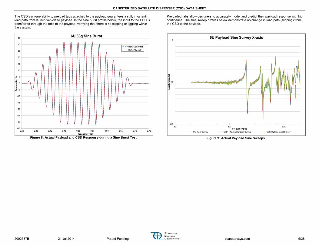
The CSD’s unique ability to preload tabs attached to the payload guarantees a stiff, invariant load path from launch vehicle to payload. In the sine burst profile below, the input to the CSD is transferred through the tabs to the payload, verifying that there is no slipping or jiggling within the system.
Figure 8: Actual Payload and CSD Response during a Sine Burst Test
Preloaded tabs allow designers to accurately model and predict their payload response with high confidence. The sine sweep profiles below demonstrate no change in load path (slipping) from the CSD to the payload.
Figure 9: Actual Payload Sine Sweeps

CANISTERIZED SATELLITE DISPENSER (CSD) DATA SHEET
2002337B 21 Jul 2014 Patent Pending planetarysys.com 6/28
PARAMETERS
Symbol Parameter Conditions Units 3U 6U 12U
Min Max Min Max Min Max
M Mass (1) Empty kg [lb]
3.37 [7.42]
3.41 [7.52]
4.49 [9.89]
4.54 [10.02]
5.55 [12.24]
5.61 [12.37]
Height Height, +Y in [mm]
6.187 [157.15]
6.207 [157.66]
6.187 [157.15]
6.207 [157.66]
10.640 [270.26]
10.660 [270.76]
Width Width, ±X in [mm]
5.285 [134.24]
5.305 [134.75]
10.355 [263.02]
10.375 [263.53]
10.355 [263.02]
10.375 [263.53]
CMXC Center of Mass, ±X Door closed, ejection plate position as if payload installed in [mm]
-0.23 [-6]
0.17 [4]
-0.23 [-6]
0.17 [4]
-0.23 [-6]
0.17 [4]
CMYC Center of Mass, ±Y Door closed, ejection plate position as if payload installed in [mm]
2.34 [59]
2.74 [70]
2.40 [61]
2.80 [71]
4.33 [110]
4.73 [120]
CMZC Center of Mass, ±Z Door closed, ejection plate position as if payload installed in [mm]
7.59 [193]
7.99 [203]
7.43 [189]
7.83 [199]
7.28 [185]
7.68 [195]
CMXO Center of Mass, ±X Door open in [mm]
-0.23 [-6]
0.17 [4]
-0.23 [-6]
0.17 [4]
-0.23 [-6]
0.17 [4]
CMYO Center of Mass, ±Y Door open in [mm]
2.22 [56]
2.62 [67]
2.24 [57]
2.64 [67]
3.95 [100]
4.35 [110]
CMZO Center of Mass, ±Z Door open in [mm]
8.12 [206]
8.52 [216]
8.17 [208]
8.57 [218]
8.46 [215]
8.86 [225]
IXX Mass Moment of Inertia About CM, door closed, empty lb*in2 [kg*m2]
230 [0.067]
254 [0.074]
327 [0.096]
362 [0.106]
548 [0.160]
605 [0.177]
IYY Mass Moment of Inertia About CM, door closed, empty lb*in2 [kg*m2]
221 [0.065]
244 [0.071]
410 [0.120]
453 [0.132]
530 [0.155]
585 [0.171]
IZZ Mass Moment of Inertia About CM, door closed, empty lb*in2 [kg*m2]
61 [0.018]
67 [0.020]
179 [0.052]
198 [0.058]
352 [0.103]
389 [0.114]
E Payload Ejection Energy (2) See Figure 19 for velocity estimate. J 2.7 5.4 5.4 10.8 5.4 10.8
V Voltage Provided from Launch Vehicle to Open Door Power to pins 1 & 2, return from pins 3 & 4 Vdc 22 34 22 34 22 34
RDI Winding Resistance of Door Initiator (3) -45 to +90 °C, includes internal CSD wiring ohm 7.4 13.0 7.4 13.0 7.4 13.0
LDI Inductance of Door Initiator At terminals mH 0.452 0.452 0.452
IP Peak Current Draw from Door Initiator (4) <0.005 sec A 1.7 4.9 1.7 4.9 1.7 4.9
IC Continuous Current Draw from Door Initiator (5) A 0.1 1.5 0.1 1.5 0.1 1.5
T Time to Initiate (Open Door) (5) -45 to +90 °C, <10e-5 torr sec 0.01 0.05 0.01 0.05 0.01 0.05
RS Switch Terminal Resistance Door and occupancy switches, closed circuit, includes internal CSD wiring, -45 to +90 °C ohm 0.046 0.107 0.046 0.107 0.046 0.107
ISR Current Capacity of Switch, Resistive 28 Vdc, <10e-5 torr, door and occupancy switches A - 2.5 - 2.5 - 2.5
ISI Current Capacity of Switch, Inductive 28 Vdc, <10e-5 torr, door and occupancy switches A - 1.5 - 1.5 - 1.5
PT Payload Travel Required for Occupancy Switch Change State +Z travel from launch position in
[mm] 12.1 [307]
13.2 [335]
13.2 [335]
13.2 [335]
DP Door Position for Door Switch Change of State Angle (0 deg is closed) deg 0.3 2.0 0.3 2.0 0.1 1.0

CANISTERIZED SATELLITE DISPENSER (CSD) DATA SHEET
2002337B 21 Jul 2014 Patent Pending planetarysys.com 7/28
Symbol Parameter Conditions Units 3U 6U 12U
Min Max Min Max Min Max
FEP Ejection Plate Force on Payload
During launch due to vibration (assuming 100g response). lbf [N] 0 22
[98] 0 43 [191] 0 86
[383]
During ejection due to spring force. lbf [N]
1.8 [8.0]
5.3 [23.6]
3.5 [15.6]
10.5 [46.7]
3.5 [15.6]
10.5 [46.7]
PRR Payload Rotation Rates After payload is fully ejected from CSD Deg/sec/axis 0 10 0 10 0 10
LVF Launch Vehicle Flatness (6,7) The structure adjoining the CSD. in [mm] 0.0 0.005
[0.13] 0.0 0.005 [0.13] 0.0 0.005
[0.13]
TML Total Mass Loss Per ASTM E 595-77/84/90 % 0.0 1.0 0.0 1.0 0.0 1.0
CVCM Collected Volatile Condensable Material Per ASTM E 595-77/84/90 % 0.0 0.1 0.0 0.1 0.0 0.1
DP LV De-Pressurization Rate (6) During launch psi/ sec 0.0 0.5 0.0 0.5 0.0 0.5
TS Survival Temperature Qualification limits. °C [°F]
-50 [-58]
+100 [+212]
-50 [-58]
+100 [+212]
-50 [-58]
+100 [+212]
TO Operational Temperature Qualification limits. °C [°F]
-45 [-49]
+90 [+194]
-45 [-49]
+90 [+194]
-45 [-49]
+90 [+194]
DX In-Flight Disconnect Location, +XPL Relative to Payload Origin in [mm]
1.606 [40.80]
1.616 [41.06]
4.093 [103.96]
4.103 [104.22]
4.093 [103.96]
4.103 [104.22]
L Life Allowable number of door closures by customer before refurbishment is required. - - 50 - 50 - 50
(1) Min: Includes 1 (3U) or 2 (6U/12U) ejection springs and no in-flight disconnect. Max: Includes 2 (3U) or 4( 6U/12U) ejection springs and the in-flight disconnect. Both values are nominal. Assume
a ±3% tolerance to account for machining variations. (2) Payload Ejection Velocity (∆V) [m/s] = (1+MP/MLV)*sqrt(2E/(MP(1+MP/MLV))). Where MP: payload mass [kg], MLV: mass of CSD + adjoining structure [kg]. (3) Actual winding resistance can be calculated by RDI = 10.3(1+0.004(Temperature [cel]-25)). (4) Actual Peak Current can be calculated by IP = V/RDI. (5) Door Initiator will continue to draw current (IC) until power is cut from LV. This is not detrimental to the CSD. LV may leave power on up to 0.5 secs after door limit switch opens. (6) These are requirements imposed on the launch vehicle. (7) This assumes the LV is a stiff structure like an aluminum plate. The flatness requirement can be loosened for more flexible structures. Contact PSC.

CANISTERIZED SATELLITE DISPENSER (CSD) DATA SHEET
2002337B 21 Jul 2014 Patent Pending planetarysys.com 8/28
MECHANICAL INTERFACE Dimensions apply to all CSD sizes unless the view specifically states otherwise (Ex. “3U only”). All CSD mounting surfaces are 6061-T6 aluminum alloy with chemical film per MIL-DTL-5541, Class 3. .
Figure 10: CSD Mechanical Interface Dimensions

CANISTERIZED SATELLITE DISPENSER (CSD) DATA SHEET
2002337B 21 Jul 2014 Patent Pending planetarysys.com 9/28
Figure 11: Mechanical Interface Views (cont.). Some views unique to 3U.
UNC

CANISTERIZED SATELLITE DISPENSER (CSD) DATA SHEET
2002337B 21 Jul 2014 Patent Pending planetarysys.com 10/28
Figure 12: Mounting Patterns Unique to 6U and 12U

CANISTERIZED SATELLITE DISPENSER (CSD) DATA SHEET
2002337B 21 Jul 2014 Patent Pending planetarysys.com 11/28
ELECTRICAL INTERFACE
Figure 13: Launch Vehicle Electrical Interface

CANISTERIZED SATELLITE DISPENSER (CSD) DATA SHEET
2002337B 21 Jul 2014 Patent Pending planetarysys.com 12/28
ELECTRICAL SCHEMATIC
Figure 14: CSD Electrical Schematic
(6) The Separation Electrical Connector is an in-flight disconnect (IFD). It is a custom connector provided by PSC that has significant space-flight heritage. The launch vehicle side of the connector
must be removed from the CSD prior to the initial payload installation. It may be re-attached to the CSD after payload installation and door closure. This ensures proper alignment of the connector halves. For more information see PSC document 2001025 Separation Connector Data Sheet (Ref. 4).

CANISTERIZED SATELLITE DISPENSER (CSD) DATA SHEET
2002337B 21 Jul 2014 Patent Pending planetarysys.com 13/28
PAYLOAD IN CSD The figure below shows a payload installed in the CSD. It also shows the size and location of access zones relative to the payload origin. Dimensions apply to all CSD sizes.
Figure 15: Payload Location in CSD

CANISTERIZED SATELLITE DISPENSER (CSD) DATA SHEET
2002337B 21 Jul 2014 Patent Pending planetarysys.com 14/28
TESTING All flight CSDs undergo environmental tests to verify workmanship. In addition, the CSDs have been qualified to levels that meet or exceed MIL-STD-1540. PSC records voltage and current during all initiations.
Table 1: Test Levels Test Qualification Flight EDU
Benchtop Separations
(1)
200 separations
10 separations
10 separations
Thermal Vacuum
Temperature: -45°C to +90°C Temperature: -20°C to +70°C
Not Tested
Pressure: <10E-5 torr Pressure: <10E-5 torr Cycles: 27 Cycles: 8
9 Separations +90°C: 22V, 28V, 34 V +23°C: 22V, 28V, 34 V -45°C: 22V, 28V, 34 V
1 Separation (hot or cold, 22V)
Strength as Sine Burst
(3)
Level: 50g (3U), 40g (6U) Cycles: 5 per axis
Level: 20g Cycles: 5 per axis Not Tested
Random Vibration
(2,3)
Level: 14.1 Grms Level: 10.0 Grms Not Tested Duration: 3 min/axis Duration: 1 min/axis
Payload Mass: Maximum Payload Mass: Maximum Shock (2,3)
See Figure 16 3 impacts per axis Not Tested Not Tested
(1) 1atm, ~23°C. (2) Full qualification was performed with CSD mounted via –Y face. Contact PSC if
planning to mount CSD via any other face. (3) 3U qualified with 6.1 kg payload. 6U qualified with 9.1 kg payload. Contact PSC if 6U
payload is heavier than 9.1 kg.
Figure 16: Shock Levels (Q=10)
Figure 17: PSC's Shock Test Fixture
Figure 18: Thermal Vacuum Testing in PSC's Chamber. Conveyor Rails Allow Complete
Payload Dispensing.
CANISTERIZED SATELLITE DISPENSER (CSD) DATA SHEET
2002337B 21 Jul 2014 Patent Pending planetarysys.com 15/28
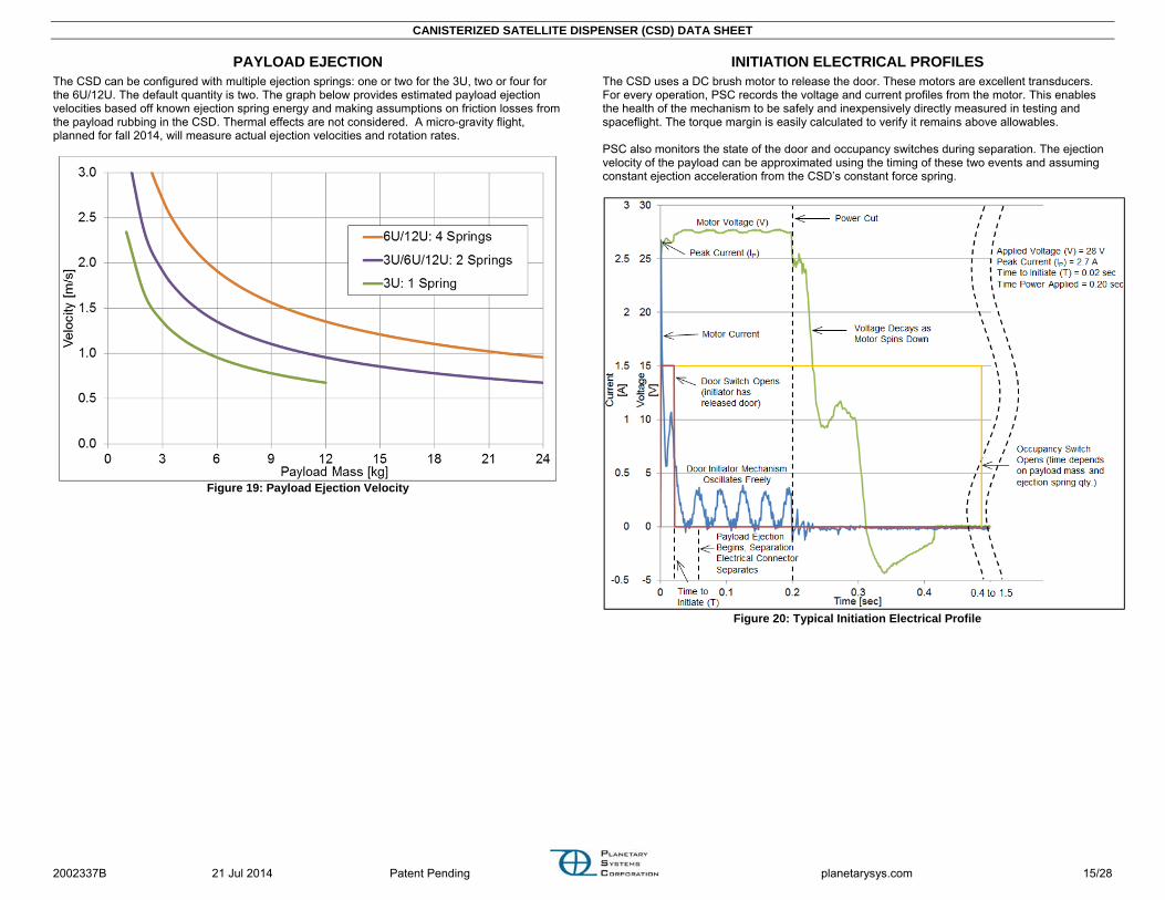
PAYLOAD EJECTION The CSD can be configured with multiple ejection springs: one or two for the 3U, two or four for the 6U/12U. The default quantity is two. The graph below provides estimated payload ejection velocities based off known ejection spring energy and making assumptions on friction losses from the payload rubbing in the CSD. Thermal effects are not considered. A micro-gravity flight, planned for fall 2014, will measure actual ejection velocities and rotation rates.
Figure 19: Payload Ejection Velocity
INITIATION ELECTRICAL PROFILES The CSD uses a DC brush motor to release the door. These motors are excellent transducers. For every operation, PSC records the voltage and current profiles from the motor. This enables the health of the mechanism to be safely and inexpensively directly measured in testing and spaceflight. The torque margin is easily calculated to verify it remains above allowables. PSC also monitors the state of the door and occupancy switches during separation. The ejection velocity of the payload can be approximated using the timing of these two events and assuming constant ejection acceleration from the CSD’s constant force spring.
Figure 20: Typical Initiation Electrical Profile

CANISTERIZED SATELLITE DISPENSER (CSD) DATA SHEET
2002337B 21 Jul 2014 Patent Pending planetarysys.com 16/28
PAYLOAD VOLUME The CSDs external volume is equivalent or smaller than other dispensers while simultaneously allowing the largest payload volume.
Figure 21: Comparison of 3U Payload Volumes. The CSD allows 15% more payload volume.
Figure 22: Comparison of 6U Payload Volumes. The CSD allows 9% more payload volume.

CANISTERIZED SATELLITE DISPENSER (CSD) DATA SHEET
2002337B 21 Jul 2014 Patent Pending planetarysys.com 17/28
OPERATION AND INTEGRATION Payload installation and integration is quick and straightforward. The figures below demonstrate the ease of attaching the CSD to a launch vehicle. The numerous mounting surfaces with tapped and through holes eliminate the need for additional interfacing structures. PSC document 3000257 CSD Operating and Integration Procedure shall be used for all payload installations, CSD operations and launch vehicle integration. Further, only trained personnel shall use the CSD. See section Training for details.
Figure 23: Installing 6U Payload in CSD
Figure 24: Using Thru Holes to Mount CSD via –Y Face
Figure 25: Using Reduced Clicker Head to Torque Fasteners
Figure 26: Installing CSD Initiator Electrical Harness
Figure 27: Installing LV Side Separation Electrical Connector
CANISTERIZED SATELLITE DISPENSER (CSD) DATA SHEET
2002337B 21 Jul 2014 Patent Pending planetarysys.com 18/28
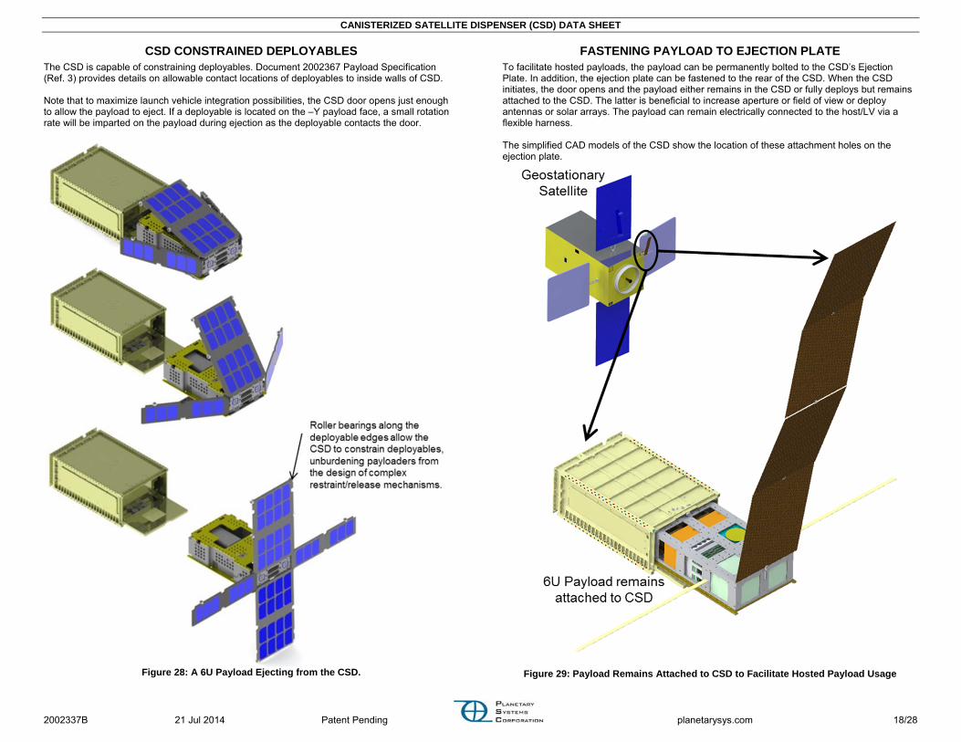
CSD CONSTRAINED DEPLOYABLES The CSD is capable of constraining deployables. Document 2002367 Payload Specification (Ref. 3) provides details on allowable contact locations of deployables to inside walls of CSD. Note that to maximize launch vehicle integration possibilities, the CSD door opens just enough to allow the payload to eject. If a deployable is located on the –Y payload face, a small rotation rate will be imparted on the payload during ejection as the deployable contacts the door.
Figure 28: A 6U Payload Ejecting from the CSD.
FASTENING PAYLOAD TO EJECTION PLATE To facilitate hosted payloads, the payload can be permanently bolted to the CSD’s Ejection Plate. In addition, the ejection plate can be fastened to the rear of the CSD. When the CSD initiates, the door opens and the payload either remains in the CSD or fully deploys but remains attached to the CSD. The latter is beneficial to increase aperture or field of view or deploy antennas or solar arrays. The payload can remain electrically connected to the host/LV via a flexible harness. The simplified CAD models of the CSD show the location of these attachment holes on the ejection plate.
Figure 29: Payload Remains Attached to CSD to Facilitate Hosted Payload Usage

CANISTERIZED SATELLITE DISPENSER (CSD) DATA SHEET
2002337B 21 Jul 2014 Patent Pending planetarysys.com 19/28
REDUCING DYNAMIC LOADING ON PAYLOAD The CSD tightly grips the payload’s tabs, creating a direct load path from the launch vehicle to the payload. To reduce these potentially harmful vibratory and shock loads the use of an isolation system is strongly recommended. A simple, low cost isolation system was successfully demonstrated during qualification testing of the CSDs. In addition to load dampening, using an isolation system may allow for increased payload mass. The figures below show the significant reduction in loading during random vibration and shock testing.
Figure 30: Isolation System Benefits during Random Vibration Testing
Figure 31: 6U CSD Vibration Testing with Isolation System
Figure 32: Isolation Benefits during Shock Testing
Figure 33: COTS Isolators Used on POPACS Mission

CANISTERIZED SATELLITE DISPENSER (CSD) DATA SHEET
2002337B 21 Jul 2014 Patent Pending planetarysys.com 20/28
TYPICAL APPLICATIONS
Figure 34: 6U Payload Deploying Through ESPA Port. CSD Mounted Directly via +Z Face.
Figure 35: CSDs Mounted to ESPA Grande
Figure 36: Nine 3U CSDs Mounted to Atlas V Aft Bulkhead Carrier (ABC) via Simple
Lightweight and Low Cost Isogrid Plate

CANISTERIZED SATELLITE DISPENSER (CSD) DATA SHEET
2002337B 21 Jul 2014 Patent Pending planetarysys.com 21/28
Figure 37: Four 12U CSDs on Aft of Stage
CSDs can dispense hosted payloads from large spacecraft. The separation connector enables trickle charging, thermal control and state-of-health telemetry for days, months, or years.
Figure 38: CSDs as Hosted Payloads

CANISTERIZED SATELLITE DISPENSER (CSD) DATA SHEET
2002337B 21 Jul 2014 Patent Pending planetarysys.com 22/28
Figure 39: Sixteen 6U CSDs Mounted Underneath Primary Payload
Figure 40: CSDs on Plate with 15 inch Lightband
The CSD can be used as a sequencer to initiate multiple CSDs via a single LV signal. The sequencer ‘payload’ contains all batteries and electronics thereby reducing the burden on the LV and facilitating launch opportunities. It can also contain a camera to record the separation events.
Figure 41: Using the CSD as a Payload Launch Sequencer
Figure 42: ISS Manipulator Arm Dispensing Six 6U Payloads

CANISTERIZED SATELLITE DISPENSER (CSD) DATA SHEET
2002337B 21 Jul 2014 Patent Pending planetarysys.com 23/28
The CSD can accommodate multi-piece payloads. Each discrete payload remains rigidly clamped via the tabs. The payloads need not occupy the entire length of the CSD (requires a custom matched CSD).
Figure 43: A Single CSD Can Dispense Multiple Payloads (Ref. 2, 6)
Figure 44: Multiple Payloads in a CSD
The ability to mount CSDs to any face maximizes launch opportunities and simplifies integration.
Figure 45: Five CSDs Stacked on a Single Mounting Plate

CANISTERIZED SATELLITE DISPENSER (CSD) DATA SHEET
2002337B 21 Jul 2014 Patent Pending planetarysys.com 24/28
Figure 46: CSD Mounted via –Y and +Y Faces Using Corner Rails
Figure 47: CSD Mounted via –X and +X Faces
Figure 48: CSD Mounted via –Z and +Z Faces
Figure 49: 3D Printed Payload Deploying from 6U CSD

CANISTERIZED SATELLITE DISPENSER (CSD) DATA SHEET
2002337B 21 Jul 2014 Patent Pending planetarysys.com 25/28
The CSD can accommodate existing CubeSats. The CSD’s internal preload system is removed and simple adapter rails are bolted inside. Contact PSC for details.
Figure 50: CSD CubeSat Conversion Kit
The CSD’s flat external surfaces and numerous mounting holes simplify addition of auxiliary features like thermal blankets, radiation shielding, redundant door restraint, solar cells, video cameras, etc.
Figure 51: CSDs Easily Accept Bolt-On Vibration and Thermal Isolation
Figure 52: Adding Auxiliary Equipment to the CSD

CANISTERIZED SATELLITE DISPENSER (CSD) DATA SHEET
2002337B 21 Jul 2014 Patent Pending planetarysys.com 26/28
TEST SUPPORT EQUIPMENT Verifying complete separation of the payload from the CSD is the only way to develop complete confidence in proper operation. For all testing PSC employs a custom conveyor mechanism that allows the payload to fully eject. PSC does not offer this for sale but will provide the production drawings to contracted customers upon request.
Figure 53: Two 6U CSDs Separating onto Conveyors in TVAC
Component level vibration testing of the payload prior to delivery of the CSD is often desired. The figures below show a means of simulating the CSD’s interface to the payload tabs. PSC does not offer this for sale or provide models/drawings.
Figure 54: Vibration Clamp Overview
The top and bottom clamps shall be aluminum alloy 6061-T6 with surface finish hard anodize per MIL-A-8625F, Type III, Class 1. The preload (clamping normal force) shall be approximately 4,000 lbf per tab (8,000 lbf total).
Figure 55: Clamp Section View
Figure 56: Contact Details (dimensions in inches)

CANISTERIZED SATELLITE DISPENSER (CSD) DATA SHEET
2002337B 21 Jul 2014 Patent Pending planetarysys.com 27/28
SPECIFYING AND ORDERING When ordering a CSD specify the exact configuration using the following system.
CSDs can also be purchased on the GSA Schedule. The prices listed are for EDU units only. Testing for flight units is an additional cost. Separation Electrical Connectors must be purchased separately. Note: EDUs will be indelibly marked “NOT FOR FLIGHT”.
TYPICAL LEAD TIME The typical lead-time for a standard (non-custom) CSD is 9 months. Table 2 breaks out the schedule tasks by month. An accelerated lead-time may be possible at additional cost.
Table 2: Lead Time for Standard CSDs Time, ARO [Months] 1 2 3 4 5 6 7 8 9
Procure Components Inspect and Assemble Test Readiness Review Test (Vibration, Separation Reliability, Tvac)
Ship
TRAINING Training is required prior to installing a payload, operating the CSD or integrating. Failure to obtain training prior to this will void the warranty. Training is offered at PSC at no charge.
FUTURE DEVELOPMENTS PSC is developing a 27U CSD for larger payloads. The design utilizes the same motor initiator and preload system as the smaller units. Contact PSC for additional information.
Figure 57: 27U CSD

CANISTERIZED SATELLITE DISPENSER (CSD) DATA SHEET
2002337B 21 Jul 2014 Patent Pending planetarysys.com 28/28
REFERENCES 1 Hevner, Ryan; Holemans, Walter, “An Advanced Standard for CubeSats”, Paper SSC11-II-
3, 25th Annual AIAA/USU Conference on Small Satellites, Logan, UT, August 2011. 2 Holemans, Walter; Moore, Gilbert; Kang, Jin, “Counting Down to the Launch of POPACS”,
Paper SSC12-X-3, 26th Annual AIAA/USU Conference on Small Satellites, Logan, UT, August 2012.
3 Payload Specification for 3U, 6U, 12U and 27U, 2002367 Rev B, Planetary Systems Corp., Silver Spring, MD, July 2014.
4 Separation Connector Data Sheet, 2001025 Rev C, Planetary Systems Corp, Silver Spring, MD, July 2013.
5 CubeSat Design Specification, Rev 12, California Polytechnic State University, CA, Aug 2009.
6 Hevner, Ryan, “Lessons Learned Flight Validating an Innovative Canisterized Satellite Dispenser”, Paper 978-1-4799-1622-1/14, 2014 IEEE Aerospace Conference, Big Sky, MT, January 2014.
ACKNOWLEDGEMENTS
PSC thanks the following individuals (in no implied order) that have contributed to the current maturation of the CSD:
Dr. Andrew Kalman, Pumpkin Inc. Adam Reif, Pumpkin Inc. Shaun Houlihan, Pumpkin Inc. Hans-Peter Dumm, AFRL Steve Buckley, ORS Dr. Jeff Welsh, ORS Craig Kief, COSMIAC Dr. Eric Swenson, AFIT Philip Smith, AFIT Dr. Jordi Puig-Suari, CalPoly Roland Coelho, CalPoly Dr. Robert Twiggs, Morehead State Gil Moore, Project POPACS Rex Ridenoure, Ecliptic Enterprises Corp. Tom Walkinshaw, Pocketcubeshop Bruce Yost, NASA AMES
CAD AND FINITE ELEMENT MODELS
Simplified CAD models of the CSD, in STEP format, are available at www.planetarysys.com. Finite element models are currently being created. Contact [email protected] for availability.
TIPS AND CONSIDERATIONS 1) The ejection spring force is often much less than the payload weight. Installing a removable
handle to the payload’s +Z face aides vertical installation of the payload into the CSD. 2) When deploying horizontally in 1g the payload will stop cantilevered prior to fully ejecting
due to friction. To avoid damage either guide the payload on rollers or prematurely stop it >3 inches early and then remove by hand.
3) As mentioned in the Fastening Payload to Ejection Plate section, the CSD ejection plate has a few small holes to assist hosted payloads. Obtain a CAD model of the CSD to ensure these holes do not interfere with the Payload’s inhibit switch locations.
4) The CSD can accommodate payloads heavier than those allowed per the Payload Specification, Ref 3. Reduce static equivalent load capability accordingly. Use of an isolation system is an easy means of accomplishing this.
ADDITIONAL INFORMATION Verify this is the latest revision of the specification by visiting www.planetarysys.com. Please contact [email protected] with questions or comments. Feedback is welcome in order to realize the full potential of this technology. PSC does not design or manufacture payloads.
REVISION HISTORY Revision Release Date Created By Reviewed By
- 25-Jul-2012 RH WH A 06-Aug-2013 RH WH B 21-Jul-2014 RH WH
Changes from previous revision:
Section(s) Changes
Cover Page - Updated Fig. 1. - Added several features and benefits.
Compatibility - Now compatible with Rev B of 2002367.
Description - Updated Fig.2 with real pictures. - Moved portion to Benefits of Preloaded Tabs.
Parameters
- M: Reduced mass. - Height & Width: Included min and max values. - CM & I: Updated values. - E: Updated values. - V: Reduced max voltage from 36 to 34. - Fep: updated values.
Mechanical Interface - Updated views with new design. - Increased tolerances on DB9 position. - Eliminated several -Z face mounting holes.
Testing - Added test fixture figures. - Tbl 1: reduced max voltage in Tvac.
Payload Ejection - Removed two spring options.
CSD Constrained Deployables - Updated to reference correct Payload Spec number.
Reducing Dynamic Loading on Payload
- Added shock attenuation plot. - Added 3U POPACS figure.
Typical Applications - Added many figures. - Removed some figures.
Test Support Equipment - Update TVac conveyor figure. - Added vibe fixture example.
Specifying and Ordering - Refined ejection spring options. CAD and Finite Element Models - Changed from CAD Models. Tips and Considerations - Added notes 3 & 4.
Flight Heritage, Benefits of Preloaded Tabs, Payload Volume, Operation and Integration, Fastening Payload to Ejection Plate, Typical Lead Time, Training, Future Developments, Acknowledgements
- Added.
Payload Installation and Operation - Deleted.