Embed Size (px)
Citation preview
BAOJ Cancer Research & TherapyMd.Mahfuzur R, BAOJ Cancer Res Ther 2018, 4: 2
4: 052
BAOJ Cancer Res Ther, an open access journal Volume 4; Issue 2; 052
Research
Quality Control of Intensity Modulated Radiation Therapy (IMRT) using Electronic Portal Imaging Devices (EPID)
Md.Mahfuzur R1*, Golam AZ2, Hasin AA3 and Md. Anwarul I1,4
1Department of Medical Physics & Biomedical Engineering, Gono Bishwabidyalay, Savar, Dhaka, Bangladesh2Medical Physicist, Department of Oncology and Radiotherapy Centre, Square Hospital Ltd., Dhaka, Bangladesh
3Chairman of the Dept. of medial physics and Biomedical Engineering, Dean, Faculty of Physical and Mathematical Sciences, Gono Bishwabidyalay, Savar, Dhaka, Bangladesh
4Chief medical physicist, Gummersbach Hospital, teaching Hospital of the University of Cologne, Germany
*Corresponding Author: Md.Mahfuzur R, Department of Medical Physics & Biomedical Engineering, Gono Bishwabidyalay, Savar, Dhaka, Bangladesh, E-mail: [email protected]
Sub Date: April 25th, 2018, Acc Date: May 18th, 2018, Pub Date: May 21st, 2018.
Citation: Md.Mahfuzur R, Golam AZ, Hasin AA and Md. Anwarul I (2018) Quality Control of Intensity Modulated Radiation Therapy (IMRT) using Electronic Portal Imaging Devices (EPID). BAOJ Cancer Res Ther 4: 052.
Copyright: © 2018 Md.Mahfuzur R. This is an open access article distributed under the terms of the Creative Commons Attribution License, which permits unrestricted use, distribution, and reproduction in any medium, provided the original author and source are credited.
Abstract
Radiation treatment has immense importance in treatment for cancer patients both in curative and palliative purposes. Modern radiation treatment facilities like IMRT or VMAT are major development in the delivery of radiation therapy with the potential to improve outcome by increasing local tumor control and by reducing normal tissue complication. IMRT is a new technology that introduces new potential for error into the delivery of radiation therapy and the quality checks can improve the care of cancer patients without subjecting them to unnecessary risks in our country.
Quality control is an essential step in IMRT. Existing methods, or quality controls (QC), or with better word barriers, are introduced as important steps of radiation treatment process with the purpose of prohibiting errors and thus avoiding an unwanted erroneous irradiation of the patient. The aims of study of this paper are to ensure the MLC positional accuracy and leaf speed, the relative dosimetric verification (Gamma index) Individual patient QA and absolute dosimetric verification. For MLC leaf positional accuracy and leaf speed, the picket fence test, synchronized segmented stripes test pattern (DMLC QA test patterns and procedures) provided by Varian medical system have been used. For each test individual test pattern for 120 MLC have been loaded by stand alone MLC workstation and played. For relative dosimetric verification all the test procedures like different dose in same depth, same dose in different depth, chair test and inhomogeneous test have been performed. For Individual patient QA phantom dose distribution, field in field technique, and composite plan was used. All the plans have been verified by measurement with EPID and evaluated by Gamma index. For absolute dose verification all the plans have been delivered and measurement by a 0.3 cc Semi Flex chamber along with a PTW solid water phantom. Relative and absolute dose verifications have been followed by Protocol of Quality control
for Intensity Modulated Radiation Therapy, as in the Recommendation No.15. In picket Fence and Synchronized Segmented Stripes test, match-lines appear at -10.0, -5.0, 0.0, 5.0, 10.0 and -12.0, -8.0, -4.0, 0.0, 4.0, 8.0, 12.0 cm respectively from the center of the field The Pass rate of Gamma Index for picket Fence test were 97%, Mean & Standard deviation 99.95% & 0.053%. The Pass rate of Gamma Index for the different dose in same depth, same dose in different depth, chair test and inhomogeneous test were 97.0% & Mean & Standard deviation 99.5% and 0.259% at the pixel range in -1.00 to 1.00 & 1.00 to 2.00 respectively. Verification of Pass rate of Gamma Index for a field-by-field basis and composite treatment plan test were 99.8& and 99.6% respectively. Calculated and measured absolute dose for three patients were 2.050 & 1.970 (% deviation 4.06), 1.728 & 1.730 (% deviation -0.011) and 1.270 & 1.250 (% deviation 1.6).
Keywords: Intensity Modulated Radiation Therapy; Quality Assur-ance; Quality control; Electronic Portal Imaging Device Gamma Index; Computerized Radiotherapy Treatment Planning System
Volume 4; Issue 2; 052
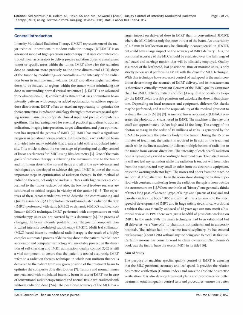
Page 2 of 26Citation: Md.Mahfuzur R, Golam AZ, Hasin AA and Md. Anwarul I (2018) Quality Control of Intensity Modulated Radiation Therapy (IMRT) using Electronic Portal Imaging Devices (EPID). BAOJ Cancer Res Ther 4: 052.
BAOJ Cancer Res Ther, an open access journal
General Introduction
Intensity Modulated Radiation Therapy (IMRT) represents one of the ma-jor technical innovations in modern radiation therapy (RT).IMRT is an advanced mode of high-precision radiotherapy that uses computer-con-trolled linear accelerators to deliver precise radiation doses to a malignant tumor or specific areas within the tumor. IMRT allows for the radiation dose to conform more precisely to the three-dimensional (3-D) shape of the tumor by modulating—or controlling—the intensity of the radia-tion beam in multiple small volumes. IMRT also allows higher radiation doses to be focused to regions within the tumor while minimizing the dose to surrounding normal critical structures [1]. IMRT is an advanced three-dimensional (3D) conformal treatment that uses nonuniform beam intensity patterns with computer added optimization to achieve superior dose distribution. IMRT offers an excellent opportunity to optimize the therapeutic ratio in radiation oncology through tumor coverage and spar-ing normal tissue by appropriate clinical input and precise computer al-gorithms. The increasing need for essential practical guidelines to address indication, imaging interpretation, target delineation, and plan optimiza-tion has inspired the genesis of IMRT [2]. IMRT has made a significant progress in radiation therapy centers. In this method, each radiation beam is divided into many subfields that create a field with a modulated inten-sity. This article is about the various steps of planning and quality control of linear accelerators for IMRT, using film dosimetry [3]. One of the main goals of radiation therapy is delivering the maximum dose to the tumor and minimum dose to the normal tissue and all of the new advances and techniques are developed to achieve this goal. IMRT is one of the most important steps in optimization of radiation therapy. In this method of radiation therapy, not only the isodose surfaces with high values are con-formed to the tumor surface, but also, the low level isodose surfaces are conformed to critical organs in vicinity of the tumor [4] [5].The objec-tives of these recommendations are to describe the commissioning and Quality assurance (QA) for photon intensity-modulated radiation therapy (IMRT) performed with static (sMLC) or dynamic (dMLC) multileaf col-limator (MLC) technique. IMRT performed with compensators or with tomotherapy units are not covered by this document [6].The process of changing the beam intensity profile to meet the goal of composite plan is called intensity modulated radiotherapy (IMRT). Multi leaf collimator (MLC) based intensity modulated radiotherapy is the result of a highly complex automated process of delivering dose to the patient. While linear accelerator and computer technology will inevitably proceed in the direc-tion of self-checking and IMRT automation, quality control (QC) is still a vital component to ensure that the patient is treated accurately. IMRT refers to a radiation therapy technique in which non uniform fluence is delivered to the patient from any given position of the treatment beam to optimize the composite dose distribution [7]. Tumors and normal tissues are irradiated with modulated intensity beam in case of IMRT but in case of conventional radiotherapy tumors and normal tissue are irradiated with uniform radiation dose [2-6]. The positional accuracy of the MLC has a
larger impact on delivered dose in IMRT than in conventional 3DCRT, where the MLC defines only the outer border of the beam. An uncertainty of 1-2 mm in leaf location may be clinically inconsequential in 3DCRT, but could have a large impact on the accuracy of IMRT delivery. Thus, the positional accuracy of the MLC should be evaluated over the full range of leaf travel and carriage motion that will be clinically employed. Quality assurance of the leaf speed, leaf position vs. time or monitor units, is only strictly necessary if performing IMRT with the dynamic MLC technique. With this technique however, exact control of leaf speed is the main con-dition determining the accuracy of IMRT delivery, and its measurement is therefore a critically important element of the IMRT quality assurance chain for dMLC delivery. Patient specific QA requires the possibility to ap-ply the IMRT fields to a slab phantom and calculate the dose in that phan-tom. Depending on local resources and equipment, different QA checks may be performed, and it is the responsibility of the medical physicist to evaluate the needs [6] [8] [9]. A medical linear accelerator (LINAC) gen-erates the photons, or x-rays, used in IMRT. The machine is the size of a small car-approximately 10 feet high and 15 feet long. The energy of the photon or x-ray, in the order of 10 millions of volts, is generated by the LINAC to penetrate the patient’s body to the tumor. During the 15 or so minutes of treatment, the patient is required to lie still on the treatment couch while the linear accelerator delivers multiple beams of radiation to the tumor from various directions. The intensity of each beam’s radiation dose is dynamically varied according to treatment plan. The patient usual-ly will not feel any sensation while the radiation is on, but will hear noise from the machine, and may smell an odor from the electronic equipment, or see the warning indicator light. The noises and odors from the machine are normal. The patient will be in the room alone during the treatment pe-riod with constant monitoring from the radiation therapists from outside the treatment room [1].When one thinks of ‘‘history’’ one generally thinks of times long past, of ancient Egypt, of Kings and Queens of England and parodies such as the book ‘‘1066 and all that’’. It is a testament to the sheer speed of development of IMRT and its huge anticipated clinical worth that a subject that was virtually unheard of 15 years ago can now merit a his-torical review. In 1990 there were just a handful of physicists working on IMRT. In the mid-1990s the main techniques had been established but all deliveries were ‘‘one-offs’’, to phantoms not patients, and in university hospitals. The subject had not become interdisciplinary. By has entered our language (about 1996) without anyone being able to recall its first use. Certainly no-one has come forward to claim ownership. Ned Sternick’s book was the first to have the words IMRT in its title [10].
Aim of Study
The purpose of machine specific quality control of IMRT is assuring that the MLC positional accuracy and leaf speed. It provides the relative dosimetric verification (Gamma index) and sows the absolute dosimetric verification. It is also develop treatment plans and procedures for better treatment٫ establish quality control tests and procedures٫ ensure the better
Volume 4; Issue 2; 052
Page 3 of 26Citation: Md.Mahfuzur R, Golam AZ, Hasin AA and Md. Anwarul I (2018) Quality Control of Intensity Modulated Radiation Therapy (IMRT) using Electronic Portal Imaging Devices (EPID). BAOJ Cancer Res Ther 4: 052.
BAOJ Cancer Res Ther, an open access journal
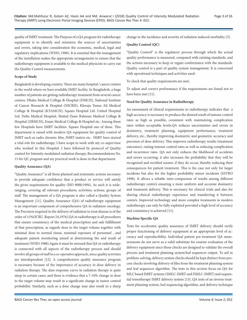
quality of IMRT treatment. The Purpose of a QA program for radiotherapy equipment is to identify and minimize the sources of uncertainties and errors, taking into consideration the economic, medical, legal and regulatory implications (WHO, 1988). It is essential that the management of the installation makes the appropriate arrangements to ensure that the radiotherapy equipment is available to the medical physicists to carry out the Quality Control measurements.
Scope of Study
Bangladesh is developing country. There are many hospital / cancer centres in the world where we have available IMRT facility. In Bangladesh, a huge number of patients are getting radiotherapy treatment from several cancer centres: Dhaka Medical College & Hospital (DMCH), National Institute of Cancer Research & Hospital (NICRH), Khwaja Yunus Ali Medical College & Hospital (KYAMCH), Square Hospital Ltd. United Hospital Ltd. Delta Medical Hospital, Shahid Ziaur Rahman Medical College & Hospital (ZRMCH), Enam Medical College & Hospital etc. Among them few Hospitals have IMRT facilities. Square Hospital one of these. This department is raised with modern QA equipment for quality control of IMRT such as radio chromic film, IMRT matrix etc. IMRT have started a vital role for radiotherapy. I have scope to work with my co-supervisor who worked in this Hospital. I have followed by protocol of Quality control for Intensity modulated radiation therapy, Recommendations No. 15 for QC program and my practical work is done in that department.
Quality Assurance (QA)
“Quality Assurance” is all those planned and systematic actions necessary to provide adequate confidence that a product or service will satisfy the given requirements for quality (ISO 9000:1994). As such it is wide-ranging, covering all relevant procedures; activities; actions; groups of staff. The management of a QA program is also called a Quality System Management [11]. Quality Assurance (QA) of radiotherapy equipment is an important component of comprehensive QA in radiation oncology. The Precision required in the delivery of radiation to treat disease is of the order of ±5%(ICRU ,Report 24,1976).QA in radiotherapy is all procedures that ensure consistency of the medical prescription and safe fulfillment of that prescription, as regards dose to the target volume together with minimal dose to normal tissue, minimal exposure of personnel , and adequate patient monitoring aimed at determining the end result of treatment (WHO 1988).Again it must be stressed that QA in radiotherapy is connected with all aspects of the radiotherapy process and should involve all groups of staff in a co-operative approach, since quality activities are interdependent [12]. A comprehensive quality assurance program is necessary because of the importance of accuracy in dose delivery in radiation therapy. The dare-response curve in radiation therapy is quite steep in certain cases, and there is evidence that a 7-10% change in dose to the target volume may result in a significant change in tumor control probability. Similarly, such as a dose change may also result in a sharp
change in the incidence and severity of radiation induced morbidity [3].
Quality Control (QC)
“Quality Control” is the regulatory process through which the actual quality performance is measured, compared with existing standards, and the actions necessary to keep or regain conformance with the standards. Quality control is a part of quality system management. It is concerned with operational techniques and activities used:
To check that quality requirements are met;
To adjust and correct performance if the requirements are found not to have been met [11].
Need for Quality Assurance in Radiotherapy
An assessment of clinical requirements in radiotherapy indicates that a high accuracy is necessary to produce the desired result of tumour control rates as high as possible, consistent with maintaining complication rates within acceptable levels.QA reduces uncertainties and errors in dosimetry, treatment planning, equipment performance, treatment delivery, etc., thereby improving dosimetric and geometric accuracy and precision of dose delivery. This improves radiotherapy results (treatment outcomes), raising tumour control rates as well as reducing complication and recurrence rates. QA not only reduces the likelihood of accidents and errors occurring, it also increases the probability that they will be recognized and rectified sooner, if they do occur, thereby reducing their consequences for patient treatment. This is the case not only for larger incidents but also for the higher probability minor incidents (ESTRO 1998). It allows a reliable inter-comparison of results among different radiotherapy centre’s ensuring a more uniform and accurate dosimetry and treatment delivery. This is necessary for clinical trials and also for sharing clinical radiotherapy experience and transferring it between centre’s. Improved technology and more complex treatments in modern radiotherapy can only be fully exploited provided a high level of accuracy and consistency is achieved [11].
Machine Specific QA
Tests for accelerator quality assurance of IMRT delivery should verify proper functioning of delivery equipment at an appropriate level of ac-curacy and reproducibility. Individual patient pre-treatment QA meas-urements do not serve as a valid substitute for routine evaluation of the delivery equipment since those checks are designed to validate the overall process and treatment planning system/leaf sequencer output. To aid in problem-solving, delivery system checks should be kept distinct from pro-cess checks involving delivery of files from the treatment planning system and leaf sequencer algorithm. The tests in this section focus on QA for MLC based IMRT systems (SMLC-IMRT and DMLC-IMRT) and sequen-tial tomotherapy IMRT delivery system [13]. QA tests of an inverse treat-ment planning system, leaf sequencing algorithm, and delivery technique
Volume 4; Issue 2; 052
Page 4 of 26Citation: Md.Mahfuzur R, Golam AZ, Hasin AA and Md. Anwarul I (2018) Quality Control of Intensity Modulated Radiation Therapy (IMRT) using Electronic Portal Imaging Devices (EPID). BAOJ Cancer Res Ther 4: 052.
BAOJ Cancer Res Ther, an open access journal
involves a subset of checks from the commissioning process [5,14].
Patient Specific QA
In IMRT, patient specific QA is of great importance as the segmentation of an individual treatment field leads to complex patterns of intensity dis-tributions as well as non-trivial MU settings. The whole treatment plan must therefore be checked before being applied to the patient. In addi-tion, patient specific dosimetry should be performed for each individual treatment plan. Such a dosimetric verification involves the measurement of dose distributions in a phantom and the measurement of the absolute dose for a representative point. An independent check calculation of the MU values (determined by the treatment planning system) may replace the absolute dose measurement.
EPID (Electronic Portal Imaging Device)
The aS500 EPID is 01 mm copper plate. It is phosphor scintillating layer (Kodak Lanex Fast B-Gd2O2S:Tb, 70 mg/cm3) and Array of photodiodes. It is Amorphous Silicon panel. It is each pixel consists of light sensitive photodiode and thin film transistor. It is 16-bit ADC [15].
Portal imaging is frequently applied in order to check geometric accuracy of the patient set-up with respect to the position of the radiation beam. The purpose of portal imaging is in particular:
To verify the field placement, characterized by the isocenter or another reference point, relative to anatomical structures of the patient, during the actual treatment.
Verify that the beam aperture (blocks or MLC) has been properly pro-duced and registered [11].
.As mentioned earlier, Electronic portal imaging devices (EPIDs) have been mounted on linear accelerators at many centers for verification of patient position. It is a logical extension of EPID technology to investigate applying such systems to IMRT dosimetry. Dosimetric applications have been investigated for charge-coupled camera devices (CCD), scanning liquid ionization chamber (SLIC) imagers, and active matrix flat panel imagers (AMFPI). In applying these systems for dosimetry, the systems may need to be operated in a mode different from that used clinically for patient position verification (radiographic or continuous acquisition modes). Additional software may also be required which is not available commercially yet. To use an EPID for dosimetric verification, the EPID re-sponse must be characterized for dose, dose rate, field size, and leaf speed (if DMLC delivery) dependence. Corrections are required and depend on the construction of the system. In addition, a portal dose prediction or portal dose image must be calculated to evaluate the measurements.CCD EPIDs have been applied to DMLC dosimetric measurements us-ing a modified system that includes a 1mm thick stainless steel slab in addition to the fluorescent layer [16]. Corrections are applied for the dark frame, the system’s non-linear response, nonuniform spatial response, and
optical cross talk. The application of a convolution kernel to correct for difference in absolute dose and penumbra for small fields has improved the response of the system for fields less than 3×3 cm2 [17]. Agreement between the CCD-EPID and measurements was within 2% for large fields measured with an ion chamber and for small fields measured with a line-ar diode array. Commercial SLIC EPIDs have also been characterized for dosimetric measurements for SMLC-IMRT and DMLC-IMRT. Different acquisition modes have been used for SMLC and DMLC delivery. A prob-lem with using this device for dosimetry is the need for equilibrium in the iso-octane layer of the device which led to measurements of only one segment per minute in one experiment [18,19,20]. Multiple investigators have found the agreement within about 2% with ion chamber and film data except in steep gradient regions. The final EPID systems that have recently been characterized for dosimetric applications are active matrix flat panel imagers (AMFPIs). Commercially, the systems have a fluores-cent layer above the imager area which adversely affects the dosimetric response [21]. The imager response has been modeled with Monte Carlo, deconvolution, and empirical methods for SMLC and DMLC delivery and agreement of approximately 2% has been measured by multiple investi-gators [22,23,24]. Further application of EPIDs for individual IMRT field verification is expected to continue. Commercial systems, including soft-ware, are still under development. Once such systems are in place, they offer great potential for saving time for verification of individual IMRT fields [13].
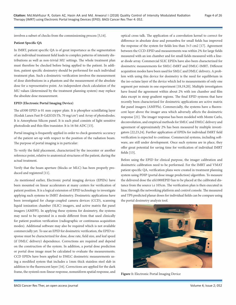
Before using the EPID for clinical purpose, the imager calibration and dosimetric calibration need to be performed. For the IMRT and VMAT patient specific QA, verification plans were created in treatment planning system using PDIP (portal dose image prediction) algorithm. To measure the delivered dose the aSi1000EPID has to be placed at the calibrated dis-tance from the source i.e 105cm. The verification plan is then executed in linac through the networking platform and control console. The measured and TPS predicted planar doses for individual fields can be compare using the portal dosimetry analysis tool.
Figure 1: Electronic Portal Imaging Device
Volume 4; Issue 2; 052
Page 5 of 26Citation: Md.Mahfuzur R, Golam AZ, Hasin AA and Md. Anwarul I (2018) Quality Control of Intensity Modulated Radiation Therapy (IMRT) using Electronic Portal Imaging Devices (EPID). BAOJ Cancer Res Ther 4: 052.
BAOJ Cancer Res Ther, an open access journal
Different Protocol of Quality Control of IMRT using EPID
The execution of the checks described in this document requires the appropriate allocation of time and of human resources, which directly affects the daily workload of the treatment machines. The quality assurance procedures should be considered as an integral part of the machine workload and the required time should be allocated within the normal working hours. The work of medical physicists, or delegated coworkers, during evenings or weekends should be considered only in exceptional cases, or for urgent interventions. Test frequencies are expressed as (a) weekly (b) monthly (c) quarterly and (d) annually. We represent one protocols and its tolerance limits for Quality Control of IMRT. The most popular protocol of Quality control for Intensity modulated radiation therapy, Recommendations No. 15 is used all over the world.
The three most popular Societies in all over the world are:
SGSMP
SSRPM
SSFMP
Swiss Society for Radiobiology and Medical Physics (SSRMP)
Member of the European Federation of Organisations for Medical Physics (EFOMP) and the International Organization for Medical Physics (IOMP)
SGSMP, SSRPM & SSRFM Protocol of QC of IMRT
The positional accuracy of the MLC has a larger impact on delivered dose in IMRT than in conventional 3DCRT, where the MLC defines only the outer border of the beam. An uncer- tainty of 1-2 mm in leaf location may be clinically inconsequential in 3DCRT, but could have a large impact on the accuracy of IMRT delivery [8]. Thus, the positional accuracy of the MLC should be evaluated over the full range of leaf travel and carriage motion that will be clinically employed. A simple test for the most impor-tant factors mentioned above is the acquisition and analysis of a match line-pattern usually called the “garden fence test”. These tests rely on the matching of adjacent strips producing narrow strips (e.g. 5 mm). An ob-vious advantage of this method is that the delivered and recorded patterns can be inspected visually to detect improper positioning of leaves with a precision of about 0.5 mm. Additionally, the position of the stripes, and consequently that of the leaves, can be simply measured in relation to the marked isocenter with a ruler. Quality assurance of the leaf speed, i.e., of leaf position vs. time or monitor units, is only strictly necessary if per-forming IMRT with the dMLC technique. With this technique however, exact control of leaf speed is the main condition determining the accuracy of IMRT delivery, and its measurement is therefore a critically important element of the IMRT QA chain for dMLC delivery. Leaf speed instability may arise from mechanical or steering problems or also due to the calibra-tion technique employed.
A simple test can be performed by an MLC test pattern where the leaf pairs move with constant gap and constant speed during beam on, possi-bly using different gap width and different speeds for different leaf pairs. The delivered dose should be uniform in travelling direction of the leaves, which can be checked with a dosimetric film or a portal imaging device. Furthermore, it should be correct in absolute dosimetry and independent of the gantry angle, which can be checked with measurement in the cen-tral axis using a detector whose sensitivity is suitable for the effect to be measured (e.g. an ionising chamber). Variations in measured dose with this test should not exceed ± 2 %.
“Quality control of treatment planning systems for teletherapy” [25] are considered to be the foundations of TPS QA for IMRT. Starting from these recommendations ensures that the dose calculations for the patients are as accurate as possible. The final dose distribution should always be calculat-ed with a state of the art algorithm with heterogeneity corrections, where possible using the best available algorithm provided by the TPS, even if during the optimization a simplified dose calculation is used. All the re-sults have to be displayed and evaluated under these conditions.
The measurements are meant to verify the effect of the optimization rather than the dose calculation,
Different doses at a given depth.
Same dose at different depth. A similar test as 1 above, but three regions at different depths but the same dose = D0.
An oblique beam with a single dose prescription at a single depth.
Single dose prescription at a single depth with a density hetero-geneity partially occluding the incident beam.
Test for dMLC dosimetric model parameters.
Clinical test cases.
In this protocol IMRT commissioning, acceptance and quality controls main heading for linac and treatment planning system are:
Radiation protection.
Basic dosimetry.
MLC positional accuracy.
MLC penumbra.
Leaf speed.
MLC transmission.
MLC control issues.
Extracness of the optimization.
Dosimetric verification of the whole process.

Volume 4; Issue 2; 052
Page 6 of 26Citation: Md.Mahfuzur R, Golam AZ, Hasin AA and Md. Anwarul I (2018) Quality Control of Intensity Modulated Radiation Therapy (IMRT) using Electronic Portal Imaging Devices (EPID). BAOJ Cancer Res Ther 4: 052.
BAOJ Cancer Res Ther, an open access journal
Clinical test cases should be performed in order to test the optimization algorithm in realistic clinical conditions. The selected test cases should cover the same geometry and dose constraints applied to the planning target volume (PTV) and organs at risk (OAR) relationship in order to validate a more clinical situation (heterogeneity, conflicting constraint, etc…). Note: if the patient QA is applied with measurement and not only by calculation from log files this point is less critical. Particular attention should be paid to:
The variety of target volume sizes and shapes should encompass the clinical range;
The sizes and shapes of OAR, as well as the geometric relation-ship among them, should be modelled from clinical cases;
The placement of targets should be varied to provide verifica-tion of the treatment planning and delivery systems throughout the available delivery and planning space;
The treatment plan prescriptions used for testing purposes should provide regions of high dose gradient such that the spatial localization accuracy can be determined in all three directions.
Gamma Index
3D Gamma index is one of the metrics which have been widely used for clinical routine patient specific quality assurance for IMRT, Tomotherapy and VMAT. The algorithms for calculating the 3D Gamma index using global and local methods implemented [26]. With increasing complexity of radiotherapy delivery from 3D-CRT to IMRT, VMAT and Tomother-apy, patient-specific quality assurance (QA) for patient plans is gradually moving away from verifying the planar dose and the dose at one point to verifying the dose distribution in three dimensional (3D) space [27]. The basic task for patient-specific QA based on 3D dosimetry is to com-pare two data sets of points of known spatial position and an associated absorbed dose value. One data set is usually 3D dose calculated in pa-tient or phantom geometry by the treatment planning system (TPS) and another is the measured dose in the phantom or reconstructed dose in patient from 2D detector measured dose or fluence [28]. Gamma index is the measurement that integrates more than one type of evaluation, when a large amount of dose data needs to be reviewed quickly. As for QA it is hardly needed. This tool may be applied to data with limited possibility. During the early age of radiotherapy dose verification was observed by some composite tools that indicates the location of failure [28]. Gamma index was performed between the calculated and measured portal images using the Portal Dosimetry software. The gamma index was calculated according Acceptance criteria of 3%/3 mm, 2%/2 mm, and 1%/1 mm were applied in the gamma analysis, and the gamma passing rate (%GP) was defined as the percentage of points satisfying the condition that the gam-ma index was less than one. The gamma evaluation method is a means to quantitatively compare dose distributions. A qualitative visual evaluation
would not suffice for comparison of dose distributions, since serious errors could easily go undetected if the comparison is not quantitative [29,30]. The gamma value (γ) is a representation of ―the minimum distance in the renormalized multidimensional space between the evaluated distribu-tion and the reference point [31].The multidimensional space consists of two true spatial axes and a dose axis. Depending on the dose gradient the gamma value more closely matches the distance to agreement test or dose difference test. The figure below is a visual illustration of gamma index.
Figure 2: Visualization of Gamma index and its Relation to Distance in Euclidean Space.
Mathematically gamma analysis is given by equation below;
The magnitude of the gamma index is in this way used to quantify the agreement between the reference and evaluated data distribution points. A passing result is most commonly taken to be a gamma value of less than 1 when using the threshold criteria 3mm and 3% [32,33]. The gamma in-dex is method works by comparing the dose distribution based on both dose and spatial domains. It quantifies the quality of the comparison using a single composite measure based on user defined acceptance criteria in terms of percent dose difference and distance-to-agreement (DTA). This is represented in equation 2
where, ΔD is the dose difference and Δd is the change in distance to point under evaluation. ΔDt and Δdt represent the user defined acceptance cri-teria, with the most commonly employed acceptance criteria of 95% or higher pass rate at 3%/3mm [6]. Equation 2 can be used to identify a qual-
Volume 4; Issue 2; 052
Page 7 of 26Citation: Md.Mahfuzur R, Golam AZ, Hasin AA and Md. Anwarul I (2018) Quality Control of Intensity Modulated Radiation Therapy (IMRT) using Electronic Portal Imaging Devices (EPID). BAOJ Cancer Res Ther 4: 052.
BAOJ Cancer Res Ther, an open access journal
ity index, γ, at each point in the evaluation plane represented in equation below, where values of gamma greater than one corresponds to a compar-ison that fails to pass the acceptance criteria [6].
During the gamma evaluation it should be noted that the pixel size must be sufficiently small compared to the DTA acceptance criteria; Low and Dempsey (2003) suggests as a general rule that the pixel size should be less than or equal to 1/3 of Δd [27,34].
Summary of the Tests to be Performed
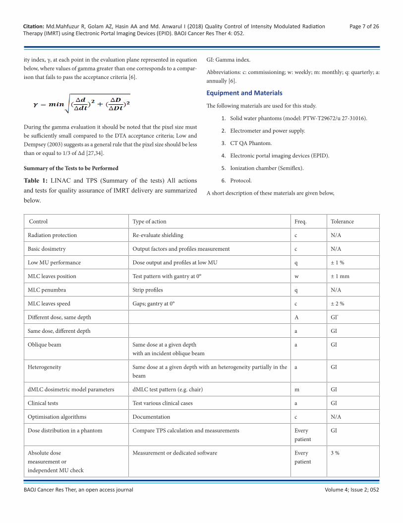
Table 1: LINAC and TPS (Summary of the tests) All actions and tests for quality assurance of IMRT delivery are summarized below.
GI: Gamma index.
Abbreviations: c: commissioning; w: weekly; m: monthly; q: quarterly; a: annually [6].
Equipment and Materials
The following materials are used for this study.
1. Solid water phantoms (model: PTW-T29672/u 27-31016).
2. Electrometer and power supply.
3. CT QA Phantom.
4. Electronic portal imaging devices (EPID).
5. Ionization chamber (Semiflex).
6. Protocol.
A short description of these materials are given below,
Control Type of action Freq. Tolerance
Radiation protection Re-evaluate shielding c N/A
Basic dosimetry Output factors and profiles measurement c N/A
Low MU performance Dose output and profiles at low MU q ± 1 %
MLC leaves position Test pattern with gantry at 0° w ± 1 mm
MLC penumbra Strip profiles q N/A
MLC leaves speed Gaps; gantry at 0° c ± 2 %
Different dose, same depth A GI*
Same dose, different depth a GI
Oblique beam Same dose at a given depthwith an incident oblique beam
a GI
Heterogeneity Same dose at a given depth with an heterogeneity partially in the beam
a GI
dMLC dosimetric model parameters dMLC test pattern (e.g. chair) m GI
Clinical tests Test various clinical cases a GI
Optimisation algorithms Documentation c N/A
Dose distribution in a phantom Compare TPS calculation and measurements Everypatient
GI
Absolute dosemeasurement orindependent MU check
Measurement or dedicated software Everypatient
3 %
Volume 4; Issue 2; 052
Page 8 of 26Citation: Md.Mahfuzur R, Golam AZ, Hasin AA and Md. Anwarul I (2018) Quality Control of Intensity Modulated Radiation Therapy (IMRT) using Electronic Portal Imaging Devices (EPID). BAOJ Cancer Res Ther 4: 052.
BAOJ Cancer Res Ther, an open access journal
Solid Water Phantoms
Solid Water phantom makes radiation beam calibration easier than ever. Designed for photon and electron beam calibrations, it eliminates the in-convenience of transporting, setting up and filling water tanks. Carefully molded and accurately machined into standard dimensions, it can help you achieve calibrations within 1% of the true dose. It scatters and at-tenuates diagnostic and radiotherapy range x-rays the same way as wa-ter without the charge storage problems. It can be used for both photon and electron beam calibrations, including relative ionization, depth dose measurements and absolute calibrations without the need for correction and scaling factors. Ionization readings obtained in Solid Water phantoms are virtually the same as those in liquid water for the same depth and ex-posure duration. Although 30 x 30 cm slabs are most widely used and therefore considered to be a standard size, it is also available in various thicknesses in 20 x 20 cm and 40 x 40 cm sizes [35]. Slabs of Solid Water TM 457 (Gammex RMI) material 20×20×5 cm3 in size were used as a phan-tom. The thickness of the slabs allowed for irradiation of the films at a depth of 5 cm or of 10 cm. Full scatter conditions were assured by 5 cm of PMMA material, which was placed under the film [36]. The formulation, manufacture and testing of an epoxy resin-based solid substitute for wa-ter is presented. This “solid water” has radiation characteristics very close volumetrically to those of water. When it is used as a dosimetry phantom in the radiotherapy range, phantom-to-water corrections and density cor-rections are eliminated. Relative transmission measurements have shown that the transmission through 10 cm of solid water is within 0.2% of that through an equal thickness of water for x-ray and gamma rays [37].
Electrometer and Power Supply
An ionization chamber is essentially a capacitor in which leakage current or leakage charge is induced through the action of a radiation beam. The charge or current induced in the chamber are very small and are measured by a very sensitive charge or current measuring device called an electrometer. Electrometers are devices for measuring small current of the order of 10-9A or less. The power supply in ionization chamber/electrometer circuits is either a standalone unit or forms an integral part of the electrometer. It is useful to be able to change the polarity and voltage provided by the power supply, so that the ion collection efficiency and polarity effects can be determined for a particular radiation beam and ionization chamber [38].
Ionization Chamber
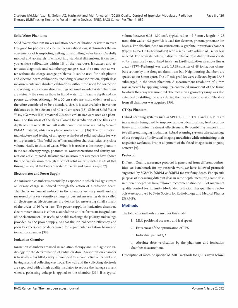
Ionisation chambers are used in radiation therapy and in diagnostic ra-diology for the determination of radiation dose. An ionization chamber is basically a gas filled cavity surrounded by a conductive outer wall and having a central collecting electrode. The wall and the collecting electrode are separated with a high quality insulator to reduce the leakage current when a polarizing voltage is applied to the chamber [39]. Ii is typical
volume between 0.05 -1.00 cm3 , typical radius ~2-7 mm , length~ 4-25 mm , thin walls: ~0.1 g/cm2 .It is used for: electron, photon, proton,or ion beams. For absolute dose measurements, a graphite ionization chamber (type NE–2571 NE–Technology) with a sensitivity volume of 0.6 cm was selected. For accurate determination of relative dose distributions creat-ed by dynamically modulated fields, an LA48 ionization chamber linear array (PTW–Freiburg) was used. LA48 consists of 48 ionization cham-bers set one by one along an aluminium bar. Neighbouring chambers are spaced about 8 mm apart. The off-axis profi les were collected by an LA48 submerged in the water phantom. A measurement resolution of 2 mm was achieved by applying computer-controlled movement of the frame to which the array was mounted. The measuring geometry range was also extended by shifting the array during the measurement session. The data from all chambers was acquired [36].
CT QA Phantom
Hybrid scanning systems such as SPECT/CT, PET/CT and CT/MRI are increasingly being used to improve tumour identification, treatment de-livery and monitor treatment effectiveness. By combining images from two different imaging modalities, hybrid scanning systems take advantage of the strengths of individual imaging modalities while minimizing their respective weakness. Proper alignment of the fused images is an ongoing concern [9].
Protocol
Different Quality assurance protocol is generated from different author-ities. As benchmark for my research work we have followed protocols suggested by SGSMP, SSRPM & SSRFM for verifying doses. For specific purpose of measuring different dose in same depth, measuring same dose in different depth we have followed recommendation no 15 of manual of quality control for Intensity Modulated radiation therapy. These proto-cols were approved by Swiss Society for Radiobiology and Medical Physics (SSRMP).
Methods
The following methods are used for this study.
1. MLC positional accuracy and leaf speed.
2. Extracness of the optimization of TPS.
3. Individual patient QA
4. Absolute dose verification by the phantoms and ionization chamber measurement.
Description of machine specific of IMRT methods for QC is given below:
Volume 4; Issue 2; 052
Page 9 of 26Citation: Md.Mahfuzur R, Golam AZ, Hasin AA and Md. Anwarul I (2018) Quality Control of Intensity Modulated Radiation Therapy (IMRT) using Electronic Portal Imaging Devices (EPID). BAOJ Cancer Res Ther 4: 052.
BAOJ Cancer Res Ther, an open access journal
Procedures Verification of MLC Positional Accuracy and Leaf Speed
According to Varian Medical System provided “DMLC QA test patterns and procedures” have been fixed by the Gantry to 0° Varian scale (0° IEC scale) and the collimator to 0° Varian scale (0° IEC scale). Then source to surface distance (SSD) was kept at 100 cm and the crosshairs was marked above and below and to the right and left of the isocenter with small but detectable pinpricks. Then 1A, 1B and1C each test was loaded into the MLC controller by using the stand-alone MLC workstation program for Picket Fence test [Test: 1] and synchronized segmented stripes [Test: 2]. In Test: 1 the match-lines between the 5cm wide fields were straight and approximately equal in intensity and in Test: 2 the match-lines between the 4 cm wide fields were straight and approximately equal in intensity. Both tests have been performed by using the EPID (Electronic portal imaging device). This study used an aSi-based EPID (aS1000, Varian Medical Systems, Palo Alto, CA) attached to a Varian Clinac-2300CD, Model-DHX Linear accelerator (Varian Medical Systems, Palo Alto, CA, USA). The aS500EPID (for Picket Fence and Synchronized Segmented Stripes) has used for each test. The highest dose rate (600 MU/Min) that is normally used for clinical IMRT cases. Stripes Picket Fence and Synchronized Segmented Stripes test pattern are given below:
Table 2: Picket Fence test
Table 3: Synchronized Segmented Stripes test
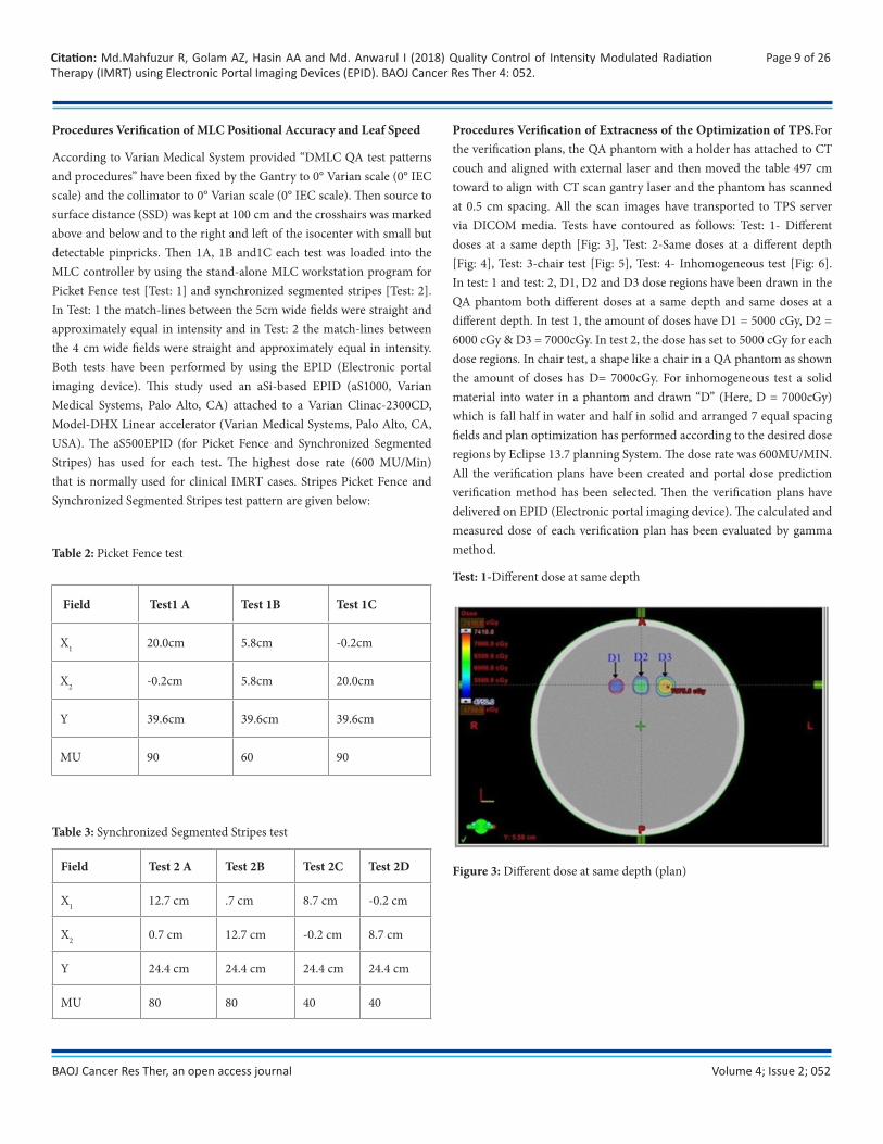
Procedures Verification of Extracness of the Optimization of TPS.For the verification plans, the QA phantom with a holder has attached to CT couch and aligned with external laser and then moved the table 497 cm toward to align with CT scan gantry laser and the phantom has scanned at 0.5 cm spacing. All the scan images have transported to TPS server via DICOM media. Tests have contoured as follows: Test: 1- Different doses at a same depth [Fig: 3], Test: 2-Same doses at a different depth [Fig: 4], Test: 3-chair test [Fig: 5], Test: 4- Inhomogeneous test [Fig: 6]. In test: 1 and test: 2, D1, D2 and D3 dose regions have been drawn in the QA phantom both different doses at a same depth and same doses at a different depth. In test 1, the amount of doses have D1 = 5000 cGy, D2 = 6000 cGy & D3 = 7000cGy. In test 2, the dose has set to 5000 cGy for each dose regions. In chair test, a shape like a chair in a QA phantom as shown the amount of doses has D= 7000cGy. For inhomogeneous test a solid material into water in a phantom and drawn “D” (Here, D = 7000cGy) which is fall half in water and half in solid and arranged 7 equal spacing fields and plan optimization has performed according to the desired dose regions by Eclipse 13.7 planning System. The dose rate was 600MU/MIN. All the verification plans have been created and portal dose prediction verification method has been selected. Then the verification plans have delivered on EPID (Electronic portal imaging device). The calculated and measured dose of each verification plan has been evaluated by gamma method.
Test: 1-Different dose at same depth
Figure 3: Different dose at same depth (plan)
Field Test1 A Test 1B Test 1C
X1 20.0cm 5.8cm -0.2cm
X2 -0.2cm 5.8cm 20.0cm
Y 39.6cm 39.6cm 39.6cm
MU 90 60 90
Field Test 2 A Test 2B Test 2C Test 2D
X1 12.7 cm .7 cm 8.7 cm -0.2 cm
X2 0.7 cm 12.7 cm -0.2 cm 8.7 cm
Y 24.4 cm 24.4 cm 24.4 cm 24.4 cm
MU 80 80 40 40
Volume 4; Issue 2; 052
Page 10 of 26Citation: Md.Mahfuzur R, Golam AZ, Hasin AA and Md. Anwarul I (2018) Quality Control of Intensity Modulated Radiation Therapy (IMRT) using Electronic Portal Imaging Devices (EPID). BAOJ Cancer Res Ther 4: 052.
BAOJ Cancer Res Ther, an open access journal
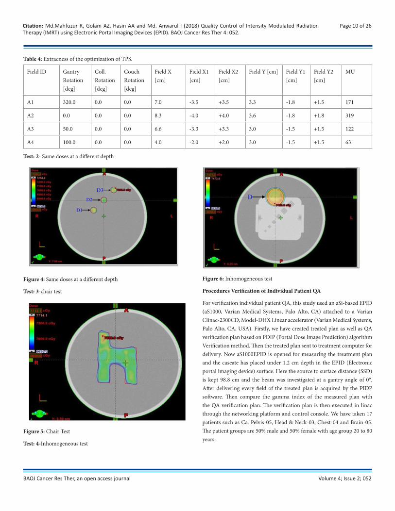
Table 4: Extracness of the optimization of TPS.
Test: 2- Same doses at a different depth
Figure 4: Same doses at a different depth
Test: 3-chair test
Figure 5: Chair Test
Test: 4-Inhomogeneous test
Figure 6: Inhomogeneous test
Procedures Verification of Individual Patient QA
For verification individual patient QA, this study used an aSi-based EPID (aS1000, Varian Medical Systems, Palo Alto, CA) attached to a Varian Clinac-2300CD, Model-DHX Linear accelerator (Varian Medical Systems, Palo Alto, CA, USA). Firstly, we have created treated plan as well as QA verification plan based on PDIP (Portal Dose Image Prediction) algorithm Verification method. Then the treated plan sent to treatment computer for delivery. Now aS1000EPID is opened for measuring the treatment plan and the caseate has placed under 1.2 cm depth in the EPID (Electronic portal imaging device) surface. Here the source to surface distance (SSD) is kept 98.8 cm and the beam was investigated at a gantry angle of 0°. After delivering every field of the treated plan is acquired by the PIDP software. Then compare the gamma index of the measured plan with the QA verification plan. The verification plan is then executed in linac through the networking platform and control console. We have taken 17 patients such as Ca. Pelvis-05, Head & Neck-03, Chest-04 and Brain-05. The patient groups are 50% male and 50% female with age group 20 to 80 years.
Field ID Gantry Rotation [deg]
Coll. Rotation [deg]
Couch Rotation [deg]
Field X [cm]
Field X1 [cm]
Field X2 [cm]
Field Y [cm] Field Y1 [cm]
Field Y2 [cm]
MU
A1 320.0 0.0 0.0 7.0 -3.5 +3.5 3.3 -1.8 +1.5 171
A2 0.0 0.0 0.0 8.3 -4.0 +4.0 3.6 -1.8 +1.8 319
A3 50.0 0.0 0.0 6.6 -3.3 +3.3 3.0 -1.5 +1.5 122
A4 100.0 0.0 0.0 4.0 -2.0 +2.0 3.0 -1.5 +1.5 63
Volume 4; Issue 2; 052
Page 11 of 26Citation: Md.Mahfuzur R, Golam AZ, Hasin AA and Md. Anwarul I (2018) Quality Control of Intensity Modulated Radiation Therapy (IMRT) using Electronic Portal Imaging Devices (EPID). BAOJ Cancer Res Ther 4: 052.
BAOJ Cancer Res Ther, an open access journal
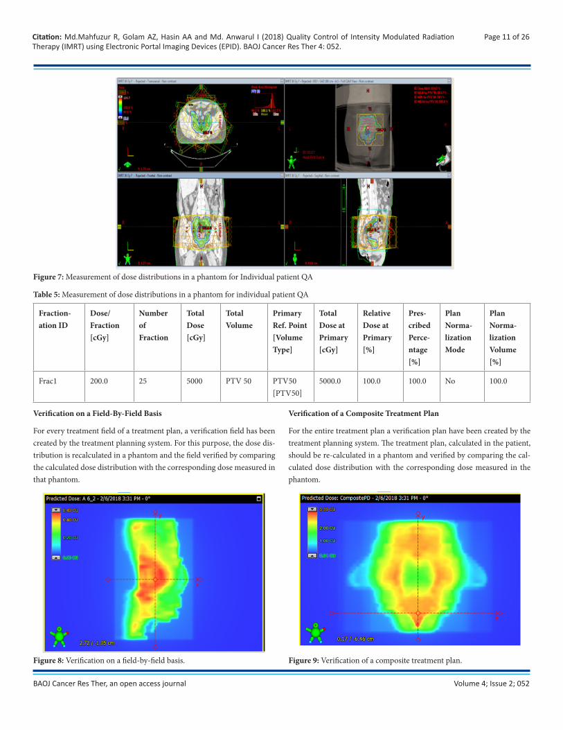
Verification on a Field-By-Field Basis
For every treatment field of a treatment plan, a verification field has been created by the treatment planning system. For this purpose, the dose dis-tribution is recalculated in a phantom and the field verified by comparing the calculated dose distribution with the corresponding dose measured in that phantom.
Fraction-ation ID
Dose/ Fraction [cGy]
Number of Fraction
Total Dose [cGy]
Total Volume
Primary Ref. Point [Volume Type]
Total Dose at Primary [cGy]
Relative Dose at Primary [%]
Pres-cribed Perce-ntage [%]
Plan Norma-lization Mode
Plan Norma-lization Volume [%]
Frac1 200.0 25 5000 PTV 50 PTV50 [PTV50]
5000.0 100.0 100.0 No 100.0
Figure 7: Measurement of dose distributions in a phantom for Individual patient QA
Table 5: Measurement of dose distributions in a phantom for individual patient QA
Verification of a Composite Treatment Plan
For the entire treatment plan a verification plan have been created by the treatment planning system. The treatment plan, calculated in the patient, should be re-calculated in a phantom and verified by comparing the cal-culated dose distribution with the corresponding dose measured in the phantom.
Figure 8: Verification on a field-by-field basis. Figure 9: Verification of a composite treatment plan.
Volume 4; Issue 2; 052
Page 12 of 26Citation: Md.Mahfuzur R, Golam AZ, Hasin AA and Md. Anwarul I (2018) Quality Control of Intensity Modulated Radiation Therapy (IMRT) using Electronic Portal Imaging Devices (EPID). BAOJ Cancer Res Ther 4: 052.
BAOJ Cancer Res Ther, an open access journal
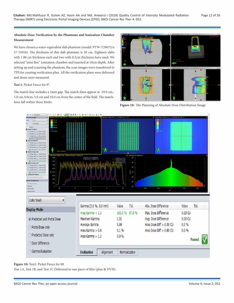
Absolute Dose Verification by the Phantoms and Ionization Chamber Measurement
We have chosen a water-equivalent slab phantom (model: PTW-T29672/u 27-31016). The thickness of this slab phantom is 20 cm. Eighteen slabs with 1.00 cm thickness each and two with 0.5cm thickness have used. We selected “semi flex” ionization chamber and inserted at 10cm depth. After setting up and scanning the phantom, the scan images were transferred to TPS for creating verification plan. All the verification plans were delivered and doses were measured.
Test 1: Picket Fence for 00.
The match-line includes a 1mm gap. The match-lines appear at -10.0 cm,-5.0 cm, 0.0cm, 5.0 cm and 10.0 cm from the center of the field. The match-lines fall within these limits.
Figure 10: The Planning of Absolute Dose Distribution Image
Figure 10: Test1: Picket Fence for 00 Test 1A, Test 1B, and Test 1C Delivered to one piece of film (plan & DVH).
Volume 4; Issue 2; 052
Page 13 of 26Citation: Md.Mahfuzur R, Golam AZ, Hasin AA and Md. Anwarul I (2018) Quality Control of Intensity Modulated Radiation Therapy (IMRT) using Electronic Portal Imaging Devices (EPID). BAOJ Cancer Res Ther 4: 052.
BAOJ Cancer Res Ther, an open access journal
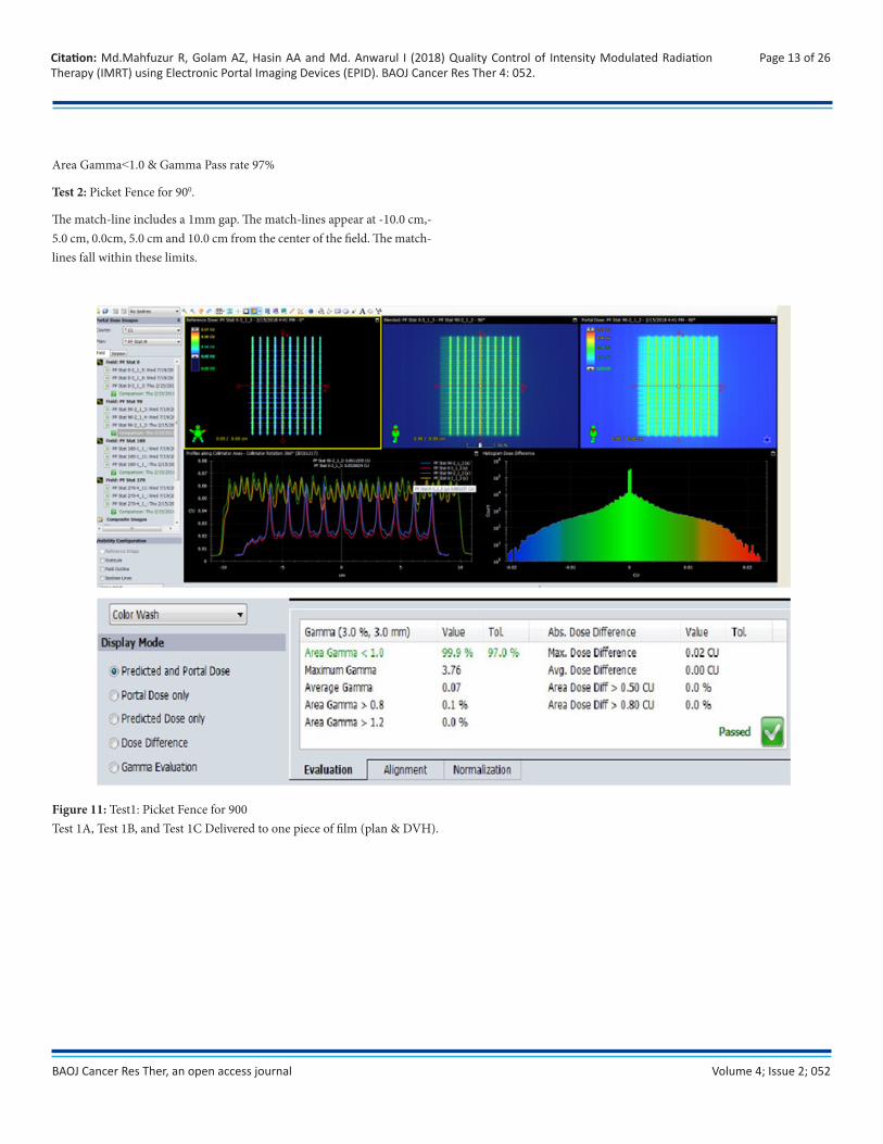
Area Gamma˂1.0 & Gamma Pass rate 97%
Test 2: Picket Fence for 900.
The match-line includes a 1mm gap. The match-lines appear at -10.0 cm,-5.0 cm, 0.0cm, 5.0 cm and 10.0 cm from the center of the field. The match-lines fall within these limits.
Figure 11: Test1: Picket Fence for 900Test 1A, Test 1B, and Test 1C Delivered to one piece of film (plan & DVH).
Volume 4; Issue 2; 052
Page 14 of 26Citation: Md.Mahfuzur R, Golam AZ, Hasin AA and Md. Anwarul I (2018) Quality Control of Intensity Modulated Radiation Therapy (IMRT) using Electronic Portal Imaging Devices (EPID). BAOJ Cancer Res Ther 4: 052.
BAOJ Cancer Res Ther, an open access journal
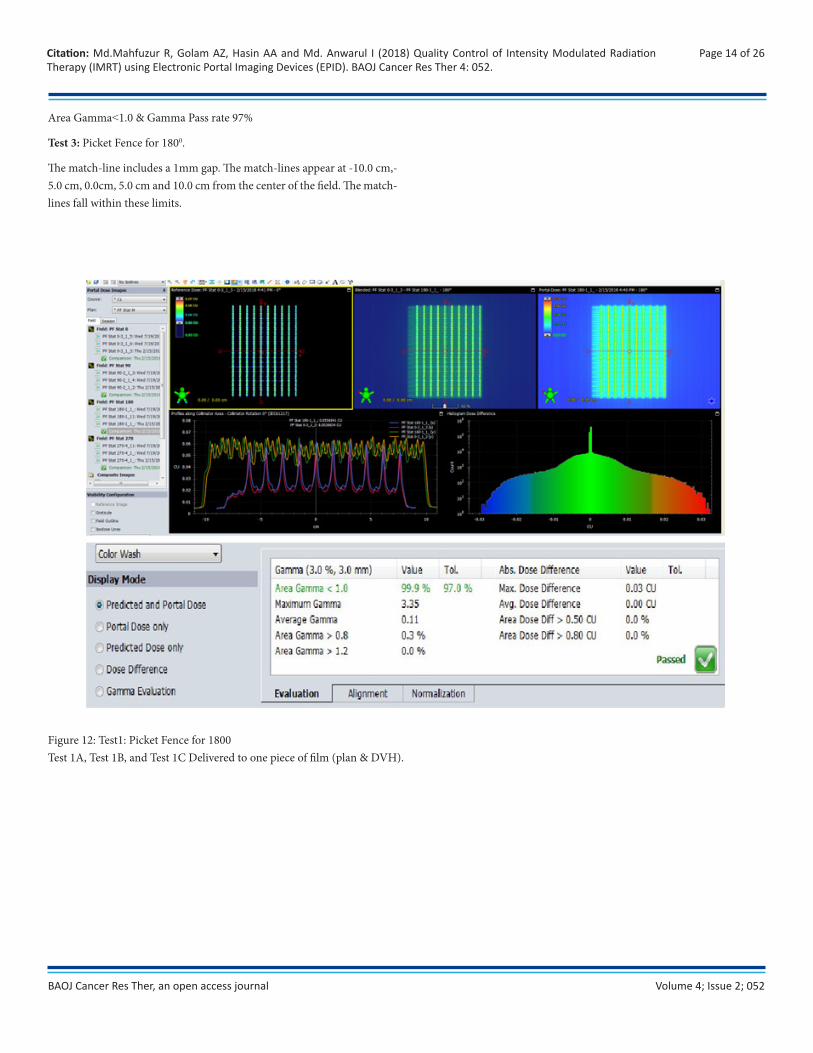
Area Gamma˂1.0 & Gamma Pass rate 97%
Test 3: Picket Fence for 1800.
The match-line includes a 1mm gap. The match-lines appear at -10.0 cm,-5.0 cm, 0.0cm, 5.0 cm and 10.0 cm from the center of the field. The match-lines fall within these limits.
Figure 12: Test1: Picket Fence for 1800Test 1A, Test 1B, and Test 1C Delivered to one piece of film (plan & DVH).
Volume 4; Issue 2; 052
Page 15 of 26Citation: Md.Mahfuzur R, Golam AZ, Hasin AA and Md. Anwarul I (2018) Quality Control of Intensity Modulated Radiation Therapy (IMRT) using Electronic Portal Imaging Devices (EPID). BAOJ Cancer Res Ther 4: 052.
BAOJ Cancer Res Ther, an open access journal
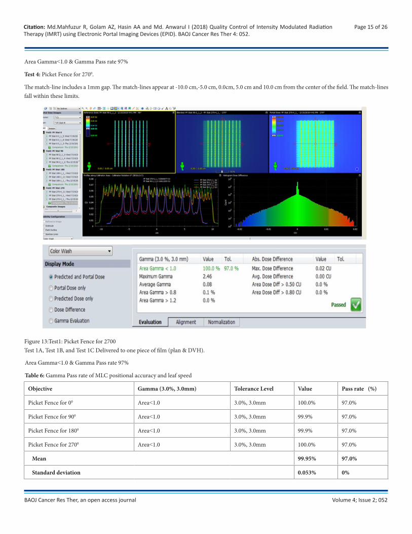
Area Gamma˂1.0 & Gamma Pass rate 97%
Test 4: Picket Fence for 2700.
The match-line includes a 1mm gap. The match-lines appear at -10.0 cm,-5.0 cm, 0.0cm, 5.0 cm and 10.0 cm from the center of the field. The match-lines fall within these limits.
Figure 13:Test1: Picket Fence for 2700Test 1A, Test 1B, and Test 1C Delivered to one piece of film (plan & DVH).
Objective Gamma (3.0%, 3.0mm) Tolerance Level Value Pass rate (%)
Picket Fence for 00 Area˂1.0 3.0%, 3.0mm 100.0% 97.0%
Picket Fence for 900 Area˂1.0 3.0%, 3.0mm 99.9% 97.0%
Picket Fence for 1800 Area˂1.0 3.0%, 3.0mm 99.9% 97.0%
Picket Fence for 2700 Area˂1.0 3.0%, 3.0mm 100.0% 97.0%
Mean 99.95% 97.0%
Standard deviation 0.053% 0%
Area Gamma˂1.0 & Gamma Pass rate 97%
Table 6: Gamma Pass rate of MLC positional accuracy and leaf speed
Volume 4; Issue 2; 052
Page 16 of 26Citation: Md.Mahfuzur R, Golam AZ, Hasin AA and Md. Anwarul I (2018) Quality Control of Intensity Modulated Radiation Therapy (IMRT) using Electronic Portal Imaging Devices (EPID). BAOJ Cancer Res Ther 4: 052.
BAOJ Cancer Res Ther, an open access journal
Test 5: Synchronized Segmented Strips
The match-lines appear at -12.0 cm,-8.0 cm,-4.0 cm, 0.0 cm, 4.0 cm, 8.0 cm and 12.0 cm from the center of the field. Intensity of all the exposed stripes is uniform.
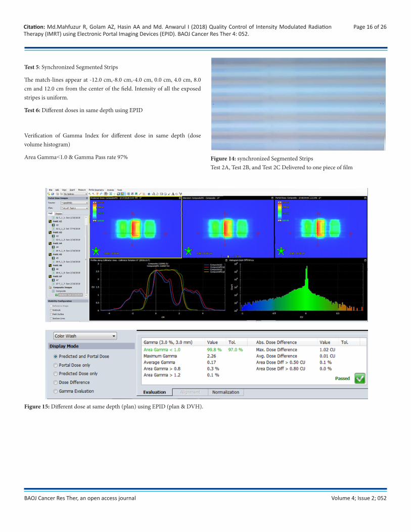
Test 6: Different doses in same depth using EPID
Verification of Gamma Index for different dose in same depth (dose volume histogram)
Area Gamma˂1.0 & Gamma Pass rate 97% Figure 14: synchronized Segmented StripsTest 2A, Test 2B, and Test 2C Delivered to one piece of film
Figure 15: Different dose at same depth (plan) using EPID (plan & DVH).
Volume 4; Issue 2; 052
Page 17 of 26Citation: Md.Mahfuzur R, Golam AZ, Hasin AA and Md. Anwarul I (2018) Quality Control of Intensity Modulated Radiation Therapy (IMRT) using Electronic Portal Imaging Devices (EPID). BAOJ Cancer Res Ther 4: 052.
BAOJ Cancer Res Ther, an open access journal
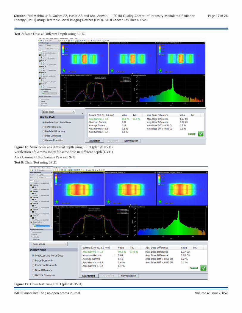
Test 7: Same Dose at Different Depth using EPID.
Figure 16: Same doses at a different depth using EPID (plan & DVH).Verification of Gamma Index for same dose in different depth (DVH)Area Gamma˂1.0 & Gamma Pass rate 97% Test 8: Chair Test using EPID.
Figure 17: Chair test using EPID (plan & DVH).
Volume 4; Issue 2; 052
Page 18 of 26Citation: Md.Mahfuzur R, Golam AZ, Hasin AA and Md. Anwarul I (2018) Quality Control of Intensity Modulated Radiation Therapy (IMRT) using Electronic Portal Imaging Devices (EPID). BAOJ Cancer Res Ther 4: 052.
BAOJ Cancer Res Ther, an open access journal
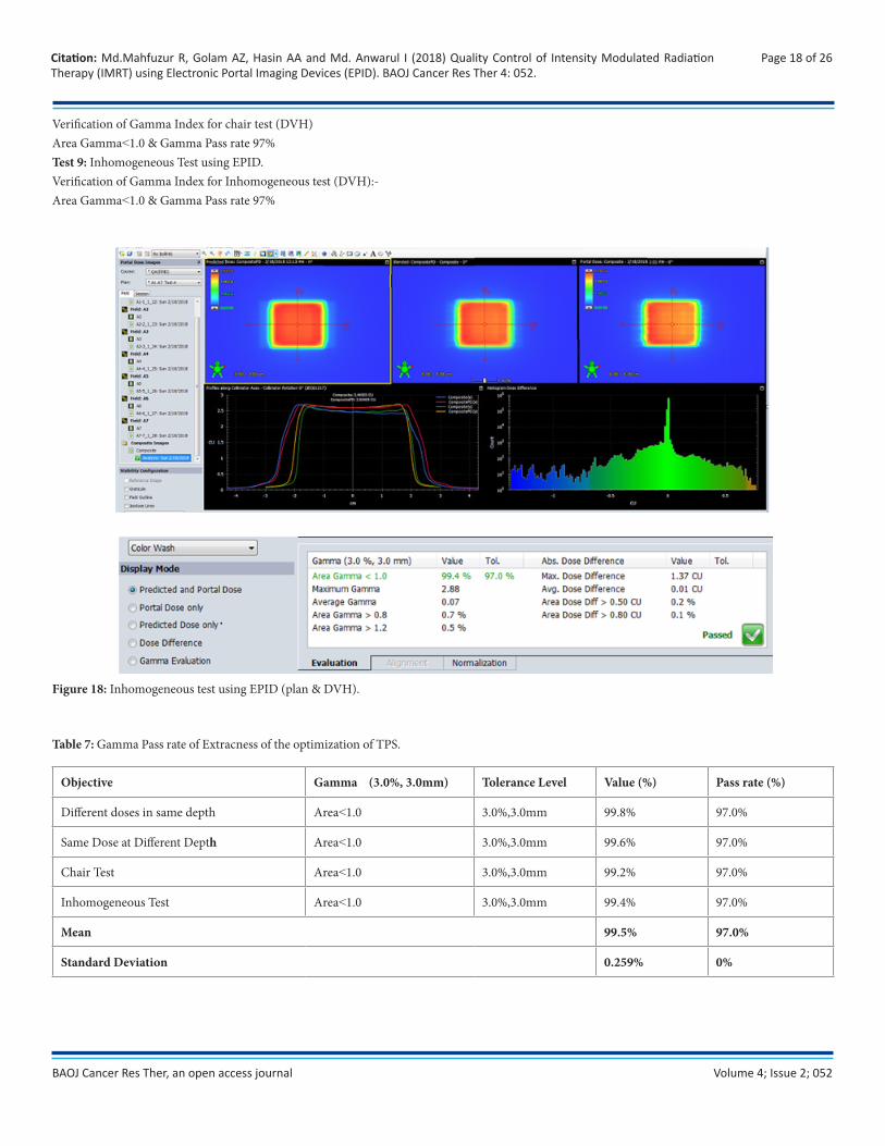
Verification of Gamma Index for chair test (DVH)Area Gamma˂1.0 & Gamma Pass rate 97% Test 9: Inhomogeneous Test using EPID.Verification of Gamma Index for Inhomogeneous test (DVH):-Area Gamma˂1.0 & Gamma Pass rate 97%
Figure 18: Inhomogeneous test using EPID (plan & DVH).
Table 7: Gamma Pass rate of Extracness of the optimization of TPS.
Objective Gamma (3.0%, 3.0mm) Tolerance Level Value (%) Pass rate (%)
Different doses in same depth Area˂1.0 3.0%,3.0mm 99.8% 97.0%
Same Dose at Different Depth Area˂1.0 3.0%,3.0mm 99.6% 97.0%
Chair Test Area˂1.0 3.0%,3.0mm 99.2% 97.0%
Inhomogeneous Test Area˂1.0 3.0%,3.0mm 99.4% 97.0%
Mean 99.5% 97.0%
Standard Deviation 0.259% 0%
Volume 4; Issue 2; 052
Page 19 of 26Citation: Md.Mahfuzur R, Golam AZ, Hasin AA and Md. Anwarul I (2018) Quality Control of Intensity Modulated Radiation Therapy (IMRT) using Electronic Portal Imaging Devices (EPID). BAOJ Cancer Res Ther 4: 052.
BAOJ Cancer Res Ther, an open access journal
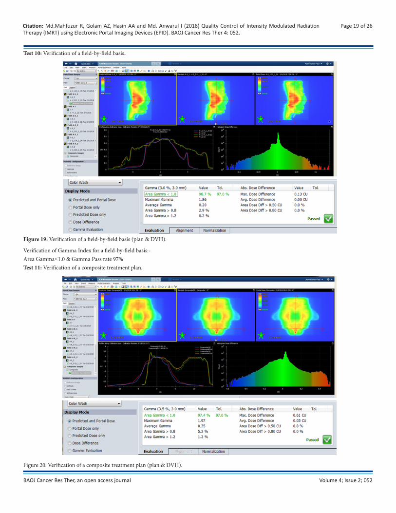
Test 10: Verification of a field-by-field basis.
Figure 19: Verification of a field-by-field basis (plan & DVH).
Verification of Gamma Index for a field-by-field basis:-Area Gamma˂1.0 & Gamma Pass rate 97% Test 11: Verification of a composite treatment plan.
Figure 20: Verification of a composite treatment plan (plan & DVH).
Volume 4; Issue 2; 052
Page 20 of 26Citation: Md.Mahfuzur R, Golam AZ, Hasin AA and Md. Anwarul I (2018) Quality Control of Intensity Modulated Radiation Therapy (IMRT) using Electronic Portal Imaging Devices (EPID). BAOJ Cancer Res Ther 4: 052.
BAOJ Cancer Res Ther, an open access journal
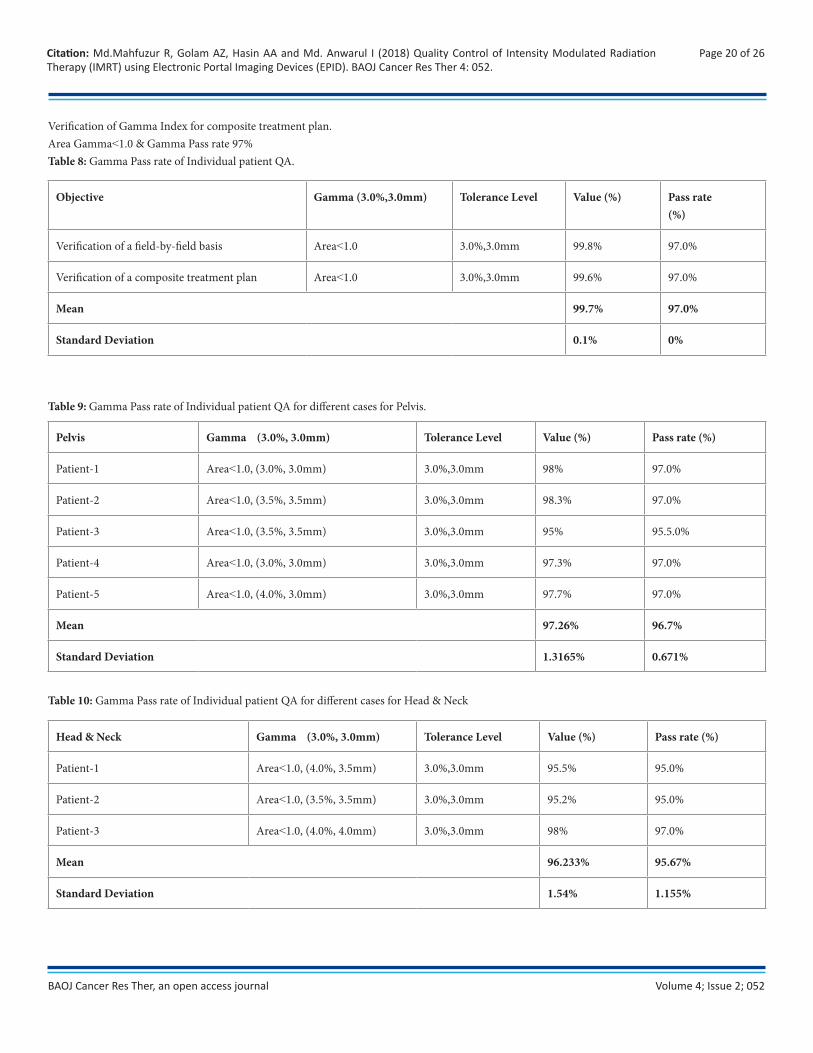
Verification of Gamma Index for composite treatment plan.Area Gamma˂1.0 & Gamma Pass rate 97% Table 8: Gamma Pass rate of Individual patient QA.
Objective Gamma (3.0%,3.0mm) Tolerance Level Value (%) Pass rate(%)
Verification of a field-by-field basis Area˂1.0 3.0%,3.0mm 99.8% 97.0%
Verification of a composite treatment plan Area˂1.0 3.0%,3.0mm 99.6% 97.0%
Mean 99.7% 97.0%
Standard Deviation 0.1% 0%
Table 9: Gamma Pass rate of Individual patient QA for different cases for Pelvis.
Pelvis Gamma (3.0%, 3.0mm) Tolerance Level Value (%) Pass rate (%)
Patient-1 Area˂1.0, (3.0%, 3.0mm) 3.0%,3.0mm 98% 97.0%
Patient-2 Area˂1.0, (3.5%, 3.5mm) 3.0%,3.0mm 98.3% 97.0%
Patient-3 Area˂1.0, (3.5%, 3.5mm) 3.0%,3.0mm 95% 95.5.0%
Patient-4 Area˂1.0, (3.0%, 3.0mm) 3.0%,3.0mm 97.3% 97.0%
Patient-5 Area˂1.0, (4.0%, 3.0mm) 3.0%,3.0mm 97.7% 97.0%
Mean 97.26% 96.7%
Standard Deviation 1.3165% 0.671%
Table 10: Gamma Pass rate of Individual patient QA for different cases for Head & Neck
Head & Neck Gamma (3.0%, 3.0mm) Tolerance Level Value (%) Pass rate (%)
Patient-1 Area˂1.0, (4.0%, 3.5mm) 3.0%,3.0mm 95.5% 95.0%
Patient-2 Area˂1.0, (3.5%, 3.5mm) 3.0%,3.0mm 95.2% 95.0%
Patient-3 Area˂1.0, (4.0%, 4.0mm) 3.0%,3.0mm 98% 97.0%
Mean 96.233% 95.67%
Standard Deviation 1.54% 1.155%
Volume 4; Issue 2; 052
Page 21 of 26Citation: Md.Mahfuzur R, Golam AZ, Hasin AA and Md. Anwarul I (2018) Quality Control of Intensity Modulated Radiation Therapy (IMRT) using Electronic Portal Imaging Devices (EPID). BAOJ Cancer Res Ther 4: 052.
BAOJ Cancer Res Ther, an open access journal
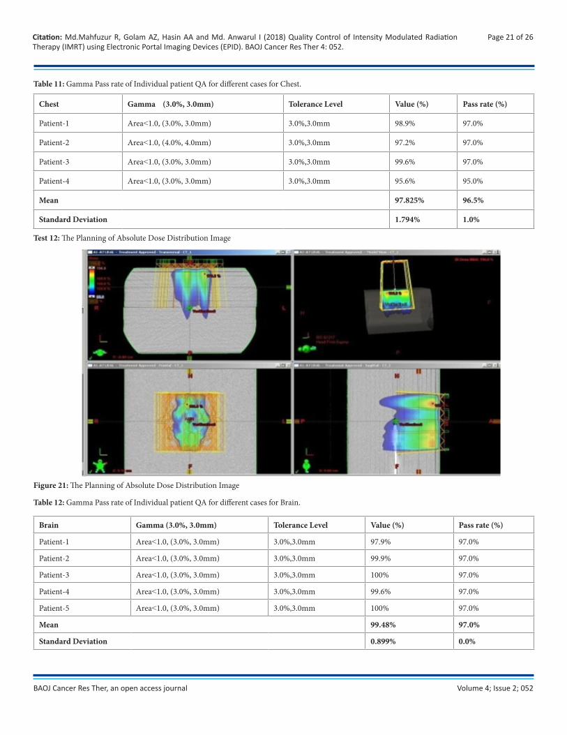
Table 11: Gamma Pass rate of Individual patient QA for different cases for Chest.
Chest Gamma (3.0%, 3.0mm) Tolerance Level Value (%) Pass rate (%)
Patient-1 Area˂1.0, (3.0%, 3.0mm) 3.0%,3.0mm 98.9% 97.0%
Patient-2 Area˂1.0, (4.0%, 4.0mm) 3.0%,3.0mm 97.2% 97.0%
Patient-3 Area˂1.0, (3.0%, 3.0mm) 3.0%,3.0mm 99.6% 97.0%
Patient-4 Area˂1.0, (3.0%, 3.0mm) 3.0%,3.0mm 95.6% 95.0%
Mean 97.825% 96.5%
Standard Deviation 1.794% 1.0%
Test 12: The Planning of Absolute Dose Distribution Image
Figure 21: The Planning of Absolute Dose Distribution Image
Table 12: Gamma Pass rate of Individual patient QA for different cases for Brain.
Brain Gamma (3.0%, 3.0mm) Tolerance Level Value (%) Pass rate (%)
Patient-1 Area˂1.0, (3.0%, 3.0mm) 3.0%,3.0mm 97.9% 97.0%
Patient-2 Area˂1.0, (3.0%, 3.0mm) 3.0%,3.0mm 99.9% 97.0%
Patient-3 Area˂1.0, (3.0%, 3.0mm) 3.0%,3.0mm 100% 97.0%
Patient-4 Area˂1.0, (3.0%, 3.0mm) 3.0%,3.0mm 99.6% 97.0%
Patient-5 Area˂1.0, (3.0%, 3.0mm) 3.0%,3.0mm 100% 97.0%
Mean 99.48% 97.0%
Standard Deviation 0.899% 0.0%
Volume 4; Issue 2; 052
Page 22 of 26Citation: Md.Mahfuzur R, Golam AZ, Hasin AA and Md. Anwarul I (2018) Quality Control of Intensity Modulated Radiation Therapy (IMRT) using Electronic Portal Imaging Devices (EPID). BAOJ Cancer Res Ther 4: 052.
BAOJ Cancer Res Ther, an open access journal
Discussion
The overall Quality Control of Intensity Modulated Radiotherapy was performed in the Square Hospital Limited according to Quality Control of Intensity Modulated Radiation Therapy Protocol of the Swiss Society for Radiology and Medical Physics (SSRMP), Member of the European Federation of Organization for Medical Physics (EFOMP) and the International Organization for Medical Physics (IOMP).
Quality control (QC) is introduced at important steps of process with the purpose of prohibiting errors to continue through the process and thus avoiding an unwanted erroneous irradiation of the patient. A comprehensive quality assurance programmed must be in place before IMRT because quality assurance program is used clinically to ensure accurate IMRT dose delivery. This programmed must include standard verification of linac radiation output as well as tests of the dynamic MLC positioning and movement. A good approach is to perform a subset of the commissioning tests on a regular basis and to keep a record of all test results for periodic inspections.
The Quality Control of IMRT using EPID offers an excellent opportunity to optimize the therapeutic ratio in radiation oncology through tumor coverage and sparing normal tissue by appropriate input. Using IMRT, the dose distribution can be tailored to match the tumour’s shape and position, thereby avoiding damage to healthy tissue to a greater extent than previously possible. Traditional planning for IMRT treatment assumes the target area remains in a fixed location for Quality Control of IMRT.
This study was performed only based on the dosimetric tools; EPID for IMRT patient specific QA. Usually many commercial fluence verification tools are available to perform the QA but considering the perspective of Bangladesh only this tools are commonly available in the hospitals. Nowadays portal Dosimetry and 2-Darray verification systems are widely adopted for the patient specific QA due to their excellent dosimetric characteristics and easiness to use. With the introduction of aSi1000 EPID individual field verification can be done very effectively with an excellent spatial resolution.
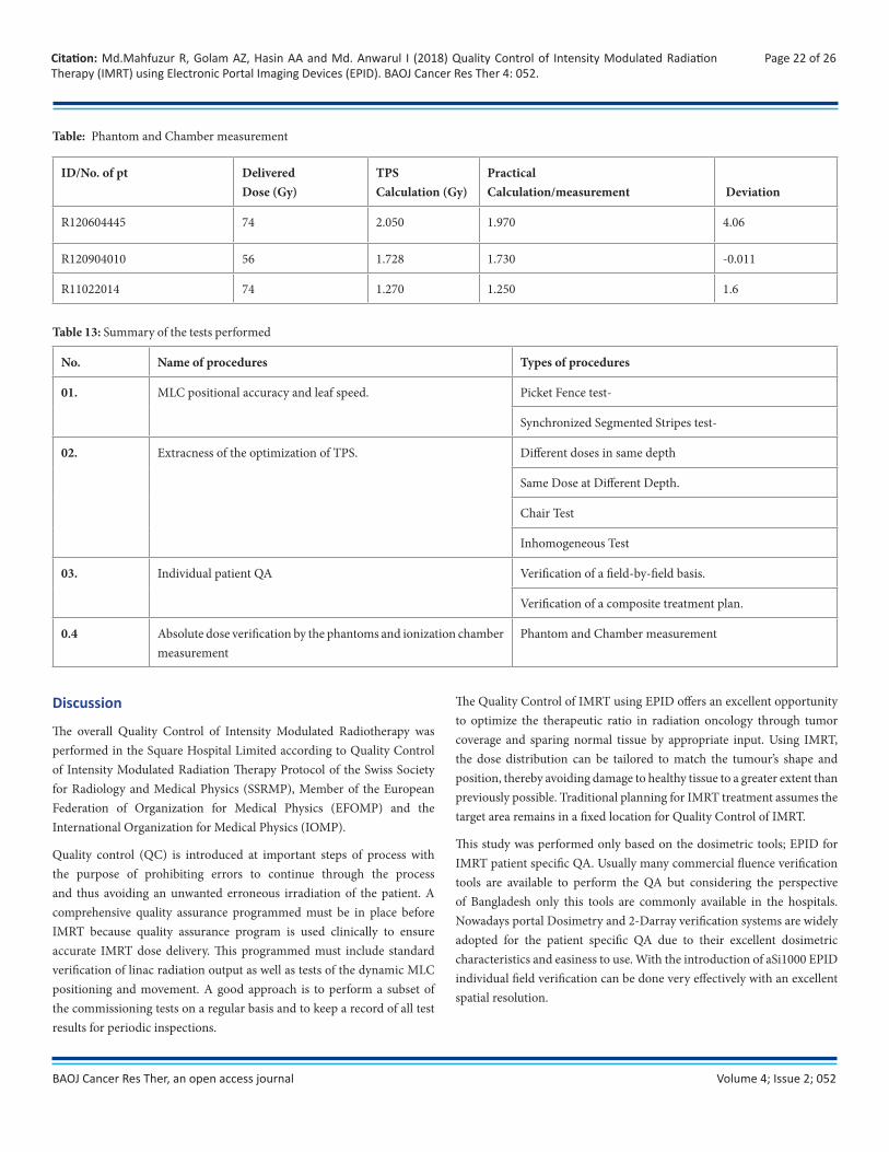
ID/No. of pt DeliveredDose (Gy)
TPSCalculation (Gy)
PracticalCalculation/measurement Deviation
R120604445 74 2.050 1.970 4.06
R120904010 56 1.728 1.730 -0.011
R11022014 74 1.270 1.250 1.6
Table: Phantom and Chamber measurement
Table 13: Summary of the tests performed
No. Name of procedures Types of procedures
01. MLC positional accuracy and leaf speed. Picket Fence test-
Synchronized Segmented Stripes test-
02. Extracness of the optimization of TPS. Different doses in same depth
Same Dose at Different Depth.
Chair Test
Inhomogeneous Test
03. Individual patient QA Verification of a field-by-field basis.
Verification of a composite treatment plan.
0.4 Absolute dose verification by the phantoms and ionization chamber measurement
Phantom and Chamber measurement
Volume 4; Issue 2; 052
Page 23 of 26Citation: Md.Mahfuzur R, Golam AZ, Hasin AA and Md. Anwarul I (2018) Quality Control of Intensity Modulated Radiation Therapy (IMRT) using Electronic Portal Imaging Devices (EPID). BAOJ Cancer Res Ther 4: 052.
BAOJ Cancer Res Ther, an open access journal
We have put emphasis in my thesis work on “Quality Control of Intensity Modulated Radiation Therapy (IMRT) was using EPID” in Radiation Oncology. This study performed the following tests MLC positional accuracy and leaf speed, the relative dosimetric verification (Gamma index), Individual patient QA and absolute dosimetric verification. For MLC leaf positional accuracy and leaf speed, the picket fence and synchronized segmented stripes test pattern (DMLC QA test patterns and procedures) provided by Varian medical system have been used. For each test individual test pattern for 120 MLC have been loaded by stand alone MLC workstation and played. For relative dosimetric verification all the test procedures like different dose in same depth, same dose in different depth, chair test and inhomogeneous test have been performed. All the plans have been verified by measurement with EPID and evaluated by Gamma index. For absolute dose verification all the plans have been delivered and measured by a 0.3 cc Semi Flex chamber along with a PTW solid water phantom. All the tests results were within the tolerance level. Though the Radiation Oncology department of Square Hospital Ltd. is a busy place due to the patient burden, all the quality assurance tests must be carried out accurately. This Quality Control of Intensity Modulated Radiation Therapy (IMRT) using EPID thesis work has a great success.
In the picket Fence test, normally the match-lines were appeared at -15.0 to 15.0 cm from the center of the field. We used aSi1000 EPID. The match-lines appear at -10.0 to 10.0 cm from the center of the field, but, the result was accurate. The match-line includes a 1mm gap. The match-lines fall within these limits. On the other hand, the result of synchronized segmented stripes test was very accurate and the match-lines appear at - 12.0 to 12.0 cm from the center of the field. Usual immobilization support of varian system was used. In absolute dose measurement, we used semiflex ionization chamber because it has sensitive and more suitable for use in water phantom. For relative dosimetric verification all the test procedures like different dose in same depth, same dose in different depth, chair test and inhomogeneous test have been performed & create verification planned and then doses were delivered. For Individual patient QA dose distribution, field in field technique, and composite plan was used. All the plans have been verified by measurement with EPID and evaluated by Gamma index. For absolute dose verification all the plans have been delivered and measurement by a 0.3 cc Semi Flex chamber along with a PTW solid water phantom. Relative and absolute dose verifications have been followed by Protocol of Quality control for Intensity Modulated Radiation Therapy, as in the Recommendation No.15. In picket Fence and Synchronized Segmented Stripes test, match-lines appear at -10.0, -5.0, 0.0, 5.0, 10.0 and -12.0, -8.0, -4.0, 0.0, 4.0, 8.0, 12.0 cm respectively from the center of the field The Pass rate of Gamma Index for picket Fence test were 97%, Mean & Standard deviation 99.95% & 0.053%. The Pass rate of Gamma Index for the different dose in same depth, same dose in different depth, chair test and inhomogeneous test were 97.0% & Mean
& Standard deviation 99.5% and 0.259% at the pixel range in -1.00 to 1.00 & 1.00 to 2.00 respectively. Verification of Pass rate of Gamma Index for a field-by-field basis and composite treatment plan test were 99.8& and 99.6% respectively. Calculated and measured absolute dose for three patients were 2.050 & 1.970 (% deviation 4.06), 1.728 & 1.730 (% deviation -0.011) and 1.270 & 1.250 (% deviation 1.6). The result of calculated and measured absolute doses is satisfied the tolerance limit.
All the unperturbed plans had a γ < 1 passing rate of 100% using 3%/3 mm. When using 2%/2mm, the passing rate for all the plans was greater than 97%. The 5 mm systematic MLC errors were detected using 3%/3 mm in the EPID in the IMRT plans. However, the 2 mm systematic errors were difficult to detect using 3%/3 mm; the γ in the region where the errors occurred was increased in comparison to the surrounding area, but was still < 1, and hence would not be detected as a fault. The error was detectable at 2%/2 mm. We have taken 17 patients such as Ca. Pelvis-05, Head & Neck-03, Chest-04 and Brain-05. The patient groups are 50% male and 50% female with age group 20 to 80 years. The passing rate of Gamma. Seventeen cases including five pelvis, three head and neck, four chest, and five brain cases were selected for this study. The gamma passing rates for pelvis cases for IMRT four patients were 97% and one patient 95.5%, head and neck two patients were 95.0 % and one patient 97.0% respectively. Similarly, for brain the gamma passing rate for IMRT were 97.0% and passing rate of chest three patients 97.0% and one patient 95% for IMRT. The criteria for gamma passing were 3%, 3mm for three cases of 17 patients. The gamma analysis showed an average passing rate of 96.47% for all 17 cases.
Wma Declaration of Helsinki – Ethical Principles for Medical Research Involving Human Subjects
To complete our research, we have followed the WMA declaration of Helsinki – Ethical Principles for medical research involving human subjects. Since radiotion is very much harmful for all the human being, we have informed the benefits, side effects and the risks of radiotherapy to the patients firstly. We have followed the radiation safety for the patient as well as the radiotherapy workers.
Conclusion & Limitation
A Quality system is the organizational structure, responsibilities procedures, processes, and resources for implementing QA. The aim of a Quality system in the radiation oncology context is “to provide a formal written scheme to ensure all important aspect of quality assurances in the department are defined, documented understood and put into practice”. This ensures that no quality assurances are inadvertently omitted. A Quality system provides an overall framework for policies, procedure, and tasks. While the framework is formal and comprehensive it should also be flexible to ensure the possibilities of changes and improvement based on regular assessments. The system should provide a structure in
Volume 4; Issue 2; 052
Page 24 of 26Citation: Md.Mahfuzur R, Golam AZ, Hasin AA and Md. Anwarul I (2018) Quality Control of Intensity Modulated Radiation Therapy (IMRT) using Electronic Portal Imaging Devices (EPID). BAOJ Cancer Res Ther 4: 052.
BAOJ Cancer Res Ther, an open access journal
which changes in equipment and techniques can be handled efficiently, smoothly, and safely, not only from technical and treatment perspective but also from the patient perspective. IMRT is a newer technology that introduces new potential for error and into the delivery of radiation therapy. IMRT can be used to improve the care of cancer patients without subjecting them to unnecessary risks. IMRT are relatively inexpensive, portable, save, and real time in nature. For relative dosimetric verification all the test procedures like picket Fence, Synchronized Segmented Stripes, different dose in same depth, same dose in different depth, chair test and inhomogeneous tests, the QC of IMRT is accurate. For IMRT treatment SSRMP, EFOMP and IOMP protocols are appropriate. So, we should maintain the entire quality control program.
Commissioning and quality assurance of dMLC for IMRT application requires considerable time and effort.The positional accuracy of the MLC has a larger impact on delivered dose in IMRT than in conventional 3DCRT, where the MLC defines only the outer border of the beam. Thus, the positional accuracy of the MLC should be evaluated over the full range of leaf travel and carriage motion that will be clinically employed. Leaf speed instability may arise from mechanical or steering problems or also due to the calibration technique employed. It is very important to ensure the MLC positional and leaf speed accuracy before the treatment is delivered in case of IMRT. The goal of this work is to ensure QC before implementing IMRT treatment. This report addresses different tests that should be performed during commissioning, acceptance and quality control of IMRT treatments. This report is an attempt to address some experiment setup and measurements that was followed by Recommendation No.15 from SGSMP. The accuracy and results of those test in this study showed that the quality control of IMRT were perfectly done.
This work is not a fully complete work but help a lost the person who want to complete the Machine Specific QC of IMRT in Bangladesh. From this study on the Machine Specific QC of IMRT at Square Hospital Ltd. in Dhaka. It can conclude that, the absence of preventive maintenance, regularly performed quality control tests and authorized body for regulating the Cancer center use of IMRT in our country are the main reasons behind the degradation of the performance of IMRT machines where only minimum percent of the tested IMRT machines in both governmental and private sectors showed the recommended performance for the all the performed quality control tests. The lake of training in maintaining IMRT Machine equipments lead to the noticeable shortage in the number of expert engineers for maintaining IMRT Machine equipment. The issue of quality control for medical equipment is in general neglected by the ministry of health which can be considered as a main reason behind the lack of quality control culture among most of the Radiographer in the country. This work is to be extended to cover more IMRT machines both in Dhaka Medical college Hospital and other Hospital and to include IMRT machines. The promulgation of the new
nuclear energy act that deals with regulating the use of both ionizing and non-ionizing radiation is expected to enhance the situation as far as the Cancer Center use of IMRT Machine in the country.
There were some limitations in this work, which are discussed here. One limitation of this work was that all the measurements were carried out in a single institute. It is possible that other institutions may find larger differences between IMRT QA. However, the results found here show that it is reasonable for IMRT QA to give comparable results. Further work by other institutions may increase the confidence of this assessment.
In this study, the IMRT verification was carried out using EPID. It can be possible to add more detectors to verify the treatment plans.
Although “Garden fence test” is superior to picket fence test and segmented stripes in some respect we could not do it because of limitation in logistic support.
All the radiotherapy centre should perform the Machine Specific QC of IMRT procedure for delivering the accurate treatment.
References
1. (2017) Intensity Modulated Radiation Therapy (IMRT). Radiologyinfo.org for patient: 1-5.
2. Clifford KS, Chao MD, Apisarnthanarax S, Ozyigit G (2005) Intensity Modulated Radiation therapy. 2nd Edn Philadelphia: Lippincott Williams & Wilkins: 1-27.
3. Jabbari K, Amouheidari A, Babazadeh S (2012) The QC of IMRT for ONCOR Siemens Linear Accelerators using Flim Dosimetry. Iranian Journal of Medical Physics 9(2): 111-125.
4. Ezzell GA, Burmeister JW, Dogan N, LoSasso TJ, Mechalakos JG, et al. (2009) IMRT commissioning: multiple institution planning and dosimetry comparisons, a report from AAPM Task Group 119. Med Phys 36(11): 5359-5373.
5. Ezzell GA, Galvin JM, Low D, Palta JR, Rosen I, et al. (2003) Guidance document on delivery, treatment planning, and clinical implementation of IMRT: report of the IMRT Subcommittee of the AAPM Radiation Therapy Committee. Med Phys 30(8):2089-2115.
6. Swiss Society for Radiology and Medical Physics (SSRMP) (2007) Member of the European Federation of Organization for Medical Physics (EFOMP) and the International Organization for Medical Physics (IOMP).Quality Control of Intensity Modulated Radiation Therapy. Recommendations No.15. ISBN 3 908 125 41 3: 1-14.
7. Dilshad KP. Intensity Modulated Radiation Therapy. University of Calicut.
8. LoSasso T1, Chui CS, Ling CC (1998) Physical and dosimetric aspects of a multileaf Collimation system used in the dynamic

Volume 4; Issue 2; 052
Page 25 of 26Citation: Md.Mahfuzur R, Golam AZ, Hasin AA and Md. Anwarul I (2018) Quality Control of Intensity Modulated Radiation Therapy (IMRT) using Electronic Portal Imaging Devices (EPID). BAOJ Cancer Res Ther 4: 052.
BAOJ Cancer Res Ther, an open access journal
mode for implementing intensity modulated radiotherapy. Med Phys 25(10): 1919-1927.
9. (2001) DMLC QA Test patterns and procedures. VARIAN medical system P/N 10012878-01.
10. Sternick ES (1997) The theory and practice of intensity modulated radiation therapy. Madison WI: Advanced Medical Publishing.
11. Podgorsak EB (2005) Quality Assurance of external beam radiotherapy. In Podgorsak EB, Editor. Radiation Oncology Physics: A handbook for teachers & students, International atomic energy agency: 335-360.
12. Wertz H, Wenz F .Quality assurance (QA) in radiotherapy. Mannheim Medical Center. University of Heidelberg: 1-5.
13. Moran JM, Xia P. QA-QC of IMRT: American Perspective; Chap.11: 131-135.
14. Galvin JM, Ezzell G, Eisbruch A, Yu C, Brain B, et al. (2004) Implementing IMRT in clinical practice: A joint document of the American Society for Therapeutic Radiology and Oncology and the Ame-rican Association of Physicists in Medicine. Int J Radiat Oncol Biol Phys 58(5): 1616-1634.
15. Munro, Dogan N, Glukman et al. (2002) IMRTQA Tools. Med Physics 29(8): 1839-1846.
16. 16. Pasma KL, Dirkx ML, Kroonwijk M, Visser AG, Heijmen BJ (1999) Dosimetric verification of intensity modulated beams produced with dynamic multileaf collimation using an electronic portal imaging device. Med Phys 26(11): 2373-2378.
17. Vieira SC, Dirkx MLP, Pasma KL, Heijmen BJM (2003) Dosimetric verification of X-ray fields with steep dose gradients using an electronic portal imaging device. Phys Med Biol. 48(2): 157-166.
18. Curtin-Savard AJ, Podgorsak EB (1999) Verification of segmented beam delivery using a commercial electronic portal imaging device. Med Phys 26(5): 737-742.
19. Van Esch A, Vanstraelen B, Verstraete J, Kutcher G, Huyskens D (2001) Pretreatment dosimetric verification by means of a liquid-filled electronic portal imaging device during dynamic delivery of intensity modulated treatment fields. Radiother Oncol 60(2): 181-190.
20. Chang J,Mageras GS, Ling CC (2003) Evaluation of rapid dose map acquisition of a scanning liquid-filled ionization chamber electronic portal imaging device. Int J Radiat Oncol Biol Phys 55(5): 1432-1445.
21. El-Mohri Y, Antonuk LE, Yorkston J, Jee KW, Maolinbay M, et al. (1999) Relative dosimetry using active matrix flat-panel imager (AMFPI) technology. Med Phys 26(8): 1530-1541.
22. McCurdy BM, Luchka K, Pistorius S (2001) Dosimetric investigation and portal dose image prediction using an amorphous silicon electronic portal imaging device. Med Phys 28(6): 911-924.
23. Warkentin B, Steciw S, Rathee S, Fallone BG (2003) Dosimetric IMRT verification with a flat-panel EPID. Med Phys 30(12): 3143-3155.
24. Van Esch A, Depuydt T, Huyskens DP (2004) The use of an aSibased EPID for routine absolute dosimetric pre-treatment verification of dynamic IMRT fields. Radiother Oncol 71(2): 223-234.
25. SSRMP (1997) Quality control of treatment planning systems for teletherapy. Recommendations No.7: ISBN 3-908125-23-5.
26. Xing A, Arumugam S, Deshpande S, George A, Vial P, et al. (2015) Evaluation of 3D Gamma index calculation implemented in two commercial dosimetry systems. Journal of Physics: Conference Series 573: 012054-1 - 012054-4.
27. Zhen H et al. (2011) The Benchmark for 3D VMAT QA. Med Phys 38: 5477-89.
28. Low D A, Moran JM, Dempsey JF, Dong L, Oldham M (2011) Dosimetry tools and techniques for IMRT. Med Phys 38(3): 1313-1338.
29. Partridge M, Hesse B-M and Müller L (2002) A performance comparison of direct- and indirectdetection flat-panel imagers. Nuclear Instruments and Methods in Physics Research Section A 484(1-3): 351-363.
30. Depuydt T, Esch AN and Huyskens DP (2002) A quantitative evaluation of IMRT dose distributions: refinement and clinical assessment of the gamma evaluation. Radiotherapy and Oncology 62(3): 309-319.
31. Low D A, Dempsey J F (2003) Evaluation of the gamma dose distribution comparison method. Medical Physics 30(9): 2460-2463.
32. Eric EK, Hanley J, Bayouth J, Yin F, Simon W et al. (2009) Task Group 142 report:Quality assurance of medical accelerators. Medical Physics 36(9): 4197-4212.
33. Nelms B E and Simon J A (2007) A survey on planar IMRT QA analysis. Journal of Applied Clinical Medical Physics 8(3): 2448.
34. Wåhlin Erik (2006) Dosimetric pre-treatment verification with an electronic portal imaging device.
35. CNMC. Solid water phantom material; a best medical company.
36. Chełmiński K, Rostkowska J, Kania M, Bulski W, Gwiazdowska B (2005) Measurement of the sensitometric curves of Kodak EDR2 and X-Omat V films using Enhanced Dynamic Wedges and

Volume 4; Issue 2; 052
Page 26 of 26Citation: Md.Mahfuzur R, Golam AZ, Hasin AA and Md. Anwarul I (2018) Quality Control of Intensity Modulated Radiation Therapy (IMRT) using Electronic Portal Imaging Devices (EPID). BAOJ Cancer Res Ther 4: 052.
BAOJ Cancer Res Ther, an open access journal
Dynamic Multileaf Collimators. Rep Pract Oncol Radiother 10(6): 293-300.
37. (1982) Medical physics research support. U.S.Goverment P.H.S 9(3): 436-441.
38. Podgorsak EB, Andreo P, Seuntjens JP (2005) Calibation of Photon and Electron Beams. Radiation Oncology Physics: A handbook for teachers & students, International atomic energy agency: 249-268.
39. Podgorsak EB (2005) Radiation Dosimeters. Radiation Oncology Physics: A handbook for teachers & students, International atomic energy agency: 64-67.
40. Podgorsak EB (2005) Special procedures and techniques in radiotherapy. In Podgorsak EB, Editor. Radiation Oncology Physics: A handbook for teachers & students, International atomic energy agency: 435-440.
41. Knöös T, Ibbott GS, Thwaites DI, Schreiner LJ, Yi Du, et al. (2015) QA procedures needed for advanced RT techniques and its impact on treatment outcome. 8th International Conference on 3D Radiation Dosimetry (IC3DDose), Sweden Journal of Physics: Conference Series: 573 012001.
42. S Webb (2003) The physical basis of IMRT and inverse planning. The British Journal of Radiology 76(910): 678-689. DOI: 10.1259/bjr/65676879
43. Millie Chu (2006) Robust intensity modulated radiation therapy treatment planning. Section: 2.1, 2.2, 3.1: 11-55.
44. Jatinder RP, Chihray Liu, Jonathan GL (2008) Quality Assurance of Intensity-Modulated Radiation Therapy. International Journal of Radiation Oncology 71(1): S108-S112.
45. Julian M (2012) The importance of accurate treatment planning, delivery and dose verification. Reports of practical oncology and radiotherapy 17(2): 63-65.
46. Rebecca SC (2013) Verification of Intensity Modulated Radiotherapy. Chapter 5: 78-91.
47. Vinall AJ, Williams A J, Currie V E, Vanesch A, Huyskens D (2010) Practical guidelines for routine intensity-modulated radiotherapy verification: pre-treatment verification with portal dosimetry and treatment verification with in vivo dosimetry. The British Journal of Radiology 83(95): 949-957.
48. Hussein M, Adams EJ, Jordan TJ, Clark CH, Nisbet A (2013) A critical evaluation of the PTW 2D-ARRAY seven29 and OCTAVIUS II phantom for IMRT and VMAT verification. J Appl Clin Med Phys 14(6): 4460-4464.
49. Intensity Modulated Radiation Therapy Collaborative Working Group (2001) Intensity modulated therapy: current status and issues of interest. Int J Radiat Oncol Biol Phys 51(4): 880-914.
50. Low D A, Hams W B, Mutic S, Purdy JA (1998) A technique for the quantitative evaluation of dose distributions. Med Phys 25(5): 656-661.
51. Jayesh K, Ganesh T, Suganthi D, Mohan R, Rakesh CJ, et al. (2013) Dosimetric Comparison of aSi1000 EPID and ImatriXX 2-D Array System for Volumetric Modulated Arc and Intensity Modulated Radiotherapy Patient Specific Quality Assurance. International Journal of Physical and Mathematical science 7(3): 393-394.
52. Son J, Baek T, Lee B, Shin D, Park SY, et al. (2015) A comparison of the quality assurance of four dosimetric tools for intensity modulated radiation therapy. Radiol Oncol 49(3): 307-313.
53. Rao M, Yang W, Chen F, Sheng K, Ye J, et al. (2010) Comparison of Elekta VMAT with helical tomotherapy and fixed field IMRT: Plan quality, delivery efficiency and accuracy. Medical Physics 37(3): 1350-1359.
54. Saminathan S, Manickan R, Chandraraj V, Sanjay S (2010) Dosimetric study of 2D ion chamber array matrix for the modern radiotherapy treatment verification. Journal of Applied Clinical Medical Physics 11(2): 3076.