Embed Size (px)
Citation preview

CANbridgeCAN-to-CAN Gateway
USER MANUAL4.01.0120.20000 3.0 en-US ENGLISH

Important User InformationDisclaimerThe information in this document is for informational purposes only. Please inform HMS Networks of anyinaccuracies or omissions found in this document. HMS Networks disclaims any responsibility or liability for anyerrors that may appear in this document.
HMS Networks reserves the right to modify its products in line with its policy of continuous product development.The information in this document shall therefore not be construed as a commitment on the part of HMS Networksand is subject to change without notice. HMS Networks makes no commitment to update or keep current theinformation in this document.
The data, examples and illustrations found in this document are included for illustrative purposes and are onlyintended to help improve understanding of the functionality and handling of the product. In view of the wide rangeof possible applications of the product, and because of the many variables and requirements associated with anyparticular implementation, HMS Networks cannot assume responsibility or liability for actual use based on the data,examples or illustrations included in this document nor for any damages incurred during installation of the product.Those responsible for the use of the product must acquire sufficient knowledge in order to ensure that the productis used correctly in their specific application and that the application meets all performance and safety requirementsincluding any applicable laws, regulations, codes and standards. Further, HMS Networks will under no circumstancesassume liability or responsibility for any problems that may arise as a result from the use of undocumented featuresor functional side effects found outside the documented scope of the product. The effects caused by any direct orindirect use of such aspects of the product are undefined and may include e.g. compatibility issues and stabilityissues.
CANbridge User Manual 4.01.0120.20000 3.0 en-US
CANbridge User Manual 4.01.0120.20000 3.0 en-US
Table of Contents Page
1 User Guide ........................................................................................................................... 31.1 Related Documents ..........................................................................................................3
1.2 Document History ............................................................................................................3
1.3 Conventions....................................................................................................................4
2 Safety Instructions .............................................................................................................. 52.1 Information on EMC .........................................................................................................5
2.2 General Safety Instructions ................................................................................................5
3 Scope of Delivery ................................................................................................................ 5
4 Product Description and Features...................................................................................... 6
5 Installation........................................................................................................................... 75.1 Power Connector .............................................................................................................7
5.2 CAN Connectors...............................................................................................................8
5.3 Configuration Connector ...................................................................................................8
5.4 Ground Connections .........................................................................................................8
6 Configuration....................................................................................................................... 96.1 Starting and Operating the Download Tool CANBcfg ..............................................................9
6.2 Creating the Configuration............................................................................................... 10
6.3 Load Configuration to Device ........................................................................................... 15
6.4 Show Current Configuration............................................................................................. 16
6.5 Standard Configuration ................................................................................................... 16
6.6 Configuration Example .................................................................................................... 17
7 Operation........................................................................................................................... 187.1 Automatic Baud Rate Detection Sequence.......................................................................... 18
7.2 Power LED (PWR)........................................................................................................... 18
7.3 CAN 1/CAN 2 LED........................................................................................................... 19
7.4 COM LED ...................................................................................................................... 19
8 Additional Components .................................................................................................... 198.1 CAN Bus Termination...................................................................................................... 19

CANbridge User Manual 4.01.0120.20000 3.0 en-US
9 Technical Data ................................................................................................................... 20
10 Support/Return Hardware................................................................................................ 2110.1 Support ........................................................................................................................ 21
10.2 Return Hardware ........................................................................................................... 21
11 Disposal.............................................................................................................................. 21
A Regulatory Compliance ..................................................................................................... 23A.1 EMC Compliance (CE) ..................................................................................................... 23
A.2 FCC Compliance Statement .............................................................................................. 23
A.3 Disposal and recycling..................................................................................................... 24

User Guide 3 (26)
1 User GuidePlease read the manual carefully. Make sure you fully understand the manual before using theproduct.
1.1 Related DocumentsDocument AuthorInstallation Guide VCI Driver HMS
1.2 Document HistoryVersion Date Description
2.0 October 2016 Revised and edited in new design.
2.1 June 2019 Layout changes, new disclaimer
3.0 October 2021 Removed obsolete DIN rail device variant
1.2.1 Trademark InformationIxxat® is a registered trademark of HMS Industrial Networks. All other trademarks mentioned inthis document are the property of their respective holders.
CANbridge User Manual 4.01.0120.20000 3.0 en-US

User Guide 4 (26)
1.3 ConventionsInstructions and results are structured as follows:
► instruction 1
► instruction 2
→ result 1
→ result 2
Lists are structured as follows:
• item 1
• item 2
Bold typeface indicates interactive parts such as connectors and switches on the hardware, ormenus and buttons in a graphical user interface.
This font is used to indicate program code and otherkinds of data input/output such as configuration scripts.
This is a cross-reference within this document: Conventions, p. 4
This is an external link (URL): www.hms-networks.com
Safety advice is structured as follows:
Cause of the hazard!
Consequences of not taking remediate action.
How to avoid the hazard.
Safety signs and signalwords are used dependent on the level of the hazard.
This is additional information which may facilitate installation and/or operation.
This instruction must be followed to avoid a risk of reduced functionality and/or damageto the equipment, or to avoid a network security risk.
CautionThis instruction must be followed to avoid a risk of personal injury.
WARNINGThis instruction must be followed to avoid a risk of death or serious injury.
CANbridge User Manual 4.01.0120.20000 3.0 en-US

Safety Instructions 5 (26)
2 Safety Instructions2.1 Information on EMC
Risk of interference to radio and television if used in office or home environment!
Use exclusively included accessories. Use exclusively shielded cables.
Make sure that the shield of the interface is connected with the device plug and the plugon the other side.
► Make sure, that the CAN bus that is connected to the CANbridge has a shielded lead.
► Make sure, that the shield braiding is laid flat on the connector housing.
Shield connections of CAN 1, CAN 2, serial interface RS232 and power supply are connected withone another in the device.
2.2 General Safety Instructions► Protect product from moisture and humidity.
► Protect product from too high or too low temperature (see Technical Data, p. 20).
► Protect product from fire.
► Do not paint the product.
► Do not modify or disassemble the product. Service must be carried out by HMS IndustrialNetworks.
► Store products in dry and dust-free place.
3 Scope of DeliveryIncluded in scope of delivery:
• CANbridge
• User Manual
• CD with download tool CANBcfg.exe and VCI Installation Guide
• configuration cable
• power supply cable
CANbridge User Manual 4.01.0120.20000 3.0 en-US

Product Description and Features 6 (26)
4 Product Description and FeaturesThe CANbridge is a universal, intelligent CAN topology component, that allows the coupling oftwo CAN networks, also with different bit rates or frame formats. CAN messages are received byone network and transmitted in the other network, according to filter and implementation rules.
The CAN messages can be filtered based on CAN identifiers. Certain CAN messages can beforwarded and others discarded. With this mechanisms the bus load can be reduced in theassociated network by transmitting only the messages that are of interest.
The baud rates of the CAN busses are freely configurable. Additionally the CANbridge providesautomatic baud rate detection. To configure the CANbridge a configuration file is used. Theconfiguration is created in ASCII code and loaded on the CANbridge with a download tool via theserial interface.
Features and highlights:
• galvanically isolated
• configuration via serial interface (RS232, optional RS485)
• CAN ID filtering
• aluminium housing
Versions
• Industrial: 2 x CAN high-speed connection (ISO 11898-2)
• Automotive: 2 x CAN high-speed connection (ISO 11898-2)
• Automotive: 1 x CAN high-speed and 1 x CAN low-speed connection (ISO 11898-3)
CANbridge User Manual 4.01.0120.20000 3.0 en-US

Installation 7 (26)
5 Installation
Fig. 1 Aluminium version
1 Power supply
2 Serial interface RS2323 CAN 14 CAN 2
5.1 Power ConnectorThe CANbridge is protected against polarity reversal, under- and over-voltage.
• polarity reversal, under-voltage: device is switched off
• over-voltage: internal fuse is triggered
Pin AllocationPin no. Signal Lead color
1 PWR + (industrial: 9 V to 36 V DC,automotive: 7 V to 16 V)
White
2 GND - Brown3 Shield Shield
► Connect the power supply cable with the power connection and the power supply.
CANbridge User Manual 4.01.0120.20000 3.0 en-US

Installation 8 (26)
5.2 CAN ConnectorsThe signals of CAN 1 and CAN 2 are connected to D-Sub 9 connectors. In automotive version CAN2 is available as CAN low speed.
Pin Allocation D-Sub 9 ConnectorPin no. Signal CAN connector, D-Sub 9
1 —
2 CAN low3 GND4 —
5 —
6 —
7 CAN high
8 —
9 —
5.3 Configuration ConnectorThe serial interface RS232 is used to configure the CANbridge. The signals are connected to a D-Sub 9 connector.
Pin Allocation D-Sub 9 ConnectorPin no. Signal Serial interface RS232, D-Sub 9
1 DCD2 RX3 TX4 DTR5 GND6 DSR7 RTS8 CTS9 RI
5.4 Ground Connections• GND of CAN 1 and CAN 2 isolated from rest of circuit
• GND of serial interface RS232 connected to GND of power supply
• shield connections of CAN 1, CAN 2, serial interface RS232 and power supply connectedwith each other
CANbridge User Manual 4.01.0120.20000 3.0 en-US

Configuration 9 (26)
6 ConfigurationThe Windows console program CANBcfg.exe is available for the configuration the CANbridge(included on delivery CD).
6.1 Starting and Operating the Download Tool CANBcfgThe program is operated via call parameters.
► Make sure that CANBcfg.exe is installed locally with writing permission.
► Open Windows Start menu and start the command line.
► Go to the directory where CANBcfg.exe is stored.
► Start CANBcfg.exe.
→ List of parameters is shown.
Fig. 2 List of parameters in CANBcfg
► Define the COM port in use with Windows device manager.
If a USB serial adapter is used, the COM port in use can be changed by plugging in and offthe adapter or rebooting the computer.
► Execute CANBcfg.exe with the required parameters.
ParametersParameter Description
-a <filename> Downloads the configuration file <filename>.-c2 Uses COM port 2 instead of COM port 1 (default).-i<Name> Uses COM port <Name> instead of COM port 1 (default) (e.g. —iCOM7 if COM port 7 in use).-g Generates a configuration file template.-y Forces automatic configuration download.-v Shows the current Bridge configuration.
Example
Download the file template.cfg automatically to device via COM port 7:
CANBcfg —a template.cfg —iCOM7 —y
CANbridge User Manual 4.01.0120.20000 3.0 en-US

Configuration 10 (26)
6.2 Creating the Configuration6.2.1 Creating a Template with Download Tool
► Start CANBcfg.exe (see Starting and Operating the Download Tool CANBcfg, p. 9).
► Enter parameter -g (CANBcfg —g).
→ File template.clg is created.
► Open the file template.clg with the text editor.
► Save the file under a different name to prevent overwriting when generating a newtemplate.
► Adjust the configuration settings in the template with the text editor.
► Make sure, that the frame format is always set.
In repeater mode both formats are received and transmitted, but the frame format must be defined.
► Terminate the last configuration line in the configuration file with Return. Otherwise theinstruction is not executed.
► Load the configuration on the device (see Load Configuration to Device, p. 15).
Template of Configuration File
[General]ProductName = CANbridge ;! DO NOT CHANGE THIS LINE !TemplateVersion = 01.01.00 ;! DO NOT CHANGE THIS LINE !RepeaterFunctionality = yes ;yes, noAutoBaudAttemptTimeout = no ;no, 1 ... 600 (in seconds)CANBusOffRecovery = no ;no, 1 ... 60 (in seconds)
[User]ConfigAlias = "Repeater + Auto Baud (no Tx)"
[CANBus1]BaudRate = Auto ;Auto, 1000, ..., 20, 0x00/0x0)FrameFormat = std ;std, extUseGatewayTable = no ;yes, no
[CANBus2]BaudRate = Auto ; Auto, 1000, ..., 20, 0x00/0x0CFrameFormat = std ; std, extUseGatewayTable = no ; yes, no
[CAN1GatewayTable]0x0 = 0x0 ;normal id retransmission with the0x1 = 0x1 ;same identifier on both sides0x3 = 0x3 ;all possible entries are listed0x4 = 0x4…
[CAN2GatewayTable]0x0 = 0x0 ;normal id retransmission with the0x1 = 0x1 ;same identifier on both sides0x3 = 0x3 ;all possible entries are listed0x4 = 0x4…
CANbridge User Manual 4.01.0120.20000 3.0 en-US

Configuration 11 (26)
6.2.2 Adjusting the General Settings [General]The TemplateVersion shows the version number of the ASCII file structure, used forcompatibility check and must not be changed.
Repeater Mode
Parameter Description
RepeaterFunctionality = no Repeater Mode deactivated.
RepeaterFunctionality = yes Messages are transmitted unchanged.Entries in FrameFormat and CANGatewayTable areignored.
Autobaud Timeout Detection
It is possible to set a timeout for the automatic baud rate detection. When a baud rate isdetected on one bus the timeout time starts. When this time expires and no baud rate isdetected on the second bus, the detected baud rate is adopted to the second bus. Transmittingis attempted. If an error occurs during transmission, the device is switched off.
The parameter is only relevant if automatic baud rate detection is set for at least one CAN bus.
Parameter Description
AutoBaudAttemptTimeout = no Default configuration, no timeout is set, device remains inautomatic baud rate detection until baud rate is detectedon both busses.
AutoBaudAttemptTimeout = <value inseconds>
Value: maximally 600 seconds
Bus Off Recovery
Defines the behavior of the CANbridge when a CAN bus goes into bus off state. With a restartCAN message buffers of both CAN busses are cleared.
Parameter Description
CANBusOffRecovery = no Bus stays in bus off, until device is switched off.
CANBusOffRecovery = <value in seconds> Device is restarted after specified time is expired.Value: 1 to 60 seconds
6.2.3 Adjusting the User Settings [User]Sets the name of the configuration, stored in device. Can be read with download tool.
Parameter Description
ConfigAlias = <name> Character chain of up to 31 charactersDefault value: “Repeater + Auto Baud (No Tx)”
CANbridge User Manual 4.01.0120.20000 3.0 en-US
Configuration 12 (26)
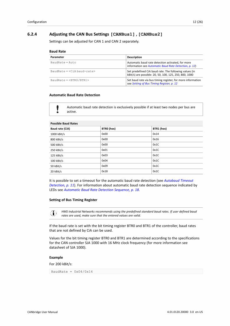
6.2.4 Adjusting the CAN Bus Settings [CANBus1],[CANBus2]Settings can be adjusted for CAN 1 and CAN 2 separately.
Baud RateParameter Description
BaudRate = Auto Automatic baud rate detection activated, for moreinformation see Automatic Baud Rate Detection, p. 12)
BaudRate = <CiA baud-rate> Set predefined CiA baud rate. The following values (inkBit/s) are possible: 20, 50, 100, 125, 250, 800, 1000
BaudRate = <BTR0/BTR1> Set baud rate via bus timing register, for more informationsee Setting of Bus Timing Register, p. 12
Automatic Baud Rate Detection
Automatic baud rate detection is exclusively possible if at least two nodes per bus areactive.
Possible Baud RatesBaud rate (CiA) BTR0 (hex) BTR1 (hex)
1000 kBit/s 0x00 0x14
800 kBit/s 0x00 0x16
500 kBit/s 0x00 0x1C
250 kBit/s 0x01 0x1C
125 kBit/s 0x03 0x1C
100 kBit/s 0x04 0x1C
50 kBit/s 0x09 0x1C
20 kBit/s 0x18 0x1C
It is possible to set a timeout for the automatic baud rate detection (see Autobaud TimeoutDetection, p. 11). For information about automatic baud rate detection sequence indicated byLEDs see Automatic Baud Rate Detection Sequence, p. 18.
Setting of Bus Timing Register
HMS Industrial Networks recommends using the predefined standard baud rates. If user defined baudrates are used, make sure that the entered values are valid.
If the baud rate is set with the bit timing register BTR0 and BTR1 of the controller, baud ratesthat are not defined by CiA can be used.
Values for the bit timing register BTR0 and BTR1 are determined according to the specificationsfor the CAN controller SJA 1000 with 16 MHz clock frequency (for more information seedatasheet of SJA 1000).
Example
For 200 kBit/s:
BaudRate = 0x04/0x14
CANbridge User Manual 4.01.0120.20000 3.0 en-US

Configuration 13 (26)
Frame FormatParameter Description
FrameFormat = std Standard (11 bit identifier)
FrameFormat = ext Extended (29 bit identifier)
Mapping Table
Parameter Description
UseGatewayTable = yes Mapping tables of [CAN1GatewayTable] resp.[CAN2GatewayTable] are used.
UseGatewayTable = no Mapping tables are not used, all messages are transmittedunchanged.
6.2.5 Setting Mapping Tables [CAN1GatewayTable],[CAN2GatewayTable]For each CAN bus a different mapping table is available. The CAN 1 and CAN 2 mapping tablesdefine if a message is forwarded or filtered out. If a message is forwarded the identifier can bechanged. The data of the message remains unchanged.
0x0 = 0x00x100 = 0x200
► Enter the identifier of the message to be received on the left.
► Enter the identifiers to be used when transmitting to the other CAN bus on the right.
Identifiers that are not listed or do not have an entry on the left are not forwarded.
Make sure that repeater mode is off (RepeaterFunctionality = no) and mappingtables are enabled for CAN 1 and CAN 2 (UseGatewayTable = yes).
Data is interpreted differently depending on the setting of the frame format.
If both CAN busses are set to frame format standard:
• 11 bit identifiers left and right
• 2048 entries possible
If frame format standard is translated in extended:
• 11 bit identifiers on the left
• 29 bit identifiers on the right
• 2048 entries possible
If both CAN busses are set to frame format extended:
• 29 bit identifiers left and right
• 128 entries possible
CANbridge User Manual 4.01.0120.20000 3.0 en-US

Configuration 14 (26)
If frame format extended is translated in standard:
• 29 bit identifiers on the left
• 11 bit identifiers on the right
• 128 entries possible
All possible identifiers are listed in the template, mapped 1 to 1:
► If configuration with only 128 possible entries is used, delete surplus entries.
Example
• Standard frames set for CAN 1.
• Extended frames set for CAN 2.
[CAN1GatewayTable]0x0=0x0 ; These messages are forwarded to the0x1=0x1 ; other segment (CAN2) with the0x2=0x2 ; same identifiers…0x100=0x200 ; These messages are forwarded to CAN20x101=0x1005abc ; with the identifiers given0x102=0x202 ; on the right side…0x7fa= ; The identifiers that are not listed0x7fb=no ; or that do not have a0x7fc= ; numerical value on the right side0x7fd= ; are not forwarded to CAN2
CANbridge User Manual 4.01.0120.20000 3.0 en-US

Configuration 15 (26)
6.3 Load Configuration to Device► Connect the serial interface RS232 of the CANbridge and the serial interface of the
computer with a null modem cable.
► Call CANBcfg.exe with parameter —a <filename> —i<name> (e.g. CANBcfg —amyconfig.cfg —iCOM7).
→ Program starts.
► To confirm the question to carry out the download, press key y.
→ Download is started via specified serial interface.
or
► To automate the download add parameter —y when calling CANBcfg.exe (e.g CANbcfg —amyconfig.cfg –iCOM7 —y).
→ Configuration is directly downloaded to the CANbridge.
Fig. 3 Load configuration to device
CANbridge User Manual 4.01.0120.20000 3.0 en-US

Configuration 16 (26)
6.4 Show Current Configuration► To read the current configuration, add parameter —v (e.g CANbcfg —v).
→ File and configuration name are displayed.
Fig. 4 Show configuration
6.5 Standard ConfigurationStandard configuration of CANbridge:
• automatic baud rate detection activated
• repeater mode activated
• both frame formats (standard and extended) are processed simultaneously
[General]TemplateVersion = 01.01.00 ;!Do not change this!RepeaterFunctionality = yesAutoBaudAttemptTimeout = noCANBusOffRecovery = no
[USER]ConfigAlias = “CAN-Bridge AutoBaud Repeater”
[CANBus1]BaudRate = AutoFrameFormat = std ;FrameFormat is ignoredUseGatewayTable = no ;UseGatewayTable is ignored
[CANBus2]BaudRate = AutoFrameFormat = ext ;Frameformat is ignoredUseGatewayTable = no ;UseGatewayTable is ignored
[CAN1GatewayTable] ;Gatewaytable is ignored
[CAN2GatewayTable] ;Gatewaytable is ignored
CANbridge User Manual 4.01.0120.20000 3.0 en-US

Configuration 17 (26)
6.6 Configuration ExampleThe example has the following configuration:
• CAN 1 has standard frame format.
• CAN 1 baud rate is 800 kBit/s.
• CAN 1 and CAN 2 mapping tables are used.
• CAN 2 has extended frame format.
• CAN 2 baud rate is defined by bit timing register.
• bus off recovery is set to 10 seconds.
[General]TemplateVersion = 01.01.00 ;!Do not change this!RepeaterFunctionality = noAutoBaudAttemptTimeout = noCANBusOffRecovery = 10
[USER]ConfigAlias = “CAN-Bridge std/ext/Filter”
[CANBus1]BaudRate = 800FrameFormat = stdUseGatewayTable = yes
[CANBus2]BaudRate = 0x01/0x0cFrameFormat = extUseGatewayTable = yes
[CAN1GatewayTable]0x000 = 0x000 ;normal id retransmission with the0x001 = 0x001 ;same identifier on both sides…0x100 = 0x1234567 ;modify the id and0x101 = 0x1005201 ;translate to Extended Frame…[CAN2GatewayTable]0x004 = 0x004 ;normal id retransmission with the0x006 = 0x006 ;same identifier on both sides…0x1234567 = 0x210 ;modify the id and0x2345678 = 0x211 ;translate to Standard Frame
CANbridge User Manual 4.01.0120.20000 3.0 en-US

Operation 18 (26)
7 Operation
Fig. 5 LED arrays industrial rail version and automotive version
1 Power LED2 CAN 1 LED3 CAN 2 LED4 COM LED
7.1 Automatic Baud Rate Detection SequenceDuring the automatic baud rate detection CAN 1 LED (3), CAN 2 LED (4) and PWR LED (1) indicatethe status.
Status CAN 1 LED CAN 2 LED PWR LEDAutomatic baud rate detectionactive on both channels
Red flashing Red flashing Red flashing
Baud rate detected on CAN 1, baudrate detection on CAN 2 active
Green flashing Red flashing Red flashing
Baud rate on CAN 2 detected oradopted from CAN 1,communication present
Green flashing Green flashing Green
7.2 Power LED (PWR)LED state Description Comments
Green Connected to power supply,microcontroller installed
Device is ready to use.
Red Watchdog reset -
Red flashing (1 Hz) Automatic baud rate detection If no baud rate detected, permanently red.
CANbridge User Manual 4.01.0120.20000 3.0 en-US

Additional Components 19 (26)
7.3 CAN 1/CAN 2 LEDLED state Description Comments
Green Message received or transmittedwithout errors
-
Red flashing Message received or transmitted,error warning level reached
-
Red Bus off No communication possible
7.4 COM LEDLED state Description Comments
Green flashing Message received or transmittedwithout errors
-
Red flashing Message received or transmittedwith errors
-
8 Additional Components8.1 CAN Bus Termination
In the device is no bus termination resistor for the CAN bus integrated. Ixxat offers a bustermination resistor as a feed through connector.
Fig. 6 CAN bus termination resistor
► For ordering information see www.ixxat.com.
CANbridge User Manual 4.01.0120.20000 3.0 en-US

Technical Data 20 (26)
9 Technical DataCAN controller 16 bit microcontroller,, 2xCAN on-chip, CAN 2.0A, 2.0B
CAN transceiver (high-speed) Texas Instruments SN65HVD251
CAN transceiver (low-speed) NXP (Philips) TJA1054
Microcontroller Fujitsu MB90F543, 16 MHz
RAM/Flash 6 kByte/128 kByte
Max. number of CAN bus nodes 120 (high-speed), 32 (low-speed)
CAN bus termination resistor none (high-speed)RTH = RTL = 4.7 kΩ (low-speed)
CAN baud rates 20 kBit to 1 MBit (high-speed)20 kBit to 125 kBit (low-speed)
Dimensions 100 x 85 x 32 mmWeight Approx. 250 g
Operating temperature -20 °C to 70 °C
Storage temperature -40 °C to 85 °C
Power supply Industrial: 9 V to 36 V DCAutomotive: 7 V to 16 V DC
Power consumption Approx. 1.5 W
Relative humidity 10 to 95 %, non-condensing
Housing material Aluminium
Galvanic isolation CAN bus to internal logics1000 V DC/1 sec, 800 V DC/1 min, 700 V AC/1 sec, 500 VAC/1 min
Delay galvanic isolation Typ. 50 ns
CAN pass through delay Approx. 70 μs with standard frame formatApprox. 150 μs with extended frame format
CAN message buffer 100 messages per CAN bus
Protection class IP 40
CANbridge User Manual 4.01.0120.20000 3.0 en-US

Support/Return Hardware 21 (26)
10 Support/Return Hardware10.1 Support
► To contact support, go to www.ixxat.com/technical-support/contact-technical-support.
► Scroll down and click button mysupport.hms.se to register a support case.
10.2 Return Hardware► On www.ixxat.com/support/product-returns click button Portal to access the support portal.
► In the support portal select Submit Product Return (RMA).
► Read the information and click Create RMA Case.
► Register a support account and sign in.
► Fill in the form for warranty claims and repair.
► Print out the Product Return Number (PRN resp. RMA).
► Pack product in a physically- and ESD-safe way, use original packaging if possible.
► Enclose PRN number.
► Observe further notes on www.ixxat.com.
► Return hardware.
11 Disposal► Dispose of product according to national laws and regulations.
► Observe further notes about disposal of products on www.ixxat.com.
CANbridge User Manual 4.01.0120.20000 3.0 en-US

This page intentionally left blank

Appendix A: Regulatory Compliance 23 (26)
A Regulatory ComplianceA.1 EMC Compliance (CE)
The product is in compliance with the Electromagnetic Compatibility Directive. More informationand the Declaration of Conformity is found at www.ixxat.com.
A.2 FCC Compliance StatementThis device complies with Part 15 of the FCC Rules. Operation is subject to the following twoconditions:
• This device may not cause harmful interference.
• This device must accept any interference received, including interference that may causeundesired operation.
Product name CANbridge
Responsible party HMS Industrial Networks Inc
Address 35 E. Wacker Dr, Suite 1700Chicago , IL 60601
Phone +1 312 829 0601
Any changes or modifications not expressly approved by HMS Industrial Networks couldvoid the user's authority to operate the equipment.
This equipment has been tested and found to comply with the limits for a Class A digitaldevice, pursuant to part 15 of the FCC Rules. These limits are designed to providereasonable protection against harmful interference when the equipment is operated in acommercial environment. This equipment generates, uses, and can radiate radiofrequency energy and, if not installed and used in accordance with the instructionmanual, may cause harmful interference to radio communications. Operation of thisequipment in a residential area is likely to cause harmful interference in which case theuser will be required to correct the interference at his own expense.
CANbridge User Manual 4.01.0120.20000 3.0 en-US
Appendix A: Regulatory Compliance 24 (26)
A.3 Disposal and recycling
You must dispose of this product properly according to local laws and regulations. Because thisproduct contains electronic components, it must be disposed of separately from householdwaste. When this product reaches its end of life, contact local authorities to learn about disposaland recycling options, or simply drop it off at your local HMS office or return it to HMS.
For more information, see www.hms-networks.com.
CANbridge User Manual 4.01.0120.20000 3.0 en-US

This page intentionally left blank

last page
© 2021 HMS Industrial NetworksBox 4126300 04 Halmstad, Sweden
[email protected] 4.01.0120.20000 3.0 en-US / 2021-10-20 / 23599