Embed Size (px)
DESCRIPTION
CANape tuning software press release.
Citation preview
1
Technical Article
April 2011
Riding on the Razor’s Edge
Anyone who has been to a weekend race event and seen mid-class
vehicles – with production engines with hundreds of horsepower –
covering a distance of a quarter mile (402.34 m) with deafening
noise and incredible accelerations, is very likely watching a drag
race (Figure 1). Because top engine performance is required very
quickly in such acceleration races, a large share of development
effort goes into calibrating the engine controller. The art of the
race team’s efforts is to achieve optimal results with a minimal
budget. It is necessary to approach the stress limits of the engine
so closely that it delivers maximum power without being destroyed.
Not only the driving but also the process of calibrating the engine
can best be described as “a ride on the razor’s edge.”
Optimally calibrated engine controller enables maximum power
In a personal endeavor, it takes a great deal of passion and enthu-
siasm to spend the time and money it takes to build and maintain a
vehicle for drag racing. The key item here is the engine. A
production engine is purchased, which is then modified by
mechanical rebuilding to prepare it for the demands of racing.
While the rebuild represents one side of the coin, the other
involves calibrating the engine controller. All sorts of challenges
must be mastered here, since the parameters of the production
engine controller hardly harmonize with the modified engine any
longer.
Measuring and calibrating ECUs is a challenging but daily rou-
tine in the work of carmakers and suppliers involved in production
development. While calibrators run various course scenarios with
the engine on the test stand and in the vehicle, they access inter-
nal parameters and ECU measurement variables via an A2L descrip-
tion file and find the optimal parameters. The complexity of this
task significantly increases due to a whole series of constraints. On
the one hand, numerous engine and vehicle variants need to be
considered, and different emissions standards need to be met. At
the same time, the ECU must be imprinted with an OEM-specific
driving behavior. All optimizations are also subject to the premise
that certain fuel economy limits must be observed. Engine
Optimal parameterization of an engine controller for drag racing
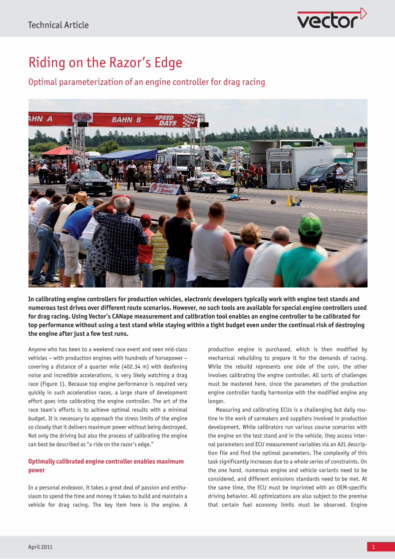
In calibrating engine controllers for production vehicles, electronic developers typically work with engine test stands and numerous test drives over different route scenarios. However, no such tools are available for special engine controllers used for drag racing. Using Vector’s CANape measurement and calibration tool enables an engine controller to be calibrated for top performance without using a test stand while staying within a tight budget even under the continual risk of destroying the engine after just a few test runs.
2
Technical Article
April 2011
calibrating is simplified by the fact that calibrators and software
developers control the entire software process together. This rang-
es from creating the code and developing the software to the com-
piler/linker run, A2L generation and the flash process.
Optimal results in just a few test drives
The engine calibrating process for drag racing is fundamentally dif-
ferent. Neither maintaining fuel economy nor supporting different
engine or vehicle variants play a role here; rather, all efforts are
directed toward one goal: covering the approx. 400 meter distance
as quickly as possible. Furthermore, the racing teams are not cor-
porations with strong financial backing; rather, they are typically
private individuals pursuing an expensive hobby. If faulty calibra-
tion leads to engine destruction, a lot of money needs to be spent
to buy a new one.
No test stands are available for engine test runs either. For one,
there are no suitable test stands due to the lack of demand for this
niche application. Secondly, it is not possible to optimize the
engines at their maximum speeds of up to 10,000 rpm and up to 3.5
bar charge pressure in quasi-static operation. The loads are so great
that the engines could only withstand these speeds for a brief period
of time (2 to 3 seconds per gear) without succumbing to heat
overload.
The only feasible approach for the race teams is to acquire as
many measurement variables as possible during the drive and then
optimize calibration parameters based on this information. Howev-
er, this approach too necessitates living with all sorts of limita-
tions. On the one hand, the engines can only be used for a few
drives before they need to be replaced. On the other, the drives
usually last less than ten seconds. Therefore, the key to success or
failure of the optimization process lies in finding an extraordinari-
ly rational method.
Special engine controller replaces production device
A highly efficient engine controller for drag racing comes from the
maf-map-engineering company of Berlin, Germany. This company,
founded on a passion for car racing, offers a complete solution that
gets maximum power out of the engines. Its capabilities are illus-
trated by the fastest VW Polo in the world, which trumps with 1,047
horsepower. Its performance is based on the ECU481 engine con-
troller, whose entire hardware and software was developed by the
company independently for ideal control of all components. The
software is created based on physical models, whereby the Scilab
modeling environment is used with an associated code generator
for the functional layer. The basic software is still manually coded
in C.
Since no test stand operation and only a few short test drives
are possible, a primary focus is on reliable acquisition of all rele-
vant parameters from the ECU via a cost-effective interface. That is
why the standardized measurement and calibration protocol XCP
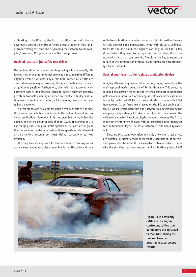
Figure 1: To optimally calibrate the engine controller, calibration parameters are adjusted in real-time during the test run based on acquired measurement results.
3
Technical Article
April 2011
on Ethernet was chosen. Early on, a decision was made to search
for a satisfactory professional tool which lead the team to the CAN-
ape measurement and calibration tool from Vector.
Automated parameter optimization in real-time
Key ECU parameters are calibrated by the maf-map-engineering
specialists or the individual racing team; they are not calibrated
after the test run, but during the test run itself – in real-time –
based on acquired measurement results. Because of the extremely
short test driving times it is impossible for the driver to mentally
note all of the data, derive meaningful decisions from it and still
send the right values to the ECU. CANape functions that enable
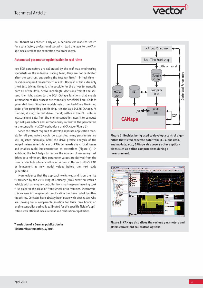
automation of this process are especially beneficial here. Code is
generated from Simulink models using the Real-Time Workshop
code; after compiling and linking, it is run as a DLL in CANape. At
runtime, during the test drive, the algorithm in the DLL obtains
measurement data from the engine controller, uses it to compute
optimal parameters and autonomously calibrates the parameters
in the controller via XCP mechanisms and CANape (Figure 2).
Since the effort required to develop separate application mod-
els for all parameters would be excessive, many parameters are
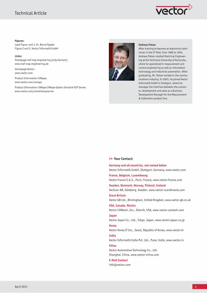
still adjusted manually. After the drive precise analysis of the
logged measurement data with CANape reveals any critical issues
and enables rapid implementation of corrections (Figure 3). In
addition, the tool helps to reduce the number of necessary test
drives to a minimum. New parameter values are derived from the
results, which developers either set online in the controller’s RAM
or implement as new model values before the next code
generation.
More evidence that the approach works well and is on the rise
is provided by the 2010 King of Germany (KOG) event, in which a
vehicle with an engine controller from maf-map-engineering took
first place in the class of front-wheel drive vehicles. Meanwhile,
this success in the general classification has been noted by other
industries. Contacts have already been made with boat racers who
are looking for a comparable solution for their race boats: an
engine controller optimally calibrated for this specific field of appli-
cation with efficient measurement and calibration capabilities.
Translation of a German publication in Elektronik automotive, 4/2011
Fig ure 2: Besides being used to develop a control algo-rithm that is fed concrete data from ECUs, bus data, analog data, etc., CANape also covers other applica-tions such as online computations during a measurement.
Fig ure 3: CANape visualizes the various parameters and offers convenient calibration options
4
Technical Article
April 2011
Figures:Lead Figure and 1: Dr. Bernd SeydelFigure 2 and 3: Vector Informatik GmbH
Links:Homepage maf map engineering [only German]: www.maf-map-engineering.de
Homepage Vector: www.vector.com
Product Information CANape: www.vector.com/canape
Product Information CANape CANape Option Simulink XCP Server: www.vector.com/simulinkxcpserver
>> Your Contact:
Germany and all countries, not named belowVector Informatik GmbH, Stuttgart, Germany, www.vector.com
France, Belgium, Luxembourg Vector France S.A.S., Paris, France, www.vector-france.com
Sweden, Denmark, Norway, Finland, IcelandVecScan AB, Göteborg, Sweden, www.vector-scandinavia.com
Great BritainVector GB Ltd., Birmingham, United Kingdom, www.vector-gb.co.uk
USA, Canada, MexicoVector CANtech, Inc., Detroit, USA, www.vector-cantech.com
JapanVector Japan Co., Ltd., Tokyo, Japan, www.vector-japan.co.jp
KoreaVector Korea IT Inc., Seoul, Republic of Korea, www.vector.kr
IndiaVector Informatik India Pvt. Ltd., Pune, India, www.vector.in
ChinaVector Automotive Technology Co., Ltd.
Shanghai, China, www.vector-china.com
E-Mail [email protected]
Andreas Patzer After training to become an electronics tech-nician in the IT field, from 1986 to 1993, Andreas Patzer studied Electrical Engineer-ing at the Technical University of Karlsruhe, where he specialized in measurement and control engineering as well as information technology and industrial automation. After graduating, Mr. Patzer worked in the commu-nications industry. In 2003, he joined Vector Informatik GmbH in Stuttgart, where he manages the interface between the custom-er, development and sales as a Business Development Manager for the Measurement & Calibration product line.